fluid_mechanics
546 Chapter 10 ■ Open-Channel Flow so that the kinetic energy term in Eq. 10.12 becomes V dV 2 g dx V dy dy Fr2 gy dx dx (10.13) dy dx S f = S o S f > S o 0 Fr 0.5 1.5 2 where Fr V1gy2 1 2 is the local Froude number of the flow. Substituting Eq. 10.13 into Eq. 10.12 and simplifying gives dy dx 1S f S 0 2 11 Fr 2 2 (10.14) It is seen that the rate of change of fluid depth, dydx, depends on the local slope of the channel bottom, S 0 , the slope of the energy line, S f , and the Froude number, Fr. As shown by the figure in the margin, the value of dydx can be either negative, zero, or positive, depending on the values of these three parameters. That is, the channel flow depth may be constant or it may increase or decrease in the flow direction, depending on the values of S 0 , S f , and Fr. The behavior of subcritical flow may be the opposite of that for supercritical flow, as seen by the denominator, 1 Fr 2 , of Eq. 10.14. Although in the derivation of Eq. 10.14 we assumed q is constant 1i.e., a rectangular channel2, Eq. 10.14 is valid for channels of any constant cross-sectional shape, provided the Froude number is interpreted properly 1Ref. 32. In this book we will consider only rectangular cross-sectional channels when using this equation. S f < S o F I G U R E 10.8 10.4 Uniform Depth Channel Flow V10.6 Merging channels The wall shear stress acts on the wetted perimeter of the channel. Many channels are designed to carry fluid at a uniform depth all along their length. Irrigation canals are frequently of uniform depth and cross section for considerable lengths. Natural channels such as rivers and creeks are seldom of uniform shape, although a reasonable approximation to the flowrate in such channels can often be obtained by assuming uniform flow. In this section we will discuss various aspects of such flows. Uniform depth flow 1dydx 02 can be accomplished by adjusting the bottom slope, S 0 , so that it precisely equals the slope of the energy line, S f . That is, S 0 S f . This can be seen from Eq. 10.14. From an energy point of view, uniform depth flow is achieved by a balance between the potential energy lost by the fluid as it coasts downhill and the energy that is dissipated by viscous effects 1head loss2 associated with shear stresses throughout the fluid. Similar conclusions can be reached from a force balance analysis as discussed in the following section. 10.4.1 Uniform Flow Approximations We consider fluid flowing in an open channel of constant cross-sectional size and shape such that the depth of flow remains constant as is indicated in Fig. 10.8. The area of the section is A and the wetted perimeter 1i.e., the length of the perimeter of the cross section in contact with the fluid2 is P. The interaction between the fluid and the atmosphere at the free surface is assumed negligible so that this portion of the perimeter is not included in the definition of the wetted perimeter. Since the fluid must adhere to the solid surfaces, the actual velocity distribution in an open channel is not uniform. Some typical velocity profiles measured in channels of various shapes are indicated in Fig. 10.9a. The maximum velocity is often found somewhat below the free surface, a Free surface A = flow area Q a (a) P = wetted perimeter Section a – a (b) Uniform flow in an open channel.
10.4 Uniform Depth Channel Flow 547 Lines of constant velocity y Centerline velocity profiles y u u (a) Actual Uniform τ w (b) τ w = shear stress distribution F I G U R E 10.9 Typical velocity and shear stress distributions in an open channel: (a) velocity distribution throughout the cross section, (b) shear stress distribution on the wetted perimeter. and the fluid velocity is zero on the wetted perimeter, where a wall shear stress, t w , is developed. This shear stress is seldom uniform along the wetted perimeter, with typical variations as are indicated in Fig. 10.9b. Fortunately, reasonable analytical results can be obtained by assuming a uniform velocity profile, V, and a constant wall shear stress, t w . Similar assumptions were made for pipe flow situations 1Chapter 82, with the friction factor being used to obtain the head loss. F l u i d s i n t h e N e w s Plumbing the Everglades Because of all of the economic development that has occurred in southern Florida, the natural drainage pattern of that area has been greatly altered during the past century. Previously there was a vast network of surface flow southward from the Orlando area, to Lake Okeechobee, through the Everglades, and out to the Gulf of Mexico. Currently a vast amount of freshwater from Lake Okeechobee and surrounding waterways (1.7 billion gallons per day) is sluiced into the ocean for flood control, bypassing the Everglades. A new long-term Comprehensive Everglades Restoration Plan is being implemented to restore, preserve, and protect the south Florida ecosystem. Included in the plan are the use of numerous aquifer-storage-and-recovery systems that will recharge the ecosystem. In addition, surface water reservoirs using artificial wetlands will clean agricultural runoff. In an attempt to improve the historical flow from north to south, old levees will be removed, parts of the Tamiami Trail causeway will be altered, and stored water will be redirected through miles of new pipes and rebuilt canals. Strictly speaking, the Everglades will not be “restored.” However, by 2030, 1.6 million acres of national parkland will have cleaner water and more of it. (See Problem 10.77.) 10.4.2 The Chezy and Manning Equations The basic equations used to determine the uniform flowrate in open channels were derived many years ago. Continual refinements have taken place to obtain better values of the empirical coefficients involved. The result is a semiempirical equation that provides reasonable engineering results. A more refined analysis is perhaps not warranted because of the complexity and uncertainty of the flow geometry 1i.e., channel shape and the irregular makeup of the wetted perimeter, particularly for natural channels2. Under the assumptions of steady uniform flow, the x component of the momentum equation 1Eq. 5.222 applied to the control volume indicated in Fig. 10.10 simply reduces to F x rQ1V 2 V 1 2 0 For steady, uniform depth flow in an open channel there is no fluid acceleration. since V 1 V 2 . There is no acceleration of the fluid, and the momentum flux across section 112 is the same as that across section 122. The flow is governed by a simple balance between the forces in the direction of the flow. Thus, F x 0, or F 1 F 2 t w P/ w sin u 0 (10.15)
- Page 520 and 521: 496 Chapter 9 ■ Flow over Immerse
- Page 522 and 523: 498 Chapter 9 ■ Flow over Immerse
- Page 524 and 525: 500 Chapter 9 ■ Flow over Immerse
- Page 526 and 527: 502 Chapter 9 ■ Flow over Immerse
- Page 528 and 529: 504 Chapter 9 ■ Flow over Immerse
- Page 530 and 531: 506 Chapter 9 ■ Flow over Immerse
- Page 532 and 533: 508 Chapter 9 ■ Flow over Immerse
- Page 534 and 535: 510 Chapter 9 ■ Flow over Immerse
- Page 536 and 537: 512 Chapter 9 ■ Flow over Immerse
- Page 538 and 539: 514 Chapter 9 ■ Flow over Immerse
- Page 540 and 541: 516 Chapter 9 ■ Flow over Immerse
- Page 542 and 543: 518 Chapter 9 ■ Flow over Immerse
- Page 544 and 545: 520 Chapter 9 ■ Flow over Immerse
- Page 546 and 547: 522 Chapter 9 ■ Flow over Immerse
- Page 548 and 549: 524 Chapter 9 ■ Flow over Immerse
- Page 550 and 551: 526 Chapter 9 ■ Flow over Immerse
- Page 552 and 553: 528 Chapter 9 ■ Flow over Immerse
- Page 554 and 555: ∋ 530 Chapter 9 ■ Flow over Imm
- Page 556 and 557: 532 Chapter 9 ■ Flow over Immerse
- Page 558 and 559: 10 Open-Channel Flow CHAPTER OPENIN
- Page 560 and 561: 536 Chapter 10 ■ Open-Channel Flo
- Page 562 and 563: 538 Chapter 10 ■ Open-Channel Flo
- Page 564 and 565: 540 Chapter 10 ■ Open-Channel Flo
- Page 566 and 567: 542 Chapter 10 ■ Open-Channel Flo
- Page 568 and 569: 544 Chapter 10 ■ Open-Channel Flo
- Page 572 and 573: 548 Chapter 10 ■ Open-Channel Flo
- Page 574 and 575: 550 Chapter 10 ■ Open-Channel Flo
- Page 576 and 577: 552 Chapter 10 ■ Open-Channel Flo
- Page 578 and 579: 554 Chapter 10 ■ Open-Channel Flo
- Page 580 and 581: 556 Chapter 10 ■ Open-Channel Flo
- Page 582 and 583: 558 Chapter 10 ■ Open-Channel Flo
- Page 584 and 585: 560 Chapter 10 ■ Open-Channel Flo
- Page 586 and 587: 562 Chapter 10 ■ Open-Channel Flo
- Page 588 and 589: 564 Chapter 10 ■ Open-Channel Flo
- Page 590 and 591: 566 Chapter 10 ■ Open-Channel Flo
- Page 592 and 593: 568 Chapter 10 ■ Open-Channel Flo
- Page 594 and 595: 570 Chapter 10 ■ Open-Channel Flo
- Page 596 and 597: 572 Chapter 10 ■ Open-Channel Flo
- Page 598 and 599: 574 Chapter 10 ■ Open-Channel Flo
- Page 600 and 601: 576 Chapter 10 ■ Open-Channel Flo
- Page 602 and 603: 578 Chapter 10 ■ Open-Channel Flo
- Page 604 and 605: 580 Chapter 11 ■ Compressible Flo
- Page 606 and 607: 582 Chapter 11 ■ Compressible Flo
- Page 608 and 609: 584 Chapter 11 ■ Compressible Flo
- Page 610 and 611: 586 Chapter 11 ■ Compressible Flo
- Page 612 and 613: 588 Chapter 11 ■ Compressible Flo
- Page 614 and 615: 590 Chapter 11 ■ Compressible Flo
- Page 616 and 617: 592 Chapter 11 ■ Compressible Flo
- Page 618 and 619: 594 Chapter 11 ■ Compressible Flo
546 Chapter 10 ■ Open-Channel Flow<br />
so that the kinetic energy term in Eq. 10.12 becomes<br />
V dV<br />
2<br />
g dx V dy dy<br />
Fr2<br />
gy dx dx<br />
(10.13)<br />
dy<br />
dx S f = S o<br />
S f > S o<br />
0<br />
Fr<br />
0.5 1.5 2<br />
where Fr V1gy2 1 2<br />
is the local Froude number of the flow. Substituting Eq. 10.13 into Eq. 10.12<br />
and simplifying gives<br />
dy<br />
dx 1S f S 0 2<br />
11 Fr 2 2<br />
(10.14)<br />
It is seen that the rate of change of <strong>fluid</strong> depth, dydx, depends on the local slope of the<br />
channel bottom, S 0 , the slope of the energy line, S f , and the Froude number, Fr. As shown by the<br />
figure in the margin, the value of dydx can be either negative, zero, or positive, depending on<br />
the values of these three parameters. That is, the channel flow depth may be constant or it may<br />
increase or decrease in the flow direction, depending on the values of S 0 , S f , and Fr. The behavior<br />
of subcritical flow may be the opposite of that for supercritical flow, as seen by the denominator,<br />
1 Fr 2 , of Eq. 10.14.<br />
Although in the derivation of Eq. 10.14 we assumed q is constant 1i.e., a rectangular channel2,<br />
Eq. 10.14 is valid for channels of any constant cross-sectional shape, provided the Froude number<br />
is interpreted properly 1Ref. 32. In this book we will consider only rectangular cross-sectional<br />
channels when using this equation.<br />
S f < S o<br />
F I G U R E 10.8<br />
10.4 Uniform Depth Channel Flow<br />
V10.6 Merging<br />
channels<br />
The wall shear<br />
stress acts on the<br />
wetted perimeter<br />
of the channel.<br />
Many channels are designed to carry <strong>fluid</strong> at a uniform depth all along their length. Irrigation canals<br />
are frequently of uniform depth and cross section for considerable lengths. Natural channels such<br />
as rivers and creeks are seldom of uniform shape, although a reasonable approximation to the<br />
flowrate in such channels can often be obtained by assuming uniform flow. In this section we will<br />
discuss various aspects of such flows.<br />
Uniform depth flow 1dydx 02 can be accomplished by adjusting the bottom slope, S 0 , so<br />
that it precisely equals the slope of the energy line, S f . That is, S 0 S f . This can be seen from Eq.<br />
10.14. From an energy point of view, uniform depth flow is achieved by a balance between the<br />
potential energy lost by the <strong>fluid</strong> as it coasts downhill and the energy that is dissipated by viscous<br />
effects 1head loss2 associated with shear stresses throughout the <strong>fluid</strong>. Similar conclusions can be<br />
reached from a force balance analysis as discussed in the following section.<br />
10.4.1 Uniform Flow Approximations<br />
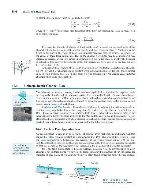
We consider <strong>fluid</strong> flowing in an open channel of constant cross-sectional size and shape such that<br />
the depth of flow remains constant as is indicated in Fig. 10.8. The area of the section is A and<br />
the wetted perimeter 1i.e., the length of the perimeter of the cross section in contact with the <strong>fluid</strong>2<br />
is P. The interaction between the <strong>fluid</strong> and the atmosphere at the free surface is assumed negligible<br />
so that this portion of the perimeter is not included in the definition of the wetted perimeter.<br />
Since the <strong>fluid</strong> must adhere to the solid surfaces, the actual velocity distribution in an open<br />
channel is not uniform. Some typical velocity profiles measured in channels of various shapes are<br />
indicated in Fig. 10.9a. The maximum velocity is often found somewhat below the free surface,<br />
a<br />
Free surface<br />
A = flow area<br />
Q<br />
a<br />
(a)<br />
P = wetted<br />
perimeter<br />
Section a – a<br />
(b)<br />
Uniform flow in an open channel.


