fluid_mechanics
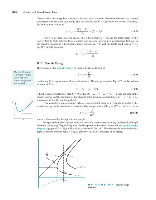
542 Chapter 10 ■ Open-Channel Flow Chapter 3 that the energy line is located a distance z 1the elevation from some datum to the channel bottom2 plus the pressure head 1 pg2 plus the velocity head 1V 2 2g2 above the datum. Therefore, Eq. 10.6 can be written as y 1 y 2 1V 2 2 V 2 12 1S 2g f S 0 2/ (10.7) If there is no head loss, the energy line is horizontal 1S f 02, and the total energy of the flow is free to shift between kinetic energy and potential energy in a conservative fashion. In the specific instance of a horizontal channel bottom 1S 0 02 and negligible head loss 1S f 02, Eq. 10.7 simply becomes y 1 y 2 1V 2 2 V 2 12 2g E The specific energy is the sum of potential energy and kinetic energy (per unit weight). q = constant y 10.3.1 Specific Energy The concept of the specific energy or specific head, E, defined as E y V 2 2g (10.8) is often useful in open-channel flow considerations. The energy equation, Eq. 10.7, can be written in terms of E as E 1 E 2 1S f S 0 2/ (10.9) If head losses are negligible, then S f 0 so that 1S f S 0 2/ S 0 / z 2 z 1 and the sum of the specific energy and the elevation of the channel bottom remains constant 1i.e., E 1 z 1 E 2 z 2 , a statement of the Bernoulli equation2. If we consider a simple channel whose cross-sectional shape is a rectangle of width b, the specific energy can be written in terms of the flowrate per unit width, q Qb Vybb Vy, as E y 2gy 2 (10.10) which is illustrated by the figure in the margin. For a given channel of constant width, the value of q remains constant along the channel, although the depth, y, may vary. To gain insight into the flow processes involved, we consider the specific energy diagram, a graph of E E1y2, with q fixed, as shown in Fig. 10.7. The relationship between the flow depth, y, and the velocity head, V 2 2g, as given by Eq. 10.8 is indicated in the figure. q2 y V 2 2g y = E y sub y q = q" > q' y c E min E y sup q = q' y neg F I G U R E 10.7 diagram. Specific energy
10.3 Energy Considerations 543 For a given value of specific energy, a flow may have alternate depths. For given q and E, Eq. 10.10 is a cubic equation 3y 3 Ey 2 1q 2 2g2 04 with three solutions, y sup , y sub , and y neg . If the specific energy is large enough 1i.e., E 7 E min , where E min is a function of q2, two of the solutions are positive and the other, y neg , is negative. The negative root, represented by the curved dashed line in Fig. 10.7, has no physical meaning and can be ignored. Thus, for a given flowrate and specific energy there are two possible depths, unless the vertical line from the E axis does not intersect the specific energy curve corresponding to the value of q given 1i.e., E 6 E min 2. These two depths are termed alternate depths. For large values of E the upper and lower branches of the specific energy diagram 1y sub and y sup 2 approach y E and y 0, respectively. These limits correspond to a very deep channel flowing very slowly 1E y V 2 2g S y as y S with q Vy fixed2, or a very high-speed flow in a shallow channel 1E y V 2 2g S V 2 2g as y S 02. As is indicated in Fig. 10.7, y sup 6 y sub . Thus, since q Vy is constant along the curve, it follows that V sup 7 V sub , where the subscripts “sub” and “sup” on the velocities correspond to the depths so labeled. The specific energy diagram consists of two portions divided by the E min “nose” of the curve. We will show that the flow conditions at this location correspond to critical conditions 1Fr 12, those on the upper portion of the curve correspond to subcritical conditions 1hence, the “sub” subscript2, and those on the lower portion of the curve correspond to supercritical conditions 1hence, the “sup” subscript2. To determine the value of E min , we use Eq. 10.10 and set dEdy 0 to obtain dE dy 1 q2 gy 0 3 or y c a q2 g b 13 (10.11) where the subscript “c” denotes conditions at E min . By substituting this back into Eq. 10.10 we obtain E min 3y c 2 By combining Eq. 10.11 and V c qy c , we obtain V c q 1y3 2 c g 12 2 1gy y c y c c y Fr < 1 Fr > 1 E Fr = 1 or Fr c V c1gy c 2 12 1. Thus, critical conditions 1Fr 12 occur at the location of E min . Since the layer is deeper and the velocity smaller for the upper part of the specific energy diagram 1compared with the conditions at E min 2, such flows are subcritical 1Fr 6 12. Conversely, flows for the lower part of the diagram are supercritical. This is shown by the figure in the margin. Thus, for a given flowrate, q, if E 7 E min there are two possible depths of flow, one subcritical and the other supercritical. It is often possible to determine various characteristics of a flow by considering the specific energy diagram. Example 10.2 illustrates this for a situation in which the channel bottom elevation is not constant. E XAMPLE 10.2 Specific Energy Diagram—Quantitative GIVEN Water flows up a 0.5-ft-tall ramp in a constant width rectangular channel at a rate q 5.75 ft 2 s as is shown in Fig. E10.2a. 1For now disregard the “bump.”2 The upstream depth is 2.3 ft and viscous effects are negligible. FIND Determine the elevation of the water surface downstream of the ramp, y 2 z 2 .
- Page 516 and 517: 492 Chapter 9 ■ Flow over Immerse
- Page 518 and 519: 494 Chapter 9 ■ Flow over Immerse
- Page 520 and 521: 496 Chapter 9 ■ Flow over Immerse
- Page 522 and 523: 498 Chapter 9 ■ Flow over Immerse
- Page 524 and 525: 500 Chapter 9 ■ Flow over Immerse
- Page 526 and 527: 502 Chapter 9 ■ Flow over Immerse
- Page 528 and 529: 504 Chapter 9 ■ Flow over Immerse
- Page 530 and 531: 506 Chapter 9 ■ Flow over Immerse
- Page 532 and 533: 508 Chapter 9 ■ Flow over Immerse
- Page 534 and 535: 510 Chapter 9 ■ Flow over Immerse
- Page 536 and 537: 512 Chapter 9 ■ Flow over Immerse
- Page 538 and 539: 514 Chapter 9 ■ Flow over Immerse
- Page 540 and 541: 516 Chapter 9 ■ Flow over Immerse
- Page 542 and 543: 518 Chapter 9 ■ Flow over Immerse
- Page 544 and 545: 520 Chapter 9 ■ Flow over Immerse
- Page 546 and 547: 522 Chapter 9 ■ Flow over Immerse
- Page 548 and 549: 524 Chapter 9 ■ Flow over Immerse
- Page 550 and 551: 526 Chapter 9 ■ Flow over Immerse
- Page 552 and 553: 528 Chapter 9 ■ Flow over Immerse
- Page 554 and 555: ∋ 530 Chapter 9 ■ Flow over Imm
- Page 556 and 557: 532 Chapter 9 ■ Flow over Immerse
- Page 558 and 559: 10 Open-Channel Flow CHAPTER OPENIN
- Page 560 and 561: 536 Chapter 10 ■ Open-Channel Flo
- Page 562 and 563: 538 Chapter 10 ■ Open-Channel Flo
- Page 564 and 565: 540 Chapter 10 ■ Open-Channel Flo
- Page 568 and 569: 544 Chapter 10 ■ Open-Channel Flo
- Page 570 and 571: 546 Chapter 10 ■ Open-Channel Flo
- Page 572 and 573: 548 Chapter 10 ■ Open-Channel Flo
- Page 574 and 575: 550 Chapter 10 ■ Open-Channel Flo
- Page 576 and 577: 552 Chapter 10 ■ Open-Channel Flo
- Page 578 and 579: 554 Chapter 10 ■ Open-Channel Flo
- Page 580 and 581: 556 Chapter 10 ■ Open-Channel Flo
- Page 582 and 583: 558 Chapter 10 ■ Open-Channel Flo
- Page 584 and 585: 560 Chapter 10 ■ Open-Channel Flo
- Page 586 and 587: 562 Chapter 10 ■ Open-Channel Flo
- Page 588 and 589: 564 Chapter 10 ■ Open-Channel Flo
- Page 590 and 591: 566 Chapter 10 ■ Open-Channel Flo
- Page 592 and 593: 568 Chapter 10 ■ Open-Channel Flo
- Page 594 and 595: 570 Chapter 10 ■ Open-Channel Flo
- Page 596 and 597: 572 Chapter 10 ■ Open-Channel Flo
- Page 598 and 599: 574 Chapter 10 ■ Open-Channel Flo
- Page 600 and 601: 576 Chapter 10 ■ Open-Channel Flo
- Page 602 and 603: 578 Chapter 10 ■ Open-Channel Flo
- Page 604 and 605: 580 Chapter 11 ■ Compressible Flo
- Page 606 and 607: 582 Chapter 11 ■ Compressible Flo
- Page 608 and 609: 584 Chapter 11 ■ Compressible Flo
- Page 610 and 611: 586 Chapter 11 ■ Compressible Flo
- Page 612 and 613: 588 Chapter 11 ■ Compressible Flo
- Page 614 and 615: 590 Chapter 11 ■ Compressible Flo
542 Chapter 10 ■ Open-Channel Flow<br />
Chapter 3 that the energy line is located a distance z 1the elevation from some datum to the channel<br />
bottom2 plus the pressure head 1 pg2 plus the velocity head 1V 2 2g2 above the datum. Therefore,<br />
Eq. 10.6 can be written as<br />
y 1 y 2 1V 2<br />
2 V 2 12<br />
1S<br />
2g<br />
f S 0 2/<br />
(10.7)<br />
If there is no head loss, the energy line is horizontal 1S f 02, and the total energy of the<br />
flow is free to shift between kinetic energy and potential energy in a conservative fashion. In<br />
the specific instance of a horizontal channel bottom 1S 0 02 and negligible head loss 1S f 02,<br />
Eq. 10.7 simply becomes<br />
y 1 y 2 1V 2 2 V 2 12<br />
2g<br />
E<br />
The specific energy<br />
is the sum of potential<br />
energy and<br />
kinetic energy (per<br />
unit weight).<br />
q = constant<br />
y<br />
10.3.1 Specific Energy<br />
The concept of the specific energy or specific head, E, defined as<br />
E y V 2<br />
2g<br />
(10.8)<br />
is often useful in open-channel flow considerations. The energy equation, Eq. 10.7, can be written<br />
in terms of E as<br />
E 1 E 2 1S f S 0 2/<br />
(10.9)<br />
If head losses are negligible, then S f 0 so that 1S f S 0 2/ S 0 / z 2 z 1 and the sum of the<br />
specific energy and the elevation of the channel bottom remains constant 1i.e., E 1 z 1 E 2 z 2 ,<br />
a statement of the Bernoulli equation2.<br />
If we consider a simple channel whose cross-sectional shape is a rectangle of width b, the<br />
specific energy can be written in terms of the flowrate per unit width, q Qb Vybb Vy, as<br />
E y <br />
2gy 2<br />
(10.10)<br />
which is illustrated by the figure in the margin.<br />
For a given channel of constant width, the value of q remains constant along the channel, although<br />
the depth, y, may vary. To gain insight into the flow processes involved, we consider the specific energy<br />
diagram, a graph of E E1y2, with q fixed, as shown in Fig. 10.7. The relationship between the flow<br />
depth, y, and the velocity head, V 2 2g, as given by Eq. 10.8 is indicated in the figure.<br />
q2<br />
y<br />
V 2<br />
2g<br />
y = E<br />
y sub<br />
y<br />
q = q" > q'<br />
y c<br />
E min E<br />
y sup<br />
q = q'<br />
y neg<br />
F I G U R E 10.7<br />
diagram.<br />
Specific energy


