fluid_mechanics
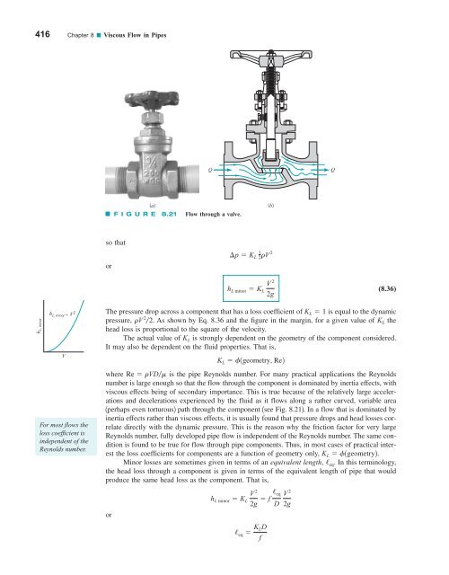
416 Chapter 8 ■ Viscous Flow in Pipes Q Q (a) F I G U R E 8.21 Flow through a valve. (b) so that or ¢p K L 1 2rV 2 h L minor K L V 2 2g (8.36) h L, minor ~ V 2 h L, minor V For most flows the loss coefficient is independent of the Reynolds number. The pressure drop across a component that has a loss coefficient of K L 1 is equal to the dynamic pressure, rV 2 2. As shown by Eq. 8.36 and the figure in the margin, for a given value of K L the head loss is proportional to the square of the velocity. The actual value of K L is strongly dependent on the geometry of the component considered. It may also be dependent on the fluid properties. That is, where Re rVDm is the pipe Reynolds number. For many practical applications the Reynolds number is large enough so that the flow through the component is dominated by inertia effects, with viscous effects being of secondary importance. This is true because of the relatively large accelerations and decelerations experienced by the fluid as it flows along a rather curved, variable area 1perhaps even torturous2 path through the component 1see Fig. 8.212. In a flow that is dominated by inertia effects rather than viscous effects, it is usually found that pressure drops and head losses correlate directly with the dynamic pressure. This is the reason why the friction factor for very large Reynolds number, fully developed pipe flow is independent of the Reynolds number. The same condition is found to be true for flow through pipe components. Thus, in most cases of practical interest the loss coefficients for components are a function of geometry only, K L f1geometry2. Minor losses are sometimes given in terms of an equivalent length, / eq . In this terminology, the head loss through a component is given in terms of the equivalent length of pipe that would produce the same head loss as the component. That is, or K L f1geometry, Re2 h L minor K L V 2 2g f / eq D / eq K LD f V 2 2g
8.4 Dimensional Analysis of Pipe Flow 417 (a) (b) (c) (d) F I G U R E 8.22 Entrance flow conditions and loss coefficient (Refs. 28, 29). (a) Reentrant, K L 0.8, (b) sharp-edged, K L 0.5, (c) slightly rounded, K L 0.2 (see Fig. 8.24), (d) well-rounded, K L 0.04 (see Fig. 8.24). Minor head losses are often a result of the dissipation of kinetic energy. where D and f are based on the pipe containing the component. The head loss of the pipe system is the same as that produced in a straight pipe whose length is equal to the pipes of the original system plus the sum of the additional equivalent lengths of all of the components of the system. Most pipe flow analyses, including those in this book, use the loss coefficient method rather than the equivalent length method to determine the minor losses. Many pipe systems contain various transition sections in which the pipe diameter changes from one size to another. Such changes may occur abruptly or rather smoothly through some type of area change section. Any change in flow area contributes losses that are not accounted for in the fully developed head loss calculation 1the friction factor2. The extreme cases involve flow into a pipe from a reservoir 1an entrance2 or out of a pipe into a reservoir 1an exit2. A fluid may flow from a reservoir into a pipe through any number of differently shaped entrance regions as are sketched in Fig. 8.22. Each geometry has an associated loss coefficient. A typical flow pattern for flow entering a pipe through a square-edged entrance is sketched in Fig. 8.23. As was discussed in Chapter 3, a vena contracta region may result because the fluid cannot turn a sharp right-angle corner. The flow is said to separate from the sharp corner. The maximum velocity at section 122 is greater than that in the pipe at section 132, and the pressure there is lower. If this high-speed fluid could slow down efficiently, the kinetic energy could be converted into pressure 1the Bernoulli effect2, and the ideal pressure distribution indicated in Fig. 8.23 would result. The head loss for the entrance would be essentially zero. Such is not the case. Although a fluid may be accelerated very efficiently, it is very difficult to slow down 1decelerate2 a fluid efficiently. Thus, the extra kinetic energy of the fluid at section 122 is partially lost because of viscous dissipation, so that the pressure does not return to the ideal value. An entrance head loss 1pressure drop2 is produced as is indicated in Fig. 8.23. The majority of this loss is due to inertia effects that are eventually dissipated by the shear stresses within the fluid. Only a small portion of the loss is due to the wall shear stress within the entrance region. The net effect is that the loss coefficient for a square-edged entrance is approximately K L 0.50. One-half of a velocity head is lost as the fluid enters the pipe. If the pipe protrudes into the tank 1a reentrant entrance2 as is shown in Fig. 8.22a, the losses are even greater. An obvious way to reduce the entrance loss is to round the entrance region as is shown in Fig. 8.22c, thereby reducing or eliminating the vena contracta effect. Typical values for the loss coefficient for entrances with various amounts of rounding of the lip are shown in Fig. 8.24. A significant reduction in K L can be obtained with only slight rounding.
- Page 390 and 391: 366 Chapter 7 ■ Dimensional Analy
- Page 392 and 393: 368 Chapter 7 ■ Dimensional Analy
- Page 394 and 395: 370 Chapter 7 ■ Dimensional Analy
- Page 396 and 397: 372 Chapter 7 ■ Dimensional Analy
- Page 398 and 399: 374 Chapter 7 ■ Dimensional Analy
- Page 400 and 401: 376 Chapter 7 ■ Dimensional Analy
- Page 402 and 403: 378 Chapter 7 ■ Dimensional Analy
- Page 404 and 405: 380 Chapter 7 ■ Dimensional Analy
- Page 406 and 407: 382 Chapter 7 ■ Dimensional Analy
- Page 408 and 409: 384 Chapter 8 ■ Viscous Flow in P
- Page 410 and 411: 386 Chapter 8 ■ Viscous Flow in P
- Page 412 and 413: 388 Chapter 8 ■ Viscous Flow in P
- Page 414 and 415: 390 Chapter 8 ■ Viscous Flow in P
- Page 416 and 417: 392 Chapter 8 ■ Viscous Flow in P
- Page 418 and 419: 394 Chapter 8 ■ Viscous Flow in P
- Page 420 and 421: 396 Chapter 8 ■ Viscous Flow in P
- Page 422 and 423: 398 Chapter 8 ■ Viscous Flow in P
- Page 424 and 425: 400 Chapter 8 ■ Viscous Flow in P
- Page 426 and 427: 402 Chapter 8 ■ Viscous Flow in P
- Page 428 and 429: 404 Chapter 8 ■ Viscous Flow in P
- Page 430 and 431: 406 Chapter 8 ■ Viscous Flow in P
- Page 432 and 433: 408 Chapter 8 ■ Viscous Flow in P
- Page 434 and 435: 410 Chapter 8 ■ Viscous Flow in P
- Page 436 and 437: 412 Chapter 8 ■ Viscous Flow in P
- Page 438 and 439: 414 Chapter 8 ■ Viscous Flow in P
- Page 442 and 443: 418 Chapter 8 ■ Viscous Flow in P
- Page 444 and 445: 420 Chapter 8 ■ Viscous Flow in P
- Page 446 and 447: 422 Chapter 8 ■ Viscous Flow in P
- Page 448 and 449: 424 Chapter 8 ■ Viscous Flow in P
- Page 450 and 451: 426 Chapter 8 ■ Viscous Flow in P
- Page 452 and 453: 428 Chapter 8 ■ Viscous Flow in P
- Page 454 and 455: 430 Chapter 8 ■ Viscous Flow in P
- Page 456 and 457: 432 Chapter 8 ■ Viscous Flow in P
- Page 458 and 459: 434 Chapter 8 ■ Viscous Flow in P
- Page 460 and 461: 436 Chapter 8 ■ Viscous Flow in P
- Page 462 and 463: 438 Chapter 8 ■ Viscous Flow in P
- Page 464 and 465: 440 Chapter 8 ■ Viscous Flow in P
- Page 466 and 467: 442 Chapter 8 ■ Viscous Flow in P
- Page 468 and 469: 444 Chapter 8 ■ Viscous Flow in P
- Page 470 and 471: 446 Chapter 8 ■ Viscous Flow in P
- Page 472 and 473: 448 Chapter 8 ■ Viscous Flow in P
- Page 474 and 475: 450 Chapter 8 ■ Viscous Flow in P
- Page 476 and 477: 452 Chapter 8 ■ Viscous Flow in P
- Page 478 and 479: WARNING Stand clear of Hazard areas
- Page 480 and 481: 456 Chapter 8 ■ Viscous Flow in P
- Page 482 and 483: 458 Chapter 8 ■ Viscous Flow in P
- Page 484 and 485: 460 Chapter 8 ■ Viscous Flow in P
- Page 486 and 487: 462 Chapter 9 ■ Flow over Immerse
- Page 488 and 489: 464 Chapter 9 ■ Flow over Immerse
416 Chapter 8 ■ Viscous Flow in Pipes<br />
Q<br />
Q<br />
(a)<br />
F I G U R E 8.21<br />
Flow through a valve.<br />
(b)<br />
so that<br />
or<br />
¢p K L 1 2rV 2<br />
h L minor K L V 2<br />
2g<br />
(8.36)<br />
h L, minor<br />
~ V 2 h L, minor<br />
V<br />
For most flows the<br />
loss coefficient is<br />
independent of the<br />
Reynolds number.<br />
The pressure drop across a component that has a loss coefficient of K L 1 is equal to the dynamic<br />
pressure, rV 2 2. As shown by Eq. 8.36 and the figure in the margin, for a given value of K L the<br />
head loss is proportional to the square of the velocity.<br />
The actual value of K L is strongly dependent on the geometry of the component considered.<br />
It may also be dependent on the <strong>fluid</strong> properties. That is,<br />
where Re rVDm is the pipe Reynolds number. For many practical applications the Reynolds<br />
number is large enough so that the flow through the component is dominated by inertia effects, with<br />
viscous effects being of secondary importance. This is true because of the relatively large accelerations<br />
and decelerations experienced by the <strong>fluid</strong> as it flows along a rather curved, variable area<br />
1perhaps even torturous2 path through the component 1see Fig. 8.212. In a flow that is dominated by<br />
inertia effects rather than viscous effects, it is usually found that pressure drops and head losses correlate<br />
directly with the dynamic pressure. This is the reason why the friction factor for very large<br />
Reynolds number, fully developed pipe flow is independent of the Reynolds number. The same condition<br />
is found to be true for flow through pipe components. Thus, in most cases of practical interest<br />
the loss coefficients for components are a function of geometry only, K L f1geometry2.<br />
Minor losses are sometimes given in terms of an equivalent length, / eq . In this terminology,<br />
the head loss through a component is given in terms of the equivalent length of pipe that would<br />
produce the same head loss as the component. That is,<br />
or<br />
K L f1geometry, Re2<br />
h L minor K L V 2<br />
2g f / eq<br />
D<br />
/ eq K LD<br />
f<br />
V 2<br />
2g


