fluid_mechanics
396 Chapter 8 ■ Viscous Flow in Pipes D V (1) (2) μ Δp = p 1 – p 2 = F(V, , D, ) Dimensional analysis can be used to put pipe flow parameters into dimensionless form. 8.2.3 From Dimensional Analysis Although fully developed laminar pipe flow is simple enough to allow the rather straightforward solutions discussed in the previous two sections, it may be worthwhile to consider this flow from a dimensional analysis standpoint. Thus, we assume that the pressure drop in the horizontal pipe, ¢p, is a function of the average velocity of the fluid in the pipe, V, the length of the pipe, /, the pipe diameter, D, and the viscosity of the fluid, m, as shown by the figure in the margin. We have not included the density or the specific weight of the fluid as parameters because for such flows they are not important parameters. There is neither mass 1density2 times acceleration nor a component of weight 1specific weight times volume2 in the flow direction involved. Thus, There are five variables that can be described in terms of three reference dimensions 1M, L, T2. According to the results of dimensional analysis 1Chapter 72, this flow can be described in terms of k r 5 3 2 dimensionless groups. One such representation is (8.17) where f1/D2 is an unknown function of the length to diameter ratio of the pipe. Although this is as far as dimensional analysis can take us, it seems reasonable to impose a further assumption that the pressure drop is directly proportional to the pipe length. That is, it takes twice the pressure drop to force fluid through a pipe if its length is doubled. The only way that this can be true is if f1/D2 C/D, where C is a constant. Thus, Eq. 8.17 becomes which can be rewritten as or (8.18) The basic functional dependence for laminar pipe flow given by Eq. 8.18 is the same as that obtained by the analysis of the two previous sections. The value of C must be determined by theory 1as done in the previous two sections2 or experiment. For a round pipe, C 32. For ducts of other cross-sectional shapes, the value of C is different 1see Section 8.4.32. It is usually advantageous to describe a process in terms of dimensionless quantities. To this end we rewrite the pressure drop equation for laminar horizontal pipe flow, Eq. 8.8, as ¢p 32m/VD 2 and divide both sides by the dynamic pressure, rV 2 2, to obtain the dimensionless form as This is often written as where the dimensionless quantity ¢p F1V, /, D, m2 D ¢p mV f a / D b D ¢p mV C/ D ¢p / Cm V D 2 Q AV 1p 4C2 ¢pD 4 m/ ¢p 1 2 rV 132m/V D 2 2 64 a m 2 1 2 rV 2 rVD b a / D b 64 Re a / D b ¢p f / rV 2 D 2 f ¢p1D/21rV 2 22 is termed the friction factor, or sometimes the Darcy friction factor [H. P. G. Darcy (1803–1858)]. 1This parameter should not be confused with the less-used Fanning friction
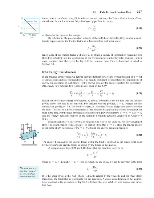
8.2 Fully Developed Laminar Flow 397 f 10 1 0.1 0.01 10 100 Laminar flow Re 1000 factor, which is defined to be f4. In this text we will use only the Darcy friction factor.2 Thus, the friction factor for laminar fully developed pipe flow is simply f 64 Re (8.19) as shown by the figure in the margin. By substituting the pressure drop in terms of the wall shear stress 1Eq. 8.52, we obtain an alternate expression for the friction factor as a dimensionless wall shear stress f 8t w rV 2 (8.20) Knowledge of the friction factor will allow us to obtain a variety of information regarding pipe flow. For turbulent flow the dependence of the friction factor on the Reynolds number is much more complex than that given by Eq. 8.19 for laminar flow. This is discussed in detail in Section 8.4. 8.2.4 Energy Considerations In the previous three sections we derived the basic laminar flow results from application of F ma or dimensional analysis considerations. It is equally important to understand the implications of energy considerations of such flows. To this end we consider the energy equation for incompressible, steady flow between two locations as is given in Eq. 5.89 p 1 g a 1 V 1 2 2g z 1 p 2 g a 2 V 2 2 2g z 2 h L (8.21) p 1 h L z 1 (1) p 2 (2) z 2 Recall that the kinetic energy coefficients, a 1 and a 2 , compensate for the fact that the velocity profile across the pipe is not uniform. For uniform velocity profiles, a 1, whereas for any nonuniform profile, a 7 1. The head loss term, h L , accounts for any energy loss associated with the flow. This loss is a direct consequence of the viscous dissipation that occurs throughout the fluid in the pipe. For the ideal 1inviscid2 cases discussed in previous chapters, a 1 a 2 1, h L 0, and the energy equation reduces to the familiar Bernoulli equation discussed in Chapter 3 1Eq. 3.72. Even though the velocity profile in viscous pipe flow is not uniform, for fully developed flow it does not change from section 112 to section 122 so that a 1 a 2 . Thus, the kinetic energy is the same at any section 1a 1 V 12 2 a 2 V 22 22 and the energy equation becomes a p 1 g z 1b a p 2 g z 2b h L (8.22) The energy dissipated by the viscous forces within the fluid is supplied by the excess work done by the pressure and gravity forces as shown by the figure in the margin. A comparison of Eqs. 8.22 and 8.10 shows that the head loss is given by h L 2t/ gr 1recall p 1 p 2 ¢p and z 2 z 1 / sin u2, which, by use of Eq. 8.4, can be rewritten in the form The head loss in a pipe is a result of the viscous shear stress on the wall. h L 4/t w gD (8.23) It is the shear stress at the wall 1which is directly related to the viscosity and the shear stress throughout the fluid2 that is responsible for the head loss. A closer consideration of the assumptions involved in the derivation of Eq. 8.23 will show that it is valid for both laminar and turbulent flow.
- Page 370 and 371: 346 Chapter 7 ■ Dimensional Analy
- Page 372 and 373: 348 Chapter 7 ■ Dimensional Analy
- Page 374 and 375: 350 Chapter 7 ■ Dimensional Analy
- Page 376 and 377: 352 Chapter 7 ■ Dimensional Analy
- Page 378 and 379: 354 Chapter 7 ■ Dimensional Analy
- Page 380 and 381: 356 Chapter 7 ■ Dimensional Analy
- Page 382 and 383: 358 Chapter 7 ■ Dimensional Analy
- Page 384 and 385: 360 Chapter 7 ■ Dimensional Analy
- Page 386 and 387: 362 Chapter 7 ■ Dimensional Analy
- Page 388 and 389: 364 Chapter 7 ■ Dimensional Analy
- Page 390 and 391: 366 Chapter 7 ■ Dimensional Analy
- Page 392 and 393: 368 Chapter 7 ■ Dimensional Analy
- Page 394 and 395: 370 Chapter 7 ■ Dimensional Analy
- Page 396 and 397: 372 Chapter 7 ■ Dimensional Analy
- Page 398 and 399: 374 Chapter 7 ■ Dimensional Analy
- Page 400 and 401: 376 Chapter 7 ■ Dimensional Analy
- Page 402 and 403: 378 Chapter 7 ■ Dimensional Analy
- Page 404 and 405: 380 Chapter 7 ■ Dimensional Analy
- Page 406 and 407: 382 Chapter 7 ■ Dimensional Analy
- Page 408 and 409: 384 Chapter 8 ■ Viscous Flow in P
- Page 410 and 411: 386 Chapter 8 ■ Viscous Flow in P
- Page 412 and 413: 388 Chapter 8 ■ Viscous Flow in P
- Page 414 and 415: 390 Chapter 8 ■ Viscous Flow in P
- Page 416 and 417: 392 Chapter 8 ■ Viscous Flow in P
- Page 418 and 419: 394 Chapter 8 ■ Viscous Flow in P
- Page 422 and 423: 398 Chapter 8 ■ Viscous Flow in P
- Page 424 and 425: 400 Chapter 8 ■ Viscous Flow in P
- Page 426 and 427: 402 Chapter 8 ■ Viscous Flow in P
- Page 428 and 429: 404 Chapter 8 ■ Viscous Flow in P
- Page 430 and 431: 406 Chapter 8 ■ Viscous Flow in P
- Page 432 and 433: 408 Chapter 8 ■ Viscous Flow in P
- Page 434 and 435: 410 Chapter 8 ■ Viscous Flow in P
- Page 436 and 437: 412 Chapter 8 ■ Viscous Flow in P
- Page 438 and 439: 414 Chapter 8 ■ Viscous Flow in P
- Page 440 and 441: 416 Chapter 8 ■ Viscous Flow in P
- Page 442 and 443: 418 Chapter 8 ■ Viscous Flow in P
- Page 444 and 445: 420 Chapter 8 ■ Viscous Flow in P
- Page 446 and 447: 422 Chapter 8 ■ Viscous Flow in P
- Page 448 and 449: 424 Chapter 8 ■ Viscous Flow in P
- Page 450 and 451: 426 Chapter 8 ■ Viscous Flow in P
- Page 452 and 453: 428 Chapter 8 ■ Viscous Flow in P
- Page 454 and 455: 430 Chapter 8 ■ Viscous Flow in P
- Page 456 and 457: 432 Chapter 8 ■ Viscous Flow in P
- Page 458 and 459: 434 Chapter 8 ■ Viscous Flow in P
- Page 460 and 461: 436 Chapter 8 ■ Viscous Flow in P
- Page 462 and 463: 438 Chapter 8 ■ Viscous Flow in P
- Page 464 and 465: 440 Chapter 8 ■ Viscous Flow in P
- Page 466 and 467: 442 Chapter 8 ■ Viscous Flow in P
- Page 468 and 469: 444 Chapter 8 ■ Viscous Flow in P
8.2 Fully Developed Laminar Flow 397<br />
f<br />
10<br />
1<br />
0.1<br />
0.01<br />
10 100<br />
Laminar flow<br />
Re<br />
1000<br />
factor, which is defined to be f4. In this text we will use only the Darcy friction factor.2 Thus,<br />
the friction factor for laminar fully developed pipe flow is simply<br />
f 64<br />
Re<br />
(8.19)<br />
as shown by the figure in the margin.<br />
By substituting the pressure drop in terms of the wall shear stress 1Eq. 8.52, we obtain an alternate<br />
expression for the friction factor as a dimensionless wall shear stress<br />
f 8t w<br />
rV 2<br />
(8.20)<br />
Knowledge of the friction factor will allow us to obtain a variety of information regarding pipe<br />
flow. For turbulent flow the dependence of the friction factor on the Reynolds number is much<br />
more complex than that given by Eq. 8.19 for laminar flow. This is discussed in detail in<br />
Section 8.4.<br />
8.2.4 Energy Considerations<br />
In the previous three sections we derived the basic laminar flow results from application of F ma<br />
or dimensional analysis considerations. It is equally important to understand the implications of<br />
energy considerations of such flows. To this end we consider the energy equation for incompressible,<br />
steady flow between two locations as is given in Eq. 5.89<br />
p 1<br />
g a 1 V 1 2<br />
2g z 1 p 2<br />
g a 2 V 2 2<br />
2g z 2 h L<br />
(8.21)<br />
p 1<br />
<br />
h L<br />
z 1<br />
(1)<br />
p 2 <br />
(2)<br />
z 2<br />
Recall that the kinetic energy coefficients, a 1 and a 2 , compensate for the fact that the velocity<br />
profile across the pipe is not uniform. For uniform velocity profiles, a 1, whereas for any<br />
nonuniform profile, a 7 1. The head loss term, h L , accounts for any energy loss associated with<br />
the flow. This loss is a direct consequence of the viscous dissipation that occurs throughout the<br />
<strong>fluid</strong> in the pipe. For the ideal 1inviscid2 cases discussed in previous chapters, a 1 a 2 1, h L 0,<br />
and the energy equation reduces to the familiar Bernoulli equation discussed in Chapter 3<br />
1Eq. 3.72.<br />
Even though the velocity profile in viscous pipe flow is not uniform, for fully developed<br />
flow it does not change from section 112 to section 122 so that a 1 a 2 . Thus, the kinetic energy<br />
is the same at any section 1a 1 V 12 2 a 2 V 22 22 and the energy equation becomes<br />
a p 1<br />
g z 1b a p 2<br />
g z 2b h L<br />
(8.22)<br />
The energy dissipated by the viscous forces within the <strong>fluid</strong> is supplied by the excess work done<br />
by the pressure and gravity forces as shown by the figure in the margin.<br />
A comparison of Eqs. 8.22 and 8.10 shows that the head loss is given by<br />
h L 2t/<br />
gr<br />
1recall p 1 p 2 ¢p and z 2 z 1 / sin u2, which, by use of Eq. 8.4, can be rewritten in the form<br />
The head loss in a<br />
pipe is a result of<br />
the viscous shear<br />
stress on the wall.<br />
h L 4/t w<br />
gD<br />
(8.23)<br />
It is the shear stress at the wall 1which is directly related to the viscosity and the shear stress<br />
throughout the <strong>fluid</strong>2 that is responsible for the head loss. A closer consideration of the assumptions<br />
involved in the derivation of Eq. 8.23 will show that it is valid for both laminar and turbulent<br />
flow.


