fluid_mechanics
316 Chapter 6 ■ Differential Analysis of Fluid Flow v z r o r r i z F I G U R E 6.35 The viscous flow through an annulus. An exact solution can be obtained for axial flow in the annular space between two fixed, concentric cylinders. 6.9.4 Steady, Axial, Laminar Flow in an Annulus r r . The differential equations 1Eqs. 6.143, 6.144, 6.1452 used in the preceding section for flow in a tube also apply to the axial flow in the annular space between two fixed, concentric cylinders 1Fig. 6.352. Equation 6.147 for the velocity distribution still applies, but for the stationary annulus the boundary conditions become v z 0 at r r o and v z 0 for With these two conditions the constants c 1 and c 2 i in Eq. 6.147 can be determined and the velocity distribution becomes v z 1 4m a 0p 0z b c r 2 r 2 o r 2 i r 2 o ln1r or i 2 ln r d r o (6.155) The corresponding volume rate of flow is r o Q v z 12pr2 dr p 8m a 0p 0z b c r 4 o r 4 i 1r 2 o r 2 i 2 2 d ln1r or i 2 r i or in terms of the pressure drop, ¢p, in length / of the annulus Q p¢p 8m/ c r 4 o r 4 i 1r 2 o r 2 i 2 2 d ln1r or i 2 (6.156) The velocity at any radial location within the annular space can be obtained from Eq. 6.155. The maximum velocity occurs at the radius r r m where 0v z 0r 0. Thus, r 2 o r 2 12 i r m c 2 ln1r or i 2 d (6.157) An inspection of this result shows that the maximum velocity does not occur at the midpoint of the annular space, but rather it occurs nearer the inner cylinder. The specific location depends on r o and r i . These results for flow through an annulus are valid only if the flow is laminar. A criterion based on the conventional Reynolds number 1which is defined in terms of the tube diameter2 cannot be directly applied to the annulus, since there are really “two” diameters involved. For tube cross sections other than simple circular tubes it is common practice to use an “effective” diameter, termed the hydraulic diameter, D h , which is defined as D h 4 cross-sectional area wetted perimeter The wetted perimeter is the perimeter in contact with the fluid. For an annulus D h 4p1r o 2 ri 2 2 21r o r i 2 2p1r o r i 2 In terms of the hydraulic diameter, the Reynolds number is Re rD h Vm 1where V Q cross-sectional area2, and it is commonly assumed that if this Reynolds number remains below 2100 the flow will be laminar. A further discussion of the concept of the hydraulic diameter as it applies to other noncircular cross sections is given in Section 8.4.3.
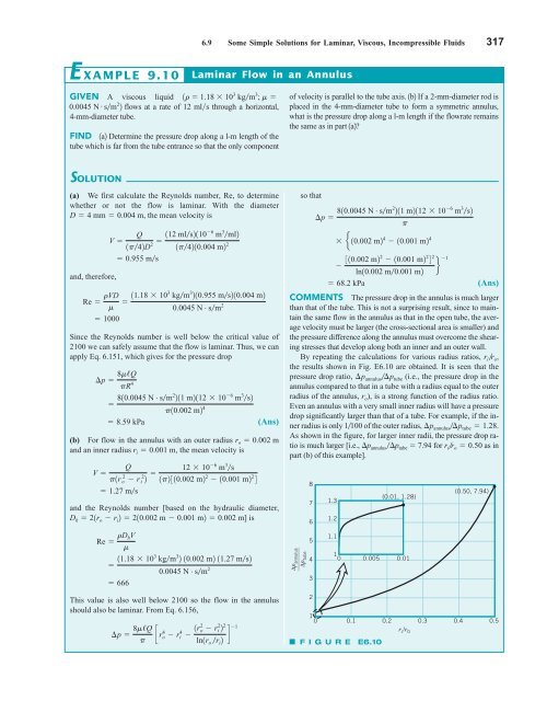
6.9 Some Simple Solutions for Laminar, Viscous, Incompressible Fluids 317 E XAMPLE 9.10 Laminar Flow in an Annulus GIVEN A viscous liquid 0.0045 N # 1r 1.18 10 3 kgm 3 ; m sm 2 2 flows at a rate of 12 mls through a horizontal, 4-mm-diameter tube. FIND 1a2 Determine the pressure drop along a l-m length of the tube which is far from the tube entrance so that the only component of velocity is parallel to the tube axis. 1b2 If a 2-mm-diameter rod is placed in the 4-mm-diameter tube to form a symmetric annulus, what is the pressure drop along a l-m length if the flowrate remains the same as in part 1a2? SOLUTION (a) We first calculate the Reynolds number, Re, to determine whether or not the flow is laminar. With the diameter D 4 mm 0.004 m, the mean velocity is and, therefore, Re rVD m 1000 V Q 1p42D 112 ml s2110 6 m 3 ml2 2 1p4210.004 m2 2 0.955 ms Since the Reynolds number is well below the critical value of 2100 we can safely assume that the flow is laminar. Thus, we can apply Eq. 6.151, which gives for the pressure drop ¢p 8m/Q pR 4 (Ans) (b) For flow in the annulus with an outer radius r o 0.002 m and an inner radius r i 0.001 m, the mean velocity is and the Reynolds number [based on the hydraulic diameter, D h 21r o r i 2 210.002 m 0.001 m2 0.002 m] is Re rD hV m 11.18 103 kgm 3 210.955 ms210.004 m2 0.0045 N # sm 2 810.0045 N # sm 2 211 m2112 10 6 m 3 s2 p10.002 m2 4 8.59 kPa Q V p1r o 2 r i 2 2 12 10 6 m 3 s 1p2310.002 m2 2 10.001 m2 2 4 1.27 ms 11.18 103 kgm 3 2 10.002 m2 11.27 ms2 0.0045 N # sm 2 666 This value is also well below 2100 so the flow in the annulus should also be laminar. From Eq. 6.156, ¢p 8m/Q p c r4 o r 4 i 1r 2 2 o r ln1r o r i 2 i 2 2 1 d so that ¢p 810.0045 N # sm 2 211 m2112 10 6 m 3 s2 p e10.002 m2 4 10.001 m2 4 310.002 m22 10.001 m2 2 4 2 1 f ln10.002 m0.001 m2 68.2 kPa (Ans) COMMENTS The pressure drop in the annulus is much larger than that of the tube. This is not a surprising result, since to maintain the same flow in the annulus as that in the open tube, the average velocity must be larger (the cross-sectional area is smaller) and the pressure difference along the annulus must overcome the shearing stresses that develop along both an inner and an outer wall. By repeating the calculations for various radius ratios, r ir o , the results shown in Fig. E6.10 are obtained. It is seen that the pressure drop ratio, ¢p annulus¢p tube (i.e., the pressure drop in the annulus compared to that in a tube with a radius equal to the outer radius of the annulus, r o ), is a strong function of the radius ratio. Even an annulus with a very small inner radius will have a pressure drop significantly larger than that of a tube. For example, if the inner radius is only 1100 of the outer radius, ¢p annulus¢p tube 1.28. As shown in the figure, for larger inner radii, the pressure drop ratio is much larger [i.e., p annulus p tube 7.94 for r ir o 0.50 as in part (b) of this example]. ________ Δp annulus Δp tube 8 7 6 5 4 3 2 1.3 1.2 1.1 1 0 0.005 0.01 F I G U R E E6.10 (0.01, 1.28) (0.50, 7.94) 1 0 0.1 0.2 0.3 0.4 0.5 r i /r 0
- Page 290 and 291: ) 266 Chapter 6 ■ Differential An
- Page 292 and 293: 268 Chapter 6 ■ Differential Anal
- Page 294 and 295: 270 Chapter 6 ■ Differential Anal
- Page 296 and 297: 272 Chapter 6 ■ Differential Anal
- Page 298 and 299: 274 Chapter 6 ■ Differential Anal
- Page 300 and 301: 276 Chapter 6 ■ Differential Anal
- Page 302 and 303: 278 Chapter 6 ■ Differential Anal
- Page 304 and 305: 280 Chapter 6 ■ Differential Anal
- Page 306 and 307: 282 Chapter 6 ■ Differential Anal
- Page 308 and 309: 284 Chapter 6 ■ Differential Anal
- Page 310 and 311: 286 Chapter 6 ■ Differential Anal
- Page 312 and 313: 288 Chapter 6 ■ Differential Anal
- Page 314 and 315: 290 Chapter 6 ■ Differential Anal
- Page 316 and 317: 292 Chapter 6 ■ Differential Anal
- Page 318 and 319: 294 Chapter 6 ■ Differential Anal
- Page 320 and 321: 296 Chapter 6 ■ Differential Anal
- Page 322 and 323: 298 Chapter 6 ■ Differential Anal
- Page 324 and 325: 300 Chapter 6 ■ Differential Anal
- Page 326 and 327: 302 Chapter 6 ■ Differential Anal
- Page 328 and 329: 304 Chapter 6 ■ Differential Anal
- Page 330 and 331: 306 Chapter 6 ■ Differential Anal
- Page 332 and 333: 308 Chapter 6 ■ Differential Anal
- Page 334 and 335: 310 Chapter 6 ■ Differential Anal
- Page 336 and 337: 312 Chapter 6 ■ Differential Anal
- Page 338 and 339: 314 Chapter 6 ■ Differential Anal
- Page 342 and 343: 318 Chapter 6 ■ Differential Anal
- Page 344 and 345: 320 Chapter 6 ■ Differential Anal
- Page 346 and 347: 322 Chapter 6 ■ Differential Anal
- Page 348 and 349: 324 Chapter 6 ■ Differential Anal
- Page 350 and 351: 326 Chapter 6 ■ Differential Anal
- Page 352 and 353: 328 Chapter 6 ■ Differential Anal
- Page 354 and 355: 330 Chapter 6 ■ Differential Anal
- Page 356 and 357: 7 Dimensional Analysis, Similitude,
- Page 358 and 359: 334 Chapter 7 ■ Dimensional Analy
- Page 360 and 361: 336 Chapter 7 ■ Dimensional Analy
- Page 362 and 363: 338 Chapter 7 ■ Dimensional Analy
- Page 364 and 365: 340 Chapter 7 ■ Dimensional Analy
- Page 366 and 367: 342 Chapter 7 ■ Dimensional Analy
- Page 368 and 369: 344 Chapter 7 ■ Dimensional Analy
- Page 370 and 371: 346 Chapter 7 ■ Dimensional Analy
- Page 372 and 373: 348 Chapter 7 ■ Dimensional Analy
- Page 374 and 375: 350 Chapter 7 ■ Dimensional Analy
- Page 376 and 377: 352 Chapter 7 ■ Dimensional Analy
- Page 378 and 379: 354 Chapter 7 ■ Dimensional Analy
- Page 380 and 381: 356 Chapter 7 ■ Dimensional Analy
- Page 382 and 383: 358 Chapter 7 ■ Dimensional Analy
- Page 384 and 385: 360 Chapter 7 ■ Dimensional Analy
- Page 386 and 387: 362 Chapter 7 ■ Dimensional Analy
- Page 388 and 389: 364 Chapter 7 ■ Dimensional Analy
6.9 Some Simple Solutions for Laminar, Viscous, Incompressible Fluids 317<br />
E XAMPLE 9.10<br />
Laminar Flow in an Annulus<br />
GIVEN A viscous liquid<br />
0.0045 N # 1r 1.18 10 3 kgm 3 ; m <br />
sm 2 2 flows at a rate of 12 mls through a horizontal,<br />
4-mm-diameter tube.<br />
FIND 1a2 Determine the pressure drop along a l-m length of the<br />
tube which is far from the tube entrance so that the only component<br />
of velocity is parallel to the tube axis. 1b2 If a 2-mm-diameter rod is<br />
placed in the 4-mm-diameter tube to form a symmetric annulus,<br />
what is the pressure drop along a l-m length if the flowrate remains<br />
the same as in part 1a2?<br />
SOLUTION<br />
(a) We first calculate the Reynolds number, Re, to determine<br />
whether or not the flow is laminar. With the diameter<br />
D 4 mm 0.004 m, the mean velocity is<br />
and, therefore,<br />
Re rVD<br />
m<br />
1000<br />
V <br />
Q<br />
1p42D 112 ml s2110 6 m 3 ml2<br />
2 1p4210.004 m2 2<br />
0.955 ms<br />
Since the Reynolds number is well below the critical value of<br />
2100 we can safely assume that the flow is laminar. Thus, we can<br />
apply Eq. 6.151, which gives for the pressure drop<br />
¢p 8m/Q<br />
pR 4<br />
(Ans)<br />
(b) For flow in the annulus with an outer radius r o 0.002 m<br />
and an inner radius r i 0.001 m, the mean velocity is<br />
and the Reynolds number [based on the hydraulic diameter,<br />
D h 21r o r i 2 210.002 m 0.001 m2 0.002 m] is<br />
Re rD hV<br />
m<br />
11.18 103 kgm 3 210.955 ms210.004 m2<br />
0.0045 N # sm 2<br />
810.0045 N # sm 2 211 m2112 10 6 m 3 s2<br />
p10.002 m2 4<br />
8.59 kPa<br />
Q<br />
V <br />
p1r o 2 r i 2 2 12 10 6 m 3 s<br />
1p2310.002 m2 2 10.001 m2 2 4<br />
1.27 ms<br />
11.18 103 kgm 3 2 10.002 m2 11.27 ms2<br />
0.0045 N # sm 2<br />
666<br />
This value is also well below 2100 so the flow in the annulus<br />
should also be laminar. From Eq. 6.156,<br />
¢p 8m/Q<br />
p<br />
c r4 o r 4 i 1r 2 2<br />
o r<br />
ln1r o r i 2<br />
i 2 2<br />
1<br />
d<br />
so that<br />
¢p 810.0045 N # sm 2 211 m2112 10 6 m 3 s2<br />
p<br />
e10.002 m2 4 10.001 m2 4<br />
310.002 m22 10.001 m2 2 4 2 1<br />
f<br />
ln10.002 m0.001 m2<br />
68.2 kPa<br />
(Ans)<br />
COMMENTS The pressure drop in the annulus is much larger<br />
than that of the tube. This is not a surprising result, since to maintain<br />
the same flow in the annulus as that in the open tube, the average<br />
velocity must be larger (the cross-sectional area is smaller) and<br />
the pressure difference along the annulus must overcome the shearing<br />
stresses that develop along both an inner and an outer wall.<br />
By repeating the calculations for various radius ratios, r ir o ,<br />
the results shown in Fig. E6.10 are obtained. It is seen that the<br />
pressure drop ratio, ¢p annulus¢p tube (i.e., the pressure drop in the<br />
annulus compared to that in a tube with a radius equal to the outer<br />
radius of the annulus, r o ), is a strong function of the radius ratio.<br />
Even an annulus with a very small inner radius will have a pressure<br />
drop significantly larger than that of a tube. For example, if the inner<br />
radius is only 1100 of the outer radius, ¢p annulus¢p tube 1.28.<br />
As shown in the figure, for larger inner radii, the pressure drop ratio<br />
is much larger [i.e., p annulus p tube 7.94 for r ir o 0.50 as in<br />
part (b) of this example].<br />
________<br />
Δp annulus<br />
Δp tube<br />
8<br />
7<br />
6<br />
5<br />
4<br />
3<br />
2<br />
1.3<br />
1.2<br />
1.1<br />
1<br />
0 0.005 0.01<br />
F I G U R E E6.10<br />
(0.01, 1.28)<br />
(0.50, 7.94)<br />
1 0 0.1 0.2 0.3 0.4 0.5<br />
r i /r 0


