fluid_mechanics
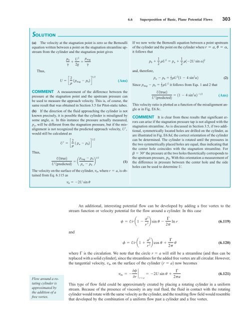
302 Chapter 6 ■ Differential Analysis of Fluid Flow y dθ p s F y a F x θ x F I G U R E 6.28 on a circular cylinder. The notation for determining lift and drag V6.9 Potential and viscous flow Potential theory incorrectly predicts that the drag on a cylinder is zero. and F x 2p F y p s sin u a du 0 (6.118) where is the drag 1force parallel to direction of the uniform flow2 and is the lift 1force perpendicular to the direction of the uniform flow2. Substitution for p s from Eq. 6.116 into these two equations, and subsequent integration, reveals that F x 0 and F y 0 1Problem 6.732. These results indicate that both the drag and lift as predicted by potential theory for a fixed cylinder in a uniform stream are zero. Since the pressure distribution is symmetrical around the cylinder, this is not really a surprising result. However, we know from experience that there is a significant drag developed on a cylinder when it is placed in a moving fluid. This discrepancy is known as d’Alembert’s paradox. The paradox is named after Jean le Rond d’Alembert 11717–17832, a French mathematician and philosopher, who first showed that the drag on bodies immersed in inviscid fluids is zero. It was not until the latter part of the nineteenth century and the early part of the twentieth century that the role viscosity plays in the steady fluid motion was understood and d’Alembert’s paradox explained 1see Section 9.12. F y E XAMPLE 6.8 Potential Flow—Cylinder GIVEN When a circular cylinder is placed in a uniform stream, a stagnation point is created on the cylinder as is shown in Fig. E6.8a. If a small hole is located at this point, the stagnation pressure, p stag , can be measured and used to determine the approach velocity, U. FIND (a) Show how p stag and U are related. (b) If the cylinder is misaligned by an angle (Figure E6.8b), but the measured pressure is still interpreted as the stagnation pressure, determine an expression for the ratio of the true velocity, U, to the predicted velocity, U. Plot this ratio as a function of for the range 20 20. U U U p 0 y a r θ x α a β β Stagnation point (a) (b) (d) U__ U' 1.5 1.4 1.3 1.2 1.1 1.0 –20° –10° 0° 10° 20° α (c) F I G U R E E6.8
6.6 Superposition of Basic, Plane Potential Flows 303 SOLUTION (a) The velocity at the stagnation point is zero so the Bernoulli equation written between a point on the stagnation streamline upstream from the cylinder and the stagnation point gives Thus, (Ans) COMMENT A measurement of the difference between the pressure at the stagnation point and the upstream pressure can be used to measure the approach velocity. This is, of course, the same result that was obtained in Section 3.5 for Pitot-static tubes. (b) If the direction of the fluid approaching the cylinder is not known precisely, it is possible that the cylinder is misaligned by some angle, a. In this instance the pressure actually measured, p a , will be different from the stagnation pressure, but if the misalignment is not recognized the predicted approach velocity, U¿, would still be calculated as Thus, p 0 g U 2 2g p stag g U c 2 12 r 1 p stag p 0 2d U¿ c 2 12 r 1 p a p 0 2d U1true2 U¿1predicted2 ap stag p 12 0 b p a p 0 The velocity on the surface of the cylinder, v u , where r a, is obtained from Eq. 6.115 as v u 2U sin u (1) If we now write the Bernoulli equation between a point upstream of the cylinder and the point on the cylinder where r a, u a, it follows that p 0 1 2 rU 2 p a 1 2 r12U sin a22 and, therefore, p a p 0 1 2 rU 2 11 4 sin 2 a2 Since p stag p 0 1 2 rU 2 it follows from Eqs. 1 and 2 that U1true2 U¿1predicted2 11 4 sin2 a2 1 2 (2) (Ans) This velocity ratio is plotted as a function of the misalignment angle a in Fig. E6.8c. COMMENT It is clear from these results that significant errors can arise if the stagnation pressure tap is not aligned with the stagnation streamline. As is discussed in Section 3.5, if two additional, symmetrically located holes are drilled on the cylinder, as are illustrated in Fig. E6.8d, the correct orientation of the cylinder can be determined. The cylinder is rotated until the pressures in the two symmetrically placed holes are equal, thus indicating that the center hole coincides with the stagnation streamline. For b 30° the pressure at the two holes theoretically corresponds to the upstream pressure, p 0 . With this orientation a measurement of the difference in pressure between the center hole and the side holes can be used to determine U. An additional, interesting potential flow can be developed by adding a free vortex to the stream function or velocity potential for the flow around a cylinder. In this case c Ur a1 a2 r 2b sin u 2p ln r (6.119) and f Ur a1 a2 r 2b cos u 2p u (6.120) Flow around a rotating cylinder is approximated by the addition of a free vortex. where is the circulation. We note that the circle r a will still be a streamline 1and thus can be replaced with a solid cylinder2, since the streamlines for the added free vortex are all circular. However, the tangential velocity, v u , on the surface of the cylinder 1r a2 now becomes v us 0c 0r ` 2U sin u ra 2pa (6.121) This type of flow field could be approximately created by placing a rotating cylinder in a uniform stream. Because of the presence of viscosity in any real fluid, the fluid in contact with the rotating cylinder would rotate with the same velocity as the cylinder, and the resulting flow field would resemble that developed by the combination of a uniform flow past a cylinder and a free vortex.
- Page 276 and 277: 252 Chapter 5 ■ Finite Control Vo
- Page 278 and 279: 254 Chapter 5 ■ Finite Control Vo
- Page 280 and 281: 256 Chapter 5 ■ Finite Control Vo
- Page 282 and 283: 258 Chapter 5 ■ Finite Control Vo
- Page 284 and 285: 260 Chapter 5 ■ Finite Control Vo
- Page 286 and 287: 262 Chapter 5 ■ Finite Control Vo
- Page 288 and 289: 264 Chapter 6 ■ Differential Anal
- Page 290 and 291: ) 266 Chapter 6 ■ Differential An
- Page 292 and 293: 268 Chapter 6 ■ Differential Anal
- Page 294 and 295: 270 Chapter 6 ■ Differential Anal
- Page 296 and 297: 272 Chapter 6 ■ Differential Anal
- Page 298 and 299: 274 Chapter 6 ■ Differential Anal
- Page 300 and 301: 276 Chapter 6 ■ Differential Anal
- Page 302 and 303: 278 Chapter 6 ■ Differential Anal
- Page 304 and 305: 280 Chapter 6 ■ Differential Anal
- Page 306 and 307: 282 Chapter 6 ■ Differential Anal
- Page 308 and 309: 284 Chapter 6 ■ Differential Anal
- Page 310 and 311: 286 Chapter 6 ■ Differential Anal
- Page 312 and 313: 288 Chapter 6 ■ Differential Anal
- Page 314 and 315: 290 Chapter 6 ■ Differential Anal
- Page 316 and 317: 292 Chapter 6 ■ Differential Anal
- Page 318 and 319: 294 Chapter 6 ■ Differential Anal
- Page 320 and 321: 296 Chapter 6 ■ Differential Anal
- Page 322 and 323: 298 Chapter 6 ■ Differential Anal
- Page 324 and 325: 300 Chapter 6 ■ Differential Anal
- Page 328 and 329: 304 Chapter 6 ■ Differential Anal
- Page 330 and 331: 306 Chapter 6 ■ Differential Anal
- Page 332 and 333: 308 Chapter 6 ■ Differential Anal
- Page 334 and 335: 310 Chapter 6 ■ Differential Anal
- Page 336 and 337: 312 Chapter 6 ■ Differential Anal
- Page 338 and 339: 314 Chapter 6 ■ Differential Anal
- Page 340 and 341: 316 Chapter 6 ■ Differential Anal
- Page 342 and 343: 318 Chapter 6 ■ Differential Anal
- Page 344 and 345: 320 Chapter 6 ■ Differential Anal
- Page 346 and 347: 322 Chapter 6 ■ Differential Anal
- Page 348 and 349: 324 Chapter 6 ■ Differential Anal
- Page 350 and 351: 326 Chapter 6 ■ Differential Anal
- Page 352 and 353: 328 Chapter 6 ■ Differential Anal
- Page 354 and 355: 330 Chapter 6 ■ Differential Anal
- Page 356 and 357: 7 Dimensional Analysis, Similitude,
- Page 358 and 359: 334 Chapter 7 ■ Dimensional Analy
- Page 360 and 361: 336 Chapter 7 ■ Dimensional Analy
- Page 362 and 363: 338 Chapter 7 ■ Dimensional Analy
- Page 364 and 365: 340 Chapter 7 ■ Dimensional Analy
- Page 366 and 367: 342 Chapter 7 ■ Dimensional Analy
- Page 368 and 369: 344 Chapter 7 ■ Dimensional Analy
- Page 370 and 371: 346 Chapter 7 ■ Dimensional Analy
- Page 372 and 373: 348 Chapter 7 ■ Dimensional Analy
- Page 374 and 375: 350 Chapter 7 ■ Dimensional Analy
6.6 Superposition of Basic, Plane Potential Flows 303<br />
SOLUTION<br />
(a) The velocity at the stagnation point is zero so the Bernoulli<br />
equation written between a point on the stagnation streamline upstream<br />
from the cylinder and the stagnation point gives<br />
Thus,<br />
(Ans)<br />
COMMENT A measurement of the difference between the<br />
pressure at the stagnation point and the upstream pressure can<br />
be used to measure the approach velocity. This is, of course, the<br />
same result that was obtained in Section 3.5 for Pitot-static tubes.<br />
(b) If the direction of the <strong>fluid</strong> approaching the cylinder is not<br />
known precisely, it is possible that the cylinder is misaligned by<br />
some angle, a. In this instance the pressure actually measured,<br />
p a , will be different from the stagnation pressure, but if the misalignment<br />
is not recognized the predicted approach velocity, U¿,<br />
would still be calculated as<br />
Thus,<br />
p 0<br />
g U 2<br />
2g p stag<br />
g<br />
U c 2 12<br />
r 1 p stag p 0 2d<br />
U¿ c 2 12<br />
r 1 p a p 0 2d<br />
U1true2<br />
U¿1predicted2 ap stag p 12 0<br />
b<br />
p a p 0<br />
The velocity on the surface of the cylinder, v u , where r a, is obtained<br />
from Eq. 6.115 as<br />
v u 2U sin u<br />
(1)<br />
If we now write the Bernoulli equation between a point upstream<br />
of the cylinder and the point on the cylinder where r a, u a,<br />
it follows that<br />
p 0 1 2 rU 2 p a 1 2 r12U sin a22<br />
and, therefore,<br />
p a p 0 1 2 rU 2 11 4 sin 2 a2<br />
Since p stag p 0 1 2 rU 2 it follows from Eqs. 1 and 2 that<br />
U1true2<br />
U¿1predicted2 11 4 sin2 a2 1 2<br />
(2)<br />
(Ans)<br />
This velocity ratio is plotted as a function of the misalignment angle<br />
a in Fig. E6.8c.<br />
COMMENT It is clear from these results that significant errors<br />
can arise if the stagnation pressure tap is not aligned with the<br />
stagnation streamline. As is discussed in Section 3.5, if two additional,<br />
symmetrically located holes are drilled on the cylinder, as<br />
are illustrated in Fig. E6.8d, the correct orientation of the cylinder<br />
can be determined. The cylinder is rotated until the pressures in<br />
the two symmetrically placed holes are equal, thus indicating that<br />
the center hole coincides with the stagnation streamline. For<br />
b 30° the pressure at the two holes theoretically corresponds to<br />
the upstream pressure, p 0 . With this orientation a measurement of<br />
the difference in pressure between the center hole and the side<br />
holes can be used to determine U.<br />
An additional, interesting potential flow can be developed by adding a free vortex to the<br />
stream function or velocity potential for the flow around a cylinder. In this case<br />
c Ur a1 a2 <br />
r 2b sin u <br />
2p ln r<br />
(6.119)<br />
and<br />
f Ur a1 a2 <br />
r<br />
2b cos u <br />
2p u<br />
(6.120)<br />
Flow around a rotating<br />
cylinder is<br />
approximated by<br />
the addition of a<br />
free vortex.<br />
where is the circulation. We note that the circle r a will still be a streamline 1and thus can be<br />
replaced with a solid cylinder2, since the streamlines for the added free vortex are all circular. However,<br />
the tangential velocity, v u , on the surface of the cylinder 1r a2 now becomes<br />
v us 0c<br />
0r ` 2U sin u <br />
<br />
ra<br />
2pa<br />
(6.121)<br />
This type of flow field could be approximately created by placing a rotating cylinder in a uniform<br />
stream. Because of the presence of viscosity in any real <strong>fluid</strong>, the <strong>fluid</strong> in contact with the rotating<br />
cylinder would rotate with the same velocity as the cylinder, and the resulting flow field would resemble<br />
that developed by the combination of a uniform flow past a cylinder and a free vortex.


