fluid_mechanics
124 Chapter 3 ■ Elementary Fluid Dynamics—The Bernoulli Equation V 1 2 /2g V 2 /2g p 2 / γ Energy line (EL) 2 V___ 2 2g Hydraulic grade line (HGL) p/ γ H Static p 1 / γ z 2 z Q z 1 Stagnation F I G U R E 3.21 hydraulic grade line. Datum Representation of the energy line and the V 2 /2g p/ z H Under the assumptions of the Bernoulli equation, the energy line is horizontal. Each of the terms in this equation has the units of length 1feet or meters2 and represents a certain type of head. The Bernoulli equation states that the sum of the pressure head, the velocity head, and the elevation head is constant along a streamline. This constant is called the total head, H. The energy line is a line that represents the total head available to the fluid. As shown in Fig. 3.21, the elevation of the energy line can be obtained by measuring the stagnation pressure with a Pitot tube. 1A Pitot tube is the portion of a Pitot-static tube that measures the stagnation pressure. See Section 3.5.2 The stagnation point at the end of the Pitot tube provides a measurement of the total head 1or energy2 of the flow. The static pressure tap connected to the piezometer tube shown, on the other hand, measures the sum of the pressure head and the elevation head, pg z. This sum is often called the piezometric head. The static pressure tap does not measure the velocity head. According to Eq. 3.22, the total head remains constant along the streamline 1provided the assumptions of the Bernoulli equation are valid2. Thus, a Pitot tube at any other location in the flow will measure the same total head, as is shown in the figure. The elevation head, velocity head, and pressure head may vary along the streamline, however. The locus of elevations provided by a series of Pitot tubes is termed the energy line, EL. The locus provided by a series of piezometer taps is termed the hydraulic grade line, HGL. Under the assumptions of the Bernoulli equation, the energy line is horizontal. If the fluid velocity changes along the streamline, the hydraulic grade line will not be horizontal. If viscous effects are important 1as they often are in pipe flows2, the total head does not remain constant due to a loss in energy as the fluid flows along its streamline. This means that the energy line is no longer horizontal. Such viscous effects are discussed in Chapters 5 and 8. The energy line and hydraulic grade line for flow from a large tank are shown in Fig. 3.22. If the flow is steady, incompressible, and inviscid, the energy line is horizontal and at the elevation of the liquid in the tank 1since the fluid velocity in the tank and the pressure on the surface V 1 = p 1 = 0 (1) p__ 2 H = z γ 1 V 2 2 ___ 2g HGL V 3 2 ___ 2g EL p 3 = 0 (2) z 2 z 3 (3) F I G U R E 3.22 The energy line and hydraulic grade line for flow from a tank.
3.7 The Energy Line and the Hydraulic Grade Line 125 Q p > 0 p < 0 p/ γ z z p/γ V 2 __ 2g EL HGL F I G U R E 3.23 Use of the energy line and the hydraulic grade line. For flow below (above) the hydraulic grade line, the pressure is positive (negative). are zero2. The hydraulic grade line lies a distance of one velocity head, V 2 2g, below the energy line. Thus, a change in fluid velocity due to a change in the pipe diameter results in a change in the elevation of the hydraulic grade line. At the pipe outlet the pressure head is zero 1gage2 so the pipe elevation and the hydraulic grade line coincide. The distance from the pipe to the hydraulic grade line indicates the pressure within the pipe, as is shown in Fig. 3.23. If the pipe lies below the hydraulic grade line, the pressure within the pipe is positive 1above atmospheric2. If the pipe lies above the hydraulic grade line, the pressure is negative 1below atmospheric2. Thus, a scale drawing of a pipeline and the hydraulic grade line can be used to readily indicate regions of positive or negative pressure within a pipe. E XAMPLE 3.14 Energy Line and Hydraulic Grade Line GIVEN Water is siphoned from the tank shown in Fig. E3.14 through a hose of constant diameter. A small hole is found in the hose at location 112 as indicated. (1) HGL with valve closed and EL with valve open or closed FIND When the siphon is used, will water leak out of the hose, or will air leak into the hose, thereby possibly causing the siphon to malfunction? V 2 __ 2g z p _γ SOLUTION Valve HGL with valve open Whether air will leak into or water will leak out of the hose depends on whether the pressure within the hose at 112 is less than or greater than atmospheric. Which happens can be easily determined by using the energy line and hydraulic grade line concepts. With the assumption of steady, incompressible, inviscid flow it follows that the total head is constant—thus, the energy line is horizontal. Since the hose diameter is constant, it follows from the continuity equation 1AV constant2 that the water velocity in the hose is constant throughout. Thus, the hydraulic grade line is a constant distance, V 2 2g, below the energy line as shown in Fig. E3.14. Since the pressure at the end of the hose is atmospheric, it follows that the hydraulic grade line is at the same elevation as the end of the hose outlet. The fluid within the hose at any point above the hydraulic grade line will be at less than atmospheric pressure. Thus, air will leak into the hose through the hole at point 112. (Ans) F I G U R E E3.14 COMMENT In practice, viscous effects may be quite important, making this simple analysis 1horizontal energy line2 incorrect. However, if the hose is “not too small diameter,” “not too long,” the fluid “not too viscous,” and the flowrate “not too large,” the above result may be very accurate. If any of these assumptions are relaxed, a more detailed analysis is required 1see Chapter 82. If the end of the hose were closed so that the flowrate were zero, the hydraulic grade line would coincide with the energy line 1V 2 2g 0 throughout2, the pressure at 112 would be greater than atmospheric, and water would leak through the hole at 112. The above discussion of the hydraulic grade line and the energy line is restricted to ideal situations involving inviscid, incompressible flows. Another restriction is that there are no “sources” or “sinks” of energy within the flow field. That is, there are no pumps or turbines involved. Alterations in the energy line and hydraulic grade line concepts due to these devices are discussed in Chapters 5 and 8.
- Page 98 and 99: 74 Chapter 2 ■ Fluid Statics The
- Page 100 and 101: 76 Chapter 2 ■ Fluid Statics z p
- Page 102 and 103: 78 Chapter 2 ■ Fluid Statics dete
- Page 104 and 105: 80 Chapter 2 ■ Fluid Statics Sect
- Page 106 and 107: 82 Chapter 2 ■ Fluid Statics Vapo
- Page 108 and 109: 84 Chapter 2 ■ Fluid Statics heig
- Page 110 and 111: 86 Chapter 2 ■ Fluid Statics h 4
- Page 112 and 113: 88 Chapter 2 ■ Fluid Statics 2.81
- Page 114 and 115: 90 Chapter 2 ■ Fluid Statics h 2
- Page 116 and 117: 92 Chapter 2 ■ Fluid Statics 2.12
- Page 118 and 119: 94 Chapter 3 ■ Elementary Fluid D
- Page 120 and 121: 96 Chapter 3 ■ Elementary Fluid D
- Page 122 and 123: 98 Chapter 3 ■ Elementary Fluid D
- Page 124 and 125: 100 Chapter 3 ■ Elementary Fluid
- Page 126 and 127: 102 Chapter 3 ■ Elementary Fluid
- Page 128 and 129: 104 Chapter 3 ■ Elementary Fluid
- Page 130 and 131: 106 Chapter 3 ■ Elementary Fluid
- Page 132 and 133: 108 Chapter 3 ■ Elementary Fluid
- Page 134 and 135: 110 Chapter 3 ■ Elementary Fluid
- Page 136 and 137: 112 Chapter 3 ■ Elementary Fluid
- Page 138 and 139: 114 Chapter 3 ■ Elementary Fluid
- Page 140 and 141: 116 Chapter 3 ■ Elementary Fluid
- Page 142 and 143: 118 Chapter 3 ■ Elementary Fluid
- Page 144 and 145: 120 Chapter 3 ■ Elementary Fluid
- Page 146 and 147: 122 Chapter 3 ■ Elementary Fluid
- Page 150 and 151: 126 Chapter 3 ■ Elementary Fluid
- Page 152 and 153: 128 Chapter 3 ■ Elementary Fluid
- Page 154 and 155: 130 Chapter 3 ■ Elementary Fluid
- Page 156 and 157: 132 Chapter 3 ■ Elementary Fluid
- Page 158 and 159: 134 Chapter 3 ■ Elementary Fluid
- Page 160 and 161: 136 Chapter 3 ■ Elementary Fluid
- Page 162 and 163: 138 Chapter 3 ■ Elementary Fluid
- Page 164 and 165: 140 Chapter 3 ■ Elementary Fluid
- Page 166 and 167: 142 Chapter 3 ■ Elementary Fluid
- Page 168 and 169: 144 Chapter 3 ■ Elementary Fluid
- Page 170 and 171: 146 Chapter 3 ■ Elementary Fluid
- Page 172 and 173: 148 Chapter 4 ■ Fluid Kinematics
- Page 174 and 175: 150 Chapter 4 ■ Fluid Kinematics
- Page 176 and 177: 152 Chapter 4 ■ Fluid Kinematics
- Page 178 and 179: 154 Chapter 4 ■ Fluid Kinematics
- Page 180 and 181: 156 Chapter 4 ■ Fluid Kinematics
- Page 182 and 183: 158 Chapter 4 ■ Fluid Kinematics
- Page 184 and 185: 160 Chapter 4 ■ Fluid Kinematics
- Page 186 and 187: 162 Chapter 4 ■ Fluid Kinematics
- Page 188 and 189: 164 Chapter 4 ■ Fluid Kinematics
- Page 190 and 191: 166 Chapter 4 ■ Fluid Kinematics
- Page 192 and 193: 168 Chapter 4 ■ Fluid Kinematics
- Page 194 and 195: 170 Chapter 4 ■ Fluid Kinematics
- Page 196 and 197: 172 Chapter 4 ■ Fluid Kinematics
124 Chapter 3 ■ Elementary Fluid Dynamics—The Bernoulli Equation<br />
V 1 2 /2g<br />
V 2 /2g<br />
p 2 / γ<br />
Energy line (EL)<br />
2<br />
V___<br />
2<br />
2g<br />
Hydraulic<br />
grade line (HGL)<br />
p/ γ<br />
H<br />
Static<br />
p 1 / γ<br />
z 2<br />
z<br />
Q<br />
z 1<br />
Stagnation<br />
F I G U R E 3.21<br />
hydraulic grade line.<br />
Datum<br />
Representation of the energy line and the<br />
V 2 /2g<br />
p/<br />
z<br />
H<br />
Under the assumptions<br />
of the Bernoulli<br />
equation, the energy<br />
line is horizontal.<br />
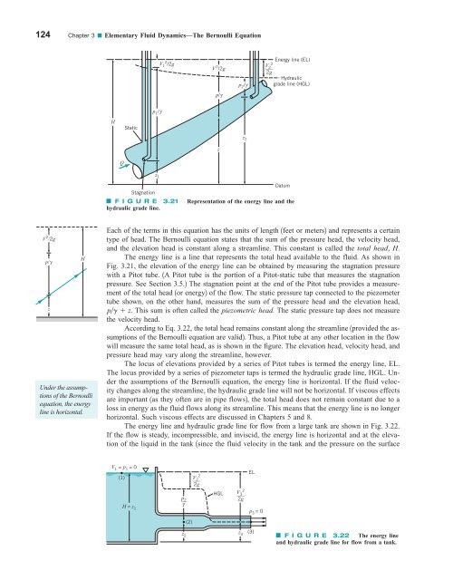
Each of the terms in this equation has the units of length 1feet or meters2 and represents a certain<br />
type of head. The Bernoulli equation states that the sum of the pressure head, the velocity head,<br />
and the elevation head is constant along a streamline. This constant is called the total head, H.<br />
The energy line is a line that represents the total head available to the <strong>fluid</strong>. As shown in<br />
Fig. 3.21, the elevation of the energy line can be obtained by measuring the stagnation pressure<br />
with a Pitot tube. 1A Pitot tube is the portion of a Pitot-static tube that measures the stagnation<br />
pressure. See Section 3.5.2 The stagnation point at the end of the Pitot tube provides a measurement<br />
of the total head 1or energy2 of the flow. The static pressure tap connected to the piezometer<br />
tube shown, on the other hand, measures the sum of the pressure head and the elevation head,<br />
pg z. This sum is often called the piezometric head. The static pressure tap does not measure<br />
the velocity head.<br />
According to Eq. 3.22, the total head remains constant along the streamline 1provided the assumptions<br />
of the Bernoulli equation are valid2. Thus, a Pitot tube at any other location in the flow<br />
will measure the same total head, as is shown in the figure. The elevation head, velocity head, and<br />
pressure head may vary along the streamline, however.<br />
The locus of elevations provided by a series of Pitot tubes is termed the energy line, EL.<br />
The locus provided by a series of piezometer taps is termed the hydraulic grade line, HGL. Under<br />
the assumptions of the Bernoulli equation, the energy line is horizontal. If the <strong>fluid</strong> velocity<br />
changes along the streamline, the hydraulic grade line will not be horizontal. If viscous effects<br />
are important 1as they often are in pipe flows2, the total head does not remain constant due to a<br />
loss in energy as the <strong>fluid</strong> flows along its streamline. This means that the energy line is no longer<br />
horizontal. Such viscous effects are discussed in Chapters 5 and 8.<br />
The energy line and hydraulic grade line for flow from a large tank are shown in Fig. 3.22.<br />
If the flow is steady, incompressible, and inviscid, the energy line is horizontal and at the elevation<br />
of the liquid in the tank 1since the <strong>fluid</strong> velocity in the tank and the pressure on the surface<br />
V 1 = p 1 = 0<br />
(1)<br />
p__<br />
2<br />
H = z<br />
γ<br />
1<br />
V 2<br />
2<br />
___<br />
2g<br />
HGL<br />
V 3<br />
2<br />
___<br />
2g<br />
EL<br />
p 3 = 0<br />
(2)<br />
z 2<br />
z 3<br />
(3)<br />
F I G U R E 3.22 The energy line<br />
and hydraulic grade line for flow from a tank.


