HEULE Full Catalog
HEULE is the industry leader in providing automated front and back deburring, chamfering, spotfacing, drilling, and countersinking tools for CNC machining. HEULE tools are found on the production lines of major manufacturers across all industries including automotive, aerospace, heavy construction, and medical. HEULE is the industry leader in providing automated front and back deburring, chamfering, spotfacing, drilling, and countersinking tools for CNC machining. HEULE tools are found on the production lines of major manufacturers across all industries including automotive, aerospace, heavy construction, and medical.
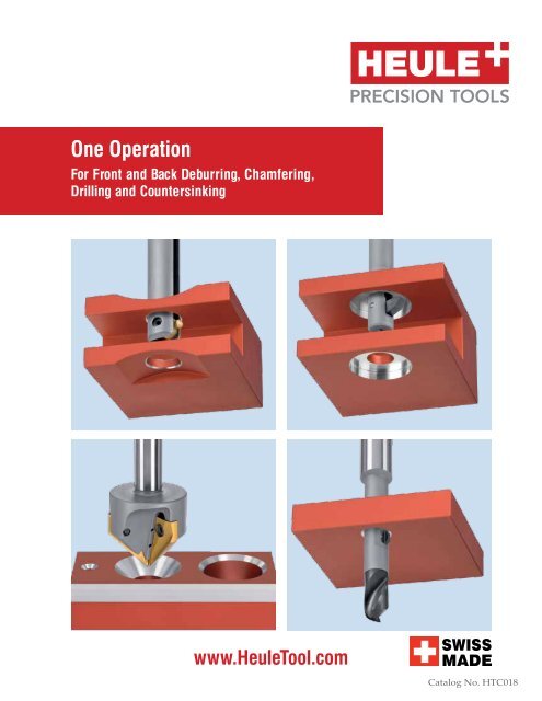
One Operation For Front and Back Deburring, Chamfering, Drilling and Countersinking www.HeuleTool.com Catalog No. HTC018
- Page 2 and 3: The Innovator and Quality Leader in
- Page 4 and 5: Series Table of Contents Catalog HT
- Page 6 and 7: Series Product Application Guide Ca
- Page 8 and 9: Series Case Study - Small Hole Oper
- Page 10 and 11: Series Case Study - Elliptical Debu
- Page 12 and 13: Series Case Study - Automotive Cata
- Page 14 and 15: Series Case Study - Automotive Cata
- Page 16 and 17: Series Case Study - Aerospace Catal
- Page 18 and 19: Series Case Study - Fluid Power Cat
- Page 20 and 21: Series Case Study - Industrial Cata
- Page 22 and 23: Series Catalog HTC019No. HTC14 www.
- Page 24 and 25: COFA Series Introduction Catalog HT
- Page 26 and 27: COFA Series Series 2 Deburring Tool
- Page 28 and 29: COFA Series Series Series 32 Deburr
- Page 30 and 31: COFA Series Series 4 Deburring Tool
- Page 32 and 33: COFA Series Series 5 Deburring Tool
- Page 34 and 35: COFA Series Series 6 Deburring Tool
- Page 36 and 37: COFA Series Series 8 Deburring Tool
- Page 38 and 39: COFA Series Series 12 Deburring Too
- Page 40 and 41: COFA Catalog HTC019No. HTC14 Series
- Page 42 and 43: COFA Series Series 12OS Deburring T
- Page 44 and 45: COFA Series Series CAS Cassette Deb
- Page 46 and 47: COFA Series Programming Information
- Page 48 and 49: COFA Series Changing Blades Catalog
- Page 50 and 51: COFA Series Changing Blades Catalog
One Operation<br />
For Front and Back Deburring, Chamfering,<br />
Drilling and Countersinking<br />
www.HeuleTool.com<br />
<strong>Catalog</strong> No. HTC018
The Innovator and Quality Leader<br />
in the Cutting Tool Industry since 1961
Innovative Tools with<br />
Timesaving Results<br />
Founded in 1961 by Heinrich Heule in the Rhine Valley of<br />
eastern Switzerland, <strong>HEULE</strong> continues to be a world leader<br />
in manufacturing of chamfering and deburring tools. After<br />
serving the European community for over 25 years, <strong>HEULE</strong><br />
expanded to the United States. Heule Tool Corporation has<br />
been providing high quality chamfering and deburring tools<br />
Innovative Tools with<br />
to the North American market since 1988.<br />
Timesaving Results<br />
<strong>HEULE</strong> is Founded committed in 1961 by Heinrich to the Heule values in the Rhine of quality, Valley of precision<br />
western Switzerland, <strong>HEULE</strong> continues to be a world leader in<br />
and service. Competent service, fast delivery times and<br />
manufacturing of chamfering and deburring tools. After serving<br />
customized<br />
the European<br />
solutions<br />
community<br />
are<br />
for<br />
the<br />
over<br />
highest<br />
25 years, <strong>HEULE</strong><br />
priorities.<br />
expanded<br />
From all<br />
ranks, <strong>HEULE</strong>’s to the United committed States. Heule Tool and Corporation motivated has been expert providing staff<br />
high quality chamfering and deburring tools to the North<br />
carry out their work with reliability and professionalism.<br />
American market since 1988.<br />
Customer’s worldwide attest to the high quality standard<br />
<strong>HEULE</strong> provides <strong>HEULE</strong> is committed and continually to the values improves of quality, precision,and through innovative<br />
service. Competent service, fast delivery times, and customized<br />
ideas and sophisticated technology.<br />
solutions are the highest priorities. From all ranks, <strong>HEULE</strong>’s<br />
committed and motivated expert staff carry out their work with<br />
reliability and professionalism. Customer’s worldwide attest<br />
to the high quality standard <strong>HEULE</strong> provides and continually<br />
improves through innovative ideas and sophisticated technology.<br />
MICROSNAP<br />
• State of the art and Eco friendly factory<br />
• Family owned and operated<br />
• Guaranteed customer satisfaction<br />
• Customized design and built tooling<br />
Table of Contents<br />
3 Case Study<br />
4 Introduction<br />
5-6 MICROSNAp Series 2<br />
7-8 MICROSNAp Series 3<br />
9-10 MICROSNAp Series 4<br />
11 Technical Instructions<br />
ONEOPERATION<br />
HeuleTool.com (513) 860-9900<br />
HeuleTool.com (513) 860-9900<br />
Heule Tool Corporation<br />
4722 A Interstate Drive | Cincinnati, Ohio 45246<br />
12 Technical Information<br />
13 Programming Information<br />
14 Technical Information
Series<br />
Table of Contents<br />
<strong>Catalog</strong> HTC019No. HTC14<br />
Product Application Guide......................................................Pgs 05-07<br />
Case Studies & Best Practices.................................................Pgs 08-22<br />
COFA – Elliptical Deburring Tool.........................................Pgs 23-54<br />
Series 2.................................................................................Pgs 26-27<br />
Series 3.................................................................................Pgs 28-29<br />
Series 4................................................................................. Pgs 30-31<br />
Series 5.................................................................................Pgs 32-33<br />
Series 6................................................................................ Pgs 34-35<br />
Series 8................................................................................ Pgs 36-37<br />
Series 12.............................................................................. Pgs 38-39<br />
Series 12OS......................................................................... Pgs 40-43<br />
Cassette............................................................................... Pgs 44-45<br />
Programming Information............................................. Pgs 46-47<br />
Changing Blades............................................................... Pgs 48-51<br />
Troubleshooting........................................................................ Pg 52<br />
Blade Options............................................................................ Pg 53<br />
COFA-C – New Generation Deburring Tool......................Pgs 55-72<br />
Series C6.............................................................................. Pgs 58-59<br />
Series C8.............................................................................. Pgs 60-61<br />
Series C12............................................................................ Pgs 62-63<br />
Cassette................................................................................Pgs 64-65<br />
Programming Information............................................. Pgs 66-67<br />
Changing Blades................................................................Pgs 68-71<br />
Troubleshooting........................................................................ Pg 72<br />
SNAP – Universal Chamfering Tool...................................Pgs 73-108<br />
MICRO SNAP – Micro Chamfering Tool.......Pgs 73-86<br />
Series 2..................................................................................Pgs 76-77<br />
Series 3..................................................................................Pgs 78-79<br />
Series 4................................................................................. Pgs 80-81<br />
Changing Blades........................................................................Pg 82<br />
Technical Information..............................................................Pg 83<br />
Programming Information.............................................. Pgs 84-85<br />
SNAP – Universal Chamfering Tool........................Pgs 87-108<br />
Series 5................................................................................. Pgs 90-91<br />
Series 8..................................................................................Pgs 92-93<br />
Series 12............................................................................... Pgs 94-95<br />
Series 20............................................................................... Pgs 96-97<br />
Snap 5 Cassette................................................................... Pgs 98-99<br />
Snap 35 Cassette.............................................................Pgs 100-101<br />
Series 5 Tapped Holes............................................................ Pg 102<br />
Blade Options..................................................................Pgs 103-104<br />
Technical Information............................................................Pg 105<br />
Programming Information...........................................Pgs 106-107<br />
Troubleshooting...................................................................... Pg 108<br />
VEX-S – Combination Drill/Chamfer..............................Pgs 109-122<br />
Series 1xd..........................................................................Pgs 112-113<br />
Series 2xd.........................................................................Pgs 114-115<br />
Programming Information...........................................Pgs 116-117<br />
Spare Parts................................................................................Pg 118<br />
Change Drill.............................................................................Pg 119<br />
Troubleshooting.............................................................Pgs 120-121<br />
VEX-P – Combination Drill/Chamfer............................. Pgs 123-130<br />
Series C..................................................................................... Pg 126<br />
Series D..................................................................................... Pg 127<br />
Technical Information........................................................... Pg 128<br />
Programming Information....................................................Pg 129<br />
Change Drill.............................................................................Pg 130<br />
COMBI – Combination Drill/Chamfer............................ Pgs 131-146<br />
Series Y, Z Drill/Chamfer......................................................Pg 134<br />
Series 0 Drill/Chamfer........................................................... Pg 135<br />
Series 1 Drill/Chamfer............................................................ Pg 136<br />
Series 2 Drill/Chamfer........................................................... Pg 137<br />
Series Y, Z Drill/Chamfer/Countersink............................. Pg 138<br />
Series 0 Drill/Chamfer/Countersink................................... Pg 139<br />
Series 1 Drill/Chamfer/Countersink................................... Pg 140<br />
Series 2 Drill/Chamfer/Countersink................................... Pg 141<br />
Programming Information.......................................... Pgs 142-144<br />
Spare Parts................................................................................Pg 145<br />
DEFA – Precision Chamfering............................................ Pgs 147-172<br />
Series 02-06................................................................... Pgs 150-151<br />
Series 07-09................................................................... Pgs 152-153<br />
Series 10-11...................................................................Pgs 154-155<br />
Series 12-13...................................................................Pgs 156-157<br />
Series 14-15...................................................................Pgs 158-159<br />
Series 16-17................................................................... Pgs 160-161<br />
Series 18-19................................................................... Pgs 162-163<br />
Series 22-24............................................................................... Pg 164<br />
Series 26-28............................................................................... Pg 165<br />
Series 30-32.............................................................................. Pg 166<br />
Blade Options........................................................................... Pg 167<br />
Setting ØD2 Dimension........................................................ Pg 168<br />
Programming Information............................................Pgs 169-170<br />
Technical Information....................................................Pgs 171-172<br />
GH-K – Chatter Free Countersinking.................................Pgs 173-178<br />
Ø25 Tool....................................................................................Pg 176<br />
Ø45 Tool....................................................................................Pg 177<br />
Programming and Changing Blades..................................Pg 178<br />
BSF – Back Counterboring and Spotfacing.......................Pgs 179-214<br />
Series A.....................................................................................Pg 181<br />
Series B...........................................................................Pgs 182-183<br />
Series C......................................................................... Pgs 184-185<br />
Series D......................................................................... Pgs 186-188<br />
Series E...........................................................................Pgs 189-193<br />
Series F.......................................................................... Pgs 194-199<br />
Series G.........................................................................Pgs 200-209<br />
Spare Parts.......................................................................Pgs 210-212<br />
Technical Information............................................................Pg 213<br />
Blade Dimensions....................................................................Pg 214<br />
Frequently Asked Questions................................................Pg 215<br />
Programming Informaiton...........................................Pgs 216-217<br />
Blade Change............................................................................Pg 218<br />
Troubleshooting.......................................................................Pg 219<br />
SOLO – Automatic Spotfacing..............................................Pgs 221-230<br />
SOLO 1900 Programming.....................................................Pg 226<br />
SOLO 2 Programming............................................................Pg 227<br />
Technical Information.................................................. Pgs 228-229<br />
GH-Z/E – Automatic Counterboring.................................. Pgs 231-235<br />
Programming Information...........................................Pgs 234-235<br />
APPENDIX – Reference Materials.....................................Pgs 236-243<br />
Application Data Sheets................................................Pgs 237-240<br />
Materials Reference Chart.....................................................Pg 241<br />
Metric to Inch Conversion Chart.........................................Pg 242<br />
Tool Recommendations........................................ Pg 243<br />
4<br />
513.860.9900 www.heuletool.com
Series<br />
Product Application Guide<br />
<strong>Catalog</strong> No. HTC019 HTC014<br />
COFA<br />
Universal Deburring Tool<br />
The COFA tool removes burrs on the front and back of a drilled<br />
through-hole on even and uneven surfaces in a single cycle.<br />
• Radial edge breaks on flat or uneven surfaces.<br />
• Deburr through holes on irregular surfaces up to 30°.<br />
• Typical edge break range .005-.015”.<br />
• Used on all materials; aluminum to nickel alloy.<br />
• Available in sizes 2mm (.080”) and up.<br />
Pages 23-54<br />
COFA-C<br />
The New Generation Deburring Tool<br />
The COFA-C tool is a new innovation of our proven COFA product.<br />
Like its predecessor, COFA-C will efficiently deburr bore edges in<br />
one single pass, but with added features to encompass a broader<br />
range of applications.<br />
• Designed for added durability.<br />
• Suitable for threaded bores and larger edge breaks.<br />
• Shorter working length for a more stable tool.<br />
• Newly-designed blade holder for better guidance<br />
and longer spring life.<br />
Pages 55-72<br />
SNAP<br />
Simple Front/Back Chamfering Tool<br />
The SNAP tool is easy to use and offers quick blade change,<br />
which makes it practical for any manufacturing environment.<br />
• Creates standard 90° controlled chamfers.<br />
• Most economical and fastest front and back<br />
chamfer tool.<br />
• Absolutely safe for reamed and finished holes.<br />
• Cutting blade options offer controlled<br />
chamfer sizes: .010”, .020”, .030” or .040” x 45°.<br />
• Used on all materials under 30Rc.<br />
• Available in sizes 2mm (.080”) and up.<br />
Pages 55-90<br />
513-860-9900 www.heuletool.com 5
Series<br />
Product Application Guide<br />
<strong>Catalog</strong> HTC019No. HTC14<br />
VEX-S<br />
Combination Front/Back Chamfering and Drilling<br />
The VEX-S tool combines a replaceable solid carbide high performance<br />
twist drill with Heule`s patented SNAP chamfering system to make<br />
drilling and front and back chamfering in a single operation possible.<br />
• Standard stock tooling for 1x and 2x diameter depth.<br />
• Replaceable drill tip can be reground and recoated.<br />
• Used on common steel and non-ferrous applications.<br />
• Available in sizes 5-12.7mm. Pages 91-104<br />
VEX-P<br />
Combination of Drilling and Front/Back Chamfering<br />
The VEX-P tool combines a replaceable solid carbide high<br />
performance drill tip with <strong>HEULE</strong>’s patented SNAP chamfering<br />
system to enable drilling and front and back chamfering in one<br />
operation.<br />
• VEX drill geometry for better chip control<br />
• Quick and easy drill tip and chamfer blade replacement<br />
• No presetting between drill changes<br />
• Sizes 11.0-17.0mm (.433-.669”) available from stock<br />
• Bore depths up to 1.5 times diameter<br />
COMBI<br />
Combination Chamfering and Drilling<br />
The COMBI tool combines front and back chamfering and drilling<br />
to save time, money, and space on your machining center.<br />
• Stock 1x diameter tooling accepts standard spade drills.<br />
• Custom made tooling for boring, drilling, and countersinking<br />
with chamfering.<br />
• Ideal for automotive applications: e.g. wheel and disc brake<br />
manufacturers.<br />
• Available in sizes 9.5-35mm.<br />
DEFA<br />
Precision Front/Back Chamfering<br />
Double bladed DEFA chamfering tools create<br />
pre-adjusted front and back chamfers in a single operation<br />
without stopping or reversing the spindle.<br />
• Sliding-surface blade geometry prevents damage to<br />
finished hole surfaces.<br />
• Precise, adjustable chamfer sizes up to .050” x 45°.<br />
• Used on all materials, cast steel to nickel base materials.<br />
• Available in sizes 4-44.5mm.<br />
Pages 105-112<br />
Pages 113-128<br />
Pages 129-154<br />
6<br />
513.860.9900 www.heuletool.com
Series<br />
Product Application Guide<br />
<strong>Catalog</strong> No. HTC019 HTC014<br />
GH-K<br />
Precision Chatter-Free Countersinks<br />
The GH-K countersink blades are precision ground as a matched set<br />
to achieve unmatched countersink finishes.<br />
• Totally chatter-free.<br />
• Suitable for chamfer milling.<br />
• Used in manual and CNC applications.<br />
• Used on cast iron, aluminum and other long chipping material.<br />
• Available with a 3-45mm countersink range, 60°, 82°, 90° and<br />
100°<br />
BSF<br />
Back Spot Facing Tool<br />
The BSF backspotfacing tool is an easy to use tool concept that<br />
allows back spotfacing or counterboring in one operation without<br />
turning the workpiece<br />
• Large ratio automatic back counterboring and spotfacing tool<br />
• Usable for counter bores up to 2.3xd<br />
• Very simple to use<br />
• Especially usable for CNC machining<br />
• Through coolant minimum 280 psi<br />
• Available for bore sizes 6.5-20.5mm<br />
Pages 155-160<br />
Pages 161-196<br />
SOLO<br />
Automatic Front/Back Counterboring<br />
The SOLO tool is an easy to program tool for automatic back<br />
spotfacing through holes with positive control in a single opertion.<br />
• No anti-rotation device or machine adaptations needed.<br />
• No change of spindle rotation, no contact mechanism<br />
and no coolant pressure required for blade activation.<br />
• Counterbore sizes up to 2x hole diameter -1mm.<br />
• Available for bore sizes 8-30mm<br />
Pages 197-206<br />
GH-Z/E<br />
Automatic Front/Back Spotfacing Systems<br />
The GH-Z/E is a twin bladed front and back counterboring tool<br />
that makes back spotfaces, large countersinks, and precision forms.<br />
• Used in large bore applications and difficult to<br />
cut situations.<br />
• No chip interference with blade activation.<br />
• Reversing the spindle activates the blades,<br />
blades do not flip out.<br />
• Counterbore sizes up to 2x hole diameter -1mm.<br />
Pages 207-211<br />
513-860-9900 www.heuletool.com 7
Series<br />
Case Study - Small Hole Operation<br />
<strong>Catalog</strong> HTC019No. HTC14<br />
MICROCOFA<br />
Small Precision Front/<br />
Back Deburr Solutions<br />
for Small Hole Operations<br />
TOOL<br />
COFA3-3.6-S with blade C3-M-0011-A (back cutting only)<br />
Theoretical deburring Ø4.2<br />
PRODUCTION<br />
2400 per day with 24 holes in tube<br />
MACHINE<br />
CNC machining center<br />
MATERIAL<br />
Similar to St52 steel with approximately 700N/mm2<br />
Study Details<br />
The MICRO SERIES, for COFA 2 and 3, is for all purpose<br />
deburring of through holes 2mm-4.1mm (.079”-.161”),<br />
front and back, in a single pass. Heule’s MICRO COFA<br />
deburring tool is the answer for today’s manufacturers<br />
requiring more simple and flexible solutions without<br />
sacrificing quality or tool life.<br />
MICRO COFA is a very simple tool for deburring through<br />
holes on even or uneven parts from the top and bottom<br />
without reversing the spindle, dwelling, or indexing the<br />
part. The MICRO COFA tool offers a simple to use, high<br />
quality deburring tool with Carbide inserts coated with<br />
TiAIN to meet today’s manufacturing needs.<br />
HOLE SIZE<br />
Cross hole Ø3.6 with main Hole Ø12.0 which are 90° to each other.<br />
Need to be back deburred (unevenness on a Ø4.2mm deburring<br />
diameter to Ø12.0 main hole = 0.37mm or 10.24°)<br />
BLADE<br />
Blade life is over 4500 holes<br />
PARAMETER<br />
s= 2500 RPM, f=0.05mm/rev.<br />
S-Spring, flood coolant<br />
PRODUCT<br />
SECTION<br />
PG.<br />
23<br />
The COFA Family<br />
2mm - 41mm (.079” - 1.614”)<br />
8<br />
513.860.9900 www.heuletool.com
Series<br />
Case Study - Automotive<br />
<strong>Catalog</strong> No. HTC019 HTC014<br />
COFA<br />
Consistent Deburring<br />
Through Holes on<br />
Even & Uneven<br />
Surfaces in Any Material<br />
BEFORE<br />
AFTER<br />
Study Details<br />
TOOL<br />
COFA Tool<br />
PRODUCTION<br />
1,400 parts / day (2 holes per part)<br />
MACHINE<br />
CNC Machining Center<br />
MATERIAL<br />
Low Carbon Steel<br />
HOLE SIZE<br />
Ø.630mm hole requiring even edge<br />
break of .005-.015” on all 4 surfaces<br />
DETAILS<br />
Tool COFA12-599-Z<br />
Speed 1180 RPM<br />
Feed 0.3mm/rev<br />
Life 4000-5000 parts<br />
CYCLE TIME<br />
12 seconds per part<br />
REPLACING<br />
Hand benching<br />
Tired of inconsistent hole chamfers? Our COFA tools<br />
produce consistent edge breaks EVERY time, front<br />
and back, in one pass. No adjusting screws or setting<br />
requirements are necessary. Each tool is sized for<br />
your application and material. Operators might be<br />
skeptical... until they see it run.<br />
“After seeing parts made by the<br />
<strong>HEULE</strong> tool, our customer will<br />
no longer accept hand benching<br />
of their parts.”<br />
The COFA tool removes the burrs from elliptical bores<br />
created when drilling into round parts, contoured<br />
surfaces, or angled faces. Cuts a tapered radius<br />
rather than an angled chamfer.<br />
PRODUCT<br />
SECTION<br />
PG.<br />
23<br />
513-860-9900 www.heuletool.com 9
Series<br />
Case Study - Elliptical Deburring<br />
<strong>Catalog</strong> HTC019No. HTC14<br />
COFA-C<br />
Elliptical Deburring<br />
Tool with Exchangable<br />
Blade Options<br />
Blade Working Principle<br />
TOOL<br />
COFA C6-6.09-S<br />
C6-M-0021-T<br />
PRODUCTION<br />
3500 Per Day<br />
3 Cells<br />
1 hole per part<br />
MACHINE<br />
Vertical machining center<br />
with robot load<br />
MATERIAL<br />
Cast steel<br />
PROCESSING<br />
Tool: COFA C6-6.0-S<br />
Speed: 1100 RPM<br />
Feed: 140 mm/m (5.5 IPM)<br />
Life: 3500 holes<br />
Cycle Time: 3.62 seconds<br />
per hole<br />
Study Details<br />
1 Tool Body<br />
2 Spring<br />
3 Blade Holder<br />
4 Blade<br />
5 Cutting edge forward<br />
6 Cutting edge backward<br />
Typical Applications<br />
COFA has been specifically designed for front and back<br />
deburring on even and uneven bore edges, in one operation. It<br />
radially removes the burrs from the bore edges. Independent of<br />
the Z-position of the work piece, the deburring capacity of the<br />
tool does not vary.<br />
The tool concept is suitable for both soft and difficult to machine<br />
materials. This is done without the need for preadjustments.<br />
The blades are made out of coated carbide and guarantee<br />
a long tool life. They are interchangeable according to the<br />
required deburring capacity. Typical applications are forks,<br />
yokes, common rails, castings, tubes with cross bores and other<br />
work pieces with cross bores in main bores.<br />
REMARKS<br />
Customer had trouble leaving the drill cap in the 23mm bore. They<br />
used a bore scope to 100% inspect. Now this is not needed.<br />
The COFA system guarantees a consistent, radially<br />
shaped deburring of even and uneven bore edges.<br />
10<br />
513.860.9900 www.heuletool.com
Series<br />
Case Study - Small Hole Operation<br />
<strong>Catalog</strong> No. HTC019 HTC014<br />
MICROSNAP<br />
Small Precision Front/Back<br />
Chamfer Solutions for Small<br />
Hole Operations<br />
Study Details<br />
TOOL<br />
MICRO SNAP front & back chamfer<br />
tool<br />
PRODUCTION<br />
450 pc/wk 6x holes/part<br />
MACHINE<br />
CNC Vert. machining centers<br />
MATERIAL<br />
Case harden steel<br />
HOLE SIZE<br />
Ø2.4+/-.05 26.5mm deep breaking<br />
into Ø10mm diameter cross hole<br />
DETAILS<br />
Tool MICRO Spec Ø2.25<br />
Speed 3300 RPM<br />
Feed .045mm/rev<br />
Blade GH-Q-M-42671<br />
Ø2.8mm x 60° Carbide TiAIN back<br />
only cutting 60°<br />
OUTCOME<br />
Consistent deburring improving part<br />
quality<br />
The Micro tools expands Heule Tool’s ability to offer<br />
quality, automated deburring tools with multiple<br />
carbide blade choices for front and back chamfers<br />
in almost any material. Our standard inserts are<br />
ground to exact chamfer sizes which will not<br />
damage or mark the through hole.<br />
“The Micro Series tools are<br />
REALLY working great...”<br />
This automotive supplier is deburring several small<br />
cross holes in a critical component. The holes<br />
required only a break edge, but due to the difficulty<br />
to machine material and cross hole situation,<br />
carbide “back cutting only” blades were used.<br />
Using our Patented MICRO<br />
DF-Geometry allows our<br />
tools to cut consistent<br />
chamfers in INCONEL,<br />
TITANIUM and other<br />
Super Alloy steels.<br />
PRODUCT<br />
SECTION<br />
PG.<br />
55<br />
513-860-9900 www.heuletool.com 11
Series<br />
Case Study - Automotive<br />
<strong>Catalog</strong> HTC019No. HTC14<br />
SNAP<br />
Fast and Accurate SNAP<br />
Tooling is Able to Produce<br />
Large Chamfers with No<br />
Secondary Burr Issues<br />
BEFORE<br />
AFTER<br />
Study Details<br />
TOOL<br />
SNAP front & back chamfer tool<br />
PRODUCTION<br />
8,000 parts / week<br />
MACHINE<br />
CNC Vert. machining centers<br />
MATERIAL<br />
Low carbon steel<br />
HOLE SIZE<br />
Ø13.0mm hole requires 0.5mm<br />
max chamfer 2x places with no<br />
secondary burr<br />
DETAILS<br />
Tool SNAP12-512<br />
Speed 280 SFM<br />
Feed 0.2mm/rev<br />
Life 10,500+<br />
REPLACING<br />
Secondary operation<br />
OUTCOME<br />
Consistent chamfer to specification<br />
PRODUCT<br />
SECTION<br />
PG.<br />
69<br />
Our standard chamfering system takes the guess<br />
work out of producing front and back chamfers. The<br />
insert geometry is ground to the exact chamfer sizes<br />
and capable of running 2-3x faster than competitive<br />
tooling. This low carbon steel automotive component<br />
was drilled and reamed leaving behind heavy<br />
burrs causing problems with automated assembly<br />
machines and eventually transmission quality.<br />
“We got the consistency we<br />
needed to keep our production<br />
going, AND saw a $45,000/yr<br />
saving in time and labor.”<br />
The heavy burr causing the problem was removed<br />
using a SNAP tool with front and back cutting blade.<br />
With clean and chamfered edge breaks, assembly<br />
problems were eliminated.<br />
Each Standard SNAP<br />
tool comes with the<br />
choice of 4 chamfer sizes:<br />
0.25, 0.5, 0.75 and 1.0mm.<br />
Can be used with<br />
threaded / tapped holes.<br />
12<br />
513.860.9900 www.heuletool.com
Series<br />
Case Study - Flange Hole Drilling<br />
<strong>Catalog</strong> No. HTC019 HTC014<br />
VEX-S<br />
Drill & Front/Back Chamfer<br />
in ONE STEP. Rotors, Hubs,<br />
Axle Flanges...<br />
Study Details<br />
TOOL<br />
VEX-S<br />
PRODUCTION<br />
1,000,000 / yr<br />
MACHINE<br />
Emag multi spindle machine<br />
MATERIAL<br />
Steel 52, 7mm thickness<br />
HOLE SIZE<br />
Ø8.0mm; hole requires chamfer size<br />
9.5mm x 90° front & back<br />
DETAILS<br />
Tool Multiple<br />
Speed 3700 RPM<br />
Feed 0.14mm/rev (0.006 IPR)<br />
Life Drill life 4-5,000 holes<br />
REPLACING<br />
Tool Drill & 2 countersinking<br />
operations.<br />
Cycle time is always a premium and so is quality.<br />
Each time tooling can be combined into one<br />
operation, while at the same time producing a better<br />
product, everyone wins. The VEX tool combines<br />
drilling and front/back chamfering into a single tool.<br />
Save setup time, cycle time and tool space.<br />
“We saved over $60,000 just by<br />
eliminating a second machine<br />
operation.”<br />
The VEX-S drill geometry limits chip wrapping issues<br />
or interference with any mechanical operations of<br />
the deburr operations. The single bladed front/back<br />
SNAP chamfer blade is easy to use and offers quick<br />
change features so the tools never leave the machine.<br />
Most common application is deburring bolt holes in<br />
flanges. From 5mm to 12.7mm.<br />
PRODUCT<br />
SECTION<br />
PG.<br />
91<br />
513-860-9900 www.heuletool.com 13
Series<br />
Case Study - Automotive<br />
<strong>Catalog</strong> HTC019No. HTC14<br />
VEX-P<br />
Combination of Drilling<br />
and Front/Back<br />
Chamfering in<br />
One Operation.<br />
Study Details<br />
TOOL<br />
VEX-P<br />
PRODUCTION<br />
30,000 parts per month<br />
MACHINE<br />
Vertical CNC<br />
MATERIAL<br />
1050 Steel<br />
HOLE SIZE<br />
Ø13.0mm (.512”) drilled front<br />
and back chamfered in one single<br />
operation<br />
DETAILS<br />
Tool:<br />
Speed: VEX-P SNAP12 drill combi<br />
Feed: 3720 RPM 500 SFM<br />
VEX: 0.25 mm/rev (.0101” IPR)<br />
Life: SNAP: 0.20 mm/rev (.008” IPR)<br />
VEX: 4,500 holes/<br />
SNAP: 13,500 holes<br />
The VEX-P tool combines a replaceable solid<br />
carbide high performance drill tip with <strong>HEULE</strong>’s<br />
patented SNAP chamfering system to enable<br />
drilling and front and back chamfering in one<br />
operation.<br />
“The Vex-P combination tool<br />
replaced two tools and cut<br />
our cycle time in half for that<br />
operation....”<br />
For bores from diameters 11.00 mm to 17.0 mm<br />
(0.433 - 0.669”) and bore depths up to 1.5 times<br />
diameter.<br />
REPLACING<br />
Solid carbide and secondary operation<br />
PRODUCT<br />
SECTION<br />
PG.<br />
105<br />
14<br />
513.860.9900 www.heuletool.com
Series<br />
Case Study - Wheel Rim Drill<br />
<strong>Catalog</strong> No. HTC019 HTC014<br />
COMBI<br />
The Fastest Multi-Task<br />
Wheel Rim Tool on<br />
The Market<br />
Study Details<br />
TOOL<br />
COMBI multi-task drill back chamfer<br />
tool with coolant through.<br />
PRODUCTION<br />
250,000 wheels / month<br />
MACHINE<br />
Horizontal Machining Centers<br />
MATERIAL<br />
Cast Aluminum 7%<br />
HOLE SIZE<br />
Ø15.7, 19.0 & 21.6mm; hole requires<br />
front countersink and counter bore<br />
Ø32.0mm & back chamfer.<br />
DETAILS<br />
Tool Multiple<br />
Speed 6500-10,500 (2,336 SFM)<br />
Feed<br />
Life<br />
0.3-0.4mm/rev (0.015 IPR)<br />
All drills, countersinks and<br />
deburr blades are changed<br />
every 8 days.<br />
REPLACING<br />
Circle Interpolation and wheel flip<br />
operations tool.<br />
Our aluminum and steel wheel Multi-Tasking tools for<br />
the lug nut drill chamfer operations lead the industry<br />
in performance and efficiency. Capable of increasing<br />
part production with high performance, accurate<br />
drills, combined with <strong>HEULE</strong>’s patented back chamfer<br />
SNAP system.<br />
“The cycle time savings are<br />
huge... in one day alone we get<br />
157 more wheels out of the cell.”<br />
All robot wheel cells that require back chamfers now<br />
use <strong>HEULE</strong> tools. Some tool holders have run over<br />
ONE MILLION holes. Also using COFA tooling for<br />
deburring uneven stem holes.<br />
PRODUCT<br />
SECTION<br />
PG.<br />
113<br />
513-860-9900 www.heuletool.com 15
Series<br />
Case Study - Aerospace<br />
<strong>Catalog</strong> HTC019No. HTC14<br />
DEFA<br />
Accurate Tooling for Front/<br />
Back Chamfers in Difficult<br />
Materials<br />
Adjustable<br />
Blades<br />
Sliding<br />
Edge<br />
DEFA<br />
Tool<br />
Tool<br />
Path<br />
45°<br />
Definition<br />
Surface<br />
DEFA Blade<br />
Radial Blade Force<br />
Chamfer Diameter "D"<br />
Chamfer Angle<br />
Study Details<br />
TOOL<br />
Twin bladed DEFA tools with coated<br />
carbide blades<br />
PRODUCTION<br />
2 parts / wk (360 holes / part)<br />
MACHINE<br />
NC Horizontal<br />
MATERIAL<br />
Inconel 718<br />
HOLE SIZE<br />
Ø.345 and Ø.401 requiring front/back<br />
break edge 0.005-0.015”.<br />
DETAILS<br />
Tool DEFA11-34-339 &<br />
DEFA13-30-390<br />
Speed 60 SFM<br />
Feed 0.002 IPR<br />
Life Blade life: 800-2000 holes<br />
Chamfer 0.010”x90°<br />
REPLACING<br />
Manual bench operation, minimizing<br />
a potential ergonomic risk.<br />
Flat Cutting Edge<br />
Tested and approved by the major jet engine and<br />
aircraft component suppliers, the DEFA tooling will<br />
not leave any witness mark inside your finish holes,<br />
and produces accurate front & back chamfer break<br />
edges in Titanium, Inconel and other Nickel alloys.<br />
“...the Heule tooling took a 2<br />
1/2 hour manual operation and<br />
reduced it to only 10 minutes.”<br />
The form blade set can be adjusted radially to exact<br />
required chamfer size; in most cases within<br />
+/- 0.003. The cutting blades are held inside the<br />
tool with <strong>HEULE</strong>’s patented pin drive system. One<br />
blade cannot collapse without the other.<br />
PRODUCT<br />
SECTION<br />
PG.<br />
129<br />
16<br />
513.860.9900 www.heuletool.com
Series<br />
Case Study - Automotive<br />
<strong>Catalog</strong> No. HTC019 HTC014<br />
BSF<br />
Large Ratio Automatic<br />
Back Counterboring &<br />
Spotfacing Tool<br />
Blade Working Principle<br />
Study Details<br />
TOOL<br />
BSF 12.6 - 22.0 with working<br />
length 80 mm<br />
Blade: carbide DLC coated<br />
INDUSTRY<br />
Automotive<br />
WORK PIECE<br />
Cylinder head<br />
MATERIAL<br />
Cast aluminum<br />
APPLICATION<br />
Bore: Ø12.6 mm<br />
Spot face: Ø22.0 mm<br />
Back Spotfacing up to 2.3 x Bore Diameter<br />
The simple BSF tool concept allows back spotfacing or<br />
back counterboring in one operation without turning the<br />
workpiece, activated with through coolant.<br />
The BSF spotfaces up to 2.3 times the bore diameter.<br />
Our standard range starts with holes as small as 6.5mm<br />
to 20.5 mm and designed to cut all materials.<br />
PROCESSING<br />
Spindle speed: 2000 rev/min<br />
Feed: 0.05 mm/rev<br />
Cooling: internal coolant<br />
Coolant Pressure: 500 PSI<br />
Shaving: short chips<br />
REMARKS<br />
Due to the interrupted cut, the tool was out of the recommended<br />
parameters, and was of concern. The customer took the risk and<br />
it was worth it. The interupted cut caused chatter which was<br />
corrected with higher spindle speed.<br />
PRODUCT<br />
SECTION<br />
PG.<br />
161<br />
Clean Surface Finish<br />
513-860-9900 www.heuletool.com 17
Series<br />
Case Study - Fluid Power<br />
<strong>Catalog</strong> HTC019No. HTC14<br />
SOLO<br />
High Production Automated<br />
Back Spotfacing Tool<br />
Study Details<br />
TOOL<br />
Automated Back Spotfacing<br />
PRODUCTION<br />
4 or 8 bolt holes on the flanges<br />
of 316 stainless valves<br />
MACHINE<br />
Mazak Ultra 650 horizontal<br />
machining center<br />
MATERIAL<br />
Stainless Steel<br />
HOLE SIZE<br />
Ø34.8mm counter bore;<br />
Ø19.05mm through hole<br />
DETAILS<br />
Tool SOLO 2<br />
Speed 613 RPM<br />
Feed<br />
Life<br />
.002 IPR<br />
420 holes<br />
(indexable carbide)<br />
REPLACING<br />
Competitors hinge-type tool<br />
The switch in tooling significantly reduced cycle time.<br />
Machining time on valve bottoms, which included<br />
boring the hole to size, drilling and back spotfacing,<br />
dropped from 39 minutes to 15. While this is running<br />
at the low end of the recommended speed and feed<br />
range, it was a vast improvement in productivity.<br />
“So far we’ve run 420 counter<br />
bores, up from 32 on the old<br />
tool and we’ve only indexed<br />
the two-sided inserts once.”<br />
Custom back spotfacing tools that can produce<br />
front and back spotfaces and counterbores allow<br />
for reduced cycle times and extended tool life.<br />
Capable of cutting nickel based alloys.<br />
PRODUCT<br />
SECTION<br />
PG.<br />
197<br />
Rene 88<br />
18<br />
513.860.9900 www.heuletool.com
Series<br />
Case Study - Power Generation<br />
<strong>Catalog</strong> No. HTC019 HTC014<br />
GH-Z<br />
Large Automated Back<br />
Counter Bore Solutions<br />
for the Power Generation<br />
Industry & Large Part<br />
Manufacturers<br />
Study Details<br />
TOOL<br />
Single Blade Automated Back Counter<br />
bore with Indexible Cutting Inserts<br />
PRODUCTION<br />
1-2 hubs / week (198 counter bores/<br />
part)<br />
MACHINE<br />
Large vertical boring mill<br />
MATERIAL<br />
Cast Iron<br />
HOLE SIZE<br />
Ø39.0mm hole requires an Ø75.0mm<br />
back counter bore up to 15.0mm<br />
deep. (interrupted cut from casting<br />
variance)<br />
DETAILS<br />
Tool GH-E 50<br />
Speed<br />
Feed<br />
Life<br />
390 RPM<br />
0.1mm/rev (0.004 IPR) <strong>Full</strong><br />
diameter counter bore<br />
depth... up to 15mm deep<br />
(indexable) 1 part<br />
REPLACING<br />
Competitors flip-out style tooling<br />
<strong>HEULE</strong> has been manufacturing the strongest and<br />
most reliable automated back counter bore tools<br />
for over 30 years. Some tools reach over several<br />
feet and can weigh over 50 lbs.<br />
Large interrupted cuts created tool breakage<br />
problems for this customer slowing machine<br />
time. By purchasing a <strong>HEULE</strong> automatic back<br />
counter bore system the problem was solved.<br />
“...increased production and<br />
shortened a 15 hour operation<br />
to only 2.5 hours.”<br />
This customer is currently running on two large<br />
boring mills with coolant through the spindle<br />
capability. Other common applications include;<br />
landing gear, crane and hoist components as well<br />
as hydro and other turbine manufacturers.<br />
PRODUCT<br />
SECTION<br />
PG.<br />
207<br />
513-860-9900 www.heuletool.com 19
Series<br />
Case Study - Industrial<br />
<strong>Catalog</strong> HTC019No. HTC14<br />
SPECIALS<br />
Custom Multi-Tasking<br />
Easy and Cost Effective<br />
Study Details<br />
TOOL<br />
Precision Mico Adjusting Boring Unit<br />
with SNAP chamfer cassette<br />
PRODUCTION<br />
300,000 / yr<br />
MACHINE<br />
Horizontal Machining Centers<br />
MATERIAL<br />
Cast Aluminum<br />
HOLE SIZE<br />
Ø76.2mm and Ø73.0mm; requires<br />
front/back chamfer of 74.1mm x 60°<br />
DETAILS<br />
Tool COMBI multi-task bore and<br />
front/back chamfer with std.<br />
deburr cassette chamfer<br />
blade 60 degree carbide<br />
diamond film cutting blade.<br />
Speed 1070 SFM (1,400 RPM)<br />
Feed 6 IPM<br />
Life 10,000+<br />
REPLACING<br />
Cycle time reduced 20% (1.5 min)<br />
Our SNAP & COFA cassettes and custom-made<br />
tooling make ordinary boring operations into money<br />
making processes by saving space and time. Any<br />
large bore operation above 1” can utilize a <strong>HEULE</strong><br />
front & back chamfer cassette.<br />
“We saved approximately<br />
$150,000 a year by cutting over<br />
1 min./part out of production<br />
of 300,000 parts a year.”<br />
Challenge: The cast surface where the 76mm bore<br />
was produced could move in location as much as<br />
6mm. The spring loaded <strong>HEULE</strong> chamfer cartridge<br />
with special 60 degree cutting blades produced the<br />
same size chamfers front and back regardless of<br />
surface location.<br />
PRODUCT<br />
SECTION<br />
PG.<br />
CALL<br />
20<br />
513.860.9900 www.heuletool.com
Series<br />
Case Study - Industrial<br />
<strong>Catalog</strong> No. HTC019 HTC014<br />
SPECIALS<br />
Custom Multi-Tasking<br />
Easy and Cost Effective<br />
Study Details<br />
TOOL<br />
COMP V2 Tool<br />
PRODUCTION<br />
40,000 a month<br />
PART<br />
Housing with 4 hole bolt pattern<br />
MATERIAL<br />
Cast Aluminum<br />
HOLE SIZE<br />
Ø7.6mm<br />
COUNTERSINK<br />
0.30 ± 0.12mm x 72.5°± 2°<br />
Speed<br />
Feed<br />
500 RPM<br />
.007 IPR<br />
REPLACING<br />
Replaced solid carbide countersink<br />
which could not hold countersink<br />
tolerance due to 0.3 casting variation<br />
PRODUCT<br />
SECTION<br />
PG.<br />
CALL<br />
Meeting aerospace customers’ further need for accuracy<br />
and non-rotational end effectors that cannot mark<br />
super critical finishes, the COMP tool was born. The<br />
<strong>HEULE</strong> COMP highlights the true meaning of swiss<br />
engineering and innovation by meeting the challenges of<br />
manufacturing state of the art tooling that can hold up in<br />
high demand production facilities.<br />
“We’ve had the tool in production<br />
with no problems... our scrap rate<br />
went from approx. 400 pcs a month<br />
to less than one due to chamfer<br />
issues...”<br />
There are three different versions:<br />
V1: Allowed simple insertable inserts to front countersink<br />
or radius drill holes where the surface of the part varied<br />
V2: Allowed the cage to contact the part first avoiding<br />
chip interference. The double compression action allowed<br />
for drilling and countersinking with a carbide drill<br />
V3: Offers fine adjustment to the chamfer depth of .0008”<br />
(0.02MM), a longer drill depth of up to 3xd, and<br />
non-rotating end effector.<br />
513-860-9900 www.heuletool.com 21
Series<br />
<strong>Catalog</strong> HTC019No. HTC14<br />
www.HeuleTool.com<br />
For more case studies, testimonials,<br />
and videos<br />
We provide online tool selectors for the<br />
COFA, SNAP, DEFA and BSF product groups.<br />
Simply enter your application information and the correct tool will<br />
be provided complete with order number and sample drawing.<br />
We are also available on:<br />
22<br />
513.860.9900 www.heuletool.com
COFA<br />
Deburring Tool<br />
for Elliptical or<br />
Contoured Surfaces<br />
• Replaceable solid carbide coated blades<br />
• Blade coatings offer longer tool life and<br />
increased performance<br />
• Sizes 2-27mm (.079-1.063”) available<br />
from stock<br />
• Breakthrough technology provides<br />
consistent quality<br />
Cat. No. HTC019
COFA<br />
Series<br />
Introduction<br />
<strong>Catalog</strong> HTC019No. HTC14<br />
COFA COFA-C l SNAP l VEX-S l VEX-P l COMBI l DEFA l GH-K l BSF l SOLO l GH-Z/E<br />
The <strong>HEULE</strong> COFA deburring tool removes burrs from the front and back of a drilled<br />
through hole without stopping or reversing the spindle. Whether you are deburring a<br />
flat surface or an irregular surface, the edge break is always even and consistent.<br />
Deburr Elliptical Holes<br />
The COFA tool will deburr the contours of an elliptical hole<br />
when two holes intersect or a hole is not perpendicular to<br />
the surface. The COFA with a standard blade can be used<br />
when the larger intersecting hole is two or more times<br />
the smaller or for surfaces up to 15°. Deburr more extreme<br />
contours by using a 30° blade with extra clearance relief.<br />
Radiused Edge Breaks on Flat Parts<br />
Deburr the front and back of any through hole with a<br />
smooth tapered edge break to relieve stress points and<br />
sharp corners. Use the blade with 10° clearance relief for<br />
better tool life when deburring flat parts.<br />
Wide Range of Tools<br />
Our COFA tool is a proven winner for any deburring<br />
challenge, and now with the addition of the COFA-C New<br />
Generation line, your process capability and efficiency<br />
is even further expanded to include threaded holes and<br />
larger edge breaks (see the COFA-C section page 55 for<br />
more information).<br />
COFA tools are available from stock for immediate<br />
delivery in sizes 2mm-41mm (.079”-1.614”). The COFA<br />
Cassette is also in stock for deburring even larger holes<br />
quickly and efficiently.<br />
24<br />
513.860.9900 www.heuletool.com
COFA<br />
Series<br />
Introduction<br />
<strong>Catalog</strong> No. HTC019 HTC014<br />
How Does It Work?<br />
Controlled by a simple spring, the carbide cutting blade follows<br />
the contour of the hole’s surface removing all burrs while creating<br />
an even tapered corner break. The blade does not cut as it passes<br />
through the bore and will not damage the hole’s surface.<br />
The edge break begins only at the point where the blade makes<br />
contact with the material and then tapers the hole’s edge. This<br />
allows for faster feed rates since the tool slows itself down as it<br />
enters the through hole.<br />
The simple concept of the COFA tool has no adjusting screws or<br />
presetting requirements. Only a choice of common tool sizes and<br />
spring strengths for various materials and hole sizes.<br />
Typical Parts<br />
How to Order:<br />
Ordering is simple. The COFA tool provides different blade and spring options to create the most effective tool for any<br />
application depending on the hole geometry and type of material being machined.<br />
1. Choose the tool that best fits the hole diameter.<br />
2. Choose the blade that best fits the hole geometry.<br />
3. Choose the spring that best fits the material.<br />
Example:<br />
Tool<br />
Series<br />
COFA4 b – 4.0 - W<br />
Blade<br />
Option<br />
Min. Hole<br />
Dia. Ød<br />
Spring<br />
Option<br />
COFA COFA-C l SNAP l VEX-S l VEX-P l COMBI l DEFA l GH-K l BSF l SOLO l GH-Z/E<br />
513-860-9900 www.heuletool.com<br />
25
COFA<br />
Series<br />
Series<br />
2<br />
Deburring Tools –<br />
For holes 2.0 - 3.1mm .079 - .122”<br />
<strong>Catalog</strong> HTC019No. HTC14<br />
COFA COFA-C l SNAP l VEX-S l VEX-P l COMBI l DEFA l GH-K l BSF l SOLO l GH-Z/E<br />
Ød<br />
Min. Hole<br />
mm inches<br />
Ød1<br />
0.38 (.015”)<br />
4.5 (.177”)<br />
3 (.118”)<br />
COFA Deburring Series 2<br />
Ød1<br />
Tool Diameter<br />
+0/- .03<br />
mm inches<br />
H = 15.3 (.602”)<br />
ØD¹<br />
Approx. Cutting<br />
Diameter<br />
mm inches<br />
2.0 .079 1.95 .077 2.2 .087<br />
2.1 .083 2.05 .081 2.3 .090<br />
2.2 .087 2.15 .085 2.4 .094<br />
2.3 .091 2.25 .089 2.5 .098<br />
2.4 .094 2.35 .092 2.6 .102<br />
2.5 .099 2.45 .096 2.7 .106<br />
2.6 .102 2.55 .100 2.8 .110<br />
2.7 .106 2.65 .104 2.9 .114<br />
2.8 .110 2.75 .108 3.0 .118<br />
2.9 .114 2.85 .112 3.1 .122<br />
3.0 .118 2.95 .116 3.2 .126<br />
3.1 .122 3.05 .120 3.3 .130<br />
60 (2.362”)<br />
Front and Back<br />
Order Number<br />
COFA2-2.0-<br />
COFA2-2.1-<br />
COFA2-2.2-<br />
COFA2-2.3-<br />
COFA2-2.4-<br />
COFA2-2.5-<br />
COFA2-2.6-<br />
COFA2-2.7-<br />
COFA2-2.8-<br />
COFA2-2.9-<br />
COFA2-3.0-<br />
COFA2-3.1-<br />
37 (1.457”)<br />
Ø8mm<br />
Complete Tool with Blade<br />
Back Only<br />
Order Number<br />
COFA2b-2.0-<br />
COFA2b-2.1-<br />
COFA2b-2.2-<br />
COFA2b-2.3-<br />
COFA2b-2.4-<br />
COFA2b-2.5-<br />
COFA2b-2.6-<br />
COFA2b-2.7-<br />
COFA2b-2.8-<br />
COFA2b-2.9-<br />
COFA2b-3.0-<br />
COFA2b-3.1-<br />
Spring Choice: W, H, S, Z<br />
¹ The deburring result varies depending on material, cutting data and application. The indicated dimension is the theoretically<br />
possible maximum. The spring has to be selected accordingly.<br />
BLADE<br />
OPTIONS<br />
PG.<br />
53<br />
Easy to change<br />
Blade and pin<br />
(tab that snaps off)<br />
SPARE<br />
PARTS<br />
PG.<br />
27<br />
26<br />
513.860.9900 www.heuletool.com
COFA<br />
Series<br />
Series<br />
2<br />
Spare Parts<br />
<strong>Catalog</strong> No. HTC019 HTC014<br />
Spare Parts – COFA 2<br />
Spring Options:<br />
The cutting force of the COFA tool is controlled by a flat spring<br />
Choose the proper spring for the material being machined.<br />
Spring Order Typical Materials<br />
Code Number Large or Heavy Burrs may require a stronger spring<br />
Harder Softer<br />
W C2-E-0013 Aluminum, Brass, Magnesium<br />
H C2-E-0014 Grey Cast Iron, Nodular Iron<br />
S C2-E-0015 Carbon Steel, Free Machining Steel<br />
Z* C2-E-0016 Nickel, Titanium, Stainless<br />
* Not recommended with COFA2-2.0 tool.<br />
How to Order:<br />
The COFA tool provides different blade and spring options to create the most effective tool for any application depending<br />
on the hole geometry and type of material being machined.<br />
1. Choose the tool that best fits the hole diameter.<br />
2. Choose the blade that best fits the hole geometry.<br />
3. Choose the spring that best fits the material.<br />
Example:<br />
Tool<br />
Series<br />
Blade<br />
Option<br />
6<br />
1 2 3 4 5 6 7<br />
Retainer Pin Assembly Pin Split Pin Blade Spring Set Screw Wrench Fixture<br />
GH-H-S-1017 C2-V-0001 C2-E-0002 See Below See Below GH-H-S-0135 GH-H-S-2106 C3-V-0002<br />
COFA2 b – 2.0 - W<br />
Min. Hole<br />
Dia. Ød<br />
Spring<br />
Option<br />
Blade Options:<br />
Blades are available from stock as front and<br />
back cutting (fab) or back cutting only (bco).<br />
Blade<br />
Code<br />
b<br />
y<br />
yb<br />
Blade Type Geo. Series 2<br />
TiALN 20°<br />
Standard<br />
TiALN 10°<br />
PROGRAMMING<br />
7<br />
fab<br />
bco<br />
fab<br />
bco<br />
PG.<br />
46-47<br />
Optional<br />
C2-M-0006-A<br />
C2-M-0016-A<br />
C2-M-0007-A<br />
C2-M-0017-A<br />
COFA COFA-C l SNAP l VEX-S l VEX-P l COMBI l DEFA l GH-K l BSF l SOLO l GH-Z/E<br />
CHANGE BLADES<br />
PG.<br />
48-51<br />
513-860-9900 www.heuletool.com<br />
27
COFA<br />
Series<br />
Series<br />
Series<br />
32<br />
Deburring Tools –<br />
For holes 3.0 - 4.1mm .118 - .161”<br />
<strong>Catalog</strong> HTC019No. HTC14<br />
COFA COFA-C l SNAP l VEX-S l VEX-P l COMBI l DEFA l GH-K l BSF l SOLO l GH-Z/E<br />
COFA Deburring Series 3<br />
Ød<br />
Min. Hole<br />
mm inches<br />
Ød1<br />
Ød1<br />
.53 (.021”)<br />
6 (.236”)<br />
4 (.157”)<br />
Tool Diameter<br />
+0/- .03<br />
mm inches<br />
ØD¹<br />
3.0 .118 2.95 .116 3.3 .130<br />
3.1 .122 3.05 .120 3.4 .134<br />
3.2 .126 3.15 .124 3.5 .138<br />
3.3 .130 3.25 .128 3.6 .142<br />
3.4 .134 3.35 .132 3.7 .146<br />
3.5 .138 3.45 .136 3.8 .150<br />
3.6 .142 3.55 .140 3.9 .154<br />
3.7 .146 3.65 .144 4.0 .157<br />
3.8 .150 3.75 .148 4.1 .161<br />
3.9 .154 3.85 .152 4.2 .165<br />
4.0 .158 3.95 .156 4.3 .169<br />
4.1 .161 4.05 .159 4.4 .173<br />
H = 20.8 (.819”)<br />
Approx. Cutting<br />
Diameter<br />
mm inches<br />
66 (2.598”)<br />
Front and Back<br />
Order Number<br />
COFA3-3.0-<br />
COFA3-3.1-<br />
COFA3-3.2-<br />
COFA3-3.3-<br />
COFA3-3.4-<br />
COFA3-3.5-<br />
COFA3-3.6-<br />
COFA3-3.7-<br />
COFA3-3.8-<br />
COFA3-3.9-<br />
COFA3-4.0-<br />
COFA3-4.1-<br />
36.5 (1.437”)<br />
Complete Tool with Blade<br />
Ø8mm<br />
Back Only<br />
Order Number<br />
COFA3b-3.0-<br />
COFA3b-3.1-<br />
COFA3b-3.2-<br />
COFA3b-3.3-<br />
COFA3b-3.4-<br />
COFA3b-3.5-<br />
COFA3b-3.6-<br />
COFA3b-3.7-<br />
COFA3b-3.8-<br />
COFA3b-3.9-<br />
COFA3b-4.0-<br />
COFA3b-4.1-<br />
Spring Choice: W, H, S, Z<br />
¹ The deburring result varies depending on material, cutting data and application. The indicated dimension is the theoretically<br />
possible maximum. The spring has to be selected accordingly.<br />
BLADE<br />
OPTIONS<br />
PG.<br />
53<br />
Easy to change<br />
Blade and pin<br />
(tab that snaps off)<br />
SPARE<br />
PARTS<br />
PG.<br />
29<br />
28<br />
513.860.9900 www.heuletool.com
COFA<br />
Series<br />
Series<br />
3<br />
Spare Parts<br />
<strong>Catalog</strong> No. HTC019 HTC014<br />
Spare Parts – COFA 3<br />
Spring Options:<br />
The cutting force of the COFA tool is controlled by a flat spring<br />
Choose the proper spring for the material being machined.<br />
Spring Order Typical Materials<br />
Code Number Large or Heavy Burrs may require a stronger spring<br />
Harder Softer<br />
W C3-E-0013 Aluminum, Brass, Magnesium<br />
H C3-E-0014 Grey Cast Iron, Nodular Iron<br />
S C3-E-0015 Carbon Steel, Free Machining Steel<br />
Z C3-E-0016 Nickel, Titanium, Stainless<br />
How to Order:<br />
The COFA tool provides different blade and spring options to create the most effective tool for any application depending<br />
on the hole geometry and type of material being machined.<br />
1. Choose the tool that best fits the hole diameter.<br />
2. Choose the blade that best fits the hole geometry.<br />
3. Choose the spring that best fits the material.<br />
Example:<br />
Tool<br />
Series<br />
Blade<br />
Option<br />
6<br />
1 2 3 4 5 6 7<br />
Retainer Pin Assembly Pin Split Pin Blade Spring Set Screw Wrench Fixture<br />
GH-H-S-1017 C3-V-0001 C3-E-0002 See Below See Below GH-H-S-0135 GH-H-S-2106 C3-V-0002<br />
COFA3 b – 3.0 - W<br />
Min. Hole<br />
Dia. Ød<br />
Spring<br />
Option<br />
Blade Options:<br />
Blades are available from stock as front and<br />
back cutting (fab) or back cutting only (bco).<br />
Blade<br />
Code<br />
b<br />
y<br />
yb<br />
Blade Type Geo. Series 3<br />
TiALN 20°<br />
Standard<br />
TiALN 10°<br />
PROGRAMMING<br />
7<br />
fab<br />
bco<br />
fab<br />
bco<br />
PG.<br />
46-47<br />
Optional<br />
C3-M-0006-A<br />
C3-M-0016-A<br />
C3-M-0007-A<br />
C3-M-0017-A<br />
COFA COFA-C l SNAP l VEX-S l VEX-P l COMBI l DEFA l GH-K l BSF l SOLO l GH-Z/E<br />
CHANGE BLADES<br />
PG.<br />
48-51<br />
513-860-9900 www.heuletool.com<br />
29
COFA<br />
Series<br />
Series<br />
4<br />
Deburring Tools –<br />
For holes 4.0 - 4.9mm .157 - .193”<br />
<strong>Catalog</strong> HTC019No. HTC14<br />
COFA COFA-C l SNAP l VEX-S l VEX-P l COMBI l DEFA l GH-K l BSF l SOLO l GH-Z/E<br />
COFA Deburring Series 4<br />
Ød Ød1 ØD¹ Complete Tool with Blade<br />
Min. Hole Tool Dia. Approx. Cutting Dia. Front and Back Back Only<br />
mm inches mm inches mm inches Order Number Order Number<br />
4.0 .157 3.9 .154 4.5 .177 COFA4-4.0- COFA4b-4.0-<br />
4.1 .161 4.0 .157 4.6 .181 COFA4-4.1- COFA4b-4.1-<br />
4.2 .165 4.1 .161 4.7 .185 COFA4-4.2- COFA4b-4.2-<br />
4.3 .169 4.2 .165 4.8 .189 COFA4-4.3- COFA4b-4.3-<br />
4.4 .173 4.3 .169 4.9 .193 COFA4-4.4- COFA4b-4.4-<br />
4.5 .177 4.4 .173 5.0 .197 COFA4-4.5- COFA4b-4.5-<br />
4.6 .181 4.5 .177 5.1 .201 COFA4-4.6- COFA4b-4.6-<br />
4.7 .185 4.6 .181 5.2 .205 COFA4-4.7- COFA4b-4.7-<br />
4.8 .189 4.7 .185 5.3 .209 COFA4-4.8- COFA4b-4.8-<br />
4.9 .193 4.8 .189 5.4 .213 COFA4-4.9- COFA4b-4.9-<br />
Spring Choice: W, H, S, Z, Z1<br />
¹ The deburring result varies depending on material, cutting data and application. The indicated dimension is<br />
the theoretically possible maximum. The spring has to be selected accordingly.<br />
BLADE<br />
OPTIONS<br />
PG.<br />
53<br />
SPARE<br />
PARTS<br />
PG.<br />
31<br />
30<br />
513.860.9900 www.heuletool.com
COFA<br />
Series<br />
Series<br />
4<br />
Spare Parts<br />
<strong>Catalog</strong> No. HTC019 HTC014<br />
Spare Parts – COFA 4<br />
1 2 3 4 5 6<br />
Retainer Pin Assembly Pin Split Pin Blade Spring Fixture<br />
GH-H-S-0902 GH-C-V-0206 GH-C-E-0819 See Below See Below GH-C-V-0541<br />
Spring Options:<br />
The cutting force of the COFA tool is controlled by a flat spring<br />
Choose the proper spring for the material being machined.<br />
Spring Order Typical Materials<br />
Code Number Large or Heavy Burrs may require a stronger spring<br />
W GH-C-E-0342 Aluminum, Brass, Magnesium<br />
Harder Softer<br />
H GH-C-E-0343 Grey Cast Iron, Nodular Iron<br />
S GH-C-E-0344 Carbon Steel, Free Machining Steel<br />
Z GH-C-E-0345 Long Chipping Steel, Stainless<br />
Z1 GH-C-E-0346 Titanium, Hardened Steel, Nickel Alloy<br />
How to Order:<br />
The COFA tool provides different blade and spring options to create the most effective tool for any application depending<br />
on the hole geometry and type of material being machined.<br />
1. Choose the tool that best fits the hole diameter.<br />
2. Choose the blade that best fits the hole geometry.<br />
3. Choose the spring that best fits the material.<br />
Example:<br />
Tool<br />
Series<br />
COFA4 b – 4.0 - Z1<br />
Blade<br />
Option<br />
Min. Hole<br />
Dia. Ød<br />
Spring<br />
Option<br />
Blade Options:<br />
Blades are available from stock as front and<br />
back cutting (fab) or back cutting only (bco).<br />
Blade<br />
Code<br />
b<br />
y<br />
yb<br />
x<br />
xb<br />
Blade Type Geo. Series 4<br />
TiN 20°<br />
Standard<br />
TiCN 10°<br />
Flat Surfaces<br />
TiN 30°<br />
Uneven Spec<br />
PROGRAMMING<br />
6<br />
fab<br />
bco<br />
fab<br />
bco<br />
fab<br />
bco<br />
PG.<br />
46-47<br />
Optional<br />
GH-C-M-0504<br />
GH-C-M-0914<br />
GH-C-M-0744<br />
GH-C-M-0854<br />
GH-C-M-0148<br />
GH-C-M-0182<br />
COFA COFA-C l SNAP l VEX-S l VEX-P l COMBI l DEFA l GH-K l BSF l SOLO l GH-Z/E<br />
CHANGE BLADES<br />
PG.<br />
48-51<br />
513-860-9900 www.heuletool.com<br />
31
COFA<br />
Series<br />
Series<br />
5<br />
Deburring Tools –<br />
For holes 5.0 - 5.9mm .197 - .232”<br />
<strong>Catalog</strong> HTC019No. HTC14<br />
COFA COFA-C l SNAP l VEX-S l VEX-P l COMBI l DEFA l GH-K l BSF l SOLO l GH-Z/E<br />
COFA Deburring Series 5<br />
Ød Ød1 ØD¹ Complete Tool with Blade<br />
Min. Hole Tool Dia. Approx. Cutting Dia. Front and Back Back Only<br />
mm inches mm inches mm inches Order Number Order Number<br />
5.0 .197 4.9 .193 5.7 .224 COFA5-5.0- COFA5b-5.0-<br />
5.1 .201 5.0 .197 5.8 .228 COFA5-5.1- COFA5b-5.1-<br />
5.2 .205 5.1 .201 5.9 .232 COFA5-5.2- COFA5b-5.2-<br />
5.3 .209 5.2 .205 6.0 .236 COFA5-5.3- COFA5b-5.3-<br />
5.4 .213 5.3 .209 6.1 .240 COFA5-5.4- COFA5b-5.4-<br />
5.5 .217 5.4 .213 6.2 .244 COFA5-5.5- COFA5b-5.5-<br />
5.6 .220 5.5 .217 6.3 .248 COFA5-5.6- COFA5b-5.6-<br />
5.7 .224 5.6 .220 6.4 .252 COFA5-5.7- COFA5b-5.7-<br />
5.8 .228 5.7 .224 6.5 .256 COFA5-5.8- COFA5b-5.8-<br />
5.9 .232 5.8 .228 6.6 .260 COFA5-5.9- COFA5b-5.9-<br />
Spring Choice: W, H, S, Z, Z1<br />
¹ The deburring result varies depending on material, cutting data and application. The indicated dimension is<br />
the theoretically possible maximum. The spring has to be selected accordingly.<br />
BLADE<br />
OPTIONS<br />
PG.<br />
53<br />
SPARE<br />
PARTS<br />
PG.<br />
33<br />
32<br />
513.860.9900 www.heuletool.com
COFA<br />
Series<br />
Series<br />
5<br />
Spare Parts<br />
<strong>Catalog</strong> No. HTC019 HTC014<br />
Spare Parts – COFA 5<br />
1 2 3 4 5 6<br />
Retainer Pin Assembly Pin Split Pin Blade Spring Fixture<br />
GH-H-S-0902 GH-C-V-0211 GH-C-E-0820 See Below See Below GH-C-V-0541<br />
Spring Options:<br />
The cutting force of the COFA tool is controlled by a flat spring<br />
Choose the proper spring for the material being machined.<br />
Spring Order Typical Materials<br />
Code Number Large or Heavy Burrs may require a stronger spring<br />
W GH-C-E-0352 Aluminum, Brass, Magnesium<br />
How to Order:<br />
The COFA tool provides different blade and spring options to create the most effective tool for any application depending<br />
on the hole geometry and type of material being machined.<br />
1. Choose the tool that best fits the hole diameter.<br />
2. Choose the blade that best fits the hole geometry.<br />
3. Choose the spring that best fits the material.<br />
Example:<br />
Tool<br />
Series<br />
Harder Softer<br />
H GH-C-E-0353 Grey Cast Iron, Nodular Iron<br />
S GH-C-E-0354 Carbon Steel, Free Machining Steel<br />
Z GH-C-E-0355 Long Chipping Steel, Stainless<br />
Z1 GH-C-E-0356 Titanium, Hardened Steel, Nickel Alloy<br />
COFA5 b – 5.0 - Z1<br />
Blade<br />
Option<br />
Min. Hole<br />
Dia. Ød<br />
Spring<br />
Option<br />
Blade Options:<br />
Blades are available from stock as front and<br />
back cutting (fab) or back cutting only (bco).<br />
Blade<br />
Code<br />
b<br />
y<br />
yb<br />
x<br />
xb<br />
Blade Type Geo. Series 5<br />
TiN 20°<br />
Standard<br />
TiCN 10°<br />
Flat Surfaces<br />
TiN 30°<br />
Uneven Spec<br />
PROGRAMMING<br />
6<br />
fab<br />
bco<br />
fab<br />
bco<br />
fab<br />
bco<br />
PG.<br />
46-47<br />
Optional<br />
GH-C-M-0505<br />
GH-C-M-0915<br />
GH-C-M-0745<br />
GH-C-M-0855<br />
GH-C-M-0150<br />
GH-C-M-0184<br />
COFA COFA-C l SNAP l VEX-S l VEX-P l COMBI l DEFA l GH-K l BSF l SOLO l GH-Z/E<br />
CHANGE BLADES<br />
PG.<br />
48-51<br />
513-860-9900 www.heuletool.com<br />
33
COFA<br />
Series<br />
Series<br />
6<br />
Deburring Tools –<br />
For holes 6.0 - 8.0mm .236 - .315”<br />
<strong>Catalog</strong> HTC019No. HTC14<br />
COFA COFA-C l SNAP l VEX-S l VEX-P l COMBI l DEFA l GH-K l BSF l SOLO l GH-Z/E<br />
COFA Deburring Series 6<br />
Ød Ød1 ØD¹ Complete Tool with Blade<br />
Min. Hole Tool Dia. Approx. Cutting Dia. Front and Back Back Only<br />
mm inches mm inches mm inches Order Number Order Number<br />
6.0 .236 5.8 .228 6.7 .264 COFA6-236- COFA6b-236-<br />
6.2 .244 6.0 .236 6.9 .272 COFA6-244- COFA6b-244-<br />
6.4 .252 6.2 .244 7.1 .279 COFA6-252- COFA6b-252-<br />
6.6 .260 6.4 .252 7.3 .287 COFA6-260- COFA6b-260-<br />
6.8 .268 6.6 .260 7.5 .295 COFA6-268- COFA6b-268-<br />
7.0 .276 6.8 .268 7.7 .303 COFA6-276- COFA6b-276-<br />
7.2 .284 7.0 .276 7.9 .311 COFA6-284- COFA6b-284-<br />
7.4 .291 7.2 .283 8.1 .319 COFA6-291- COFA6b-291-<br />
7.6 .299 7.4 .291 8.3 .327 COFA6-299- COFA6b-299-<br />
7.8 .307 7.6 .299 8.5 .335 COFA6-307- COFA6b-307-<br />
8.0 .315 7.8 .307 8.7 .342 COFA6-315- COFA6b-315-<br />
Spring Choice: W, H, S, Z, Z1, Z2, Z3<br />
¹ The deburring result varies depending on material, cutting data and application. The indicated dimension is<br />
the theoretically possible maximum. The spring has to be selected accordingly.<br />
BLADE<br />
OPTIONS<br />
PG.<br />
53<br />
SPARE<br />
PARTS<br />
PG.<br />
35<br />
34<br />
513.860.9900 www.heuletool.com
COFA<br />
Series<br />
Series<br />
6<br />
Spare Parts<br />
<strong>Catalog</strong> No. HTC019 HTC014<br />
1<br />
Spare Parts – COFA 6<br />
2 3<br />
1 2 3 4 5 6<br />
Retainer Block Assembly Pin Screw Roll Pin Blade Spring<br />
GH-C-E-0812 GH-C-V-0126 GH-H-S-0803 GH-C-E-0811 See Below See Below<br />
Spring Options:<br />
The cutting force of the COFA tool is controlled by a flat spring<br />
Choose the proper spring for the material being machined.<br />
Spring Order Typical Materials<br />
Code Number Large or Heavy Burrs may require a stronger spring<br />
W GH-C-E-0321 Aluminum, Brass, Magnesium<br />
How to Order:<br />
The COFA tool provides different blade and spring options to create the most effective tool for any application depending<br />
on the hole geometry and type of material being machined.<br />
1. Choose the tool that best fits the hole diameter.<br />
2. Choose the blade that best fits the hole geometry.<br />
3. Choose the spring that best fits the material.<br />
Example:<br />
Tool<br />
Series<br />
Harder Softer<br />
H GH-C-E-0322 Grey Cast Iron, Nodular Iron<br />
S GH-C-E-0323 Carbon Steel, Free Machining Steel<br />
Z GH-C-E-0324 Long Chipping Steel, Stainless<br />
Z1 GH-C-E-0325 Titanium, Hardened Steel, Nickel Alloy<br />
Z2 GH-C-E-0326 Nickel Alloy, etc<br />
Z3 GH-C-E-0327 Nickel Alloy, etc<br />
COFA6 b – 236 - Z1<br />
Blade<br />
Option<br />
Min. Hole<br />
Dia. Ød<br />
(Inches)<br />
Spring<br />
Option<br />
6<br />
4<br />
5<br />
Blade Options:<br />
Blades are available from stock as front and back<br />
cutting (fab) or back cutting only (bco).<br />
Blade<br />
Code<br />
b<br />
y<br />
yb<br />
x<br />
xb<br />
Blade Type Geo. Series 6<br />
TiN 20°<br />
Standard<br />
TiCN 10°<br />
Flat Surfaces<br />
TiN 30°<br />
Uneven Spec<br />
PROGRAMMING<br />
fab<br />
bco<br />
fab<br />
bco<br />
fab<br />
bco<br />
PG.<br />
46-47<br />
GH-C-M-0002<br />
GH-C-M-0012<br />
GH-C-M-0442<br />
GH-C-M-0452<br />
GH-C-M-0142<br />
GH-C-M-0143<br />
COFA COFA-C l SNAP l VEX-S l VEX-P l COMBI l DEFA l GH-K l BSF l SOLO l GH-Z/E<br />
CHANGE BLADES<br />
PG.<br />
48-51<br />
513-860-9900 www.heuletool.com<br />
35
COFA<br />
Series<br />
Series<br />
8<br />
Deburring Tools –<br />
For holes 8.0 - 12.2mm .315 - .480”<br />
<strong>Catalog</strong> HTC019No. HTC14<br />
COFA COFA-C l SNAP l VEX-S l VEX-P l COMBI l DEFA l GH-K l BSF l SOLO l GH-Z/E<br />
COFA Deburring Series 8<br />
Ød Ød1 ØD¹ Complete Tool with Blade<br />
Min. Hole Tool Dia. Approx. Cutting Dia. Front and Back Back Only<br />
mm inches mm inches mm inches Order Number Order Number<br />
8.0 .315 7.8 .307 9.0 .354 COFA8-315-<br />
8.2 .323 8.0 .315 9.2 .362 COFA8-323-<br />
8.4 .331 8.2 .323 9.4 .370 COFA8-331-<br />
8.6 .339 8.4 .331 9.6 .378 COFA8-339-<br />
8.8 .346 8.6 .339 9.8 .386 COFA8-346-<br />
9.0 .354 8.8 .346 10.0 .394 COFA8-354-<br />
9.2 .362 9.0 .354 10.2 .402 COFA8-362-<br />
9.4 .370 9.2 .362 10.4 .409 COFA8-370-<br />
9.6 .378 9.4 .370 10.6 .417 COFA8-378-<br />
9.8 .386 9.6 .378 10.8 .425 COFA8-386-<br />
10.0 .394 9.8 .386 11.0 .433 COFA8-394-<br />
10.2 .402 10.0 .394 11.2 .441 COFA8-402-<br />
10.4 .409 10.2 .402 11.4 .449 COFA8-409-<br />
10.6 .417 10.4 .409 11.6 .457 COFA8-417-<br />
10.8 .425 10.6 .417 11.8 .465 COFA8-425-<br />
11.0 .433 10.8 .425 12.0 .473 COFA8-433-<br />
11.2 .441 11.0 .433 12.2 .480 COFA8-441-<br />
11.4 .449 11.2 .441 12.4 .488 COFA8-449-<br />
11.6 .457 11.4 .449 12.6 .496 COFA8-457-<br />
11.8 .465 11.6 .457 12.8 .504 COFA8-465-<br />
12.0 .473 11.8 .465 13.0 .512 COFA8-473-<br />
12.2 .480 12.0 .473 13.2 .520 COFA8-480-<br />
COFA8b-315-<br />
COFA8b-323-<br />
COFA8b-331-<br />
COFA8b-339-<br />
COFA8b-346-<br />
COFA8b-354-<br />
COFA8b-362-<br />
COFA8b-370-<br />
COFA8b-378-<br />
COFA8b-386-<br />
COFA8b-394-<br />
COFA8b-402-<br />
COFA8b-409-<br />
COFA8b-417-<br />
COFA8b-425-<br />
COFA8b-433-<br />
COFA8b-441-<br />
COFA8b-449-<br />
COFA8b-457-<br />
COFA8b-465-<br />
COFA8b-473-<br />
COFA8b-480-<br />
Spring Choice: W, H, S, Z, Z1, Z2, Z3<br />
¹ The deburring result varies depending on material, cutting data and application. The indicated dimension is the<br />
theoretically possible maximum. The spring has to be selected accordingly.<br />
BLADE<br />
OPTIONS<br />
PG.<br />
53<br />
SPARE<br />
PARTS<br />
PG.<br />
37<br />
36<br />
513.860.9900 www.heuletool.com
COFA<br />
Series<br />
Series<br />
8<br />
Spare Parts<br />
<strong>Catalog</strong> No. HTC019 HTC014<br />
Spare Parts – COFA 8<br />
1<br />
2 3<br />
1 2 3 4 5 6<br />
Retainer Block Assembly Pin Screw Roll Pin Blade Spring<br />
GH-C-E-0808 GH-C-V-0111 GH-H-S-0517 GH-C-E-0810 See Below See Below<br />
Spring Options:<br />
The cutting force of the COFA tool is controlled by a flat spring<br />
Choose the proper spring for the material being machined.<br />
Spring Order Typical Materials<br />
Code Number Large or Heavy Burrs may require a stronger spring<br />
W GH-C-E-0331 Aluminum, Brass, Magnesium<br />
How to Order:<br />
The COFA tool provides different blade and spring options to create the most effective tool for any application depending<br />
on the hole geometry and type of material being machined.<br />
1. Choose the tool that best fits the hole diameter.<br />
2. Choose the blade that best fits the hole geometry.<br />
3. Choose the spring that best fits the material.<br />
Example:<br />
Tool<br />
Series<br />
Harder Softer<br />
H GH-C-E-0332 Grey Cast Iron, Nodular Iron<br />
S GH-C-E-0333 Carbon Steel, Free Machining Steel<br />
Z GH-C-E-0334 Long Chipping Steel, Stainless<br />
Z1 GH-C-E-0335 Titanium, Hardened Steel, Nickel Alloy<br />
Z2 GH-C-E-0336 Nickel Alloy, etc<br />
Z3 GH-C-E-0337 Nickel Alloy, etc<br />
COFA8 b – 315 - Z1<br />
Blade<br />
Option<br />
Min. Hole<br />
Dia. Ød<br />
(Inches)<br />
Spring<br />
Option<br />
6<br />
4<br />
5<br />
Blade Options:<br />
Blades are available from stock as front and back<br />
cutting (fab) or back cutting only (bco).<br />
Blade<br />
Code<br />
b<br />
y<br />
yb<br />
x<br />
xb<br />
Blade Type Geo. Series 8<br />
TiN 20°<br />
Standard<br />
TiCN 10°<br />
Flat Surfaces<br />
TiN 30°<br />
Uneven Spec<br />
PROGRAMMING<br />
fab<br />
bco<br />
fab<br />
bco<br />
fab<br />
bco<br />
PG.<br />
46-47<br />
GH-C-M-0003<br />
GH-C-M-0013<br />
GH-C-M-0443<br />
GH-C-M-0453<br />
GH-C-M-0133<br />
GH-C-M-0131<br />
COFA COFA-C l SNAP l VEX-S l VEX-P l COMBI l DEFA l GH-K l BSF l SOLO l GH-Z/E<br />
CHANGE BLADES<br />
PG.<br />
48-51<br />
513-860-9900 www.heuletool.com<br />
37
COFA<br />
Series<br />
Series<br />
12<br />
Deburring Tools –<br />
For holes 12.4 - 20.0mm .488 - .788”<br />
<strong>Catalog</strong> HTC019No. HTC14<br />
COFA COFA-C l SNAP l VEX-S l VEX-P l COMBI l DEFA l GH-K l BSF l SOLO l GH-Z/E<br />
COFA Deburring Series 12<br />
Ød Ød1 ØD¹ Complete Tool with Blade<br />
Min. Hole Tool Dia. Approx. Cutting Dia. Front and Back Back Only<br />
mm inches mm inches mm inches Order Number Order Number<br />
12.4 .488 12.2 .480 13.8 .543 COFA12-488-<br />
12.8 .504 12.6 .496 14.2 .559 COFA12-504-<br />
13.2 .520 13.0 .512 14.6 .575 COFA12-520-<br />
13.6 .536 13.4 .528 15.0 .591 COFA12-536-<br />
14.0 .551 13.8 .543 15.4 .606 COFA12-551-<br />
14.4 .567 14.2 .559 15.8 .622 COFA12-567-<br />
14.8 .583 14.6 .575 16.2 .638 COFA12-583-<br />
15.2 .599 15.0 .591 16.6 .654 COFA12-599-<br />
15.6 .614 15.4 .606 17.0 .669 COFA12-614-<br />
16.0 .630 15.8 .622 17.4 .685 COFA12-630-<br />
16.4 .646 16.2 .638 17.8 .701 COFA12-646-<br />
16.8 .662 16.6 .654 18.2 .717 COFA12-662-<br />
17.2 .677 17.0 .669 18.6 .732 COFA12-677-<br />
17.6 .693 17.4 .685 19.0 .748 COFA12-693-<br />
18.0 .709 17.8 .701 19.4 .764 COFA12-709-<br />
18.4 .725 18.2 .717 19.8 .780 COFA12-725-<br />
18.8 .740 18.6 .732 20.2 .795 COFA12-740-<br />
19.2 .756 19.0 .748 20.6 .811 COFA12-756-<br />
19.6 .772 19.4 .764 21.0 .827 COFA12-772-<br />
20.0 .788 19.8 .780 21.4 .843 COFA12-788-<br />
COFA12b-488-<br />
COFA12b-504-<br />
COFA12b-520-<br />
COFA12b-536-<br />
COFA12b-551-<br />
COFA12b-567-<br />
COFA12b-583-<br />
COFA12b-599-<br />
COFA12b-614-<br />
COFA12b-630-<br />
COFA12b-646-<br />
COFA12b-662-<br />
COFA12b-677-<br />
COFA12b-693-<br />
COFA12b-709-<br />
COFA12b-725-<br />
COFA12b-740-<br />
COFA12b-756-<br />
COFA12b-772-<br />
COFA12b-788-<br />
Spring Choice: W, H, S, Z, Z1, Z2, Z3<br />
¹ The deburring result varies depending on material, cutting data and application. The indicated dimension is the<br />
theoretically possible maximum. The spring has to be selected accordingly.<br />
BLADE<br />
OPTIONS<br />
PG.<br />
53<br />
SPARE<br />
PARTS<br />
PG.<br />
39<br />
38<br />
513.860.9900 www.heuletool.com
COFA<br />
Series<br />
Series<br />
12<br />
Spare Parts<br />
<strong>Catalog</strong> No. HTC019 HTC014<br />
Spare Parts – COFA 12<br />
1<br />
2 3<br />
1 2 3 4 5 6<br />
Retainer Block Assembly Pin Screw Roll Pin Blade Spring<br />
GH-C-E-0800 GH-C-V-0100 GH-H-S-0530 GH-C-E-0801 See Below See Below<br />
Spring Options:<br />
The cutting force of the COFA tool is controlled by a flat spring<br />
Choose the proper spring for the material being machined.<br />
Spring Order Typical Materials<br />
Code Number Large or Heavy Burrs may require a stronger spring<br />
W GH-C-E-0361 Aluminum, Brass, Magnesium<br />
How to Order:<br />
The COFA tool provides different blade and spring options to create the most effective tool for any application depending<br />
on the hole geometry and type of material being machined.<br />
1. Choose the tool that best fits the hole diameter.<br />
2. Choose the blade that best fits the hole geometry.<br />
3. Choose the spring that best fits the material.<br />
Example:<br />
Tool<br />
Series<br />
Harder Softer<br />
H GH-C-E-0362 Grey Cast Iron, Nodular Iron<br />
S GH-C-E-0363 Carbon Steel, Free Machining Steel<br />
Z GH-C-E-0364 Long Chipping Steel, Stainless<br />
Z1 GH-C-E-0365 Titanium, Hardened Steel, Nickel Alloy<br />
Z2 GH-C-E-0366 Nickel Alloy, etc<br />
Z3 GH-C-E-0367 Nickel Alloy, etc<br />
COFA12 b – 488 - Z1<br />
Blade<br />
Option<br />
Min. Hole<br />
Dia. Ød<br />
(Inches)<br />
Spring<br />
Option<br />
6<br />
4<br />
5<br />
Blade Options:<br />
Blades are available from stock as front and back<br />
cutting (fab) or back cutting only (bco).<br />
Blade<br />
Code<br />
b<br />
y<br />
yb<br />
x<br />
xb<br />
Blade Type Geo. Series 12<br />
TiN 20°<br />
Standard<br />
TiCN 10°<br />
Flat Surfaces<br />
TiN 30°<br />
Uneven Spec<br />
PROGRAMMING<br />
fab<br />
bco<br />
fab<br />
bco<br />
fab<br />
bco<br />
PG.<br />
46-47<br />
GH-C-M-0007<br />
GH-C-M-0017<br />
GH-C-M-0447<br />
GH-C-M-0457<br />
GH-C-M-0105<br />
GH-C-M-0104<br />
COFA COFA-C l SNAP l VEX-S l VEX-P l COMBI l DEFA l GH-K l BSF l SOLO l GH-Z/E<br />
CHANGE BLADES<br />
PG.<br />
48-51<br />
513-860-9900 www.heuletool.com<br />
39
COFA<br />
<strong>Catalog</strong> HTC019No. HTC14<br />
Series<br />
Series<br />
12OS<br />
Deburring Tools –<br />
For holes 20.5 - 30.0mm .807 - 1.181”<br />
COFA COFA-C l SNAP l VEX-S l VEX-P l COMBI l DEFA l GH-K l BSF l SOLO l GH-Z/E<br />
COFA Deburring Series 12 OVERSIZE - METRIC<br />
Ød Ød1 ØD¹ Complete Tool with Blade<br />
Min. Hole Tool Dia. Approx. Cutting Dia. Front and Back Back Only<br />
mm inches mm inches mm inches Order Number Order Number<br />
20.5 .807 20.3 .799 21.8 .858 COFA12-20.5-<br />
20.8 .819 20.6 .811 22.2 .874 COFA12-20.8-<br />
21.0 .827 20.8 .819 22.4 .882 COFA12-21.0-<br />
21.2 .835 21.0 .827 22.6 .890 COFA12-21.2-<br />
21.5 .847 21.3 .838 23.0 .906 COFA12-21.5-<br />
22.0 .866 21.8 .858 23.4 .921 COFA12-22.0-<br />
22.5 .886 22.3 .878 23.9 .941 COFA12-22.5-<br />
22.8 .898 22.6 .890 24.2 .953 COFA12-22.8-<br />
23.0 .905 22.8 .898 24.4 .960 COFA12-23.0-<br />
23.2 .914 23.0 .906 24.6 .969 COFA12-23.2-<br />
23.5 .925 23.3 .917 24.9 .981 COFA12-23.5-<br />
24.0 .945 23.8 .937 25.4 1.000 COFA12-24.0-<br />
24.5 .965 24.3 .953 25.9 1.020 COFA12-24.5-<br />
24.8 .977 24.6 .969 26.2 1.031 COFA12-24.8-<br />
25.0 .985 24.8 .976 26.4 1.047 COFA12-25.0-<br />
25.5 1.004 25.3 .996 26.9 1.059 COFA12-25.5-<br />
26.0 1.024 25.8 1.016 27.4 1.079 COFA12-26.0-<br />
26.5 1.043 26.3 1.035 27.9 1.098 COFA12-26.5-<br />
26.8 1.055 26.6 1.047 28.2 1.110 COFA12-26.8-<br />
27.0 1.063 26.8 1.055 28.4 1.118 COFA12-27.0-<br />
* 27.2 1.071 27.0 1.063 28.6 1.126 COFA12-27.2-<br />
* 27.5 1.083 27.3 1.075 28.9 1.138 COFA12-27.5-<br />
* 28.0 1.102 27.8 1.094 29.4 1.157 COFA12-28.0-<br />
* 28.5 1.122 28.3 1.114 29.9 1.177 COFA12-28.5-<br />
* 29.0 1.142 28.8 1.134 30.4 1.197 COFA12-29.0-<br />
* 29.5 1.162 29.3 1.154 30.9 1.217 COFA12-29.5-<br />
* 30.0 1.181 29.8 1.173 31.4 1.236 COFA12-30.0-<br />
* Non-stock standard item with extended delivery time<br />
COFA12b-20.5-<br />
COFA12b-20.8-<br />
COFA12b-21.0-<br />
COFA12b-21.2-<br />
COFA12b-21.5-<br />
COFA12b-22.0-<br />
COFA12b-22.5-<br />
COFA12b-22.8-<br />
COFA12b-23.0-<br />
COFA12b-23.2-<br />
COFA12b-23.5-<br />
COFA12b-24.0-<br />
COFA12b-24.5-<br />
COFA12b-24.8-<br />
COFA12b-25.0-<br />
COFA12b-25.5-<br />
COFA12b-26.0-<br />
COFA12b-26.5-<br />
COFA12b-26.8-<br />
COFA12b-27.0-<br />
COFA12b-27.2-<br />
COFA12b-27.5-<br />
COFA12b-28.0-<br />
COFA12b-28.5-<br />
COFA12b-29.0-<br />
COFA12b-29.5-<br />
COFA12b-30.0-<br />
Spring Choice: W, H, S, Z, Z1, Z2, Z3<br />
¹ The deburring result varies depending on material, cutting data and application. The indicated dimension is the<br />
theoretically possible maximum. The spring has to be selected accordingly.<br />
BLADE<br />
OPTIONS<br />
PG.<br />
53<br />
SPARE<br />
PARTS<br />
PG.<br />
41<br />
40<br />
513.860.9900 www.heuletool.com
COFA<br />
Series<br />
Series<br />
12OS<br />
Spare Parts<br />
<strong>Catalog</strong> No. HTC019 HTC014<br />
Spare Parts – COFA 12 OVERSIZE<br />
1<br />
2 3<br />
1 2 3 4 5 6<br />
Retainer Block Assembly Pin Screw Roll Pin Blade Spring<br />
GH-C-E-0800 GH-C-V-0130 GH-H-S-0513 GH-C-E-0807 See Below See Below<br />
Spring Options:<br />
The cutting force of the COFA tool is controlled by a flat spring<br />
Choose the proper spring for the material being machined.<br />
Spring Order Typical Materials<br />
Code Number Large or Heavy Burrs may require a stronger spring<br />
W GH-C-E-0361 Aluminum, Brass, Magnesium<br />
How to Order:<br />
The COFA tool provides different blade and spring options to create the most effective tool for any application depending<br />
on the hole geometry and type of material being machined.<br />
1. Choose the tool that best fits the hole diameter.<br />
2. Choose the blade that best fits the hole geometry.<br />
3. Choose the spring that best fits the material.<br />
Example:<br />
Tool<br />
Series<br />
Harder Softer<br />
H GH-C-E-0362 Grey Cast Iron, Nodular Iron<br />
S GH-C-E-0363 Carbon Steel, Free Machining Steel<br />
Z GH-C-E-0364 Long Chipping Steel, Stainless<br />
Z1 GH-C-E-0365 Titanium, Hardened Steel, Nickel Alloy<br />
Z2 GH-C-E-0366 Nickel Alloy, etc<br />
Z3 GH-C-E-0367 Nickel Alloy, etc<br />
COFA12 b – 20.5 - Z1<br />
Blade<br />
Option<br />
Min. Hole<br />
Dia. Ød<br />
Spring<br />
Option<br />
6<br />
4<br />
5<br />
Blade Options:<br />
Blades are available from stock as front and<br />
back cutting (fab) or back cutting only (bco).<br />
Blade<br />
Code<br />
b<br />
y<br />
yb<br />
x<br />
xb<br />
Blade Type Geo. Series 12<br />
TiN 20°<br />
Standard<br />
TiCN 10°<br />
Flat Surfaces<br />
TiN 30°<br />
Uneven Spec<br />
PROGRAMMING<br />
fab<br />
bco<br />
fab<br />
bco<br />
fab<br />
bco<br />
PG.<br />
46-47<br />
GH-C-M-0007<br />
GH-C-M-0017<br />
GH-C-M-0447<br />
GH-C-M-0457<br />
GH-C-M-0105<br />
GH-C-M-0104<br />
COFA COFA-C l SNAP l VEX-S l VEX-P l COMBI l DEFA l GH-K l BSF l SOLO l GH-Z/E<br />
CHANGE BLADES<br />
PG.<br />
48-51<br />
513-860-9900 www.heuletool.com<br />
41
COFA<br />
Series<br />
Series<br />
12OS<br />
Deburring Tools –<br />
For holes 30.5 - 40.0mm 1.201 - 1.575”<br />
<strong>Catalog</strong> HTC019No. HTC14<br />
COFA COFA-C l SNAP l VEX-S l VEX-P l COMBI l DEFA l GH-K l BSF l SOLO l GH-Z/E<br />
COFA Deburring Series 12 OVERSIZE - METRIC*<br />
Ød Ød1 ØD¹ Complete Tool with Blade<br />
Min. Hole Tool Dia. Approx. Cutting Dia. Front and Back Back Only<br />
mm inches mm inches mm inches Order Number Order Number<br />
* Non-stock standard item with extended delivery time<br />
*30.5 1.201 30.3 1.193 31.9 1.256 COFA12-30.5-<br />
*31.0 1.221 30.8 1.213 32.4 1.276 COFA12-31.0-<br />
*31.5 1.240 31.3 1.232 32.9 1.295 COFA12-31.5-<br />
*32.0 1.260 31.8 1.252 33.4 1.315 COFA12-32.0-<br />
*32.5 1.280 32.3 1.272 33.9 1.335 COFA12-32.5-<br />
*33.0 1.299 32.8 1.291 34.4 1.354 COFA12-33.0-<br />
*33.5 1.318 33.3 1.311 34.9 1.374 COFA12-33.5-<br />
*34.0 1.339 33.8 1.331 35.4 1.394 COFA12-34.0-<br />
*34.5 1.358 34.3 1.350 35.9 1.413 COFA12-34.5-<br />
*35.0 1.378 34.8 1.370 36.4 1.433 COFA12-35.0-<br />
*35.5 1.398 35.3 1.390 36.9 1.453 COFA12-35.5-<br />
*36.0 1.417 35.8 1.409 37.4 1.472 COFA12-36.0-<br />
*36.5 1.437 36.3 1.429 37.9 1.492 COFA12-36.5-<br />
*37.0 1.457 36.8 1.449 38.4 1.512 COFA12-37.0-<br />
*37.5 1.477 37.3 1.469 38.9 1.531 COFA12-37.5-<br />
*38.0 1.496 37.8 1.488 39.4 1.551 COFA12-38.0-<br />
*38.5 1.516 38.3 1.508 39.9 1.571 COFA12-38.5-<br />
*39.0 1.536 38.8 1.528 40.4 1.591 COFA12-39.0-<br />
*39.5 1.555 39.3 1.547 40.9 1.610 COFA12-39.5-<br />
*40.0 1.575 39.8 1.567 41.4 1.630 COFA12-40.0-<br />
COFA12b-30.5-<br />
COFA12b-31.0-<br />
COFA12b-31.5-<br />
COFA12b-32.0-<br />
COFA12b-32.5-<br />
COFA12b-33.0-<br />
COFA12b-33.5-<br />
COFA12b-34.0-<br />
COFA12b-34.5-<br />
COFA12b-35.0-<br />
COFA12b-35.5-<br />
COFA12b-36.0-<br />
COFA12b-36.5-<br />
COFA12b-37.0-<br />
COFA12b-37.5-<br />
COFA12b-38.0-<br />
COFA12b-38.5-<br />
COFA12b-39.0-<br />
COFA12b-39.5-<br />
COFA12b-40.0-<br />
Spring Choice: W, H, S, Z, Z1, Z2, Z3<br />
¹ The deburring result varies depending on material, cutting data and application. The indicated dimension is the<br />
theoretically possible maximum. The spring has to be selected accordingly.<br />
BLADE<br />
OPTIONS<br />
PG.<br />
53<br />
SPARE<br />
PARTS<br />
PG.<br />
43<br />
42<br />
513.860.9900 www.heuletool.com
COFA<br />
Series<br />
Series<br />
12OS<br />
Spare Parts<br />
<strong>Catalog</strong> No. HTC019 HTC014<br />
Spare Parts – COFA 12 OVERSIZE<br />
1<br />
2 3<br />
1 2 3 4 5 6<br />
Retainer Block Assembly Pin Screw Roll Pin Blade Spring<br />
GH-C-E-0800 GH-C-V-0130 GH-H-S-0513 GH-C-E-0807 See Below See Below<br />
Spring Options:<br />
The cutting force of the COFA tool is controlled by a flat spring<br />
Choose the proper spring for the material being machined.<br />
Spring Order Typical Materials<br />
Code Number Large or Heavy Burrs may require a stronger spring<br />
W GH-C-E-0361 Aluminum, Brass, Magnesium<br />
How to Order:<br />
The COFA tool provides different blade and spring options to create the most effective tool for any application depending<br />
on the hole geometry and type of material being machined.<br />
1. Choose the tool that best fits the hole diameter.<br />
2. Choose the blade that best fits the hole geometry.<br />
3. Choose the spring that best fits the material.<br />
Example:<br />
Tool<br />
Series<br />
Harder Softer<br />
H GH-C-E-0362 Grey Cast Iron, Nodular Iron<br />
S GH-C-E-0363 Carbon Steel, Free Machining Steel<br />
Z GH-C-E-0364 Long Chipping Steel, Stainless<br />
Z1 GH-C-E-0365 Titanium, Hardened Steel, Nickel Alloy<br />
Z2 GH-C-E-0366 Nickel Alloy, etc<br />
Z3 GH-C-E-0367 Nickel Alloy, etc<br />
COFA12 b – 30.5 - Z1<br />
Blade<br />
Option<br />
Min. Hole<br />
Dia. Ød<br />
Spring<br />
Option<br />
6<br />
4<br />
5<br />
Blade Options:<br />
Blades are available from stock as front and<br />
back cutting (fab) or back cutting only (bco).<br />
Blade<br />
Code<br />
b<br />
y<br />
yb<br />
x<br />
xb<br />
Blade Type Geo. Series 12<br />
TiN 20°<br />
Standard<br />
TiCN 10°<br />
Flat Surfaces<br />
TiN 30°<br />
Uneven Spec<br />
PROGRAMMING<br />
fab<br />
bco<br />
fab<br />
bco<br />
fab<br />
bco<br />
PG.<br />
46-47<br />
GH-C-M-0007<br />
GH-C-M-0017<br />
GH-C-M-0447<br />
GH-C-M-0457<br />
GH-C-M-0105<br />
GH-C-M-0104<br />
COFA COFA-C l SNAP l VEX-S l VEX-P l COMBI l DEFA l GH-K l BSF l SOLO l GH-Z/E<br />
CHANGE BLADES<br />
PG.<br />
48-51<br />
513-860-9900 www.heuletool.com<br />
43
COFA<br />
Series<br />
Series<br />
CAS<br />
Cassette Deburring Tools<br />
<strong>Catalog</strong> HTC019No. HTC14<br />
COFA COFA-C l SNAP l VEX-S l VEX-P l COMBI l DEFA l GH-K l BSF l SOLO l GH-Z/E<br />
Ød<br />
ØD<br />
Ød1<br />
x<br />
Order Number<br />
(Cassette Only)<br />
* COFA6-CAS-<br />
* COFA8-CAS-<br />
COFA12-CAS-<br />
Cassette<br />
Series 6<br />
(ØDmax= Ød + 1.1)<br />
Series 8<br />
(ØDmax= Ød + 1.4)<br />
Series 12<br />
(ØDmax= Ød + 1.8)<br />
Ød1<br />
Ø13 - 16<br />
Ø16 - 30<br />
Ø30 - 50<br />
Ø50+<br />
Hole Diameter<br />
Chamfer Diameter<br />
Tool Diameter<br />
Offset from Center<br />
Minimum<br />
Hole Ød<br />
mm inches<br />
13 .512<br />
16 .630<br />
25 .984<br />
Spring Choice: W, H, S, Z, Z1, Z2, Z3<br />
L1 L2 L3 HK L5 BK Ød1<br />
60 2.36<br />
80 3.15<br />
93 3.66<br />
Calc. of the “X” - Offset<br />
2.0 .079<br />
2.5 .098<br />
4.0 .157<br />
4.0 .157<br />
5.5 .216<br />
8.0 .315<br />
7.55 .297<br />
9.65 .380<br />
15.0 .590<br />
12 .472<br />
20 .787<br />
16 .630<br />
7.6 .299<br />
9.0 .354<br />
14.0 .551<br />
MAX Edge Break GW GT OAL (min) OAL Ød<br />
X = Ød/2 – 6.6<br />
X = Ød/2 – 8.3<br />
X = Ød/2 – 13.1<br />
Recommended Dimensions<br />
Shank ØS<br />
Ø1/2 s.s.<br />
Ø5/8 s.s.<br />
Ø1” s.s.<br />
Ø1.125 s.s.<br />
Ls<br />
47 1.850<br />
48 1.890<br />
58 2.283<br />
58 2.283<br />
M2.5<br />
M3<br />
M4<br />
6 .236<br />
7.5 .295<br />
8.0 .315<br />
70 + Ls<br />
90 + Ls<br />
103 + Ls<br />
Customer<br />
Specific:<br />
Ød - 1.1<br />
Ød - 1.4<br />
Ød - 2.5<br />
Customer<br />
Specific:<br />
* Non-stock standard item with extended delivery time<br />
BLADE<br />
OPTIONS<br />
PG.<br />
53<br />
SPARE<br />
PARTS<br />
PG.<br />
45<br />
44<br />
513.860.9900 www.heuletool.com
COFA<br />
Series<br />
Series<br />
CAS<br />
Cassette Deburring Tools<br />
<strong>Catalog</strong> No. HTC019 HTC014<br />
Spare Parts – Cassette<br />
1 2 3 4 5 6 7<br />
Cassette Retainer Block Assembly Pin Screw Roll Pin Blade Spring Cap Screw<br />
SERIES 6 GH-C-E-0812 GH-C-V-0126 GH-H-S-0803 GH-C-E-0811 See Below See Below GH-H-S-0533<br />
SERIES 8 GH-C-E-0808 GH-C-V-0111 GH-H-S-0517 GH-C-E-0810 See Below See Below GH-H-S-0538<br />
SERIES 12 GH-C-E-0800 GH-C-V-0100 GH-H-S-0530 GH-C-E-0801 See Below See Below GH-H-S-0519<br />
Spring Options:<br />
The cutting force of the COFA tool is controlled by a flat spring. Choose the proper spring for the material being machined.<br />
Spring<br />
Code<br />
Harder Softer<br />
Blade Options:<br />
Blades are available from stock as front and back cutting (fab) or back cutting only (bco).<br />
Blade<br />
Code<br />
b<br />
y<br />
yb<br />
x<br />
xb<br />
Typical Materials<br />
Large or Heavy Burrs may require a stronger spring<br />
Blade Type Geo. Series 6 Series 8 Series 12<br />
TiN 20°<br />
Standard<br />
TiCN 10°<br />
Flat Surfaces<br />
TiN 30°<br />
Uneven Spec<br />
fab<br />
bco<br />
fab<br />
bco<br />
fab<br />
bco<br />
GH-C-M-0002<br />
GH-C-M-0012<br />
GH-C-M-0442<br />
GH-C-M-0452<br />
GH-C-M-0142<br />
GH-C-M-0143<br />
Series 6 Series 8 Series 12<br />
W Alum., Brass, Magnesium GH-C-E-0321 GH-C-E-0331 GH-C-E-0361<br />
H Cast Iron, Nodular Iron GH-C-E-0322 GH-C-E-0332 GH-C-E-0362<br />
S Steel, Free Machining Steel GH-C-E-0323 GH-C-E-0333 GH-C-E-0363<br />
Z Long Chip Steel, Stainless GH-C-E-0324 GH-C-E-0334 GH-C-E-0364<br />
Z1 Ti, Hardened Steel, Ni Alloy GH-C-E-0325 GH-C-E-0335 GH-C-E-0365<br />
Z2 Nickel Alloy, etc GH-C-E-0326 GH-C-E-0336 GH-C-E-0366<br />
Z3 Nickel Alloy, etc GH-C-E-0327 GH-C-E-0337 GH-C-E-0367<br />
GH-C-M-0003<br />
GH-C-M-0013<br />
GH-C-M-0443<br />
GH-C-M-0453<br />
GH-C-M-0133<br />
GH-C-M-0131<br />
GH-C-M-0007<br />
GH-C-M-0017<br />
GH-C-M-0447<br />
GH-C-M-0457<br />
GH-C-M-0105<br />
GH-C-M-0104<br />
PROGRAMMING<br />
PG.<br />
46-47<br />
COFA COFA-C l SNAP l VEX-S l VEX-P l COMBI l DEFA l GH-K l BSF l SOLO l GH-Z/E<br />
CHANGE BLADES<br />
PG.<br />
48-51<br />
513-860-9900 www.heuletool.com<br />
45
COFA<br />
Series<br />
Programming Information<br />
<strong>Catalog</strong> HTC019No. HTC14<br />
COFA COFA-C l SNAP l VEX-S l VEX-P l COMBI l DEFA l GH-K l BSF l SOLO l GH-Z/E<br />
46<br />
Technical Information<br />
For the standard COFA tool, the maximum cross hole to main<br />
hole ratio is 2:1 and the maximum surface angle is 15°. Above<br />
these values, the cutting insert may not have enough clearance.<br />
All cutting data below are standard values.<br />
Deburr more extreme contours by using the<br />
30° blade with extra clearance relief.<br />
Spring Information<br />
The spring gives cutting force to the carbide blade and the COFA tool easily accommodates<br />
several spring sizes. For easier cutting materials such as aluminum, a softer “W” spring is recommended.<br />
For harder materials or alloys, a stiffer spring is recommended.<br />
MATERIAL<br />
Low Carbon Steels<br />
1010, 1020, 1513<br />
Med. Carbon Steels<br />
1030, 1040, 1050, 1524<br />
Free Machining Alloy<br />
4140, 4150, 4130<br />
High Alloy Steel<br />
4340<br />
Stainless Steel<br />
301, 316, 17-4PH etc.<br />
Steel Castings<br />
Gray Cast Iron<br />
Nodular Cast Iron<br />
Aluminum Alloys<br />
Nickel Base Alloys<br />
Titanium Alloys<br />
Copper-Brass-Bronze<br />
BHN<br />
100-200<br />
125-250<br />
125-250<br />
125-340<br />
250-350<br />
140-250<br />
90-225<br />
150-250<br />
150-250<br />
200-330<br />
140-220<br />
220-310<br />
30-180<br />
140-220<br />
220-310<br />
80-85<br />
135-202<br />
Spring<br />
Index<br />
H-Z<br />
H-Z<br />
H-S<br />
S-Z<br />
S-Z1<br />
S-Z2<br />
H-S<br />
Z<br />
H<br />
H-S<br />
H<br />
H-S<br />
W-H<br />
Z1-Z3<br />
Z2-Z3<br />
Z1-Z3<br />
H<br />
H-S<br />
Ø2 - Ø6 SPEED (SFM)*<br />
Carbide-TiN<br />
Ø6- Ø40 SPEED (SFM)*<br />
Carbide-TiN<br />
SFM IPR SFM IPR<br />
45-160 .002-.006 120-340 .006-.014<br />
40-130 .002-.006<br />
22-100 .002-.006<br />
22-85 .002-.006<br />
15-110 .002-.006<br />
11-110 .002-.006<br />
18-110 .002-.006<br />
18-130 .002-.006<br />
30-200 .002-.006<br />
7-38 .002-.006<br />
7-38 .002-.006<br />
30-200 .002-.006<br />
100-280 .006-.014<br />
60-240 .006-.014<br />
60-200 .006-.01<br />
40-175 .006-.01<br />
30-240 .006-.012<br />
50-330 .008-.016<br />
50-300 .006-.012<br />
80-600 .008-.016<br />
15-80 .005-.01<br />
15-80 .005-.01<br />
80-600 .008-.016<br />
H = d/D<br />
H max = 0.5<br />
*NOTICE<br />
All listed cutting data are standard values only! The cutting values depend on the amount of slope of the uneven bore edge. (i.e.<br />
high slope > low cutting value). The feed also depends on the sloping ratio. In case of hard to machine materials or uneven bore<br />
edges, we recommend to apply cutting speeds that are at the lower end of the range.<br />
513.860.9900 www.heuletool.com
COFA<br />
Series<br />
Programming Information<br />
<strong>Catalog</strong> No. HTC019 HTC014<br />
For Front & Back Deburring<br />
Step 1:<br />
Referencing the front of the tool. Rapid<br />
traverse the tool the distance “A” into the<br />
hole. This will give .040”(1) clearance<br />
from the cutter.<br />
Step 2:<br />
In forward working feed machine the top<br />
surface of the hole by moving to distance<br />
“B”. (Ref. the front of the tool)<br />
Step 3:<br />
Rapid traverse through the hole. The hole<br />
will not be damaged.<br />
Step 4:<br />
In order to make the blade pop out<br />
again, the tool has to be positioned<br />
beyond the rear bore edge by the<br />
distance “C”. (Ref. the front of the tool)<br />
Step 5: (optional)<br />
Travel the tool in back rapid feed below<br />
the rear material surface of the hole<br />
or burr to reduce cycle time. Move to<br />
distance “D”. (Ref. the front of the tool)<br />
Step 6:<br />
In back working feed, move to distance<br />
“E” to machine the rear surface.<br />
(Ref. the front of the tool)<br />
Rapid out.<br />
Tool Type A B-Flat B-Irregular C* D* E-Flat* E-Irregular*<br />
COFA 2 .067” (1.7)<br />
COFA 3 .098” (2.5)<br />
COFA 4 .079” (2.0)<br />
COFA 5 .090” (2.3)<br />
COFA 6 .039” (1.0)<br />
COFA 8 .059” (1.5)<br />
COFA 12 .118” (3.0)<br />
*Plus Material Thickness<br />
.177” (4.5)<br />
.236” (6.0)<br />
.217” (5.5)<br />
.276” (7.0)<br />
.217” (5.5)<br />
.276” (7.0)<br />
.394” (10)<br />
A<br />
B<br />
C<br />
D<br />
E<br />
.194” (4.9)<br />
.260” (6.6)<br />
.240” (6.1)<br />
.286” (7.3)<br />
.258” (6.5)<br />
.324” (8.2)<br />
.468” (11.9)<br />
1 mm<br />
1 mm<br />
.177” (4.5)<br />
.236” (6.0)<br />
.217” (5.5)<br />
.272” (6.9)<br />
.236” (6.0)<br />
.315” (8.0)<br />
.472” (12)<br />
For back deburring only, the COFA tool<br />
can rapid traverse through the top hole<br />
without damage to your hole surface.<br />
Step 1:<br />
Rapid traverse through the hole.<br />
The hole cannot be damaged.<br />
Step 2:<br />
In order to make the blade pop out<br />
again, the tool has to be positioned<br />
beyond the rear bore edge by the<br />
distance “C”. (Ref. the front of the tool)<br />
Step 3: (optional)<br />
Travel the tool in back rapid feed below<br />
the rear material surface of the hole<br />
or burr to reduce cycle time. Move to<br />
distance “D”. (Ref. the front of the tool)<br />
Step 4:<br />
In back working feed, move to distance<br />
“E” to machine the rear surface.<br />
(Ref. the front of the tool)<br />
Rapid out.<br />
.169” (4.3)<br />
.217” (5.5)<br />
.209” (5.3)<br />
.252” (6.4)<br />
.197” (5.0)<br />
.256” (6.5)<br />
.354” (9.0)<br />
For Back Only Deburring<br />
.059” (1.5)<br />
.078” (2.0)<br />
.071” (1.8)<br />
.087” (2.2)<br />
.020” (0.5)<br />
.0 (0)<br />
.079” (2.0)<br />
.040” (1.0)<br />
.055” (1.4)<br />
.048” (1.2)<br />
.037” (0.9)<br />
-.018” (-0.5)<br />
-.049” (-1.2)<br />
0<br />
COFA COFA-C l SNAP l VEX-S l VEX-P l COMBI l DEFA l GH-K l BSF l SOLO l GH-Z/E<br />
513-860-9900 www.heuletool.com<br />
47
COFA<br />
Series<br />
Changing Blades<br />
<strong>Catalog</strong> HTC019No. HTC14<br />
COFA COFA-C l SNAP l VEX-S l VEX-P l COMBI l DEFA l GH-K l BSF l SOLO l GH-Z/E<br />
How to Change the Blades<br />
COFA Series 2 and 3 with Fixture:<br />
Assembly device for tool type COFA<br />
2 and 3.<br />
Please refer to page 71 for order<br />
information.<br />
Push out the blade by using the<br />
smaller diameter of the assembly<br />
pin.<br />
Insert roll pin with its longer and<br />
thinner section first.<br />
*COFA assembly fixture is recommended to remove blades<br />
Adjust the tool lengthwise so that the<br />
blade bore is above the recess for the<br />
roll pin. Then clamp the tool. Make<br />
sure that the larger spring recess in<br />
the shaft is on clamp screw side.<br />
Insert the new blade nose rst. The<br />
nose must be on the side of the shaft<br />
where the larger spring recess is<br />
(observe the mark on the tool). The<br />
spring must engage with the groove<br />
of the blade.<br />
Use assembly pin to push roll pin<br />
level with blade. Then unclamp the<br />
tool.<br />
Push the roll pin out of the tool by<br />
using the smaller diameter of the<br />
assembly pin.<br />
Center the blade with the help of the<br />
assembly pin. Its smaller diameter<br />
serves for pre-centering.<br />
Brake off the assembly aid<br />
extensions of the blade and from the<br />
roll pin manually.<br />
48<br />
513.860.9900 www.heuletool.com
COFA<br />
Series<br />
Changing Blades<br />
<strong>Catalog</strong> No. HTC019 HTC014<br />
How to Change the Blades<br />
COFA Series 4 and 5 with Fixture:<br />
Assembly device for tool types COFA<br />
4 and 5.<br />
Please refer to page 71 for order<br />
information.<br />
Push out the blade by means of the<br />
long end of the assembly pin.<br />
Insert the split pin manually with the<br />
split end upwards. Then push it with<br />
the assembly pin.<br />
Adjust the tool lengthwise so that the<br />
blade bore is above the recess for the<br />
split pin. Clamp the tool as shown.<br />
Insert the new blade into the tool with<br />
the blade groove orientated towards<br />
the spring. Please observe the marks<br />
on the tool body.<br />
The assembly pin must be level with<br />
both sides of the tool body.<br />
Push the split pin carefully out of<br />
the bore. Make sure you apply the<br />
assembly pin to the split end of the pin.<br />
If necessary, use a small hammer.<br />
Guide the assembly pin with its long<br />
end through the bore and center the<br />
blade.<br />
For blade change<br />
videos visit:<br />
www.HeuleTool.com<br />
COFA COFA-C l SNAP l VEX-S l VEX-P l COMBI l DEFA l GH-K l BSF l SOLO l GH-Z/E<br />
*COFA assembly fixture is recommended to remove blades<br />
513-860-9900 www.heuletool.com<br />
49
COFA<br />
Series<br />
Changing Blades<br />
<strong>Catalog</strong> HTC019No. HTC14<br />
COFA COFA-C l SNAP l VEX-S l VEX-P l COMBI l DEFA l GH-K l BSF l SOLO l GH-Z/E<br />
How to Change the Blades<br />
(without fixture)<br />
COFA Series 2, 3, 4 and 5:<br />
Step 1:<br />
Line up the assembly pin on the side with the solid<br />
end of the split pin (opposite side of the split end).<br />
Step 2:<br />
(2a) Remove the split pin out of the tool body by<br />
pressing the assembly pin from the solid end of<br />
the split pin. (2b) The blade will fall out of the tool.<br />
Carefully use a hammer if necessary.<br />
NOTE:<br />
<strong>HEULE</strong> recommends that you use a new split pin<br />
with each blade change and throw out the old pin.<br />
Step 3:<br />
Insert the blade in the tool body with the notch<br />
down towards the spring. Use the mark on the<br />
tool body to reference the correct position.<br />
Step 4:<br />
(4a) Line up the blade with the split pin hole<br />
using the assembly pin given with each tool. (4b)<br />
Insert the solid end of the split pin in the hole on the<br />
opposite side of the assembly pin and manually press<br />
into place. Using a small hammer or mallet, carefully<br />
press in the split pin on the split end into the hole.<br />
IMPORTANT:<br />
The split pin must be below the tool body surface.<br />
If necessary, use the assembly pin and hammer to<br />
press the split pin completely in. Make sure it does<br />
not stick out on either side of the tool body.<br />
Step 5:<br />
Series 2 and 3 Only: Using your fingers break off the<br />
blade tab and longer end of the split pin.<br />
Easy to change<br />
Blade and pin<br />
(tab that snaps off)<br />
50<br />
513.860.9900 www.heuletool.com
COFA<br />
Series<br />
Changing Blades<br />
<strong>Catalog</strong> No. HTC019 HTC014<br />
How to Change the Blades<br />
COFA Series 6, 8, and 12:<br />
STEP 1:<br />
Insert the long end of the assembly pin into the roll<br />
pin.<br />
STEP 2:<br />
Drive the roll pin out of the tool body. Keep the roll<br />
pin to reuse it.<br />
STEP 3:<br />
Remove the assembly pin and then remove the<br />
blade.<br />
STEP 4:<br />
Place new blade into the tool with the notch on the<br />
end of the spring.<br />
STEP 5:<br />
Place the long end of the assembly pin through<br />
the holes to align the blade in the tool.<br />
STEP 6:<br />
Place the roll pin on the end of the assembly pin<br />
and hammer it into the tool. Use the assembly<br />
pin to maintain the proper alignment.<br />
STEP 7:<br />
Place the short end of the assembly pin into<br />
the roll pin and drive the assembly pin so it<br />
seats against the counterbore.<br />
Assembly Pin<br />
1<br />
3b<br />
3a<br />
Spring<br />
Blade<br />
6b pin is flush<br />
with body<br />
5<br />
2<br />
Roll Pin<br />
Blade<br />
notch down<br />
6a<br />
7 set pin flush<br />
with counter-bore<br />
COFA COFA-C l SNAP l VEX-S l VEX-P l COMBI l DEFA l GH-K l BSF l SOLO l GH-Z/E<br />
513-860-9900 www.heuletool.com<br />
51
COFA<br />
Series<br />
Troubleshooting<br />
<strong>Catalog</strong> HTC019No. HTC14<br />
COFA COFA-C l SNAP l VEX-S l VEX-P l COMBI l DEFA l GH-K l BSF l SOLO l GH-Z/E<br />
PROBLEM<br />
Chamfer Ø too large<br />
Chamfer Ø too small<br />
Tool chatters<br />
Tool is pushing<br />
the burr<br />
Tool creates a<br />
secondary burr or<br />
poor surface finish<br />
Cutting Blades are<br />
chipping<br />
Uneven chamfer or<br />
missing some burrs<br />
Blade is breaking or<br />
falling out of tool<br />
EXPLANATION<br />
• Tool is designed to cut to a set chamfer<br />
diameter<br />
• Chamfer is cutting to the designated<br />
maximum from the catalog but this is not<br />
large enough<br />
• Chamfer is not to designed maximum size<br />
• Operating conditions are not correct<br />
• Not enough cutting force for your material<br />
• Blade is used or dull<br />
• Blade is new but still not working<br />
• Spring is too heavy<br />
• Chamfer size is large<br />
• Operating conditions are not correct<br />
• Programming error<br />
• Interrupted cut or possible wall interference<br />
• Speed rate far too high<br />
• Ratio between crosshole and tube<br />
diameter (d:D) is larger than 0.5<br />
• Not enough cutting force for your material<br />
• Interrupted cut or possible wall interference<br />
• Roll pins are being deformed<br />
• Program is incorrect<br />
SOLUTION<br />
• Select a smaller sized tool<br />
• Use the next size larger tool if possible<br />
• The COFA tool is only designed for edge<br />
breaks but specials can be requested<br />
• Use the next higher strength spring<br />
• Use a slower feed rate<br />
• Increase feed rates<br />
• Decrease speed rates<br />
• Use coolant on tool<br />
• Use the next higher strength spring<br />
• Change the insert<br />
• Use the next higher strength spring<br />
• Check programming position and feed rates<br />
• Burrs are too large<br />
• Use next lighter strength spring<br />
• Use a smaller tool to achieve a<br />
smaller edge break<br />
• Check recommended feed and speed rates<br />
• Make sure cutting edge is not<br />
in fast feed when cutting<br />
• Try smaller tool<br />
• Reduce speed rate<br />
• Special inserts are possible<br />
• Change spring or use the next higher<br />
strength spring<br />
• Try smaller tool<br />
• Check assembly procedures<br />
• Assembly pins must be used when changing blades<br />
• Change roll pin<br />
• Check programming positioning<br />
• Do not use bore cycle<br />
Grinding may produce hazardous dust. To avoid adverse effects, use adequate ventilation and read MSDS. Cutting tools may break during use.<br />
To avoid injury, use proper safety precautions and protective equipment. Use the machine tool with sufficient rigidity and horsepower. Use a cover on a machine<br />
tool and protector, such as glasses, against shattering chips and broken tools due to misuse. Do not use insoluble oil because there is a danger of causing fire.<br />
52<br />
513.860.9900 www.heuletool.com
COFA<br />
Series<br />
Blade Options<br />
<strong>Catalog</strong> No. HTC019 HTC014<br />
Standard Blade Options:<br />
Standard Blades are available from stock as front and back cutting (fab) or back cutting only (bco).<br />
Blade<br />
Code<br />
b<br />
y<br />
yb<br />
x<br />
xb<br />
Blade Type Geo. Series 2<br />
C2-M-<br />
Series 3<br />
C3-M-<br />
Series 4<br />
GH-C-M-<br />
Series 5<br />
GH-C-M-<br />
Series 6<br />
GH-C-M-<br />
Series 8<br />
GH-C-M-<br />
Series 12<br />
GH-C-M-<br />
TiN 20°<br />
fab -0006-A* -0006-A* -0504 -0505 -0002 -0003 -0007<br />
Standard bco -0016-A* -0016-A* -0914 -0915 -0012 -0013 -0017<br />
TiCN 10°<br />
Flat Surfaces<br />
TiN 30°<br />
Uneven Spec<br />
fab<br />
bco<br />
fab<br />
bco<br />
* TIALN is standard for COFA Series 2 and 3<br />
-0744<br />
-0854<br />
-0148<br />
-0182<br />
-0745<br />
-0855<br />
-0150<br />
-0184<br />
-0442<br />
-0452<br />
-0142<br />
-0143<br />
-0443<br />
-0453<br />
-0133<br />
-0131<br />
Blade Type Geo. Series 4 Series 5 Series 6 Series 8 Series 12<br />
DLC 20°<br />
Diamond<br />
DLC 10°<br />
Flat Surfaces<br />
TiALN 20°<br />
Spec Coat<br />
TiALN 10°<br />
Flat Surfaces<br />
Uncoated 20°<br />
Uncoated 10°<br />
fab<br />
bco<br />
fab<br />
bco<br />
fab<br />
bco<br />
fab<br />
bco<br />
fab<br />
bco<br />
fab<br />
bco<br />
-0007-A*<br />
-0017-A*<br />
-0009-A*<br />
-0019-A*<br />
GH-C-M-0584<br />
GH-C-M-0994<br />
GH-C-M-0784<br />
GH-C-M-0894<br />
GH-C-M-0564<br />
GH-C-M-0974<br />
GH-C-M-0764<br />
GH-C-M-0784<br />
GH-C-M-0524<br />
GH-C-M-0934<br />
GH-C-M-0724<br />
GH-C-M-0834<br />
-0007-A*<br />
-0017-A*<br />
-0009-A*<br />
-0019-A*<br />
Special Blade Options:<br />
To order a standard COFA tool with a special insert (those not marked<br />
with an *), add a ‘k’ behind the series number to indicate the tool is<br />
without the standard insert and then order the special blades separately.<br />
For example: 1 pc COFA8k-315-H - COFA Tool Holder without insert<br />
5 pc GH-C-M-0083 - COFA8 Blade, DLC 10° *special*<br />
Note: These items are non-stock standard items with extended delivery time.<br />
GH-C-M-0585<br />
GH-C-M-0995<br />
GH-C-M-0785<br />
GH-C-M-0895<br />
GH-C-M-0565<br />
GH-C-M-0975<br />
GH-C-M-0765<br />
GH-C-M-0875<br />
GH-C-M-0525<br />
GH-C-M-0935<br />
GH-C-M-0725<br />
GH-C-M-0835<br />
GH-C-M-0082<br />
GH-C-M-0092<br />
GH-C-M-0482<br />
GH-C-M-0492<br />
GH-C-M-0062<br />
GH-C-M-0072<br />
GH-C-M-0462<br />
GH-C-M-0472<br />
GH-C-M-0022<br />
GH-C-M-0032<br />
GH-C-M-0422<br />
GH-C-M-0432<br />
GH-C-M-0083<br />
GH-C-M-0093<br />
GH-C-M-0483<br />
GH-C-M-0493<br />
GH-C-M-0063<br />
GH-C-M-0073<br />
GH-C-M-0463<br />
GH-C-M-0473<br />
GH-C-M-0023<br />
GH-C-M-0033<br />
GH-C-M-0423<br />
GH-C-M-0433<br />
GH-C-M-0087<br />
GH-C-M-0097<br />
GH-C-M-0487<br />
GH-C-M-0497<br />
GH-C-M-0067<br />
GH-C-M-0077<br />
GH-C-M-0467<br />
GH-C-M-0477<br />
GH-C-M-0027<br />
GH-C-M-0037<br />
GH-C-M-0427<br />
GH-C-M-0437<br />
-0447<br />
-0457<br />
-0105<br />
-0104<br />
COFA COFA-C l SNAP l VEX-S l VEX-P l COMBI l DEFA l GH-K l BSF l SOLO l GH-Z/E<br />
513-860-9900 www.heuletool.com<br />
53
Series<br />
<strong>Catalog</strong> HTC019No. HTC14<br />
COFA COFA-C l SNAP l VEX-S l VEX-P l COMBI l DEFA l GH-K l BSF l SOLO l GH-Z/E<br />
www.HeuleTool.com<br />
For more case studies, testimonials,<br />
and videos<br />
We provide online tool selectors for the<br />
COFA, SNAP, DEFA and BSF product groups.<br />
Simply enter your application information and the correct tool will<br />
be provided complete with order number and sample drawing.<br />
We are also available on:<br />
54<br />
513.860.9900 www.heuletool.com
COFA-C<br />
New Generation Deburring<br />
Tool for Elliptical or<br />
Contoured Surfaces<br />
• Designed for added durability<br />
• Suitable for threaded bores and larger<br />
edge breaks<br />
• Shorter working length for a more<br />
stable tool<br />
• Newly-designed blade holder for better<br />
guidance and longer spring life<br />
Cat. No. HTC019
COFA-C<br />
Series<br />
COFA-C Series<br />
<strong>Catalog</strong> HTC019No. HTC14<br />
COFA COFA-C SNAP l VEX-S l VEX-P l COMBI l DEFA l GH-K l BSF l SOLO l GH-Z/E<br />
The COFA-C Series<br />
C-Series tooling functions the same as our<br />
standard proven COFA products. The COFA-C<br />
allows larger break edge sizes, with different<br />
choices & sizes of carbide coated blades. The<br />
cutting blade is held in a separate steel blade<br />
holder shich allows less wear to the spring and<br />
quicker exchangeability of each insert. C-Series<br />
adds more capability by allowing pre-chamfering<br />
of threaded holes on uneven surfaces.<br />
Available for hole sizes 6mm (.236“) and up. The<br />
C-Series product also offers a complete range of<br />
cassettes for each series.<br />
3<br />
1 - Tool Body<br />
2 - Spring<br />
3 - Blade Holder<br />
4 - Blade C6-C12<br />
5 - Front Cutting Edge<br />
6 - Back Cutting Edge<br />
1<br />
2<br />
4<br />
C-Series Offers Extra-large Break Edge<br />
For blade change<br />
videos visit:<br />
www.HeuleTool.com<br />
5<br />
6<br />
56<br />
513.860.9900 www.heuletool.com
COFA-C<br />
Series<br />
Introduction<br />
<strong>Catalog</strong> No. HTC019 HTC014<br />
How Does It Work?<br />
Controlled by a simple spring, the carbide cutting blade follows<br />
the contour of the hole’s surface removing all burrs while<br />
creating an even tapered corner break. The blade does not cut<br />
as it passes through the bore and will not damage the hole’s<br />
surface.<br />
The edge break begins only at the point where the blade makes<br />
contact with the material and then tapers the hole’s edge. This<br />
allows for faster feed rates since the tool slows itself down as it<br />
enters the through hole.<br />
The simple concept of the COFA tool has no adjusting screws<br />
or presetting requirements. Only a choice of common tool sizes<br />
and spring strengths for various materials and hole sizes.<br />
Tool Description<br />
8<br />
1 Split pin<br />
2 Blade holder<br />
3 Blade<br />
4 Spring<br />
1 2 3 4 5 6 7<br />
5 Screw<br />
6 Retainer block<br />
7 Tool body<br />
8 Assembly pin<br />
How to Order:<br />
The COFA tool provides different blade and spring options to create the most effective tool for any application depending on the hole<br />
geometry and type of material being machined. Blades sold separately for COFA-C series.<br />
1. Choose the tool that best fits the hole diameter.<br />
2. Choose the spring that best fits the material.<br />
3. Choose the blade that best fits the hole geometry and edge break size (for all series).<br />
Example:<br />
Tool<br />
Series<br />
C8 - 8.0 - Z1 and C8-M-0006-A<br />
Min. Hole<br />
Dia. Ød<br />
(mm)<br />
Spring<br />
Option<br />
Blade<br />
Option<br />
COFA COFA-C SNAP l VEX-S l VEX-P l COMBI l DEFA l GH-K l BSF l SOLO l GH-Z/E<br />
513-860-9900 www.heuletool.com 57
COFA-C<br />
Series<br />
Series<br />
C6<br />
Deburring Tools –<br />
For holes 6.0 - 8.0mm .236 - .315”<br />
<strong>Catalog</strong> HTC019No. HTC14<br />
COFA COFA-C SNAP l VEX-S l VEX-P l COMBI l DEFA l GH-K l BSF l SOLO l GH-Z/E<br />
ØD2<br />
Ød1<br />
3.8 (.150”)<br />
2.2 (.087”)<br />
COFA Deburring Series C6<br />
Ød Ød1 ØD Tool without Blade<br />
Min. Hole Tool Dia. Approx. Cutting Dia. Approx. Cutting Dia. Tool Order<br />
mm inches mm inches mm inches mm inches<br />
Number<br />
Medium Blade Large Blade<br />
6.0 .236 5.8 .228 7.0 .276 7.4 .291<br />
C6-6.0-<br />
6.2 .244 6.0 .236 7.2 .283 7.6 .299<br />
C6-6.2-<br />
6.4 .252 6.2 .244 7.4 .291 7.8 .307<br />
C6-6.4-<br />
6.6 .260 6.4 .252 7.6 .299 8.0 .315<br />
C6-6.6-<br />
6.8 .268 6.6 .260 7.8 .307 8.2 .323<br />
C6-6.8-<br />
7.0 .276 6 .8 .268 8.0 .315 8.4 .331<br />
C6-7.0-<br />
7.2 .283 7.0 .276 8.2 .323 8.6 .339<br />
C6-7.2-<br />
7.4 .291 7.2 .283 8.4 .331 8.8 .346<br />
C6-7.4-<br />
7.6 .299 7.4 .291 8.6 .339 9.0 .354<br />
C6-7.6-<br />
7.8 .307 7.6 .299 8.8 .346 9.2 .362<br />
C6-7.8-<br />
8.0 .315 7.8 .307 9.0 .354 9.4 .370<br />
C6-8.0-<br />
Blades sold separately for COFA-C Series, see Blade Options<br />
H = 48 (1.890”) 38 (1.496”)<br />
93 (3.661”)<br />
ØD2 = D + 1.3<br />
ØD2 = Swing Diameter<br />
Ød1 = Tool Body Diameter<br />
Spring Choice: W, H, S, Z, Z1, Z2, Z3<br />
Ø6mm<br />
58<br />
513.860.9900 www.heuletool.com
COFA-C<br />
Series<br />
Series<br />
C6<br />
Spare Parts<br />
<strong>Catalog</strong> No. HTC019 HTC014<br />
Spare Parts – COFA C6<br />
How to Order:<br />
The COFA tool provides different blade and spring options to create the most effective tool for any application depending<br />
on the hole geometry and type of material being machined. Blades sold separately for COFA-C series.<br />
1. Choose the tool that best fits the hole diameter.<br />
2. Choose the spring that best fits the material.<br />
3. Choose the blade that best fits the hole geometry and edge break size.<br />
Example:<br />
7<br />
1 2 3 4 5 6 7<br />
Split Pin Blade Holder Blade Spring Screw Retainer Block Assembly Pin Fixture*<br />
C6-E-0003 C6-E-0001 See Below See Below GH-H-S-0803 GH-C-E-0812 C6-V-0006 C6-V-0008<br />
Spring Options:<br />
The cutting force of the COFA tool is controlled by a flat spring<br />
Choose the proper spring for the material being machined.<br />
Spring Order Typical Materials<br />
Code Number Large or Heavy Burrs may require a stronger spring<br />
W C6-E-0008 Aluminum, Brass, Magnesium<br />
Harder Softer<br />
H C6-E-0009 Grey Cast Iron, Nodular Iron<br />
S C6-E-0010 Carbon Steel, Free Machining Steel<br />
Z C6-E-0011 Long Chipping Steel, Stainless<br />
Z1 C6-E-0012 Titanium, Hardened Steel, Nickel Alloy<br />
Z2 C6-E-0013 Nickel Alloy, etc<br />
Z3 C6-E-0014 Nickel Alloy, etc<br />
Tool<br />
Series<br />
C6 - 6.0 - Z1 and C6-M-0006-A<br />
Min. Hole<br />
Dia. Ød<br />
(mm)<br />
1 2 3 4 5 6<br />
Spring<br />
Option<br />
Blade<br />
Option<br />
Blade Options:<br />
Blades are available from stock as front and back<br />
cutting (fab) or back cutting only (bco).<br />
Blade<br />
Type<br />
20°<br />
Standard<br />
10°<br />
Flat<br />
Surfaces<br />
30°<br />
Uneven<br />
Surfaces<br />
Geo.<br />
fab<br />
bco<br />
fab<br />
bco<br />
fab<br />
bco<br />
Medium Blade<br />
TiAlN Coated<br />
C6-M-0006-A<br />
C6-M-0026-A<br />
C6-M-0007-A<br />
C6-M-0027-A<br />
C6-M-0009-A<br />
C6-M-0029-A<br />
PROGRAMMING<br />
PG.<br />
68-69<br />
*See Page 70<br />
Large Blade<br />
TiAIN Coated<br />
C6-M-0001-A<br />
C6-M-0021-A<br />
C6-M-0002-A<br />
C6-M-0022-A<br />
C6-M-0004-A<br />
C6-M-0024-A<br />
COFA COFA-C SNAP l VEX-S l VEX-P l COMBI l DEFA l GH-K l BSF l SOLO l GH-Z/E<br />
CHANGE BLADES<br />
PG.<br />
70<br />
513-860-9900 www.heuletool.com 59
COFA-C<br />
Series<br />
Series<br />
C8<br />
Deburring Tools –<br />
For holes 8.0 - 12.0mm .315 - .472”<br />
<strong>Catalog</strong> HTC019No. HTC14<br />
COFA COFA-C SNAP l VEX-S l VEX-P l COMBI l DEFA l GH-K l BSF l SOLO l GH-Z/E<br />
ØD2<br />
Ød1<br />
5.0 (.197”)<br />
3.0 (.118”)<br />
COFA Deburring Series C8<br />
Ød Ød1 ØD ØD Tool without Blade<br />
Min. Hole Tool Dia. Approx. Cutting Dia. Approx. Cutting Dia. Tool Order<br />
mm inches mm inches mm inches mm inches<br />
Number<br />
Medium Blade Large Blade<br />
8.0 .315 7.8 .307 9.2 .362 9.8 .386<br />
C8-8.0-<br />
8.2 .323 8.0 .315 9.4 .370 10.0 .394<br />
C8-8.2-<br />
8.4 .331 8.2 .323 9.6 .378 10.2 .402<br />
C8-8.4-<br />
8.6 .339 8.4 .331 9.8 .386 10.4 .409<br />
C8-8.6-<br />
8.8 .346 8.6 .339 10.0 .394 10.6 .417<br />
C8-8.8-<br />
9.0 .354 8.8 .346 10.2 .402 10.8 .425<br />
C8-9.0-<br />
9.2 .362 9.0 .354 10.4 .409 11.0 .433<br />
C8-9.2-<br />
9.4 .370 9.2 .362 10.6 .417 11.2 .441<br />
C8-9.4-<br />
9.6 .378 9.4 .370 10.8 .425 11.4 .449<br />
C8-9.6-<br />
9.8 .386 9.6 .378 11.0 .433 11.6 .457<br />
C8-9.8-<br />
10.0 .394 9.8 .386 11.2 .441 11.8 .465<br />
C8-10.0-<br />
10.2 .402 10.0 .394 11.4 .449 12.0 .472<br />
C8-10.2-<br />
10.4 .409 10.2 .402 11.6 .457 12.2 .480<br />
C8-10.4-<br />
10.6 .417 10.4 .409 11.8 .465 12.4 .488<br />
C8-10.6-<br />
10.8 .425 10.6 .417 12.0 .472 12.6 .496<br />
C8-10.8-<br />
11.0 .433 10.8 .425 12.2 .480 12.8 .504<br />
C8-11.0-<br />
11.2 .441 11.0 .433 12.4 .488 13.0 .512<br />
C8-11.2-<br />
11.4 .449 11.2 .441 12.6 .496 13.2 .520<br />
C8-11.4-<br />
11.6 .457 11.4 .449 12.8 .504 13.4 .528<br />
C8-11.6-<br />
11.8 .465 11.6 .457 13.0 .512 13.6 .535<br />
C8-11.8-<br />
12.0 .472 11.8 .465 13.2 .520 13.8 .543<br />
C8-12.0-<br />
Blades sold separately for COFA-C Series, see Blade Options<br />
H = 61 (2.402”) 38 (1.496”)<br />
107 (4.213”)<br />
ØD2 = D + 1.6<br />
ØD2 = Swing Diameter<br />
Ød1 = Tool Body Diameter<br />
Spring Choice: W, H, S, Z, Z1, Z2, Z3<br />
Ø8mm<br />
60<br />
513.860.9900 www.heuletool.com
COFA-C<br />
Series<br />
Series<br />
C8<br />
Spare Parts<br />
<strong>Catalog</strong> No. HTC019 HTC014<br />
Spare Parts – COFA C8<br />
How to Order:<br />
The COFA tool provides different blade and spring options to create the most effective tool for any application depending<br />
on the hole geometry and type of material being machined. Blades sold separately for COFA-C series.<br />
1. Choose the tool that best fits the hole diameter.<br />
2. Choose the spring that best fits the material.<br />
3. Choose the blade that best fits the hole geometry.<br />
Example:<br />
7<br />
1 2 3 4 5 6 7<br />
Split Pin Blade Holder Blade Spring Screw Retainer Block Assembly Pin Fixture*<br />
C8-E-0003 C8-E-0001 See Below See Below GH-H-S-0517 GH-C-E-0808 C8-V-0005 C8-V-0007<br />
Spring Options:<br />
The cutting force of the COFA tool is controlled by a flat spring.<br />
Choose the proper spring for the material being machined.<br />
Spring Order Typical Materials<br />
Code Number Large or Heavy Burrs may require a stronger spring<br />
W C8-E-0008 Aluminum, Brass, Magnesium<br />
Harder Softer<br />
H C8-E-0009 Grey Cast Iron, Nodular Iron<br />
S C8-E-0010 Carbon Steel, Free Machining Steel<br />
Z C8-E-0011 Long Chipping Steel, Stainless<br />
Z1 C8-E-0012 Titanium, Hardened Steel, Nickel Alloy<br />
Z2 C8-E-0013 Nickel Alloy, etc<br />
Z3 C8-E-0014 Nickel Alloy, etc<br />
Tool<br />
Series<br />
C8 - 8.0 - Z1 and C8-M-0006-A<br />
Min. Hole<br />
Dia. Ød<br />
(mm)<br />
1 2 3 4 5 6<br />
Spring<br />
Option<br />
Blade<br />
Option<br />
Blade Options:<br />
Blades are available from stock as front and back<br />
cutting (fab) or back cutting only (bco).<br />
Blade<br />
Type<br />
20°<br />
Standard<br />
10°<br />
Flat<br />
Surfaces<br />
30°<br />
Uneven<br />
Surfaces<br />
Geo.<br />
fab<br />
bco<br />
fab<br />
bco<br />
fab<br />
bco<br />
Medium Blade<br />
TiAlN Coated<br />
C8-M-0006-A<br />
C8-M-0026-A<br />
C8-M-0007-A<br />
C8-M-0027-A<br />
C8-M-0009-A<br />
C8-M-0029-A<br />
PROGRAMMING<br />
PG.<br />
68-69<br />
*See Page 70<br />
Large Blade<br />
TiAlN Coated<br />
C8-M-0001-A<br />
C8-M-0021-A<br />
C8-M-0002-A<br />
C8-M-0022-A<br />
C8-M-0004-A<br />
C8-M-0024-A<br />
COFA COFA-C SNAP l VEX-S l VEX-P l COMBI l DEFA l GH-K l BSF l SOLO l GH-Z/E<br />
CHANGE BLADES<br />
PG.<br />
70<br />
513-860-9900 www.heuletool.com 61
COFA-C<br />
Series<br />
Series<br />
C12<br />
Deburring Tools –<br />
For holes 12.0 - 26.0mm .472 - 1.024”<br />
<strong>Catalog</strong> HTC019No. HTC14<br />
COFA COFA-C SNAP l VEX-S l VEX-P l COMBI l DEFA l GH-K l BSF l SOLO l GH-Z/E<br />
ØD2<br />
Ød1<br />
7.4 (.291”)<br />
4.6 (.181”)<br />
COFA Deburring Series C12<br />
Ød Ød1 ØD ØD Tool without Blade<br />
Min. Hole Tool Dia. Approx. Cutting Dia. Approx. Cutting Dia. Tool Order<br />
mm inches mm inches mm inches mm inches<br />
Number<br />
Medium Blade Large Blade<br />
12.0 .472 11.8 .465 13.6 .535 14.8 .583<br />
C12-12.0-<br />
12.5 .492 12.3 .484 14.1 .555 15.3 .602<br />
C12-12.5-<br />
13.0 .512 12.8 .504 14.6 .575 15.8 .622<br />
C12-13.0-<br />
13.5 .531 13.3 .524 15.1 .594 16.3 .642<br />
C12-13.5-<br />
14.0 .551 13.8 .543 15.6 .614 16.8 .661<br />
C12-14.0-<br />
14.5 .571 14.3 .563 16.1 .634 17.3 .681<br />
C12-14.5-<br />
15.0 .591 14.8 .583 16.6 .654 17.8 .701<br />
C12-15.0-<br />
15.5 .610 15.3 .602 17.1 .673 18.3 .720<br />
C12-15.5-<br />
16.0 .630 15.8 .622 17.6 .693 18.8 .740<br />
C12-16.0-<br />
16.5 .650 16.3 .642 18.1 .713 19.3 .760<br />
C12-16.5-<br />
17.0 .669 16.8 .661 18.6 .732 19.8 .780<br />
C12-17.0-<br />
17.5 .689 17.3 .681 19.1 .752 20.3 .799<br />
C12-17.5-<br />
18.0 .709 17.8 .701 19.6 .772 20.8 .819<br />
C12-18.0-<br />
18.5 .728 18.3 .720 20.1 .791 21.3 .839<br />
C12-18.5-<br />
19.0 .748 18.8 .740 20.6 .811 21.8 .858<br />
C12-19.0-<br />
19.5 .768 19.3 .760 21.1 .831 22.3 .878<br />
C12-19.5-<br />
20.0 .787 19.8 .780 21.6 .850 22.8 .898<br />
C12-20.0-<br />
20.5 .807 20.3 .795 22.1 .870 23.3 .917<br />
C12-20.5-<br />
21.0 .827 20.8 .819 22.6 .890 23.8 .937<br />
C12-21.0-<br />
21.5 .846 21.3 .839 23.1 .909 24.3 .957<br />
C12-21.5-<br />
22.0 .866 21.8 .858 23.6 .929 24.8 .976<br />
C12-22.0-<br />
22.5 .886 22.3 .878 24.1 .949 25.3 .996<br />
C12-22.5-<br />
23.0 .906 23.8 .898 24.6 .969 25.8 1.016<br />
C12-23.0-<br />
23.5 .925 23.3 .917 25.1 .988 26.3 1.035<br />
C12-23.5-<br />
24.0 .945 23.8 .937 25.6 1.008 26.8 1.055<br />
C12-24.0-<br />
24.5 .965 24.3 .957 26.1 1.028 27.3 1.075<br />
C12-24.5-<br />
25.0 .985 24.8 .976 26.6 1.047 27.8 1.094<br />
C12-25.0-<br />
25.5 1.004 25.3 .996 27.1 1.067 28.3 1.114<br />
C12-25.5-<br />
26.0 1.024 25.8 1.016 27.6 1.087 28.8 1.134<br />
C12-26.0-<br />
Blades sold separately for COFA-C Series, see Blade Options<br />
H = 70 (2.756”) 47 (1.850”)<br />
129 (5.079”)<br />
ØD2 = D + 2.2<br />
ØD2 = Swing Diameter<br />
Ød1 = Tool Body Diameter<br />
Spring Choice: W, H, S, Z, Z1, Z2, Z3<br />
Ø12.0-19.5 =Ø12mm<br />
Ø20.0-26.0 =Ø16mm<br />
62<br />
513.860.9900 www.heuletool.com
COFA-C<br />
Series<br />
Series<br />
C12<br />
Spare Parts<br />
<strong>Catalog</strong> No. HTC019 HTC014<br />
Spare Parts – COFA C12<br />
How to Order:<br />
The COFA tool provides different blade and spring options to create the most effective tool for any application depending<br />
on the hole geometry and type of material being machined. Blades sold separately for COFA-C series.<br />
1. Choose the tool that best fits the hole diameter.<br />
2. Choose the spring that best fits the material.<br />
3. Choose the blade that best fits the hole geometry.<br />
Example:<br />
7<br />
1 2 3 4 5 6 7<br />
Split Pin Blade Holder Blade Spring Screw Retainer Block Assembly Pin Fixture*<br />
C12-E-0003 C12-E-0001 See Below See Below GH-H-S-0530 GH-C-E-0800 C12-V-0005 C12-V-0018<br />
Spring Options:<br />
The cutting force of the COFA tool is controlled by a flat spring<br />
Choose the proper spring for the material being machined.<br />
Spring Order Typical Materials<br />
Code Number Large or Heavy Burrs may require a stronger spring<br />
W C12-E-0008 Aluminum, Brass, Magnesium<br />
Harder Softer<br />
H C12-E-0009 Grey Cast Iron, Nodular Iron<br />
S C12-E-0010 Carbon Steel, Free Machining Steel<br />
Z C12-E-0011 Long Chipping Steel, Stainless<br />
Z1 C12-E-0012 Titanium, Hardened Steel, Nickel Alloy<br />
Z2 C12-E-0013 Nickel Alloy, etc<br />
Z3 C12-E-0014 Nickel Alloy, etc<br />
Tool<br />
Series<br />
1 2 3 4 5 6<br />
C12 - 15.0 - Z1 and C12-M-0006-A<br />
Min. Hole<br />
Dia. Ød<br />
(mm)<br />
Spring<br />
Option<br />
Blade<br />
Option<br />
Blade Options:<br />
Blades are available from stock as front and back<br />
cutting (fab) or back cutting only (bco).<br />
Blade<br />
Type<br />
20°<br />
Standard<br />
10°<br />
Flat<br />
Surfaces<br />
30°<br />
Uneven<br />
Surfaces<br />
Geo.<br />
fab<br />
bco<br />
fab<br />
bco<br />
fab<br />
bco<br />
Medium Blade<br />
TiAlN Coated<br />
C12-M-0006-A<br />
C12-M-0026-A<br />
C12-M-0007-A<br />
C12-M-0027-A<br />
C12-M-0009-A<br />
C12-M-0029-A<br />
PROGRAMMING<br />
PG.<br />
68-69<br />
*See Page 70<br />
Large Blade<br />
TiAlN Coated<br />
C12-M-0001-A<br />
C12-M-0021-A<br />
C12-M-0002-A<br />
C12-M-0022-A<br />
C12-M-0004-A<br />
C12-M-0024-A<br />
COFA COFA-C SNAP l VEX-S l VEX-P l COMBI l DEFA l GH-K l BSF l SOLO l GH-Z/E<br />
CHANGE BLADES<br />
PG.<br />
70<br />
513-860-9900 www.heuletool.com 63
COFA-C<br />
Series<br />
Series<br />
CAS<br />
Deburring Tools –<br />
Cassette Deburring Tools<br />
<strong>Catalog</strong> HTC019No. HTC14<br />
COFA COFA-C SNAP l VEX-S l VEX-P l COMBI l DEFA l GH-K l BSF l SOLO l GH-Z/E<br />
COFA C6 Kassette<br />
COFA C8/C12 Cassette COFA C6 Cassette<br />
HK<br />
HK<br />
BK<br />
L1<br />
L5<br />
BK<br />
L5<br />
L1<br />
L1<br />
L1<br />
L2<br />
LK<br />
The COFA Cassette is used for installation into combination tools and cassette holders. The holder can be ordered<br />
from Heule Tool, or the customers can use their own, utilizing the following specificiations:<br />
Tool Series Min. Bore size Max Chamfer size Blade<br />
C6<br />
C8<br />
C12<br />
10.0<br />
14.0<br />
20.0<br />
See Page 67<br />
See Page 67<br />
See Page 67<br />
LK<br />
L3<br />
L3<br />
See Page 59<br />
See Page 61<br />
See Page 63<br />
L4<br />
HG<br />
L4<br />
Cass. without Blade<br />
Cassette Order<br />
Number<br />
C6-0-0900-<br />
C8-0-0900-<br />
C12-0-0900-<br />
HG<br />
Spring Choice: W, H, S, Z, Z1, Z2, Z3<br />
64<br />
513.860.9900 www.heuletool.com
COFA-C<br />
Series<br />
Series<br />
CAS<br />
Spare Parts<br />
<strong>Catalog</strong> No. HTC019 HTC014<br />
1 2 3 4 8 5 6 7<br />
1 2 3 4 5<br />
6 7<br />
Spare Parts – Cassette<br />
1 2 3 4 5 6 7 8<br />
Cassette Split Pin Blade Holder Blade Tool Body Spring Retainer Block Screw Set Screw<br />
SERIES 6 C6-E-0003 C6-E-0001 See Page 59 C6-G-0900 See Below GH-C-E-0812 GH-H-S-0803 GH-H-S-0137<br />
SERIES 8 C8-E-0003 C8-E-0001 See Page 61 C8-G-0900 See Below C8-E-0800 GH-H-S-0050<br />
SERIES 12 C12-E-0003 C12-E-0001 See Page 63 C12-G-0900 See Below C12-E-0800 GH-H-S-0012<br />
Spring Options:<br />
The cutting force of the COFA tool is controlled by a flat spring<br />
Choose the proper spring for the material being machined.<br />
Spring Order Typical Materials<br />
Code Number Large or Heavy Burrs may require a stronger spring<br />
W<br />
H<br />
S<br />
Z<br />
Z1<br />
Z2<br />
The order numbers for the springs are<br />
identical with those for the standard tools.<br />
C6 - page 59<br />
C8 - page 61<br />
C12 - page 63<br />
Measurements<br />
COFA C6<br />
Harder Softer<br />
Aluminum, Brass, Magnesium<br />
Grey Cast Iron, Nodular Iron<br />
Carbon Steel, Free Machining Steel<br />
Long Chipping Steel, Stainless<br />
Titanium, Hardened Steel, Nickel Alloy<br />
Nickel Alloy, etc<br />
Type BK HG LK HK L1 L2 L3 L4 L5<br />
C6<br />
C8<br />
C12<br />
5.0<br />
8.0<br />
10.0<br />
5.8<br />
8.5<br />
13.0<br />
42.5<br />
51.5<br />
60.0<br />
4.0<br />
4.0<br />
7.5<br />
20.0<br />
-<br />
-<br />
14.0<br />
29.6<br />
35.0<br />
8.5<br />
9.5<br />
8.5<br />
3.3<br />
5.2<br />
7.7<br />
see pg 69<br />
COFA C8/C12<br />
COFA COFA-C SNAP l VEX-S l VEX-P l COMBI l DEFA l GH-K l BSF l SOLO l GH-Z/E<br />
513-860-9900 www.heuletool.com 65
COFA-C<br />
<strong>Catalog</strong> HTC019No. HTC14<br />
Series<br />
Series<br />
CAS<br />
Deburring Tools –<br />
Cassette Deburring Tools<br />
COFA COFA-C SNAP l VEX-S l VEX-P l COMBI l DEFA l GH-K l BSF l SOLO l GH-Z/E<br />
COFA C6 Ø15.0 -<br />
COFA C8 / C12<br />
2.9<br />
min. Ø2<br />
R Eck<br />
max 0.3x45°<br />
COFA C6 Ø10.0-14.99<br />
ØD1 0/-0.3 X ±0.1 ØD1 0/-0.3<br />
ØD1 0/-0.3<br />
X ±0.1<br />
X ±0.1<br />
BK ±0.04 A<br />
5.06 3.05<br />
5.06 3.05<br />
±0.04<br />
±0.04<br />
2<br />
1.8<br />
min. Ø8<br />
17.1<br />
L6<br />
ØD3<br />
min. Ø2<br />
42 +0.5 / 0<br />
34<br />
21.1<br />
L7<br />
14 ±0.1<br />
42 +0.5 / 0<br />
LK +0.5 / 0<br />
L3 ±0.1<br />
M2<br />
Ø1.8 (2x)<br />
Ø3.5 (2x)<br />
M1,6<br />
(R 2.53)<br />
R Eck<br />
max 0.3x45°<br />
(R 2.53)<br />
R Eck<br />
max 0.5x45°<br />
C8: M2<br />
C12: M3<br />
(C8: R 4.03)<br />
(C12: R 5.03)<br />
min. Ø10<br />
min.Ø<br />
C8 Ø10<br />
C12 Ø12<br />
66<br />
513.860.9900 www.heuletool.com
COFA-C<br />
Series<br />
Series<br />
CAS<br />
Spare Parts<br />
<strong>Catalog</strong> No. HTC019 HTC014<br />
Limiting Values<br />
From<br />
Bore Ø<br />
max. ØD<br />
max. ØD1<br />
M<br />
Ød + 0.8<br />
Measure Table Cassette Holder<br />
Type BK LK D3 L3 L6 L7 X A R<br />
C6<br />
C8<br />
C12<br />
s.p. 30<br />
8.06<br />
10.06<br />
42.5<br />
52.0<br />
61.0<br />
s.p.30<br />
2.0<br />
3.0<br />
s.p. 30<br />
29.55<br />
35.0<br />
s.p. 30<br />
9.85<br />
11.1<br />
s.p. 30<br />
42.05<br />
51.5<br />
Must be calculated<br />
for every application<br />
(see below formula)<br />
s.p. 30<br />
4.70<br />
6.45<br />
s.p. 30<br />
4.03<br />
5.03<br />
ØD<br />
Ød<br />
HK Measurements<br />
C6<br />
Ø10.0<br />
Ød - 0.5<br />
Type S M L<br />
C6<br />
C8<br />
C12<br />
-<br />
-<br />
-<br />
7.6<br />
10.6<br />
15.6<br />
7.8<br />
11.0<br />
16.2<br />
L<br />
Ød + 1.4<br />
ØD2=2(X+HK)<br />
ØD1<br />
C8<br />
Ø14.0<br />
M<br />
L<br />
Ød + 1.1 Ød + 1.8<br />
Ød - 0.5<br />
M<br />
Ød + 1.5<br />
C12<br />
Ø20.0<br />
Ød - 0.5<br />
L<br />
Ød + 2.8<br />
X<br />
X Formula<br />
Type Formula<br />
C6 X = Ød/2 - 6.3<br />
C8 X = Ød/2 - 9.2<br />
C12 X = Ød/2 - 13.7<br />
COFA COFA-C SNAP l VEX-S l VEX-P l COMBI l DEFA l GH-K l BSF l SOLO l GH-Z/E<br />
513-860-9900 www.heuletool.com 67
COFA-C<br />
Series<br />
Programming Example<br />
<strong>Catalog</strong> HTC019No. HTC14<br />
COFA COFA-C SNAP l VEX-S l VEX-P l COMBI l DEFA l GH-K l BSF l SOLO l GH-Z/E<br />
Technical Information<br />
For the standard COFA tool, the maximum cross hole to main<br />
hole ratio is 2:1 and the maximum surface angle is 15°. Above<br />
these values, the cutting insert may not have enough clearance.<br />
With irregular surfaces, the RPM must be lowered but the feed<br />
rate is unaffected. Deburr more extreme contours by using the<br />
30° blade with extra clearance relief.<br />
Spring Information<br />
The spring gives cutting force to the carbide blade and the COFA<br />
tool easily accommodates several spring sizes. For easier cutting<br />
materials such as aluminum, a softer “W” spring is recommended.<br />
For harder materials or alloys, a stiffer spring is recommended.<br />
MATERIAL<br />
Low Carbon Steels<br />
1010, 1020, 1513<br />
Med. Carbon Steels<br />
1030, 1040, 1050, 1524<br />
Free Machining Alloy<br />
4140, 4150, 4130<br />
High Alloy Steel<br />
4340<br />
Stainless Steel<br />
301, 316, 17-4PH etc.<br />
Steel Castings<br />
Gray Cast Iron<br />
Nodular Cast Iron<br />
Aluminum Alloys<br />
Nickel Base Alloys<br />
Titanium Alloys<br />
Copper-Brass-Bronze<br />
BHN<br />
100-200<br />
125-250<br />
125-250<br />
125-340<br />
250-350<br />
140-250<br />
90-225<br />
150-250<br />
150-250<br />
200-330<br />
140-220<br />
220-310<br />
30-180<br />
140-220<br />
220-310<br />
80-85<br />
135-202<br />
Spring<br />
Index<br />
H-Z<br />
H-Z<br />
H-S<br />
S-Z<br />
S-Z1<br />
S-Z2<br />
H-S<br />
Z<br />
H<br />
H-S<br />
H<br />
H-S<br />
W-H<br />
Z1-Z3<br />
Z2-Z3<br />
Z1-Z3<br />
H<br />
H-S<br />
H = d/D<br />
H max = 0.5<br />
Ø6- Ø26 SPEED (SFM)*<br />
Carbide-TiALN<br />
SFM<br />
IPR<br />
120-340 .006-.014<br />
100-280 .006-.014<br />
60-240 .006-.014<br />
60-200 .006-.01<br />
40-175 .006-.01<br />
30-240 .006-.012<br />
50-330 .008-.016<br />
50-300 .006-.012<br />
80-600 .008-.016<br />
15-80 .005-.01<br />
15-80 .005-.01<br />
80-600 .008-.016<br />
*NOTICE<br />
All listed cutting data are standard values only! The cutting values depend on the amount of slope of the uneven bore edge. (i.e.<br />
high slope > low cutting value). The feed also depends on the sloping ratio. In case of hard to machine materials or uneven bore<br />
edges, we recommend to apply cutting speeds that are at the lower end of the range.<br />
68<br />
513.860.9900 www.heuletool.com
COFA-C<br />
Series<br />
Programming Information<br />
Cutting Data and Activation Speed<br />
<strong>Catalog</strong> No. HTC019 HTC014<br />
For Front & Back Deburring<br />
Step 1:<br />
Referencing the front of the tool. Rapid<br />
traverse the tool the distance “A” into the<br />
hole. This will give .040”(1) clearance<br />
from the cutter.<br />
Step 2:<br />
In forward working feed machine the top surface<br />
of the hole by moving to distance “B”.<br />
(Ref. the front of the tool)<br />
Step 3:<br />
Rapid traverse through the hole. The hole<br />
cannot be damaged.<br />
Step 4:<br />
In order to make the blade pop out<br />
again, the tool has to be positioned<br />
beyond the rear bore edge by the<br />
distance “C”. (Ref. the front of the tool)<br />
Step 5: (optional)<br />
Travel the tool in back rapid feed below<br />
the rear material surface of the hole<br />
or burr to reduce cycle time. Move to<br />
distance “D”. (Ref. the front of the tool)<br />
Step 6:<br />
In back working feed, move to distance<br />
“E” to machine the rear surface.<br />
(Ref. the front of the tool) Rapid Out<br />
Tool Type A B C* D* E*<br />
C6<br />
C8<br />
.043” (1.1)<br />
.075” (1.9)<br />
.268” (6.8)<br />
.347” (8.8)<br />
.268” (6.8)<br />
.335” (8.5)<br />
.193” (4.9)<br />
.240” (6.1)<br />
-.03”(-0.8)<br />
-.016 (-0.4)<br />
C12<br />
.134” (3.4) .512” (13.0) .492” (12.5) .339” (8.6) -.039” (-1.0)<br />
*Plus Material Thickness<br />
For Back Only Deburring<br />
For back deburring only, the COFA tool can<br />
rapid traverse through the top hole without<br />
damage to your hole surface.<br />
Step 1:<br />
Rapid traverse through the hole.<br />
The hole cannot be damaged.<br />
Step 2:<br />
In order to make the blade pop out<br />
again, the tool has to be positioned<br />
beyond the rear bore edge by the<br />
distance “C”. (Ref. the front of the tool)<br />
Step 3: (optional)<br />
Travel the tool in back rapid feed below the<br />
rear material surface of the hole or burr to<br />
reduce cycle time. Move to distance “D”.<br />
(Ref. the front of the tool)<br />
Step 4:<br />
In back working feed, move to distance<br />
“E” to machine the rear surface.<br />
(Ref. the front of the tool) Rapid out.<br />
Note:<br />
Important - Please pay attention to irregular surfaces! Please consider unevenness when<br />
programming the distances.<br />
COFA COFA-C SNAP l VEX-S l VEX-P l COMBI l DEFA l GH-K l BSF l SOLO l GH-Z/E<br />
513-860-9900 www.heuletool.com 69
COFA-C<br />
Series<br />
Changing Blades<br />
<strong>Catalog</strong> HTC019No. HTC14<br />
COFA COFA-C SNAP l VEX-S l VEX-P l COMBI l DEFA l GH-K l BSF l SOLO l GH-Z/E<br />
How to Change the Blades<br />
COFA Series C6/C8/C12 with Fixture:<br />
The COFA series blades can be<br />
installed and removed by clamping<br />
the tool in the COFA assembly fixture.<br />
Fixture Order Number:<br />
C6-V-0008, C8-V-0007, C12-V-0018<br />
There is a line mark on the black roll<br />
pin. Push the roll pin through the tool<br />
holder by using the smaller diameter<br />
assembly pin (same direction for<br />
disassembly and assembly).<br />
In order to define the right position<br />
of the blade and to pre-center for the<br />
new roll pin, push the assembly pin<br />
in the roll pin hole.<br />
Place tool into the assembly device<br />
so that support pin from the assembly<br />
device enters into the spring recess<br />
behind the fixing strip and that the<br />
tool holder lies with its contour flush<br />
on the front rest.<br />
Use the assembly pin to make sure<br />
the blade hole and the pin hole are<br />
aligned. Press the assembly pin<br />
all the way through to the larger<br />
diameter.<br />
Insert new roll pin short section first<br />
into the hole until the back end of the<br />
pin is flush with tool holder.<br />
For blade change<br />
videos visit:<br />
www.HeuleTool.com<br />
Make sure that the bore with the roll<br />
pin is entirely free.<br />
Then, clamp the tool.<br />
Insert new blade with cutting edge up<br />
into the blade holder. Make sure that<br />
the blade is pushed in from the line<br />
mark side.<br />
Loosen clamping screw and take the<br />
tool into your hands. Manually brake<br />
off the projecting section of the roll<br />
pin at the predetermined breaking<br />
point.<br />
*COFA assembly fixture is not mandatory to remove blades<br />
70<br />
513.860.9900 www.heuletool.com
COFA-C<br />
Series<br />
COFA Series Family<br />
<strong>Catalog</strong> No. HTC019 HTC014<br />
Technical Information C-Series<br />
Cutting Blade and Holder<br />
Blade<br />
TiAlN 10°<br />
TiAlN 20°<br />
TiAlN 30°<br />
*Tin 10°<br />
*TiN 20°<br />
*TiN 30°<br />
Table (mm)<br />
Geo.<br />
Fab<br />
bco<br />
Fab<br />
bco<br />
Fab<br />
bco<br />
Fab<br />
bco<br />
Fab<br />
bco<br />
Fab<br />
bco<br />
Size<br />
ØD<br />
A<br />
M<br />
Ø2.0<br />
6.05<br />
The positioning pin (A) is a fixed component<br />
of the Blade holder and is used to properly<br />
position the cutting blade. This pin should<br />
not be removed.<br />
The split Pin (B) may be removed for<br />
dismounting the blade. One split pin is<br />
given with each cutting blade ordered.<br />
COFA C6 COFA C8 COFA C12<br />
L<br />
Ø2.0<br />
6.25<br />
M<br />
Ø2.5<br />
7.54<br />
L<br />
Ø2.5<br />
7.85<br />
M<br />
Ø3.5<br />
11.37<br />
*Non-Stock Items (T); Please inquire about stock or delivery times for all non-standard Items<br />
(Fab=Front & Back Cutting/ bco = Back Cutting Only)<br />
Explanation & Other Coatings (Last Letter in order number designates coating)<br />
A: Coating (TiAlN) Standard<br />
T: Coating (TiN) General Purpose<br />
D: Coating (DLC) Diamond for Aluminum<br />
ØD<br />
A<br />
L<br />
Ø3.5<br />
11.98<br />
Series C6 Series C8 Series C12<br />
M - Med L - Lrg M - Med L - Lrg M - Med<br />
L - Lrg<br />
C6-M-0007-A<br />
C6-M-0027-A<br />
C6-M-0006-A<br />
C6-M-0026-A<br />
C6-M-0009-A<br />
C6-M-0029-A<br />
C6-M-0007-T<br />
C6-M-0027-T<br />
C6-M-0006-T<br />
C6-M-0026-T<br />
C6-M-0009-T<br />
C6-M-0029-T<br />
C6-M-0002-A<br />
C6-M-0022-A<br />
C6-M-0001-A<br />
C6-M-0021-A<br />
C6-M-0004-A<br />
C6-M-0024-A<br />
C6-M-0002-T<br />
C6-M-0022-T<br />
C6-M-0001-T<br />
C6-M-0021-T<br />
C6-M-0004-T<br />
C6-M-0024-T<br />
A<br />
C8-M-0007-A<br />
C8-M-0027-A<br />
C8-M-0006-A<br />
C8-M-0026-A<br />
C8-M-0009-A<br />
C8-M-0029-A<br />
C8-M-0007-T<br />
C8-M-0027-T<br />
C8-M-0006-T<br />
C8-M-0026-T<br />
C8-M-0009-T<br />
C8-M-0029-T<br />
C8-M-0002-A<br />
C8-M-0022-A<br />
C8-M-0001-A<br />
C8-M-0021-A<br />
C8-M-0004-A<br />
C8-M-0024-A<br />
C8-M-0002-T<br />
C8-M-0022-T<br />
C8-M-0001-T<br />
C8-M-0021-T<br />
C8-M-0004-T<br />
C8-M-0024-T<br />
B<br />
C12-M-0007-A<br />
C12-M-0027-A<br />
C12-M-0006-A<br />
C12-M-0026-A<br />
C12-M-0009-A<br />
C12-M-0029-A<br />
C12-M-0007-T<br />
C12-M-0027-T<br />
C12-M-0006-T<br />
C12-M-0026-T<br />
C12-M-0009-T<br />
C12-M-0029-T<br />
C12-M-0002-A<br />
C12-M-0022-A<br />
C12-M-0001-A<br />
C12-M-0021-A<br />
C12-M-0004-A<br />
C12-M-0024-A<br />
C12-M-0002-T<br />
C12-M-0022-T<br />
C12-M-0001-T<br />
C12-M-0021-T<br />
C12-M-0004-T<br />
C12-M-0024-T<br />
COFA COFA-C SNAP l VEX-S l VEX-P l COMBI l DEFA l GH-K l BSF l SOLO l GH-Z/E<br />
513-860-9900 www.heuletool.com 71
COFA-C<br />
Series<br />
Troubleshooting<br />
<strong>Catalog</strong> HTC019No. HTC14<br />
COFA COFA-C SNAP l VEX-S l VEX-P l COMBI l DEFA l GH-K l BSF l SOLO l GH-Z/E<br />
PROBLEM<br />
Chamfer Ø too large<br />
Chamfer Ø too small<br />
Tool chatters<br />
Tool is pushing<br />
the burr<br />
Tool creates a<br />
secondary burr or<br />
poor surface finish<br />
Cutting Blades are<br />
chipping<br />
Uneven chamfer or<br />
missing some burrs<br />
• Tool is designed to cut to a set chamfer<br />
diameter<br />
• Chamfer is cutting to the designated<br />
maximum from the catalog but this is not<br />
large enough<br />
• Chamfer is not to designed maximum size<br />
• Operating conditions are not correct<br />
• Not enough cutting force for your material<br />
• Blade is used or dull<br />
• Blade is new but still not working<br />
• Spring is too heavy<br />
• Chamfer size is large<br />
• Operating conditions are not correct<br />
• Programming error<br />
EXPLANATION<br />
• Interrupted cut or possible wall interference<br />
• Speed rate far too high<br />
• Ratio between crosshole and tube<br />
diameter (d:D) is larger than 0.5<br />
• Not enough cutting force for your material<br />
SOLUTION<br />
• Select a smaller sized tool<br />
• Use the next size larger tool if possible<br />
• Select larger blade if possible<br />
• Use the next higher strength spring<br />
• Use a slower feed rate<br />
• Increase feed rates<br />
• Decrease speed rates<br />
• Use coolant on tool<br />
• Use the next higher strength spring<br />
• Change the insert<br />
• Use the next higher strength spring<br />
• Check programming position and feed rates<br />
• Burrs are too large<br />
• Use next lighter strength spring<br />
• Use a smaller tool to achieve a<br />
smaller edge break<br />
• Check recommended feed and speed rates<br />
• Make sure cutting edge is not<br />
in fast feed when cutting<br />
• Try smaller tool<br />
• Reduce speed rate<br />
• Special inserts are possible<br />
• Change spring or use the next higher<br />
strength spring<br />
Grinding may produce hazardous dust. To avoid adverse effects, use adequate ventilation and read MSDS. Cutting tools may break during use.<br />
To avoid injury, use proper safety precautions and protective equipment. Use the machine tool with sufficient rigidity and horsepower. Use a cover on a machine<br />
tool and protector, such as glasses, against shattering chips and broken tools due to misuse. Do not use insoluble oil because there is a danger of causing fire.<br />
72<br />
513.860.9900 www.heuletool.com
MICROSNAP<br />
MICRO SERIES<br />
Front & Back Chamfering<br />
of Small Through Holes<br />
• Chamfers front and back surfaces in a single<br />
pass<br />
• Provides high quality, consistent chamfers<br />
• Coated carbide blades provide long<br />
tool life<br />
• Sizes 2mm-5mm (.080”-.197”) available from<br />
stock<br />
Cat. No. HTC019
MICROSNAP<br />
Series<br />
Introduction<br />
<strong>Catalog</strong> HTC019No. HTC14<br />
COFA l COFA-C SNAP VEX-S l VEX-P l COMBI l DEFA l GH-K l BSF l SOLO l GH-Z/E<br />
The <strong>HEULE</strong> SNAP chamfering carbide tool for all purpose deburring and chamfering of<br />
through holes 2mm-5mm (.079”-.197”), front and back, and in a single pass. SNAP is a very<br />
simple tool for deburring and/or chamfering through holes on the top and bottom without<br />
reversing the spindle, dwelling, or indexing the part. The SNAP tool offers a simple to<br />
use, high quality chamfering tool with Carbide inserts coated with TiAIN to meet today’s<br />
manufacturing needs.<br />
High Quality Consistent Chamfers<br />
The SNAP blades are ground with a patented geometry<br />
developed by <strong>HEULE</strong> to produce quality chamfers and<br />
eliminate secondary burrs. Different chamfer sizes can<br />
be achieved by selecting a different blade. There is no<br />
need for adjustments or operator intervention. In hard<br />
materials above Rc=28, request the SNAP-DF geometry.<br />
Easy to Change Cutting Blades<br />
Despite the very small size, the MICRO Series SNAP Tools<br />
offer a very easy blade change solution. Each cutting blade<br />
comes with extra material that is Snapped Off after the blade<br />
is installed. See instructions in “Technical Instructions”.<br />
High Quality Consistent Chamfers<br />
There are different blade options for the SNAP tool if an<br />
application requires a different chamfer than the standard 90°<br />
blade. DEFA geometry blades provide precision chamfering.<br />
DEFA is recommended for all materials above 28HRC. When<br />
deburring through holes breaking into cross holes, a min. ratio<br />
of 1:5 (Øhole:ØCross Hole) for 90° blades should be referenced.<br />
Assembly Tab<br />
is removed after<br />
blade installation!<br />
74<br />
513.860.9900 www.heuletool.com
MICROSNAP<br />
Series<br />
Introduction<br />
<strong>Catalog</strong> No. HTC019 HTC014<br />
How Does It Work?<br />
As the rotating tool is fed into the hole, the front cutting edge deburrs the top of the hole by cutting a 45° chamfer.<br />
As the tool feeds into the part, the blade is forced into the body and slides in the blade window.<br />
When the blade is in the hole, only the ground sliding surface touches the hole protecting it from damage while the tool<br />
is fed through the part. There is no need to stop or reverse the spindle.<br />
When the blade reaches the back of the part the coiled spring acts with the control bolt to push it back out into cutting<br />
position. The back edge is deburred and chamfered as the tool is withdrawn. When the blade is again in the hole, the tool<br />
can be rapid fed out and on the next hole.<br />
Typical Parts<br />
How to Select the Tool and Blade:<br />
Selecting the proper tool is very easy and you only need to know the bore diameter and desired chamfer size.<br />
Tools are sold without blades. In most cases, there are several choices of blade sizes based on size of desired edge<br />
break. (Example: .010”, .020”, .030” x 45°)<br />
Sample Tool Selection<br />
1. Use the bore size to select a tool body. Ød<br />
- Select the largest tool that fits the bore.<br />
2. Use the desired chamfer size to select a blade. ØD<br />
- Select the proper cutting blade. *Blades sold separately.<br />
Order Example:<br />
Bore Ø.094” / Chamfer Ø.114” fab Alm.<br />
Tool Holder Order Number: SNAP2-2.3-20<br />
Blade Order Number: GH-Q-M-40071<br />
If the application calls for different chamfer specifications, see our special blade options section for each series<br />
COFA l COFA-C SNAP VEX-S l VEX-P l COMBI l DEFA l GH-K l BSF l SOLO l GH-Z/E<br />
513-860-9900 www.heuletool.com<br />
75
MICROSNAP<br />
<strong>Catalog</strong> HTC019No. HTC14<br />
Series<br />
Series<br />
2<br />
Chamfering<br />
Tools - Micro Carbide Deburr Tools<br />
For holes 2.0 - 2.9mm .079” - .118”<br />
COFA l COFA-C SNAP VEX-S l VEX-P l COMBI l DEFA l GH-K l BSF l SOLO l GH-Z/E<br />
MICRO SNAP Series 2<br />
Minimum<br />
Hole Ø<br />
mm inches<br />
Tool Diameter<br />
Ød1 +0/- .03<br />
mm inches<br />
Ød1<br />
Order Number<br />
2.0 .079 1.95 .077 SNAP2-2.0-20<br />
2.1 .083 2.05 .081 SNAP2-2.1-20<br />
2.2 .087 2.15 .085 SNAP2-2.2-20<br />
2.3 .091 2.25 .089 SNAP2-2.3-20<br />
2.4 .095 2.35 .092 SNAP2-2.4-20<br />
2.5 .099 2.45 .097 SNAP2-2.5-20<br />
2.6 .102 2.55 .100 SNAP2-2.6-20<br />
2.7 .106 2.65 .104 SNAP2-2.7-20<br />
2.8 .110 2.75 .108 SNAP2-2.8-20<br />
2.9 .114 2.85 .112 SNAP2-2.9-20<br />
* Limited-stock standard item with extended delivery time.<br />
Blades sold separately.<br />
2. Housings<br />
Ln-20mm<br />
GH-Q-N-<br />
-0061<br />
-0062<br />
-0063<br />
-0064<br />
-0065<br />
-0066<br />
-0067<br />
-0068<br />
-0069<br />
-0070<br />
(ØD2= ØD+0.2mm)<br />
9. Blade Gs, 90°, Carbide, TiAIN<br />
GH-Q-M-____ and Chamfer ØD (mm)<br />
Front & Back (fab)<br />
-- -40031<br />
(2.4)<br />
-40031<br />
(2.4)<br />
-40031<br />
(2.4)<br />
-40051<br />
(2.6)<br />
-40051<br />
(2.6)<br />
-40071<br />
(2.8)<br />
-40071<br />
(2.8)<br />
-40091<br />
(3.0)<br />
-40091<br />
(3.0)<br />
-40111<br />
(3.2)<br />
-40051<br />
(2.6)<br />
-40051<br />
(2.6)<br />
-40071<br />
(2.8)<br />
-40071<br />
(2.8)<br />
-40091<br />
(3.0)<br />
-40091<br />
(3.0)<br />
-40111<br />
(3.2)<br />
-40111<br />
(3.2)<br />
-40131<br />
(3.4)<br />
Back Only (bco)*<br />
-- -40631*<br />
(2.4)<br />
-40631*<br />
(2.4)<br />
-40631*<br />
(2.4)<br />
-40651*<br />
(2.6)<br />
-40651*<br />
(2.6)<br />
-40671*<br />
(2.8)<br />
-40671*<br />
(2.8)<br />
-40691*<br />
(3.0)<br />
-40691*<br />
(3.0)<br />
-40711*<br />
(3.2)<br />
-40651*<br />
(2.6)<br />
-40651*<br />
(2.6)<br />
-40671*<br />
(2.8)<br />
-40671*<br />
(2.8)<br />
-40691*<br />
(3.0)<br />
-40691*<br />
(3.0)<br />
-40711*<br />
(3.2)<br />
-40711*<br />
(3.2)<br />
-40731*<br />
(3.4)<br />
Note: DEFA Geometry available for material above 28Rc<br />
h6<br />
BLADE<br />
OPTIONS<br />
PG.<br />
77<br />
Easy to<br />
Change<br />
Blade Tab<br />
That<br />
SNAPS Off<br />
SPARE<br />
PARTS<br />
PG.<br />
77<br />
76<br />
513.860.9900 www.heuletool.com
MICROSNAP<br />
Series<br />
Series<br />
2<br />
Chamfering<br />
Tools - Micro Carbide Deburr Tools<br />
For holes 2.0 - 2.9mm .079” - .118”<br />
<strong>Catalog</strong> No. HTC019 HTC014<br />
Spare Parts – MICRO SNAP 2<br />
1<br />
Tool Body<br />
GH-Q-G-<br />
-5024<br />
Blades – MICRO SNAP 2 – GS geometry 90° angle<br />
Max.<br />
Chamfer ØD<br />
mm Inches<br />
2.4 .095<br />
2.6 .102<br />
2.8 .110<br />
3.0 .118<br />
3.2 .126<br />
3.4 .134<br />
Blades – MICRO SNAP 2 – DF (DEFA) geometry 90° angle<br />
Max.<br />
Chamfer ØD<br />
mm Inches<br />
2.4 .095<br />
2.6 .102<br />
2.8 .110<br />
3.0 .118<br />
3.2 .126<br />
3.4 .134<br />
2<br />
Housing<br />
20mm<br />
See pg 58<br />
3<br />
Control 20mm<br />
GH-Q-E-<br />
-0237<br />
fab TiAIN coated<br />
GH-Q-M-40031<br />
GH-Q-M-40051<br />
GH-Q-M-40071<br />
GH-Q-M-40091<br />
GH-Q-M-40111<br />
GH-Q-M-40131<br />
fab TiAIN coated<br />
bco TiAIN coated*<br />
GH-Q-M-40631*<br />
GH-Q-M-40651*<br />
GH-Q-M-40671*<br />
GH-Q-M-40691*<br />
GH-Q-M-40711*<br />
GH-Q-M-40731*<br />
* Limited-stock standard item with extended delivery time<br />
GH-Q-M-44031<br />
GH-Q-M-44051<br />
GH-Q-M-44071<br />
GH-Q-M-44091<br />
GH-Q-M-44111<br />
GH-Q-M-44131<br />
4<br />
Spring<br />
GH-H-F-<br />
-0047<br />
bco TiAIN coated*<br />
GH-Q-M-44631*<br />
GH-Q-M-44651*<br />
GH-Q-M-44671*<br />
GH-Q-M-44691*<br />
GH-Q-M-44711*<br />
GH-Q-M-44731*<br />
* Limited-stock standard item with extended delivery time<br />
5<br />
Set Screw<br />
GH-H-S-<br />
-1075<br />
Dimensions<br />
A<br />
1.92<br />
2.02<br />
2.12<br />
2.12<br />
2.52<br />
2.72<br />
Dimensions<br />
A<br />
1.92<br />
2.02<br />
2.12<br />
2.12<br />
2.52<br />
2.72<br />
C<br />
0.53<br />
0.58<br />
0.63<br />
0.63<br />
0.63<br />
0.63<br />
C<br />
0.53<br />
0.58<br />
0.63<br />
0.63<br />
0.63<br />
0.63<br />
6<br />
Screw<br />
GH-H-S-<br />
-0134<br />
7<br />
Eccentric<br />
GH-S-E-<br />
-0031<br />
PROGRAMMING<br />
10. Wrench for Set Screw<br />
GH-H-S-2101<br />
8<br />
Roll Pin<br />
GH-C-E-<br />
-0811<br />
PG.<br />
84-85<br />
9<br />
Blade<br />
Below<br />
COFA l COFA-C SNAP VEX-S l VEX-P l COMBI l DEFA l GH-K l BSF l SOLO l GH-Z/E<br />
CHANGE<br />
BLADES<br />
PG.<br />
82<br />
513-860-9900 www.heuletool.com<br />
77
MICROSNAP<br />
<strong>Catalog</strong> HTC019No. HTC14<br />
Series<br />
Series<br />
3<br />
Chamfering<br />
Tools - Micro Carbide Deburr Tools<br />
For holes 3.0 - 3.9mm .118” - .154”<br />
COFA l COFA-C SNAP VEX-S l VEX-P l COMBI l DEFA l GH-K l BSF l SOLO l GH-Z/E<br />
MICRO SNAP Series 3<br />
Minimum<br />
Hole Ø<br />
mm inches<br />
Tool Diameter<br />
Ød1 +0/- .03<br />
mm inches<br />
Ød1<br />
Order Number<br />
3.0 .118 2.90 .114 SNAP3-3.0-30<br />
3.1 .122 3.00 .118 SNAP3-3.1-30<br />
3.2 .126 3.10 .122 SNAP3-3.2-30<br />
3.3 .130 3.20 .126 SNAP3-3.3-30<br />
3.4 .134 3.30 .130 SNAP3-3.4-30<br />
3.5 .138 3.40 .134 SNAP3-3.5-30<br />
3.6 .142 3.50 .138 SNAP3-3.6-30<br />
3.7 .146 3.60 .142 SNAP3-3.7-30<br />
3.8 .150 3.70 .146 SNAP3-3.8-30<br />
3.9 .154 3.80 .150 SNAP3-3.9-30<br />
* Limited-stock standard item with extended delivery time.<br />
Blades sold separately.<br />
2. Housings<br />
Ln-30mm<br />
GH-Q-N-<br />
-0141<br />
-0142<br />
-0143<br />
-0144<br />
-0145<br />
-0146<br />
-0147<br />
-0148<br />
-0149<br />
-0150<br />
(ØD2= ØD+0.3mm)<br />
9. Blade Gs, 90°, Carbide, TiAIN<br />
GH-Q-M-____ and Chamfer ØD (mm)<br />
Front & Back (fab)<br />
-40171<br />
(3.3)<br />
-40201<br />
(3.6)<br />
-40201<br />
(3.6)<br />
-40231<br />
(3.9)<br />
-40231<br />
(3.9)<br />
-40231<br />
(3.9)<br />
-40261<br />
(4.2)<br />
-40261<br />
(4.2)<br />
-40261<br />
(4.2)<br />
-40291<br />
(4.5)<br />
-40201<br />
(3.6)<br />
-40231<br />
(3.9)<br />
-40231<br />
(3.9)<br />
-40261<br />
(4.2)<br />
-40261<br />
(4.2)<br />
-40261<br />
(4.2)<br />
-40291<br />
(4.5)<br />
-40291<br />
(4.5)<br />
-40291<br />
(4.5)<br />
-40321<br />
(4.8)<br />
Back Only (bco)*<br />
-40771*<br />
(3.3)<br />
-40801*<br />
(3.6)<br />
-40801*<br />
(3.6)<br />
-40831*<br />
(3.9)<br />
-40831*<br />
(3.9)<br />
-40831*<br />
(3.9)<br />
-40861*<br />
(4.2)<br />
-40861*<br />
(4.2)<br />
-40861*<br />
(4.2)<br />
-40891*<br />
(4.5)<br />
-40801*<br />
(3.6)<br />
-40831*<br />
(3.9)<br />
-40831*<br />
(3.9)<br />
-40861*<br />
(4.2)<br />
-40861*<br />
(4.2)<br />
-40861*<br />
(4.2)<br />
-40891*<br />
(4.5)<br />
-40891*<br />
(4.5)<br />
-40891*<br />
(4.5)<br />
-40921*<br />
(4.8)<br />
Note: DEFA Geometry available for material above 28Rc<br />
h6<br />
BLADE<br />
OPTIONS<br />
PG.<br />
79<br />
Easy to<br />
Change<br />
Blade Tab<br />
That<br />
SNAPS Off<br />
SPARE<br />
PARTS<br />
PG.<br />
79<br />
78<br />
513.860.9900 www.heuletool.com
MICROSNAP<br />
Series<br />
Series<br />
3<br />
Chamfering<br />
Tools - Micro Carbide Deburr Tools<br />
For holes 3.0 - 3.9mm .118” - .154”<br />
<strong>Catalog</strong> No. HTC019 HTC014<br />
Spare Parts – MICRO SNAP 3<br />
1<br />
Tool Body<br />
GH-Q-G-<br />
-5024<br />
2<br />
Housing<br />
30mm<br />
See pg 60<br />
3<br />
Control 30mm<br />
GH-Q-E-<br />
-0238<br />
4<br />
Spring<br />
GH-H-F-<br />
-0047<br />
5<br />
Set Screw<br />
GH-H-S-<br />
-1075<br />
Blades – MICRO SNAP 3 – GS geometry 90° angle<br />
Max.<br />
Chamfer ØD<br />
mm Inches<br />
3.3 .130<br />
3.6 .142<br />
3.9 .154<br />
4.2 .165<br />
4.5 .177<br />
4.8 .189<br />
6<br />
Screw<br />
GH-H-S-<br />
-0134<br />
Blades – MICRO SNAP 3 – DF (DEFA) geometry 90° angle<br />
Max.<br />
Chamfer ØD<br />
mm Inches<br />
3.3 .130<br />
3.6 .142<br />
3.9 .154<br />
4.2 .165<br />
4.5 .177<br />
4.8 .189<br />
fab TiAIN coated<br />
GH-Q-M-40171<br />
GH-Q-M-40201<br />
GH-Q-M-40231<br />
GH-Q-M-40261<br />
GH-Q-M-40291<br />
GH-Q-M-40321<br />
fab TiAIN coated<br />
bco TiAIN coated*<br />
* Limited-stock standard item with extended delivery time<br />
GH-Q-M-44171<br />
GH-Q-M-44201<br />
GH-Q-M-44231<br />
GH-Q-M-44261<br />
GH-Q-M-44291<br />
GH-Q-M-44321<br />
GH-Q-M-40771*<br />
GH-Q-M-40801*<br />
GH-Q-M-40831*<br />
GH-Q-M-40861*<br />
GH-Q-M-40891*<br />
GH-Q-M-40921*<br />
bco TiAIN coated*<br />
GH-Q-M-44771*<br />
GH-Q-M-44801*<br />
GH-Q-M-44831*<br />
GH-Q-M-44861*<br />
GH-Q-M-44891*<br />
GH-Q-M-44921*<br />
* Limited-stock standard item with extended delivery time<br />
Dimensions<br />
A<br />
2.84<br />
2.84<br />
2.84<br />
3.04<br />
3.34<br />
3.64<br />
Dimensions<br />
A<br />
2.84<br />
2.84<br />
2.84<br />
3.04<br />
3.34<br />
3.64<br />
C<br />
0.55<br />
0.70<br />
0.85<br />
0.90<br />
0.90<br />
0.90<br />
C<br />
0.55<br />
0.70<br />
0.85<br />
0.90<br />
0.90<br />
0.90<br />
7<br />
Eccentric<br />
GH-S-E-<br />
-0031<br />
PROGRAMMING<br />
10. Wrench for Set Screw<br />
GH-H-S-2101<br />
8<br />
Roll Pin<br />
GH-C-E-<br />
-0811<br />
PG.<br />
84-85<br />
9<br />
Blade<br />
Below<br />
COFA l COFA-C SNAP VEX-S l VEX-P l COMBI l DEFA l GH-K l BSF l SOLO l GH-Z/E<br />
CHANGE<br />
BLADES<br />
PG.<br />
82<br />
513-860-9900 www.heuletool.com<br />
79
MICROSNAP<br />
<strong>Catalog</strong> HTC019No. HTC14<br />
Series<br />
Series<br />
4<br />
Chamfering<br />
Tools - Micro Carbide Deburr Tools<br />
For holes 4.0 - 5.0mm .157” - .197”<br />
COFA l COFA-C SNAP VEX-S l VEX-P l COMBI l DEFA l GH-K l BSF l SOLO l GH-Z/E<br />
MICRO SNAP Series 4<br />
Minimum<br />
Hole Ø<br />
mm inches<br />
Tool Diameter<br />
Ød1 +0/- .03<br />
mm inches<br />
Order Number<br />
4.0 .157 3.90 .153 SNAP4-4.0-30<br />
4.1 .161 4.00 .157 SNAP4-4.1-30<br />
4.2 .165 4.10 .161 SNAP4-4.2-30<br />
4.3 .169 4.20 .165 SNAP4-4.3-30<br />
4.4 .173 4.30 .169 SNAP4-4.4-30<br />
4.5 .177 4.40 .173 SNAP4-4.5-30<br />
4.6 .181 4.50 .177 SNAP4-4.6-30<br />
4.7 .185 4.60 .181 SNAP4-4.7-30<br />
4.8 .189 4.70 .185 SNAP4-4.8-30<br />
4.9 .193 4.80 .189 SNAP4-4.9-30<br />
5.0 .197 4.90 .193 SNAP4-5.0-30<br />
* Blades sold separately.<br />
Ød1<br />
2. Housings<br />
Ln-30mm<br />
GH-Q-N-<br />
-0161<br />
-0162<br />
-0163<br />
-0164<br />
-0165<br />
-0166<br />
-0167<br />
-0168<br />
-0169<br />
-0170<br />
-0171<br />
(ØD2= ØD+0.4mm)<br />
9. Blade Gs, 90°, Carbide, TiAIN<br />
GH-Q-M-____ and Chamfer ØD (mm)<br />
-40381<br />
(4.4)<br />
-40421<br />
(4.8)<br />
-40421<br />
(4.8)<br />
-40421<br />
(4.8)<br />
-40421<br />
(4.8)<br />
-40461<br />
(5.2)<br />
-40461<br />
(5.2)<br />
-40461<br />
(5.2)<br />
-40461<br />
(5.2)<br />
-40501<br />
(5.6)<br />
-40501<br />
(5.6)<br />
Front & Back (fab)<br />
-40421<br />
(4.8)<br />
-40461<br />
(5.2)<br />
-40461<br />
(5.2)<br />
-40461<br />
(5.2)<br />
-40461<br />
(5.2)<br />
-40501<br />
(5.6)<br />
-40501<br />
(5.6)<br />
-40501<br />
(5.6)<br />
-40501<br />
(5.6)<br />
-40541<br />
(6.0)<br />
-40541<br />
(6.0)<br />
-40461<br />
(5.2)<br />
-40501<br />
(5.6)<br />
-40501<br />
(5.6)<br />
-40501<br />
(5.6)<br />
-40501<br />
(5.6)<br />
-40541<br />
(6.0)<br />
-40541<br />
(6.0)<br />
-40541<br />
(6.0)<br />
-40541<br />
(6.0)<br />
-40581<br />
(6.4)<br />
-40581<br />
(6.4)<br />
Note: DEFA Geometry available for material above 28Rc<br />
h6<br />
BLADE<br />
OPTIONS<br />
PG.<br />
81<br />
Easy to<br />
Change<br />
Blade Tab<br />
That<br />
SNAPS Off<br />
SPARE<br />
PARTS<br />
PG.<br />
81<br />
80<br />
513.860.9900 www.heuletool.com
MICROSNAP<br />
Series<br />
Series<br />
4<br />
Chamfering<br />
Tools - Micro Carbide Deburr Tools<br />
For holes 4.0 - 5.0mm .157” - .197”<br />
<strong>Catalog</strong> No. HTC019 HTC014<br />
1<br />
Tool Body<br />
GH-Q-G-<br />
-5024<br />
Spare Parts – MICRO SNAP 4<br />
2<br />
Housing<br />
30mm<br />
See pg 62<br />
3<br />
Control 30mm<br />
GH-Q-E-<br />
-0238<br />
4<br />
Spring<br />
GH-H-F-<br />
-0047<br />
5<br />
Set Screw<br />
GH-H-S-<br />
-1075<br />
Blades – MICRO SNAP 4 – GS geometry 90° angle<br />
Max.<br />
Chamfer ØD<br />
mm Inches<br />
4.4 .173<br />
4.8 .189<br />
5.2 .205<br />
5.6 .220<br />
6.0 .236<br />
6.4 .252<br />
6<br />
Screw<br />
GH-H-S-<br />
-0134<br />
Blades – MICRO SNAP 4 – DF (DEFA) geometry 90° angle<br />
Max.<br />
Chamfer ØD<br />
mm Inches<br />
4.4 .173<br />
4.8 .189<br />
5.2 .205<br />
5.6 .220<br />
6.0 .236<br />
6.4 .252<br />
fab TiAIN coated<br />
GH-Q-M-40381<br />
GH-Q-M-40421<br />
GH-Q-M-40461<br />
GH-Q-M-40501<br />
GH-Q-M-40541<br />
GH-Q-M-40581<br />
fab TiAIN coated<br />
bco TiAIN coated*<br />
* Non-stock standard item with extended delivery time<br />
GH-Q-M-44381<br />
GH-Q-M-44421<br />
GH-Q-M-44461<br />
GH-Q-M-44501<br />
GH-Q-M-44541<br />
GH-Q-M-44581<br />
GH-Q-M-40981*<br />
GH-Q-M-41021*<br />
GH-Q-M-41061*<br />
GH-Q-M-41101*<br />
GH-Q-M-41141*<br />
GH-Q-M-41181*<br />
bco TiAIN coated*<br />
GH-Q-M-44981*<br />
GH-Q-M-45021*<br />
GH-Q-M-45061*<br />
GH-Q-M-45101*<br />
GH-Q-M-45141*<br />
GH-Q-M-45181*<br />
* Non-stock standard item with extended delivery time<br />
Dimensions<br />
A<br />
3.84<br />
3.84<br />
3.84<br />
3.94<br />
4.35<br />
4.75<br />
Dimensions<br />
A<br />
3.84<br />
3.84<br />
3.84<br />
3.94<br />
4.35<br />
4.75<br />
C<br />
0.65<br />
0.85<br />
1.05<br />
1.20<br />
1.20<br />
1.20<br />
C<br />
0.65<br />
0.85<br />
1.05<br />
1.20<br />
1.20<br />
1.20<br />
7<br />
Eccentric<br />
GH-S-E-<br />
-0031<br />
PROGRAMMING<br />
10. Wrench for Set Screw<br />
GH-H-S-2101<br />
8<br />
Roll Pin<br />
GH-C-E-<br />
-0811<br />
PG.<br />
84-85<br />
9<br />
Blade<br />
Below<br />
COFA l COFA-C SNAP VEX-S l VEX-P l COMBI l DEFA l GH-K l BSF l SOLO l GH-Z/E<br />
CHANGE<br />
BLADES<br />
PG.<br />
82<br />
513-860-9900 www.heuletool.com<br />
81
MICROSNAP<br />
Series<br />
Changing Blades<br />
<strong>Catalog</strong> HTC019No. HTC14<br />
COFA l COFA-C SNAP VEX-S l VEX-P l COMBI l DEFA l GH-K l BSF l SOLO l GH-Z/E<br />
Changing the Blade - MICRO SNAP Series 2, 3, & 4<br />
Blade Removal<br />
Step 1:<br />
With 1.5mm Hex Wrench (1), Turn eccentric screw (2) 180° until<br />
notch points down (opposite of blade).<br />
Step 2:<br />
The Control Bolt (3) is lowered and the blade (4) is now free to<br />
fall out or can be pushed out with a new blade.<br />
Installing NEW Blade<br />
Step 3:<br />
With the eccentric screw (2) 180° notch still pointing down<br />
(opposite of blade); install a NEW blade with assembly tab (5)<br />
into the blade window (6) opposite side of the chip flat.<br />
Step 4:<br />
Install the blade so the pin grove of the blade is located over the<br />
Control Bolt (3). The cutting side of the blade should be visible.<br />
Step 5:<br />
Using the 1.5mm Hex Wrench (1), turn the eccentric screw (2)<br />
180° so the notch is back towards the blade. The Control Bolt (3)<br />
will move up. Check that the blade is locked into the tool.<br />
Step 6:<br />
To remove the assembly tab (5); slightly pull back on the assembly<br />
tab so the blade is still engaged but the score mark is located close<br />
to the edge of the window. Then, using a back and forth movement<br />
break-off the assembly tab. Discard or recycle the carbide tab.<br />
For blade change<br />
videos visit:<br />
www.HeuleTool.com<br />
2<br />
Step 1<br />
Step 3<br />
Step 5<br />
5<br />
5<br />
1<br />
4<br />
3<br />
Step 2<br />
3<br />
Step 4<br />
Step 6<br />
6<br />
82<br />
513.860.9900 www.heuletool.com
MICROSNAP<br />
Series<br />
Technical Information<br />
<strong>Catalog</strong> No. HTC019 HTC014<br />
Adjusting the Chamfer Size<br />
Chamfer size is based on the size of the blade. Both the blade force and the feed rate can be adjusted to slightly<br />
increase or decrease the chamfer size. The maximum chamfer size may not be possible when cutting harder<br />
materials such as those with hardness Rc>28 or exotic alloys. It is recommended to use our DEFA (DF) geometry<br />
when cutting difficult material or large burr formations.<br />
ATTENTION: MAXIMUM FEED RATE OF “DF” GEOMETRY IS 0.003 IPR!!<br />
Setting the Blade Force<br />
The blade force can be adjusted with the set screw in the end of the shank. The blade force should be enough to<br />
ensure the blade extends completely after passing through the bore. Changing the blade force does not change the<br />
chamfer size.<br />
- Increase the blade force by turning the set screw clockwise.<br />
- Decrease the blade force by turning the set screw counter-clockwise.<br />
2.0mm<br />
Wrench<br />
GH-H-S-2102<br />
HEX Wrench M2 (6.)<br />
*Housing Set Screw Wrench is GH-H-S-2101 (5.)<br />
COFA l COFA-C SNAP VEX-S l VEX-P l COMBI l DEFA l GH-K l BSF l SOLO l GH-Z/E<br />
513-860-9900 www.heuletool.com<br />
83
MICROSNAP<br />
Series<br />
Programming Information<br />
<strong>Catalog</strong> HTC019No. HTC14<br />
COFA l COFA-C SNAP VEX-S l VEX-P l COMBI l DEFA l GH-K l BSF l SOLO l GH-Z/E<br />
Programming Information<br />
For Front & Back Chamfer<br />
Step 1:<br />
Set the RPM according to the<br />
suggested values.<br />
Step 2: (Move into position)<br />
Move the tool with rapid feed into<br />
position with the front.<br />
Step 3: (Cut front chamfer)<br />
Machine the part with cutting feed<br />
(cf) and speed (cs). Feed into the<br />
part the chamfer depth + 0.040” to<br />
ensure the tool is finished cutting.<br />
Step 4: (Rapid through part)<br />
Move the tool through the part<br />
with rapid feed until the blade is<br />
0.040” beyond burr. The blade will<br />
not damage the through hole.<br />
Step 5: (Cut back chamfer)<br />
Machine the part with cutting feed<br />
(cf) and speed (cs). Feed into the<br />
part the chamfer depth + 0.040” to<br />
ensure the tool is finished cutting.<br />
Step 6: (Remove from the part)<br />
Remove the tool from the part<br />
with a rapid feed and proceed to the<br />
next hole. The blade will not damage<br />
the through hole.<br />
Back Chamfer Only<br />
84<br />
513.860.9900 www.heuletool.com
MICROSNAP<br />
Series<br />
Programming Information<br />
<strong>Catalog</strong> No. HTC019 HTC014<br />
Programming Information (continued)<br />
Material<br />
Aluminum<br />
Brass<br />
Low Carbon Steels<br />
Med Carbon Steels<br />
Free Machining Alloys<br />
Stainless Steel<br />
Gray Cast Iron<br />
Nodular Cast Iron<br />
Short Chipping Iron<br />
Titanium<br />
IPR (SNAP- GS)<br />
0.006-0.012<br />
0.006-0.014<br />
0.004-0.008<br />
0.004-0.009<br />
0.004-0.006<br />
0.002-0.005<br />
0.004-0.008<br />
0.003-0.007<br />
0.003-0.007<br />
0.001-0.003<br />
IPR (SNAP- DF)<br />
0.001-0.003<br />
0.001-0.003<br />
0.001-0.003<br />
0.001-0.002<br />
0.001-0.002<br />
0.001-0.002<br />
0.001-0.003<br />
0.001-0.002<br />
0.001-0.002<br />
0.001-0.002<br />
Important Note: RECOMMENDED MAXIMUM SPEED IS 6,000 RPM. Please contact Heule Tool Corporation<br />
Engineering Department for further assistance with your application.<br />
For added stability, tool working lengths of 10mm and 20mm are available at request.<br />
SFM<br />
210-400<br />
210-400<br />
150-210<br />
130-180<br />
100-160<br />
90-140<br />
150-220<br />
150-220<br />
100-150<br />
20-50<br />
COFA l COFA-C SNAP VEX-S l VEX-P l COMBI l DEFA l GH-K l BSF l SOLO l GH-Z/E<br />
513-860-9900 www.heuletool.com<br />
85
Series<br />
<strong>Catalog</strong> HTC019No. HTC14<br />
COFA l COFA-C SNAP VEX-S l VEX-P l COMBI l DEFA l GH-K l BSF l SOLO l GH-Z/E<br />
www.HeuleTool.com<br />
For more case studies, testimonials,<br />
and videos<br />
We provide online tool selectors for the<br />
COFA, SNAP, DEFA and BSF product groups.<br />
Simply enter your application information and the correct tool will<br />
be provided complete with order number and sample drawing.<br />
We are also available on:<br />
86<br />
513.860.9900 www.heuletool.com
SNAP<br />
All Purpose Front<br />
& Back Chamfering<br />
of Through Holes<br />
• Chamfers front and back surfaces in a<br />
single pass<br />
• Provides high quality, consistent chamfers<br />
• Coated carbide blades provide long<br />
tool life<br />
• Sizes 5mm-25mm (.197”-.984”) available<br />
from stock<br />
Cat. No. HTC019
SNAP<br />
Series<br />
Introduction<br />
<strong>Catalog</strong> HTC019No. HTC14<br />
COFA l COFA-C SNAP VEX-S l VEX-P l COMBI l DEFA l GH-K l BSF l SOLO l GH-Z/E<br />
The <strong>HEULE</strong> SNAP chamfering tool is the ideal solution for high-volume manufacturers<br />
requiring simpler and more exible solutions without sacri cing quality or tool life. SNAP<br />
is a very simple tool for deburring and/or chamfering through-holes on the top and<br />
bottom without reversing the spindle, dwelling, or indexing the part. The SNAP tool o<br />
ers a simple-to-use high quality chamfering tool with carbide inserts coated with TiN or<br />
TiAlN.<br />
High Quality Consistent Chamfers<br />
The SNAP blades are ground with a patented geometry<br />
developed by <strong>HEULE</strong> to produce quality chamfers<br />
and eliminate secondary burrs. Di erent chamfer sizes<br />
can be achieved by selecting a di erent blade. There is no<br />
need for adjustments or operator intervention. In hard<br />
materials above Rc=28, request the SNAP-DF geometry.<br />
Easy-to-Change Cutting Blades<br />
SNAP Tools o er a very easy blade change solution. Each<br />
cutting blade comes with extra material that is snapped o<br />
after the blade is installed. See “Technical Instructions” for<br />
full details on how to change the blade.<br />
Wide Range of Standard Tools<br />
SNAP tools are available from stock from 2mm to 35mm<br />
(0.079”-1.378”). The SNAP Cassette makes it possible to<br />
deburr even larger holes quickly and e ciently and is also<br />
available from stock.<br />
Assembly tab is<br />
removed after blade<br />
installation.<br />
88<br />
513.860.9900 www.heuletool.com
SNAP<br />
Series<br />
Introduction<br />
<strong>Catalog</strong> No. HTC019 HTC014<br />
How Does It Work?<br />
As the rotating tool is fed into the hole, the front cutting edge deburrs the top of the hole by cutting a 45° chamfer. As the<br />
tool feeds into the part, the blade is forced into the body and slides in the blade window.<br />
When the blade is in the hole, only the ground sliding surface touches the hole protecting it from damage while the tool is<br />
fed through the part. There is no need to stop or reverse the spindle.<br />
When the blade reaches the back of the part the coiled spring acts with the control bolt to push it back out into cutting<br />
position. The back edge is deburred and chamfered as the tool is withdrawn. When the blade is again in the hole, the tool<br />
can be rapid fed out and on the next hole.<br />
Typical Parts<br />
How to Select the Tool and Blade:<br />
Selecting the proper tool is very easy and you only need to know the bore diameter and desired chamfer size.<br />
Tools are sold without blades. In most cases, there are four choices of blade sizes based on size of desired edge<br />
break. (Example: .010”, .020”, .030” x 45°)<br />
Sample Tool Selection<br />
1. Use the bore size to select a tool body. Ød<br />
- Select the largest tool that fits the bore.<br />
2. Use the desired chamfer size to select a blade. ØD<br />
- Select the proper cutting blade.<br />
Order Example:<br />
Bore Ø.094” / Chamfer Ø.114” fab Alm.<br />
Tool Holder Order Number: SNAP2-2.3-20<br />
Blade Order Number: GH-Q-M-40071<br />
If the application calls for di erent chamfer speci cations, see our special blade options section for each series.<br />
COFA l COFA-C SNAP VEX-S l VEX-P l COMBI l DEFA l GH-K l BSF l SOLO l GH-Z/E<br />
513-860-9900 www.heuletool.com<br />
89
SNAP<br />
Series<br />
Series<br />
5<br />
Chamfering Tools –<br />
For holes 5.0 - 9.5mm .197 - .374”<br />
<strong>Catalog</strong> HTC019No. HTC14<br />
COFA l COFA-C SNAP VEX-S l VEX-P l COMBI l DEFA l GH-K l BSF l SOLO l GH-Z/E<br />
SNAP Series 5<br />
Minimum<br />
Hole Ø<br />
mm inches<br />
Tool Diameter<br />
Ød1<br />
mm inches<br />
Tool<br />
Holder<br />
5.0 .197 4.9 .193 SNAP5-5.0<br />
5.5 .217 5.4 .214 SNAP5-5.5<br />
6.0 .236 5.9 .232 SNAP5-6.0<br />
6.5 .256 6.4 .252 SNAP5-6.5<br />
7.0 .276 6.9 .272 SNAP5-7.0<br />
7.5 .296 7.4 .291 SNAP5-7.5<br />
8.0 .315 7.8 .307 SNAP5-8.0<br />
8.5 .335 8.3 .331 SNAP5-8.5<br />
9.0 .354 8.8 .346 SNAP5-9.0<br />
9.5 .374 9.3 .366 SNAP5-9.5<br />
* Blade sold separately<br />
Shank<br />
Diameter ØS<br />
mm<br />
Ø8mm<br />
Ø8mm<br />
Ø8mm<br />
Ø8mm<br />
Ø8mm<br />
Ø8mm<br />
Ø10mm<br />
Ø10mm<br />
Ø10mm<br />
Ø10mm<br />
(ØD2= ØD+0.6mm)<br />
Blade Options* Front and Back Cutting<br />
Gs, 90° , Carbide, TiAIN<br />
GH-Q-M- Chamfer ØD (mm)<br />
-30204<br />
(5.5)<br />
-30205<br />
(6.0)<br />
-30206<br />
(6.5)<br />
-30207<br />
(7.0)<br />
-30208<br />
(7.5)<br />
-30209<br />
(8.0)<br />
-30210<br />
(8.5)<br />
-30211<br />
(9.0)<br />
-30212<br />
(9.5)<br />
-30213<br />
(10.0)<br />
-30205<br />
(6.0)<br />
-30206<br />
(6.5)<br />
-30207<br />
(7.0)<br />
-30208<br />
(7.5)<br />
-30209<br />
(8.0)<br />
-30210<br />
(8.5)<br />
-30211<br />
(9.0)<br />
-30212<br />
(9.5)<br />
-30213<br />
(10.0)<br />
-30214<br />
(10.5)<br />
-30206<br />
(6.5)<br />
-30207<br />
(7.0)<br />
-30208<br />
(7.5)<br />
-30209<br />
(8.0)<br />
-30210<br />
(8.5)<br />
-30211<br />
(9.0)<br />
-30212<br />
(9.5)<br />
-30213<br />
(10.0)<br />
-30214<br />
(10.5)<br />
-30215<br />
(11.0)<br />
BLADE<br />
OPTIONS<br />
-30207<br />
(7.0)<br />
-30208<br />
(7.5)<br />
-30209<br />
(8.0)<br />
-30210<br />
(8.5)<br />
-30211<br />
(9.0)<br />
-30212<br />
(9.5)<br />
-30213<br />
(10.0)<br />
-30214<br />
(10.5)<br />
-30215<br />
(11.0)<br />
-30216<br />
(11.5)<br />
PG.<br />
91<br />
SPARE<br />
PARTS<br />
PG.<br />
91<br />
90<br />
513.860.9900 www.heuletool.com
SNAP<br />
Series<br />
Series<br />
5<br />
Spare Parts<br />
<strong>Catalog</strong> No. HTC019 HTC014<br />
Spare Parts – SNAP 5<br />
1<br />
1 2 3 4 5 6<br />
Set Screw Spring Distance Pin Control Bolt Blade Wrench<br />
GH-H-S-0127 GH-H-F-0019 GH-Q-E-0041* GH-Q-E-0008 See Below GH-H-S-2101<br />
* For SNAP 5-8.0 through SNAP 5-9.5 use GH-Q-E-0068<br />
Blades – SNAP 5 – GH-S geometry 90° angle (a = 90°)<br />
Max.<br />
Chamfer ØD<br />
5.5<br />
6.0<br />
6.5<br />
7.0<br />
7.5<br />
8.0<br />
8.5<br />
9.0<br />
9.5<br />
10.0<br />
10.5<br />
11.0<br />
11.5<br />
12.0<br />
12.5<br />
13.0<br />
fab TiAIN coated<br />
GH-Q-M-30204<br />
GH-Q-M-30205<br />
GH-Q-M-30206<br />
GH-Q-M-30207<br />
GH-Q-M-30208<br />
GH-Q-M-30209<br />
GH-Q-M-30210<br />
GH-Q-M-30211<br />
GH-Q-M-30212<br />
GH-Q-M-30213<br />
GH-Q-M-30214<br />
GH-Q-M-30215<br />
GH-Q-M-30216<br />
GH-Q-M-30217<br />
GH-Q-M-30218<br />
GH-Q-M-30219<br />
3<br />
bco TiAIN coated*<br />
GH-Q-M-31204<br />
GH-Q-M-31205<br />
GH-Q-M-31206<br />
GH-Q-M-31207<br />
GH-Q-M-31208<br />
GH-Q-M-31209<br />
GH-Q-M-31210<br />
GH-Q-M-31211<br />
GH-Q-M-31212<br />
GH-Q-M-31213<br />
GH-Q-M-31214<br />
GH-Q-M-31215<br />
GH-Q-M-31216<br />
GH-Q-M-31217<br />
GH-Q-M-31218<br />
GH-Q-M-31219<br />
* Non-stock standard item with extended delivery time<br />
4<br />
Dimensions<br />
A<br />
4.40<br />
4.65<br />
4.70<br />
4.85<br />
5.20<br />
5.70<br />
5.80<br />
6.30<br />
6.80<br />
7.30<br />
7.80<br />
7.80<br />
8.05<br />
8.30<br />
8.55<br />
8.80<br />
2<br />
C<br />
0.8<br />
1.3<br />
1.6<br />
1.6<br />
1.6<br />
1.7<br />
1.7<br />
1.7<br />
1.7<br />
1.7<br />
1.7<br />
1.8<br />
1.8<br />
1.8<br />
1.8<br />
1.8<br />
6<br />
5<br />
PROGRAMMING<br />
CHANGE<br />
BLADES<br />
PG.<br />
106-107<br />
PG.<br />
105<br />
COFA l COFA-C SNAP VEX-S l VEX-P l COMBI l DEFA l GH-K l BSF l SOLO l GH-Z/E<br />
513-860-9900 www.heuletool.com<br />
91
SNAP<br />
Series<br />
Series<br />
8<br />
Chamfering Tools –<br />
For holes 8.0 - 12.0mm .315 - .472”<br />
<strong>Catalog</strong> HTC019No. HTC14<br />
COFA l COFA-C SNAP VEX-S l VEX-P l COMBI l DEFA l GH-K l BSF l SOLO l GH-Z/E<br />
SNAP Series 8<br />
Minimum<br />
Hole Ø<br />
mm inches<br />
8.0 .315<br />
8.5 .335<br />
9.0 .354<br />
9.5 .374<br />
10.0 .394<br />
10.5 .413<br />
11.0 .433<br />
11.5 .453<br />
Tool Diameter<br />
Ød1<br />
mm inches<br />
7.8 .307<br />
8.3 .327<br />
8.8 .346<br />
9.3 .366<br />
9.8 .386<br />
10.3 .406<br />
10.8 .425<br />
11.3 .445<br />
12.0 .472 11.8 .465<br />
* Blade sold separately<br />
Tool<br />
Holder<br />
SNAP8-315<br />
SNAP8-335<br />
SNAP8-354<br />
SNAP8-374<br />
SNAP8-394<br />
SNAP8-413<br />
SNAP8-433<br />
SNAP8-453<br />
SNAP8-472<br />
(ØD2= ØD+0.8mm)<br />
Blade Options* Front and Back Cutting<br />
Gs,90° , Carbide, TiN<br />
GH-Q-M- Chamfer ØD (mm)<br />
-03720<br />
(8.5)<br />
-03721<br />
(9.0)<br />
-03722<br />
(9.5)<br />
-03721<br />
(9.0)<br />
-03722<br />
(9.5)<br />
-03723<br />
(10.0)<br />
-03724<br />
(10.5)<br />
-03725<br />
(11.0)<br />
-03726<br />
(11.5)<br />
-03727<br />
(12.0)<br />
-03728<br />
(12.5)<br />
-03722<br />
(9.5)<br />
-03723<br />
(10.0)<br />
-03724<br />
(10.5)<br />
-03725<br />
(11.0)<br />
-03726<br />
(11.5)<br />
-03727<br />
(12.0)<br />
-03728<br />
(12.5)<br />
-03729<br />
(13.0)<br />
BLADE<br />
OPTIONS<br />
-03723<br />
(10.0)<br />
-03724<br />
(10.5)<br />
-03725<br />
(11.0)<br />
-03726<br />
(11.5)<br />
-03727<br />
(12.0)<br />
-03728<br />
(12.5)<br />
-03729<br />
(13.0)<br />
-03730<br />
(13.5)<br />
PG.<br />
103<br />
SPARE<br />
PARTS<br />
PG.<br />
93<br />
92<br />
513.860.9900 www.heuletool.com
SNAP<br />
Series<br />
Series<br />
8<br />
Spare Parts<br />
<strong>Catalog</strong> No. HTC019 HTC014<br />
Spare Parts – SNAP 8<br />
1 2 3 4 5 6<br />
Set Screw Spring Distance Pin Control Bolt Blade Wrench<br />
GH-H-S-0119 GH-H-F-0007 GH-Q-E-0028 GH-Q-E-0002 See Below GH-H-S-2100<br />
Blades – SNAP 8 – GH-S geometry 90° angle (a = 90°)<br />
Max.<br />
Chamfer ØD<br />
8.5<br />
9.0<br />
9.5<br />
10.0<br />
10.5<br />
11.0<br />
11.5<br />
12.0<br />
12.5<br />
13.0<br />
13.5<br />
1<br />
fab TiN coated<br />
GH-Q-M-03720<br />
GH-Q-M-03721<br />
GH-Q-M-03722<br />
GH-Q-M-03723<br />
GH-Q-M-03724<br />
GH-Q-M-03725<br />
GH-Q-M-03726<br />
GH-Q-M-03727<br />
GH-Q-M-03728<br />
GH-Q-M-03729<br />
GH-Q-M-03730<br />
* Non-stock standard item with extended delivery time<br />
2<br />
3<br />
4<br />
5<br />
bco TiN coated*<br />
GH-Q-M-05720<br />
GH-Q-M-05721<br />
GH-Q-M-05722<br />
GH-Q-M-05723<br />
GH-Q-M-05724<br />
GH-Q-M-05725<br />
GH-Q-M-05726<br />
GH-Q-M-05727<br />
GH-Q-M-05728<br />
GH-Q-M-05729<br />
GH-Q-M-05730<br />
6<br />
A<br />
7.5<br />
7.6<br />
8.0<br />
8.1<br />
8.5<br />
8.6<br />
9.0<br />
9.4<br />
9.8<br />
10.2<br />
10.5<br />
Dimensions<br />
B C<br />
8.0<br />
8.0<br />
8.0<br />
8.0<br />
8.0<br />
8.0<br />
8.0<br />
8.0<br />
8.0<br />
8.0<br />
8.0<br />
1.2<br />
1.4<br />
1.6<br />
1.6<br />
1.6<br />
1.8<br />
1.8<br />
1.8<br />
1.8<br />
1.8<br />
1.8<br />
PROGRAMMING<br />
H<br />
2.0<br />
2.0<br />
2.0<br />
2.0<br />
2.0<br />
2.0<br />
2.0<br />
2.0<br />
2.0<br />
2.0<br />
2.0<br />
PG.<br />
106-107<br />
COFA l COFA-C SNAP VEX-S l VEX-P l COMBI l DEFA l GH-K l BSF l SOLO l GH-Z/E<br />
CHANGE<br />
BLADES<br />
PG.<br />
105<br />
513-860-9900 www.heuletool.com<br />
93
SNAP<br />
Series<br />
Series<br />
12<br />
Chamfering Tools –<br />
For holes 12.0 - 20.0mm .473 - .787”<br />
<strong>Catalog</strong> HTC019No. HTC14<br />
COFA l COFA-C SNAP VEX-S l VEX-P l COMBI l DEFA l GH-K l BSF l SOLO l GH-Z/E<br />
SNAP Series 12<br />
Minimum<br />
Hole Ø<br />
mm inches<br />
12.0 .473<br />
12.5 .492<br />
13.0 .512<br />
13.5 .531<br />
14.0 .551<br />
14.5 .571<br />
15.0 .591<br />
15.5 .610<br />
16.0 .630<br />
16.5 .650<br />
17.0 .669<br />
17.5 .689<br />
18.0 .709<br />
18.5 .729<br />
19.0 .748<br />
19.5 .768<br />
20.0 .787<br />
* Blade sold separately<br />
Tool Diameter<br />
Ød1<br />
mm inches<br />
11.8 .465<br />
12.3 .484<br />
12.8 .504<br />
13.3 .524<br />
13.8 .543<br />
14.3 .563<br />
14.8 .583<br />
15.3 .602<br />
15.8 .622<br />
16.3 .642<br />
16.8 .661<br />
17.3 .681<br />
17.8 .701<br />
18.3 .720<br />
18.8 .740<br />
19.3 .760<br />
19.8 .780<br />
Tool<br />
Holder<br />
SNAP12-473<br />
SNAP12-492<br />
SNAP12-512<br />
SNAP12-531<br />
SNAP12-551<br />
SNAP12-571<br />
SNAP12-591<br />
SNAP12-610<br />
SNAP12-630<br />
SNAP12-650<br />
SNAP12-669<br />
SNAP12-689<br />
SNAP12-709<br />
SNAP12-729<br />
SNAP12-748<br />
SNAP12-768<br />
SNAP12-787<br />
-03740<br />
(12.5)<br />
-03741<br />
(13.0)<br />
-03742<br />
(13.5)<br />
-03743<br />
(14.0)<br />
-03744<br />
(14.5)<br />
-03745<br />
(15.0)<br />
-03746<br />
(15.5)<br />
-03747<br />
(16.0)<br />
-03748<br />
(16.5)<br />
-03749<br />
(17.0)<br />
-03750<br />
(17.5)<br />
-03751<br />
(18.0)<br />
-03752<br />
(18.5)<br />
-03753<br />
(19.0)<br />
-03754<br />
(19.5)<br />
-03755<br />
(20.0)<br />
-03756<br />
(20.5)<br />
(ØD2= ØD+0.8mm)<br />
Blade Options* Front and Back Cutting<br />
Gs, 90° , Carbide, TiN<br />
GH-Q-M- Chamfer ØD (mm)<br />
-03741 -03742<br />
(13.0) (13.5)<br />
-03742 -03743<br />
(13.5) (14.0)<br />
-03743 -03744<br />
(14.0) (14.5)<br />
-03744 -03745<br />
(14.5) (15.0)<br />
-03745 -03746<br />
(15.0) (15.5)<br />
-03746 -03747<br />
(15.5) (16.0)<br />
-03747 -03748<br />
(16.0) (16.5)<br />
-03748 -03749<br />
(16.5) (17.0)<br />
-03749 -03750<br />
(17.0) (17.5)<br />
-03750<br />
(17.5)<br />
-03751<br />
(18.0)<br />
-03751 -03752<br />
(18.0) (18.5)<br />
-03752 -03753<br />
(18.5) (19.0)<br />
-03753 -03754<br />
(19.0) (19.5)<br />
-03754 -03755<br />
(19.5) (20.0)<br />
-03755<br />
(20.0)<br />
-03756<br />
(20.5)<br />
-03756 -03757<br />
(20.5) (21.0)<br />
-03757 -03758<br />
(21.0) (21.5)<br />
BLADE<br />
OPTIONS<br />
-03743<br />
(14.0)<br />
-03744<br />
(14.5)<br />
-03745<br />
(15.0)<br />
-03746<br />
(15.5)<br />
-03747<br />
(16.0)<br />
-03748<br />
(16.5)<br />
-03749<br />
(17.0)<br />
-03750<br />
(17.5)<br />
-03751<br />
(18.0)<br />
-03752<br />
(18.5)<br />
-03753<br />
(19.0)<br />
-03754<br />
(19.5)<br />
-03755<br />
(20.0)<br />
-03756<br />
(20.5)<br />
-03757<br />
(21.0)<br />
-03758<br />
(21.5)<br />
-03759<br />
(22.0)<br />
PG.<br />
104<br />
SPARE<br />
PARTS<br />
PG.<br />
95<br />
94<br />
513.860.9900 www.heuletool.com
SNAP<br />
Series<br />
Series<br />
12<br />
Spare Parts<br />
<strong>Catalog</strong> No. HTC019 HTC014<br />
Spare Parts – SNAP 12<br />
1<br />
2<br />
3<br />
4<br />
5<br />
6<br />
1 2 3 4 5 6<br />
Set Screw Spring Distance Pin Control Bolt Blade Wrench<br />
GH-H-S-0119 GH-H-F-0007 GH-Q-E-0032 GH-Q-E-0002 See Below GH-H-S-2100<br />
Blades – SNAP 12 – GH-S geometry 90° angle (a = 90°)<br />
Max.<br />
Chamfer ØD<br />
12.5<br />
13.0<br />
13.5<br />
14.0<br />
14.5<br />
15.0<br />
15.5<br />
16.0<br />
16.5<br />
17.0<br />
17.5<br />
18.0<br />
18.5<br />
19.0<br />
19.5<br />
20.0<br />
20.5<br />
21.0<br />
21.5<br />
22.0<br />
fab TiN coated<br />
GH-Q-M-03740<br />
GH-Q-M-03741<br />
GH-Q-M-03742<br />
GH-Q-M-03743<br />
GH-Q-M-03744<br />
GH-Q-M-03745<br />
GH-Q-M-03746<br />
GH-Q-M-03747<br />
GH-Q-M-03748<br />
GH-Q-M-03749<br />
GH-Q-M-03750<br />
GH-Q-M-03751<br />
GH-Q-M-03752<br />
GH-Q-M-03753<br />
GH-Q-M-03754<br />
GH-Q-M-03755<br />
GH-Q-M-03756<br />
GH-Q-M-03757<br />
GH-Q-M-03758<br />
GH-Q-M-03759<br />
* Non-stock standard item with extended delivery time<br />
bco TiN coated*<br />
GH-Q-M-05740*<br />
GH-Q-M-05741*<br />
GH-Q-M-05742*<br />
GH-Q-M-05743*<br />
GH-Q-M-05744*<br />
GH-Q-M-05745*<br />
GH-Q-M-05746*<br />
GH-Q-M-05747*<br />
GH-Q-M-05748*<br />
GH-Q-M-05749*<br />
GH-Q-M-05750*<br />
GH-Q-M-05751*<br />
GH-Q-M-05752*<br />
GH-Q-M-05753*<br />
GH-Q-M-05754*<br />
GH-Q-M-05755*<br />
GH-Q-M-05756*<br />
GH-Q-M-05757*<br />
GH-Q-M-05758*<br />
GH-Q-M-05759*<br />
A<br />
10.5<br />
10.7<br />
11.0<br />
11.5<br />
12.0<br />
12.5<br />
12.8<br />
13.0<br />
13.2<br />
13.6<br />
14.0<br />
14.2<br />
14.5<br />
14.8<br />
15.0<br />
15.4<br />
15.6<br />
16.0<br />
16.4<br />
16.6<br />
Dimensions<br />
B C<br />
8.0<br />
8.0<br />
8.0<br />
8.0<br />
8.0<br />
8.0<br />
8.0<br />
8.0<br />
8.0<br />
8.0<br />
8.0<br />
8.0<br />
8.0<br />
8.0<br />
8.0<br />
8.0<br />
8.0<br />
8.0<br />
8.0<br />
8.0<br />
1.5<br />
1.8<br />
1.8<br />
1.8<br />
1.8<br />
1.8<br />
1.8<br />
1.8<br />
1.8<br />
1.8<br />
1.8<br />
1.8<br />
1.8<br />
1.8<br />
1.8<br />
1.8<br />
1.8<br />
1.8<br />
1.8<br />
1.8<br />
PROGRAMMING<br />
H<br />
3.0<br />
3.0<br />
3.0<br />
3.0<br />
3.0<br />
3.0<br />
3.0<br />
3.0<br />
3.0<br />
3.0<br />
3.0<br />
3.0<br />
3.0<br />
3.0<br />
3.0<br />
3.0<br />
3.0<br />
3.0<br />
3.0<br />
3.0<br />
PG.<br />
106-107<br />
COFA l COFA-C SNAP VEX-S l VEX-P l COMBI l DEFA l GH-K l BSF l SOLO l GH-Z/E<br />
CHANGE<br />
BLADES<br />
PG.<br />
105<br />
513-860-9900 www.heuletool.com<br />
95
SNAP<br />
Series<br />
Series<br />
20<br />
Chamfering Tools –<br />
For holes 20.0 - 35.0mm .787 - 1.378”<br />
<strong>Catalog</strong> HTC019No. HTC14<br />
COFA l COFA-C SNAP VEX-S l VEX-P l COMBI l DEFA l GH-K l BSF l SOLO l GH-Z/E<br />
SNAP Series 20<br />
Minimum<br />
Hole Ø<br />
mm inches<br />
20.0 .787<br />
21.0 .827<br />
22.0 .866<br />
23.0 .906<br />
24.0 .945<br />
25.0 .984<br />
26.0 1.024<br />
27.0 1.063<br />
28.0 1.102<br />
29.0 1.142<br />
30.0 1.181<br />
31.0 1.220<br />
32.0 1.260<br />
33.0 1.299<br />
34.0 1.339<br />
35.0 1.378<br />
Tool Diameter<br />
Ød1<br />
mm inches<br />
19.8 .780<br />
20.8 .819<br />
21.8 .858<br />
22.8 .898<br />
23.8 .937<br />
24.8 .976<br />
25.8 1.016<br />
26.8 1.055<br />
27.8 1.094<br />
28.8 1.134<br />
29.8 1.173<br />
30.8 1.213<br />
31.8 1.252<br />
32.8 1.291<br />
33.8 1.331<br />
34.8 1.370<br />
Tool<br />
Holder*<br />
SNAP20-20.0<br />
SNAP20-21.0<br />
SNAP20-22.0<br />
SNAP20-23.0<br />
SNAP20-24.0<br />
SNAP20-25.0<br />
SNAP20-26.0<br />
SNAP20-27.0<br />
SNAP20-28.0<br />
SNAP20-29.0<br />
SNAP20-30.0*<br />
SNAP20-31.0*<br />
SNAP20-32.0*<br />
SNAP20-33.0*<br />
SNAP20-34.0*<br />
SNAP20-35.0*<br />
* Blade sold separately<br />
* Non-stock standard item with extended delivery time<br />
(ØD2= ØD+0.8mm)<br />
Blade Options* Front and Back Cutting<br />
Gs,90° , Carbide, TiN<br />
GH-Q-M- and Chamfer ØD (mm)<br />
-03770<br />
(21.0)<br />
-03771<br />
(22.0)<br />
-03771<br />
(22.0)<br />
-03772<br />
(23.0)<br />
-03772<br />
(23.0)<br />
-03773<br />
(24.0)<br />
-03772 -03773 -03774<br />
(23.0) (24.0) (25.0)<br />
-03773<br />
(24.0)<br />
-03774<br />
(25.0)<br />
-03774<br />
(25.0)<br />
-03775<br />
(26.0)<br />
-03775<br />
(26.0)<br />
-03776<br />
(27.0)<br />
-03775 -03776 -03777<br />
(26.0) (27.0) (28.0)<br />
-03776 -03777 -03778<br />
(27.0) (28.0) (29.0)<br />
-03777 -03778 -03779<br />
(28.0) (29.0) (30.0)<br />
-03778 -03779 -03780<br />
(29.0) (30.0) (31.0)<br />
-03779 -03780 -03781<br />
(30.0) (31.0) (32.0)<br />
-03780 -03781 -03782<br />
(31.0) (32.0) (33.0)<br />
-03781 -03782 -03783<br />
(32.0) (33.0) (34.0)<br />
-03782 -03783 -03784<br />
(33.0) (34.0) (35.0)<br />
-03783 -03784 -03785<br />
(34.0) (35.0) (36.0)<br />
-03784 -03785 -03786<br />
(35.0) (36.0) (37.0)<br />
-03785 -03786 -03787<br />
(36.0) (37.0) (38.0)<br />
SPARE<br />
PARTS<br />
PG.<br />
97<br />
96<br />
513.860.9900 www.heuletool.com
SNAP<br />
Series<br />
Series<br />
20<br />
Spare Parts<br />
<strong>Catalog</strong> No. HTC019 HTC014<br />
Spare Parts – SNAP 20<br />
1<br />
2<br />
1 2 3 4 5 6<br />
Set Screw Spring Distance Pin Control Bolt Blade Wrench<br />
GH-H-S-0119 GH-H-F-0011 GH-Q-E-0031 GH-Q-E-0003 See Table GH-H-S-2100<br />
Blades – SNAP 20 – GH-S geometry 90° angle (a = 90°)<br />
Max.<br />
Chamfer ØD<br />
21.0<br />
22.0<br />
23.0<br />
24.0<br />
25.0<br />
26.0<br />
27.0<br />
28.0<br />
29.0<br />
30.0<br />
31.0<br />
32.0<br />
33.0<br />
34.0<br />
35.0<br />
36.0<br />
37.0<br />
38.0<br />
fab TiN coated<br />
GH-Q-M-03770<br />
GH-Q-M-03771<br />
GH-Q-M-03772<br />
GH-Q-M-03773<br />
GH-Q-M-03774<br />
GH-Q-M-03775<br />
GH-Q-M-03776<br />
GH-Q-M-03777<br />
GH-Q-M-03778<br />
GH-Q-M-03779<br />
GH-Q-M-03780<br />
GH-Q-M-03781<br />
GH-Q-M-03782<br />
GH-Q-M-03783<br />
GH-Q-M-03784<br />
GH-Q-M-03785<br />
GH-Q-M-03786<br />
GH-Q-M-03787<br />
* Non-stock standard item with extended delivery time<br />
3<br />
bco TiN coated*<br />
GH-Q-M-05770*<br />
GH-Q-M-05771*<br />
GH-Q-M-05772*<br />
GH-Q-M-05773*<br />
GH-Q-M-05774*<br />
GH-Q-M-05775*<br />
GH-Q-M-05776*<br />
GH-Q-M-05777*<br />
GH-Q-M-05778*<br />
GH-Q-M-05779*<br />
GH-Q-M-05780*<br />
GH-Q-M-05781*<br />
GH-Q-M-05782*<br />
GH-Q-M-05783*<br />
GH-Q-M-05784*<br />
GH-Q-M-05785*<br />
GH-Q-M-05786*<br />
GH-Q-M-05787*<br />
4 5<br />
A<br />
17.0<br />
17.5<br />
18.0<br />
18.5<br />
20.0<br />
20.5<br />
21.0<br />
21.5<br />
22.0<br />
23.5<br />
24.0<br />
24.5<br />
25.0<br />
25.5<br />
27.0<br />
27.5<br />
28.0<br />
28.5<br />
6<br />
Dimensions<br />
B C<br />
10.0<br />
10.0<br />
10.0<br />
10.0<br />
10.0<br />
10.0<br />
10.0<br />
10.0<br />
10.0<br />
10.0<br />
10.0<br />
10.0<br />
10.0<br />
10.0<br />
10.0<br />
10.0<br />
10.0<br />
10.0<br />
2.5<br />
2.5<br />
2.5<br />
2.5<br />
2.5<br />
2.5<br />
2.5<br />
2.5<br />
2.5<br />
2.5<br />
2.5<br />
2.5<br />
2.5<br />
2.5<br />
2.5<br />
2.5<br />
2.5<br />
2.5<br />
PROGRAMMING<br />
H<br />
5.0<br />
5.0<br />
5.0<br />
5.0<br />
5.0<br />
5.0<br />
5.0<br />
5.0<br />
5.0<br />
5.0<br />
5.0<br />
5.0<br />
5.0<br />
5.0<br />
5.0<br />
5.0<br />
5.0<br />
5.0<br />
PG.<br />
106-107<br />
COFA l COFA-C SNAP VEX-S l VEX-P l COMBI l DEFA l GH-K l BSF l SOLO l GH-Z/E<br />
CHANGE<br />
BLADES<br />
PG.<br />
105<br />
513-860-9900 www.heuletool.com<br />
97
SNAP<br />
Series<br />
Series<br />
5 CAS<br />
Cassette Chamfering Tools<br />
<strong>Catalog</strong> HTC019No. HTC14<br />
COFA l COFA-C SNAP VEX-S l VEX-P l COMBI l DEFA l GH-K l BSF l SOLO l GH-Z/E<br />
SNAP 5 Slim Line Cassette<br />
Easy Incorporation with Various Multi-Tasking Tools while<br />
Producing Quality Front & Back Chamfers<br />
New SNAP 5 “Slim Line” Cassette with GS geometry<br />
cutting blade. The SNAP 5 Cassette is the smallest<br />
standard cassette <strong>HEULE</strong> makes, measuring 5mm thick<br />
and 30mm long.<br />
The advantage of the Slim Line SNAP 5 Cassette is that it<br />
can easily be incorporated into various multi-tasking tools,<br />
including drills, boring tools and other state of the art<br />
technology.<br />
SNAP Cassette<br />
The part number for the cassette is GH-Q-O-1430.<br />
bore - Ød<br />
2.2<br />
X +<br />
– 0.05<br />
-0.05<br />
-0.15<br />
7.3<br />
Minimum Bore Ød Maximum Chamfer ØDmax Maximum Tool Diameter Ød1 Calc. of the “X” offset<br />
20mm - 80mm<br />
(Specials on request down to Ø12.6mm)<br />
M3<br />
5 +0.1<br />
+0<br />
Ø 6.2<br />
15<br />
+<br />
– 0.05<br />
Ød<br />
ØD2<br />
ØD<br />
Ød1<br />
x<br />
30.1<br />
+<br />
– 0.1<br />
Reference<br />
Hole Diameter<br />
Over Blade Dia.<br />
Chamfer Diameter<br />
Tool Diameter<br />
Offset from Center<br />
0.10 5 +0.1<br />
+<br />
4.25 –<br />
+0<br />
4x R1.50<br />
ØDmax= Ød+2 Max Ød1 = Bore Ød - 0.5mm X=BORE Dia (Ød)<br />
2 –7.3mm<br />
Ød1<br />
BLADE<br />
OPTIONS<br />
PG.<br />
103<br />
SPARE<br />
PARTS<br />
PG.<br />
99<br />
98<br />
513.860.9900 www.heuletool.com
SNAP<br />
Series<br />
Series<br />
5 CAS<br />
Cassette Chamfering Tools<br />
<strong>Catalog</strong> No. HTC019 HTC014<br />
Blade Options: SNAP 5 Cassette<br />
Blades are available from stock as front and back cutting (fab) or back only cutting (bco).<br />
Chamfer<br />
0.5 x 45º<br />
1.0 x 45º<br />
C<br />
1.5<br />
GS Geometry 90º Carb-TiAlN<br />
7.0<br />
A<br />
C<br />
Front & Back<br />
GH-Q-M-<br />
-30770<br />
-30771<br />
Back Only<br />
GH-Q-M-<br />
-31770<br />
-31771<br />
Chamfer<br />
Spare Parts – SNAP 5 CAS; Order Number Complete GH-Q-O-1430*<br />
A<br />
6.15<br />
6.6<br />
C<br />
1.25<br />
1.8<br />
0.5 x 90º<br />
1.0 x 90º<br />
DF Geometry 90º Carbide-TiAlN<br />
Front & Back<br />
GH-Q-M-<br />
-30780*<br />
-30781*<br />
Back Only<br />
GH-Q-M-<br />
-31780*<br />
-31781*<br />
1 2 3 4 5 6<br />
Blade* Bolt Spring Distance Pin Screw Set Screw<br />
See Above GH-Q-E-0008 GH-H-F-0027 GH-Q-E-0046 GH-H-S-0127 GH-H-S-0355<br />
*Blade sold separately.<br />
90º<br />
5.5<br />
3<br />
*Extended delivery<br />
1 2 3 4 5 6<br />
A<br />
C<br />
5<br />
45º<br />
PROGRAMMING<br />
5.5<br />
10º<br />
PG.<br />
106-107<br />
3<br />
A<br />
6.3<br />
6.8<br />
7<br />
C<br />
1.3<br />
1.8<br />
COFA l COFA-C SNAP VEX-S l VEX-P l COMBI l DEFA l GH-K l BSF l SOLO l GH-Z/E<br />
CHANGE<br />
BLADES<br />
PG.<br />
105<br />
513-860-9900 www.heuletool.com<br />
99
SNAP<br />
Series<br />
Series<br />
35 CAS<br />
Cassette Chamfering Tools<br />
<strong>Catalog</strong> HTC019No. HTC14<br />
COFA l COFA-C SNAP VEX-S l VEX-P l COMBI l DEFA l GH-K l BSF l SOLO l GH-Z/E<br />
SNAP 35 Cassette<br />
Large Bore Chamfering and Multi-Tasking<br />
Made Easy<br />
The SNAP 35 Cassette deburrs larger holes<br />
quickly and efficiently and<br />
is also available from stock.<br />
New blade options include both DF and GS<br />
geometries. Large chamfer up to .060”<br />
(1.5mm) is possible. Use DF geometry for<br />
materials above 28Rc.<br />
The part number for the cassette<br />
is GH-Q-O-1030.<br />
SNAP Cassette<br />
Ød<br />
ØD2<br />
ØD<br />
Ød1<br />
x<br />
Reference<br />
Hole Diameter<br />
Over Blade Dia.<br />
Chamfer Diameter<br />
Tool Diameter<br />
Offset from Center<br />
Minimum Bore Ød Maximum Chamfer ØDmax Maximum Tool Diameter Ød1 Calc. of the “X” offset<br />
35mm ØDmax= Ød+3.0 Max Ød1 = Bore Ød - 2.0mm X=BORE Dia (Ød)<br />
2<br />
40<br />
BLADE<br />
OPTIONS<br />
PG.<br />
101<br />
–17.0mm<br />
SPARE<br />
PARTS<br />
PG.<br />
101<br />
100<br />
513.860.9900 www.heuletool.com
SNAP<br />
Series<br />
Series<br />
35 CAS<br />
Cassette Chamfering Tools<br />
<strong>Catalog</strong> No. HTC019 HTC014<br />
Blade Options: Cassette Series 35:<br />
Blades are available from stock as front and back cutting (fab) or back cutting only (bco).<br />
Maximum<br />
Chamfer<br />
0.5<br />
0.020<br />
1.0<br />
0.039<br />
1.5<br />
0.059<br />
SNAP DEFA<br />
Front & Back<br />
A<br />
16<br />
0.630<br />
16.5<br />
0.650<br />
16.5<br />
0.650<br />
B<br />
10<br />
0.394<br />
10<br />
0.394<br />
10<br />
0.394<br />
Spare Parts – Cassette<br />
Dimensions<br />
F<br />
9.5<br />
0.374<br />
9.5<br />
0.374<br />
9.5<br />
0.374<br />
G<br />
9.0<br />
0.354<br />
9.0<br />
0.354<br />
9.0<br />
0.354<br />
*Note: GS chamfer range can vary more than DF geometry.<br />
3<br />
4 5<br />
SNAP DEFA<br />
Back Only<br />
2<br />
H<br />
5.0<br />
0.197<br />
5.0<br />
0.197<br />
5.0<br />
0.197<br />
DEFA front and<br />
back cutting 90°<br />
Carb-TiN<br />
GH-Q-M-01901<br />
GH-Q-M-01904<br />
GH-Q-M-01907<br />
SNAP GS<br />
Front & Back<br />
DEFA back<br />
cutting only 90°<br />
Carb-TiN<br />
GH-Q-M-01921<br />
GH-Q-M-01924<br />
GH-Q-M-01927<br />
1 2 3 4 5<br />
Cassette Set Screw Spring Control Bolt Blade Cap Screw<br />
Series 35 GH-H-S-0120 GH-H-F-0012 GH-Q-E-0003 See Above GH-H-S-0502<br />
1<br />
PROGRAMMING<br />
PG.<br />
106-107<br />
GS front and<br />
back cutting 90°<br />
Carb-TiAlN<br />
GH-Q-M-01802<br />
GH-Q-M-01812<br />
GH-Q-M-01822<br />
COFA l COFA-C SNAP VEX-S l VEX-P l COMBI l DEFA l GH-K l BSF l SOLO l GH-Z/E<br />
CHANGE<br />
BLADES<br />
PG.<br />
105<br />
513-860-9900 www.heuletool.com<br />
101
SNAP<br />
Series<br />
Series<br />
5<br />
Tooling for Common Tap Holes<br />
<strong>Catalog</strong> HTC019No. HTC14<br />
COFA l COFA-C SNAP VEX-S l VEX-P l COMBI l DEFA l GH-K l BSF l SOLO l GH-Z/E<br />
SNAP Tooling for Common Tap Holes<br />
SNAP Deburring Series 5<br />
For holes 5mm-8mm (0.197” through .315”)<br />
Drill +0.1<br />
Tool Dia.<br />
-0 Order Ød1<br />
Tap/Pitch mm inches Number mm<br />
M6-1.0 5.0 (.197) SNAP5-5.0 4.9<br />
1/4”-20 5.11 (.201) SNAP5-5.0 4.9<br />
M7-1.0 6.0 (.236) SNAP5-6.0 5.9<br />
5/16”-18 6.53 (.257) SNAP5-6.5 6.4<br />
M8-1.25 6.7 (.264) SNAP5-6.5 6.4<br />
3/8”-16 7.9 (.311) SNAP5-7.5 7.4<br />
SNAP Deburring Series 5 Extended Range<br />
For holes 8mm-10.5mm (0.316” through .500”)<br />
Drill +0.1<br />
Tool Dia.<br />
-0 Order Ød1<br />
Tap/Pitch mm inches Number mm<br />
M10-1.5 8.4 (.331) SNAP5-8.0 7.9<br />
M10-1.25 8.75 (.344) SNAP5-8.5 8.4<br />
7/16”-14 9.35 (.368) SNAP5-9.0 8.8<br />
7/16”-20 9.92 (.391) SNAP5-9.5 9.3<br />
M12-1.75 10.3 (.406) SNAP5-10.0* 9.8<br />
1/2”-13 10.7 (.421) SNAP5-10.5* 10.3<br />
1<br />
3<br />
L1<br />
mm<br />
88<br />
88<br />
88<br />
88<br />
88<br />
88<br />
L1<br />
mm<br />
98<br />
98<br />
98<br />
98<br />
107<br />
107<br />
NL<br />
mm<br />
41.5<br />
41.5<br />
41.5<br />
40<br />
40<br />
40<br />
NL<br />
mm<br />
51.5<br />
51.5<br />
51.5<br />
51.5<br />
51.5<br />
51.5<br />
SL<br />
mm<br />
38<br />
38<br />
38<br />
38<br />
38<br />
38<br />
SL<br />
mm<br />
38<br />
38<br />
38<br />
38<br />
47<br />
47<br />
Shank<br />
ØS<br />
mm<br />
Ø8<br />
Ø8<br />
Ø8<br />
Ø8<br />
Ø8<br />
Ø8<br />
Shank<br />
ØS<br />
mm<br />
Ø10<br />
Ø10<br />
Ø10<br />
Ø10<br />
Ø12<br />
Ø12<br />
2<br />
4<br />
6<br />
1 2 3 4 5 6<br />
Set Screw Spring Distance Pin Control Bolt Blade Wrench<br />
GH-H-S-0127 GH-H-F-0019 GH-Q-E-0041 GH-Q-E-0008 See Above GH-H-S-2101<br />
GH-H-S-0127 GH-H-F-0019 GH-Q-E-0068 GH-Q-E-0008 See Above GH-H-S-2101<br />
GH-H-S-0127 GH-H-F-0019 GH-Q-E-0067 GH-Q-E-0008 See Above GH-H-S-2101<br />
5<br />
ØD2=ØD+0.6mm<br />
Ød1+0/-.002”<br />
Blade**, Carbide-TiAIN, 90°, fab<br />
Chamfer (ØD) 1<br />
mm inches Order Number<br />
6.5<br />
7.0<br />
7.5<br />
8.5<br />
8.5<br />
10.0<br />
(.256)<br />
(.276)<br />
(.295)<br />
(.335)<br />
(.335)<br />
(.394)<br />
GH-Q-M-30206<br />
GH-Q-M-30207<br />
GH-Q-M-30208<br />
GH-Q-M-30210<br />
GH-Q-M-30210<br />
GH-Q-M-30213<br />
ØD2=ØD+0.6mm<br />
Ød1+0/-.002”<br />
Blade**, Carbide-TiAIN, 90°, fab<br />
Chamfer (ØD) 1<br />
mm inches Order Number<br />
10.5<br />
11.0<br />
11.5<br />
12.0<br />
12.5<br />
13.0<br />
(.413)<br />
(.433)<br />
(.453)<br />
(.472)<br />
(.492)<br />
(.512)<br />
GH-Q-M-30214*<br />
GH-Q-M-30215*<br />
GH-Q-M-30216*<br />
GH-Q-M-30217*<br />
GH-Q-M-30218<br />
GH-Q-M-30219<br />
1<br />
Attainable chamfer size depends on material, blade force and feed rate. Not recommended for materials above 28Rc<br />
*Non-stock standard item with extended delivery time<br />
Spare Parts<br />
Order Number<br />
SNAP5-5.0-7.5<br />
SNAP5-8.0-9.0<br />
SNAP5-10.0-10.5<br />
**Blade sold separately<br />
PROGRAMMING<br />
CHANGE<br />
BLADES<br />
PG.<br />
106-107<br />
PG.<br />
105<br />
BLADE<br />
OPTIONS<br />
PG.<br />
103<br />
102<br />
513.860.9900 www.heuletool.com
SNAP<br />
Series<br />
Series<br />
8<br />
Special Blade Options – DEFA Geometry<br />
<strong>Catalog</strong> No. HTC019 HTC014<br />
SNAP 8 – DEFA Geometry 90° angle* (a = 90°)<br />
Max.<br />
Chamfer<br />
8.5<br />
9.0<br />
9.5<br />
10.0<br />
10.5<br />
11.0<br />
11.5<br />
12.0<br />
12.5<br />
13.0<br />
13.5<br />
Front & Back Chamfering<br />
fab TiN coated<br />
GH-Q-M-03120<br />
GH-Q-M-03121<br />
GH-Q-M-03122<br />
GH-Q-M-03123<br />
GH-Q-M-03124<br />
GH-Q-M-03125<br />
GH-Q-M-03126<br />
GH-Q-M-03127<br />
GH-Q-M-03128<br />
GH-Q-M-03129<br />
GH-Q-M-03130<br />
bco TiN coated<br />
GH-Q-M-05120<br />
GH-Q-M-05121<br />
GH-Q-M-05122<br />
GH-Q-M-05123<br />
GH-Q-M-05124<br />
GH-Q-M-05125<br />
GH-Q-M-05126<br />
GH-Q-M-05127<br />
GH-Q-M-05128<br />
GH-Q-M-05129<br />
GH-Q-M-05130<br />
Back Only Chamfering<br />
A<br />
7.5<br />
7.6<br />
8.0<br />
8.1<br />
8.5<br />
8.6<br />
9.0<br />
9.4<br />
9.8<br />
10.2<br />
10.5<br />
B<br />
8.0<br />
8.0<br />
8.0<br />
8.0<br />
8.0<br />
8.0<br />
8.0<br />
8.0<br />
8.0<br />
8.0<br />
8.0<br />
Dimensions<br />
C G<br />
SNAP Blade Options<br />
There are different blade options for the SNAP tool if an application requires a different chamfer than the standard 90° blade.<br />
The 60° blades offer a 60° angled chamfer instead of the standard 90° angled chamfer while the DEFA geometry<br />
blades provide precision chamfering and handles larger burr formation. All blades are sold separately.<br />
1.2<br />
1.4<br />
1.6<br />
1.6<br />
1.6<br />
1.8<br />
1.8<br />
1.8<br />
1.8<br />
1.8<br />
1.8<br />
7.2<br />
7.2<br />
7.2<br />
7.2<br />
7.2<br />
7.2<br />
7.2<br />
7.2<br />
7.2<br />
7.2<br />
7.2<br />
H<br />
2.0<br />
2.0<br />
2.0<br />
2.0<br />
2.0<br />
2.0<br />
2.0<br />
2.0<br />
2.0<br />
2.0<br />
2.0<br />
F<br />
7.6<br />
7.6<br />
7.6<br />
7.6<br />
7.6<br />
7.6<br />
7.6<br />
7.6<br />
7.6<br />
7.6<br />
7.6<br />
COFA l COFA-C SNAP VEX-S l VEX-P l COMBI l DEFA l GH-K l BSF l SOLO l GH-Z/E<br />
513-860-9900 www.heuletool.com<br />
103
SNAP<br />
Series<br />
Series<br />
12<br />
Special Blade Options – DEFA Geometry<br />
<strong>Catalog</strong> HTC019No. HTC14<br />
COFA l COFA-C SNAP VEX-S l VEX-P l COMBI l DEFA l GH-K l BSF l SOLO l GH-Z/E<br />
SNAP 12 – DEFA Geometry 90° angle* (a = 90°)<br />
Max.<br />
Chamfer<br />
12.5*<br />
13.0*<br />
13.5*<br />
14.0*<br />
14.5*<br />
15.0*<br />
15.5*<br />
16.0*<br />
16.5*<br />
17.0*<br />
17.5*<br />
18.0*<br />
18.5*<br />
19.0*<br />
19.5*<br />
20.0*<br />
20.5*<br />
21.0*<br />
21.5*<br />
22.0*<br />
Front & Back Chamfering<br />
fab TiN coated<br />
GH-Q-M-03140<br />
GH-Q-M-03141<br />
GH-Q-M-03142<br />
GH-Q-M-03143<br />
GH-Q-M-03144<br />
GH-Q-M-03145<br />
GH-Q-M-03146<br />
GH-Q-M-03147<br />
GH-Q-M-03148<br />
GH-Q-M-03149<br />
GH-Q-M-03150<br />
GH-Q-M-03151<br />
GH-Q-M-03152<br />
GH-Q-M-03153<br />
GH-Q-M-03154<br />
GH-Q-M-03155<br />
GH-Q-M-03156<br />
GH-Q-M-03157<br />
GH-Q-M-03158<br />
GH-Q-M-03159<br />
*Non-stock standard item with extended delivery time<br />
bco TiN coated<br />
GH-Q-M-05140<br />
GH-Q-M-05141<br />
GH-Q-M-05142<br />
GH-Q-M-05143<br />
GH-Q-M-05144<br />
GH-Q-M-05145<br />
GH-Q-M-05146<br />
GH-Q-M-05147<br />
GH-Q-M-05148<br />
GH-Q-M-05149<br />
GH-Q-M-05150<br />
GH-Q-M-05151<br />
GH-Q-M-05152<br />
GH-Q-M-05153<br />
GH-Q-M-05154<br />
GH-Q-M-05155<br />
GH-Q-M-05156<br />
GH-Q-M-05157<br />
GH-Q-M-05158<br />
GH-Q-M-05159<br />
A<br />
10.5<br />
10.7<br />
11.0<br />
11.5<br />
12.0<br />
12.5<br />
12.8<br />
13.0<br />
13.2<br />
13.6<br />
14.0<br />
14.2<br />
14.5<br />
14.8<br />
15.0<br />
15.4<br />
15.6<br />
16.0<br />
16.4<br />
16.6<br />
Back Only Chamfering<br />
B<br />
8.0<br />
8.0<br />
8.0<br />
8.0<br />
8.0<br />
8.0<br />
8.0<br />
8.0<br />
8.0<br />
8.0<br />
8.0<br />
8.0<br />
8.0<br />
8.0<br />
8.0<br />
8.0<br />
8.0<br />
8.0<br />
8.0<br />
8.0<br />
Dimensions<br />
C G<br />
1.5<br />
1.8<br />
1.8<br />
1.8<br />
1.8<br />
1.8<br />
1.8<br />
1.8<br />
1.8<br />
1.8<br />
1.8<br />
1.8<br />
1.8<br />
1.8<br />
1.8<br />
1.8<br />
1.8<br />
1.8<br />
1.8<br />
1.8<br />
7.2<br />
7.2<br />
7.2<br />
7.2<br />
7.2<br />
7.2<br />
7.2<br />
7.2<br />
7.2<br />
7.2<br />
7.2<br />
7.2<br />
7.2<br />
7.2<br />
7.2<br />
7.2<br />
7.2<br />
7.2<br />
7.2<br />
7.2<br />
H<br />
3.0<br />
3.0<br />
3.0<br />
3.0<br />
3.0<br />
3.0<br />
3.0<br />
3.0<br />
3.0<br />
3.0<br />
3.0<br />
3.0<br />
3.0<br />
3.0<br />
3.0<br />
3.0<br />
3.0<br />
3.0<br />
3.0<br />
3.0<br />
F<br />
7.6<br />
7.6<br />
7.6<br />
7.6<br />
7.6<br />
7.6<br />
7.6<br />
7.6<br />
7.6<br />
7.6<br />
7.6<br />
7.6<br />
7.6<br />
7.6<br />
7.6<br />
7.6<br />
7.6<br />
7.6<br />
7.6<br />
7.6<br />
104<br />
513.860.9900 www.heuletool.com
SNAP<br />
Series<br />
Technical Instructions<br />
<strong>Catalog</strong> No. HTC019 HTC014<br />
Adjusting the Chamfer Size<br />
Chamfer size is based on the size of the blade. The maximum possible chamfer size is between 0.5mm and 1.5mm per<br />
side depending on the blade size. The maximum chamfer size may not be possible when cutting harder materials<br />
such as those with hardness Rc>30 or exotic alloys.<br />
Setting the Blade Force<br />
The blade force can be adjusted with the set screw in the end of the shank. The blade force should be enough to<br />
ensure the blade extends completely after passing through the bore. Changing the blade force does not change the chamfer<br />
size.<br />
• Increase the blade force by turning the set screw clockwise<br />
• Decrease the blade force by turning the set screw counter-clockwise.<br />
Working with the correct blade pressure increases the<br />
blade life and improves the chamfer quality. If a very strong<br />
blade force is required, the harder spring can be inserted into<br />
the tools of SNAP5 and SNAP12 groups (not standard).<br />
• Harder spring for SNAP5 is GH-H-F-0041<br />
• Harder spring for SNAP12 is GH-H-F-0011<br />
• Add suffix -HS for complete tool (ie. SNAP12-423-HS)<br />
Changing Blades<br />
The blade change in the SNAP tool is quick and easy. There are no tools required and it can be done with the tool<br />
in the spindle.<br />
• Remove the blade by simply pushing it past center and out the back of the tool.<br />
• Install the new blade by pushing the back side of the blade through the window until it “snaps”.<br />
• The tool is ready to run.<br />
For blade change<br />
videos visit:<br />
www.HeuleTool.com<br />
COFA l COFA-C SNAP VEX-S l VEX-P l COMBI l DEFA l GH-K l BSF l SOLO l GH-Z/E<br />
513-860-9900 www.heuletool.com<br />
105
SNAP<br />
Series<br />
Programming Information<br />
<strong>Catalog</strong> HTC019No. HTC14<br />
COFA l COFA-C SNAP VEX-S l VEX-P l COMBI l DEFA l GH-K l BSF l SOLO l GH-Z/E<br />
Programming Information<br />
For Front & Back Chamfer<br />
Step 1:<br />
Set the RPM according to the<br />
suggested values.<br />
Step 2: (Move into position)<br />
Move the tool with rapid feed into<br />
position with the front.<br />
Step 3: (Cut front chamfer)<br />
Machine the part with cutting feed<br />
(cf) and speed (cs). Feed into the<br />
part the chamfer depth + 0.040”<br />
to ensure the tool is finished<br />
cutting.<br />
Step 4: (Rapid through part)<br />
Move the tool through the part<br />
with rapid feed until the blade is<br />
0.040” beyond burr. The blade will<br />
not damage the through hole.<br />
Step 5: (Cut back chamfer)<br />
Machine the part with cutting feed<br />
(cf) and speed (cs). Feed into the<br />
part the chamfer depth + 0.040” to<br />
ensure the tool is finished cutting.<br />
Step 6: (Remove from the part)<br />
Remove the tool from the part<br />
with a rapid feed and proceed to the<br />
next hole. The blade will not damage<br />
the through hole.<br />
Back Chamfer Only<br />
106<br />
513.860.9900 www.heuletool.com
SNAP<br />
Series<br />
Programming Information<br />
<strong>Catalog</strong> No. HTC019 HTC014<br />
Programming Information (continued)<br />
Material<br />
Aluminum<br />
Brass<br />
Low Carbon Steels<br />
Med Carbon Steels<br />
Free Machining Alloys<br />
Stainless Steel<br />
Gray Cast Iron<br />
Nodular Cast Iron<br />
Short Chipping Iron<br />
Titanium<br />
Important Note:<br />
Tool holder must be modified<br />
with blade locking mechanism<br />
for spindle speeds above<br />
6,000 rpm. Please contact<br />
Heule Tool Corporation<br />
Engineering Department.<br />
Optional SNAP Locking Mechanism Configuration for Standard SNAP Tool Holders<br />
When Ordering please use a suffix -LM after the standard order number. Locking mechanism allows for higher RPM.<br />
Spring LM<br />
IPR (SNAP- GS)<br />
0.006-0.012<br />
0.006-0.014<br />
0.004-0.008<br />
0.004-0.009<br />
0.004-0.006<br />
0.002-0.005<br />
0.004-0.008<br />
0.003-0.007<br />
0.003-0.007<br />
0.001-0.003<br />
Distance Pin LM<br />
IPR (SNAP- DF)<br />
0.001-0.003<br />
0.001-0.003<br />
0.001-0.003<br />
0.001-0.002<br />
0.001-0.002<br />
0.001-0.002<br />
0.001-0.003<br />
0.001-0.002<br />
0.001-0.002<br />
0.001-0.002<br />
L1<br />
L2 L3 L4<br />
Order Example of SNAP Tooling with Locking Mechanism<br />
SNAP - 8 - 315 - LM<br />
LM Indicates SNAP Tooling with Locking Mechanism<br />
Cap Screw LM<br />
DIMENSIONS (mm)<br />
PART NUMBER<br />
Tooling Size (mm) L1 L2 L3 L4 Cap Screw - LM Distance Pin - LM Spring- LM<br />
SNAP 5 5.0 – 7.5 52.85 61.35 9 3.5 GH-H-S-0538-1 GH-Q-E-0089 GH-H-F-0055<br />
8 – 9.5 62.85 71.35 9 3.5 GH-H-S-0538-1 GH-Q-E-0090 GH-H-F-0055<br />
10 – 10.5 71.85 80.35 9 3.5 GH-H-S-0538-1 GH-Q-E-0091 GH-H-F-0055<br />
SNAP8 8 – 12 73.9 82.4 11 4 GH-H-S-0524-5 GH-Q-E-0093 GH-H-F-0012<br />
SNAP12 12 – 20 93.5 102 11 4 GH-H-S-0524-1 GH-Q-E-0094 GH-H-F-0012<br />
Important Note:<br />
Tool holder must be modified for locking mechanism components.<br />
SFM<br />
400-600<br />
210-400<br />
200-280<br />
175-225<br />
200-280<br />
150-225<br />
150-250<br />
150-220<br />
100-250<br />
40-80<br />
COFA l COFA-C SNAP VEX-S l VEX-P l COMBI l DEFA l GH-K l BSF l SOLO l GH-Z/E<br />
513-860-9900 www.heuletool.com<br />
107
SNAP<br />
Series<br />
Troubleshooting<br />
<strong>Catalog</strong> HTC019No. HTC14<br />
COFA l COFA-C SNAP VEX-S l VEX-P l COMBI l DEFA l GH-K l BSF l SOLO l GH-Z/E<br />
PROBLEM<br />
Chamfer too small<br />
No chamfer at all<br />
Chamfer is too large<br />
Chamfer differs from<br />
front to back<br />
Poor surface finish<br />
Inconsistent chamfer<br />
Poor blade life<br />
(chipping)<br />
(excessive wear)<br />
EXPLANATION<br />
• Selected blade is too small<br />
• Blade force is too small<br />
• Feed rate is too high<br />
• Tool is incorrectly programmed<br />
• Blade force is too small<br />
• Blade is dull<br />
• Too heavy of a burr<br />
• Selected blade is too large<br />
• Feed rate too small<br />
• Blade force too high<br />
• Feed varies between forward and<br />
reverse feed<br />
• Variation of burr between front<br />
and back<br />
• Tool or part not held properly<br />
• Tool is unstable<br />
• Speed rate is too high<br />
• Varying feed rate<br />
• Incorrect programming position<br />
• Tool is unstable<br />
• Workpiece or tool not secured<br />
• Insufficient machine stability<br />
• Poor cutting conditions<br />
SOLUTION<br />
• Choose larger blade (if possible)<br />
• Increase blade force<br />
• Reduce feed rate<br />
• Check programming depths<br />
• Increase blade force<br />
• Replace the blade<br />
• Replace the drill tool<br />
• Choose a smaller blade<br />
• Increase the feed rate<br />
• Reduce the blade force<br />
• Use DF geometry<br />
• Select a constant feed rate<br />
• Reduce the feed rate when too small or<br />
increase feed rate when too large<br />
• Increase blade tension<br />
• Ensure tool and part are secured<br />
• Reduce Speed<br />
• Check workpiece and holder<br />
• Ensure constant feed rate<br />
• Check workpiece and holder<br />
• Check programming<br />
• Reduce Speed<br />
• Ensure tool or part is secured<br />
• Recondition or rectify machine faults<br />
• Check speed and feed and coolant supply<br />
Grinding may produce hazardous dust. To avoid adverse effects, use adequate ventilation and read MSDS. Cutting tools may break during use.<br />
To avoid injury, use proper safety precautions and protective equipment. Use the machine tool with sufficient rigidity and horsepower. Use a cover on a machine<br />
tool and protector, such as glasses, against shattering chips and broken tools due to misuse. Do not use insoluble oil because there is a danger of causing fire.<br />
108<br />
513.860.9900 www.heuletool.com
VEX-S<br />
Combination Drill with<br />
Front & Back Chamfering of<br />
Through Holes<br />
• High performance solid carbide drill<br />
tip combined with patented SNAP<br />
chamfering system<br />
• VEX drill geometry for better<br />
chip control<br />
• Quick and easy drill tip and chamfer<br />
blade replacement<br />
• No presetting between drill changes<br />
Cat. No. HTC019
VEX-S<br />
Series<br />
Introduction<br />
<strong>Catalog</strong> HTC019No. HTC14<br />
COFA l COFA-C l SNAP VEX-S VEX-P l COMBI l DEFA l GH-K l BSF l SOLO l GH-Z/E<br />
The VEX-S Tool combines a new high performance solid carbide drill with <strong>HEULE</strong>’s<br />
patented SNAP chamfering system to drill and chamfer through holes in a single<br />
operation. Combining common operations increases the user’s productivity and<br />
efficiency while maintaining quality. The specially-developed connecting system<br />
ensures a robust and accurate connection with the tool body, facilitates<br />
transmission of power, and allows quick and easy replacement of the VEX-S<br />
twist drill. The replaceable VEX drill tip can be reground and recoated for optimum<br />
cost effectiveness. Available in sizes 5-12.0 mm.<br />
New VEX Drill Geometry<br />
With the new patented VEX self-centering cutting geometry,<br />
<strong>HEULE</strong> is setting new benchmarks in the field of drilling<br />
technology. The new VEX cutting geometry guarantees high<br />
drilling performance with short chips. Due to the convex cutting<br />
edge (1) which merges into a concave chip angle (2) short chips<br />
are guaranteed even when machining a long-chipping material.<br />
A large chip channel also optimizes swarf evacuation.<br />
Typical Applications<br />
The VEX-S tool is ideal for drilling smaller diameters and is<br />
well-suited to the automotive industry and other high<br />
production environments. Applications include brake discs,<br />
various tube applications, wheel hubs and other components.<br />
Standard and Special Tooling<br />
The VEX-S tool is available from stock in sizes 5-12 mm<br />
in the 1xd tooling; other options are available upon<br />
request. VEX-S is also available for custom<br />
“design and build” tooling to suit many special<br />
application needs. Contact <strong>HEULE</strong> for further<br />
information if you need a customized tool.<br />
110<br />
513.860.9900 www.heuletool.com
VEX-S<br />
Series<br />
Introduction<br />
<strong>Catalog</strong> No. HTC019 HTC014<br />
How to Select a VEX-S Tool<br />
1. Determine the drill hole size.<br />
2. Select the appropriate Drill Tip and the coordinating Tool holder.<br />
3. Choose the SNAP chamfer blade according to the needed chamfer size.<br />
Sample Order: Ø3/8” Drill Hole: 1pc P-S-E2-0953-1A VEX-S DRILL Ø3/8”, TiAln, Series E, 1:1<br />
1pc VEXS-9.5-1d<br />
VEX-S Tool Holder Ø9.5 Series E, 1:1, without inserts<br />
1 Series<br />
1pc GH-Q-M-30214 SNAP5 Chamfer Blade Ø10.5mm, Carb- TiAlN<br />
Bore Range<br />
5.00-5.99<br />
6.00-6.99<br />
7.00-8.49<br />
8.50-10.49<br />
10.50-11.49<br />
2 Bore-depth T<br />
.5xd<br />
1xd<br />
1.5xd<br />
2xd<br />
3 Bore Diameter Ød<br />
Indicate the bore diameter here. For example: Ø9.50 = 0950<br />
Standard size as shown.<br />
4 Cutting Material<br />
Carbide K20-K30 1<br />
5 Coating<br />
Uncoated<br />
TiN<br />
TiAIN<br />
DLC<br />
Helica*<br />
Bore<br />
Range<br />
Ød3<br />
5.0-5.49<br />
5.5-5.99<br />
6.0-6.49<br />
6.5-6.99<br />
7.0-7.49<br />
7.5-7.99<br />
8.0-8.49<br />
8.5-8.99<br />
9.0-9.49<br />
9.5-9.99<br />
10.0-10.49<br />
10.5-10.99<br />
11.0-11.49<br />
Series<br />
B<br />
C<br />
D<br />
E<br />
F<br />
X1<br />
1.00<br />
1.10<br />
1.20<br />
1.30<br />
1.35<br />
1.45<br />
1.55<br />
1.65<br />
1.75<br />
1.85<br />
1.90<br />
2.10<br />
2.22<br />
Series<br />
B<br />
C<br />
D<br />
E<br />
F<br />
1<br />
2<br />
3<br />
4<br />
U<br />
T<br />
A<br />
D<br />
H*<br />
*Will soon be discontinued - replaced with TiAlN<br />
Drill Blade Dimensions<br />
Bore<br />
Depth<br />
T<br />
5.0<br />
5.5<br />
6.0<br />
6.5<br />
7.0<br />
1 7.5<br />
x 8.0<br />
d 8.5<br />
9.0<br />
9.5<br />
10.0<br />
10.5<br />
11.0<br />
L<br />
10.2<br />
11.1<br />
11.7<br />
12.7<br />
13.6<br />
14.4<br />
15.2<br />
16.1<br />
16.9<br />
17.8<br />
18.6<br />
19.1<br />
19.9<br />
L1<br />
14.7<br />
15.6<br />
16.2<br />
17.2<br />
19.1<br />
19.9<br />
20.7<br />
21.6<br />
22.4<br />
23.3<br />
24.1<br />
24.6<br />
25.4<br />
Bore<br />
Depth<br />
T<br />
2<br />
x<br />
d<br />
12<br />
13<br />
14<br />
15<br />
16<br />
17<br />
18<br />
19<br />
20<br />
21<br />
22<br />
L<br />
18.4<br />
20.0<br />
21.4<br />
22.7<br />
24.0<br />
25.4<br />
26.7<br />
28.1<br />
29.4<br />
30.2<br />
31.5<br />
Order Example:<br />
Bore-Ød<br />
Carbide Quality<br />
Coating<br />
Bore-depth T<br />
Wrench<br />
Size<br />
SW<br />
4<br />
4<br />
5<br />
5<br />
6<br />
6<br />
7<br />
7<br />
8<br />
8<br />
9<br />
9<br />
9<br />
= 9.50mm<br />
= K20-K30<br />
= TIALN= 9.50mm<br />
1xd<br />
Order Number: P-S-E2-0950-1A<br />
Torque<br />
Setting<br />
Ncm<br />
170<br />
170<br />
250<br />
250<br />
400<br />
400<br />
400<br />
600<br />
600<br />
600<br />
600<br />
600<br />
600<br />
Flat<br />
Wrench<br />
GH-H-S-<br />
2301<br />
2301<br />
2301<br />
2301<br />
2302<br />
2302<br />
2302<br />
2302<br />
2303<br />
2303<br />
2303<br />
2303<br />
2303<br />
513-860-9900 www.heuletool.com<br />
L1<br />
22.9<br />
24.5<br />
26.9<br />
28.2<br />
29.5<br />
30.9<br />
32.2<br />
33.6<br />
34.9<br />
35.7<br />
37.0<br />
Order Number Example:<br />
1 = Series<br />
2 = Bore-depth T<br />
3 = Bore-Ød<br />
4 = Cutting Material<br />
5 = Coating<br />
P-S-E 2-0950-1 A<br />
COFA l COFA-C l SNAP VEX-S VEX-P l COMBI l DEFA l GH-K l BSF l SOLO l GH-Z/E<br />
111
VEX-S<br />
1xd<br />
Series<br />
Drill/Chamfer Tools –<br />
For holes 5 - 8.4mm .197 - .331”<br />
<strong>Catalog</strong> HTC019No. HTC14<br />
COFA l COFA-C l SNAP VEX-S VEX-P l COMBI l DEFA l GH-K l BSF l SOLO l GH-Z/E<br />
112<br />
VEX-S Series B, C and D - 1xd Tools<br />
Tool Holder<br />
Order Number<br />
B<br />
C<br />
D<br />
Ød Range<br />
mm<br />
T Max Ød1 X L1 Ln Ls Øs<br />
GH-Q-O-4000 5.0 - 5.4 5.0 (.197”) 4.9 (.193”) 18.9 (.744”) 70.5 (2.776”) 7.5 (.295”) 36.0 (1.417”) 8.0 (.315”)<br />
GH-Q-O-4001 5.5 - 5.9 5.5 (.217”) 5.4 (.213”) 19.8 (.780”) 71.6 (2.776”) 8.0 (.315”) 36.0 (1.417”) 8.0 (.315”)<br />
GH-Q-O-4052 6.0 - 6.4 6.0 (.236”) 5.9 (.232”) 20.6 (.811”) 84.1 (3.311”) 15.0 (.591”) 40.0 (1.575”) 10.0 (.394”)<br />
GH-Q-O-4053 6.5 - 6.9 6.5 (.256”) 6.4 (.252”) 21.6 (.850”) 86.1 (3.390”) 16.0 (.630”) 40.0 (1.575”) 10.0 (.394”)<br />
GH-Q-O-4054 7.0 - 7.4 7.0 (.276”) 6.9 (.272”) 23.8 (.937”) 89.3 (3.518”) 17.0 (.669”) 40.0 (1.575”) 10.0 (.394”)<br />
GH-Q-O-4055 7.5 - 7.9 7.5 (.295”) 7.4 (.291”) 24.6 (.969”) 91.1 (3.587”) 18.0 (.709”) 40.0 (1.575”) 10.0 (.394”)<br />
GH-Q-O-4056 8.0 - 8.4 8.0 (.315”) 7.9 (.311”) 25.4 (1.000”) 92.9 (3.658”) 19.0 (.748”) 45.0 (1.772) 12.0 (.472”)<br />
VEX-S Series B, C and D - 1xd Drills and Blades<br />
Series<br />
Ød Drill*<br />
mm inches<br />
5.0mm (.197)<br />
5.1mm (.201)<br />
5.5mm (.217)<br />
6.0mm (.236)<br />
6.35mm (1/4”)<br />
6.5mm (.256)<br />
6.8mm (.268)<br />
7.0mm (.276)<br />
7.14mm (9/32”)<br />
7.5mm (.295)<br />
7.94mm (5/16”)<br />
8.0mm (.315)<br />
8.4mm (.331)<br />
Tool Holder<br />
Order Number<br />
GH-Q-O-4000<br />
GH-Q-O-4000<br />
GH-Q-O-4001<br />
GH-Q-O-4052<br />
GH-Q-O-4052<br />
GH-Q-O-4053<br />
GH-Q-O-4053<br />
GH-Q-O-4054<br />
GH-Q-O-4054<br />
GH-Q-O-4055<br />
GH-Q-O-4055<br />
GH-Q-O-4056<br />
GH-Q-O-4056<br />
Drill Tip<br />
Order #<br />
P-S-B2-0500-1A<br />
P-S-B2-0510-1A<br />
P-S-B2-0550-1A<br />
P-S-C2-0600-1A<br />
P-S-C2-0635-1A<br />
P-S-C2-0650-1A<br />
P-S-C2-0680-1A<br />
P-S-D2-0700-1A<br />
P-S-D2-0714-1A<br />
P-S-D2-0750-1A<br />
P-S-D2-0794-1A<br />
P-S-D2-0800-1A<br />
P-S-D2-0840-1A<br />
*Other drill sizes available on request. Example: Ød = 8.33mm (.328”) - P-S-D4-0833-1A<br />
** Chamfer blades are interchangeable; maximum chamfer diameter ØD = hole Ød + 2mm<br />
Cmf. Series<br />
5<br />
Chamfer Blade Order Number (fab)**<br />
(0.25mm x 45°) (0.5mm x 45°) (0.75mm x 45°) (1.0mm x 45°)<br />
GH-Q-M- GH-Q-M- GH-Q-M- GH-Q-M-<br />
-30204 (5.5) -30205 (6.0) -30206 (6.5) -30207 (7.0)<br />
-30204 (5.5) -30205 (6.0) -30206 (6.5) -30207 (7.0)<br />
-30205 (6.0) -30206 (6.5) -30207 (7.0) -30208 (7.5)<br />
-30206 (6.5) -30207 (7.0) -30208 (7.5) -30209 (8.0)<br />
-30206 (6.5) -30207 (7.0) -30208 (7.5) -30209 (8.0)<br />
-30207 (7.0) -30208 (7.5) -30209 (8.0) -30210 (8.5)<br />
-30207 (7.0) -30208 (7.5) -30209 (8.0) -30210 (8.5)<br />
-30208 (7.5) -30209 (8.0) -30210 (8.5) -30211 (9.0)<br />
-30208 (7.5) -30209 (8.0) -30210 (8.5) -30211 (9.0)<br />
-30209 (8.0) -30210 (8.5) -30211 (9.0) -30212 (9.5)<br />
-30210 (8.5) -30211 (9.0) -30212 (9.5) -30213 (10.0)<br />
-30210 (8.5) -30211 (9.0) -30212 (9.5) -30213 (10.0)<br />
-30211 (9.0) -30212 (9.5) -30213 (10.0) -30214 (10.5)<br />
BLADE<br />
OPTIONS<br />
513.860.9900 www.heuletool.com<br />
SPARE<br />
PARTS<br />
PG.<br />
113<br />
PG.<br />
118
VEX-S<br />
1xd<br />
Series<br />
Drill/Chamfer Tools –<br />
For holes 8.5 - 11mm .335 - .433”<br />
<strong>Catalog</strong> No. HTC019 HTC014<br />
VEX-S Series E and F - 1xd Tools<br />
Tool Holder<br />
Order Number<br />
VEX-S Series E and F - 1xd Drills and Blades<br />
Series<br />
E<br />
F<br />
Ød Drill*<br />
mm inches<br />
8.5mm (.335)<br />
8.73mm (11/32”)<br />
9.0mm (.354)<br />
9.35mm (.368)<br />
9.5mm (.374)<br />
9.53mm (3/8”)<br />
10.0mm (.394)<br />
10.3mm (.406)<br />
10.5mm (.413)<br />
11.0mm (.433)<br />
11.1mm (.437)<br />
Ød Range<br />
mm<br />
Tool Holder<br />
Order Number<br />
GH-Q-O-4057<br />
GH-Q-O-4057<br />
GH-Q-O-4058<br />
GH-Q-O-4058<br />
GH-Q-O-4059<br />
GH-Q-O-4059<br />
GH-Q-O-4060<br />
GH-Q-O-4060<br />
GH-Q-O-4061<br />
GH-Q-O-4062<br />
GH-Q-O-4062<br />
T Max Ød1 X L1 Ln Ls Øs<br />
GH-Q-O-4057 8.5 - 8.9 8.5 (.335”) 8.4 (.331”) 26.6 (1.047”) 100.1 (3.941”) 20.0 (.787”) 45.0 (1.772) 12.0 (.472")<br />
GH-Q-O-4058 9.0 - 9.4 9.0 (.354”) 8.9 (.350”) 27.4 (1.079”) 101.9 (4.012”) 21.0 (.827”) 45.0 (1.772) 12.0 (.472”)<br />
GH-Q-O-4059 9.5 - 9.9 9.5 (.374”) 9.4 (.370”) 28.3 (1.114”) 103.8 (4.087”) 22.0 (.866”) 45.0 (1.772) 12.0 (.472”)<br />
GH-Q-O-4060 10.0 - 10.4 10.0 (.394”) 9.9 (.390”) 29.5 (1.161”) 106.0 (4.173”) 23.0 (.906”) 45.0 (1.772) 14.0 (.551”)<br />
GH-Q-O-4061 10.5 - 11.0 10.5 (.413”) 10.4 (.409”) 30.1 (1.185”) 107.4 (4.228”) 24.0 (.945”) 45.0 (1.772) 14.0 (.551”)<br />
GH-Q-O-4062 11.0 - 11.4 11.0 (.433”) 10.9 (429”) 30.9 (1.217”) 108.9 (4.287”) 24.0 (.945”) 45.0 (1.772) 14.0 (.551”)<br />
Drill Tip<br />
Order #<br />
P-S-E2-0850-1A<br />
P-S-E2-0873-1A<br />
P-S-E2-0900-1A<br />
P-S-E2-0935-1A<br />
P-S-E2-0950-1A<br />
P-S-E2-0953-1A<br />
P-S-E2-1000-1A<br />
P-S-E2-1030-1A<br />
P-S-F2-1050-1A<br />
P-S-F2-1100-1A<br />
P-S-F2-1110-1A<br />
*Other drill sizes available on request. Example: Ød = 8.33mm (.328”) - P-S-D4-0833-1A<br />
** Chamfer blades are interchangeable; maximum chamfer diameter ØD = hole Ød + 2mm<br />
Cmf. Series<br />
5<br />
Chamfer Blade Order Number (fab)**<br />
(0.25mm x 45°) (0.5mm x 45°) (0.75mm x 45°) (1.0mm x 45°)<br />
GH-Q-M- GH-Q-M- GH-Q-M- GH-Q-M-<br />
-30211 (9.0) -30212 (9.5) -30213 (10.0) -30214 (10.5)<br />
-30212 (9.5) -30213 (10.0) -30214 (10.5) -30215 (11.0)<br />
-30212 (9.5) -30213 (10.0) -30214 (10.5) -30215 (11.0)<br />
-30213 (10.0) -30214 (10.5) -30215 (11.0) -30216 (11.5)<br />
-30213 (10.0) -30214 (10.5) -30215 (11.0) -30216 (11.5)<br />
-30213 (10.0) -30214 (10.5) -30215 (11.0) -30216 (11.5)<br />
-30214 (10.5) -30215 (11.0) -30216 (11.5) -30217 (12.0)<br />
-30215 (11.0) -30216 (11.5) -30217 (12.0) -30218 (12.5)<br />
-30215 (11.0) -30216 (11.5) -30217 (12.0) -30218 (12.5)<br />
-30216 (11.5) -30217 (12.0) -30218 (12.5) -30219 (13.0)<br />
-30216 (11.5) -30217 (12.0) -30218 (12.5) -30219 (13.0)<br />
COFA l COFA-C l SNAP VEX-S VEX-P l COMBI l DEFA l GH-K l BSF l SOLO l GH-Z/E<br />
PROGRAMMING<br />
PG.<br />
116-117<br />
513-860-9900 www.heuletool.com<br />
113
VEX-S 2xd<br />
Series<br />
Drill/Chamfer Tools –<br />
For holes 6 - 8.4mm .236 - .331”<br />
<strong>Catalog</strong> HTC019No. HTC14<br />
COFA l COFA-C l SNAP VEX-S VEX-P l COMBI l DEFA l GH-K l BSF l SOLO l GH-Z/E<br />
VEX-S Series C and D - 2xd Tools<br />
Tool Holder<br />
Order Number<br />
Ød Range<br />
mm<br />
T Max Ød1 X L1 Ln Ls Øs<br />
GH-Q-O-4052 6.0 - 6.4 12.0 (.472”) 5.9 (.232”) 27.3 (1.075”) 90.8 (3.575”) 15.0 (.591”) 40.0 (1.575”) 10.0 (.394”)<br />
GH-Q-O-4053 6.5 - 6.9 13.0 (.512”) 6.4 (.252”) 28.9 (1.138”) 93.3 (3.673”) 16.0 (.630”) 40.0 (1.575”) 10.0 (.394”)<br />
GH-Q-O-4054 7.0 - 7.4 14.0 (.551”) 6.9 (.272”) 31.6 (1.244”) 96.7 (3.807”) 17.0 (.669”) 40.0 (1.575”) 10.0 (.394”)<br />
GH-Q-O-4055 7.5 - 7.9 15.0 (.591”) 7.4 (.291”) 32.9 (1.295”) 98.7 (3.886”) 18.0 (.709”) 40.0 (1.575”) 10.0 (.394”)<br />
GH-Q-O-4056 8.0 - 8.4 16.0 (.630”) 7.9 (.311”) 33.3 (1.311”) 106.8 (4.205”) 19.0 (.748”) 40.0 (1.575”) 12.0 (.472”)<br />
VEX-S Series C and D - 2xd Drills and Blades<br />
Series<br />
C<br />
D<br />
Ød Drill*<br />
mm inches<br />
6.0mm (.236)<br />
6.35mm (1/4”)<br />
6.5mm (.256)<br />
6.8mm (.268)<br />
7.0mm (.276)<br />
7.14mm (9/32”)<br />
7.5mm (.295)<br />
7.94mm (5/16”)<br />
8.0mm (.315)<br />
8.4mm (.331)<br />
Tool Holder<br />
Order Number<br />
GH-Q-O-4052<br />
GH-Q-O-4052<br />
GH-Q-O-4053<br />
GH-Q-O-4053<br />
GH-Q-O-4054<br />
GH-Q-O-4054<br />
GH-Q-O-4055<br />
GH-Q-O-4055<br />
GH-Q-O-4056<br />
GH-Q-O-4056<br />
Drill Tip<br />
Order #<br />
P-S-C4-0600-1A<br />
P-S-C4-0635-1A<br />
P-S-C4-0650-1A<br />
P-S-C4-0680-1A<br />
P-S-D4-0700-1A<br />
P-S-D4-0714-1A<br />
P-S-D4-0750-1A<br />
P-S-D4-0794-1A<br />
P-S-D4-0800-1A<br />
P-S-D4-0840-1A<br />
*Other drill sizes available on request. Example: Ød = 8.33mm (.328”) - P-S-D2-0833-1A<br />
** Chamfer blades are interchangeable; maximum chamfer diameter ØD = hole Ød + 2mm<br />
Cmf. Series<br />
5<br />
Chamfer Blade Order Number (fab)**<br />
(0.25mm x 45°) (0.5mm x 45°) (0.75mm x 45°) (1.0mm x 45°)<br />
GH-Q-M- GH-Q-M- GH-Q-M- GH-Q-M-<br />
-30206 (6.5) -30207 (7.0) -30208 (7.5) -30209 (8.0)<br />
-30206 (6.5) -30207 (7.0) -30208 (7.5) -30209 (8.0)<br />
-30207 (7.0) -30208 (7.5) -30209 (8.0) -30210 (8.5)<br />
-30207 (7.0) -30208 (7.5) -30209 (8.0) -30210 (8.5)<br />
-30208 (7.5) -30209 (8.0) -30210 (8.5) -30211 (9.0)<br />
-30208 (7.5) -30209 (8.0) -30210 (8.5) -30211 (9.0)<br />
-30209 (8.0) -30210 (8.5) -30211 (9.0) -30212 (9.5)<br />
-30210 (8.5) -30211 (9.0) -30212 (9.5) -30213 (10.0)<br />
-30210 (8.5) -30211 (9.0) -30212 (9.5) -30213 (10.0)<br />
-30211 (9.0) -30212 (9.5) -30213 (10.0) -30214 (10.5)<br />
BLADE<br />
OPTIONS<br />
PG.<br />
115<br />
SPARE<br />
PARTS<br />
PG.<br />
118<br />
114<br />
513.860.9900 www.heuletool.com
VEX-S 2xd<br />
Series<br />
Drill/Chamfer Tools –<br />
For holes 8.5 - 11mm .335 - .394”<br />
<strong>Catalog</strong> No. HTC019 HTC014<br />
VEX-S Series E and F - 2xd Tools<br />
Tool Holder<br />
Order Number<br />
VEX-S Series E and F - 2xd Drills and Blades<br />
Series<br />
E<br />
F<br />
Ød Drill*<br />
mm inches<br />
8.5mm (.335)<br />
8.73mm (11/32”)<br />
9.0mm (.354)<br />
9.35mm (.368)<br />
9.5mm (.374)<br />
9.53mm (3/8”)<br />
10.0mm (.394)<br />
10.3mm (.406)<br />
10.5mm (.413)<br />
11.0mm (.433)<br />
11.1mm (.437)<br />
Ød Range<br />
mm<br />
Tool Holder<br />
Order Number<br />
GH-Q-O-4057<br />
GH-Q-O-4057<br />
GH-Q-O-4058<br />
GH-Q-O-4058<br />
GH-Q-O-4059<br />
GH-Q-O-4059<br />
GH-Q-O-4060<br />
GH-Q-O-4060<br />
GH-Q-O-4061<br />
GH-Q-O-4062<br />
GH-Q-O-4062<br />
T Max Ød1 X L1 Ln Ls Øs<br />
GH-Q-O-4057 8.5 - 8.9 17.0 (.669”) 8.4 (.331”) 35.8 (1.409”) 109.1 (4.295”) 20.0 (.787”) 40.0 (1.575”) 12.0 (.472”)<br />
GH-Q-O-4058 9.0 - 9.4 18.0 (.709”) 8.9 (.350”) 37.2 (1.465”) 111.2 (4.378”) 21.0 (.827”) 45.0 (1.772) 12.0 (.472”)<br />
GH-Q-O-4059 9.5 - 9.9 19.0 (.748”) 9.4 (.370”) 38.6 (1.520”) 113.3 (4.461”) 22.0 (.866”) 45.0 (1.772) 12.0 (.472")<br />
GH-Q-O-4060 10.0 - 10.4 20.0 (.787”) 9.9 (.390”) 39.9 (1.571”) 116.4 (4.583”) 23.0 (.906”) 45.0 (1.772) 14.0 (.551”)<br />
GH-Q-O-4061 10.5 - 10.9 21.0 (.827”) 10.4 (.409”) 41.2 (1.622”) 118.5 (4.665”) 24.0 (.945”) 45.0 (1.772) 14.0 (.551”)<br />
GH-Q-O-4062 11.0 - 11.4 22.0 (.866”) 10.9 (.429”) 42.5 (1.673”) 120.5 (4.744”) 25.0 (.984”) 45.0 (1.772) 14.0 (.551”)<br />
Drill Tip<br />
Order #<br />
P-S-E4-0850-1A<br />
P-S-E4-0873-1A<br />
P-S-E4-0900-1A<br />
P-S-E4-0935-1A<br />
P-S-E4-0950-1A<br />
P-S-E4-0953-1A<br />
P-S-E4-1000-1A<br />
P-S-E4-1030-1A<br />
P-S-F4-1050-1A<br />
P-S-F4-1100-1A<br />
P-S-F4-1110-1A<br />
*Other drill sizes available on request. Example: Ød = 8.33mm (.328”) - P-S-D2-0833-1A<br />
** Chamfer blades are interchangeable; maximum chamfer diameter ØD = hole Ød + 2mm<br />
Cmf. Series<br />
5<br />
Chamfer Blade Order Number (fab)**<br />
(0.25mm x 45°) (0.5mm x 45°) (0.75mm x 45°) (1.0mm x 45°)<br />
GH-Q-M- GH-Q-M- GH-Q-M- GH-Q-M-<br />
-30211 (9.0) -30212 (9.5) -30213 (10.0) -30214 (10.5)<br />
-30212 (9.5) -30213 (10.0) -30214 (10.5) -30215 (11.0)<br />
-30212 (9.5) -30213 (10.0) -30214 (10.5) -30215 (11.0)<br />
-30213 (10.0) -30214 (10.5) -30215 (11.0) -30216 (11.5)<br />
-30213 (10.0) -30214 (10.5) -30215 (11.0) -30216 (11.5)<br />
-30213 (10.0) -30214 (10.5) -30215 (11.0) -30216 (11.5)<br />
-30214 (10.5) -30215 (11.0) -30216 (11.5) -30217 (12.0)<br />
-30215 (11.0) -30216 (11.5) -30217 (12.0) -30218 (12.5)<br />
-30215 (11.0) -30216 (11.5) -30217 (12.0) -30218 (12.5)<br />
-30216 (11.5) -30217 (12.0) -30218 (12.5) -30219 (13.0)<br />
-30216 (11.5) -30217 (12.0) -30218 (12.5) -30219 (13.0)<br />
COFA l COFA-C l SNAP VEX-S VEX-P l COMBI l DEFA l GH-K l BSF l SOLO l GH-Z/E<br />
PROGRAMMING<br />
PG.<br />
116-117<br />
513-860-9900 www.heuletool.com<br />
115
VEX-S<br />
Series<br />
Programming Sequence<br />
<strong>Catalog</strong> HTC019No. HTC14<br />
COFA l COFA-C l SNAP VEX-S VEX-P l COMBI l DEFA l GH-K l BSF l SOLO l GH-Z/E<br />
VEX-S Speeds and Feeds<br />
IMPORTANT: Tool holder must be modified with blade locking mechanism for spindle speeds above 6,000 rpm.<br />
Please contact Heule Tool Corporation Engineering Department.<br />
Material<br />
Unalloyed steel<br />
Cast steel<br />
Low-alloy steel<br />
Free machining steel<br />
High-alloy steel<br />
Stainless steel<br />
Grey cast iron<br />
Nodular cast iron<br />
Aluminium-forging alloys<br />
Aluminium-casting alloys<br />
Brass<br />
Bronze-short chipping<br />
Bronze-long chipping<br />
SFM<br />
300-400<br />
150-250<br />
250-400<br />
220-350<br />
130-220<br />
100-160<br />
275-500<br />
275-450<br />
380-600<br />
300-600<br />
300-500<br />
200-300<br />
130-200<br />
IPR<br />
Ø5-6.5 Ø6.5-8 Ø8-11.5<br />
.003-.005 .004-.008 .006-.010<br />
.003-.005 .004-.008 .006-.010<br />
.003-.005 .004-.008 .006-.010<br />
.003-.005 .004-.008 .006-.010<br />
.002-.004 .003-.006 .004-.008<br />
.001-.002 .002-.003 .003-.004<br />
.004-.007 .006-.010 .008-.013<br />
.003-.006 .004-.009 .006-.012<br />
.005-.007 .007-.010 .010-.013<br />
.005-.007 .007-.010 .010-.013<br />
.005-.007 .007-.010 .010-.013<br />
.004-.006 .006-.009 .008-.012<br />
.003-.005 .004-.008 .006-.010<br />
116<br />
513.860.9900 www.heuletool.com
VEX-S<br />
Series<br />
Programming Sequence<br />
<strong>Catalog</strong> No. HTC019 HTC014<br />
VEX-S Programming Sequence<br />
It is not necessary to change the direction of rotation or stop the spindle<br />
AV: Working feed, forward<br />
AR: Working feed, backward<br />
EV: Rapid feed, forward<br />
ER: Rapid feed, backward<br />
Step 1:<br />
Rapid Feed the tool to within clearance<br />
of the workpiece.<br />
Step 2:<br />
With forward Working Feed (WF), feed the tool<br />
through the workpiece until the hole is drilled<br />
and the drill tip is clear of the bore.<br />
Step 3:<br />
Rapid feed the tool so the SNAP blade is within<br />
clearance of the workpiece top surface or burr.<br />
Step 4:<br />
With working feed, cut the top chamfer.Continue feeding<br />
until the SNAP blade is completely retracted into<br />
the tool body.<br />
Step 5:<br />
Use rapid feed to position the SNAP blade on the far<br />
side of the part. Position the tool so the SNAP blade<br />
is completely extended and clear of the part or burr.<br />
Step 6:<br />
With back working feed, cut the back chamfer.<br />
When the SNAP blade is completely within the<br />
tool and clear of the back surface, the tool can<br />
be extracted with rapid feed.<br />
COFA l COFA-C l SNAP VEX-S VEX-P l COMBI l DEFA l GH-K l BSF l SOLO l GH-Z/E<br />
513-860-9900 www.heuletool.com<br />
117
VEX-S<br />
Series<br />
Spare Parts<br />
<strong>Catalog</strong> HTC019No. HTC14<br />
COFA l COFA-C l SNAP VEX-S VEX-P l COMBI l DEFA l GH-K l BSF l SOLO l GH-Z/E<br />
Spare Parts – VEX-S 1xd<br />
Spare Parts – VEX-S 2xd<br />
Tool Holder 1 2 3 4 5 6<br />
GH-Q-0- Distance Pin Spring Control Bolt Blade Drill Tip Screw Set<br />
4052<br />
4053<br />
4054<br />
4055<br />
4056<br />
4057<br />
4058<br />
4059<br />
4060<br />
4061<br />
4062<br />
1<br />
2<br />
6<br />
3<br />
Tool Holder 1 2 3 4 5 6<br />
GH-Q-0- Distance Pin Spring Control Bolt Blade Drill Tip Screw Set<br />
4000<br />
4001<br />
Bore Range<br />
5.0-5.49<br />
5.5-5.99<br />
6.0-6.49<br />
6.5-6.99<br />
7.0-7.49<br />
7.5-7.99<br />
8.0-8.49<br />
8.5-8.99<br />
9.0-9.49<br />
9.5-9.99<br />
10.0-10.49<br />
10.5-10.99<br />
10.0-11.49<br />
GH-Q-E-0052 GH-H-F-0019 GH-Q-E-0008 See Below<br />
GH-Q-E-0048 GH-H-F-0019 GH-Q-E-0008 See Below<br />
GH-Q-E-0039 GH-H-F-0019 GH-Q-E-0008 See Below<br />
4<br />
5<br />
See Pages<br />
114-115<br />
See Pages<br />
114-115<br />
GH-H-S-0127<br />
GH-H-S-0127<br />
Tool Holder<br />
SNAP 5 Blade, Carbide TiAIN 90°, front and back cutting<br />
Order Number and (Chamfer ØD mm)<br />
GH-Q-O-4000 GH-Q-M-30205 (6.0) GH-Q-M-30206 (6.5) GH-Q-M-30207 (7.0)<br />
GH-Q-O-4001 GH-Q-M-30206 (6.5) GH-Q-M-30207 (7.0) GH-Q-M-30208 (7.5)<br />
GH-Q-O-4052 GH-Q-M-30207 (7.0) GH-Q-M-30208 (7.5) GH-Q-M-30209 (8.0)<br />
GH-Q-O-4053 GH-Q-M-30208 (7.5) GH-Q-M-30209 (8.0) GH-Q-M-30210 (8.5)<br />
GH-Q-O-4054 GH-Q-M-30209 (8.0) GH-Q-M-30210 (8.5) GH-Q-M-30211 (9.0)<br />
GH-Q-O-4055 GH-Q-M-30210 (8.5) GH-Q-M-30211 (9.0) GH-Q-M-30212 (9.5)<br />
GH-Q-O-4056 GH-Q-M-30211 (9.0) GH-Q-M-30212 (9.5) GH-Q-M-30213 (10.0)<br />
GH-Q-O-4057 GH-Q-M-30212 (9.5) GH-Q-M-30213 (10.0) GH-Q-M-30214 (10.5)<br />
GH-Q-O-4058 GH-Q-M-30213 (10.0) GH-Q-M-30214 (10.5) GH-Q-M-30215 (11.0)<br />
GH-Q-O-4059 GH-Q-M-30214 (10.5) GH-Q-M-30215 (11.0) GH-Q-M-30216 (11.5)<br />
GH-Q-O-4060 GH-Q-M-30215 (11.0) GH-Q-M-30216 (11.5) GH-Q-M-30217 (12.0)<br />
GH-Q-O-4061 GH-Q-M-30216 (11.5) GH-Q-M-30217 (12.0) GH-Q-M-30218 (12.5)<br />
GH-Q-O-4062 GH-Q-M-30217 (12.0) GH-Q-M-30218 (12.5) GH-Q-M-30219 (13.0)<br />
Note: For blade dimensions, see page 91. For wrench and drill tip dimensions, see page 111.<br />
See Pages<br />
112-113<br />
GH-H-S-0127<br />
118<br />
513.860.9900 www.heuletool.com
VEX-S<br />
Series<br />
Change Drill<br />
<strong>Catalog</strong> No. HTC019 HTC014<br />
How to Change the VEX Drill Tip<br />
Assembly:<br />
Step 1:<br />
Clean the surfaces between the VEX-S twist drill and the tool<br />
body.<br />
Step 2:<br />
Screw the VEX-S drill insert tightly with a flat wrench to<br />
the tool body.<br />
Step 3:<br />
Check to make sure there is a seamless connection<br />
between the drill insert and tool body after tightening<br />
the drill insert. There should not be any gaps.<br />
NOTE: There are a few situations that could cause gaps;<br />
• Dirt between drill and tool body.<br />
To fix: remove the VEX-S twist drill and clean.<br />
• VEX-S twist drill is not tight enough.<br />
To fix: tighten the VEX-S twist drill.<br />
• Adaption areas are damaged.<br />
To fix: exchange the VEX-S twist drill and/or<br />
VEX-S tool body.<br />
Disassembly:<br />
Step 1:<br />
Unscrew the VEX-S twist drill with a flat wrench in<br />
counter-clockwise direction from the tool body and<br />
remove the twist drill.<br />
Wrenches:<br />
Be sure to use the wrenches available from <strong>HEULE</strong><br />
to assemble the VEX-S tools. This chart explains<br />
which wrench goes with which series.<br />
1<br />
2<br />
3<br />
1<br />
Clean<br />
Wrenches<br />
Description<br />
Distance<br />
Across Flats<br />
GH-H-S-2301 Wrench; Series B&C, 5.0-6.99 4 or 5mm<br />
GH-H-S-2302 Wrench; Series D&E 7.0-8.99 6 or 7mm<br />
GH-H-S-2303 Wrench; Series E&F, 9.0-11.5 8 or 9mm<br />
COFA l COFA-C l SNAP VEX-S VEX-P l COMBI l DEFA l GH-K l BSF l SOLO l GH-Z/E<br />
513-860-9900 www.heuletool.com<br />
119
VEX-S<br />
Series<br />
Troubleshooting<br />
<strong>Catalog</strong> HTC019No. HTC14<br />
COFA l COFA-C l SNAP VEX-S VEX-P l COMBI l DEFA l GH-K l BSF l SOLO l GH-Z/E<br />
Problem<br />
Built-up material on cutting edge<br />
Chips Jamming in the Chip Gullet<br />
Burr Formation on the Exit of the Bore<br />
(see SNAP troubleshooting on<br />
page 56 for burr removal issues)<br />
Hole size is inconsistent or not<br />
symmetrical<br />
Poor Surface finish Quality<br />
Chatter during drilling<br />
(this must be corrected to avoid<br />
tool breakage)<br />
Excessive Cutting Edge Wear<br />
Chipping of Cutting Edge<br />
Excessive Margin Wear<br />
(Corner wear or discoloration<br />
on Margins O.D.)<br />
Chipping of the Top of the Drill-bit<br />
Explanation<br />
• Cutting Speed is too slow<br />
• Feed Rate is too slow<br />
• Coating is incorrect for this material<br />
• Insufficient coolant flow<br />
• Feed rate is too high for chip<br />
evacuation<br />
• Drill tip is too short for material<br />
thickness<br />
• Insufficient coolant flow<br />
• Feed and Speed Rate is too high<br />
• Drill Tip worn<br />
• Insufficient coolant flow<br />
• Feed is too heavy<br />
• Spindle, fixture or set-up is<br />
not stable<br />
• Insufficient coolant flow<br />
• Drill Tip worn<br />
• Incorrect feeds and speeds<br />
• Spindle, fixture or set-up is<br />
not stable<br />
• Insufficient coolant flow<br />
• Incorrect feeds and speeds<br />
(normally insignificant feed rate)<br />
• Spindle, fixture or set-up is<br />
not stable<br />
• Insufficient coolant flow<br />
• Incorrect feeds and speeds<br />
(normally lacking cutting speed)<br />
• Spindle, fixture or set-up is<br />
not stable<br />
• Insufficient coolant flow<br />
• Material building up on Cutting<br />
edge (chipping off)<br />
• Incorrect feeds and speeds<br />
(normally lacking cutting speed)<br />
• Spindle, fixture or set-up is<br />
not stable<br />
• Entering / Exiting on incline, or<br />
irregular surface<br />
• Insufficient coolant flow<br />
• Incorrect feeds and speeds<br />
(normally excessive cutting speed)<br />
• Tool is running out of round<br />
• Insufficient coolant flow<br />
• Drill is deflecting during drilling<br />
Solution<br />
• Increase cutting Speed<br />
• Increase Feed Rate<br />
• Change Drill Tip Coating<br />
• Adjust coolant flow or position<br />
• Reduce feed rate<br />
• Use a Peck Drill cycle<br />
• Adjust coolant flow or position<br />
• Use longer drill<br />
• Reduce cutting speed<br />
• Reduce exit feed 50%<br />
• Exchange worn drill tip<br />
• Adjust coolant flow or position<br />
• Reduce feed rate<br />
• Check stability of set up<br />
• Check rotation<br />
• Adjust coolant flow or position<br />
• Exchange worn drill tip<br />
• Change feed and speed<br />
• Check stability of set up<br />
• Adjust coolant flow or position<br />
• Reduce cutting speed<br />
• Increase feed rate<br />
• Check stability of set up<br />
• Adjust coolant flow or position<br />
• Increase cutting speed<br />
• Decrease feed rate<br />
• Check stability of set up<br />
• Adjust coolant flow or position<br />
• Increase cutting speed<br />
• Reduce feed rate.<br />
• Enter / Exit irregularities at 50%<br />
of feed rate<br />
• Check stability of set up<br />
• Adjust coolant flow or position<br />
• Reduce cutting speed<br />
• Check run out<br />
• Check stability of set up<br />
• Adjust coolant flow or position<br />
• Reduce feed rate<br />
• Check stability of set up<br />
120<br />
513.860.9900 www.heuletool.com
VEX-S<br />
Series<br />
Troubleshooting<br />
<strong>Catalog</strong> No. HTC019 HTC014<br />
Drilling of even machined surfaces.<br />
Drilling on angled surfaces.*<br />
Drilling through a cross-hole.<br />
Ø cross-hole max. 0.5x Ø bore.<br />
If necessary reduce feed rate.**<br />
ok ok !<br />
Drilling on central or convex surfaces.<br />
! !<br />
Drilling on off-center convex<br />
or concave surfaces.*<br />
Drilling with angle on back side.<br />
Reduce feed rate to about 50-60%*<br />
Drilling on uneven surfaces.<br />
If necessary reduce feed-rate.*<br />
Drilling on uneven surface in<br />
forged or cast iron: Not possible.<br />
! ! !<br />
*Chamfer won’t be clean.<br />
**Tool can break! Chamfer blade can get stuck in the cross-hole (drive through the bore with no rotation of the tool!)<br />
Grinding may produce hazardous dust. To avoid adverse effects, use adequate ventilation and read MSDS. Cutting tools may break during use.<br />
To avoid injury, use proper safety precautions and protective equipment. Use the machine tool with sufficient rigidity and horsepower. Use a cover on a machine<br />
tool and protector, such as glasses, against shattering chips and broken tools due to misuse. Do not use insoluble oil because there is a danger of causing fire.<br />
Drilling through several layers.<br />
Seamless fitting of the different<br />
workpieces is necessary.<br />
513-860-9900 www.heuletool.com<br />
COFA l COFA-C l SNAP VEX-S VEX-P l COMBI l DEFA l GH-K l BSF l SOLO l GH-Z/E<br />
121
Series<br />
<strong>Catalog</strong> HTC019No. HTC14<br />
COFA l COFA-C l SNAP VEX-S VEX-P l COMBI l DEFA l GH-K l BSF l SOLO l GH-Z/E<br />
www.HeuleTool.com<br />
For more case studies, testimonials,<br />
and videos<br />
We provide online tool selectors for the<br />
COFA, SNAP, DEFA and BSF product groups.<br />
Simply enter your application information and the correct tool will<br />
be provided complete with order number and sample drawing.<br />
We are also available on:<br />
122<br />
513.860.9900 www.heuletool.com
VEX-P<br />
Combination of Drilling and<br />
Front and Back Chamfering<br />
in One Operation.<br />
• High performance replaceable<br />
carbide drill tip combined with patented<br />
SNAP chamfering system<br />
• VEX drill geometry for better chip control<br />
• Quick and easy drill tip and chamfer<br />
blade replacement<br />
• Coolant Through<br />
• Sizes 11.0-17.0mm (.433-.669”) available<br />
from stock<br />
Cat. No. HTC019
VEX-P<br />
Series<br />
Case Study<br />
<strong>Catalog</strong> HTC019No. HTC14<br />
COFA l COFA-C l SNAP l VEX-S VEX-P COMBI l DEFA l GH-K l BSF l SOLO l GH-Z/E<br />
Study Details<br />
TOOL<br />
VEX-P<br />
PRODUCTION<br />
30,000 parts per month<br />
MACHINE<br />
Vertical CNC<br />
MATERIAL<br />
1050 Steel<br />
HOLE SIZE<br />
Ø13.0mm (.512”) drilled front<br />
and back chamfered in one single<br />
operation<br />
DETAILS<br />
Tool:<br />
Speed: VEX-P SNAP12 drill combi<br />
Feed: 3720 RPM 500 SFM<br />
VEX: 0.25 mm/rev (.0101” IPR)<br />
Life: SNAP: 0.20 mm/rev (.008” IPR)<br />
VEX: 4,500 holes/<br />
SNAP: 13,500 holes<br />
REPLACING<br />
Solid carbide and secondary operation<br />
PRODUCT<br />
SECTION<br />
VEX-P<br />
Combination of Drilling<br />
and Front/Back<br />
Chamfering in<br />
One Operation.<br />
The VEX-P tool combines a replaceable solid<br />
carbide high performance drill tip with <strong>HEULE</strong>’s<br />
patented SNAP chamfering system to enable<br />
drilling and front and back chamfering in one<br />
operation.<br />
“The Vex-P combination tool<br />
replaced two tools and cut<br />
our cycle time in half for that<br />
operation....”<br />
For bores from diameters 11.00 mm to 17.0 mm<br />
(0.433 - 0.669”) and bore depths up to 1.5 times<br />
diameter.<br />
124<br />
513.860.9900 www.heuletool.com
VEX-P<br />
Series<br />
Introduction<br />
<strong>Catalog</strong> No. HTC019 HTC014<br />
How to Select a VEX-P Tool<br />
1. Determine the drill hole size.<br />
2. Select the appropriate drill tip and the coordinating tool holder.<br />
3. Choose the SNAP chamfer blade according to the needed chamfer size.<br />
1 Series<br />
Bore Range<br />
11.0-13.99<br />
14.0-17.0<br />
Series<br />
C<br />
D<br />
2 Bore Diameter Ød<br />
Indicate the bore diameter here. For example: Ø15.10 = 1510<br />
Standard size as shown.<br />
3 Cutting Material<br />
Carbide K20-K30 1<br />
4 Coating<br />
TiAIN<br />
DLC<br />
Within the holder range, drill tips of different diameters<br />
can be exchanged within the same series number.<br />
Tool Description<br />
Spare Parts<br />
A<br />
D<br />
6 8 7 2 3 4 1<br />
5<br />
Bore Range<br />
11.0 - 11.99<br />
12.0 - 13.99<br />
14.0 - 15.49<br />
15.5 - 17.0<br />
Series<br />
C<br />
C<br />
D<br />
D<br />
2<br />
Control Bolt<br />
GH-Q-E-0078<br />
GH-Q-E-0002<br />
GH-Q-E-0002<br />
GH-Q-E-0002<br />
3<br />
Spring<br />
GH-H-F-0027<br />
GH-H-F-0012<br />
GH-H-F-0012<br />
GH-H-F-0012<br />
4<br />
Distance Pin<br />
GH-Q-E-0503<br />
GH-Q-E-0514<br />
GH-Q-E-0514<br />
GH-Q-E-0515<br />
6<br />
Bore Range Series Torx Screw Clamp Screw<br />
Description<br />
Torx Wrench<br />
GH-H-S-<br />
11.0 - 11.99<br />
12.0 - 13.99<br />
14.0 - 15.49<br />
15.5 - 17.0<br />
C<br />
C<br />
D<br />
D<br />
GH-H-S-0038<br />
GH-H-S-0038<br />
GH-H-S-0035<br />
GH-H-S-0035<br />
M2.2 x 10.2 T7<br />
M2.2 x 10.2 T7<br />
M2.5 x 12 T8<br />
M2.5 x 12 T8<br />
2001<br />
2001<br />
2002<br />
2002<br />
Order Number Example:<br />
1 = Series<br />
2 = Bore-Ød<br />
3 = Cutting Material<br />
4 = Coating<br />
Order Example:<br />
Bore-Ød<br />
Carbide Quality<br />
Coating<br />
5<br />
Cap Screw<br />
GH-H-S-<br />
0538-1<br />
0524-1<br />
0524-1<br />
0524-1<br />
Torque Setting<br />
Nm<br />
1.1<br />
1.1<br />
1.2<br />
1.2<br />
P- P- D 1450 -1 A<br />
= 14.50mm<br />
= K20-K30<br />
= TiAlN<br />
Order Number: P-P-D-1450-1A<br />
Hex Wrench<br />
GH-H-S-<br />
2100<br />
2103<br />
2103<br />
2103<br />
1 Tool Body<br />
2 Control Bolt<br />
3 Spring<br />
4 Distance Pin<br />
5 Cap Screw<br />
6 Torx Screw<br />
7 Chamfer Blade<br />
8 Drill Tip<br />
Hex Wrench<br />
Description mm<br />
2.5<br />
3.0<br />
3.0<br />
3.0<br />
Recommended<br />
Precision Torque Wrench<br />
Wrench Order # Description<br />
HT-TX-H-0002<br />
HT-TX-H-0003<br />
Handle 1.1 NM<br />
with IP7 Torx Bit<br />
Handle 1.2 NM<br />
with T8 Torx Bit<br />
COFA l COFA-C l SNAP l VEX-S VEX-P COMBI l DEFA l GH-K l BSF l SOLO l GH-Z/E<br />
513-860-9900 www.heuletool.com<br />
125
VEX-P<br />
1.5xd<br />
Series<br />
Drill/Chamfer Tools – Series C<br />
For holes 11.0 - 13.9mm .433 - .547”<br />
<strong>Catalog</strong> HTC019No. HTC14<br />
COFA l COFA-C l SNAP l VEX-S VEX-P COMBI l DEFA l GH-K l BSF l SOLO l GH-Z/E<br />
VEX-P Series C Tool Holders Ødx1.5 with Coolant Through<br />
Tool Holder<br />
Order Number<br />
VEX-P Series C Drills & Chamfer Blades<br />
Ød Drill*<br />
11.0mm<br />
(.433”)<br />
11.1mm<br />
(.437”)<br />
11.5mm<br />
(.453”)<br />
11.9mm<br />
(.469”)<br />
12.0mm<br />
(.472”)<br />
12.5mm<br />
(.492”)<br />
12.7mm<br />
(.500”)<br />
13.0mm<br />
(.511”)<br />
13.5mm<br />
(.531”)<br />
Tool Holder<br />
Order Number<br />
GH-Q-O-4250E<br />
GH-Q-O-4250E<br />
GH-Q-O-4251E<br />
GH-Q-O-4251E<br />
GH-Q-O-4252E<br />
GH-Q-O-4253E<br />
GH-Q-O-4253E<br />
GH-Q-O-4254E<br />
GH-Q-O-4255E<br />
Ød<br />
Ød1<br />
X1<br />
Carbide TiAlN<br />
Drill Order #<br />
P-P-C-1100-1A<br />
P-P-C-1110-1A<br />
P-P-C-1150-1A<br />
P-P-C-1190-1A<br />
P-P-C-1200-1A<br />
P-P-C-1250-1A<br />
P-P-C-1270-1A<br />
P-P-C-1300-1A<br />
P-P-C-1350-1A<br />
X<br />
-03726<br />
(11.5)<br />
-03727<br />
(12.0)<br />
-03727<br />
(12.0)<br />
-03728<br />
(12.5)<br />
-03740<br />
(12.5)<br />
-03741<br />
(13.0)<br />
-03741<br />
(13.0)<br />
-03742<br />
(13.5)<br />
-03743<br />
(14.0)<br />
8 Ln<br />
Ød Range Ød1 L1 Ln X1<br />
GH-Q-O-4250E 11.0 – 11.4 10.8 (.425”) 116.9 (4.602”) 17.2 (.677”) 2.5 (.099”) 33.5 (1.319”)<br />
GH-Q-O-4251E 11.5 – 11.9 11.3 (.445”) 118.2 (4.654”) 18.0 (.709”) 2.6 (.102”) 34.3 (1.350”)<br />
GH-Q-O-4252E 12.0 – 12.4 11.8 (.465”) 119.4 (4.701”) 18.7 (.736”) 2.7 (.106”) 35.1 (1.382”)<br />
GH-Q-O-4253E 12.5 – 12.9 12.3 (.484”) 120.7 (4.752”) 19.5 (.768”) 2.8 (.110”) 35.8 (1.409”)<br />
GH-Q-O-4254E 13.0 – 13.4 12.8 (.504”) 121.9 (4.799”) 20.2 (795”) 2.9 (.114”) 36.6 (1.441”)<br />
GH-Q-O-4255E 13.5 – 13.9 13.3 (.524”) 123.2 (4.850”) 21.0 (.827”) 3.0 (.118”) 37.3 (1.469”)<br />
*Special sizes and geometries available on request<br />
Cmf. Series<br />
8<br />
12<br />
(0.25mm x 45°)<br />
GH-Q-M-<br />
Chamfer Blade Order Number (fab)*<br />
(0.5mm x 45°)<br />
GH-Q-M-<br />
-03727<br />
(12.0)<br />
-03728<br />
(12.5)<br />
-03728<br />
(12.5)<br />
-03729<br />
(13.0)<br />
-03741<br />
(13.0)<br />
-03742<br />
(13.5)<br />
-03742<br />
(13.5)<br />
-03743<br />
(14.0)<br />
-03744<br />
(14.5)<br />
L1<br />
(0.75mm x 45°)<br />
GH-Q-M-<br />
-03728<br />
(12.5)<br />
-03729<br />
(13.0)<br />
-03729<br />
(13.0)<br />
-03730<br />
(13.5)<br />
-03742<br />
(13.5)<br />
-03743<br />
(14.0)<br />
-03743<br />
(14.0)<br />
-03744<br />
(14.5)<br />
-03745<br />
(15.0)<br />
X<br />
-<br />
-<br />
-<br />
-<br />
-03743<br />
(14.0)<br />
-03744<br />
(14.5)<br />
-03744<br />
(14.5)<br />
-03745<br />
(15.0)<br />
-03746<br />
(15.5)<br />
52<br />
(1.0mm x 45°)<br />
GH-Q-M-<br />
Ø20h6<br />
T Max = 1.5 x hole diameter<br />
SPARE<br />
PARTS<br />
PG.<br />
125<br />
126<br />
513.860.9900 www.heuletool.com
VEX-P<br />
1.5xd<br />
Series<br />
Drill/Chamfer Tools – Series D<br />
For holes 14.0 - 17mm .551 - .669”<br />
<strong>Catalog</strong> No. HTC019 HTC014<br />
VEX-P Series D Tool Holders Ødx1.5 with Coolant Through<br />
Tool Holder<br />
Order Number<br />
VEX-P Series D Drills & Chamfer Blades<br />
Ød Drill*<br />
14.0mm<br />
(.551”)<br />
14.3mm<br />
(.562”)<br />
14.5mm<br />
(.571”)<br />
15.0mm<br />
(.591”)<br />
15.5mm<br />
(.610”)<br />
15.9mm<br />
(5/8”)<br />
16.0mm<br />
(.630”)<br />
16.5mm<br />
(.650”)<br />
17.0mm<br />
(.669”)<br />
Tool Holder<br />
Order Number<br />
GH-Q-O-4256E<br />
GH-Q-O-4256E<br />
GH-Q-O-4257E<br />
GH-Q-O-4258E<br />
GH-Q-O-4259E<br />
GH-Q-O-4259E<br />
GH-Q-O-4260E<br />
GH-Q-O-4261E<br />
GH-Q-O-4261E<br />
Ød<br />
Ød1<br />
X1<br />
Carbide TiAlN<br />
Drill Order #<br />
P-P-D-1400-1A<br />
P-P-D-1430-1A<br />
P-P-D-1450-1A<br />
P-P-D-1500-1A<br />
P-P-D-1550-1A<br />
P-P-D-1590-1A<br />
P-P-D-1600-1A<br />
P-P-D-1650-1A<br />
P-P-D-1700-1A<br />
X<br />
-03744<br />
14.5<br />
-03744<br />
14.5<br />
-03745<br />
15.0<br />
-03746<br />
15.5<br />
-03747<br />
16.0<br />
-03748<br />
16.5<br />
-03748<br />
16.5<br />
-03749<br />
17.0<br />
-03750<br />
17.5<br />
8 Ln<br />
Ød Range Ød1 L1 Ln X1 X<br />
GH-Q-O-4256E 14.0 – 14.4 13.8 (.543”) 123.4 (4.858”) 21.7 (.854”) 3.1 (.122”) 37.1 (1.461)<br />
GH-Q-O-4257E 14.5 – 14.9 14.3 (.563”) 124.7 (4.909”) 22.5 (.886”) 3.2 (.126”) 37.8 (1.488)<br />
GH-Q-O-4258E 15.0 – 15.4 14.8 (.583”) 125.9 (4.957”) 23.2 (.913”) 3.3 (.130”) 38.6 (1.520)<br />
GH-Q-O-4259E 15.5 – 15.9 15.3 (.602”) 127.2 (5.008”) 24.0 (.945”) 3.4 (.134”) 39.3 (1.547)<br />
GH-Q-O-4260E 16.0 – 16.4 15.8 (.622”) 128.4 (5.055”) 24.7 (.972”) 3.5 (.138”) 40.1 (1.579)<br />
GH-Q-O-4261E 16.5 – 17.0 16.3 (.642”) 129.7 (5.106”) 25.5 (1.004”) 3.6 (.142”) 40.8 (1.606)<br />
*Special sizes available on request<br />
Cmf. Series<br />
12<br />
(0.25mm x 45°)<br />
GH-Q-M-<br />
Chamfer Blade Order Number (fab)*<br />
(0.5mm x 45°)<br />
GH-Q-M-<br />
513-860-9900 www.heuletool.com<br />
-03745<br />
15.0<br />
-03745<br />
15.0<br />
-03746<br />
15.5<br />
-03747<br />
16.0<br />
-03748<br />
16.5<br />
-03749<br />
17.0<br />
-03749<br />
17.0<br />
-03750<br />
17.5<br />
-03751<br />
18.0<br />
L1<br />
(0.75mm x 45°)<br />
GH-Q-M-<br />
-03746<br />
15.5<br />
-03746<br />
15.5<br />
-03747<br />
16.0<br />
-03748<br />
16.5<br />
-03749<br />
17.0<br />
-03750<br />
17.5<br />
-03750<br />
17.5<br />
-03751<br />
18.0<br />
-03752<br />
18.5<br />
(1.0mm x 45°)<br />
GH-Q-M-<br />
-03747<br />
16.0<br />
-03747<br />
16.0<br />
-03748<br />
16.5<br />
-03749<br />
17.0<br />
-03750<br />
17.5<br />
-03751<br />
18.0<br />
-03751<br />
18.0<br />
-03752<br />
18.5<br />
-03753<br />
19.0<br />
PROGRAMMING<br />
CHANGE<br />
BLADES<br />
52<br />
Ø20h6<br />
T Max = 1.5 x hole diameter<br />
PG.<br />
129<br />
PG.<br />
130<br />
COFA l COFA-C l SNAP l VEX-S VEX-P COMBI l DEFA l GH-K l BSF l SOLO l GH-Z/E<br />
127
VEX-P<br />
Series<br />
Technical Information<br />
<strong>Catalog</strong> HTC019No. HTC14<br />
COFA l COFA-C l SNAP l VEX-S VEX-P COMBI l DEFA l GH-K l BSF l SOLO l GH-Z/E<br />
VEX-P Speeds and Feeds<br />
IMPORTANT: Cutting data is for guidance only and based on recommended values, assuming ideal conditions.<br />
Cutting data may need to be adjusted subject to the application settings, machining or consistency of the<br />
workpiece.<br />
Material<br />
Hardness<br />
HB<br />
SFM<br />
IPR<br />
Ø11-13.9<br />
IPR<br />
Ø14-16.9<br />
Alloy Steel 280-415 130-300 .005-.009 .007-.012<br />
Med Carbon Steel 300-450 300-425 .006-.012 .008-.014<br />
Free machining steel 425-550 220-450 .006-.012 .007-.013<br />
Low-Carbon steel 350-520 250-490 .007-.012 .008-.014<br />
Cast steel 150-250 .004-.008 .006-.012<br />
High-alloy steel 100-130 100-220 .005-.010 .006-.012<br />
Tool steel 205-265 120-210 .005-.008 .007-.010<br />
Hardened steel 120-155 65-130 .004-.006 .005-.008<br />
Chilled castings* 80-145 65-145 .004-.006 .005-.008<br />
Stainless steel* 100-240 80-210 .004-.008 .005-.008<br />
Titanium* 100-140 90-130 .004-.006 .005-.008<br />
Grey cast iron 335-500 300-590 .010-.014 .013-.020<br />
Nodular cast iron 335-500 335-525 .008-.013 .011-.019<br />
Aluminium** 1000-1400 400-1000 .010-.016 .011-.016<br />
Aluminum-casting alloys** 75-1000 300-800 .010-.015 .013-.018<br />
Brass 660 300-500 .010-.014 .015-.016<br />
Copper alloys 425 300-460 .004-.010 .006-.012<br />
Bronze-Short Chipping 295-360 295-360 .012-.014 .015-.016<br />
Bronze-Long Chipping 130-200 .006-.012 .006-.015<br />
Note: Carbide - TiAlN/TiN (drill and chamfer) recommendation<br />
*Optional geometry available on request, contact <strong>HEULE</strong>.<br />
**Recommend DLC coating<br />
128<br />
513.860.9900 www.heuletool.com
VEX-P<br />
Series<br />
Programming Information<br />
<strong>Catalog</strong> No. HTC019 HTC014<br />
VEX-P Programming Sequence<br />
It is not necessary to change the direction of rotation or stop the spindle<br />
WF: Working feed<br />
RF: Rapid feed<br />
RF<br />
WF<br />
RF<br />
RF<br />
WF<br />
RF<br />
WF<br />
Step 1:<br />
Rapid feed of the tool to within clearance for the<br />
work piece<br />
Step 2:<br />
With forward working feed, feed the tool<br />
through the workpiece until the hole is drilled<br />
and the drill tip is clear of the bore.<br />
Step 3:<br />
Rapid feed the tool so the SNAP blade is within<br />
clearance of the workpiece top surface or burr.<br />
Note: Clearance distance (+1.0mm/0.04”)<br />
Step 4:<br />
With working feed, cut the top chamfer.Continue<br />
feeding until the SNAP blade is completely retracted<br />
into the tool body.<br />
Step 5:<br />
Use rapid feed to position the SNAP blade on the far<br />
side of the part. Position the tool so the SNAP blade<br />
is completely extended and clear of the part or burr.<br />
Step 6:<br />
With back working feed, cut the back chamfer.<br />
When the SNAP blade is completely within the<br />
tool and clear of the back surface, the tool can<br />
be extracted with rapid feed.<br />
COFA l COFA-C l SNAP l VEX-S VEX-P COMBI l DEFA l GH-K l BSF l SOLO l GH-Z/E<br />
513-860-9900 www.heuletool.com<br />
129
VEX-P<br />
Series<br />
Blade and Drill Change<br />
<strong>Catalog</strong> HTC019No. HTC14<br />
COFA l COFA-C l SNAP l VEX-S VEX-P COMBI l DEFA l GH-K l BSF l SOLO l GH-Z/E<br />
How to Replace the Snap Chamfer Blade<br />
Step 1:<br />
Turn cap screw counterclockwise approximately<br />
3-5 turns.<br />
Step 2:<br />
Remove the blade by simply pushing it past<br />
center and out the back of the tool.<br />
Step 3:<br />
Install the new blade by pushing the back side<br />
of the blade through the window until it “snaps“.<br />
Retighten screw clockwise. Check to make sure<br />
blade moves freely.<br />
How to Replace the Drill Tip<br />
Step 1:<br />
Use Torx wrench to remove drill tip.<br />
Clean the drill connection.<br />
Step 2:<br />
Insert new drill tip and screw into holder. Tighten<br />
screw to recommended torque setting.<br />
1<br />
2<br />
3<br />
1<br />
2<br />
130<br />
513.860.9900 www.heuletool.com
COMBI<br />
Combination Drill with<br />
Front & Back Chamfering<br />
of Through Holes<br />
• Save time and money by combining<br />
operations<br />
• Ideal for automotive applications –<br />
wheels, brake discs<br />
• Custom tooling options available for<br />
various multi-task operations<br />
• Available in sizes 9.5-35mm<br />
Cat. No. HTC019
COMBI<br />
Series<br />
Introduction<br />
<strong>Catalog</strong> HTC019No. HTC14<br />
COFA l COFA-C l SNAP l VEX-S l VEX-P COMBI DEFA l GH-K l BSF l SOLO l GH-Z/E<br />
The <strong>HEULE</strong> COMBI tool is a unique innovation combining the proven throw-away<br />
style drill blades with <strong>HEULE</strong>’s patented SNAP chamfering system to create a<br />
single tool. Simple tools combine drilling and chamfering, complex tools combine<br />
drilling, chamfering, countersinking, and spotfacing. This tool offers several machining<br />
operations in one machine cycle saving time, money, and space.<br />
Combines Operations<br />
The <strong>HEULE</strong> COMBI tool combines operations into one tool to<br />
reduce tool changes and cycle time, which saves time, money,<br />
and space. Boosting production and for<br />
a competitive advantage. With <strong>HEULE</strong>’s proven SNAP<br />
chamfering system, the COMBI tool provides high quality<br />
consistent chamfers on every bore.<br />
Ideal for Automotive Industry<br />
The <strong>HEULE</strong> COMBI tool has proven effective in the<br />
automotive industry, particularly with wheel, axle and brake<br />
disc applications. The tool design and function are well-suited<br />
for high volume environments, Providing consistent, high quality<br />
results.<br />
Custom Tooling Options<br />
The <strong>HEULE</strong> COMBI design allows custom tooling for<br />
almost any application. The COMBI standard drilling<br />
range is 9.5-35mm (.374-1.378”) and design<br />
options can combine drilling, spotfacing,<br />
and countersinking with chamfering<br />
or back chamfering only. Through<br />
coolant is available, as well as varied<br />
lengths to improve rigidity or meet<br />
specific application needs.<br />
132<br />
513.860.9900 www.heuletool.com
COMBI<br />
Series<br />
Introduction<br />
<strong>Catalog</strong> No. HTC019 HTC014<br />
How Does It Work?<br />
The Combi tool uses a standard spade drill and SNAP Chamfer Blade to create drilled holes that are chamfered and deburred<br />
on the front and back of the work piece in one operation.<br />
The drill forward-feeds completely through the work piece until the spade drill insert clears the part. Then rapid feed so the<br />
SNAP blade is within clearance of the top of the part. Feed the tool forward to produce the front chamfer. When the SNAP<br />
blade is retracted in the hole, only the ground sliding surface touches the hole, protecting it from damage while the tool is<br />
fed through the part in rapid feed. There is no stopping or reversing the spindle.<br />
When the blade reaches the back of the part past the burr, the chamfer blade extends to the cutting position and then the tool<br />
is retracted with the same working feed and speed. When the blade is again in the hole, the tool can be rapid fed out and on to the<br />
next hole. Standard Countersink Combi tools add pocket ISO inserts to the tool body to create large front countersinks.<br />
Typical Parts<br />
How to Order:<br />
1 Series<br />
Bore Range Ød<br />
9.5 - 11.0<br />
11.1 - 12.9<br />
13.0 - 17.6<br />
17.7 - 24.3<br />
24.4 - 35.0<br />
2 Bore Diameter Ød<br />
Indicate the bore diameter here.<br />
For example: Ø9.50 = 0950<br />
Standard size as shown.<br />
3 Cutting Material<br />
HSS<br />
C2 Carbide<br />
C5 Carbide<br />
4 Coating<br />
Ucoated<br />
TiN<br />
TiAIN<br />
DLC<br />
Series<br />
Y<br />
Z<br />
0<br />
1<br />
2<br />
1<br />
2<br />
3<br />
U<br />
T<br />
A<br />
D<br />
Order Number Example:<br />
1 = Series<br />
2 = Bore Ød<br />
3 = Cutting Material<br />
4 = Coating<br />
Sample:<br />
Bore-Ød<br />
Carbide Quality<br />
Coating<br />
= 9.50mm<br />
= C2 Carbide<br />
= TiAIN<br />
Order Number: P-A-Y-0950-2A<br />
P-A-Y-0950-2 A<br />
COFA l COFA-C l SNAP l VEX-S l VEX-P COMBI DEFA l GH-K l BSF l SOLO l GH-Z/E<br />
513-860-9900 www.heuletool.com<br />
133
COMBI<br />
Series<br />
Series<br />
Y,Z<br />
Drill/Chamfer Tools – 1xd<br />
For holes 9.5 - 12.9mm .374 - .508”<br />
<strong>Catalog</strong> HTC019No. HTC14<br />
COFA l COFA-C l SNAP l VEX-S l VEX-P COMBI DEFA l GH-K l BSF l SOLO l GH-Z/E<br />
COMBI Drill Chamfer Tools Ø9.5-Ø17.99mm with coolant through<br />
Series<br />
Y<br />
Z<br />
Tool Holder<br />
Order Number<br />
GH-Q-O-3441<br />
GH-Q-O-3445<br />
GH-Q-O-3449<br />
GH-Q-O-3453<br />
Chamfer Blade Options<br />
Series<br />
Y<br />
Z<br />
Ød Drill<br />
mm inches<br />
9.53 .375<br />
10.0 .394<br />
10.32 13/32”<br />
10.5 .413<br />
11.0 .433<br />
11.1 7/16”<br />
11.5 .453<br />
11.91 15/32”<br />
12.0 .472<br />
12.5 .492<br />
12.7 1/2”<br />
Ød Range<br />
mm<br />
9.5 - 10.1<br />
10.2 - 11.0<br />
11.1 - 11.9<br />
12.0 - 12.9<br />
Tool Holder 1<br />
Order Number<br />
GH-Q-O-3441<br />
GH-Q-O-3441<br />
GH-Q-O-3445<br />
GH-Q-O-3445<br />
GH-Q-O-3445<br />
GH-Q-O-3449<br />
GH-Q-O-3449<br />
GH-Q-O-3449<br />
GH-Q-O-3453<br />
GH-Q-O-3453<br />
GH-Q-O-3453<br />
T<br />
12<br />
(.472”)<br />
12<br />
(.472”)<br />
12<br />
(.472”)<br />
14<br />
(.551”)<br />
Ød1<br />
9.4<br />
(.370”)<br />
10.0<br />
(.394”)<br />
10.8<br />
(.425”)<br />
11.8<br />
(.465”)<br />
Drill Tip*<br />
Order Number<br />
P-A-Y-0953-2A<br />
P-A-Y-1000-2A<br />
P-A-Y-1032-2A<br />
P-A-Y-1050-2A<br />
P-A-Y-1100-2A<br />
P-A-Z-1110-2A<br />
P-A-Z-1150-2A<br />
P-A-Z-1191-2A<br />
P-A-Z-1200-2A<br />
P-A-Z-1250-2A<br />
P-A-Z-1270-2A<br />
Cmf. Series<br />
8<br />
X<br />
21.3<br />
(.839”)<br />
21.3<br />
(.839”)<br />
21.3<br />
(.839”)<br />
24.3<br />
(.957”)<br />
(0.25mm x 45°)<br />
GH-Q-M-<br />
-03723 (10.0)<br />
-03724 (10.5)<br />
-03725 (11.0)<br />
-03725 (11.0)<br />
-03726 (11.5)<br />
-03726 (11.5)<br />
-03727 (12.0)<br />
-03728 (12.5)<br />
-03740 (12.5)<br />
-03741 (13.0)<br />
-03742 (13.5)<br />
L1<br />
102.3<br />
(4.028”)<br />
102.3<br />
(4.028”)<br />
102.3<br />
(4.028”)<br />
104.8<br />
(4.126”)<br />
Ln<br />
17<br />
(.669”)<br />
17<br />
(.669”)<br />
17<br />
(.669”)<br />
18<br />
(.709”)<br />
Ls<br />
50<br />
(1.969”)<br />
Blade, Carbide-TiN, 90°, front and back**<br />
Order Number (Chamfer ØD mm)<br />
(0.5mm x 45°)<br />
GH-Q-M-<br />
-03724 (10.5)<br />
-03725 (11.0)<br />
-03726 (11.5)<br />
-03726 (11.5)<br />
-03727 (12.0)<br />
-03727 (12.0)<br />
-03728 (12.5)<br />
-03729 (13.0)<br />
-03741 (13.0)<br />
-03742 (13.5)<br />
-03743 (14.0)<br />
(0.75mm x 45°)<br />
GH-Q-M-<br />
-03725 (11.0)<br />
-03726 (11.5)<br />
-03727 (12.0)<br />
-03727 (12.0)<br />
-03728 (12.5)<br />
-03728 (12.5)<br />
-03729 (13.0)<br />
-03730 (13.5)<br />
-03742 (13.5)<br />
-03743 (14.0)<br />
-03744 (14.5)<br />
* Non-stock standard item with extended delivery time. Spade drill 10 piece minimum.<br />
Other drill sizes available upon request. Example: Ød = 13.75mm (.541”) - P-A-O-1375-2A.<br />
** Chamfer blades are interchangeable; maximum chamfer diameter ØD = hole Ød + 1.5mm (series 8)/2.0mm (series 12).<br />
1<br />
Non-stock standard item with extended delivery time.<br />
12<br />
Øs<br />
20<br />
(.787”)<br />
(1.0mm x 45°)<br />
GH-Q-M-<br />
-<br />
-<br />
-<br />
-<br />
-<br />
-<br />
-<br />
-<br />
-03743 (14.0)<br />
-03744 (14.5)<br />
-03745 (15.0)<br />
SPARE<br />
PARTS<br />
PG.<br />
145<br />
134<br />
513.860.9900 www.heuletool.com
COMBI<br />
Series<br />
O<br />
Drill/Chamfer Tools – 1xd<br />
For holes 13.0 - 17.9mm .512 - .704”<br />
<strong>Catalog</strong> No. HTC019 HTC014<br />
COMBI Drill Chamfer Tools Ø9.5-Ø17.99mm with coolant through<br />
Series<br />
Chamfer Blade Options<br />
O<br />
O<br />
Series<br />
Tool Holder<br />
Order Number<br />
GH-Q-O-3457S<br />
GH-Q-O-3461S<br />
Ød Drill<br />
mm inches<br />
13.0 .511<br />
13.5 .531<br />
14.0 .551<br />
14.29 9/16”<br />
14.5 .571<br />
15.0 .591<br />
15.5 .610<br />
15.88 5/8”<br />
16.0 .630<br />
16.5 .650<br />
17.0 .669<br />
17.46 11/16”<br />
Ød Range<br />
mm<br />
13.0 - 14.9<br />
15.0 - 17.9<br />
Tool Holder 1<br />
Order Number<br />
GH-Q-O-3457S<br />
GH-Q-O-3457S<br />
GH-Q-O-3457S<br />
GH-Q-O-3457S<br />
GH-Q-O-3457S<br />
GH-Q-O-3461S<br />
GH-Q-O-3461S<br />
GH-Q-O-3461S<br />
GH-Q-O-3461S<br />
GH-Q-O-3461S<br />
GH-Q-O-3461S<br />
GH-Q-O-3461S<br />
T<br />
16<br />
(.630”)<br />
18<br />
(.709”)<br />
Ød1<br />
12.8<br />
(.504”)<br />
14.8<br />
(.583”)<br />
Drill Tip*<br />
Order Number<br />
P-A-O-1300-2A<br />
P-A-O-1350-2A<br />
P-A-O-1400-2A<br />
P-A-O-1429-2A<br />
P-A-O-1450-2A<br />
P-A-O-1500-2A<br />
P-A-O-1550-2A<br />
P-A-O-1588-2A<br />
P-A-O-1600-2A<br />
P-A-O-1650-2A<br />
P-A-O-1700-2A<br />
P-A-O-1746-2A<br />
(0.25mm x 45°)<br />
GH-Q-M-<br />
-03742 (13.5)<br />
-03743 (14.0)<br />
-03744 (14.5)<br />
-03745 (15.0)<br />
-03745 (15.0)<br />
-03746 (15.5)<br />
-03747 (16.0)<br />
-03748 (16.5)<br />
-03748 (16.5)<br />
-03749 (17.0)<br />
-03750 (17.5)<br />
-03751 (18.0)<br />
Blade, Carbide-TiN, 90°, front and back**<br />
Order Number (Chamfer ØD mm)<br />
(0.5mm x 45°)<br />
GH-Q-M-<br />
-03743 (14.0)<br />
-03744 (14.5)<br />
-03745 (15.0)<br />
-03746 (15.5)<br />
-03746 (15.5)<br />
-03747 (16.0)<br />
-03748 (16.5)<br />
-03749 (17.0)<br />
-03749 (17.0)<br />
-03750 (17.5)<br />
-03751 (18.0)<br />
-03752 (18.5)<br />
(0.75mm x 45°)<br />
GH-Q-M-<br />
-03744 (14.5)<br />
-03745 (15.0)<br />
-03746 (15.5)<br />
-03747 (16.0)<br />
-03747 (16.0)<br />
-03748 (16.5)<br />
-03749 (17.0)<br />
-03750 (17.5)<br />
-03750 (17.5)<br />
-03751 (18.0)<br />
-03752 (18.5)<br />
-03753 (19.0)<br />
* Non-stock standard item with extended delivery time. Spade drill 10 piece minimum.<br />
Other drill sizes available upon request. Example: Ød = 13.75mm (.541”) - P-A-O-1375-2A.<br />
** Chamfer blades are interchangeable; maximum chamfer diameter ØD = hole Ød + 1.5mm (series 8)/2.0mm (series 12).<br />
1<br />
Non-stock standard item with extended delivery time.<br />
Cmf. Series<br />
12<br />
X<br />
26.8<br />
(1.055”)<br />
29.8<br />
(1.173”)<br />
L1<br />
107.3<br />
(4.224”)<br />
115.8<br />
(4.560”)<br />
Ln<br />
18<br />
(.709”)<br />
24<br />
(.945”)<br />
Ls<br />
50<br />
(1.969”)<br />
Øs<br />
20<br />
(.787”)<br />
(1.0mm x 45°)<br />
GH-Q-M-<br />
-03745 (15.0)<br />
-03746 (15.5)<br />
-03747 (16.0)<br />
-03748 (16.5)<br />
-03748 (16.5)<br />
-03749 (17.0)<br />
-03750 (17.5)<br />
-03751 (18.0)<br />
-03751 (18.0)<br />
-03752 (18.5)<br />
-03753 (19.0)<br />
-03754 (19.5)<br />
COFA l COFA-C l SNAP l VEX-S l VEX-P COMBI DEFA l GH-K l BSF l SOLO l GH-Z/E<br />
PROGRAMMING<br />
PG.<br />
142-144<br />
513-860-9900 www.heuletool.com<br />
135
COMBI<br />
Series<br />
1<br />
Drill/Chamfer Tools – 1xd<br />
For holes 18.0 - 24.9mm .709 - .980”<br />
<strong>Catalog</strong> HTC019No. HTC14<br />
COFA l COFA-C l SNAP l VEX-S l VEX-P COMBI DEFA l GH-K l BSF l SOLO l GH-Z/E<br />
COMBI Drill Chamfer Tools Ø18.0-Ø35.0mm with Coolant Through<br />
Series<br />
Tool Holder<br />
Order Number<br />
Ød Range<br />
mm<br />
GH-Q-O-3465S 18.0 - 19.9<br />
1<br />
GH-Q-O-3469S 20.0 - 24.9<br />
T Ød1<br />
B<br />
X L1 Ln Ls Øs<br />
20<br />
(.787”)<br />
24<br />
(.945”)<br />
17.5<br />
(.689”)<br />
19.8<br />
(.780”)<br />
8<br />
(.315”)<br />
8<br />
(.315”)<br />
COMBI Series 1 Chamfer Drill and Chamfer Blades<br />
Series<br />
1<br />
Ød Drill<br />
mm inches<br />
18.0 .709<br />
18.5 .728<br />
19.05 3/4”<br />
19.50 .768<br />
20.0 .787<br />
21.0 .827<br />
22.0 .866<br />
23.0 .906<br />
24.0 .945<br />
Tool Holder 1<br />
(with coolant)<br />
GH-Q-O-3465S<br />
GH-Q-O-3465S<br />
GH-Q-O-3465S<br />
GH-Q-O-3465S<br />
GH-Q-O-3469S<br />
GH-Q-O-3469S<br />
GH-Q-O-3469S<br />
GH-Q-O-3469S<br />
GH-Q-O-3469S<br />
Drill Tip*<br />
Order Number<br />
P-A-1-1800-2A<br />
P-A-1-1850-2A<br />
P-A-1-1905-2A<br />
P-A-1-1950-2A<br />
P-A-1-2000-2A<br />
P-A-1-2100-2A<br />
P-A-1-2200-2A<br />
P-A-1-2300-2A<br />
P-A-1-2400-2A<br />
34.6<br />
(1.362”)<br />
39.6<br />
(1.559”)<br />
125.6<br />
(4.945”)<br />
136.6<br />
(5.3787”)<br />
22<br />
(.866”)<br />
28<br />
(1.102”)<br />
* Non-stock standard item with extended delivery time. Spade drill 10 piece minimum. Other drill sizes available upon<br />
request. Example: Ød = 26.5mm (1.043”) - P-A-2-2650-2A.<br />
** Chamfer blades are interchangeable; maximum chamfer diameter ØD = hole Ød + 2mm.<br />
1<br />
Non-stock standard item with extended delivery time.<br />
Cmf. Series<br />
12<br />
20<br />
56<br />
(2.205”)<br />
56<br />
(2.205”)<br />
Blade, Carbide-TiN, 90°, front and back<br />
Order Number (Chamfer ØD mm)<br />
(0.5mm x 45°)<br />
GH-Q-M-<br />
-03753 (19.0)<br />
-03754 (19.5)<br />
-03755 (20.0)<br />
-03756 (20.5)<br />
-03770 (21.0)<br />
-03771 (22.0)<br />
-03772 (23.0)<br />
-03773 (24.0)<br />
-03774 (25.0)<br />
(0.75mm x 45°)<br />
GH-Q-M-<br />
-03754 (19.5)<br />
-03755 (20.0)<br />
-03756 (20.5)<br />
-03757 (21.0)<br />
-03771 (22.0)<br />
-03772 (23.0)<br />
-03773 (24.0)<br />
-03774 (25.0)<br />
-03775 (26.0)<br />
25<br />
(.984”)<br />
25<br />
(.984”)<br />
(1.0mm x 45°)<br />
GH-Q-M-<br />
-03755 (20.0)<br />
-03756 (20.5)<br />
-03757 (21.0)<br />
-03758 (21.5)<br />
-03772 (23.0)<br />
-03773 (24.0)<br />
-03774 (25.0)<br />
-03775 (26.0)<br />
-03776 (27.0)<br />
SPARE<br />
PARTS<br />
PG.<br />
145<br />
136<br />
513.860.9900 www.heuletool.com
COMBI<br />
Series<br />
2<br />
Drill/Chamfer Tools – 1xd<br />
For holes 25.0 - 35.0mm .984 - 1.378”<br />
<strong>Catalog</strong> No. HTC019 HTC014<br />
COMBI Drill Chamfer Tools Ø18.0-Ø35.0mm with Coolant Through<br />
Series<br />
2<br />
COMBI Series 2 Chamfer Drill and Chamfer Blades<br />
Series<br />
2<br />
Tool Holder<br />
Order Number<br />
Ød Drill<br />
mm inches<br />
25.0 .984<br />
25.4 1.00<br />
26.0 1.023<br />
27.0 1.063<br />
28.0 1.102<br />
29.0 1.141<br />
30.0 1.181<br />
31.0 1.220<br />
31.75 1 1/4”<br />
32.0 1.260<br />
33.0 1.300<br />
34.0 1.339<br />
35.0 1.378<br />
Ød Range<br />
mm<br />
GH-Q-O-3473S 25.0 - 29.9<br />
GH-Q-O-3477S 30.0 - 34.9<br />
Tool Holder 1<br />
(with coolant)<br />
GH-Q-O-3473S<br />
GH-Q-O-3473S<br />
GH-Q-O-3473S<br />
GH-Q-O-3473S<br />
GH-Q-O-3473S<br />
GH-Q-O-3473S<br />
GH-Q-O-3477S<br />
GH-Q-O-3477S<br />
GH-Q-O-3477S<br />
GH-Q-O-3477S<br />
GH-Q-O-3477S<br />
GH-Q-O-3477S<br />
GH-Q-O-3477S<br />
T Ød1<br />
B<br />
X L1 Ln Ls Øs<br />
30<br />
(1.181”)<br />
38<br />
(1.496”)<br />
24.2<br />
(.953”)<br />
29.8<br />
(1.173”)<br />
Drill Tip*<br />
Order Number<br />
P-A-2-2500-2A<br />
P-A-2-2540-2A<br />
P-A-2-2600-2A<br />
P-A-2-2700-2A<br />
P-A-2-2800-2A<br />
P-A-2-2900-2A<br />
P-A-2-3000-2A<br />
P-A-2-3100-2A<br />
P-A-2-3175-2A<br />
P-A-2-3200-2A<br />
P-A-2-3300-2A<br />
P-A-2-3400-2A<br />
P-A-2-3500-2A<br />
(0.5mm x 45°)<br />
GH-Q-M-<br />
-03775 (26.0)<br />
-03775 (26.0)<br />
-03776 (27.0)<br />
-03777 (28.0)<br />
-03778 (29.0)<br />
-03779 (30.0)<br />
-03780 (31.0)<br />
-03780 (31.0)<br />
-03781 (32.0)<br />
-03782 (33.0)<br />
-03783 (34.0)<br />
-03784 (35.0)<br />
-03785 (36.0)<br />
Blade, Carbide-TiN, 90°, front and back<br />
Order Number (Chamfer ØD mm)<br />
(1.0mm x 45°)<br />
GH-Q-M-<br />
-03776 (27.0)<br />
-03776 (27.0)<br />
-03777 (28.0)<br />
-03778 (29.0)<br />
-03779 (30.0)<br />
-03780 (31.0)<br />
-03781 (32.0)<br />
-03781 (32.0)<br />
-03782 (33.0)<br />
-03783 (34.0)<br />
-03784 (35.0)<br />
-03785 (36.0)<br />
-03786 (37.0)<br />
* Non-stock standard item with extended delivery time. Spade drill 10 piece minimum. Other drill sizes available upon<br />
request. Example: Ød = 26.5mm (1.043”) - P-A-2-2650-2A.<br />
** Chamfer blades are interchangeable; maximum chamfer diameter ØD = hole Ød + 2mm.<br />
1<br />
Non-stock standard item with extended delivery time.<br />
Cmf. Series<br />
20<br />
10<br />
(.394”)<br />
10<br />
(.394”)<br />
48.6<br />
(1.913”)<br />
59.6<br />
(2.346”)<br />
155.6<br />
(6.126”)<br />
171.6<br />
(6.756”)<br />
32<br />
(1.260”)<br />
40<br />
(1.575”)<br />
60<br />
(2.362”)<br />
60<br />
(2.362”)<br />
32<br />
(1.260”)<br />
32<br />
(1.260”)<br />
(1.5mm x 45°)<br />
GH-Q-M-<br />
-03777 (28.0)<br />
-03777 (28.0)<br />
-03778 (29.0)<br />
-03779 (30.0)<br />
-03780 (31.0)<br />
-03781 (32.0)<br />
-03782 (33.0)<br />
-03782 (33.0)<br />
-03783 (34.0)<br />
-03784 (35.0)<br />
-03785 (36.0)<br />
-03786 (37.0)<br />
-03787 (38.0)<br />
COFA l COFA-C l SNAP l VEX-S l VEX-P COMBI DEFA l GH-K l BSF l SOLO l GH-Z/E<br />
PROGRAMMING<br />
PG.<br />
142-144<br />
513-860-9900 www.heuletool.com<br />
137
COMBI<br />
Series<br />
Y,Z<br />
Drill/Countersink/Chamfer Tools – 1xd<br />
For holes 9.5 - 11.4mm .374 - .449”<br />
<strong>Catalog</strong> HTC019No. HTC14<br />
COFA l COFA-C l SNAP l VEX-S l VEX-P COMBI DEFA l GH-K l BSF l SOLO l GH-Z/E<br />
COMBI Drill Chamfer Tools Ø9.5-Ø17.99mm with Coolant Through<br />
Series<br />
Y<br />
Z<br />
Tool Holder<br />
Order Number<br />
GH-Q-O-3641<br />
GH-Q-O-3645<br />
GH-Q-O-3649<br />
GH-Q-O-3653<br />
Ød Range<br />
mm<br />
9.5 - 10.0<br />
10.3 - 11.0<br />
11.1 - 11.9<br />
12.0 - 12.7<br />
T<br />
12<br />
(.472”)<br />
12<br />
(.472”)<br />
12<br />
(.472”)<br />
14<br />
(.551”)<br />
Ød1<br />
9.4<br />
(.370”)<br />
10.0<br />
(.394”)<br />
10.8<br />
(.425”)<br />
11.8<br />
(.465”)<br />
Ød3<br />
20.0<br />
(.787”)<br />
20.0<br />
(.787”)<br />
20.0<br />
(.787”)<br />
24.0<br />
(.945”)<br />
COMBI Series Y, Z Chamfer Drill and Chamfer Blades<br />
Series<br />
Y<br />
Z<br />
Ød Drill<br />
mm inches<br />
9.53 .375<br />
10.0 .394<br />
10.32 13/32”<br />
10.5 .413<br />
11.0 .433<br />
11.1 7/16”<br />
11.5 .453<br />
11.91 15/32”<br />
12.0 .472<br />
12.5 .492<br />
12.7 1/2”<br />
Tool Holder<br />
Order #<br />
GH-Q-O-3641<br />
GH-Q-O-3641<br />
GH-Q-O-3645<br />
GH-Q-O-3645<br />
GH-Q-O-3645<br />
GH-Q-O-3649<br />
GH-Q-O-3649<br />
GH-Q-O-3649<br />
GH-Q-O-3653<br />
GH-Q-O-3653<br />
GH-Q-O-3653<br />
1<br />
Drill Tip*<br />
Order #<br />
P-A-Y-0953-2A<br />
P-A-Y-1000-2A<br />
P-A-Y-1032-2A<br />
P-A-Y-1050-2A<br />
P-A-Y-1100-2A<br />
P-A-Z-1110-2A<br />
P-A-Z-1150-2A<br />
P-A-Z-1191-2A<br />
P-A-Z-1200-2A<br />
P-A-Z-1250-2A<br />
P-A-Z-1270-2A<br />
Cmf. Series<br />
8<br />
12<br />
X<br />
21.3<br />
(.839”)<br />
21.3<br />
(.839”)<br />
21.3<br />
(.839”)<br />
24.3<br />
(.957”)<br />
L1<br />
112.3<br />
(4.421”)<br />
112.3<br />
(4.421”)<br />
112.3<br />
(4.421”)<br />
119.8<br />
(4.717”)<br />
Ln<br />
12.2<br />
(.480”)<br />
12.4<br />
(.488”)<br />
13.5<br />
(.531”)<br />
14.2<br />
(.559”)<br />
Blade, Carbide-TiN, 90°, front and back**<br />
Order Number (Chamfer ØD mm)<br />
(0.25mm x 45°)<br />
GH-Q-M-<br />
-03723 (10.0)<br />
-03724 (10.5)<br />
-03725 (11.0)<br />
-03725 (11.0)<br />
-03726 (11.5)<br />
-03726 (11.5)<br />
-03727 (12.0)<br />
-03728 (12.5)<br />
-03740 (12.5)<br />
-03741 (13.0)<br />
-03742 (13.5)<br />
(0.5mm x 45°)<br />
GH-Q-M-<br />
-03724 (10.5)<br />
-03725 (11.0)<br />
-03726 (11.5)<br />
-03726 (11.5)<br />
-03727 (12.0)<br />
-03727 (12.0)<br />
-03728 (12.5)<br />
-03729 (13.0)<br />
-03741 (13.0)<br />
-03742 (13.5)<br />
-03743 (14.0)<br />
Indexable Inserts for Countersinking<br />
Ls<br />
48<br />
(1.890”)<br />
48<br />
(1.890”)<br />
48<br />
(1.890”)<br />
50<br />
(1.969”)<br />
(0.75mm x 45°)<br />
GH-Q-M-<br />
-03725 (11.0)<br />
-03726 (11.5)<br />
-03727 (12.0)<br />
-03727 (12.0)<br />
-03728 (12.5)<br />
-03728 (12.5)<br />
-03729 (13.0)<br />
-03730 (13.5)<br />
-03742 (13.5)<br />
-03743 (14.0)<br />
-03744 (14.5)<br />
* Non-stock standard item with extended delivery time.Spade drill 10 piece minimum. Other drill sizes available upon request.<br />
Example: Ød = 13.75mm (.541”) - P-A-O-1375-2A.<br />
** Chamfer blades are interchangeable; maximum chamfer diameter ØD = hole Ød + 1.5mm.<br />
1<br />
Non-stock standard item with extended delivery time.<br />
Drill Ød ØIC L S Ød2 Order Number<br />
9.5-11.9 3.97 6.8 1.59 2.2 GH-H-P-0140<br />
12.0-14.9 5.56 9.6 2.38 2.5 GH-H-P-0128<br />
15.0-19.9 6.35 11.0 2.38 2.8 GH-H-P-0130<br />
Øs<br />
16<br />
(.630”)<br />
16<br />
.630”)<br />
16<br />
(.630”)<br />
20<br />
(.787”)<br />
Insert<br />
GH-H-P-<br />
-0140<br />
-0128<br />
SPARE<br />
PARTS<br />
PG.<br />
145<br />
138<br />
513.860.9900 www.heuletool.com
COMBI<br />
Series<br />
O<br />
Drill/Countersink/Chamfer Tools – 1xd<br />
For holes 11.5 - 17.9mm .453 - .704”<br />
<strong>Catalog</strong> No. HTC019 HTC014<br />
COMBI Drill Chamfer Tools Ø9.5-Ø17.99mm with Coolant Through<br />
Series<br />
O<br />
COMBI Series 0 Chamfer Drill and Chamfer Blades<br />
Series<br />
O<br />
Tool Holder<br />
Order Number<br />
GH-Q-O-3657S<br />
GH-Q-O-3661S<br />
Ød Drill<br />
mm inches<br />
13.0 .511<br />
13.5 .531<br />
14.0 .551<br />
14.29 9/16”<br />
14.5 .571<br />
15.0 .591<br />
15.5 .610<br />
15.88 5/8”<br />
16.0 .630<br />
16.5 .650<br />
17.0 .669<br />
Ød Range<br />
mm<br />
13.0 - 14.9<br />
15.0 - 17.9<br />
Tool Holder<br />
Order #<br />
GH-Q-O-3657S<br />
GH-Q-O-3657S<br />
GH-Q-O-3657S<br />
GH-Q-O-3657S<br />
GH-Q-O-3657S<br />
GH-Q-O-3661S<br />
GH-Q-O-3661S<br />
GH-Q-O-3661S<br />
GH-Q-O-3661S<br />
GH-Q-O-3661S<br />
GH-Q-O-3661S<br />
1<br />
T<br />
16<br />
(.630”)<br />
18<br />
(.709”)<br />
Drill Tip*<br />
Order #<br />
Ød1<br />
12.8<br />
(.504”)<br />
14.8<br />
(.583”)<br />
P-A-O-1300-2A<br />
P-A-O-1350-2A<br />
P-A-O-1400-2A<br />
P-A-O-1429-2A<br />
P-A-O-1450-2A<br />
P-A-O-1500-2A<br />
P-A-O-1550-2A<br />
P-A-O-1588-2A<br />
P-A-O-1600-2A<br />
P-A-O-1650-2A<br />
P-A-O-1700-2A<br />
Cmf. Series<br />
12<br />
(0.25mm x 45°)<br />
GH-Q-M-<br />
-03742 (13.5)<br />
-03743 (14.0)<br />
-03744 (14.5)<br />
-03745 (15.0)<br />
-03745 (15.0)<br />
-03746 (15.5)<br />
-03747 (16.0)<br />
-03748 (16.5)<br />
-03748 (16.5)<br />
-03749 (17.0)<br />
-03750 (17.5)<br />
Blade, Carbide-TiN, 90°, front and back**<br />
Order Number (Chamfer ØD mm)<br />
(0.5mm x 45°)<br />
GH-Q-M-<br />
-03743 (14.0)<br />
-03744 (14.5)<br />
-03745 (15.0)<br />
-03746 (15.5)<br />
-03746 (15.5)<br />
-03747 (16.0)<br />
-03748 (16.5)<br />
-03749 (17.0)<br />
-03749 (17.0)<br />
-03750 (17.5)<br />
-03751 (18.0)<br />
(0.75mm x 45°)<br />
GH-Q-M-<br />
-03744 (14.5)<br />
-03745 (15.0)<br />
-03746 (15.5)<br />
-03747 (16.0)<br />
-03747 (16.0)<br />
-03748 (16.5)<br />
-03749 (17.0)<br />
-03750 (17.5)<br />
-03750 (17.5)<br />
-03751 (18.0)<br />
-03752 (18.5)<br />
(1.0mm x 45°)<br />
GH-Q-M-<br />
-03745 (15.0)<br />
-03746 (15.5)<br />
-03747 (16.0)<br />
-03748 (16.5)<br />
-03748 (16.5)<br />
-03749 (17.0)<br />
-03750 (17.5)<br />
-03751 (18.0)<br />
-03751 (18.0)<br />
-03752 (18.5)<br />
-03753 (19.0)<br />
17.46 11/16” GH-Q-O-3661S P-A-O-1746-2A -03751 (18.0) -03752 (18.5) -03753 (19.0) -03754 (19.5)<br />
* Non-stock standard item with extended delivery time.Spade drill 10 piece minimum. Other drill sizes available upon request.<br />
Example: Ød = 13.75mm (.541”) - P-A-O-1375-2A.<br />
** Chamfer blades are interchangeable; maximum chamfer diameter ØD = hole Ød + 2mm.<br />
1<br />
Non-stock standard item with extended delivery time.<br />
Ød3<br />
24.0<br />
(.945”)<br />
26.0<br />
(1.024”)<br />
X<br />
26.8<br />
(1.055”)<br />
29.8<br />
(1.173”)<br />
L1<br />
122.3<br />
(4.815”)<br />
125.3<br />
(4.933”)<br />
Ln<br />
15.9<br />
(.626”)<br />
18.4<br />
(.724”)<br />
Ls<br />
50<br />
(1.969”)<br />
50<br />
(1.969”)<br />
Øs<br />
20<br />
(.787”)<br />
20<br />
(.787”)<br />
Insert<br />
GH-H-P-<br />
-0128<br />
-0130<br />
COFA l COFA-C l SNAP l VEX-S l VEX-P COMBI DEFA l GH-K l BSF l SOLO l GH-Z/E<br />
PROGRAMMING<br />
PG.<br />
142-144<br />
513-860-9900 www.heuletool.com<br />
139
COMBI<br />
Series<br />
1<br />
Drill/Countersink/Chamfer Tools – 1xd<br />
For holes 18.0 - 24.9mm .709 - .980”<br />
<strong>Catalog</strong> HTC019No. HTC14<br />
COFA l COFA-C l SNAP l VEX-S l VEX-P COMBI DEFA l GH-K l BSF l SOLO l GH-Z/E<br />
COMBI Drill Chamfer Tools Ø18.0-Ø35.0mm with Coolant Through<br />
Series<br />
1<br />
Tool Holder<br />
Order Number<br />
GH-Q-O-3665S<br />
GH-Q-O-3669S<br />
Ød Range<br />
mm<br />
18.0 - 19.9<br />
20.0 - 24.9<br />
T Ød1 B Ød3 X L1 Ln Ls Øs<br />
20<br />
(.787”)<br />
24<br />
(.945”)<br />
17.5<br />
(.689”)<br />
19.8<br />
(.780”)<br />
COMBI Series 1 Chamfer Drill and Chamfer Blades<br />
Series<br />
1<br />
Ød Drill<br />
mm inches<br />
18.0 .709<br />
18.5 .728<br />
19.05 3/4”<br />
19.50 .768<br />
20.0 .787<br />
21.0 .827<br />
22.0 .866<br />
23.0 .906<br />
24.0 .945<br />
Tool Holder<br />
Order #<br />
GH-Q-O-3665S<br />
GH-Q-O-3665S<br />
GH-Q-O-3665S<br />
GH-Q-O-3665S<br />
GH-Q-O-3669S<br />
GH-Q-O-3669S<br />
GH-Q-O-3669S<br />
GH-Q-O-3669S<br />
GH-Q-O-3669S<br />
1<br />
Drill Tip*<br />
Order #<br />
P-A-1-1800-2A<br />
P-A-1-1850-2A<br />
P-A-1-1905-2A<br />
P-A-1-1950-2A<br />
P-A-1-2000-2A<br />
P-A-1-2100-2A<br />
P-A-1-2200-2A<br />
P-A-1-2300-2A<br />
P-A-1-2400-2A<br />
8<br />
(.315”)<br />
10<br />
(.394”)<br />
Cmf. Series<br />
12<br />
20<br />
28.0<br />
(1.102”)<br />
30.0<br />
(1.181”)<br />
(0.25mm x 45°)<br />
GH-Q-M-<br />
-03752 (18.5)<br />
-03753 (19.0)<br />
-03754 (19.5)<br />
-03755 (20.0)<br />
-<br />
-<br />
-<br />
-<br />
-<br />
34.6<br />
(1.362”)<br />
39.6<br />
(1.559”)<br />
125.6<br />
(4.945”)<br />
136.6<br />
(5.378”)<br />
Indexable Inserts for Countersinking<br />
22<br />
(.866”)<br />
28<br />
(1.102”)<br />
Blade, Carbide-TiN, 90°, front and back**<br />
Order Number (Chamfer ØD mm)<br />
(0.5mm x 45°)<br />
GH-Q-M-<br />
-03753 (19.0)<br />
-03754 (19.5)<br />
-03755 (20.0)<br />
-03756 (20.5)<br />
-03770 (21.0)<br />
-03771 (22.0)<br />
-03772 (23.0)<br />
-03773 (24.0)<br />
-03774 (25.0)<br />
(0.75mm x 45°)<br />
GH-Q-M-<br />
-03754 (19.5)<br />
-03755 (20.0)<br />
-03756 (20.5)<br />
-03757 (21.0)<br />
-03771 (22.0)<br />
-03772 (23.0)<br />
-03773 (24.0)<br />
-03774 (25.0)<br />
-03775 (26.0)<br />
56<br />
(2.205”)<br />
56<br />
(2.205”)<br />
(1.0mm x 45°)<br />
GH-Q-M-<br />
-03755 (20.0)<br />
-03756 (20.5)<br />
-03757 (21.0)<br />
-03758 (21.5)<br />
-03772 (23.0)<br />
-03773 (24.0)<br />
-03774 (25.0)<br />
-03775 (26.0)<br />
-03776 (27.0)<br />
* Non-stock standard item with extended delivery time. Spade drill 10 piece minimum. Other drill sizes available upon request.<br />
Example: Ød = 26.5mm (1.043”) - P-A-2-2650-2A.<br />
** Chamfer blades are interchangeable; maximum chamfer diameter ØD = hole Ød + 2mm.<br />
1<br />
Non-stock standard item with extended delivery time.<br />
Drill Ød ØIC L S Ød2 Order Number<br />
15.0-35.0 6.35 11.0 2.38 2.8 GH-H-P-0130<br />
25<br />
(.984”)<br />
25<br />
(.984”)<br />
Insert<br />
GH-H-P-<br />
-0130<br />
SPARE<br />
PARTS<br />
PG.<br />
145<br />
140<br />
513.860.9900 www.heuletool.com
COMBI<br />
Series<br />
2<br />
Drill/Countersink/Chamfer Tools – 1xd<br />
For holes 25.0 - 35.0mm .984 - 1.378”<br />
<strong>Catalog</strong> No. HTC019 HTC014<br />
COMBI Drill Chamfer Tools Ø18.0-Ø35.0mm with Coolant Through<br />
Series<br />
COMBI Series 2 Chamfer Drill and Chamfer Blades<br />
Series<br />
2<br />
2<br />
Tool Holder<br />
Order Number<br />
GH-Q-O-3673S<br />
GH-Q-O-3677S<br />
Ød Drill<br />
mm inches<br />
25.0 .984<br />
25.4 1.00<br />
26.0 1.023<br />
27.0 1.063<br />
28.0 1.102<br />
29.0 1.141<br />
30.0 1.181<br />
31.0 1.220<br />
31.75 1 1/4”<br />
32.0 1.260<br />
33.0 1.300<br />
34.0 1.339<br />
35.0 1.378<br />
Ød Range<br />
mm<br />
25.0 - 29.9<br />
30.0 - 35.0<br />
Tool Holder<br />
Order #<br />
GH-Q-O-3673S<br />
GH-Q-O-3673S<br />
GH-Q-O-3673S<br />
GH-Q-O-3673S<br />
GH-Q-O-3673S<br />
GH-Q-O-3673S<br />
GH-Q-O-3677S<br />
GH-Q-O-3677S<br />
GH-Q-O-3677S<br />
GH-Q-O-3677S<br />
GH-Q-O-3677S<br />
GH-Q-O-3677S<br />
GH-Q-O-3677S<br />
1<br />
T Ød1 B Ød3 X L1 Ln Ls Øs<br />
30<br />
(1.181”)<br />
38<br />
(1.496”)<br />
Drill Tip*<br />
Order #<br />
24.2<br />
(.953”)<br />
29.8<br />
(1.173”)<br />
P-A-2-2500-2A<br />
P-A-2-2540-2A<br />
P-A-2-2600-2A<br />
P-A-2-2700-2A<br />
P-A-2-2800-2A<br />
P-A-2-2900-2A<br />
P-A-2-3000-2A<br />
P-A-2-3100-2A<br />
P-A-2-3175-2A<br />
P-A-2-3200-2A<br />
P-A-2-3300-2A<br />
P-A-2-3400-2A<br />
P-A-2-3500-2A<br />
Cmf. Series<br />
20<br />
8<br />
(.315”)<br />
10<br />
(.394”)<br />
38.0<br />
(1.496”)<br />
42.0<br />
(1.654”)<br />
Blade, Carbide-TiN, 90°, front and back**<br />
Order Number (Chamfer ØD mm)<br />
(0.5mm x 45°)<br />
GH-Q-M-<br />
-03775 (26.0)<br />
-03775 (26.0)<br />
-03776 (27.0)<br />
-03777 (28.0)<br />
-03778 (29.0)<br />
-03779 (30.0)<br />
-03780 (31.0)<br />
-03780 (31.0)<br />
-03781 (32.0)<br />
-03782 (33.0)<br />
-03783 (34.0)<br />
-03784 (35.0)<br />
-03785 (36.0)<br />
48.6<br />
(1.913”)<br />
59.6<br />
(2.346”)<br />
155.6<br />
(6.126”)<br />
171.6<br />
(6.757”)<br />
(0.75mm x 45°)<br />
GH-Q-M-<br />
-03776 (27.0)<br />
-03776 (27.0)<br />
-03777 (28.0)<br />
-03778 (29.0)<br />
-03779 (30.0)<br />
-03780 (31.0)<br />
-03781 (32.0)<br />
-03781 (32.0)<br />
-03782 (33.0)<br />
-03783 (34.0)<br />
-03784 (35.0)<br />
-03785 (36.0)<br />
-03786 (37.0)<br />
32<br />
(1.260”)<br />
40<br />
(1.575”)<br />
60<br />
(2.362”)<br />
60<br />
(2.362”)<br />
(1.0mm x 45°)<br />
GH-Q-M-<br />
-03777 (28.0)<br />
-03777 (28.0)<br />
-03778 (29.0)<br />
-03779 (30.0)<br />
-03780 (31.0)<br />
-03781 (32.0)<br />
-03782 (33.0)<br />
-03782 (33.0)<br />
-03783 (34.0)<br />
-03784 (35.0)<br />
-03785 (36.0)<br />
-03786 (37.0)<br />
-03787 (38.0)<br />
* Non-stock standard item with extended delivery time. Spade drill 10 piece minimum. Other drill sizes available upon request.<br />
Example: Ød = 26.5mm (1.043”) - P-A-2-2650-2A.<br />
** Chamfer blades are interchangeable; maximum chamfer diameter ØD = hole Ød + 2mm.<br />
1<br />
Non-stock standard item with extended delivery time.<br />
32<br />
(1.260”)<br />
32<br />
(1.260”)<br />
Insert<br />
GH-H-P-<br />
-0130<br />
COFA l COFA-C l SNAP l VEX-S l VEX-P COMBI DEFA l GH-K l BSF l SOLO l GH-Z/E<br />
PROGRAMMING<br />
PG.<br />
142-144<br />
513-860-9900 www.heuletool.com<br />
141
COMBI<br />
Series<br />
Programming Information<br />
<strong>Catalog</strong> HTC019No. HTC14<br />
COFA l COFA-C l SNAP l VEX-S l VEX-P COMBI DEFA l GH-K l BSF l SOLO l GH-Z/E<br />
Feed and Speed Information-Carbide Drill Blade<br />
Free Machining Steel<br />
Low Carbon Steel<br />
Medium Carbon Steel<br />
Alloy Steel<br />
High Strength Alloy<br />
Structural Steel<br />
High Temp Alloy<br />
Stainless Steel<br />
Tool Steel<br />
Aluminum<br />
Cast Iron<br />
SNAP Chamfer Inserts<br />
Material<br />
Aluminum<br />
Brass<br />
Low Carbon Steels<br />
Med Carbon Steels<br />
Free Machining Alloys<br />
Stainless Steel<br />
Gray Cast Iron<br />
Nodular Cast Iron<br />
Short Chipping Iron<br />
Titanium<br />
Brinell<br />
100-150<br />
150-200<br />
200-250<br />
85-125<br />
125-175<br />
175-225<br />
125-175<br />
175-225<br />
225-275<br />
125-175<br />
175-225<br />
225-275<br />
225-300<br />
300-350<br />
100-150<br />
150-250<br />
140-220<br />
220-310<br />
135-185<br />
185-275<br />
150-200<br />
200-250<br />
30<br />
180<br />
120-150<br />
150-200<br />
200-220<br />
Carbide<br />
Grade<br />
C5<br />
HSS/C5<br />
HSS/C5<br />
C5<br />
C5<br />
C5<br />
C2<br />
C2<br />
C5<br />
C2<br />
C2<br />
IPR (SNAP - GS)<br />
0.006-0.012<br />
0.006-0.014<br />
0.004-0.008<br />
0.004-0.009<br />
0.004-0.006<br />
0.002-0.005<br />
0.004-0.008<br />
0.003-0.007<br />
0.003-0.007<br />
0.001-0.003<br />
Ft/min<br />
320<br />
280<br />
260<br />
300<br />
260<br />
240<br />
260<br />
240<br />
220<br />
250<br />
230<br />
210<br />
160<br />
140<br />
240<br />
200<br />
80<br />
60<br />
160<br />
120<br />
160<br />
120<br />
1200<br />
800<br />
320<br />
270<br />
240<br />
SFM<br />
320-800<br />
210-400<br />
150-210<br />
130-180<br />
100-160<br />
90-140<br />
150-220<br />
150-220<br />
100-150<br />
20-50<br />
Feed (IPR)<br />
Bore Size, Ød<br />
9.5-12.5 13-17 18-24 25-35<br />
.006<br />
.006<br />
.005<br />
.006<br />
.005<br />
.004<br />
.005<br />
.005<br />
.004<br />
.005<br />
.005<br />
.004<br />
.005<br />
.004<br />
.006<br />
.005<br />
.003<br />
.003<br />
.006<br />
.005<br />
.003<br />
.003<br />
.008<br />
.007<br />
.006<br />
.005<br />
.005<br />
.009<br />
.008<br />
.008<br />
.008<br />
.008<br />
.007<br />
.008<br />
.007<br />
.007<br />
.008<br />
.007<br />
.007<br />
.007<br />
.006<br />
.010<br />
.008<br />
.006<br />
.005<br />
.008<br />
.007<br />
.005<br />
.005<br />
.013<br />
.011<br />
.009<br />
.008<br />
.007<br />
.012<br />
.011<br />
.010<br />
.010<br />
.010<br />
.008<br />
.010<br />
.008<br />
.008<br />
.010<br />
.009<br />
.009<br />
.008<br />
.007<br />
.011<br />
.009<br />
.007<br />
.006<br />
.009<br />
.008<br />
.007<br />
.007<br />
.016<br />
.014<br />
.011<br />
.010<br />
.008<br />
.015<br />
.013<br />
.012<br />
.014<br />
.014<br />
.012<br />
.014<br />
.012<br />
.012<br />
.013<br />
.012<br />
.012<br />
.010<br />
.009<br />
.012<br />
.011<br />
.009<br />
.008<br />
.011<br />
.010<br />
.009<br />
.009<br />
.020<br />
.018<br />
.015<br />
.014<br />
.012<br />
Important: Tool holder must be modified with<br />
blade locking mechanism for spindle speeds<br />
above 6,000 rpm. Please contact <strong>HEULE</strong>.<br />
142<br />
513.860.9900 www.heuletool.com
COMBI<br />
DC<br />
Series<br />
Programming Information<br />
<strong>Catalog</strong> No. HTC019 HTC014<br />
Programming Instructions - Drill Chamfer Tool<br />
Step 1:<br />
Rapid Feed the tool to within clearance of the<br />
workpiece.<br />
Step 2:<br />
With forward Working Feed (WF), feed the tool<br />
through the workpiece until the hole is drilled and the<br />
drill tip is clear of the bore.<br />
Step 3:<br />
Rapid feed the tool so the SNAP blade is within<br />
clearance of the workpiece top surface or burr.<br />
Step 4:<br />
With working feed, cut the top chamfer. Continue feeding<br />
until the SNAP blade is completely retracted into<br />
the tool body.<br />
Step 5:<br />
Use rapid feed to position the SNAP blade on the far<br />
side of the part. Position the tool so the SNAP blade<br />
is completely extended and clear of the part or burr.<br />
Step 6:<br />
With back working feed, cut the back chamfer.<br />
When the SNAP blade is completely within the<br />
tool and clear of the back surface, the tool can<br />
be extracted with rapid feed.<br />
COFA l COFA-C l SNAP l VEX-S l VEX-P COMBI DEFA l GH-K l BSF l SOLO l GH-Z/E<br />
513-860-9900 www.heuletool.com 143
COMBI<br />
DCC<br />
Series<br />
Programming Information<br />
<strong>Catalog</strong> HTC019No. HTC14<br />
COFA l COFA-C l SNAP l VEX-S l VEX-P COMBI DEFA l GH-K l BSF l SOLO l GH-Z/E<br />
Programming Instructions - Drill Countersink Chamfer Tool<br />
Step 1:<br />
Rapid Feed the tool to within clearance of the<br />
workpiece.<br />
Step 2:<br />
With forward Working Feed (WF), feed the tool<br />
through the workpiece until the hole is drilled<br />
and the drill tip is clear of the bore.<br />
Step 3:<br />
Rapid feed the tool so the SNAP blade is within<br />
clearance of the workpiece top surface or burr.<br />
Step 4:<br />
With working feed, cut the top countersink. Continue<br />
feeding until the required countersink size is achieved.<br />
Step 5:<br />
If necessary, use rapid backward feed to position the<br />
SNAP insert within clearance distance of the back<br />
surface of the workpiece or burr. The back chamfer<br />
can then be cut in working backward feed.<br />
Step 6:<br />
When the SNAP insert is clear of the back surface<br />
and completely retracted in the tool body, the tool<br />
can be retracted from the workpiece using rapid<br />
backward feed.<br />
144<br />
513.860.9900 www.heuletool.com
Series<br />
COMBI<br />
Series<br />
Spare Parts<br />
<strong>Catalog</strong> No. HTC019 HTC014<br />
1<br />
Series<br />
Y<br />
Z<br />
O<br />
Series<br />
1<br />
2<br />
2<br />
Tool Holder<br />
GH-Q-O-3441<br />
GH-Q-O-3445<br />
GH-Q-O-3449<br />
GH-Q-O-3453<br />
GH-Q-O-3457S<br />
GH-Q-O-3461S<br />
3<br />
4<br />
5<br />
COMBI Drill Chamfer Tools Ø9.5-Ø17.99mm-Spare Parts<br />
Tool Holder<br />
GH-Q-O-3465S<br />
GH-Q-O-3469S<br />
GH-Q-O-3473S<br />
GH-Q-O-3477S<br />
7<br />
6<br />
1 2 3 4 5 and 6 7<br />
Set Screw Distance Pin Spring Control Bolt Chamfer & Drill Blades Torx Screw Size<br />
GH-H-S-0119 GH-Q-E-0021 GH-H-F-0007 GH-Q-E-0002 See Page 134 GH-H-S-0070 IP7<br />
GH-H-S-0119 GH-Q-E-0021 GH-H-F-0007 GH-Q-E-0002 See Page 134 GH-H-S-0070 IP7<br />
GH-H-S-0119 GH-Q-E-0021 GH-H-F-0007 GH-Q-E-0002 See Page 134 GH-H-S-0071 IP7<br />
GH-H-S-0119 GH-Q-E-0021 GH-H-F-0007 GH-Q-E-0002 See Page 134 GH-H-S-0071 IP7<br />
GH-H-S-0119 GH-Q-E-0021 GH-H-F-0007 GH-Q-E-0002 See Page 135 GH-H-S-0066 T8<br />
GH-H-S-0119 GH-Q-E-0022 GH-H-F-0007 GH-Q-E-0002 See Page 135 GH-H-S-0067 IP8<br />
COMBI Drill Chamfer Tools Ø18.0-Ø35.0mm-Spare Parts<br />
Tool Holder<br />
GH-Q-O-3641<br />
Y<br />
GH-Q-O-3645<br />
GH-Q-O-3649<br />
Z<br />
GH-Q-O-3653<br />
GH-Q-O-3657S<br />
O<br />
GH-Q-O-3661S<br />
Series<br />
COMBI Drill Chamfer Tools<br />
1 2 3 4 5 and 6 7<br />
Set Screw Distance Pin Spring Control Bolt Chamfer & Drill Blades Torx Screw Size<br />
GH-H-S-0119 GH-Q-E-0023 GH-H-F-0007 GH-Q-E-0002 See Page 136 GH-H-S-0068 IP9<br />
GH-H-S-0119 GH-Q-E-0023 GH-H-F-0011 GH-Q-E-0003 See Page 136 GH-H-S-0069 IP9<br />
GH-H-S-0119 GH-Q-E-0025 GH-H-F-0011 GH-Q-E-0003 See Page 137 GH-H-S-0072 IP15<br />
GH-H-S-0119 GH-Q-E-0026 GH-H-F-0011 GH-Q-E-0003 See Page 137 GH-H-S-0072 IP15<br />
COMBI Drill/Countersink/Chamfer Tools Ø9.5-Ø17.99mm-Spare Parts<br />
1<br />
1 2 3 4 5 and 6 7 8 9<br />
Set Screw Distance Pin Spring Control Bolt Chamfer & Drill Blades Torx Screw* C’sink Insert Torx Screw Size<br />
GH-H-S-0119 GH-Q-E-0023 GH-H-F-0007 GH-Q-E-0002 See Page 138 GH-H-S-0070 GH-H-P-0131 GH-H-S-0055 T6<br />
GH-H-S-0119 GH-Q-E-0023 GH-H-F-0007 GH-Q-E-0002 See Page 138 GH-H-S-0070 GH-H-P-0131 GH-H-S-0055 T6<br />
GH-H-S-0119 GH-Q-E-0023 GH-H-F-0007 GH-Q-E-0002 See Page 138 GH-H-S-0071 GH-H-P-0131 GH-H-S-0055 T6<br />
GH-H-S-0119 GH-Q-E-0024 GH-H-F-0007 GH-Q-E-0002 See Page 138 GH-H-S-0071 GH-H-P-0128 GH-H-S-0050 T6<br />
GH-H-S-0119 GH-Q-E-0024 GH-H-F-0007 GH-Q-E-0002 See Page 139 GH-H-S-0066 GH-H-P-0128 GH-H-S-0050 T6<br />
GH-H-S-0119 GH-Q-E-0024 GH-H-F-0007 GH-Q-E-0002 See Page 139 GH-H-S-0067 GH-H-P-0130 GH-H-S-0051 T7<br />
COMBI Drill/Countersink/Chamfer Tools Ø18.0-Ø35.0mm-Spare Parts<br />
COMBI Drill/Countersink/Chamfer Tools<br />
1 2 3 4 5 and 6 7 8 9<br />
Tool Holder<br />
Set Screw Distance Pin Spring Control Bolt Chamfer & Drill Blades Torx Screw* C’sink Insert Torx Screw Size<br />
GH-Q-O-3665S GH-H-S-0119 GH-Q-E-0026 GH-H-F-0007 GH-Q-E-0002 See Page 140 GH-H-S-0068 GH-H-P-0130 GH-H-S-0051 T7<br />
1<br />
GH-Q-O-3669S GH-H-S-0119 GH-Q-E-0026 GH-H-F-0011 GH-Q-E-0003 See Page 140 GH-H-S-0069 GH-H-P-0130 GH-H-S-0051 T7<br />
GH-Q-O-3673S GH-H-S-0119 GH-Q-E-0029 GH-H-F-0011 GH-Q-E-0003 See Page 141 GH-H-S-0072 GH-H-P-0130 GH-H-S-0051 T7<br />
2<br />
GH-Q-O-3677S GH-H-S-0119 GH-Q-E-0030 GH-H-F-0011 GH-Q-E-0003 See Page 141 GH-H-S-0072 GH-H-P-0130 GH-H-S-0051 T7<br />
2<br />
3<br />
4<br />
5<br />
9<br />
8<br />
7<br />
6<br />
COFA l COFA-C l SNAP l VEX-S l VEX-P COMBI DEFA l GH-K l BSF l SOLO l GH-Z/E<br />
*Torx Screw GH-H-S- 0070/0071 0066 0067 0068/0069 0072<br />
Size IP7 T8 IP8 IP9 IP15<br />
513-860-9900 www.heuletool.com<br />
145
Series<br />
<strong>Catalog</strong> HTC019No. HTC14<br />
COFA l COFA-C l SNAP l VEX-S l VEX-P COMBI DEFA l GH-K l BSF l SOLO l GH-Z/E<br />
www.HeuleTool.com<br />
For more case studies, testimonials,<br />
and videos<br />
We provide online tool selectors for the<br />
COFA, SNAP, DEFA and BSF product groups.<br />
Simply enter your application information and the correct tool will<br />
be provided complete with order number and sample drawing.<br />
We are also available on:<br />
146<br />
513.860.9900 www.heuletool.com
DEFA<br />
Precision Chamfering for the<br />
Front and Back of Through<br />
Holes<br />
• Chamfers front and back in a single pass<br />
• Adjustable chamfer range to provide<br />
precise chamfer size<br />
• Solid carbide cutting blades with<br />
coatings to provide long tool life<br />
• Sliding surface in blade geometry<br />
prevents damage to finished holes<br />
Cat. No. HTC019
DEFA<br />
Series<br />
Introduction<br />
<strong>Catalog</strong> HTC019No. HTC14<br />
COFA l COFA-C l SNAP l VEX-S l VEX-P l COMBI DEFA GH-K l BSF l SOLO l GH-Z/E<br />
The <strong>HEULE</strong> DEFA chamfering tool was designed to<br />
offer controlled chamfers over a range of adjustments.<br />
DEFA chamfers the front and back of through holes<br />
without reversing the spindle or indexing the work piece.<br />
The DEFA tool offers the user a high quality chamfering<br />
tool with TiN coated solid carbide cutting blades.<br />
Consistent Chamfers<br />
One of the biggest advantages of the DEFA tool is the ability<br />
to set the chamfer size. The DEFA tool is designed to allow<br />
the user to set the blade force, which holds the blades to the<br />
desired size and allows the blades to cut consistent chamfers<br />
despite material or burr size. This provides precise front and<br />
back chamfers specific to the user’s needs.<br />
Protects Threaded Holes<br />
The DEFA blade geometry has a sliding surface<br />
that allows the tool to cut chamfers without<br />
damaging the bore or thread surface. This provides<br />
a finished hole once the chamfers are cut.<br />
Ideal for the Aerospace Industry<br />
Starting at 4mm, the DEFA tool offers consistent<br />
chamfers ideal for cutting Inconel and other exotic materials.<br />
The spring loaded tool with form cutting blades reacts only<br />
when both cutting blades touch the part. Tooling is available<br />
with front and back cutting or back cutting only geometry.<br />
148<br />
513.860.9900 www.heuletool.com
DEFA<br />
Series<br />
Introduction<br />
<strong>Catalog</strong> No. HTC019 HTC014<br />
How Does It Work?<br />
The DEFA tool cuts a pre-adjusted chamfer diameter. The blade<br />
force keeps the DEFA blades out to the predetermined setting,<br />
thereby defining the chamfer diameter. The blade’s upper and lower<br />
cutting edge permit machining in both forward and reverse directions.<br />
As the DEFA blades enter the material, the force occurring through<br />
the feed on to the chamfer definition surface causes the blades to<br />
retract radially along the axis of the chamfered surface. The cutting<br />
width is constantly reduced. The definition surface angle determines<br />
the chamfer angle.<br />
Damage to the hole or thread surface is prevented by the<br />
sliding surface geometry of the DEFA blades.<br />
Typical Parts<br />
How to Order:<br />
To select the correct tool you must know the hole size and chamfer size required. Cutting blade options also<br />
includefront & back cutting and back only cutting.<br />
Use the minimum hole column to choose the tool holder best matching your drill hole size. Check to make sure the<br />
chamfer diameter requirement does not exceed the maximum chamfer. Calculate the ØD2 (over the blade) diameter<br />
and add this dimension as a suffix to the order number. See page 150- for information on how to calculate ØD2.<br />
Add “p” to the order number if you need the tool with an End Plug. Leave blank for tool with straight shank.<br />
Example:<br />
Tool<br />
Series<br />
DEFA 05 – 30 – 189 p – .244<br />
Blade<br />
Number<br />
Length<br />
(max.<br />
material<br />
thickness)<br />
Tool<br />
Diameter<br />
(Ød1)<br />
Optional<br />
End Plug<br />
Calculated<br />
Over-the-<br />
Blade Dia.<br />
(ØD2)<br />
COFA l COFA-C l SNAP l VEX-S l VEX-P l COMBI DEFA GH-K l BSF l SOLO l GH-Z/E<br />
513-860-9900 www.heuletool.com<br />
149
DEFA<br />
Series<br />
Series<br />
02-06<br />
Chamfering Tools –<br />
For holes 4.0 - 5.9mm .157 - .232”<br />
<strong>Catalog</strong> HTC019No. HTC14<br />
COFA l COFA-C l SNAP l VEX-S l VEX-P l COMBI DEFA GH-K l BSF l SOLO l GH-Z/E<br />
DEFA Series 02-06 Ød1 = Ødmin –.2mm (.008”)<br />
Min. Hole<br />
Ød<br />
mm inches<br />
Max<br />
Chamfer<br />
ØD<br />
mm inches<br />
Max<br />
ØD2<br />
Tool Holder without blades<br />
Order Number<br />
Order Number<br />
mm inches LN = 30mm LN = 60mm<br />
To order the tool with a pre-set chamfer size, we recommend adding<br />
a calculated over-the-blade diameter (ØD2 = ØD + .024”) as a suffix<br />
to the order number, otherwise a calculated default dimension is used (ØD2<br />
= .052” + Ød1).<br />
The first tool in each series are STANDARD TOOLS which should be used<br />
when you have a stable set-up and are cutting any material under 28 Rc.<br />
Example:<br />
Tool<br />
Series<br />
DEFA 02 – 30 – 150 p – .201<br />
Blade<br />
Number<br />
Length<br />
(max.<br />
material<br />
thickness)<br />
Tool<br />
Diameter<br />
(Ød1)<br />
Optional<br />
End Plug<br />
Calculated<br />
Over-the-<br />
Blade Dia.<br />
(ØD2)<br />
TiAlN Blade Set<br />
Order<br />
Number<br />
Front/Back Back only<br />
GH-S-M-<br />
4.0 .157 DEFA02-30-150- / DEFA02-60-150- /<br />
4.1 .161 4.8 .189 5.4 .213 DEFA02-30-153- / DEFA02-60-153- / -3X02 -4X02<br />
4.2 .165 DEFA02-30-157- / DEFA02-60-157- /<br />
4.3 .169 DEFA03-30-161- / DEFA03-60-161- /<br />
4.4 .173 5.2 .205 5.8 .229 DEFA03-30-165- / DEFA03-60-165- / -3X03 -4X03<br />
4.5 .177 DEFA03-30-169- / DEFA03-60-169- /<br />
4.6 .181 DEFA04-30-173- / DEFA04-60-173- /<br />
4.7 .185<br />
DEFA04-30-177- / DEFA04-60-177- /<br />
4.8 .189<br />
5.8 .228 6.4 .252<br />
DEFA04-30-181- / DEFA04-60-181- /<br />
-3X04 -4X04<br />
4.9 .193 DEFA04-30-185- / DEFA04-60-185- /<br />
5.0 .197 DEFA05-30-189- / DEFA05-60-189- /<br />
5.1 .201 DEFA05-30-193- / DEFA05-60-193- /<br />
5.2 .205 6.4 .252 7.0 .276 DEFA05-30-197- / DEFA05-60-197- / -3X05 -4X05<br />
5.3 .209 DEFA05-30-201- / DEFA05-60-201- /<br />
5.4 .213 DEFA05-30-205- / DEFA05-60-205- /<br />
5.5 .216 DEFA06-30-209- / DEFA06-60-209- /<br />
5.6 .220 DEFA06-30-213- / DEFA06-60-213- /<br />
5.7 .224 6.8 .268 7.4 .292 DEFA06-30-216- / DEFA06-60-216- / -3X06 -4X06<br />
5.8 .228 DEFA06-30-220- / DEFA06-60-220- /<br />
5.9 .232 DEFA06-30-224- / DEFA06-60-224- /<br />
– Add “p” for tool with end plug.<br />
Leave blank for tool with straight shank.<br />
– Fill in your calculated over-the-blade diameter<br />
ØD2 = ØD + .024” or ØD2 = ØD + (2x’s’)<br />
BLADE<br />
OPTIONS<br />
PG.<br />
167<br />
SPARE<br />
PARTS<br />
PG.<br />
151<br />
150<br />
513.860.9900 www.heuletool.com
DEFA<br />
Series<br />
Series<br />
02-06<br />
<strong>Catalog</strong> No. HTC019 HTC014<br />
1<br />
2<br />
3<br />
4<br />
5<br />
DEFA Series 02-06 – Blade Housing Chart*<br />
Tool Holder<br />
Order Number<br />
DEFA02-30-150<br />
DEFA02-30-153<br />
DEFA02-30-157<br />
DEFA03-30-161<br />
DEFA03-30-165<br />
DEFA03-30-169<br />
DEFA04-30-173<br />
DEFA04-30-177<br />
DEFA04-30-181<br />
DEFA04-30-185<br />
DEFA05-30-189<br />
DEFA05-30-193<br />
DEFA05-30-197<br />
DEFA05-30-201<br />
DEFA05-30-205<br />
DEFA06-30-209<br />
DEFA06-30-213<br />
DEFA06-30-216<br />
DEFA06-30-220<br />
DEFA06-30-224<br />
*Extended delivery time<br />
Blade Housing<br />
Order Number<br />
GH-S-N-1001<br />
GH-S-N-1004<br />
GH-S-N-1007<br />
GH-S-N-1010<br />
GH-S-N-1013<br />
GH-S-N-1016<br />
GH-S-N-1019<br />
GH-S-N-1022<br />
GH-S-N-1025<br />
GH-S-N-1028<br />
GH-S-N-1031<br />
GH-S-N-1034<br />
GH-S-N-1037<br />
GH-S-N-1040<br />
GH-S-N-1043<br />
GH-S-N-1046<br />
GH-S-N-1049<br />
GH-S-N-1052<br />
GH-S-N-1055<br />
GH-S-N-1058<br />
6<br />
8<br />
9<br />
10<br />
7<br />
11<br />
4<br />
12<br />
Tool Holder<br />
Order Number<br />
DEFA02-60-150<br />
DEFA02-60-153<br />
DEFA02-60-157<br />
DEFA03-60-161<br />
DEFA03-60-165<br />
DEFA03-60-169<br />
DEFA04-60-173<br />
DEFA04-60-177<br />
DEFA04-60-181<br />
DEFA04-60-185<br />
DEFA05-60-189<br />
DEFA05-60-193<br />
DEFA05-60-197<br />
DEFA05-60-201<br />
DEFA05-60-205<br />
DEFA06-60-209<br />
DEFA06-60-213<br />
DEFA06-60-216<br />
DEFA06-60-220<br />
DEFA06-60-224<br />
Spare Parts – DEFA Series 02-06<br />
Order Number<br />
Description<br />
1 GH-H-S-0101 Tension Screw<br />
2 GH-H-S-0322 Set Screw<br />
3 GH-S-E-0001 Eccentric Cam<br />
4 GH-H-S-0201 Clamping Screw<br />
5 GH-S-X-0001 Positioning Screw<br />
6 GH-S-S-0155** 3/8” Straight Shank<br />
GH-S-S-0090** End Plug<br />
7 GH-S-G-0001 Tool Body<br />
8 GH-S-C-0001 Gear Wheel<br />
9 GH-S-T-0001 Torsion Spring<br />
10 GH-S-W-0002 Blade Control-Length=15mm<br />
GH-S-W-0003 Blade Control-Length=30mm<br />
GH-S-W-0027* Blade Control-Length=60mm<br />
11 Blade Housing See housing chart below<br />
12 Blade Set See table on pg. 132<br />
*Non-stock standard item with extended delivery time.<br />
**Tool bodies are sold with either a straight shank or end plug, please read the<br />
ordering instructions to indicate your preference. Other options are available<br />
and sold separately. Please contact engineering for details.<br />
Blade Housing<br />
Order Number<br />
GH-S-N-1002<br />
GH-S-N-1005<br />
GH-S-N-1008<br />
GH-S-N-1011<br />
GH-S-N-1014<br />
GH-S-N-1017<br />
GH-S-N-1020<br />
GH-S-N-1023<br />
GH-S-N-1026<br />
GH-S-N-1029<br />
GH-S-N-1032<br />
GH-S-N-1035<br />
GH-S-N-1038<br />
GH-S-N-1041<br />
GH-S-N-1044<br />
GH-S-N-1047<br />
GH-S-N-1050<br />
GH-S-N-1053<br />
GH-S-N-1056<br />
GH-S-N-1059<br />
PROGRAMMING<br />
PG.<br />
169-170<br />
COFA l COFA-C l SNAP l VEX-S l VEX-P l COMBI DEFA GH-K l BSF l SOLO l GH-Z/E<br />
CHANGE<br />
BLADES<br />
PG.<br />
171<br />
513-860-9900 www.heuletool.com<br />
151
DEFA<br />
Series<br />
Series<br />
07-09<br />
Chamfering Tools –<br />
For holes 6.0 - 7.6mm .236 - .299”<br />
<strong>Catalog</strong> HTC019No. HTC14<br />
COFA l COFA-C l SNAP l VEX-S l VEX-P l COMBI DEFA GH-K l BSF l SOLO l GH-Z/E<br />
DEFA Series 07-09 Ød1 = Ødmin –.2mm (.008”)<br />
Min. Hole<br />
Ød<br />
mm inches<br />
Max<br />
Chamfer<br />
ØD<br />
mm inches<br />
Max<br />
ØD2<br />
Tool Holder without blades<br />
Order Number<br />
Order Number<br />
mm inches LN = 34mm LN = 60mm<br />
TiAln Blade Set<br />
Order<br />
Number<br />
Front/Back Back only<br />
GH-S-M-<br />
6.0 .236 DEFA07-34-228- / DEFA07-60-228- /<br />
6.1 .240 6.8 .268 7.4 .292 DEFA07-34-232- / DEFA07-60-232- / -3X07 -4X07<br />
6.2 .244 DEFA07-34-236- / DEFA07-60-236- /<br />
6.3 .248 DEFA08-34-240- / DEFA08-60-240- /<br />
6.4 .252 DEFA08-34-244- / DEFA08-60-244- / -3X08 -4X08<br />
6.5 .256 7.6 .299 8.2 .323 DEFA08-34-248- / DEFA08-60-248- /<br />
6.6 .260 DEFA08-34-252- / DEFA08-60-252- /<br />
6.7 .264 DEFA08-34-256- / DEFA08-60-256- /<br />
6.8 .268 DEFA09-34-260- / DEFA09-60-260- /<br />
6.9 .272 DEFA09-34-264- / DEFA09-60-264- /<br />
7.0 .276 DEFA09-34-268- / DEFA09-60-268- /<br />
7.1 .280 DEFA09-34-272- / DEFA09-60-272- /<br />
7.2 .283<br />
8.5 .335 9.1 .359 DEFA09-34-276- / DEFA09-60-276- /<br />
-3X09 -4X09<br />
7.3 .287 DEFA09-34-280- / DEFA09-60-280- /<br />
7.4 .291 DEFA09-34-283- / DEFA09-60-283- /<br />
7.5 .295 DEFA09-34-287- / DEFA09-60-287- /<br />
7.6 .299 DEFA09-34-291- / DEFA09-60-291- /<br />
To order the tool with a pre-set chamfer size, we recommend adding<br />
a calculated over-the-blade diameter (ØD2 = ØD + .024”) as a suffix<br />
to the order number, otherwise a calculated default dimension is used (ØD2<br />
= .052” + Ød1).<br />
The first tool in each series are STANDARD TOOLS which should be used<br />
when you have a stable set-up and are cutting any material under 28 Rc.<br />
Example:<br />
Tool<br />
Series<br />
DEFA 07 – 34 – 228 p – .280<br />
Blade<br />
Number<br />
Length<br />
(max.<br />
material<br />
thickness)<br />
Tool<br />
Diameter<br />
(Ød1)<br />
Optional<br />
End Plug<br />
Calculated<br />
Over-the-<br />
Blade Dia.<br />
(ØD2)<br />
– Add “p” for tool with end plug.<br />
Leave blank for tool with straight shank.<br />
– Fill in your calculated over-the-blade diameter<br />
ØD2 = ØD + .024” or ØD2 = ØD + (2x’s’)<br />
BLADE<br />
OPTIONS<br />
PG.<br />
167<br />
SPARE<br />
PARTS<br />
PG.<br />
153<br />
152<br />
513.860.9900 www.heuletool.com
DEFA<br />
Series<br />
Series<br />
07-09<br />
Spare Parts<br />
<strong>Catalog</strong> No. HTC019 HTC014<br />
1<br />
2<br />
3<br />
4<br />
5<br />
DEFA Series 07-09 – Blade Housing Chart*<br />
Tool Holder<br />
Order Number<br />
DEFA07-34-228<br />
DEFA07-34-232<br />
DEFA07-34-236<br />
DEFA08-34-240<br />
DEFA08-34-244<br />
DEFA08-34-248<br />
DEFA08-34-252<br />
DEFA08-34-256<br />
DEFA09-34-260<br />
DEFA09-34-264<br />
DEFA09-34-268<br />
DEFA09-34-272<br />
DEFA09-34-276<br />
DEFA09-34-280<br />
DEFA09-34-283<br />
DEFA09-34-287<br />
DEFA09-34-291<br />
*Extended delivery time<br />
Blade Housing<br />
Order Number<br />
GH-S-N-1082<br />
GH-S-N-1085<br />
GH-S-N-1088<br />
GH-S-N-1091<br />
GH-S-N-1094<br />
GH-S-N-1097<br />
GH-S-N-1100<br />
GH-S-N-1103<br />
GH-S-N-1106<br />
GH-S-N-1109<br />
GH-S-N-1112<br />
GH-S-N-1115<br />
GH-S-N-1118<br />
GH-S-N-1121<br />
GH-S-N-1124<br />
GH-S-N-1127<br />
GH-S-N-1130<br />
6<br />
8<br />
9<br />
10<br />
7<br />
11<br />
4<br />
12<br />
Tool Holder<br />
Order Number<br />
DEFA07-60-228<br />
DEFA07-60-232<br />
DEFA07-60-236<br />
DEFA08-60-240<br />
DEFA08-60-244<br />
DEFA08-60-248<br />
DEFA08-60-252<br />
DEFA08-60-256<br />
DEFA09-60-260<br />
DEFA09-60-264<br />
DEFA09-60-268<br />
DEFA09-60-272<br />
DEFA09-60-276<br />
DEFA09-60-280<br />
DEFA09-60-283<br />
DEFA09-60-287<br />
DEFA09-60-291<br />
Spare Parts – DEFA Series 07-09<br />
Order Number<br />
Description<br />
1 GH-H-S-0101 Tension Screw<br />
2 GH-H-S-0322 Set Screw<br />
3 GH-S-E-0001 Eccentric Cam<br />
4 GH-H-S-0201 Clamping Screw<br />
5 GH-S-X-0001 Positioning Screw<br />
6 GH-S-S-0155** 3/8” Straight Shank<br />
GH-S-S-0090** End Plug<br />
7 GH-S-G-0001 Tool Body<br />
8 GH-S-C-0001 Gear Wheel<br />
9 GH-S-T-0001 Torsion Spring<br />
10 GH-S-W-0604 Blade Control-Length=20mm<br />
GH-S-W-0605 Blade Control-Length=34mm<br />
GH-S-W-0628* Blade Control-Length=60mm<br />
11 Blade Housing See housing chart below<br />
12 Blade Set See table on pg. 134<br />
*Non-stock standard item with extended delivery time.<br />
**Tool bodies are sold with either a straight shank or end plug, please read the<br />
ordering instructions to indicate your preference. Other options are available<br />
and sold separately. Please contact engineering for details.<br />
Blade Housing<br />
Order Number<br />
GH-S-N-1083<br />
GH-S-N-1086<br />
GH-S-N-1089<br />
GH-S-N-1092<br />
GH-S-N-1095<br />
GH-S-N-1098<br />
GH-S-N-1101<br />
GH-S-N-1104<br />
GH-S-N-1107<br />
GH-S-N-1110<br />
GH-S-N-1113<br />
GH-S-N-1116<br />
GH-S-N-1119<br />
GH-S-N-1122<br />
GH-S-N-1125<br />
GH-S-N-1128<br />
GH-S-N-1131<br />
PROGRAMMING<br />
PG.<br />
169-170<br />
COFA l COFA-C l SNAP l VEX-S l VEX-P l COMBI DEFA GH-K l BSF l SOLO l GH-Z/E<br />
CHANGE<br />
BLADES<br />
PG.<br />
171<br />
513-860-9900 www.heuletool.com<br />
153
DEFA<br />
Series<br />
Series<br />
10-11<br />
Chamfering Tools –<br />
For holes 7.7 - 8.9mm .303 - .350”<br />
<strong>Catalog</strong> HTC019No. HTC14<br />
COFA l COFA-C l SNAP l VEX-S l VEX-P l COMBI DEFA GH-K l BSF l SOLO l GH-Z/E<br />
DEFA Series 10-11 Ød1 = Ødmin –.2mm (.008”)<br />
Min. Hole<br />
Ød<br />
mm inches<br />
Max<br />
Chamfer<br />
ØD<br />
mm inches<br />
Max<br />
ØD2<br />
Tool Holder without blades<br />
Order Number<br />
Order Number<br />
mm inches LN = 34mm LN = 60mm<br />
TiAlN Blade Set<br />
Order<br />
Number<br />
Front/Back Back only<br />
GH-S-M-<br />
7.7 .303 DEFA10-34-295- / DEFA10-60-295- /<br />
7.8 .307 DEFA10-34-299- / DEFA10-60-299- /<br />
7.9 .311 9.6 .378 10.4 .410 DEFA10-34-303- / DEFA10-60-303- / -3X10 -4X10<br />
8.0 .315 DEFA10-34-307- / DEFA10-60-307- /<br />
8.1 .319 DEFA10-34-311- / DEFA10-60-311- /<br />
8.2 .323 DEFA11-34-315- / DEFA11-60-315- /<br />
8.3 .327 DEFA11-34-319- / DEFA11-60-319- /<br />
8.4 .331 DEFA11-34-323- / DEFA11-60-323- /<br />
8.5 .335 DEFA11-34-327- / DEFA11-60-327- /<br />
8.6 .339<br />
10.4 .409 11.2 .441 DEFA11-34-331- / DEFA11-60-331- / -3X11 -4X11<br />
8.7 .343 DEFA11-34-335- / DEFA11-60-335- /<br />
8.8 .346 DEFA11-34-339- / DEFA11-60-339- /<br />
8.9 .350 DEFA11-34-343- / DEFA11-60-343- /<br />
To order the tool with a pre-set chamfer size, we recommend adding<br />
a calculated over-the-blade diameter (ØD2 = ØD + .032”) as a suffix<br />
to the order number, otherwise a calculated default dimension is used (ØD2<br />
= .060” + Ød1).<br />
The first tool in each series are STANDARD TOOLS which should be used<br />
when you have a stable set-up and are cutting any material under 28 Rc.<br />
Example:<br />
Tool<br />
Series<br />
DEFA 10 – 34 – 295 p – .355<br />
Blade<br />
Number<br />
Length<br />
(max.<br />
material<br />
thickness)<br />
Tool<br />
Diameter<br />
(Ød1)<br />
Optional<br />
End Plug<br />
Calculated<br />
Over-the-<br />
Blade Dia.<br />
(ØD2)<br />
– Add “p” for tool with end plug.<br />
Leave blank for tool with straight shank.<br />
– Fill in your calculated over-the-blade diameter<br />
ØD2 = ØD + .032” or ØD2 = ØD + (2x’s’)<br />
BLADE<br />
OPTIONS<br />
PG.<br />
167<br />
SPARE<br />
PARTS<br />
PG.<br />
155<br />
154<br />
513.860.9900 www.heuletool.com
DEFA<br />
Series<br />
Series<br />
10-11<br />
Spare Parts<br />
<strong>Catalog</strong> No. HTC019 HTC014<br />
1<br />
2<br />
3<br />
4<br />
5<br />
DEFA Series 10-11 – Blade Housing Chart*<br />
Tool Holder<br />
Order Number<br />
DEFA10-34-295<br />
DEFA10-34-299<br />
DEFA10-34-303<br />
DEFA10-34-307<br />
DEFA10-34-311<br />
DEFA11-34-315<br />
DEFA11-34-319<br />
DEFA11-34-323<br />
DEFA11-34-327<br />
DEFA11-34-331<br />
DEFA11-34-335<br />
DEFA11-34-339<br />
DEFA11-34-343<br />
*Extended delivery time<br />
Blade Housing<br />
Order Number<br />
GH-S-N-1151<br />
GH-S-N-1154<br />
GH-S-N-1157<br />
GH-S-N-1160<br />
GH-S-N-1163<br />
GH-S-N-1166<br />
GH-S-N-1169<br />
GH-S-N-1172<br />
GH-S-N-1175<br />
GH-S-N-1178<br />
GH-S-N-1181<br />
GH-S-N-1184<br />
GH-S-N-1187<br />
6<br />
8<br />
9<br />
10<br />
7<br />
11<br />
4<br />
12<br />
Tool Holder<br />
Order Number<br />
DEFA10-60-295<br />
DEFA10-60-299<br />
DEFA10-60-303<br />
DEFA10-60-307<br />
DEFA10-60-311<br />
DEFA11-60-315<br />
DEFA11-60-319<br />
DEFA11-60-323<br />
DEFA11-60-327<br />
DEFA11-60-331<br />
DEFA11-60-335<br />
DEFA11-60-339<br />
DEFA11-60-343<br />
Spare Parts – DEFA Series 10-11<br />
Order Number<br />
Description<br />
1 GH-H-S-0101 Tension Screw<br />
2 GH-H-S-0322 Set Screw<br />
3 GH-S-E-0001 Eccentric Cam<br />
4 GH-H-S-0201 Clamping Screw<br />
5 GH-S-X-0001 Positioning Screw<br />
6 GH-S-S-0155** 3/8” Straight Shank<br />
GH-S-S-0090** End Plug<br />
7 GH-S-G-0001 Tool Body<br />
8 GH-S-C-0001 Gear Wheel<br />
9 GH-S-T-0001 Torsion Spring<br />
10 GH-S-W-0604 Blade Control-Length=20mm<br />
GH-S-W-0605 Blade Control-Length=34mm<br />
GH-S-W-0628* Blade Control-Length=60mm<br />
11 Blade Housing See housing chart below<br />
12 Blade Set See table on pg. 136<br />
*Non-stock standard item with extended delivery time.<br />
**Tool bodies are sold with either a straight shank or end plug, please read the<br />
ordering instructions to indicate your preference. Other options are available<br />
and sold separately. Please contact engineering for details.<br />
Blade Housing<br />
Order Number<br />
GH-S-N-1152<br />
GH-S-N-1155<br />
GH-S-N-1158<br />
GH-S-N-1161<br />
GH-S-N-1164<br />
GH-S-N-1167<br />
GH-S-N-1170<br />
GH-S-N-1173<br />
GH-S-N-1176<br />
GH-S-N-1179<br />
GH-S-N-1182<br />
GH-S-N-1185<br />
GH-S-N-1188<br />
PROGRAMMING<br />
PG.<br />
169-170<br />
COFA l COFA-C l SNAP l VEX-S l VEX-P l COMBI DEFA GH-K l BSF l SOLO l GH-Z/E<br />
CHANGE<br />
BLADES<br />
PG.<br />
171<br />
513-860-9900 www.heuletool.com<br />
155
DEFA<br />
Series<br />
Series<br />
12-13<br />
Chamfering Tools –<br />
For holes 9.0 - 11.1mm .354 - .437”<br />
<strong>Catalog</strong> HTC019No. HTC14<br />
COFA l COFA-C l SNAP l VEX-S l VEX-P l COMBI DEFA GH-K l BSF l SOLO l GH-Z/E<br />
DEFA Series 12-13 Ød1 = Ødmin –.2mm (.008”)<br />
Min. Hole<br />
Ød<br />
mm inches<br />
Max<br />
Chamfer<br />
ØD<br />
mm inches<br />
Max<br />
ØD2<br />
Order Number<br />
Short<br />
Tool Holder without blades<br />
Order Number<br />
Order Number<br />
mm inches LN = 30mm LN = 60mm LN = 100mm<br />
TiAlN Blade Set<br />
Order<br />
Number<br />
Front/Back Back only<br />
GH-S-M-<br />
9.0 .354 DEFA12-30-346- / DEFA12-60-346- / DEFA12-100-346- /<br />
9.1 .358 DEFA12-30-350- / DEFA12-60-350- / DEFA12-100-350- /<br />
9.2 .362 DEFA12-30-354- / DEFA12-60-354- / DEFA12-100-354- /<br />
9.3 .366 12.0 .472 12.8 .504 DEFA12-30-358- / DEFA12-60-358- / DEFA12-100-358- / -3X12 -4X12<br />
9.4 .370 DEFA12-30-362- / DEFA12-60-362- / DEFA12-100-362- /<br />
9.5 .374 DEFA12-30-366- / DEFA12-60-366- / DEFA12-100-366- /<br />
9.6 .378 DEFA12-30-370- / DEFA12-60-370- / DEFA12-100-370- /<br />
9.7 .382 DEFA13-30-374- / DEFA13-60-374- / DEFA13-100-374- /<br />
9.8 .386 DEFA13-30-378- / DEFA13-60-378- / DEFA13-100-378- /<br />
9.9 .390 DEFA13-30-382- / DEFA13-60-382- / DEFA13-100-382- /<br />
10.0 .394 DEFA13-30-386- / DEFA13-60-386- / DEFA13-100-386- /<br />
10.1 .398 DEFA13-30-390- / DEFA13-60-390- / DEFA13-100-390- /<br />
10.2 .402 DEFA13-30-394- / DEFA13-60-394- / DEFA13-100-394- /<br />
10.3 .406 DEFA13-30-398- / DEFA13-60-398- / DEFA13-100-398- /<br />
10.4 .409 13.0 .512 13.8 .544 DEFA13-30-402- / DEFA13-60-402- / DEFA13-100-402- / -3X13 -4X13<br />
10.5 .413 DEFA13-30-406- / DEFA13-60-406- / DEFA13-100-406- /<br />
10.6 .417 DEFA13-30-409- / DEFA13-60-409- / DEFA13-100-409- /<br />
10.7 .421 DEFA13-30-413- / DEFA13-60-413- / DEFA13-100-413- /<br />
10.8 .425 DEFA13-30-417- / DEFA13-60-417- / DEFA13-100-417- /<br />
10.9 .429 DEFA13-30-421- / DEFA13-60-421- / DEFA13-100-421- /<br />
11.0 .433 DEFA13-30-425- / DEFA13-60-425- / DEFA13-100-425- /<br />
11.1 .437 DEFA13-30-429- / DEFA13-60-429- / DEFA13-100-429- /<br />
To order the tool with a pre-set chamfer size, we recommend adding<br />
a calculated over-the-blade diameter (ØD2 = ØD + .032”) as a suffix<br />
to the order number, otherwise a calculated default dimension is used (ØD2<br />
= .060” + Ød1).<br />
The first tool in each series are STANDARD TOOLS which should be used<br />
when you have a stable set-up and are cutting any material under 28 Rc.<br />
Example:<br />
Tool<br />
Series<br />
DEFA 12 – 60 – 346 p – .406<br />
Blade<br />
Number<br />
Length<br />
(max.<br />
material<br />
thickness)<br />
Tool<br />
Diameter<br />
(Ød1)<br />
Optional<br />
End Plug<br />
Calculated<br />
Over-the-<br />
Blade Dia.<br />
(ØD2)<br />
– Add “p” for tool with end plug.<br />
Leave blank for tool with straight shank.<br />
– Fill in your calculated over-the-blade diameter<br />
ØD2 = ØD + .032” or ØD2 = ØD + (2x’s’)<br />
BLADE<br />
OPTIONS<br />
PG.<br />
167<br />
SPARE<br />
PARTS<br />
PG.<br />
157<br />
156<br />
513.860.9900 www.heuletool.com
DEFA<br />
Series<br />
Series<br />
12-13<br />
Spare Parts<br />
<strong>Catalog</strong> No. HTC019 HTC014<br />
1<br />
2<br />
3<br />
4<br />
5<br />
DEFA Series 12-13 – Blade Housing Chart*<br />
Tool Holder<br />
Order Number<br />
DEFA12-30-346<br />
DEFA12-30-350<br />
DEFA12-30-354<br />
DEFA12-30-358<br />
DEFA12-30-362<br />
DEFA12-30-366<br />
DEFA12-30-370<br />
DEFA13-30-374<br />
DEFA13-30-378<br />
DEFA13-30-382<br />
DEFA13-30-386<br />
DEFA13-30-390<br />
DEFA13-30-394<br />
DEFA13-30-398<br />
DEFA13-30-402<br />
DEFA13-30-406<br />
DEFA13-30-409<br />
DEFA13-30-413<br />
DEFA13-30-417<br />
DEFA13-30-421<br />
DEFA13-30-425<br />
DEFA13-30-429<br />
*Extended delivery time<br />
Blade Housing<br />
Order Number<br />
GH-S-N-1216<br />
GH-S-N-1219<br />
GH-S-N-1222<br />
GH-S-N-1225<br />
GH-S-N-1228<br />
GH-S-N-1231<br />
GH-S-N-1234<br />
GH-S-N-1237<br />
GH-S-N-1240<br />
GH-S-N-1243<br />
GH-S-N-1246<br />
GH-S-N-1249<br />
GH-S-N-1252<br />
GH-S-N-1255<br />
GH-S-N-1258<br />
GH-S-N-1261<br />
GH-S-N-1264<br />
GH-S-N-1267<br />
GH-S-N-1270<br />
GH-S-N-1273<br />
GH-S-N-1276<br />
GH-S-N-1279<br />
6<br />
8<br />
9<br />
7<br />
10<br />
11<br />
4<br />
12<br />
Tool Holder<br />
Order Number<br />
DEFA12-60-346<br />
DEFA12-60-350<br />
DEFA12-60-354<br />
DEFA12-60-358<br />
DEFA12-60-362<br />
DEFA12-60-366<br />
DEFA12-60-370<br />
DEFA13-60-374<br />
DEFA13-60-378<br />
DEFA13-60-382<br />
DEFA13-60-386<br />
DEFA13-60-390<br />
DEFA13-60-394<br />
DEFA13-60-398<br />
DEFA13-60-402<br />
DEFA13-60-406<br />
DEFA13-60-409<br />
DEFA13-60-413<br />
DEFA13-60-417<br />
DEFA13-60-421<br />
DEFA13-60-425<br />
DEFA13-60-429<br />
Spare Parts – DEFA Series 12-13<br />
Order Number<br />
Description<br />
1 GH-H-S-0102 Tension Screw<br />
2 GH-H-S-0325 Set Screw<br />
3 GH-S-E-0003 Eccentric Cam<br />
4 GH-H-S-0201 Clamping Screw<br />
5 GH-S-X-0006 Positioning Screw<br />
6 GH-S-S-0156** 1/2” Straight Shank<br />
GH-S-S-0092** End Plug<br />
7 GH-S-G-0011 Tool Body<br />
8 GH-S-C-0008 Gear Wheel<br />
9 GH-S-T-0006 Torsion Spring<br />
10 GH-S-W-0608 Blade Control-Length=30mm<br />
GH-S-W-0609 Blade Control-Length=60mm<br />
GH-S-W-0629* Blade Control-Length=100mm<br />
11 Blade Housing See housing chart below<br />
12 Blade Set See table on pg. 138<br />
*Non-stock standard item with extended delivery time.<br />
**Tool bodies are sold with either a straight shank or end plug, please read the<br />
ordering instructions to indicate your preference. Other options are available<br />
and sold separately. Please contact engineering for details.<br />
Blade Housing<br />
Order Number<br />
GH-S-N-1217<br />
GH-S-N-1220<br />
GH-S-N-1223<br />
GH-S-N-1226<br />
GH-S-N-1229<br />
GH-S-N-1232<br />
GH-S-N-1235<br />
GH-S-N-1238<br />
GH-S-N-1241<br />
GH-S-N-1244<br />
GH-S-N-1247<br />
GH-S-N-1250<br />
GH-S-N-1253<br />
GH-S-N-1256<br />
GH-S-N-1259<br />
GH-S-N-1262<br />
GH-S-N-1265<br />
GH-S-N-1268<br />
GH-S-N-1271<br />
GH-S-N-1274<br />
GH-S-N-1277<br />
GH-S-N-1280<br />
Tool Holder<br />
Order Number<br />
DEFA12-100-346<br />
DEFA12-100-350<br />
DEFA12-100-354<br />
DEFA12-100-358<br />
DEFA12-100-362<br />
DEFA12-100-366<br />
DEFA12-100-370<br />
DEFA13-100-374<br />
DEFA13-100-378<br />
DEFA13-100-382<br />
DEFA13-100-386<br />
DEFA13-100-390<br />
DEFA13-100-394<br />
DEFA13-100-398<br />
DEFA13-100-402<br />
DEFA13-100-406<br />
DEFA13-100-409<br />
DEFA13-100-413<br />
DEFA13-100-417<br />
DEFA13-100-421<br />
DEFA13-100-425<br />
DEFA13-100-429<br />
PROGRAMMING<br />
Blade Housing<br />
Order Number<br />
GH-S-N-1218<br />
GH-S-N-1221<br />
GH-S-N-1224<br />
GH-S-N-1227<br />
GH-S-N-1230<br />
GH-S-N-1233<br />
GH-S-N-1236<br />
GH-S-N-1239<br />
GH-S-N-1242<br />
GH-S-N-1245<br />
GH-S-N-1248<br />
GH-S-N-1251<br />
GH-S-N-1254<br />
GH-S-N-1257<br />
GH-S-N-1260<br />
GH-S-N-1263<br />
GH-S-N-1266<br />
GH-S-N-1269<br />
GH-S-N-1272<br />
GH-S-N-1275<br />
GH-S-N-1278<br />
GH-S-N-1281<br />
PG.<br />
169-170<br />
COFA l COFA-C l SNAP l VEX-S l VEX-P l COMBI DEFA GH-K l BSF l SOLO l GH-Z/E<br />
CHANGE<br />
BLADES<br />
PG.<br />
171<br />
513-860-9900 www.heuletool.com<br />
157
DEFA<br />
Series<br />
Series<br />
14-15<br />
Chamfering Tools –<br />
For holes 11.2 - 13.4mm .441 - .528”<br />
<strong>Catalog</strong> HTC019No. HTC14<br />
COFA l COFA-C l SNAP l VEX-S l VEX-P l COMBI DEFA GH-K l BSF l SOLO l GH-Z/E<br />
158<br />
DEFA Series 14-15 Ød1 = Ødmin –.2mm (.008”)<br />
Min. Hole<br />
Ød<br />
mm inches<br />
Max<br />
Chamfer<br />
ØD<br />
mm inches<br />
Max<br />
ØD2<br />
Order Number<br />
Short<br />
Tool Holder without blades<br />
Order Number<br />
Order Number<br />
mm inches LN = 30mm LN = 60mm LN = 100mm<br />
TiAlN Blade Set<br />
Order<br />
Number<br />
Front/Back Back only<br />
GH-S-M-<br />
11.2 .441 DEFA14-30-433- / DEFA14-60-433- / DEFA14-100-433- /<br />
11.3 .445 DEFA14-30-437- / DEFA14-60-437- / DEFA14-100-437- /<br />
11.4 .449 DEFA14-30-441- / DEFA14-60-441- / DEFA14-100-441- /<br />
11.5 .453 DEFA14-30-445- / DEFA14-60-445- / DEFA14-100-445- /<br />
11.6 .457 DEFA14-30-449- / DEFA14-60-449- / DEFA14-100-449- /<br />
11.7 .461<br />
14.6 .575 15.6 .615 DEFA14-30-453- / DEFA14-60-453- / DEFA14-100-453- /<br />
-3X14 -4X14<br />
11.8 .465 DEFA14-30-457- / DEFA14-60-457- / DEFA14-100-457- /<br />
11.9 .469 DEFA14-30-461- / DEFA14-60-461- / DEFA14-100-461- /<br />
12.0 .472 DEFA14-30-465- / DEFA14-60-465- / DEFA14-100-465- /<br />
12.1 .476 DEFA14-30-469- / DEFA14-60-469- / DEFA14-100-469- /<br />
12.2 .480 DEFA15-30-472- / DEFA15-60-472- / DEFA15-100-472- /<br />
12.3 .484 DEFA15-30-476- / DEFA15-60-476- / DEFA15-100-476- /<br />
12.4 .488 DEFA15-30-480- / DEFA15-60-480- / DEFA15-100-480- /<br />
12.5 .492 DEFA15-30-484- / DEFA15-60-484- / DEFA15-100-484- /<br />
12.6 .496 DEFA15-30-488- / DEFA15-60-488- / DEFA15-100-488- /<br />
12.7 .500 DEFA15-30-492- / DEFA15-60-492- / DEFA15-100-492- /<br />
12.8 .504 16.2 .638 17.2 .678 DEFA15-30-496- / DEFA15-60-496- / DEFA15-100-496- / -3X15 -4X15<br />
12.9 .508 DEFA15-30-500- / DEFA15-60-500- / DEFA15-100-500- /<br />
13.0 .512 DEFA15-30-504- / DEFA15-60-504- / DEFA15-100-504- /<br />
13.1 .516 DEFA15-30-508- / DEFA15-60-508- / DEFA15-100-508- /<br />
13.2 .520 DEFA15-30-512- / DEFA15-60-512- / —<br />
13.3 .524 DEFA15-30-516- / DEFA15-60-516- / —<br />
13.4 .528 DEFA15-30-520- / DEFA15-60-520- / —<br />
To order the tool with a pre-set chamfer size, we recommend adding<br />
a calculated over-the-blade diameter (ØD2 = ØD + .040”) as a suffix<br />
to the order number, otherwise a calculated default dimension is used (ØD2<br />
= .068” + Ød1).<br />
The first tool in each series are STANDARD TOOLS which should be used<br />
when you have a stable set-up and are cutting any material under 28 Rc.<br />
Example:<br />
Tool<br />
Series<br />
DEFA 14 – 60 – 433 p – .501<br />
Blade<br />
Number<br />
Length<br />
(max.<br />
material<br />
thickness)<br />
Tool<br />
Diameter<br />
(Ød1)<br />
Optional<br />
End Plug<br />
Calculated<br />
Over-the-<br />
Blade Dia.<br />
(ØD2)<br />
– Add “p” for tool with end plug.<br />
Leave blank for tool with straight shank.<br />
– Fill in your calculated over-the-blade diameter<br />
ØD2 = ØD + .040.” or ØD2 = ØD + (2x’s’)<br />
BLADE<br />
OPTIONS<br />
513.860.9900 www.heuletool.com<br />
SPARE<br />
PARTS<br />
PG.<br />
167<br />
PG.<br />
159
DEFA<br />
Series<br />
Series<br />
14-15<br />
Spare Parts<br />
1<br />
2<br />
3<br />
4<br />
5<br />
DEFA Series 14-15 – Blade Housing Chart*<br />
Tool Holder<br />
Order Number<br />
DEFA14-30-433<br />
DEFA14-30-437<br />
DEFA14-30-441<br />
DEFA14-30-445<br />
DEFA14-30-449<br />
DEFA14-30-453<br />
DEFA14-30-457<br />
DEFA14-30-461<br />
DEFA14-30-465<br />
DEFA14-30-469<br />
DEFA15-30-472<br />
DEFA15-30-476<br />
DEFA15-30-480<br />
DEFA15-30-484<br />
DEFA15-30-488<br />
DEFA15-30-492<br />
DEFA15-30-496<br />
DEFA15-30-500<br />
DEFA15-30-504<br />
DEFA15-30-508<br />
DEFA15-30-512<br />
DEFA15-30-516<br />
DEFA15-30-520<br />
*Extended delivery time<br />
Blade Housing<br />
Order Number<br />
GH-S-N-1327<br />
GH-S-N-1330<br />
GH-S-N-1333<br />
GH-S-N-1336<br />
GH-S-N-1339<br />
GH-S-N-1342<br />
GH-S-N-1345<br />
GH-S-N-1348<br />
GH-S-N-1351<br />
GH-S-N-1354<br />
GH-S-N-1357<br />
GH-S-N-1360<br />
GH-S-N-1363<br />
GH-S-N-1366<br />
GH-S-N-1369<br />
GH-S-N-1372<br />
GH-S-N-1375<br />
GH-S-N-1378<br />
GH-S-N-1381<br />
GH-S-N-1384<br />
GH-S-N-1387<br />
GH-S-N-1390<br />
GH-S-N-1393<br />
6<br />
7<br />
8<br />
9<br />
10<br />
11<br />
4<br />
12<br />
Tool Holder<br />
Order Number<br />
DEFA14-60-433<br />
DEFA14-60-437<br />
DEFA14-60-441<br />
DEFA14-60-445<br />
DEFA14-60-449<br />
DEFA14-60-453<br />
DEFA14-60-457<br />
DEFA14-60-461<br />
DEFA14-60-465<br />
DEFA14-60-469<br />
DEFA15-60-472<br />
DEFA15-60-476<br />
DEFA15-60-480<br />
DEFA15-60-484<br />
DEFA15-60-488<br />
DEFA15-60-492<br />
DEFA15-60-496<br />
DEFA15-60-500<br />
DEFA15-60-504<br />
DEFA15-60-508<br />
DEFA15-60-512<br />
DEFA15-60-516<br />
DEFA15-60-520<br />
Spare Parts – DEFA Series 14-15<br />
Order Number<br />
Description<br />
<strong>Catalog</strong> No. HTC019 HTC014<br />
1 GH-H-S-0102 Tension Screw<br />
2 GH-H-S-0325 Set Screw<br />
3 GH-S-E-0003 Eccentric Cam<br />
4 GH-H-S-0201 Clamping Screw<br />
5 GH-S-X-0006 Positioning Screw<br />
6 GH-S-S-0156** 1/2” Straight Shank<br />
GH-S-S-0092** End Plug<br />
7 GH-S-G-0011 Tool Body<br />
8 GH-S-C-0008 Gear Wheel<br />
9 GH-S-T-0006 Torsion Spring<br />
10 GH-S-W-0611 Blade Control-Length=30mm<br />
GH-S-W-0612 Blade Control-Length=60mm<br />
GH-S-W-0630* Blade Control-Length=100mm<br />
11 Blade Housing See housing chart below<br />
12 Blade Set See table on pg. 140<br />
*Non-stock standard item with extended delivery time.<br />
**Tool bodies are sold with either a straight shank or end plug, please read the<br />
ordering instructions to indicate your preference. Other options are available<br />
and sold separately. Please contact engineering for details.<br />
Blade Housing<br />
Order Number<br />
GH-S-N-1328<br />
GH-S-N-1331<br />
GH-S-N-1334<br />
GH-S-N-1337<br />
GH-S-N-1340<br />
GH-S-N-1343<br />
GH-S-N-1346<br />
GH-S-N-1349<br />
GH-S-N-1352<br />
GH-S-N-1355<br />
GH-S-N-1358<br />
GH-S-N-1361<br />
GH-S-N-1364<br />
GH-S-N-1367<br />
GH-S-N-1370<br />
GH-S-N-1373<br />
GH-S-N-1376<br />
GH-S-N-1379<br />
GH-S-N-1382<br />
GH-S-N-1385<br />
GH-S-N-1388<br />
GH-S-N-1391<br />
GH-S-N-1394<br />
Tool Holder<br />
Order Number<br />
DEFA14-100-433<br />
DEFA14-100-437<br />
DEFA14-100-441<br />
DEFA14-100-445<br />
DEFA14-100-449<br />
DEFA14-100-453<br />
DEFA14-100-457<br />
DEFA14-100-461<br />
DEFA14-100-465<br />
DEFA14-100-469<br />
DEFA15-100-472<br />
DEFA15-100-476<br />
DEFA15-100-480<br />
DEFA15-100-484<br />
DEFA15-100-488<br />
DEFA15-100-492<br />
DEFA15-100-496<br />
DEFA15-100-500<br />
DEFA15-100-504<br />
DEFA15-100-508<br />
—<br />
—<br />
—<br />
PROGRAMMING<br />
Blade Housing<br />
Order Number<br />
GH-S-N-1329<br />
GH-S-N-1332<br />
GH-S-N-1335<br />
GH-S-N-1338<br />
GH-S-N-1341<br />
GH-S-N-1344<br />
GH-S-N-1347<br />
GH-S-N-1350<br />
GH-S-N-1353<br />
GH-S-N-1356<br />
GH-S-N-1359<br />
GH-S-N-1362<br />
GH-S-N-1365<br />
GH-S-N-1368<br />
GH-S-N-1371<br />
GH-S-N-1374<br />
GH-S-N-1377<br />
GH-S-N-1380<br />
GH-S-N-1383<br />
GH-S-N-1386<br />
—<br />
—<br />
—<br />
PG.<br />
169-170<br />
COFA l COFA-C l SNAP l VEX-S l VEX-P l COMBI DEFA GH-K l BSF l SOLO l GH-Z/E<br />
CHANGE<br />
BLADES<br />
PG.<br />
171<br />
513-860-9900 www.heuletool.com<br />
159
DEFA<br />
Series<br />
Series<br />
16-17<br />
Chamfering Tools –<br />
For holes 13.2 - 16.6mm .520 - .654”<br />
<strong>Catalog</strong> HTC019No. HTC14<br />
COFA l COFA-C l SNAP l VEX-S l VEX-P l COMBI DEFA GH-K l BSF l SOLO l GH-Z/E<br />
DEFA Series 16-17 Ød1 = Ødmin –.2mm (.008”)<br />
Min. Hole<br />
Ød<br />
mm inches<br />
Max<br />
Chamfer<br />
ØD<br />
mm inches<br />
Max<br />
ØD2<br />
Order Number<br />
Short<br />
Tool Holder without blades<br />
Order Number<br />
Order Number<br />
mm inches LN = 30mm LN = 60mm LN = 100mm<br />
TiAlN Blade Set<br />
Order<br />
Number<br />
Front/Back Back only<br />
GH-S-M-<br />
13.2 .520 DEFA16-30-512- / DEFA16-60-512- / DEFA16-100-512- /<br />
13.4 .528 DEFA16-30-520- / DEFA16-60-520- / DEFA16-100-520- /<br />
13.6 .535 DEFA16-30-528- / DEFA16-60-528- / DEFA16-100-528- /<br />
13.8 .543 DEFA16-30-535- / DEFA16-60-535- / DEFA16-100-535- /<br />
14.0 .551 DEFA16-30-543- / DEFA16-60-543- / DEFA16-100-543- /<br />
17.6 .693 18.6 .733<br />
14.2 .559<br />
DEFA16-30-551- / DEFA16-60-551- / DEFA16-100-551- /<br />
-3X16 -4X16<br />
14.4 .567 DEFA16-30-559- / DEFA16-60-559- / DEFA16-100-559- /<br />
14.6 .575 DEFA16-30-567- / DEFA16-60-567- / DEFA16-100-567- /<br />
14.8 .583 DEFA16-30-575- / DEFA16-60-575- / DEFA16-100-575- /<br />
15.0 .591 DEFA16-30-583- / DEFA16-60-583- / DEFA16-100-583- /<br />
15.2 .598 DEFA17-30-591- / DEFA17-60-591- / DEFA17-100-591- /<br />
15.4 .606 DEFA17-30-598- / DEFA17-60-598- / DEFA17-100-598- /<br />
15.6 .614 DEFA17-30-606- / DEFA17-60-606- / DEFA17-100-606- /<br />
15.8 .622 DEFA17-30-614- / DEFA17-60-614- / DEFA17-100-614- /<br />
16.0 .630<br />
19.0 .748 20.0 .788 DEFA17-30-622- / DEFA17-60-622- / DEFA17-100-622- /<br />
-3X17 -4X17<br />
16.2 .638 DEFA17-30-630- / DEFA17-60-630- / DEFA17-100-630- /<br />
16.4 .646 DEFA17-30-638- / DEFA17-60-638- / DEFA17-100-638- /<br />
16.6 .654 DEFA17-30-646- / DEFA17-60-646- / DEFA17-100-646- /<br />
To order the tool with a pre-set chamfer size, we recommend adding<br />
a calculated over-the-blade diameter (ØD2 = ØD + .040”) as a suffix<br />
to the order number, otherwise a calculated default dimension is used (ØD2<br />
= .068” + Ød1).<br />
The first tool in each series are STANDARD TOOLS which should be used<br />
when you have a stable set-up and are cutting any material under 28 Rc.<br />
Example:<br />
Tool<br />
Series<br />
DEFA 16 – 60 – 512 p – .580<br />
Blade<br />
Number<br />
Length<br />
(max.<br />
material<br />
thickness)<br />
Tool<br />
Diameter<br />
(Ød1)<br />
Optional<br />
End Plug<br />
Calculated<br />
Over-the-<br />
Blade Dia.<br />
(ØD2)<br />
– Add “p” for tool with end plug.<br />
Leave blank for tool with straight shank.<br />
– Fill in your calculated over-the-blade diameter<br />
ØD2 = ØD + .040.” or ØD2 = ØD + (2x’s’)<br />
BLADE<br />
OPTIONS<br />
PG.<br />
167<br />
SPARE<br />
PARTS<br />
PG.<br />
161<br />
160<br />
513.860.9900 www.heuletool.com
DEFA<br />
Series<br />
Series<br />
16-17<br />
Spare Parts<br />
<strong>Catalog</strong> No. HTC019 HTC014<br />
1<br />
2<br />
3<br />
4<br />
5<br />
DEFA Series 16-17 – Blade Housing Chart*<br />
Tool Holder<br />
Order Number<br />
DEFA16-30-512<br />
DEFA16-30-520<br />
DEFA16-30-528<br />
DEFA16-30-535<br />
DEFA16-30-543<br />
DEFA16-30-551<br />
DEFA16-30-559<br />
DEFA16-30-567<br />
DEFA16-30-575<br />
DEFA16-30-583<br />
DEFA17-30-591<br />
DEFA17-30-598<br />
DEFA17-30-606<br />
DEFA17-30-614<br />
DEFA17-30-622<br />
DEFA17-30-630<br />
DEFA17-30-638<br />
DEFA17-30-646<br />
*Extended delivery time<br />
Blade Housing<br />
Order Number<br />
GH-S-N-1465<br />
GH-S-N-1471<br />
GH-S-N-1477<br />
GH-S-N-1483<br />
GH-S-N-1489<br />
GH-S-N-1495<br />
GH-S-N-1501<br />
GH-S-N-1507<br />
GH-S-N-1513<br />
GH-S-N-1519<br />
GH-S-N-1525<br />
GH-S-N-1531<br />
GH-S-N-1537<br />
GH-S-N-1543<br />
GH-S-N-1549<br />
GH-S-N-1555<br />
GH-S-N-1561<br />
GH-S-N-1567<br />
6<br />
8<br />
9<br />
10<br />
7<br />
11<br />
4<br />
12<br />
Tool Holder<br />
Order Number<br />
DEFA16-60-512<br />
DEFA16-60-520<br />
DEFA16-60-528<br />
DEFA16-60-535<br />
DEFA16-60-543<br />
DEFA16-60-551<br />
DEFA16-60-559<br />
DEFA16-60-567<br />
DEFA16-60-575<br />
DEFA16-60-583<br />
DEFA17-60-591<br />
DEFA17-60-598<br />
DEFA17-60-606<br />
DEFA17-60-614<br />
DEFA17-60-622<br />
DEFA17-60-630<br />
DEFA17-60-638<br />
DEFA17-60-646<br />
Spare Parts – DEFA Series 16-17<br />
Order Number<br />
Description<br />
1 GH-H-S-0102 Tension Screw<br />
2 GH-H-S-0325 Set Screw<br />
3 GH-S-E-0003 Eccentric Cam<br />
4 GH-H-S-0201 Clamping Screw<br />
5 GH-S-X-0006 Positioning Screw<br />
6 GH-S-S-0156** 1/2” Straight Shank<br />
GH-S-S-0092** End Plug<br />
7 GH-S-G-0011 Tool Body<br />
8 GH-S-C-0008 Gear Wheel<br />
9 GH-S-T-0006 Torsion Spring<br />
10 GH-S-W-0611 Blade Control-Length=30mm<br />
GH-S-W-0612 Blade Control-Length=60mm<br />
GH-S-W-0630* Blade Control-Length=100mm<br />
11 Blade Housing See housing chart below<br />
12 Blade Set See table on pg. 142<br />
*Non-stock standard item with extended delivery time.<br />
**Tool bodies are sold with either a straight shank or end plug, please read the<br />
ordering instructions to indicate your preference. Other options are available<br />
and sold separately. Please contact engineering for details.<br />
Blade Housing<br />
Order Number<br />
GH-S-N-1466<br />
GH-S-N-1472<br />
GH-S-N-1478<br />
GH-S-N-1484<br />
GH-S-N-1490<br />
GH-S-N-1496<br />
GH-S-N-1502<br />
GH-S-N-1508<br />
GH-S-N-1514<br />
GH-S-N-1520<br />
GH-S-N-1526<br />
GH-S-N-1532<br />
GH-S-N-1538<br />
GH-S-N-1544<br />
GH-S-N-1550<br />
GH-S-N-1556<br />
GH-S-N-1562<br />
GH-S-N-1568<br />
Tool Holder<br />
Order Number<br />
DEFA16-100-512<br />
DEFA16-100-520<br />
DEFA16-100-528<br />
DEFA16-100-535<br />
DEFA16-100-543<br />
DEFA16-100-551<br />
DEFA16-100-559<br />
DEFA16-100-567<br />
DEFA16-100-575<br />
DEFA16-100-583<br />
DEFA17-100-591<br />
DEFA17-100-598<br />
DEFA17-100-606<br />
DEFA17-100-614<br />
DEFA17-100-622<br />
DEFA17-100-630<br />
DEFA17-100-638<br />
DEFA17-100-646<br />
PROGRAMMING<br />
Blade Housing<br />
Order Number<br />
GH-S-N-1467<br />
GH-S-N-1473<br />
GH-S-N-1479<br />
GH-S-N-1485<br />
GH-S-N-1491<br />
GH-S-N-1497<br />
GH-S-N-1503<br />
GH-S-N-1509<br />
GH-S-N-1515<br />
GH-S-N-1521<br />
GH-S-N-1527<br />
GH-S-N-1533<br />
GH-S-N-1539<br />
GH-S-N-1545<br />
GH-S-N-1551<br />
GH-S-N-1557<br />
GH-S-N-1563<br />
GH-S-N-1569<br />
PG.<br />
169-170<br />
COFA l COFA-C l SNAP l VEX-S l VEX-P l COMBI DEFA GH-K l BSF l SOLO l GH-Z/E<br />
CHANGE<br />
BLADES<br />
PG.<br />
171<br />
513-860-9900 www.heuletool.com<br />
161
DEFA<br />
Series<br />
Series<br />
18-19<br />
Chamfering Tools –<br />
For holes 16.8 - 20.4mm .661 - .803”<br />
<strong>Catalog</strong> HTC019No. HTC14<br />
COFA l COFA-C l SNAP l VEX-S l VEX-P l COMBI DEFA GH-K l BSF l SOLO l GH-Z/E<br />
DEFA Series 18-19 Ød1 = Ødmin –.2mm (.008”)<br />
Min. Hole<br />
Ød<br />
mm inches<br />
Max<br />
Chamfer<br />
ØD<br />
mm inches<br />
Max<br />
ØD2<br />
Order Number<br />
Short<br />
Tool Holder without blades<br />
Order Number<br />
Order Number<br />
mm inches LN = 30mm LN = 60mm LN = 100mm<br />
TiAlN Blade Set<br />
Order<br />
Number<br />
Front/Back Back only<br />
GH-S-M-<br />
16.8 .661 DEFA18-30-654- / DEFA18-60-654- / DEFA18-100-654- /<br />
17.0 .669 DEFA18-30-661- / DEFA18-60-661- / DEFA18-100-661- /<br />
17.2 .677 DEFA18-30-669- / DEFA18-60-669- / DEFA18-100-669- /<br />
17.4 .685 DEFA18-30-677- / DEFA18-60-677- / DEFA18-100-677- /<br />
17.6 .693 DEFA18-30-685- / DEFA18-60-685- / DEFA18-100-685- /<br />
21.8 .858 23.8 .938<br />
17.8 .701<br />
DEFA18-30-693- / DEFA18-60-693- / DEFA18-100-693- /<br />
-3X18 -4X18<br />
18.0 .709 DEFA18-30-701- / DEFA18-60-701- / DEFA18-100-701- /<br />
18.2 .717 DEFA18-30-709- / DEFA18-60-709- / DEFA18-100-709- /<br />
18.4 .724 DEFA18-30-717- / DEFA18-60-717- / DEFA18-100-717- /<br />
18.6 .732 DEFA18-30-724- / DEFA18-60-724- / DEFA18-100-724- /<br />
18.8 .740 DEFA19-30-732- / DEFA19-60-732- / DEFA19-100-732- /<br />
19.0 .748 DEFA19-30-740- / DEFA19-60-740- / DEFA19-100-740- /<br />
19.2 .756 DEFA19-30-748- / DEFA19-60-748- / DEFA19-100-748- /<br />
19.4 .764 DEFA19-30-756- / DEFA19-60-756- / DEFA19-100-756- /<br />
19.6 .772<br />
24.2 .953 26.2 1.033 DEFA19-30-764- / DEFA19-60-764- / DEFA19-100-764- /<br />
-3X19 -4X19<br />
19.8 .780 DEFA19-30-772- / DEFA19-60-772- / DEFA19-100-772- /<br />
20.0 .787 DEFA19-30-780- / DEFA19-60-780- / DEFA19-100-780- /<br />
20.2 .795 DEFA19-30-787- / DEFA19-60-787- / DEFA19-100-787- /<br />
20.4 .803 DEFA19-30-795- / DEFA19-60-795- / DEFA19-100-795- /<br />
To order the tool with a pre-set chamfer size, we recommend adding<br />
a calculated over-the-blade diameter (ØD2 = ØD + .080”) as a suffix<br />
to the order number, otherwise a calculated default dimension is used (ØD2<br />
= .108” + Ød1).<br />
The first tool in each series are STANDARD TOOLS which should be used<br />
when you have a stable set-up and are cutting any material under 28 Rc.<br />
Example:<br />
Tool<br />
Series<br />
DEFA 18 – 60 – 654 p – .761<br />
Blade<br />
Number<br />
Length<br />
(max.<br />
material<br />
thickness)<br />
Tool<br />
Diameter<br />
(Ød1)<br />
Optional<br />
End Plug<br />
Calculated<br />
Over-the-<br />
Blade Dia.<br />
(ØD2)<br />
– Add “p” for tool with end plug.<br />
Leave blank for tool with straight shank.<br />
– Fill in your calculated over-the-blade diameter<br />
ØD2 = ØD + .080.” or ØD2 = ØD + (2x’s’)<br />
BLADE<br />
OPTIONS<br />
PG.<br />
167<br />
SPARE<br />
PARTS<br />
PG.<br />
163<br />
162<br />
513.860.9900 www.heuletool.com
DEFA<br />
Series<br />
Series<br />
18-19<br />
Spare Parts<br />
<strong>Catalog</strong> No. HTC019 HTC014<br />
1<br />
2<br />
3<br />
4<br />
5<br />
DEFA Series 18-19 – Blade Housing Chart*<br />
Tool Holder<br />
Order Number<br />
DEFA18-30-654<br />
DEFA18-30-661<br />
DEFA18-30-669<br />
DEFA18-30-677<br />
DEFA18-30-685<br />
DEFA18-30-693<br />
DEFA18-30-701<br />
DEFA18-30-709<br />
DEFA18-30-717<br />
DEFA18-30-724<br />
DEFA19-30-732<br />
DEFA19-30-740<br />
DEFA19-30-748<br />
DEFA19-30-756<br />
DEFA19-30-764<br />
DEFA19-30-772<br />
DEFA19-30-780<br />
DEFA19-30-787<br />
DEFA19-30-795<br />
*Extended delivery time<br />
Blade Housing<br />
Order Number<br />
GH-S-N-1639<br />
GH-S-N-1645<br />
GH-S-N-1651<br />
GH-S-N-1657<br />
GH-S-N-1663<br />
GH-S-N-1669<br />
GH-S-N-1675<br />
GH-S-N-1681<br />
GH-S-N-1687<br />
GH-S-N-1693<br />
GH-S-N-1699<br />
GH-S-N-1705<br />
GH-S-N-1711<br />
GH-S-N-1717<br />
GH-S-N-1723<br />
GH-S-N-1729<br />
GH-S-N-1735<br />
GH-S-N-1741<br />
GH-S-N-1747<br />
6<br />
8<br />
9<br />
7<br />
10<br />
11<br />
4<br />
12<br />
Tool Holder<br />
Order Number<br />
DEFA18-60-654<br />
DEFA18-60-661<br />
DEFA18-60-669<br />
DEFA18-60-677<br />
DEFA18-60-685<br />
DEFA18-60-693<br />
DEFA18-60-701<br />
DEFA18-60-709<br />
DEFA18-60-717<br />
DEFA18-60-724<br />
DEFA19-60-732<br />
DEFA19-60-740<br />
DEFA19-60-748<br />
DEFA19-60-756<br />
DEFA19-60-764<br />
DEFA19-60-772<br />
DEFA19-60-780<br />
DEFA19-60-787<br />
DEFA19-60-795<br />
Spare Parts – DEFA Series 18-19<br />
Order Number<br />
Description<br />
1 GH-H-S-0102 Tension Screw<br />
2 GH-H-S-0325 1 Set Screw<br />
3 GH-S-E-0003 Eccentric Cam<br />
4 GH-H-S-0201 Clamping Screw<br />
5 GH-S-X-0006 Positioning Screw<br />
6 GH-S-S-0156** 1/2” Straight Shank<br />
GH-S-S-0092** End Plug<br />
7 GH-S-G-0013 Tool Body<br />
8 GH-S-C-0008 Gear Wheel<br />
9 GH-S-T-0006 Torsion Spring<br />
10 GH-S-W-0620 Blade Control-Length=30mm<br />
GH-S-W-0621 Blade Control-Length=60mm<br />
GH-S-W-0631* Blade Control-Length=100mm<br />
11 Blade Housing See housing chart below<br />
12 Blade Set See table on pg. 144<br />
*Non-stock standard item with extended delivery time.<br />
**Tool bodies are sold with either a straight shank or end plug, please read the<br />
ordering instructions to indicate your preference. Other options are available<br />
and sold separately. Please contact engineering for details.<br />
1<br />
Use set screw GH-H-S-0302 if ØD2 is greater than 22.5mm (.880”) for<br />
Series 18 or 25.4mm (1.00”) for Series 19.<br />
Blade Housing<br />
Order Number<br />
GH-S-N-1640<br />
GH-S-N-1646<br />
GH-S-N-1652<br />
GH-S-N-1658<br />
GH-S-N-1664<br />
GH-S-N-1670<br />
GH-S-N-1676<br />
GH-S-N-1682<br />
GH-S-N-1688<br />
GH-S-N-1694<br />
GH-S-N-1700<br />
GH-S-N-1706<br />
GH-S-N-1712<br />
GH-S-N-1718<br />
GH-S-N-1724<br />
GH-S-N-1730<br />
GH-S-N-1736<br />
GH-S-N-1742<br />
GH-S-N-1748<br />
Tool Holder<br />
Order Number<br />
DEFA18-100-654<br />
DEFA18-100-661<br />
DEFA18-100-669<br />
DEFA18-100-677<br />
DEFA18-100-685<br />
DEFA18-100-693<br />
DEFA18-100-701<br />
DEFA18-100-709<br />
DEFA18-100-717<br />
DEFA18-100-724<br />
DEFA19-100-732<br />
DEFA19-100-740<br />
DEFA19-100-748<br />
DEFA19-100-756<br />
DEFA19-100-764<br />
DEFA19-100-772<br />
DEFA19-100-780<br />
DEFA19-100-787<br />
DEFA19-100-795<br />
PROGRAMMING<br />
Blade Housing<br />
Order Number<br />
GH-S-N-1641<br />
GH-S-N-1647<br />
GH-S-N-1653<br />
GH-S-N-1659<br />
GH-S-N-1665<br />
GH-S-N-1671<br />
GH-S-N-1677<br />
GH-S-N-1683<br />
GH-S-N-1689<br />
GH-S-N-1695<br />
GH-S-N-1701<br />
GH-S-N-1707<br />
GH-S-N-1713<br />
GH-S-N-1719<br />
GH-S-N-1725<br />
GH-S-N-1731<br />
GH-S-N-1737<br />
GH-S-N-1743<br />
GH-S-N-1749<br />
PG.<br />
169-170<br />
COFA l COFA-C l SNAP l VEX-S l VEX-P l COMBI DEFA GH-K l BSF l SOLO l GH-Z/E<br />
CHANGE<br />
BLADES<br />
PG.<br />
171<br />
513-860-9900 www.heuletool.com<br />
163
DEFA<br />
Series<br />
Series<br />
22-24<br />
Chamfering Tools –<br />
For holes 20.7 - 23.2mm .815 - .913”<br />
<strong>Catalog</strong> HTC019No. HTC14<br />
COFA l COFA-C l SNAP l VEX-S l VEX-P l COMBI DEFA GH-K l BSF l SOLO l GH-Z/E<br />
DEFA Series 22-24 Ød1 = Ødmin –.2mm (.008”)<br />
Min. Hole<br />
Ød<br />
mm inches<br />
Max<br />
Chamfer<br />
ØD<br />
mm inches<br />
Max<br />
ØD2<br />
mm inches<br />
Tool Holder w/o Blades<br />
Order Number<br />
Blade Set<br />
Order<br />
Number<br />
Front/Back Back only<br />
GH-S-M-<br />
20.7 .815 25.2 .992 27.2 1.072 DEFA22-807/ -3X22 -4X22<br />
23.2 .913 27.5 1.083 29.5 1.163 DEFA24-906/ -3X24 -4X24<br />
To order the tool with a pre-set chamfer size, we recommend adding a calculated over-the-blade diameter<br />
(ØD2 = ØD + .080”) as a suffix to the order number, otherwise a calculated default dimension is used as follows:<br />
Series 22: ØD2 = 1.057” (26.7mm)<br />
Series 24: ØD2 = 1.120” (28.4mm)<br />
Spare Parts – DEFA Series 22-24*<br />
1 GH-H-S-0201 Clamping Screw<br />
2 GH-H-S-0102 Tension Screw<br />
GH-H-S-0103 Tension Screw<br />
3 GH-H-S-0325 Set Screw<br />
4 GH-S-E-0003 Ecclentric Cam<br />
GH-S-E-0004 Ecclentric Cam<br />
5 GH-S-X-0006 Positioning Screw<br />
6 GH-S-S-0157 3/4” Weldon Shank<br />
7 GH-S-C-0008 Gear Wheel<br />
8 GH-S-T-0006 Torsion Spring<br />
9 GH-S-W-0014 Blade Control<br />
10 GH-S-G-0023 Tool Body<br />
GH-S-G-0024 Tool Body<br />
11 Blade Set See table above<br />
*Non-stock standard item with extended delivery time<br />
– Fill in your calculated over-the-blade diameter<br />
ØD2 = ØD + .080.” or ØD2 = ØD + (2x’s’)<br />
Order Number Description Series<br />
22-24<br />
22<br />
24<br />
22-24<br />
22<br />
24<br />
22-24<br />
22-24<br />
22-24<br />
22-24<br />
22-24<br />
22<br />
24<br />
22-24<br />
2<br />
4<br />
3<br />
1<br />
5<br />
PROGRAMMING<br />
BLADE<br />
OPTIONS<br />
7<br />
8<br />
9<br />
6<br />
10<br />
PG.<br />
169-170<br />
PG.<br />
167<br />
11<br />
CHANGE<br />
BLADES<br />
PG.<br />
171<br />
164<br />
513.860.9900 www.heuletool.com
DEFA<br />
Series<br />
Series<br />
26-28<br />
Chamfering Tools –<br />
For holes 26.2 - 29.2mm 1.031 - 1.150”<br />
<strong>Catalog</strong> No. HTC019 HTC014<br />
DEFA Series 26-28 Ød1 = Ødmin –.2mm (.008”)<br />
Min. Hole<br />
Ød<br />
mm inches<br />
Max<br />
Chamfer<br />
ØD<br />
mm inches<br />
Max<br />
ØD2<br />
mm inches<br />
Tool Holder w/o Blades<br />
Order Number<br />
Blade Set<br />
Order<br />
Number<br />
Front/Back Back only<br />
GH-S-M-<br />
26.2 1.031 31.8 1.252 33.8 1.331 DEFA26-1024/ -3X26 -4X26<br />
29.2 1.150 34.8 1.370 36.8 1.449 DEFA28-1142/ -3X28 -4X28<br />
– Fill in your calculated over-the-blade diameter<br />
ØD2 = ØD + .080.” or ØD2 = ØD + (2x’s’)<br />
To order the tool with a pre-set chamfer size, we recommend adding a calculated over-the-blade diameter<br />
(ØD2 = ØD + .080”) as a suffix to the order number, otherwise a calculated default dimension is used as follows:<br />
Series 26: ØD2 = 1.235” (31.3mm)<br />
Series 28: ØD2 = 1.370” (34.8mm)<br />
Spare Parts – DEFA Series 26-28*<br />
Order Number Description Series<br />
1 GH-H-S-0202 Clamping Screw<br />
2 GH-H-S-0105 Tension Screw<br />
GH-H-S-0106 Tension Screw<br />
3 GH-H-S-0327 Set Screw<br />
4 GH-S-E-0005 Ecclentric Cam<br />
GH-S-E-0006 Ecclentric Cam<br />
5 GH-S-X-0007 Positioning Screw<br />
6 GH-S-S-0163 1” Weldon Shank<br />
7 GH-S-C-0009 Gear Wheel<br />
8 GH-S-T-0007 Torsion Spring<br />
9 GH-S-W-0015 Blade Control<br />
10 GH-S-G-0025 Tool Body<br />
GH-S-G-0026 Tool Body<br />
11 Blade Set See table above<br />
*Extended delivery time<br />
26-28<br />
26<br />
28<br />
26-28<br />
26<br />
28<br />
26-28<br />
26-28<br />
26-28<br />
26-28<br />
26-28<br />
26<br />
28<br />
26-28<br />
2<br />
4<br />
3<br />
1<br />
5<br />
PROGRAMMING<br />
BLADE<br />
OPTIONS<br />
7<br />
8<br />
9<br />
6<br />
10<br />
PG.<br />
169-170<br />
PG.<br />
167<br />
11<br />
COFA l COFA-C l SNAP l VEX-S l VEX-P l COMBI DEFA GH-K l BSF l SOLO l GH-Z/E<br />
CHANGE<br />
BLADES<br />
PG.<br />
171<br />
513-860-9900 www.heuletool.com<br />
165
DEFA<br />
Series<br />
Series<br />
30-32<br />
Chamfering Tools –<br />
For holes 32.2 - 36.2mm 1.268 - 1.425”<br />
<strong>Catalog</strong> HTC019No. HTC14<br />
COFA l COFA-C l SNAP l VEX-S l VEX-P l COMBI DEFA GH-K l BSF l SOLO l GH-Z/E<br />
DEFA Series 30-32 Ød1 = Ødmin –.2mm (.008”)<br />
Min. Hole<br />
Ød<br />
mm inches<br />
Max<br />
Chamfer<br />
ØD<br />
mm inches<br />
Max<br />
ØD2<br />
mm inches<br />
Spare Parts – DEFA Series 30-32*<br />
Order Number Description Series<br />
1 GH-H-S-0202 Clamping Screw<br />
2 GH-H-S-0107 Tension Screw<br />
3 GH-H-S-0327 Set Screw<br />
4 GH-S-E-0007 Eccentric Cam<br />
GH-S-E-0008 Eccentric Cam<br />
5 GH-S-X-0007 Positioning Screw<br />
6 GH-S-S-0158 1” Weldon Shank<br />
7 GH-S-C-0009 Gear Wheel<br />
8 GH-S-T-0007 Torsion Spring<br />
9 GH-S-W-0015 Blade Control<br />
10 GH-S-G-0027 Tool Body<br />
GH-S-G-0028 Tool Body<br />
Tool Holder w/o Blades<br />
Order Number<br />
11 Blade Set See table above<br />
*Non-stock standard item with extended delivery time<br />
30-32<br />
30-32<br />
30-32<br />
30<br />
32<br />
30-32<br />
30-32<br />
30-32<br />
30-32<br />
30-32<br />
30<br />
32<br />
30-32<br />
Blade Set<br />
Order<br />
Number<br />
Front/Back Back only<br />
GH-S-M-<br />
32.2 1.268 37.8 1.488 39.8 1.568 DEFA30-1260/ -3X30 -4X30<br />
36.2 1.425 41.8 1.646 43.8 1.724 DEFA32-1417/ -3X32 -4X32<br />
– Fill in your calculated over-the-blade diameter<br />
ØD2 = ØD + .080.” or ØD2 = ØD + (2x’s’)<br />
To order the tool with a pre-set chamfer size, we recommend adding a calculated over-the-blade diameter<br />
(ØD2 = ØD + .080”) as a suffix to the order number, otherwise a calculated default dimension is used as follows:<br />
Series 30: ØD2 = 1.495” (37.9mm))<br />
Series 32: ØD2 = 1.620” (41.1mm)<br />
2<br />
4<br />
3<br />
1<br />
5<br />
PROGRAMMING<br />
BLADE<br />
OPTIONS<br />
PG.<br />
169-170<br />
PG.<br />
167<br />
7<br />
8<br />
9<br />
6<br />
10<br />
11<br />
SPARE CHANGE<br />
PARTS BLADES<br />
PG.<br />
171<br />
166<br />
513.860.9900 www.heuletool.com
DEFA<br />
Series<br />
Series<br />
02-32<br />
Blade Sets –<br />
Carbide-TiN 90°<br />
<strong>Catalog</strong> No. HTC019 HTC014<br />
B<br />
H<br />
Front and Back Chamfering<br />
DEFA Blade Sets – Carbide- 90° (1 set = 2 pieces)<br />
L<br />
S<br />
Back Chamfering Only<br />
B 1 B<br />
B 2<br />
TiN* Standard TiN* Standard<br />
NEW (old) F&B Chamfer F&B Chamfer BCO<br />
BCO S L B H B1 B2 Chamfer<br />
Series GH-S-M- GH-S-M- GH-S-M- GH-S-M- mm mm mm mm mm mm Angle<br />
02 (4-4.8) -3902 -3X02 -4902 -4X02 0.3 3.8<br />
03 (4.2-5.2) -3903 -3X03 -4903 -4X03 0.3 3.95<br />
04 (4.6-5.8) -3904 -3X04 -4904 -4X04 0.3 4.35 3.2 1.0 2.8 3.0<br />
05 (5-6.4) -3905 -3X05 -4905 -4X05 0.3 4.8<br />
06 (5.5-6.8) -3906 -3X06 -4906 -4X06 0.3 5.0<br />
07 (6-7) -3907 -3X07 -4907 -4X07 0.3 5.6<br />
08 (6.5-7.5) -3908 -3X08 -4908 -4X08 0.3 6.0 4.0 1.25 3.6 3.8<br />
09 (7-8) -3909 -3X09 -4909 -4X09 0.3 6.4<br />
10 (8-9.5) -3910 -3X10 -4910 -4X10 0.4 7.0<br />
11 (8.5-10) -3911 -3X11 -4911 -4X11 0.4 7.4<br />
12 (9-12) -3912 -3X12 -4912 -4X12 0.4 8.8<br />
6.0 1.5 5.4 5.7<br />
13 (10-13) -3913 -3X13 -4913 -4X13 0.4 9.2<br />
90°<br />
16 (14-17) -3916 -3X16 -4916 -4X16 0.5 12.2<br />
8.0<br />
17 (16-19) -3917 -3X17 -4917 -4X17 0.5 12.9<br />
14 (12-14)<br />
18 (17-21)<br />
-3914<br />
-3918<br />
-3X14<br />
-3X18<br />
-4914<br />
-4918<br />
-4X14<br />
-4X18<br />
0.5<br />
1.0<br />
10.7<br />
15.9<br />
15 (13-16)<br />
19 (19-24)<br />
-3915<br />
-3919<br />
-3X15<br />
-3X19<br />
-4915<br />
-4919<br />
-4X15<br />
-4X19<br />
0.5<br />
1.0<br />
11.5<br />
17.1<br />
2.0<br />
3.0<br />
4.0<br />
7.2 7.6<br />
22 (21-25) -3922 -3X22* -4922 -4X22* 1.0 19.3<br />
24 (23-28) -3924 -3X24* -4924 -4X24* 1.0 20.4<br />
9.0 5.0 8.0 8.5<br />
26 (26-32) -3926 -3X26* -4926 -4X26* 1.0 23.0<br />
28 (29-35) -3928 -3X28* -4928 -4X28* 1.0 24.6<br />
10.0<br />
30 (32-38) -3930 -3X30* -4930 -4X30* 1.0 26.0<br />
6.0 9.0 9.5<br />
32 (36-42) -3932 -3X32* -4932 -4X32* 1.0 28.1<br />
* Extended delivery item<br />
**<br />
Note:<br />
Heule’s ‘X’ blades use the latest TiAlN coating, it provides a stronger cutting edge and a more effective angle tolerace<br />
correction for harder to machine materials. ‘X’ blades can be used for all materials.<br />
H<br />
L<br />
S<br />
COFA l COFA-C l SNAP l VEX-S l VEX-P l COMBI DEFA GH-K l BSF l SOLO l GH-Z/E<br />
513-860-9900 www.heuletool.com<br />
167
DEFA<br />
Series<br />
Setting ØD2 Dimension<br />
<strong>Catalog</strong> HTC019No. HTC14<br />
COFA l COFA-C l SNAP l VEX-S l VEX-P l COMBI DEFA GH-K l BSF l SOLO l GH-Z/E<br />
The D2 Dimension<br />
Setting ØD2<br />
The ØD2 is the measurement across the outer edge of the DEFA blades. The ØD2 can be adjusted by changing the<br />
position of the chamfer adjusting “Set Screw.” Use a pre-setter or calipers to measure across the outer edges of<br />
the blades when installed in the tool holder and adjust the “Set Screw” to get the proper dimension for ØD2.<br />
Calculating ØD2<br />
ØD2 is the measurement across the outer sliding edge of the cutting blades when they are installed in the tool holder.<br />
ØD2 is based on the desired chamfer diameter, ØD, and the projected length of the non-cutting guiding edge, ‘s’.<br />
ØD2 = Chamfer Dia. (ØD) + [2 x ‘s’]<br />
Series<br />
02 thru 09<br />
10 thru 13<br />
14 thru 17<br />
18 thru 32<br />
Values for ‘s’<br />
Old Series ‘s’<br />
4 thru 8 0.3mm .012”<br />
8 thru 13 0.4mm .016”<br />
12 thru 19 0.5mm .020”<br />
17 thru 42 1.0mm .040”<br />
Adjusting ØD2<br />
• Remove the red sealant from the chamfer adjusting set screw.<br />
• To increase the ØD2 dimension, turn the set screw counter-clockwise.<br />
• To decrease the ØD2 dimension, turn the set screw clockwise.<br />
• Reapply screw sealant to the set screw to prevent unintentional changes.<br />
Hint: When setting the ØD2, increase the blade tension to ensure maximum extension of the blades against the calipers.<br />
168<br />
513.860.9900 www.heuletool.com
DEFA<br />
Series<br />
Programming Information<br />
<strong>Catalog</strong> No. HTC019 HTC014<br />
Programming Information<br />
For Front & Back Chamfer<br />
Step 1:<br />
See Feed and Speed chart on next page<br />
for proper parameters.<br />
Step 2: (Rapid into position)<br />
Move the tool with rapid feed into<br />
position with the front of the cutting<br />
blade 0.040” above the part.<br />
Step 3: (Cut front chamfer)<br />
Machine the part with cutting feed (cf)<br />
and speed (cs). Feed into the part the<br />
chamfer depth +0.040” to ensure the<br />
blade has finished cutting.<br />
Step 4: (Rapid to back)<br />
Move the tool through the part with<br />
rapid feed (rf) so the blade is 0.040”<br />
beyond the burr. The blade will not<br />
mark nor damage the through hole.<br />
Step 5: (Cut back chamfer)<br />
Machine the part with back cutting feed<br />
(cf) and speed (cs). Feed into part the<br />
chamfer depth +0.040” to ensure the<br />
blade has finished cutting the back chamfer.<br />
Step 6: (Remove from the part)<br />
Remove the tool from the hole with<br />
rapid feed and proceed to the next hole.<br />
The blade will not mark nor damage the<br />
through hole.<br />
Back Chamfer Only<br />
While the DEFA tool is designed to handle almost any size of breakout burr, poor machining procedures may result in an<br />
excessively large, extruded burr which are extremely hard and difficult to machine. Timely replacement of dull drills and reamers<br />
as well as sufficient coolant supply can help control the burr size extending the life of the chamfer tool and improve chamfer quality.<br />
N/A<br />
N/A<br />
COFA l COFA-C l SNAP l VEX-S l VEX-P l COMBI DEFA GH-K l BSF l SOLO l GH-Z/E<br />
513-860-9900 www.heuletool.com<br />
169
DEFA<br />
Series<br />
Programming Information<br />
<strong>Catalog</strong> HTC019No. HTC14<br />
COFA l COFA-C l SNAP l VEX-S l VEX-P l COMBI DEFA GH-K l BSF l SOLO l GH-Z/E<br />
Programming – Feed and Speeds<br />
Aluminum<br />
Brass<br />
Low Carbon Steel<br />
Med. Carbon Steel<br />
Free Machining Alloy<br />
High Alloy Steel*<br />
Steel Casting<br />
Stainless Steel<br />
Malleable Cast Iron<br />
Gray Cast Iron<br />
Nodular Cast Iron<br />
Nickel Base Alloy*<br />
Titanium Alloy<br />
Material<br />
150
DEFA<br />
Series<br />
Changing Blades<br />
<strong>Catalog</strong> No. HTC019 HTC014<br />
Blade Set<br />
Eccentric<br />
Eccentric<br />
Blade Control<br />
Control Pins<br />
Blade Set<br />
Control Pins<br />
Step 1:<br />
With a 1.5mm Allen wrench,<br />
turn the eccentric 180°<br />
until the eccentric notch is<br />
opposite the tool body notch.<br />
The blade control will be lifted<br />
so the control pins release<br />
the blades.<br />
Step 2:<br />
Remove the blades from<br />
the housing.<br />
Step 3:<br />
Insert the clean new blade<br />
set so they are nearly flush<br />
with the blade housing.<br />
Ensure the notches are in the<br />
proper orientation.<br />
Step 4:<br />
Turn the eccentric back<br />
towards the tool body notch<br />
until a slight resistance is left.<br />
DO NOT USE FORCE!<br />
Step 5:<br />
Slide one blade then the<br />
other until control pins<br />
engage the blades. Check<br />
that both blades move<br />
simultaneously.<br />
Is there another way?<br />
• With a #8 Torx Driver, remove<br />
the clamping screw and lift the<br />
blade housing.<br />
• Remove the old blades by pushing<br />
them through the window.<br />
• Turn the blade housing ¼ turn<br />
to the right by observing the<br />
clamping screw hole in the blade<br />
housing and the clamping screw.<br />
• Insert the new blade set into<br />
the blade window so that they<br />
are flush with the diameter of<br />
the housing.<br />
• Let the housing down and gently<br />
wiggle it back and forth until the<br />
control pins engage and the<br />
housing sits flush with the<br />
tool body. DO NOT USE FORCE!<br />
• Ensure the clamping screw hole<br />
is aligned with the clamping screw<br />
and tighten the screw with a #8<br />
Torx Driver.<br />
NOTE:<br />
Slide one blade then the other until<br />
control pins engage the blades. Check<br />
that both blades move simultaneously.<br />
COFA l COFA-C l SNAP l VEX-S l VEX-P l COMBI DEFA GH-K l BSF l SOLO l GH-Z/E<br />
513-860-9900 www.heuletool.com<br />
171
DEFA<br />
Series<br />
Setting Blade Force<br />
<strong>Catalog</strong> HTC019No. HTC14<br />
COFA l COFA-C l SNAP l VEX-S l VEX-P l COMBI DEFA GH-K l BSF l SOLO l GH-Z/E<br />
Setting Blade Force<br />
How much Blade Force is enough?<br />
The blade force does not affect the chamfer size. The blade force<br />
merely ensures that the blades open to their full diameter after<br />
passing through the hole. It should be possible to press the blades<br />
into the tool easily with the fingers. When released, the blades<br />
should snap out to the diameter set as the ØD2.<br />
How to to check the Blade Force<br />
If the DEFA tools are being setup by various operators and<br />
consistency in setting the blade force is desired, the <strong>HEULE</strong><br />
DPM3 Force Caliper Gage is recommended.<br />
The <strong>HEULE</strong> DPM3 Force Caliper Gage is battery operated<br />
and uses a digital readout to display the force required to<br />
push the blades into the tool.<br />
Using the DPM3 assures consistency in tool setup when<br />
several operators are using the same tooling.<br />
When measuring with the DPM3, the recommended force is<br />
8-12 newtons for the DEFA tools.<br />
DPM3 Order Number:<br />
DPM3-US<br />
How to adjust the Blade Force<br />
The tool body has a “tension screw” which can be used to<br />
adjust the force behind the blades. By turning this screw, the force<br />
will be increased or decreased.<br />
• To increase the blade force, turn the “tension screw”<br />
clockwise.<br />
• To decrease the blade force, turn the “tension screw”<br />
counter-clockwise.<br />
ØD2<br />
What do the screws do?<br />
1) Clamping Screw (Blade Housing) – Holds the blade<br />
housing to the tool body. It must seat at the tapered<br />
pocket in the housing for maximum holding force.<br />
2) Eccentric Cam – Disengages and engages the blade<br />
control pins from the blades making it possible to<br />
exchange the blades easily.<br />
3) Set Screw (Chamfer adjusting) – Adjusts ØD2 setting<br />
and chamfer ØD. Turn clockwise to decrease chamfer,<br />
counter-clockwise to increase chamfer.<br />
4) Tension Screw – Adjusts the force behind the blades.<br />
Turn clockwise to increase tension, counter-clockwise<br />
to decrease tension.<br />
5) Clamping Screw (Shank) – Holds the shank to the tool<br />
body. It must seat in the tapered pocket in the shank for<br />
maximum holding force.<br />
172<br />
513.860.9900 www.heuletool.com
GH-K<br />
Interchangeable Blade<br />
Countersink Tool For Large<br />
Chatter-free Countersinks<br />
• Replaceable blades simplify use<br />
• Regrindable blades provide increased<br />
cost savings<br />
• Chamfer milling capabilities<br />
• Creates countersinks from 3mm-45mm<br />
(1/8”-1 3/4”)<br />
Cat. No. HTC019
GH-K<br />
Series<br />
Introduction<br />
<strong>Catalog</strong> HTC019No. HTC14<br />
COFA l COFA-C l SNAP l VEX-S l VEX-P l COMBI l DEFA GH-K BSF l SOLO l GH-Z/E<br />
The GH-K tool is a precision inserted countersink tool with the option of one or three<br />
effective cutting edges and a large countersink range. Positive geometry allows for high<br />
shear cutting action. Carbide blades are best suited for cast iron, aluminum and other nonferrous<br />
materials and HSS-Cobalt coated blades are used for stainless and steel applications.<br />
Replaceable Blades<br />
Replaceable blades are an economical choice and the GH-K blades<br />
can be reground using the available fixture. Three bladed sets are<br />
ground in sets and numerically marked and should not be separated.<br />
Each blade cuts at the same time reducing any chance of chatter.<br />
Chamfer Milling<br />
GH-K can be used to conventional mill chamfers around the<br />
perimeter of a larger hole or the entire part. The short radial clearance<br />
reduces chatter and improves surface finish. Three bladed tools are<br />
suited for manual or CNC applications while the economical singlebladed<br />
tool is designed for all machining centers.<br />
Large Chamfer Range<br />
GH-K tooling can be used for hole sizes as small as .118” (3mm)<br />
diameter and produce countersinks as large as 1.771” (45mm)<br />
diameter. Standard tooling is available from stock.<br />
174<br />
513.860.9900 www.heuletool.com
GH-K<br />
Series<br />
Introduction<br />
<strong>Catalog</strong> No. HTC019 HTC014<br />
How Does It Work?<br />
Feed the tool into the part. The blade(s) start cutting once the tip reaches the part. Continue to feed the tool<br />
until the desired countersink size is achieved, then rapid the tool out of the part. The GH-K tool provides precision<br />
cut countersinks without chatter due to the shallow radial clearance which may require controlled feed rates.<br />
Shims can be added when more aggressive feed rates are required.<br />
Typical Parts<br />
How to Order<br />
1. Select the appropriate tool body based on the required countersink size.<br />
2. Select the appropriate blades based on the material and desired countersink angle.<br />
NOTE: Choose the triple bladed tool in all manual feed operations.<br />
Regrindable Cutting Blades<br />
To increase the economy of the precision countersinking tool, the single and triple<br />
blades can be reground to original accuracy using available regrind fixtures.<br />
When regrinding pay attention to the following details:<br />
• Triple blade sets are matched and numbered.<br />
These numbered sets should be kept as a set of three.<br />
• Regrind the 30° radial rake only enough to renew a sharp edge.<br />
The maximum regrind depth is 1.0mm for GH-K25 and 1.4mm for GH-K45.<br />
• Appropriate safety measures should be used when grinding Carbide.<br />
Grinding may produce hazardous dust. To avoid adverse effects, use adequate ventilation and read MSDS. Cutting tools may break during use.<br />
To avoid injury, use proper safety precautions and protective equipment. Use the machine tool with sufficient rigidity and horsepower. Use a cover on a machine<br />
tool and protector, such as glasses, against shattering chips and broken tools due to misuse. Do not use insoluble oil because there is a danger of causing fire.<br />
COFA l COFA-C l SNAP l VEX-S l VEX-P l COMBI l DEFA GH-K BSF l SOLO l GH-Z/E<br />
513-860-9900 www.heuletool.com<br />
175
GH-K<br />
Ø25<br />
Series<br />
Countersinking – Ø25 Tool<br />
<strong>Catalog</strong> HTC019No. HTC14<br />
COFA l COFA-C l SNAP l VEX-S l VEX-P l COMBI l DEFA GH-K BSF l SOLO l GH-Z/E<br />
176<br />
Ø25 Three-Bladed or Single-Bladed Countersink Tool with Through Coolant<br />
THREE BLADED TOOL BODY & CUTTING BLADES<br />
Size Angle (X) ØD L L2 Shank Øs Three Bladed Description Order Number<br />
GHK 25<br />
GHK 25<br />
100°<br />
90°<br />
3<br />
3<br />
25.82<br />
26.37<br />
24.56<br />
24.87<br />
10mm<br />
10mm<br />
Tool Body GH-K25/100° w/10mm shank<br />
Blade Set*, HSS-TiN<br />
Blade Set*, Carbide<br />
Blade Set*, Carbide-TiN<br />
Shim, 0.05mm thick, trio<br />
Tool Body GH-K25/90° w/10mm shank<br />
Blade Set*, HSS-TiN<br />
Blade Set*, Carbide<br />
Blade Set*, Carbide-TiN<br />
Shim, 0.05mm thick, trio<br />
GH-K-O-0109<br />
GH-K-M-0001<br />
GH-K-M-0007<br />
GH-K-M-0017<br />
GH-K-U-0001<br />
GH-K-B-0001<br />
GH-K-M-0001<br />
GH-K-M-0007<br />
GH-K-M-0017<br />
GH-K-U-0001<br />
GHK 25 82° 5 28.45 25.57 12mm Tool Body GH-K25/82° w/12mm shank GH-K-0-0016<br />
Blade Set*, Carbide<br />
GH-K-M-0070<br />
Blade Set*, Carbide-TiALN<br />
GH-K-M-0074<br />
Shim, 0.05mm thick, trio<br />
GH-K-U-0001<br />
GHK 25 60° 3 35.65 33.05 10mm Tool Body GH-K25/60° w/10mm shank<br />
Blade Set*, Carbide<br />
Blade Set*, Carbide-TiN<br />
Shim, 0.05mm thick, trio<br />
GH-K-B-0601<br />
GH-K-M-0607<br />
GH-K-M-0617<br />
GH-K-U-0004<br />
SINGLE BLADED TOOL BODY & CUTTING BLADES<br />
Size Angle (X) ØD L L2 Shank Øs Single Bladed Description Order Number<br />
GHK 25 90° 3 26.32 24.82 10mm Tool Body GH-K25/90° w/10mm shank GH-K-B-0010<br />
Blade*, HSS-TiN<br />
GH-K-M-0022<br />
Blade*, Carbide<br />
GH-K-M-0023<br />
Blade*, Carbide-TiN<br />
GH-K-M-0024<br />
Shim, 0.05mm thick, trio<br />
GH-K-U-0001<br />
* IMPORTANT NOTE: All tool bodies are sold without cutting blades.<br />
Single bladed countersink tools; cutting blades are sold per piece .<br />
Three bladed countersink tools; cutting blades are sold and packaged in sets of three (trio) i.e. 1 set = 3pcs.<br />
Max 82° cutting diameter Ø23.5<br />
GH-K 25<br />
90° regrind fixture<br />
82° regrind fixture<br />
60° regrind fixture<br />
* NOTE: 100° holders use standard 90° blades.<br />
Uncoated carbide can be requested with alternative coatings.<br />
Contact Heule Tool Engineering for more information.<br />
Spare Parts<br />
GH-K-V-0020<br />
GH-K-V-0133<br />
GH-K-V-0023<br />
Torx screw GH-K25<br />
GH-H-S-0008<br />
PROGRAMMING<br />
CHANGE<br />
BLADES<br />
Torx driver T9<br />
GH-H-S-2014<br />
513.860.9900 www.heuletool.com<br />
PG.<br />
178<br />
PG.<br />
178
GH-K<br />
Ø45<br />
Series<br />
Countersinking – Ø45 Tool<br />
<strong>Catalog</strong> No. HTC019 HTC014<br />
Ø45 Three-Bladed or Single-Bladed Countersink Tool wih Through Coolant<br />
THREE BLADED TOOL BODY & CUTTING BLADES<br />
Size Angle (X) ØD L L2 Shank Øs Three Bladed Description<br />
GHK 45 100° 5 46.1 44.0 16mm Tool Body GH-K45/100° w/16mm shank<br />
Blade Set*, HSS-TiN<br />
Blade Set*, Carbide<br />
Blade Set*, Carbide-TiN<br />
Shim, 0.05mm thick, trio<br />
GHK 45 90° 4 46.56 44.56 16mm Tool Body GH-K45/90° w/16mm shank<br />
Blade Set*, HSS-TiN<br />
Blade Set*, Carbide<br />
Blade Set*, Carbide-TiN<br />
Shim, 0.05mm thick, trio<br />
GHK 45 60° 9 63.03 55.23 16mm Tool Body GH-K45/60° w/16mm shank<br />
Blade Set*, Carbide<br />
Blade Set*, Carbide-TiN<br />
Shim, 0.05mm thick, trio<br />
SINGLE BLADED TOOL BODY & CUTTING BLADES<br />
Size Angle (X) ØD L L Shank Øs Single Bladed Description<br />
GHK 45 90° 4 46.6 44.6 16mm Tool Body GH-K45/90° w/16mm shank<br />
Blade*, HSS-TiN<br />
Blade*, Carbide<br />
Blade*, Carbide-TiN<br />
Shim, 0.05mm thick, trio<br />
* IMPORTANT NOTE: All tool bodies are sold without cutting blades.<br />
Single bladed countersink tools; cutting blades are sold per piece .<br />
Three bladed countersink tools; cutting blades are sold and packaged in sets of three (trio) i.e. 1 set = 3pcs.<br />
ØD = Minimum recommended countersink<br />
*Use single blade design only with power feed and stable ridge set-up<br />
GH-K 45<br />
90° regrind fixture<br />
60° regrind fixture<br />
* NOTE: 100° holders use standard 90° blades.<br />
Uncoated carbide can be requested with alternative coatings.<br />
Contact Heule Tool Engineering for more information.<br />
Spare Parts<br />
GH-K-V-0021<br />
GH-K-V-0024<br />
Torx screw GH-K45<br />
GH-H-S-0009<br />
Order Number<br />
GH-K-O-0108<br />
GH-K-M-0002<br />
GH-K-M-0008<br />
GH-K-M-0018<br />
GH-K-U-0002<br />
GH-K-B-0012<br />
GH-K-M-0002<br />
GH-K-M-0008<br />
GH-K-M-0018<br />
GH-K-U-0002<br />
GH-K-B-0612<br />
GH-K-M-0608<br />
GH-K-M-0618<br />
GH-K-U-0005<br />
Order Number<br />
GH-K-B-0011<br />
GH-K-M-0028<br />
GH-K-M-0029<br />
GH-K-M-0030<br />
GH-K-U-0002<br />
Torx driver T15<br />
GH-H-S-2016<br />
PROGRAMMING<br />
PG.<br />
178<br />
COFA l COFA-C l SNAP l VEX-S l VEX-P l COMBI l DEFA GH-K BSF l SOLO l GH-Z/E<br />
CHANGE<br />
BLADES<br />
PG.<br />
178<br />
513-860-9900 www.heuletool.com<br />
177
GH-K<br />
Series<br />
Programming and Changing Blades<br />
<strong>Catalog</strong> HTC019No. HTC14<br />
COFA l COFA-C l SNAP l VEX-S l VEX-P l COMBI l DEFA GH-K BSF l SOLO l GH-Z/E<br />
Programming Information<br />
Power feed control is suggested to prevent overfeeding the single blade tool. Overfeeding the tool can damage<br />
the cutting blade and possibly the tool. Shims can be added behind the cutting blade to increase front clearance.<br />
Feed:<br />
Speed:<br />
(SFM)*<br />
GH-K Programming<br />
0.002” (0.05mm) per blade. Depending upon the material and machine rigidity, or with the use of shims, the feed rate can be increased.<br />
Aluminum<br />
Cast Iron<br />
Carbon Steel<br />
Stainless Steel<br />
*based on countersink diameter<br />
*Optional Geometry available on request, contact <strong>HEULE</strong><br />
Replacing GH-K Blades<br />
Material HSS-TiN<br />
Carbide Carbide-TiN<br />
80-230<br />
50-100<br />
33-65<br />
30-50<br />
1. Unscrew the screw for each blade that attaches it to the tool body.<br />
2. Place the new blade on the tool body and insert the screw.<br />
Repeat for each blade.<br />
80-360<br />
65-125<br />
50-100*<br />
35-65*<br />
NOTE: Be sure to replace the entire set of blades and not just one single blade as they<br />
come in sets.<br />
Calculation Reference<br />
Y<br />
Z<br />
60°<br />
82°<br />
90°<br />
100°<br />
Z<br />
1<br />
1<br />
1<br />
1<br />
Y<br />
.577<br />
.869<br />
1.00<br />
1.191<br />
See blade order numbers<br />
on pages 176-177<br />
100-450<br />
100-250<br />
82-125*<br />
45-80*<br />
178<br />
513.860.9900 www.heuletool.com
BSF<br />
Large Ratio Automatic<br />
Back Counterboring &<br />
Spotfacing Tool<br />
• Counterbores up to 2.3xd<br />
• Replaceable carbide-coated blades for extended life<br />
• Very simple to use<br />
• Suitable for CNC machines with through coolant<br />
• Sizes 6.5-20.5mm (.256-.807”) available from<br />
stock<br />
Cat. No. HTC019
BSF<br />
Series<br />
Introduction<br />
<strong>Catalog</strong> HTC019No. HTC14<br />
COFA l COFA-C l SNAP l VEX-S l VEX-P l COMBI l DEFA l GH-K BSF SOLO l GH-Z/E<br />
How Does the BSF Tool Work?<br />
BSF (Back Spot Facer) is an economical backwards counterboring tool. It allows the machining of large spotfaces<br />
and counterbores without turning the work piece over. This means that the machining is done on the same side as the<br />
drilled hole. The BSF is specifically designed for CNC machining and functions without an anti-rotation device, change<br />
of spindle direction or contact mechanism. The blade expands using centrifugal force when activating the spindle. The<br />
blade retracts by coolant pressure. The coolant pressure moves a piston which is pushing a pin that forces the blade<br />
(closed) into the blade housing. The design of the BSF focuses on optimal cutting performance, chip removal and<br />
reliability. The tool and the blade have special coolant pipes and chip guiding geometries that continuously flush the<br />
blade window and the blade itself with coolant. This keeps the whole section clean and allows for optimal chip removal<br />
performance. The tool is a has a very simplistic design but is also very robust due to the coolant pressure.<br />
Easy to Change Carbide Cutting Blades<br />
Changing the blade is easily executed with an assembly pin that is included with each tool. An extra split pin is included with each<br />
blade that is ordered. See page 194 for more information.<br />
Tool Description<br />
How to Order<br />
1 2 3 4 5 6 7 8 9<br />
1 Blade<br />
2 Split pin<br />
3 Control pin<br />
4 Housing<br />
5 Clamping screw<br />
6 Spring<br />
7 Piston<br />
8 Set Screw<br />
9 Cylindrical Shank<br />
The tools and blades are sold separately and they each have an OFFSET dimension. When combined they equal the<br />
effective counterbore diameter. Choose the tool closest to the bore diameter, then choose the proper blade for the<br />
required counterbore diameter. There are 36 different size carbide blades that can fit their corresponding tool holder<br />
series.<br />
Tool Part Number<br />
Offset<br />
Working Length<br />
Min. Hole<br />
Series<br />
BSF- A - 0650 / 40 - 7.0<br />
Offset<br />
Coating<br />
Material<br />
Series<br />
Coating: A = TiAIN<br />
D = DLC<br />
Blade Part Number<br />
BSF- M - A - 1A - 6.0<br />
Material: 1 = Carbide blade<br />
180<br />
513.860.9900 www.heuletool.com
BSF A<br />
Series<br />
Series<br />
Back Spotfacing and Counterboring Tools<br />
For holes Ø6.5-7.5 .256” - .295”<br />
<strong>Catalog</strong> No. HTC019 HTC014<br />
Minimum<br />
Hole Ød<br />
mm inches<br />
6.15<br />
15.0<br />
Ød1<br />
mm inches<br />
Ød1<br />
C’Bore ØD<br />
mm inches<br />
Tool Series A<br />
Tool Order #<br />
40 56<br />
(128.5)<br />
Blade Order #<br />
Carbide, TiAlN*<br />
6.5 0.256 6.4 0.252 9.50 0.374 BSF-A-0650/040-6.5 BSF-M-A-1A-3.0<br />
10.00 0.394 BSF-A-0650/040-7.0<br />
10.50 0.413 BSF-A-0650/040-7.5<br />
11.00 0.433 BSF-A-0650/040-6.5 BSF-M-A-1A-4.5<br />
11.50 0.453 BSF-A-0650/040-7.0<br />
12.00 0.472 BSF-A-0650/040-7.5<br />
12.50 0.492 BSF-A-0650/040-6.5 BSF-M-A-1A-6.0<br />
13.00 0.512 BSF-A-0650/040-7.0<br />
13.50 0.531 BSF-A-0650/040-7.5<br />
14.00 0.551 BSF-A-0650/040-6.5 BSF-M-A-1A-7.5<br />
14.50 0.571 BSF-A-0650/040-7.0<br />
15.00 0.591 BSF-A-0650/040-7.5<br />
7.0 0.276 6.9 0.272 10.50 0.413 BSF-A-0700/040-7.5 BSF-M-A-1A-3.0<br />
*Other blade options available<br />
11.00 0.433 BSF-A-0700/040-8.0<br />
11.50 0.453 BSF-A-0700/040-7.0 BSF-M-A-1A-4.5<br />
12.00 0.472 BSF-A-0700/040-7.5<br />
12.50 0.492 BSF-A-0700/040-8.0<br />
13.00 0.512 BSF-A-0700/040-7.0 BSF-M-A-1A-6.0<br />
13.50 0.531 BSF-A-0700/040-7.5<br />
14.00 0.551 BSF-A-0700/040-8.0<br />
14.50 0.571 BSF-A-0700/040-7.0 BSF-M-A-1A-7.5<br />
15.00 0.591 BSF-A-0700/040-7.5<br />
15.50 0.610 BSF-A-0700/040-8.0<br />
16.00 0.630 BSF-A-0700/040-7.0 BSF-M-A-1A-9.0<br />
16.50 0.650 BSF-A-0700/040-7.5<br />
Order Instructions:<br />
Refer to page 180<br />
“How to Order”<br />
for order<br />
instructions and<br />
example<br />
Special Application?<br />
Submit the Application<br />
Data Sheet on Page 238<br />
to Heule Tool with your<br />
application information<br />
for our engineering team<br />
to review.<br />
Submit to:<br />
info@heuletool.com<br />
HOUSING<br />
OPTIONS<br />
SPARE<br />
PARTS<br />
PROGRAMMING<br />
PG.<br />
211-212<br />
PG.<br />
210<br />
PG.<br />
216-217<br />
Ø25 h6<br />
COFA l COFA-C l SNAP l VEX-S l VEX-P l COMBI l DEFA l GH-K BSF SOLO l GH-Z/E<br />
CHANGE<br />
BLADES<br />
PG.<br />
218<br />
513-860-9900 www.heuletool.com<br />
181
Series<br />
Series<br />
B<br />
BSF B<br />
Back Spotfacing and Counterboring Tools<br />
For holes Ø7.5-9.0 .295” - .354”<br />
<strong>Catalog</strong> HTC019No. HTC14<br />
COFA l COFA-C l SNAP l VEX-S l VEX-P l COMBI l DEFA l GH-K BSF SOLO l GH-Z/E<br />
Minimum<br />
Hole Ød<br />
mm inches<br />
Ød1<br />
mm inches<br />
Ød1<br />
7.55<br />
17.0<br />
C’Bore ØD<br />
mm inches<br />
Tool Series B<br />
Tool Order #<br />
40 56<br />
(130.5)<br />
7.5 0.295 7.4 0.291 11.0 0.433 BSF-B-0750/040-7.5 BSF-M-B-1A-3.5<br />
11.5 0.453 BSF-B-0750/040-8.0<br />
12.0 0.472 BSF-B-0750/040-8.5<br />
12.5 0.492 BSF-B-0750/040-7.5 BSF-M-B-1A-5.0<br />
13.0 0.512 BSF-B-0750/040-8.0<br />
13.5 0.531 BSF-B-0750/040-8.5<br />
14.0 0.551 BSF-B-0750/040-7.5 BSF-M-B-1A-6.5<br />
14.5 0.571 BSF-B-0750/040-8.0<br />
15.0 0.591 BSF-B-0750/040-8.5<br />
15.5 0.610 BSF-B-0750/040-7.5 BSF-M-B-1A-8.0<br />
16.0 0.630 BSF-B-0750/040-8.0<br />
16.5 0.650 BSF-B-0750/040-8.5<br />
17.0 0.669 BSF-B-0750/040-7.5 BSF-M-B-1A-9.5<br />
17.5 0.689 BSF-B-0750/040-8.0<br />
18.0 0.709 BSF-B-0750/040-8.5<br />
8.0 0.315 7.9 0.311 12.0 0.472 BSF-B-0800/040-8.5 BSF-M-B-1A-3.5<br />
*Other blade options available<br />
12.5 0.492 BSF-B-0800/040-9.0<br />
13.0 0.512 BSF-B-0800/040-8.0 BSF-M-B-1A-5.0<br />
13.5 0.531 BSF-B-0800/040-8.5<br />
14.0 0.551 BSF-B-0800/040-9.0<br />
14.5 0.571 BSF-B-0800/040-8.0 BSF-M-B-1A-6.5<br />
15.0 0.591 BSF-B-0800/040-8.5<br />
15.5 0.610 BSF-B-0800/040-9.0<br />
16.0 0.630 BSF-B-0800/040-8.0 BSF-M-B-1A-8.0<br />
16.5 0.650 BSF-B-0800/040-8.5<br />
17.0 0.669 BSF-B-0800/040-9.0<br />
17.5 0.689 BSF-B-0800/040-8.0 BSF-M-B-1A-9.5<br />
18.0 0.709 BSF-B-0800/040-8.5<br />
18.5 0.728 BSF-B-0800/040-9.0<br />
Blade Order #<br />
Carbide, TiAlN*<br />
Order Instructions:<br />
Refer to page 180<br />
“How to Order”<br />
for order<br />
instructions and<br />
example<br />
Special Application?<br />
Submit the Application<br />
Data Sheet on Page 238<br />
to Heule Tool with your<br />
application information<br />
for our engineering<br />
team to review.<br />
Submit to:<br />
info@heuletool.com<br />
HOUSING<br />
OPTIONS<br />
PG.<br />
211-212<br />
Ø25 h6<br />
SPARE<br />
PARTS<br />
PG.<br />
210<br />
182<br />
513.860.9900 www.heuletool.com
Series<br />
Series<br />
B<br />
BSF B<br />
Back Spotfacing and Counterboring Tools<br />
For holes Ø7.5-9.0 .295” - .354”<br />
<strong>Catalog</strong> No. HTC019 HTC014<br />
Minimum<br />
Hole Ød<br />
mm inches<br />
7.55<br />
17.75<br />
Ød1<br />
mm inches<br />
Ød1<br />
C’Bore ØD<br />
mm inches<br />
Tool Series B<br />
40 56<br />
(131.25)<br />
Tool Order #<br />
Blade Order #<br />
8.5 0.335 8.4 0.331 12.5 0.492 BSF-B-0850/040-9.0 BSF-M-B-1A-3.5<br />
*Other blade options available<br />
13.0 0.512 BSF-B-0850/040-9.5<br />
13.5 0.531 BSF-B-0850/040-8.5 BSF-M-B-1A-5.0<br />
14.0 0.551 BSF-B-0850/040-9.0<br />
14.5 0.571 BSF-B-0850/040-9.5<br />
15.0 0.591 BSF-B-0850/040-8.5 BSF-M-B-1A-6.5<br />
15.5 0.610 BSF-B-0850/040-9.0<br />
16.0 0.630 BSF-B-0850/040-9.5<br />
16.5 0.650 BSF-B-0850/040-8.5 BSF-M-B-1A-8.0<br />
17.0 0.669 BSF-B-0850/040-9.0<br />
17.5 0.689 BSF-B-0850/040-9.5<br />
18.0 0.709 BSF-B-0850/040-8.5 BSF-M-B-1A-9.5<br />
18.5 0.728 BSF-B-0850/040-9.0<br />
19.0 0.748 BSF-B-0850/040-9.5<br />
19.5 0.768 BSF-B-0850/040-8.5 BSF-M-B-1A-11.0<br />
20.0 0.787 BSF-B-0850/040-9.0<br />
Carbide, TiAlN*<br />
Order Instructions:<br />
Refer to page 180<br />
“How to Order”<br />
for order<br />
instructions and<br />
example<br />
Special Application?<br />
Submit the Application<br />
Data Sheet on Page 238<br />
to Heule Tool with your<br />
application information<br />
for our engineering team<br />
to review.<br />
Submit to:<br />
info@heuletool.com<br />
PROGRAMMING<br />
PG.<br />
216-217<br />
Ø25 h6<br />
COFA l COFA-C l SNAP l VEX-S l VEX-P l COMBI l DEFA l GH-K BSF SOLO l GH-Z/E<br />
CHANGE<br />
BLADES<br />
PG.<br />
218<br />
513-860-9900 www.heuletool.com<br />
183
Series<br />
Series<br />
C<br />
BSF C<br />
Back Spotfacing and Counterboring Tools<br />
For holes Ø9.0-10.5 .354” - .413”<br />
<strong>Catalog</strong> HTC019No. HTC14<br />
COFA l COFA-C l SNAP l VEX-S l VEX-P l COMBI l DEFA l GH-K BSF SOLO l GH-Z/E<br />
Minimum<br />
Hole Ød<br />
mm inches<br />
Ød1<br />
mm inches<br />
Ød1<br />
8.65<br />
20.25<br />
C’Bore ØD<br />
mm inches<br />
Tool Series C<br />
Tool Order #<br />
50 56<br />
(143.75)<br />
Blade Order #<br />
9.0 0.354 8.9 0.350 13.5 0.531 BSF-C-0900/050-9.5 BSF-M-C-1A-4.0<br />
14.0 0.551 BSF-C-0900/050-10.0<br />
14.5 0.571 BSF-C-0900/050-10.5<br />
15.0 0.591 BSF-C-0900/050-9.5 BSF-M-C-1A-5.5<br />
15.5 0.610 BSF-C-0900/050-10.0<br />
16.0 0.630 BSF-C-0900/050-10.5<br />
16.5 0.650 BSF-C-0900/050-9.5 BSF-M-C-1A-7.0<br />
17.0 0.669 BSF-C-0900/050-10.0<br />
17.5 0.689 BSF-C-0900/050-10.5<br />
18.0 0.709 BSF-C-0900/050-9.5 BSF-M-C-1A-8.5<br />
18.5 0.728 BSF-C-0900/050-10.0<br />
19.0 0.748 BSF-C-0900/050-10.5<br />
19.5 0.768 BSF-C-0900/050-9.5 BSF-M-C-1A-10.0<br />
20.0 0.787 BSF-C-0900/050-10.0<br />
20.5 0.807 BSF-C-0900/050-10.5<br />
21.0 0.827 BSF-C-0900/050-9.5 BSF-M-C-1A-11.5<br />
9.5 0.374 9.4 0.370 14.5 0.571 BSF-C-0950/050-10.5 BSF-M-C-1A-4.0<br />
15.0 0.591 BSF-C-0950/050-11.0<br />
15.5 0.610 BSF-C-0950/050-10.0 BSF-M-C-1A-5.5<br />
16.0 0.630 BSF-C-0950/050-10.5<br />
16.5 0.650 BSF-C-0950/050-11.0<br />
17.0 0.669 BSF-C-0950/050-10.0 BSF-M-C-1A-7.0<br />
17.5 0.689 BSF-C-0950/050-10.5<br />
18.0 0.709 BSF-C-0950/050-11.0<br />
18.5 0.728 BSF-C-0950/050-10.0 BSF-M-C-1A-8.5<br />
19.0 0.748 BSF-C-0950/050-10.5<br />
19.5 0.768 BSF-C-0950/050-11.0<br />
20.0 0.787 BSF-C-0950/050-10.0 BSF-M-C-1A-10.0<br />
20.5 0.807 BSF-C-0950/050-10.5<br />
21.0 0.827 BSF-C-0950/050-11.0<br />
21.5 0.846 BSF-C-0950/050-10.0 BSF-M-C-1A-11.5<br />
22.0 0.866 BSF-C-0950/050-10.5<br />
*Other blade options available<br />
Carbide, TiAlN*<br />
Order Instructions:<br />
Refer to page 180<br />
“How to Order”<br />
for order<br />
instructions and<br />
example<br />
Special Application?<br />
Submit the Application<br />
Data Sheet on Page 238<br />
to Heule Tool with your<br />
application information<br />
for our engineering<br />
team to review.<br />
Submit to:<br />
info@heuletool.com<br />
HOUSING<br />
OPTIONS<br />
CHANGE SPARE<br />
BLADES PARTS<br />
PG.<br />
211-212<br />
PG.<br />
210<br />
Ø25 h6<br />
184<br />
513.860.9900 www.heuletool.com
Series<br />
Series<br />
C<br />
BSF C<br />
Back Spotfacing and Counterboring Tools<br />
For holes Ø9.0-10.5 .354” - .413”<br />
<strong>Catalog</strong> No. HTC019 HTC014<br />
Minimum<br />
Hole Ød<br />
mm inches<br />
Ød1<br />
8.65<br />
20.25<br />
Ød1<br />
mm inches<br />
C’Bore ØD<br />
mm inches<br />
Tool Series C<br />
Tool Order #<br />
50 56<br />
(143.75)<br />
Blade Order #<br />
10.0 0.394 9.9 0.390 15.0 0.591 BSF-C-1000/050-11.0 BSF-M-C-1A-4.0<br />
*Other blade options available<br />
15.5 0.610 BSF-C-1000/050-11.5<br />
16.0 0.630 BSF-C-1000/050-10.5 BSF-M-C-1A-5.5<br />
16.5 0.650 BSF-C-1000/050-11.0<br />
17.0 0.669 BSF-C-1000/050-11.5<br />
17.5 0.689 BSF-C-1000/050-10.5 BSF-M-C-1A-7.0<br />
18.0 0.709 BSF-C-1000/050-11.0<br />
18.5 0.728 BSF-C-1000/050-11.5<br />
19.0 0.748 BSF-C-1000/050-10.5 BSF-M-C-1A-8.5<br />
19.5 0.768 BSF-C-1000/050-11.0<br />
20.0 0.787 BSF-C-1000/050-11.5<br />
20.5 0.807 BSF-C-1000/050-10.5 BSF-M-C-1A-10.0<br />
21.0 0.827 BSF-C-1000/050-11.0<br />
21.5 0.846 BSF-C-1000/050-11.5<br />
22.0 0.866 BSF-C-1000/050-10.5 BSF-M-C-1A-11.5<br />
22.5 0.886 BSF-C-1000/050-11.0<br />
23.0 0.906 BSF-C-1000/050-11.5<br />
Carbide, TiAlN*<br />
Order Instructions:<br />
Refer to page 180<br />
“How to Order”<br />
for order<br />
instructions and<br />
example<br />
Special Application?<br />
Submit the Application<br />
Data Sheet on Page 238<br />
to Heule Tool with your<br />
application information<br />
for our engineering team<br />
to review.<br />
Submit to:<br />
info@heuletool.com<br />
PROGRAMMING<br />
PG.<br />
211-212<br />
Ø25 h6<br />
COFA l COFA-C l SNAP l VEX-S l VEX-P l COMBI l DEFA l GH-K BSF SOLO l GH-Z/E<br />
CHANGE<br />
BLADES<br />
PG.<br />
210<br />
513-860-9900 www.heuletool.com<br />
185
Series<br />
Series<br />
D<br />
BSF D<br />
Back Spotfacing and Counterboring Tools<br />
For holes Ø10.5-12.0 .413” - .472”<br />
<strong>Catalog</strong> HTC019No. HTC14<br />
COFA l COFA-C l SNAP l VEX-S l VEX-P l COMBI l DEFA l GH-K BSF SOLO l GH-Z/E<br />
Minimum<br />
Hole Ød<br />
mm inches<br />
Ød1<br />
mm inches<br />
Ød1<br />
9.73<br />
22.5<br />
C’Bore ØD<br />
mm inches<br />
Tool Series D<br />
Tool Order #<br />
50 56<br />
(146.0)<br />
Blade Order #<br />
10.5 0.413 10.4 0.409 16.0 0.630 BSF-D-1050/050-11.5 BSF-M-D-1A-4.5<br />
*Other blade options available<br />
16.5 0.650 BSF-D-1050/050-12.0<br />
17.0 0.669 BSF-D-1050/050-12.5<br />
17.5 0.689 BSF-D-1050/050-13.0<br />
18.0 0.709 BSF-D-1050/050-11.0 BSF-M-D-1A-7.0<br />
18.5 0.728 BSF-D-1050/050-11.5<br />
19.0 0.748 BSF-D-1050/050-12.0<br />
19.5 0.768 BSF-D-1050/050-12.5<br />
20.0 0.787 BSF-D-1050/050-13.0<br />
20.5 0.807 BSF-D-1050/050-11.0 BSF-M-D-1A-9.5<br />
21.0 0.827 BSF-D-1050/050-11.5<br />
21.5 0.846 BSF-D-1050/050-12.0<br />
22.0 0.866 BSF-D-1050/050-12.5<br />
22.5 0.886 BSF-D-1050/050-13.0<br />
23.0 0.906 BSF-D-1050/050-11.0 BSF-M-D-1A-12.0<br />
23.5 0.925 BSF-D-1050/050-11.5<br />
24.0 0.945 BSF-D-1050/050-12.0<br />
24.5 0.965 BSF-D-1050/050-12.5<br />
25.0 0.984 BSF-D-1050/050-13.0<br />
Carbide, TiAlN*<br />
Order Instructions:<br />
Refer to page 180<br />
“How to Order”<br />
for order<br />
instructions and<br />
example<br />
Special Application?<br />
Submit the Application<br />
Data Sheet on Page 238<br />
to Heule Tool with your<br />
application information<br />
for our engineering<br />
team to review.<br />
Submit to:<br />
info@heuletool.com<br />
HOUSING<br />
OPTIONS<br />
PG.<br />
211-212<br />
Ø25 h6<br />
SPARE<br />
PARTS<br />
PG.<br />
210<br />
186<br />
513.860.9900 www.heuletool.com
Series<br />
Series<br />
D<br />
BSF D<br />
Back Spotfacing and Counterboring Tools<br />
For holes Ø10.5-12.0 .413” - .472”<br />
<strong>Catalog</strong> No. HTC019 HTC014<br />
Minimum<br />
Hole Ød<br />
mm inches<br />
Ød1<br />
mm inches<br />
Ød1<br />
9.73<br />
22.5<br />
C’Bore ØD<br />
mm inches<br />
Tool Series D<br />
Tool Order #<br />
50 56<br />
(146.0)<br />
Blade Order #<br />
11.0 0.433 10.9 0.429 16.5 0.650 BSF-D-1100/050-12.0 BSF-M-D-1A-4.5<br />
*Other blade options available<br />
17.0 0.669 BSF-D-1100/050-12.5<br />
17.5 0.689 BSF-D-1100/050-13.0<br />
18.0 0.709 BSF-D-1100/050-13.5<br />
18.5 0.728 BSF-D-1100/050-11.5 BSF-M-D-1A-7.0<br />
19.0 0.748 BSF-D-1100/050-12.0<br />
19.5 0.768 BSF-D-1100/050-12.5<br />
20.0 0.787 BSF-D-1100/050-13.0<br />
20.5 0.807 BSF-D-1100/050-13.5<br />
21.0 0.827 BSF-D-1100/050-11.5 BSF-M-D-1A-9.5<br />
21.5 0.846 BSF-D-1100/050-12.0<br />
22.0 0.866 BSF-D-1100/050-12.5<br />
22.5 0.886 BSF-D-1100/050-13.0<br />
23.0 0.906 BSF-D-1100/050-13.5<br />
23.5 0.925 BSF-D-1100/050-11.5 BSF-M-D-1A-12.0<br />
24.0 0.945 BSF-D-1100/050-12.0<br />
24.5 0.965 BSF-D-1100/050-12.5<br />
25.0 0.984 BSF-D-1100/050-13.0<br />
25.5 1.004 BSF-D-1100/050-13.5<br />
Carbide, TiAlN*<br />
Order Instructions:<br />
Refer to page 180<br />
“How to Order”<br />
for order<br />
instructions and<br />
example<br />
Special Application?<br />
Submit the Application<br />
Data Sheet on Page 238<br />
to Heule Tool with your<br />
application information<br />
for our engineering team<br />
to review.<br />
Submit to:<br />
info@heuletool.com<br />
PROGRAMMING<br />
PG.<br />
211-212<br />
Ø25 h6<br />
COFA l COFA-C l SNAP l VEX-S l VEX-P l COMBI l DEFA l GH-K BSF SOLO l GH-Z/E<br />
CHANGE<br />
BLADES<br />
PG.<br />
210<br />
513-860-9900 www.heuletool.com<br />
187
Series<br />
Series<br />
D<br />
BSF D<br />
Back Spotfacing and Counterboring Tools<br />
For holes Ø10.5-12.0 .413” - .472”<br />
<strong>Catalog</strong> HTC019No. HTC14<br />
COFA l COFA-C l SNAP l VEX-S l VEX-P l COMBI l DEFA l GH-K BSF SOLO l GH-Z/E<br />
Minimum<br />
Hole Ød<br />
mm inches<br />
Ød1<br />
mm inches<br />
Ød1<br />
9.73<br />
23.75<br />
C’Bore ØD<br />
mm inches<br />
Tool Series D<br />
Tool Order #<br />
50 56<br />
(147.25)<br />
Blade Order #<br />
11.5 0.453 11.4 0.449 17.5 0.689 BSF-D-1150/050-13.0 BSF-M-D-1A-4.5<br />
18.0 0.709 BSF-D-1150/050-13.5<br />
18.5 0.728 BSF-D-1150/050-14.0<br />
19.0 0.748 BSF-D-1150/050-12.0 BSF-M-D-1A-7.0<br />
19.5 0.768 BSF-D-1150/050-12.5<br />
20.0 0.787 BSF-D-1150/050-13.0<br />
20.5 0.807 BSF-D-1150/050-13.5<br />
21.0 0.827 BSF-D-1150/050-14.0<br />
21.5 0.846 BSF-D-1150/050-12.0 BSF-M-D-1A-9.5<br />
22.0 0.866 BSF-D-1150/050-12.5<br />
22.5 0.886 BSF-D-1150/050-13.0<br />
23.0 0.906 BSF-D-1150/050-13.5<br />
23.5 0.925 BSF-D-1150/050-14.0<br />
24.0 0.945 BSF-D-1150/050-12.0 BSF-M-D-1A-12.0<br />
24.5 0.965 BSF-D-1150/050-12.5<br />
25.0 0.984 BSF-D-1150/050-13.0<br />
25.5 1.004 BSF-D-1150/050-13.5<br />
26.0 1.024 BSF-D-1150/050-14.0<br />
Carbide, TiAlN*<br />
26.5 1.043 BSF-D-1150/050-12.0 BSF-M-D-1A-14.5<br />
*Other blade options available<br />
Order Instructions:<br />
Refer to page 180<br />
“How to Order”<br />
for order<br />
instructions and<br />
example<br />
Special Application?<br />
Submit the Application<br />
Data Sheet on Page 238<br />
to Heule Tool with your<br />
application information<br />
for our engineering<br />
team to review.<br />
Submit to:<br />
info@heuletool.com<br />
HOUSING<br />
OPTIONS<br />
PG.<br />
211-212<br />
Ø25 h6<br />
SPARE<br />
PARTS<br />
PG.<br />
210<br />
188<br />
513.860.9900 www.heuletool.com
BSF E<br />
Series<br />
Series<br />
E<br />
Back Spotfacing and Counterboring Tools<br />
For holes Ø12.0-14.5 .472” - .571”<br />
<strong>Catalog</strong> No. HTC019 HTC014<br />
Minimum<br />
Hole Ø<br />
mm inches<br />
Ød1<br />
mm inches<br />
Ød1<br />
11.4<br />
26.75<br />
C’Bore<br />
mm inches<br />
Tool Series E<br />
Tool Order #<br />
50 56<br />
(150.25)<br />
Blade Order #<br />
12.0 0.472 11.9 0.469 18.0 0.709 BSF-E-1200/050-13.0 BSF-M-E-1A-5.0<br />
*Other blade options available<br />
18.5 0.728 BSF-E-1200/050-13.5<br />
19.0 0.748 BSF-E-1200/050-14.0<br />
19.5 0.768 BSF-E-1200/050-14.5<br />
20.0 0.787 BSF-E-1200/050-15.0<br />
20.5 0.807 BSF-E-1200/050-13.0 BSF-M-E-1A-7.5<br />
21.0 0.827 BSF-E-1200/050-13.5<br />
21.5 0.846 BSF-E-1200/050-14.0<br />
22.0 0.866 BSF-E-1200/050-14.5<br />
22.5 0.886 BSF-E-1200/050-15.0<br />
23.0 0.906 BSF-E-1200/050-13.0 BSF-M-E-1A-10.0<br />
23.5 0.925 BSF-E-1200/050-13.5<br />
24.0 0.945 BSF-E-1200/050-14.0<br />
24.5 0.965 BSF-E-1200/050-14.5<br />
25.0 0.984 BSF-E-1200/050-15.0<br />
25.5 1.004 BSF-E-1200/050-13.0 BSF-M-E-1A-12.5<br />
26.0 1.024 BSF-E-1200/050-13.5<br />
26.5 1.043 BSF-E-1200/050-14.0<br />
27.0 1.063 BSF-E-1200/050-14.5<br />
27.5 1.083 BSF-E-1200/050-15.0<br />
Carbide, TiAlN*<br />
28.0 1.102 BSF-E-1200/050-13.0 BSF-M-E-1A-15.0<br />
Order Instructions:<br />
Refer to page 180<br />
“How to Order”<br />
for order<br />
instructions and<br />
example<br />
Special Application?<br />
Submit the Application<br />
Data Sheet on Page 238<br />
to Heule Tool with your<br />
application information<br />
for our engineering team<br />
to review.<br />
Submit to:<br />
info@heuletool.com<br />
PROGRAMMING<br />
PG.<br />
211-212<br />
Ø25 h6<br />
COFA l COFA-C l SNAP l VEX-S l VEX-P l COMBI l DEFA l GH-K BSF SOLO l GH-Z/E<br />
CHANGE<br />
BLADES<br />
PG.<br />
210<br />
513-860-9900 www.heuletool.com<br />
189
BSF E<br />
Series<br />
Series<br />
E<br />
Back Spotfacing and Counterboring Tools<br />
For holes Ø12.0-14.5 .472” - .571”<br />
<strong>Catalog</strong> HTC019No. HTC14<br />
COFA l COFA-C l SNAP l VEX-S l VEX-P l COMBI l DEFA l GH-K BSF SOLO l GH-Z/E<br />
Minimum<br />
Hole Ød<br />
mm inches<br />
Ød1<br />
mm inches<br />
Ød1<br />
11.4<br />
26.75<br />
C’Bore ØD<br />
mm inches<br />
Tool Series E<br />
Tool Order #<br />
50 56<br />
(150.25)<br />
Blade Order #<br />
12.5 0.492 12.4 0.488 19.0 0.748 BSF-E-1250/050-14.0 BSF-M-E-1A-5.0<br />
19.5 0.768 BSF-E-1250/050-14.5<br />
20.0 0.787 BSF-E-1250/050-15.0<br />
20.5 0.807 BSF-E-1250/050-15.5<br />
21.0 0.827 BSF-E-1250/050-13.5 BSF-M-E-1A-7.5<br />
21.5 0.846 BSF-E-1250/050-14.0<br />
22.0 0.866 BSF-E-1250/050-14.5<br />
22.5 0.886 BSF-E-1250/050-15.0<br />
23.0 0.906 BSF-E-1250/050-15.5<br />
23.5 0.925 BSF-E-1250/050-13.5 BSF-M-E-1A-10.0<br />
24.0 0.945 BSF-E-1250/050-14.0<br />
24.5 0.965 BSF-E-1250/050-14.5<br />
25.0 0.984 BSF-E-1250/050-15.0<br />
25.5 1.004 BSF-E-1250/050-15.5<br />
26.0 1.024 BSF-E-1250/050-13.5 BSF-M-E-1A-12.5<br />
26.5 1.043 BSF-E-1250/050-14.0<br />
27.0 1.063 BSF-E-1250/050-14.5<br />
27.5 1.083 BSF-E-1250/050-15.0<br />
28.0 1.102 BSF-E-1250/050-15.5<br />
28.5 1.122 BSF-E-1250/050-13.5 BSF-M-E-1A-15.0<br />
29.0 1.142 BSF-E-1250/050-14.0<br />
*Other blade options available<br />
Carbide, TiAlN*<br />
Order Instructions:<br />
Refer to page 180<br />
“How to Order”<br />
for order<br />
instructions and<br />
example<br />
Special Application?<br />
Submit the Application<br />
Data Sheet on Page 238<br />
to Heule Tool with your<br />
application information<br />
for our engineering<br />
team to review.<br />
Submit to:<br />
info@heuletool.com<br />
HOUSING<br />
OPTIONS<br />
PG.<br />
211-212<br />
Ø25 h6<br />
SPARE<br />
PARTS<br />
PG.<br />
210<br />
190<br />
513.860.9900 www.heuletool.com
BSF E<br />
Series<br />
Series<br />
E<br />
Back Spotfacing and Counterboring Tools<br />
For holes Ø12.0-14.5 .472” - .571”<br />
<strong>Catalog</strong> No. HTC019 HTC014<br />
Minimum<br />
Hole Ød<br />
mm inches<br />
Ød1<br />
mm inches<br />
Ød1<br />
11.4<br />
26.75<br />
C’Bore ØD<br />
mm inches<br />
Tool Series E<br />
Tool Order #<br />
50 56<br />
(150.25)<br />
Blade Order #<br />
13.0 0.512 12.9 0.508 19.5 0.768 BSF-E-1300/050-14.5 BSF-M-E-1A-5.0<br />
*Other blade options available<br />
20.0 0.787 BSF-E-1300/050-15.0<br />
20.5 0.807 BSF-E-1300/050-15.5<br />
21.0 0.827 BSF-E-1300/050-16.0<br />
21.5 0.846 BSF-E-1300/050-14.0 BSF-M-E-1A-7.5<br />
22.0 0.866 BSF-E-1300/050-14.5<br />
22.5 0.886 BSF-E-1300/050-15.0<br />
23.0 0.906 BSF-E-1300/050-15.5<br />
23.5 0.925 BSF-E-1300/050-16.0<br />
24.0 0.945 BSF-E-1300/050-14.0 BSF-M-E-1A-10.0<br />
24.5 0.965 BSF-E-1300/050-14.5<br />
25.0 0.984 BSF-E-1300/050-15.0<br />
25.5 1.004 BSF-E-1300/050-15.5<br />
26.0 1.024 BSF-E-1300/050-16.0<br />
26.5 1.043 BSF-E-1300/050-14.0 BSF-M-E-1A-12.5<br />
27.0 1.063 BSF-E-1300/050-14.5<br />
27.5 1.083 BSF-E-1300/050-15.0<br />
28.0 1.102 BSF-E-1300/050-15.5<br />
28.5 1.122 BSF-E-1300/050-16.0<br />
29.0 1.142 BSF-E-1300/050-14.0 BSF-M-E-1A-15.0<br />
29.5 1.161 BSF-E-1300/050-14.5<br />
30.0 1.181 BSF-E-1300/050-15.0<br />
Carbide, TiAlN*<br />
Order Instructions:<br />
Refer to page 180<br />
“How to Order”<br />
for order<br />
instructions and<br />
example<br />
Special Application?<br />
Submit the Application<br />
Data Sheet on Page 238<br />
to Heule Tool with your<br />
application information<br />
for our engineering team<br />
to review.<br />
Submit to:<br />
info@heuletool.com<br />
PROGRAMMING<br />
PG.<br />
211-212<br />
Ø25 h6<br />
COFA l COFA-C l SNAP l VEX-S l VEX-P l COMBI l DEFA l GH-K BSF SOLO l GH-Z/E<br />
CHANGE<br />
BLADES<br />
PG.<br />
210<br />
513-860-9900 www.heuletool.com<br />
191
Series<br />
Series<br />
E<br />
BSF E<br />
Back Spotfacing and Counterboring Tools<br />
For holes Ø12.0-14.5 .472” - .571”<br />
<strong>Catalog</strong> HTC019No. HTC14<br />
COFA l COFA-C l SNAP l VEX-S l VEX-P l COMBI l DEFA l GH-K BSF SOLO l GH-Z/E<br />
Minimum<br />
Hole Ød<br />
mm inches<br />
Ød1<br />
mm inches<br />
Ød1<br />
11.4<br />
26.75<br />
C’Bore ØD<br />
mm inches<br />
Tool Series E<br />
Tool Order #<br />
50 56<br />
(150.25)<br />
Blade Order #<br />
13.5 0.531 13.4 0.528 20.5 0.807 BSF-E-1350/050-15.5 BSF-M-E-1A-5.0<br />
*Other blade options available<br />
21.0 0.827 BSF-E-1350/050-16.0<br />
21.5 0.846 BSF-E-1350/050-16.5<br />
22.0 0.866 BSF-E-1350/050-14.5 BSF-M-E-1A-7.5<br />
22.5 0.886 BSF-E-1350/050-15.0<br />
23.0 0.906 BSF-E-1350/050-15.5<br />
23.5 0.925 BSF-E-1350/050-16.0<br />
24.0 0.945 BSF-E-1350/050-16.5<br />
24.5 0.965 BSF-E-1350/050-14.5 BSF-M-E-1A-10.0<br />
25.0 0.984 BSF-E-1350/050-15.0<br />
25.5 1.004 BSF-E-1350/050-15.5<br />
26.0 1.024 BSF-E-1350/050-16.0<br />
26.5 1.043 BSF-E-1350/050-16.5<br />
27.0 1.063 BSF-E-1350/050-14.5 BSF-M-E-1A-12.5<br />
27.5 1.083 BSF-E-1350/050-15.0<br />
28.0 1.102 BSF-E-1350/050-15.5<br />
28.5 1.122 BSF-E-1350/050-16.0<br />
29.0 1.142 BSF-E-1350/050-16.5<br />
29.5 1.161 BSF-E-1350/050-14.5 BSF-M-E-1A-15.0<br />
30.0 1.181 BSF-E-1350/050-15.0<br />
30.5 1.201 BSF-E-1350/050-15.5<br />
31.0 1.220 BSF-E-1350/050-16.0<br />
31.5 1.240 BSF-E-1350/050-16.5<br />
Carbide, TiAlN*<br />
Order Instructions:<br />
Refer to page 180<br />
“How to Order”<br />
for order<br />
instructions and<br />
example<br />
Special Application?<br />
Submit the Application<br />
Data Sheet on Page 238<br />
to Heule Tool with your<br />
application information<br />
for our engineering<br />
team to review.<br />
Submit to:<br />
info@heuletool.com<br />
HOUSING<br />
OPTIONS<br />
PG.<br />
211-212<br />
Ø25 h6<br />
SPARE<br />
PARTS<br />
PG.<br />
210<br />
192<br />
513.860.9900 www.heuletool.com
BSF E<br />
Series<br />
Series<br />
E<br />
Back Spotfacing and Counterboring Tools<br />
For holes Ø12.0-14.5 .472” - .571”<br />
<strong>Catalog</strong> No. HTC019 HTC014<br />
Minimum<br />
Hole Ød<br />
mm inches<br />
Ød1<br />
mm inches<br />
Ød1<br />
11.4<br />
28.0<br />
C’Bore ØD<br />
mm inches<br />
Tool Series E<br />
Tool Order #<br />
50 56<br />
(151.5)<br />
Blade Order #<br />
14.0 0.551 13.9 0.547 21.0 0.827 BSF-E-1400/050-16.0 BSF-M-E-1A-5.0<br />
*Other blade options available<br />
21.5 0.846 BSF-E-1400/050-16.5<br />
22.0 0.866 BSF-E-1400/050-17.0<br />
22.5 0.886 BSF-E-1400/050-15.0 BSF-M-E-1A-7.5<br />
23.0 0.906 BSF-E-1400/050-15.5<br />
23.5 0.925 BSF-E-1400/050-16.0<br />
24.0 0.945 BSF-E-1400/050-16.5<br />
24.5 0.965 BSF-E-1400/050-17.0<br />
25.0 0.984 BSF-E-1400/050-15.0 BSF-M-E-1A-10.0<br />
25.5 1.004 BSF-E-1400/050-15.5<br />
26.0 1.024 BSF-E-1400/050-16.0<br />
26.5 1.043 BSF-E-1400/050-16.5<br />
27.0 1.063 BSF-E-1400/050-17.0<br />
27.5 1.083 BSF-E-1400/050-15.0 BSF-M-E-1A-12.5<br />
28.0 1.102 BSF-E-1400/050-15.5<br />
28.5 1.122 BSF-E-1400/050-16.0<br />
29.0 1.142 BSF-E-1400/050-16.5<br />
29.5 1.161 BSF-E-1400/050-17.0<br />
30.0 1.181 BSF-E-1400/050-15.0 BSF-M-E-1A-15.0<br />
30.5 1.201 BSF-E-1400/050-15.5<br />
31.0 1.220 BSF-E-1400/050-16.0<br />
31.5 1.240 BSF-E-1400/050-16.5<br />
32.0 1.260 BSF-E-1400/050-17.0<br />
Carbide, TiAlN*<br />
32.5 1.280 BSF-E-1400/050-15.0 BSF-M-E-1A-17.5<br />
Order Instructions:<br />
Refer to page 180<br />
“How to Order”<br />
for order<br />
instructions and<br />
example<br />
Special Application?<br />
Submit the Application<br />
Data Sheet on Page 238<br />
to Heule Tool with your<br />
application information<br />
for our engineering team<br />
to review.<br />
Submit to:<br />
info@heuletool.com<br />
PROGRAMMING<br />
PG.<br />
211-212<br />
Ø25 h6<br />
COFA l COFA-C l SNAP l VEX-S l VEX-P l COMBI l DEFA l GH-K BSF SOLO l GH-Z/E<br />
CHANGE<br />
BLADES<br />
PG.<br />
210<br />
513-860-9900 www.heuletool.com<br />
193
BSF F<br />
Series<br />
Series<br />
F<br />
Back Spotfacing and Counterboring Tools<br />
For holes Ø14.5-17.5 .571” - .689”<br />
<strong>Catalog</strong> HTC019No. HTC14<br />
COFA l COFA-C l SNAP l VEX-S l VEX-P l COMBI l DEFA l GH-K BSF SOLO l GH-Z/E<br />
Minimum<br />
Hole Ød<br />
mm inches<br />
Ød1<br />
mm inches<br />
Ød1<br />
13.4<br />
30.75<br />
C’Bore ØD<br />
mm inches<br />
Tool Series F<br />
Tool Order #<br />
70 56<br />
(193.75)<br />
Blade Order #<br />
14.5 0.571 14.4 0.567 22.0 0.866 BSF-F-1450/070-16.5 BSF-M-F-1A-5.5<br />
*Other blade options available<br />
22.5 0.886 BSF-F-1450/070-17.0<br />
23.0 0.906 BSF-F-1450/070-17.5<br />
23.5 0.925 BSF-F-1450/070-18.0<br />
24.0 0.945 BSF-F-1450/070-18.5<br />
24.5 0.965 BSF-F-1450/070-19.0<br />
25.0 0.984 BSF-F-1450/070-16.0 BSF-M-F-1A-9.0<br />
25.5 1.004 BSF-F-1450/070-16.5<br />
26.0 1.024 BSF-F-1450/070-17.0<br />
26.5 1.043 BSF-F-1450/070-17.5<br />
27.0 1.063 BSF-F-1450/070-18.0<br />
27.5 1.083 BSF-F-1450/070-18.5<br />
28.0 1.102 BSF-F-1450/070-19.0<br />
28.5 1.122 BSF-F-1450/070-16.0 BSF-M-F-1A-12.5<br />
29.0 1.142 BSF-F-1450/070-16.5<br />
29.5 1.161 BSF-F-1450/070-17.0<br />
30.0 1.181 BSF-F-1450/070-17.5<br />
30.5 1.201 BSF-F-1450/070-18.0<br />
31.0 1.220 BSF-F-1450/070-18.5<br />
31.5 1.240 BSF-F-1450/070-19.0<br />
32.0 1.260 BSF-F-1450/070-16.0 BSF-M-F-1A-16.0<br />
32.5 1.280 BSF-F-1450/070-16.5<br />
33.0 1.299 BSF-F-1450/070-17.0<br />
33.5 1.319 BSF-F-1450/070-17.5<br />
Carbide, TiAlN*<br />
Ø30.5<br />
Order Instructions:<br />
Refer to page 180<br />
“How to Order”<br />
for order<br />
instructions and<br />
example<br />
Special Application?<br />
Submit the Application<br />
Data Sheet on Page 238<br />
to Heule Tool with your<br />
application information<br />
for our engineering<br />
team to review.<br />
Submit to:<br />
info@heuletool.com<br />
HOUSING<br />
OPTIONS<br />
PG.<br />
211-212<br />
Ø25 h6<br />
SPARE<br />
PARTS<br />
PG.<br />
210<br />
194<br />
513.860.9900 www.heuletool.com
BSF F<br />
Series<br />
Series<br />
F<br />
Back Spotfacing and Counterboring Tools<br />
For holes Ø14.5-17.5 .571” - .689”<br />
<strong>Catalog</strong> No. HTC019 HTC014<br />
Minimum<br />
Hole Ød<br />
mm inches<br />
Ød1<br />
mm inches<br />
Ød1<br />
13.4<br />
30.75<br />
C’Bore ØD<br />
mm inches<br />
Tool Series F<br />
Tool Order #<br />
70 56<br />
(193.75)<br />
Blade Order #<br />
15.0 0.591 14.9 0.587 22.5 0.886 BSF-F-1500/070-17.0 BSF-M-F-1A-5.5<br />
23.0 0.906 BSF-F-1500/070-17.5<br />
23.5 0.925 BSF-F-1500/070-18.0<br />
24.0 0.945 BSF-F-1500/070-18.5<br />
24.5 0.965 BSF-F-1500/070-19.0<br />
25.0 0.984 BSF-F-1500/070-19.5<br />
25.5 1.004 BSF-F-1500/070-16.5 BSF-M-F-1A-9.0<br />
26.0 1.024 BSF-F-1500/070-17.0<br />
26.5 1.043 BSF-F-1500/070-17.5<br />
27.0 1.063 BSF-F-1500/070-18.0<br />
27.5 1.083 BSF-F-1500/070-18.5<br />
28.0 1.102 BSF-F-1500/070-19.0<br />
28.5 1.122 BSF-F-1500/070-19.5<br />
29.0 1.142 BSF-F-1500/070-16.5 BSF-M-F-1A-12.5<br />
29.5 1.161 BSF-F-1500/070-17.0<br />
30.0 1.181 BSF-F-1500/070-17.5<br />
30.5 1.201 BSF-F-1500/070-18.0<br />
31.0 1.220 BSF-F-1500/070-18.5<br />
31.5 1.240 BSF-F-1500/070-19.0<br />
32.0 1.260 BSF-F-1500/070-19.5<br />
32.5 1.280 BSF-F-1500/070-16.5 BSF-M-F-1A-16.0<br />
33.0 1.299 BSF-F-1500/070-17.0<br />
33.5 1.319 BSF-F-1500/070-17.5<br />
34.0 1.339 BSF-F-1500/070-18.0<br />
34.5 1.358 BSF-F-1500/070-18.5<br />
Carbide, TiAlN*<br />
Ø30.5<br />
Order Instructions:<br />
Refer to page 180<br />
“How to Order”<br />
for order<br />
instructions and<br />
example<br />
Special Application?<br />
Submit the Application<br />
Data Sheet on Page 238<br />
to Heule Tool with your<br />
application information<br />
for our engineering team<br />
to review.<br />
Submit to:<br />
info@heuletool.com<br />
PROGRAMMING<br />
PG.<br />
211-212<br />
Ø25 h6<br />
COFA l COFA-C l SNAP l VEX-S l VEX-P l COMBI l DEFA l GH-K BSF SOLO l GH-Z/E<br />
CHANGE<br />
BLADES<br />
PG.<br />
210<br />
513-860-9900 www.heuletool.com<br />
195
BSF F<br />
Series<br />
Series<br />
F<br />
Back Spotfacing and Counterboring Tools<br />
For holes Ø14.5-17.5 .571” - .689”<br />
<strong>Catalog</strong> HTC019No. HTC14<br />
COFA l COFA-C l SNAP l VEX-S l VEX-P l COMBI l DEFA l GH-K BSF SOLO l GH-Z/E<br />
Minimum<br />
Hole Ød<br />
mm inches<br />
Ød1<br />
mm inches<br />
Ød1<br />
13.4<br />
30.75<br />
C’Bore ØD<br />
mm inches<br />
Tool Series F<br />
Tool Order #<br />
70 56<br />
(193.75)<br />
Blade Order #<br />
15.5 0.610 15.4 0.606 23.5 0.925 BSF-F-1550/070-18.0 BSF-M-F-1A-5.5<br />
*Other blade options available<br />
24.0 0.945 BSF-F-1550/070-18.5<br />
24.5 0.965 BSF-F-1550/070-19.0<br />
25.0 0.984 BSF-F-1550/070-19.5<br />
25.5 1.004 BSF-F-1550/070-20.0<br />
26.0 1.024 BSF-F-1550/070-17.0 BSF-M-F-1A-9.0<br />
26.5 1.043 BSF-F-1550/070-17.5<br />
27.0 1.063 BSF-F-1550/070-18.0<br />
27.5 1.083 BSF-F-1550/070-18.5<br />
28.0 1.102 BSF-F-1550/070-19.0<br />
28.5 1.122 BSF-F-1550/070-19.5<br />
29.0 1.142 BSF-F-1550/070-20.0<br />
29.5 1.161 BSF-F-1550/070-17.0 BSF-M-F-1A-12.5<br />
30.0 1.181 BSF-F-1550/070-17.5<br />
30.5 1.201 BSF-F-1550/070-18.0<br />
31.0 1.220 BSF-F-1550/070-18.5<br />
31.5 1.240 BSF-F-1550/070-19.0<br />
32.0 1.260 BSF-F-1550/070-19.5<br />
32.5 1.280 BSF-F-1550/070-20.0<br />
33.0 1.299 BSF-F-1550/070-17.0 BSF-M-F-1A-16.0<br />
33.5 1.319 BSF-F-1550/070-17.5<br />
34.0 1.339 BSF-F-1550/070-18.0<br />
34.5 1.358 BSF-F-1550/070-18.5<br />
35.0 1.378 BSF-F-1550/070-19.0<br />
35.5 1.398 BSF-F-1550/070-19.5<br />
36.0 1.417 BSF-F-1550/070-20.0<br />
Carbide, TiAlN*<br />
Ø30.5<br />
Order Instructions:<br />
Refer to page 180<br />
“How to Order”<br />
for order<br />
instructions and<br />
example<br />
Special Application?<br />
Submit the Application<br />
Data Sheet on Page 238<br />
to Heule Tool with your<br />
application information<br />
for our engineering<br />
team to review.<br />
Submit to:<br />
info@heuletool.com<br />
HOUSING<br />
OPTIONS<br />
PG.<br />
211-212<br />
Ø25 h6<br />
SPARE<br />
PARTS<br />
PG.<br />
210<br />
196<br />
513.860.9900 www.heuletool.com
BSF F<br />
Series<br />
Series<br />
F<br />
Back Spotfacing and Counterboring Tools<br />
For holes Ø14.5-17.5 .571” - .689”<br />
<strong>Catalog</strong> No. HTC019 HTC014<br />
Minimum<br />
Hole Ød<br />
mm inches<br />
Ød1<br />
mm inches<br />
Ød1<br />
13.4<br />
32.5<br />
C’Bore ØD<br />
mm inches<br />
Tool Series F<br />
Tool Order #<br />
70 56<br />
(195.5)<br />
Blade Order #<br />
16.0 0.630 15.9 0.626 24.0 0.945 BSF-F-1600/070-18.5 BSF-M-F-1A-5.5<br />
*Other blade options available<br />
24.5 0.965 BSF-F-1600/070-19.0<br />
25.0 0.984 BSF-F-1600/070-19.5<br />
25.5 1.004 BSF-F-1600/070-20.0<br />
26.0 1.024 BSF-F-1600/070-20.5<br />
26.5 1.043 BSF-F-1600/070-17.5 BSF-M-F-1A-9.0<br />
27.0 1.063 BSF-F-1600/070-18.0<br />
27.5 1.083 BSF-F-1600/070-18.5<br />
28.0 1.102 BSF-F-1600/070-19.0<br />
28.5 1.122 BSF-F-1600/070-19.5<br />
29.0 1.142 BSF-F-1600/070-20.0<br />
29.5 1.161 BSF-F-1600/070-20.5<br />
30.0 1.181 BSF-F-1600/070-17.5 BSF-M-F-1A-12.5<br />
30.5 1.201 BSF-F-1600/070-18.0<br />
31.0 1.220 BSF-F-1600/070-18.5<br />
31.5 1.240 BSF-F-1600/070-19.0<br />
32.0 1.260 BSF-F-1600/070-19.5<br />
32.5 1.280 BSF-F-1600/070-20.0<br />
33.0 1.299 BSF-F-1600/070-20.5<br />
33.5 1.319 BSF-F-1600/070-17.5 BSF-M-F-1A-16.0<br />
34.0 1.339 BSF-F-1600/070-18.0<br />
34.5 1.358 BSF-F-1600/070-18.5<br />
35.0 1.378 BSF-F-1600/070-19.0<br />
35.5 1.398 BSF-F-1600/070-19.5<br />
36.0 1.417 BSF-F-1600/070-20.0<br />
36.5 1.437 BSF-F-1600/070-20.5<br />
Carbide, TiAlN*<br />
37.0 1.457 BSF-F-1600/070-17.5 BSF-M-F-1A-19.5<br />
Ø30.5<br />
Order Instructions:<br />
Refer to page 180<br />
“How to Order”<br />
for order<br />
instructions and<br />
example<br />
Special Application?<br />
Submit the Application<br />
Data Sheet on Page 238<br />
to Heule Tool with your<br />
application information<br />
for our engineering team<br />
to review.<br />
Submit to:<br />
info@heuletool.com<br />
PROGRAMMING<br />
PG.<br />
211-212<br />
Ø25 h6<br />
COFA l COFA-C l SNAP l VEX-S l VEX-P l COMBI l DEFA l GH-K BSF SOLO l GH-Z/E<br />
CHANGE<br />
BLADES<br />
PG.<br />
210<br />
513-860-9900 www.heuletool.com<br />
197
Series<br />
Series<br />
F<br />
BSF F<br />
Back Spotfacing and Counterboring Tools<br />
For holes Ø14.5-17.5 .571” - .689”<br />
<strong>Catalog</strong> HTC019No. HTC14<br />
COFA l COFA-C l SNAP l VEX-S l VEX-P l COMBI l DEFA l GH-K BSF SOLO l GH-Z/E<br />
Minimum<br />
Hole Ød<br />
mm inches<br />
Ød1<br />
mm inches<br />
Ød1<br />
13.4<br />
32.5<br />
C’Bore ØD<br />
mm inches<br />
Tool Series F<br />
Tool Order #<br />
Blade Order #<br />
16.5 0.650 16.4 0.646 25.0 0.984 BSF-F-1650/070-19.5 BSF-M-F-1A-5.5<br />
25.5 1.004 BSF-F-1650/070-20.0<br />
26.0 1.024 BSF-F-1650/070-20.5<br />
26.5 1.043 BSF-F-1650/070-21.0<br />
27.0 1.063 BSF-F-1650/070-18.0 BSF-M-F-1A-9.0<br />
27.5 1.083 BSF-F-1650/070-18.5<br />
28.0 1.102 BSF-F-1650/070-19.0<br />
28.5 1.122 BSF-F-1650/070-19.5<br />
29.0 1.142 BSF-F-1650/070-20.0<br />
29.5 1.161 BSF-F-1650/070-20.5<br />
30.0 1.181 BSF-F-1650/070-21.0<br />
30.5 1.201 BSF-F-1650/070-18.0 BSF-M-F-1A-12.5<br />
31.0 1.220 BSF-F-1650/070-18.5<br />
31.5 1.240 BSF-F-1650/070-19.0<br />
32.0 1.260 BSF-F-1650/070-19.5<br />
32.5 1.280 BSF-F-1650/070-20.0<br />
33.0 1.299 BSF-F-1650/070-20.5<br />
33.5 1.319 BSF-F-1650/070-21.0<br />
34.0 1.339 BSF-F-1650/070-18.0 BSF-M-F-1A-16.0<br />
34.5 1.358 BSF-F-1650/070-18.5<br />
35.0 1.378 BSF-F-1650/070-19.0<br />
35.5 1.398 BSF-F-1650/070-19.5<br />
36.0 1.417 BSF-F-1650/070-20.0<br />
36.5 1.437 BSF-F-1650/070-20.5<br />
37.0 1.457 BSF-F-1650/070-21.0<br />
37.5 1.476 BSF-F-1650/070-18.0 BSF-M-F-1A-19.5<br />
38.0 1.496 BSF-F-1650/070-18.5<br />
*Other blade options available<br />
70 56<br />
(195.5)<br />
Carbide, TiAlN*<br />
Ø30.5<br />
Order Instructions:<br />
Refer to page 180<br />
“How to Order”<br />
for order<br />
instructions and<br />
example<br />
Special Application?<br />
Submit the Application<br />
Data Sheet on Page 238<br />
to Heule Tool with your<br />
application information<br />
for our engineering<br />
team to review.<br />
Submit to:<br />
info@heuletool.com<br />
HOUSING<br />
OPTIONS<br />
PG.<br />
211-212<br />
Ø25 h6<br />
SPARE<br />
PARTS<br />
PG.<br />
210<br />
198<br />
513.860.9900 www.heuletool.com
BSF F<br />
Series<br />
Series<br />
F<br />
Back Spotfacing and Counterboring Tools<br />
For holes Ø14.5-17.5 .571” - .689”<br />
<strong>Catalog</strong> No. HTC019 HTC014<br />
Minimum<br />
Hole Ød<br />
mm inches<br />
Ød1<br />
mm inches<br />
Ød1<br />
13.4<br />
32.5<br />
C’Bore ØD<br />
mm inches<br />
Tool Series F<br />
Tool Order #<br />
Blade Order #<br />
17.0 0.669 16.9 0.665 25.5 1.004 BSF-F-1700/070-20.0 BSF-M-F-1A-5.5<br />
26.0 1.024 BSF-F-1700/070-20.5<br />
26.5 1.043 BSF-F-1700/070-21.0<br />
27.0 1.063 BSF-F-1700/070-21.5<br />
27.5 1.083 BSF-F-1700/070-18.5 BSF-M-F-1A-9.0<br />
28.0 1.102 BSF-F-1700/070-19.0<br />
28.5 1.122 BSF-F-1700/070-19.5<br />
29.0 1.142 BSF-F-1700/070-20.0<br />
29.5 1.161 BSF-F-1700/070-20.5<br />
30.0 1.181 BSF-F-1700/070-21.0<br />
30.5 1.201 BSF-F-1700/070-21.5<br />
31.0 1.220 BSF-F-1700/070-18.5 BSF-M-F-1A-12.5<br />
31.5 1.240 BSF-F-1700/070-19.0<br />
32.0 1.260 BSF-F-1700/070-19.5<br />
32.5 1.280 BSF-F-1700/070-20.0<br />
33.0 1.299 BSF-F-1700/070-20.5<br />
33.5 1.319 BSF-F-1700/070-21.0<br />
34.0 1.339 BSF-F-1700/070-21.5<br />
34.5 1.358 BSF-F-1700/070-18.5 BSF-M-F-1A-16.0<br />
35.0 1.378 BSF-F-1700/070-19.0<br />
35.5 1.398 BSF-F-1700/070-19.5<br />
36.0 1.417 BSF-F-1700/070-20.0<br />
36.5 1.437 BSF-F-1700/070-20.5<br />
37.0 1.457 BSF-F-1700/070-21.0<br />
37.5 1.476 BSF-F-1700/070-21.5<br />
38.0 1.496 BSF-F-1700/070-18.5 BSF-M-F-1A-19.5<br />
38.5 1.516 BSF-F-1700/070-19.0<br />
39.0 1.535 BSF-F-1700/070-19.5<br />
39.5 1.555 BSF-F-1700/070-20.0<br />
*Other blade options available<br />
70 56<br />
(195.5)<br />
Carbide, TiAlN*<br />
Ø30.5<br />
Order Instructions:<br />
Refer to page 180<br />
“How to Order”<br />
for order<br />
instructions and<br />
example<br />
Special Application?<br />
Submit the Application<br />
Data Sheet on Page 238<br />
to Heule Tool with your<br />
application information<br />
for our engineering team<br />
to review.<br />
Submit to:<br />
info@heuletool.com<br />
PROGRAMMING<br />
PG.<br />
211-212<br />
Ø25 h6<br />
COFA l COFA-C l SNAP l VEX-S l VEX-P l COMBI l DEFA l GH-K BSF SOLO l GH-Z/E<br />
CHANGE<br />
BLADES<br />
PG.<br />
210<br />
513-860-9900 www.heuletool.com<br />
199
Series<br />
Series<br />
G<br />
BSF G<br />
Back Spotfacing and Counterboring Tools<br />
For holes Ø17.5-21.0 .689” - .827”<br />
<strong>Catalog</strong> HTC019No. HTC14<br />
COFA l COFA-C l SNAP l VEX-S l VEX-P l COMBI l DEFA l GH-K BSF SOLO l GH-Z/E<br />
Minimum<br />
Hole Ød<br />
mm inches<br />
Ød1<br />
mm inches<br />
Ød1<br />
16.3<br />
37.25<br />
C’Bore ØD<br />
mm inches<br />
Tool Series G<br />
Tool Order #<br />
70 56<br />
(200.25)<br />
Blade Order #<br />
17.5 0.689 17.4 0.685 26.5 1.043 BSF-G-1750/070-20.5 BSF-M-G-1A-6.0<br />
*Other blade options available<br />
27.0 1.063 BSF-G-1750/070-21.0<br />
27.5 1.083 BSF-G-1750/070-21.5<br />
28.0 1.102 BSF-G-1750/070-22.0<br />
28.5 1.122 BSF-G-1750/070-22.5<br />
29.0 1.142 BSF-G-1750/070-23.0<br />
29.5 1.161 BSF-G-1750/070-23.5<br />
30.0 1.181 BSF-G-1750/070-24.0<br />
30.5 1.201 BSF-G-1750/070-20.0 BSF-M-G-1A-10.5<br />
31.0 1.220 BSF-G-1750/070-20.5<br />
31.5 1.240 BSF-G-1750/070-21.0<br />
32.0 1.260 BSF-G-1750/070-21.5<br />
32.5 1.280 BSF-G-1750/070-22.0<br />
33.0 1.299 BSF-G-1750/070-22.5<br />
33.5 1.319 BSF-G-1750/070-23.0<br />
34.0 1.339 BSF-G-1750/070-23.5<br />
34.5 1.358 BSF-G-1750/070-24.0<br />
35.0 1.378 BSF-G-1750/070-20.0 BSF-M-G-1A-15.0<br />
35.5 1.398 BSF-G-1750/070-20.5<br />
36.0 1.417 BSF-G-1750/070-21.0<br />
36.5 1.437 BSF-G-1750/070-21.5<br />
37.0 1.457 BSF-G-1750/070-22.0<br />
37.5 1.476 BSF-G-1750/070-22.5<br />
38.0 1.496 BSF-G-1750/070-23.0<br />
38.5 1.516 BSF-G-1750/070-23.5<br />
39.0 1.535 BSF-G-1750/070-24.0<br />
39.5 1.555 BSF-G-1750/070-20.0 BSF-M-G-1A-19.5<br />
40.0 1.575 BSF-G-1750/070-20.5<br />
40.5 1.594 BSF-G-1750/070-21.0<br />
Carbide, TiAlN*<br />
Ø30.5<br />
Order Instructions:<br />
Refer to page 180<br />
“How to Order”<br />
for order<br />
instructions and<br />
example<br />
Special Application?<br />
Submit the Application<br />
Data Sheet on Page 238<br />
to Heule Tool with your<br />
application information<br />
for our engineering<br />
team to review.<br />
Submit to:<br />
info@heuletool.com<br />
HOUSING<br />
OPTIONS<br />
PG.<br />
211-212<br />
Ø25 h6<br />
SPARE<br />
PARTS<br />
PG.<br />
210<br />
200<br />
513.860.9900 www.heuletool.com
BSF G<br />
Series<br />
Series<br />
G<br />
Back Spotfacing and Counterboring Tools<br />
For holes Ø17.5-21.0 .689” - .827”<br />
<strong>Catalog</strong> No. HTC019 HTC014<br />
Minimum<br />
Hole Ød<br />
mm inches<br />
Ød1<br />
mm inches<br />
Ød1<br />
16.3<br />
37.25<br />
C’Bore ØD<br />
mm inches<br />
Tool Series G<br />
Tool Order #<br />
70 56<br />
(200.25)<br />
Blade Order #<br />
18.0 0.709 17.9 0.705 27.0 1.063 BSF-G-1800/070-21.0 BSF-M-G-1A-6.0<br />
27.5 1.083 BSF-G-1800/070-21.5<br />
28.0 1.102 BSF-G-1800/070-22.0<br />
28.5 1.122 BSF-G-1800/070-22.5<br />
29.0 1.142 BSF-G-1800/070-23.0<br />
29.5 1.161 BSF-G-1800/070-23.5<br />
30.0 1.181 BSF-G-1800/070-24.0<br />
30.5 1.201 BSF-G-1800/070-24.5<br />
31.0 1.220 BSF-G-1800/070-20.5 BSF-M-G-1A-10.5<br />
31.5 1.240 BSF-G-1800/070-21.0<br />
32.0 1.260 BSF-G-1800/070-21.5<br />
32.5 1.280 BSF-G-1800/070-22.0<br />
33.0 1.299 BSF-G-1800/070-22.5<br />
33.5 1.319 BSF-G-1800/070-23.0<br />
34.0 1.339 BSF-G-1800/070-23.5<br />
34.5 1.358 BSF-G-1800/070-24.0<br />
35.0 1.378 BSF-G-1800/070-24.5<br />
35.5 1.398 BSF-G-1800/070-20.5 BSF-M-G-1A-15.0<br />
36.0 1.417 BSF-G-1800/070-21.0<br />
36.5 1.437 BSF-G-1800/070-21.5<br />
37.0 1.457 BSF-G-1800/070-22.0<br />
37.5 1.476 BSF-G-1800/070-22.5<br />
38.0 1.496 BSF-G-1800/070-23.0<br />
38.5 1.516 BSF-G-1800/070-23.5<br />
39.0 1.535 BSF-G-1800/070-24.0<br />
39.5 1.555 BSF-G-1800/070-24.5<br />
40.0 1.575 BSF-G-1800/070-20.5 BSF-M-G-1A-19.5<br />
40.5 1.594 BSF-G-1800/070-21.0<br />
41.0 1.614 BSF-G-1800/070-21.5<br />
41.5 1.634 BSF-G-1800/070-22.0<br />
*Other blade options available<br />
Carbide, TiAlN*<br />
Ø30.5<br />
Order Instructions:<br />
Refer to page 180<br />
“How to Order”<br />
for order<br />
instructions and<br />
example<br />
Special Application?<br />
Submit the Application<br />
Data Sheet on Page 238<br />
to Heule Tool with your<br />
application information<br />
for our engineering team<br />
to review.<br />
Submit to:<br />
info@heuletool.com<br />
PROGRAMMING<br />
PG.<br />
211-212<br />
Ø25 h6<br />
COFA l COFA-C l SNAP l VEX-S l VEX-P l COMBI l DEFA l GH-K BSF SOLO l GH-Z/E<br />
CHANGE<br />
BLADES<br />
PG.<br />
210<br />
513-860-9900 www.heuletool.com<br />
201
Series<br />
Series<br />
G<br />
BSF G<br />
Back Spotfacing and Counterboring Tools<br />
For holes Ø17.5-21.0 .689” - .827”<br />
<strong>Catalog</strong> HTC019No. HTC14<br />
COFA l COFA-C l SNAP l VEX-S l VEX-P l COMBI l DEFA l GH-K BSF SOLO l GH-Z/E<br />
Minimum<br />
Hole Ød<br />
mm inches<br />
Ød1<br />
mm inches<br />
Ød1<br />
16.3<br />
37.25<br />
C’Bore ØD<br />
mm inches<br />
Tool Series G<br />
Tool Order #<br />
70 56<br />
(200.25)<br />
Blade Order #<br />
18.5 0.728 18.4 0.724 28.0 1.102 BSF-G-1850/070-22.0 BSF-M-G-1A-6.0<br />
*Other blade options available<br />
28.5 1.122 BSF-G-1850/070-22.5<br />
29.0 1.142 BSF-G-1850/070-23.0<br />
29.5 1.161 BSF-G-1850/070-23.5<br />
30.0 1.181 BSF-G-1850/070-24.0<br />
30.5 1.201 BSF-G-1850/070-24.5<br />
31.0 1.220 BSF-G-1850/070-25.0<br />
31.5 1.240 BSF-G-1850/070-21.0 BSF-M-G-1A-10.5<br />
32.0 1.260 BSF-G-1850/070-21.5<br />
32.5 1.280 BSF-G-1850/070-22.0<br />
33.0 1.299 BSF-G-1850/070-22.5<br />
33.5 1.319 BSF-G-1850/070-23.0<br />
34.0 1.339 BSF-G-1850/070-23.5<br />
34.5 1.358 BSF-G-1850/070-24.0<br />
35.0 1.378 BSF-G-1850/070-24.5<br />
35.5 1.398 BSF-G-1850/070-25.0<br />
36.0 1.417 BSF-G-1850/070-21.0 BSF-M-G-1A-15.0<br />
36.5 1.437 BSF-G-1850/070-21.5<br />
37.0 1.457 BSF-G-1850/070-22.0<br />
37.5 1.476 BSF-G-1850/070-22.5<br />
38.0 1.496 BSF-G-1850/070-23.0<br />
38.5 1.516 BSF-G-1850/070-23.5<br />
39.0 1.535 BSF-G-1850/070-24.0<br />
39.5 1.555 BSF-G-1850/070-24.5<br />
40.0 1.575 BSF-G-1850/070-25.0<br />
40.5 1.594 BSF-G-1850/070-21.0 BSF-M-G-1A-19.5<br />
41.0 1.614 BSF-G-1850/070-21.5<br />
41.5 1.634 BSF-G-1850/070-22.0<br />
42.0 1.654 BSF-G-1850/070-22.5<br />
42.5 1.673 BSF-G-1850/070-23.0<br />
43.0 1.693 BSF-G-1850/070-23.5<br />
Carbide, TiAlN*<br />
Ø30.5<br />
Order Instructions:<br />
Refer to page 180<br />
“How to Order”<br />
for order<br />
instructions and<br />
example<br />
Special Application?<br />
Submit the Application<br />
Data Sheet on Page 238<br />
to Heule Tool with your<br />
application information<br />
for our engineering<br />
team to review.<br />
Submit to:<br />
info@heuletool.com<br />
HOUSING<br />
OPTIONS<br />
SPARE<br />
PARTS<br />
PG.<br />
211-212<br />
PG.<br />
210<br />
Ø25 h6<br />
202<br />
513.860.9900 www.heuletool.com
Series<br />
Series<br />
G<br />
BSF G<br />
Back Spotfacing and Counterboring Tools<br />
For holes Ø17.5-21.0 .689” - .827”<br />
<strong>Catalog</strong> No. HTC019 HTC014<br />
Minimum<br />
Hole Ød<br />
mm inches<br />
Ød1<br />
mm inches<br />
Ød1<br />
16.3<br />
37.25<br />
C’Bore ØD<br />
mm inches<br />
Tool Series G<br />
Tool Order #<br />
70 56<br />
(200.25)<br />
Blade Order #<br />
19.0 0.748 18.9 0.744 28.5 1.122 BSF-G-1900/070-22.5 BSF-M-G-1A-6.0<br />
29.0 1.142 BSF-G-1900/070-23.0<br />
29.5 1.161 BSF-G-1900/070-23.5<br />
30.0 1.181 BSF-G-1900/070-24.0<br />
30.5 1.201 BSF-G-1900/070-24.5<br />
31.0 1.220 BSF-G-1900/070-25.0<br />
31.5 1.240 BSF-G-1900/070-25.5<br />
32.0 1.260 BSF-G-1900/070-21.5 BSF-M-G-1A-10.5<br />
32.5 1.280 BSF-G-1900/070-22.0<br />
33.0 1.299 BSF-G-1900/070-22.5<br />
33.5 1.319 BSF-G-1900/070-23.0<br />
34.0 1.339 BSF-G-1900/070-23.5<br />
34.5 1.358 BSF-G-1900/070-24.0<br />
35.0 1.378 BSF-G-1900/070-24.5<br />
35.5 1.398 BSF-G-1900/070-25.0<br />
36.0 1.417 BSF-G-1900/070-25.5<br />
36.5 1.437 BSF-G-1900/070-21.5 BSF-M-G-1A-15.0<br />
37.0 1.457 BSF-G-1900/070-22.0<br />
37.5 1.476 BSF-G-1900/070-22.5<br />
38.0 1.496 BSF-G-1900/070-23.0<br />
38.5 1.516 BSF-G-1900/070-23.5<br />
39.0 1.535 BSF-G-1900/070-24.0<br />
39.5 1.555 BSF-G-1900/070-24.5<br />
40.0 1.575 BSF-G-1900/070-25.0<br />
40.5 1.594 BSF-G-1900/070-25.5<br />
41.0 1.614 BSF-G-1900/070-21.5 BSF-M-G-1A-19.5<br />
41.5 1.634 BSF-G-1900/070-22.0<br />
42.0 1.654 BSF-G-1900/070-22.5<br />
42.5 1.673 BSF-G-1900/070-23.0<br />
43.0 1.693 BSF-G-1900/070-23.5<br />
43.5 1.713 BSF-G-1900/070-24.0<br />
44.0 1.732 BSF-G-1900/070-24.5<br />
Carbide, TiAlN*<br />
513-860-9900 www.heuletool.com<br />
Ø30.5<br />
Order Instructions:<br />
Refer to page 180<br />
“How to Order”<br />
for order<br />
instructions and<br />
example<br />
Ø25 h6<br />
Special Application?<br />
Submit the Application<br />
Data Sheet on Page 238<br />
to Heule Tool with your<br />
application information<br />
for our engineering team<br />
to review.<br />
Submit to:<br />
info@heuletool.com<br />
PROGRAMMING<br />
CHANGE<br />
BLADES<br />
PG.<br />
211-212<br />
PG.<br />
210<br />
COFA l COFA-C l SNAP l VEX-S l VEX-P l COMBI l DEFA l GH-K BSF SOLO l GH-Z/E<br />
203
Series<br />
Series<br />
G<br />
BSF G<br />
Back Spotfacing and Counterboring Tools<br />
For holes Ø17.5-21.0 .689” - .827”<br />
<strong>Catalog</strong> HTC019No. HTC14<br />
COFA l COFA-C l SNAP l VEX-S l VEX-P l COMBI l DEFA l GH-K BSF SOLO l GH-Z/E<br />
Minimum<br />
Hole Ød<br />
mm inches<br />
Ød1<br />
mm inches<br />
Ød1<br />
16.3<br />
37.25<br />
C’Bore ØD<br />
mm inches<br />
Tool Series G<br />
Tool Order #<br />
70 56<br />
(200.25)<br />
Blade Order #<br />
19.5 0.768 19.4 0.764 29.5 1.161 BSF-G-1950/070-23.5 BSF-M-G-1A-6.0<br />
30.0 1.181 BSF-G-1950/070-24.0<br />
30.5 1.201 BSF-G-1950/070-24.5<br />
31.0 1.220 BSF-G-1950/070-25.0<br />
31.5 1.240 BSF-G-1950/070-25.5<br />
32.0 1.260 BSF-G-1950/070-26.0<br />
32.5 1.280 BSF-G-1950/070-22.0 BSF-M-G-1A-10.5<br />
33.0 1.299 BSF-G-1950/070-22.5<br />
33.5 1.319 BSF-G-1950/070-23.0<br />
34.0 1.339 BSF-G-1950/070-23.5<br />
34.5 1.358 BSF-G-1950/070-24.0<br />
35.0 1.378 BSF-G-1950/070-24.5<br />
35.5 1.398 BSF-G-1950/070-25.0<br />
36.0 1.417 BSF-G-1950/070-25.5<br />
36.5 1.437 BSF-G-1950/070-26.0<br />
37.0 1.457 BSF-G-1950/070-22.0 BSF-M-G-1A-15.0<br />
37.5 1.476 BSF-G-1950/070-22.5<br />
38.0 1.496 BSF-G-1950/070-23.0<br />
38.5 1.516 BSF-G-1950/070-23.5<br />
39.0 1.535 BSF-G-1950/070-24.0<br />
39.5 1.555 BSF-G-1950/070-24.5<br />
40.0 1.575 BSF-G-1950/070-25.0<br />
40.5 1.594 BSF-G-1950/070-25.5<br />
41.0 1.614 BSF-G-1950/070-26.0<br />
41.5 1.634 BSF-G-1950/070-22.0 BSF-M-G-1A-19.5<br />
42.0 1.654 BSF-G-1950/070-22.5<br />
42.5 1.673 BSF-G-1950/070-23.0<br />
43.0 1.693 BSF-G-1950/070-23.5<br />
43.5 1.713 BSF-G-1950/070-24.0<br />
44.0 1.732 BSF-G-1950/070-24.5<br />
44.5 1.752 BSF-G-1950/070-25.0<br />
45.0 1.772 BSF-G-1950/070-25.5<br />
Carbide, TiAlN*<br />
Ø30.5<br />
Order Instructions:<br />
Refer to page 180<br />
“How to Order”<br />
for order<br />
instructions and<br />
example<br />
Special Application?<br />
Submit the Application<br />
Data Sheet on Page 238<br />
to Heule Tool with your<br />
application information<br />
for our engineering<br />
team to review.<br />
Submit to:<br />
info@heuletool.com<br />
HOUSING<br />
OPTIONS<br />
SPARE<br />
PARTS<br />
PG.<br />
211-212<br />
PG.<br />
210<br />
Ø25 h6<br />
204<br />
513.860.9900 www.heuletool.com
Series<br />
Series<br />
G<br />
BSF G<br />
Back Spotfacing and Counterboring Tools<br />
For holes Ø17.5-21.0 .689” - .827”<br />
<strong>Catalog</strong> No. HTC019 HTC014<br />
Minimum<br />
Hole Ød<br />
mm inches<br />
Ød1<br />
mm inches<br />
Ød1<br />
16.3<br />
37.25<br />
C’Bore ØD<br />
mm inches<br />
Tool Series G<br />
Tool Order #<br />
70 56<br />
(200.25)<br />
Blade Order #<br />
20.0 0.787 19.9 0.783 30.0 1.181 BSF-G-2000/070-24.0 BSF-M-G-1A-6.0<br />
30.5 1.201 BSF-G-2000/070-24.5<br />
31.0 1.220 BSF-G-2000/070-25.0<br />
31.5 1.240 BSF-G-2000/070-25.5<br />
32.0 1.260 BSF-G-2000/070-26.0<br />
32.5 1.280 BSF-G-2000/070-26.5<br />
33.0 1.299 BSF-G-2000/070-22.5 BSF-M-G-1A-10.5<br />
33.5 1.319 BSF-G-2000/070-23.0<br />
34.0 1.339 BSF-G-2000/070-23.5<br />
34.5 1.358 BSF-G-2000/070-24.0<br />
35.0 1.378 BSF-G-2000/070-24.5<br />
35.5 1.398 BSF-G-2000/070-25.0<br />
36.0 1.417 BSF-G-2000/070-25.5<br />
36.5 1.437 BSF-G-2000/070-26.0<br />
37.0 1.457 BSF-G-2000/070-26.5<br />
37.5 1.476 BSF-G-2000/070-22.5 BSF-M-G-1A-15.0<br />
38.0 1.496 BSF-G-2000/070-23.0<br />
38.5 1.516 BSF-G-2000/070-23.5<br />
39.0 1.535 BSF-G-2000/070-24.0<br />
39.5 1.555 BSF-G-2000/070-24.5<br />
40.0 1.575 BSF-G-2000/070-25.0<br />
40.5 1.594 BSF-G-2000/070-25.5<br />
41.0 1.614 BSF-G-2000/070-26.0<br />
41.5 1.634 BSF-G-2000/070-26.5<br />
42.0 1.654 BSF-G-2000/070-22.5 BSF-M-G-1A-19.5<br />
42.5 1.673 BSF-G-2000/070-23.0<br />
43.0 1.693 BSF-G-2000/070-23.5<br />
43.5 1.713 BSF-G-2000/070-24.0<br />
44.0 1.732 BSF-G-2000/070-24.5<br />
44.5 1.752 BSF-G-2000/070-25.0<br />
45.0 1.772 BSF-G-2000/070-25.5<br />
45.5 1.791 BSF-G-2000/070-26.0<br />
46.0 1.811 BSF-G-2000/070-26.5<br />
Carbide, TiAlN*<br />
513-860-9900 www.heuletool.com<br />
Ø30.5<br />
Order Instructions:<br />
Refer to page 180<br />
“How to Order”<br />
for order<br />
instructions and<br />
example<br />
Special Application?<br />
Submit the Application<br />
Data Sheet on Page 238<br />
to Heule Tool with your<br />
application information<br />
for our engineering team<br />
to review.<br />
Submit to:<br />
info@heuletool.com<br />
PROGRAMMING<br />
CHANGE<br />
BLADES<br />
PG.<br />
211-212<br />
PG.<br />
210<br />
Ø25 h6<br />
COFA l COFA-C l SNAP l VEX-S l VEX-P l COMBI l DEFA l GH-K BSF SOLO l GH-Z/E<br />
205
BSF<br />
G<br />
Series<br />
Series<br />
Back Spotfacing and Counterboring Tools<br />
For holes Ø17.5-21.0 .689” - .827”<br />
<strong>Catalog</strong> HTC019No. HTC14<br />
COFA l COFA-C l SNAP l VEX-S l VEX-P l COMBI l DEFA l GH-K BSF SOLO l GH-Z/E<br />
Minimum<br />
Hole Ød<br />
mm inches<br />
Ød1<br />
mm inches<br />
Ød1<br />
16.3<br />
39.50<br />
C’Bore ØD<br />
mm inches<br />
Tool Series G<br />
Tool Order #<br />
Ø30.5<br />
70 56<br />
(202.50)<br />
Blade Order #<br />
20.5 0.807 20.4 0.803 29.0 1.142 BSF-G-2050/070-23.0 BSF-M-G-1A-6.0<br />
29.5 1.161 BSF-G-2050/070-23.5<br />
30.0 1.181 BSF-G-2050/070-24.0<br />
30.5 1.201 BSF-G-2050/070-24.5<br />
31.0 1.220 BSF-G-2050/070-25.0<br />
31.5 1.240 BSF-G-2050/070-25.5<br />
32.0 1.260 BSF-G-2050/070-26.0<br />
32.5 1.280 BSF-G-2050/070-26.5<br />
33.0 1.299 BSF-G-2050/070-27.0<br />
33.5 1.319 BSF-G-2050/070-23.0 BSF-M-G-1A-10.5<br />
34.0 1.339 BSF-G-2050/070-23.5<br />
34.5 1.358 BSF-G-2050/070-24.0<br />
35.0 1.378 BSF-G-2050/070-24.5<br />
35.5 1.398 BSF-G-2050/070-25.0<br />
36.0 1.417 BSF-G-2050/070-25.5<br />
36.5 1.437 BSF-G-2050/070-26.0<br />
37.0 1.457 BSF-G-2050/070-26.5<br />
37.5 1.476 BSF-G-2050/070-27.0<br />
38.0 1.496 BSF-G-2050/070-23.0 BSF-M-G-1A-15.0<br />
38.5 1.516 BSF-G-2050/070-23.5<br />
39.0 1.535 BSF-G-2050/070-24.0<br />
39.5 1.555 BSF-G-2050/070-24.5<br />
40.0 1.575 BSF-G-2050/070-25.0<br />
40.5 1.594 BSF-G-2050/070-25.5<br />
41.0 1.614 BSF-G-2050/070-26.0<br />
41.5 1.634 BSF-G-2050/070-22.0<br />
42.0 1.654 BSF-G-2050/070-22.5<br />
42.5 1.673 BSF-G-2050/070-23.0 BSF-M-G-1A-19.5<br />
43.0 1.693 BSF-G-2050/070-23.5<br />
43.5 1.713 BSF-G-2050/070-24.0<br />
44.0 1.732 BSF-G-2050/070-24.5<br />
44.5 1.752 BSF-G-2050/070-25.0<br />
Carbide, TiAlN*<br />
Order Instructions:<br />
Refer to page 180<br />
“How to Order”<br />
for order<br />
instructions and<br />
example<br />
Special Application?<br />
Submit the Application<br />
Data Sheet on Page 238<br />
to Heule Tool with your<br />
application information<br />
for our engineering<br />
team to review.<br />
Submit to:<br />
info@heuletool.com<br />
HOUSING<br />
OPTIONS<br />
SPARE<br />
PARTS<br />
PG.<br />
211-212<br />
PG.<br />
210<br />
Ø25 h6<br />
206<br />
513.860.9900 www.heuletool.com
BSF<br />
G<br />
Series<br />
Series<br />
Back Spotfacing and Counterboring Tools<br />
For holes Ø17.5-21.0 .689” - .827”<br />
<strong>Catalog</strong> No. HTC019 HTC014<br />
Minimum<br />
Hole Ød<br />
mm inches<br />
Ød1<br />
mm inches<br />
Ød1<br />
16.3<br />
39.50<br />
C’Bore ØD<br />
mm inches<br />
Tool Series G<br />
Tool Order #<br />
Ø30.5<br />
70 56<br />
(202.50)<br />
Blade Order #<br />
20.5 0.807 20.4 0.803 45.0 1.772 BSF-G-2050/070-25.5 BSF-M-G-1A-19.5<br />
45.5 1.791 BSF-G-2050/070-26.0<br />
46.0 1.811 BSF-G-2050/070-26.5<br />
46.5 1.831 BSF-G-2050/070-27.0<br />
47.0 1.850 BSF-G-2050/070-23.0 BSF-M-G-1A-24.0<br />
47.5 1.870 BSF-G-2050/070-23.5<br />
Carbide, TiAlN*<br />
Order Instructions:<br />
Refer to page 180<br />
“How to Order”<br />
for order<br />
instructions and<br />
example<br />
Special Application?<br />
Submit the Application<br />
Data Sheet on Page 238<br />
to Heule Tool with your<br />
application information<br />
for our engineering team<br />
to review.<br />
Submit to:<br />
info@heuletool.com<br />
PROGRAMMING<br />
PG.<br />
211-212<br />
Ø25 h6<br />
COFA l COFA-C l SNAP l VEX-S l VEX-P l COMBI l DEFA l GH-K BSF SOLO l GH-Z/E<br />
CHANGE<br />
BLADES<br />
PG.<br />
210<br />
513-860-9900 www.heuletool.com<br />
207
BSF<br />
Series<br />
Series<br />
G<br />
Back Spotfacing and Counterboring Tools<br />
For holes Ø17.5-21.0 .689” - .827”<br />
<strong>Catalog</strong> HTC019No. HTC14<br />
COFA l COFA-C l SNAP l VEX-S l VEX-P l COMBI l DEFA l GH-K BSF SOLO l GH-Z/E<br />
Minimum<br />
Hole Ød<br />
mm inches<br />
Ød1<br />
mm inches<br />
Ød1<br />
16.3<br />
39.50<br />
C’Bore ØD<br />
mm inches<br />
Tool Series G<br />
Tool Order #<br />
Ø30.5<br />
70 56<br />
(202.50)<br />
Blade Order #<br />
21.0 0.827 20.9 0.823 29.5 1.161 BSF-G-2100/070-23.5 BSF-M-G-1A-6.0<br />
30.0 1.181 BSF-G-2100/070-24.0<br />
30.5 1.201 BSF-G-2100/070-24.5<br />
31.0 1.220 BSF-G-2100/070-25.0<br />
31.5 1.240 BSF-G-2100/070-25.5<br />
32.0 1.260 BSF-G-2100/070-26.0<br />
32.5 1.280 BSF-G-2100/070-26.5<br />
33.0 1.299 BSF-G-2100/070-27.0<br />
33.5 1.319 BSF-G-2100/070-27.5<br />
34.0 1.339 BSF-G-2100/070-23.5 BSF-M-G-1A-10.5<br />
34.5 1.358 BSF-G-2100/070-24.0<br />
35.0 1.378 BSF-G-2100/070-24.5<br />
35.5 1.398 BSF-G-2100/070-25.0<br />
36.0 1.417 BSF-G-2100/070-25.5<br />
36.5 1.437 BSF-G-2100/070-26.0<br />
37.0 1.457 BSF-G-2100/070-26.5<br />
37.5 1.476 BSF-G-2100/070-27.0<br />
38.0 1.496 BSF-G-2100/070-27.5<br />
38.5 1.516 BSF-G-2100/070-23.5 BSF-M-G-1A-15.0<br />
39.0 1.535 BSF-G-2100/070-24.0<br />
39.5 1.555 BSF-G-2100/070-24.5<br />
40.0 1.575 BSF-G-2100/070-25.0<br />
40.5 1.594 BSF-G-2100/070-25.5<br />
41.0 1.614 BSF-G-2100/070-26.0<br />
41.5 1.634 BSF-G-2100/070-26.5<br />
42.0 1.654 BSF-G-2100/070-27.0<br />
42.5 1.673 BSF-G-2100/070-27.5<br />
43.0 1.693 BSF-G-2100/070-23.5 BSF-M-G-1A-19.5<br />
43.5 1.713 BSF-G-2100/070-24.0<br />
44.0 1.732 BSF-G-2100/070-24.5<br />
44.5 1.752 BSF-G-2100/070-25.0<br />
45.0 1.772 BSF-G-2100/070-25.0<br />
Carbide, TiAlN*<br />
Order Instructions:<br />
Refer to page 180<br />
“How to Order”<br />
for order<br />
instructions and<br />
example<br />
Special Application?<br />
Submit the Application<br />
Data Sheet on Page 238<br />
to Heule Tool with your<br />
application information<br />
for our engineering<br />
team to review.<br />
Submit to:<br />
info@heuletool.com<br />
HOUSING<br />
OPTIONS<br />
SPARE<br />
PARTS<br />
PG.<br />
211-212<br />
PG.<br />
210<br />
Ø25 h6<br />
208<br />
513.860.9900 www.heuletool.com
BSF<br />
Series<br />
Series<br />
G<br />
Back Spotfacing and Counterboring Tools<br />
For holes Ø17.5-21.0 .689” - .827”<br />
<strong>Catalog</strong> No. HTC019 HTC014<br />
Minimum<br />
Hole Ød<br />
mm inches<br />
Ød1<br />
mm inches<br />
Ød1<br />
16.3<br />
39.50<br />
C’Bore ØD<br />
mm inches<br />
Tool Series G<br />
Tool Order #<br />
Ø30.5<br />
70 56<br />
(202.50)<br />
Blade Order #<br />
21.0 0.827 20.4 0.823 45.0 1.772 BSF-G-2100/070-25.5 BSF-M-G-1A-19.5<br />
45.5 1.791 BSF-G-2100/070-26.0<br />
46.0 1.811 BSF-G-2100/070-26.5<br />
46.5 1.831 BSF-G-2100/070-27.0<br />
47.0 1.850 BSF-G-2100/070-27.5<br />
47.5 1.870 BSF-G-2100/070-23.5 BSF-M-G-1A-24.0<br />
48.0 1.890 BSF-G-2100/070-24.0<br />
48.5 1.909 BSF-G-2100/070-24.5<br />
49.0 1.929 BSF-G-2100/070-25.0<br />
Carbide, TiAlN*<br />
Order Instructions:<br />
Refer to page 180<br />
“How to Order”<br />
for order<br />
instructions and<br />
example<br />
Special Application?<br />
Submit the Application<br />
Data Sheet on Page 238<br />
to Heule Tool with your<br />
application information<br />
for our engineering team<br />
to review.<br />
Submit to:<br />
info@heuletool.com<br />
PROGRAMMING<br />
PG.<br />
211-212<br />
Ø25 h6<br />
COFA l COFA-C l SNAP l VEX-S l VEX-P l COMBI l DEFA l GH-K BSF SOLO l GH-Z/E<br />
CHANGE<br />
BLADES<br />
PG.<br />
210<br />
513-860-9900 www.heuletool.com<br />
209
BSF<br />
Series<br />
Spare Parts<br />
<strong>Catalog</strong> HTC019No. HTC14<br />
COFA l COFA-C l SNAP l VEX-S l VEX-P l COMBI l DEFA l GH-K BSF SOLO l GH-Z/E<br />
Tool Description<br />
8<br />
1 Cylindrical Shank<br />
2 Control Pin<br />
3 Spring<br />
4 Piston<br />
5 Set Screw<br />
6 Clamping Screw<br />
7 2 9 6 3 4 5 1<br />
7 Split Pin<br />
8 Blade<br />
9 Housing<br />
10 Assembly Pin<br />
Torx Wrench<br />
SPARE PARTS SERIES A SERIES B SERIES C<br />
1 CYLINDRICAL SHANK BSF-S-0003 BSF-S-0003 BSF-S-0003<br />
2 CONTROL PIN BSF-B-0001 (6.5) BSF-B-0003 (7.5) BSF-B-0005 (9.0)<br />
BSF-B-0002 (7.0) BSF-B-0004 (8.5)<br />
3 SPRING GH-H-F-0052 GH-H-F-0052 GH-H-F-0053<br />
4 PISTON BSF-E-0014 BSF-E-0014 BSF-E-0014<br />
5 SET SCREW GH-H-S-0302 GH-H-S-0302 GH-H-S-0302<br />
6 CLAMPING SCREW GH-H-S-0201 GH-H-S-0201 GH-H-S-0201<br />
7 SPLIT PIN BSF-E-0009 BSF-E-0018 BSF-E-0010<br />
10 ASSEMBLY PIN BSF-V-0009 BSF-V-0009 BSF-V-0006<br />
WRENCH GH-H-S-2023 GH-H-S-2023 GH-H-S-2023<br />
SPARE PARTS SERIES D SERIES E SERIES F<br />
1 CYLINDRICAL SHANK BSF-S-0003 BSF-S-0003 BSF-S-0004<br />
2 CONTROL PIN BSF-B-0006 (10.5) BSF-B-0008 (12.0) BSF-B-0010 (14.5)<br />
BSF-B-0007 (11.5) BSF-B-0009 (14.0) BSF-B-0011 (16.0)<br />
3 SPRING GH-H-F-0053 GH-H-F-0053 GH-H-F-0051<br />
4 PISTON BSF-E-0014 BSF-E-0014 BSF-E-0014<br />
5 SET SCREW GH-H-S-0302 GH-H-S-0302 GH-H-S-0302<br />
6 CLAMPING SCREW GH-H-S-0201 GH-H-S-0201 GH-H-S-0202<br />
7 SPLIT PIN BSF-E-0019 BSF-E-0011 BSF-E-0012<br />
10 ASSEMBLY PIN BSF-V-0006 BSF-V-0007 BSF-V-0007<br />
WRENCH GH-H-S-2023 GH-H-S-2023 GH-H-S-2100<br />
SPARE PARTS<br />
SERIES G<br />
1 CYLINDRICAL SHANK BSF-S-0004<br />
2 CONTROL PIN BSF-B-0012 (17.5)<br />
BSF-B-0013 (20.5 & 21.0)<br />
3 SPRING GH-H-F-0051<br />
4 PISTON BSF-E-0014<br />
5 SET SCREW GH-H-S-0302<br />
6 CLAMPING SCREW GH-H-S-0202<br />
7 SPLIT PIN BSF-E-0013<br />
10 ASSEMBLY PIN BSF-V-0008<br />
WRENCH<br />
GH-H-S-2100<br />
1- Clamping screws sold individually (3x needed)<br />
10<br />
210<br />
513.860.9900 www.heuletool.com
BSF<br />
Series<br />
Spare Parts - Housings<br />
<strong>Catalog</strong> No. HTC019 HTC014<br />
(8)<br />
Carbide TiAlN<br />
(9)<br />
(9)<br />
BLADES<br />
TOOL NUMBER<br />
HOUSING<br />
TOOL NUMBER<br />
HOUSING<br />
BSF-M-A-1A-3.0 BSF-A-0650/040-6.5 BSF-N-A-0650/N025/040 BSF-E-1200/050-13.0 BSF-N-E-1200/N050/050<br />
BSF-M-A-1A-4.5 BSF-A-0650/040-7.0 BSF-N-A-0650/0000/040 BSF-E-1200/050-13.5 BSF-N-E-1200/N025/050<br />
BSF-M-A-1A-6.0 BSF-A-0650/040-7.5 BSF-N-A-0650/P025/040 BSF-E-1200/050-14.0 BSF-N-E-1200/0000/050<br />
BSF-M-A-1A-7.5 BSF-A-0700/040-7.0 BSF-N-A-0700/0000/040 BSF-E-1200/050-14.5 BSF-N-E-1200/P025/050<br />
BSF-M-A-1A-9.0 BSF-A-0700/040-7.5 BSF-N-A-0700/P025/040 BSF-E-1200/050-15.0 BSF-N-E-1200/P050/050<br />
BSF-M-B-1A-3.5 BSF-A-0700/040-8.0 BSF-N-A-0700/P050/040 BSF-E-1250/050-13.5 BSF-N-E-1250/N025/050<br />
BSF-M-B-1A-5.0 BSF-B-0750/040-7.5 BSF-N-B-0750/N025/040 BSF-E-1250/050-14.0 BSF-N-E-1250/0000/050<br />
BSF-M-B-1A-6.5 BSF-B-0750/040-8.0 BSF-N-B-0750/0000/040 BSF-E-1250/050-14.5 BSF-N-E-1250/P025/050<br />
BSF-M-B-1A-8.0 BSF-B-0750/040-8.5 BSF-N-B-0750/P025/040 BSF-E-1250/050-15.0 BSF-N-E-1250/P050/050<br />
BSF-M-B-1A-9.5 BSF-B-0800/040-8.0 BSF-N-B-0800/0000/040 BSF-E-1250/050-15.5 BSF-N-E-1250/P075/050<br />
BSF-M-B-1A-11.0 BSF-B-0800/040-8.5 BSF-N-B-0800/P025/040 BSF-E-1300/050-14.0 BSF-N-E-1300/0000/050<br />
BSF-M-C-1A-4.0 BSF-B-0800/040-9.0 BSF-N-B-0800/P050/040 BSF-E-1300/050-14.5 BSF-N-E-1300/P025/050<br />
BSF-M-C-1A-5.5 BSF-B-0850/040-8.5 BSF-N-B-0850/P025/040 BSF-E-1300/050-15.0 BSF-N-E-1300/P050/050<br />
BSF-M-C-1A-7.0 BSF-B-0850/040-9.0 BSF-N-B-0850/P050/040 BSF-E-1300/050-15.5 BSF-N-E-1300/P075/050<br />
BSF-M-C-1A-8.5 BSF-B-0850/040-9.5 BSF-N-B-0850/P075/040 BSF-E-1300/050-16.0 BSF-N-E-1300/P100/050<br />
BSF-M-C-1A-10.0 BSF-C-0900/050-9.5 BSF-N-C-0900/N025/050 BSF-E-1350/050-14.5 BSF-N-E-1350/P025/050<br />
BSF-M-C-1A-11.5 BSF-C-0900/050-10.0 BSF-N-C-0900/0000/050 BSF-E-1350/050-15.0 BSF-N-E-1350/P050/050<br />
BSF-M-D-1A-4.5 BSF-C-0900/050-10.5 BSF-N-C-0900/P025/050 BSF-E-1350/050-15.5 BSF-N-E-1350/P075/050<br />
BSF-M-D-1A-7.0 BSF-C-0950/050-10.0 BSF-N-C-0950/0000/050 BSF-E-1350/050-16.0 BSF-N-E-1350/P100/050<br />
BSF-M-D-1A-9.5 BSF-C-0950/050-10.5 BSF-N-C-0950/P025/050 BSF-E-1350/050-16.5 BSF-N-E-1350/P125/050<br />
BSF-M-D-1A-12.0 BSF-C-0950/050-11.0 BSF-N-C-0950/P050/050 BSF-E-1400/050-15.0 BSF-N-E-1400/P050/050<br />
BSF-M-D-1A-14.5 BSF-C-1000/050-10.5 BSF-N-C-1000/P025/050 BSF-E-1400/050-15.5 BSF-N-E-1400/P075/050<br />
BSF-M-E-1A-5.0 BSF-C-1000/050-11.0 BSF-N-C-1000/P050/050 BSF-E-1400/050-16.0 BSF-N-E-1400/P100/050<br />
BSF-M-E-1A-7.5 BSF-C-1000/050-11.5 BSF-N-C-1000/P075/050 BSF-E-1400/050-16.5 BSF-N-E-1400/P125/050<br />
BSF-M-E-1A-10.0 BSF-D-1050/050-11.0 BSF-N-D-1050/N050/050 BSF-E-1400/050-17.0 BSF-N-E-1400/P150/050<br />
BSF-M-E-1A-12.5 BSF-D-1050/050-11.5 BSF-N-D-1050/N025/050<br />
BSF-M-E-1A-15.0 BSF-D-1050/050-12.0 BSF-N-D-1050/0000/050<br />
BSF-M-F-1A-5.5 BSF-D-1050/050-12.5 BSF-N-D-1050/P025/050<br />
BSF-M-F-1A-9.0 BSF-D-1050/050-13.0 BSF-N-D-1050/P050/050<br />
BSF-M-F-1A-12.5 BSF-D-1100/050-11.5 BSF-N-D-1100/N025/050<br />
BSF-M-F-1A-16.0 BSF-D-1100/050-12.0 BSF-N-D-1100/0000/050<br />
BSF-M-F-1A-19.5 BSF-D-1100/050-12.5 BSF-N-D-1100/P025/050<br />
BSF-M-G-1A-6.0 BSF-D-1100/050-13.0 BSF-N-D-1100/P050/050<br />
BSF-M-G-1A-10.5 BSF-D-1100/050-13.5 BSF-N-D-1100/P075/050<br />
BSF-M-G-1A-15.0 BSF-D-1150/050-12.0 BSF-N-D-1150/0000/050<br />
BSF-M-G-1A-19.5 BSF-D-1150/050-12.5 BSF-N-D-1150/P025/050<br />
BSF-D-1150/050-13.0 BSF-N-D-1150/P050/050<br />
BSF-D-1150/050-13.5 BSF-N-D-1150/P075/050<br />
BSF-D-1150/050-14.0 BSF-N-D-1150/P100/050<br />
Series F and G on next page<br />
SERIES A<br />
SERIES B<br />
SERIES C<br />
SERIES D<br />
SERIES E<br />
SERIES F<br />
SERIES G<br />
SERIES A<br />
SERIES B<br />
SERIES C<br />
SERIES D<br />
SERIES E<br />
COFA l COFA-C l SNAP l VEX-S l VEX-P l COMBI l DEFA l GH-K BSF SOLO l GH-Z/E<br />
513-860-9900 www.heuletool.com<br />
211
BSF<br />
Series<br />
Spare Parts - Housings<br />
<strong>Catalog</strong> HTC019No. HTC14<br />
COFA l COFA-C l SNAP l VEX-S l VEX-P l COMBI l DEFA l GH-K BSF SOLO l GH-Z/E<br />
TOOL NUMBER<br />
BSF-F-1450/070-16.0<br />
BSF-F-1450/070-16.5<br />
BSF-F-1450/070-17.0<br />
BSF-F-1450/070-17.5<br />
BSF-F-1450/070-18.0<br />
BSF-F-1450/070-18.5<br />
BSF-F-1450/070-19.0<br />
BSF-F-1500/070-16.5<br />
BSF-F-1500/070-17.0<br />
BSF-F-1500/070-17.5<br />
BSF-F-1500/070-18.0<br />
BSF-F-1500/070-18.5<br />
BSF-F-1500/070-19.0<br />
BSF-F-1500/070-19.5<br />
BSF-F-1550/070-17.0<br />
BSF-F-1550/070-17.5<br />
BSF-F-1550/070-18.0<br />
BSF-F-1550/070-18.5<br />
BSF-F-1550/070-19.0<br />
BSF-F-1550/070-19.5<br />
BSF-F-1550/070-20.0<br />
BSF-F-1600/070-17.5<br />
BSF-F-1600/070-18.0<br />
BSF-F-1600/070-18.5<br />
BSF-F-1600/070-19.0<br />
BSF-F-1600/070-19.5<br />
BSF-F-1600/070-20.0<br />
BSF-F-1600/070-20.5<br />
BSF-F-1650/070-18.0<br />
BSF-F-1650/070-18.5<br />
BSF-F-1650/070-19.0<br />
BSF-F-1650/070-19.5<br />
BSF-F-1650/070-20.0<br />
BSF-F-1650/070-20.5<br />
BSF-F-1650/070-21.0<br />
BSF-F-1700/070-18.5<br />
BSF-F-1700/070-19.0<br />
BSF-F-1700/070-19.5<br />
BSF-F-1700/070-20.0<br />
BSF-F-1700/070-20.5<br />
BSF-F-1700/070-21.0<br />
BSF-F-1700/070-21.5<br />
TOOL NUMBER<br />
BSF-G-1750/070-20.0<br />
BSF-G-1750/070-20.5<br />
BSF-G-1750/070-21.0<br />
BSF-G-1750/070-21.5<br />
BSF-G-1750/070-22.0<br />
BSF-G-1750/070-22.5<br />
BSF-G-1750/070-23.0<br />
BSF-G-1750/070-23.5<br />
BSF-G-1750/070-24.0<br />
BSF-G-1800/070-20.5<br />
BSF-G-1800/070-21.0<br />
BSF-G-1800/070-21.5<br />
BSF-G-1800/070-22.0<br />
SERIES F<br />
SERIES G<br />
(9)<br />
HOUSING<br />
BSF-N-F-1450/N075/070<br />
BSF-N-F-1450/N050/070<br />
BSF-N-F-1450/N025/070<br />
BSF-N-F-1450/0000/070<br />
BSF-N-F-1450/P025/070<br />
BSF-N-F-1450/P050/070<br />
BSF-N-F-1450/P075/070<br />
BSF-N-F-1500/N050/070<br />
BSF-N-F-1500/N025/070<br />
BSF-N-F-1500/0000/070<br />
BSF-N-F-1500/P025/070<br />
BSF-N-F-1500/P050/070<br />
BSF-N-F-1500/P075/070<br />
BSF-N-F-1500/P100/070<br />
BSF-N-F-1550/N025/070<br />
BSF-N-F-1550/0000/070<br />
BSF-N-F-1550/P025/070<br />
BSF-N-F-1550/P050/070<br />
BSF-N-F-1550/P075/070<br />
BSF-N-F-1550/P100/070<br />
BSF-N-F-1550/P125/070<br />
BSF-N-F-1600/0000/070<br />
BSF-N-F-1600/P025/070<br />
BSF-N-F-1600/P050/070<br />
BSF-N-F-1600/P075/070<br />
BSF-N-F-1600/P100/070<br />
BSF-N-F-1600/P125/070<br />
BSF-N-F-1600/P150/070<br />
BSF-N-F-1650/P025/070<br />
BSF-N-F-1650/P050/070<br />
BSF-N-F-1650/P075/070<br />
BSF-N-F-1650/P100/070<br />
BSF-N-F-1650/P125/070<br />
BSF-N-F-1650/P150/070<br />
BSF-N-F-1650/P175/070<br />
BSF-N-F-1700/P050/070<br />
BSF-N-F-1700/P075/070<br />
BSF-N-F-1700/P100/070<br />
BSF-N-F-1700/P125/070<br />
BSF-N-F-1700/P150/070<br />
BSF-N-F-1700/P175/070<br />
BSF-N-F-1700/P200/070<br />
(9)<br />
HOUSING<br />
BSF-N-G-1750/N100/070<br />
BSF-N-G-1750/N075/070<br />
BSF-N-G-1750/N050/070<br />
BSF-N-G-1750/N025/070<br />
BSF-N-G-1750/0000/070<br />
BSF-N-G-1750/P025/070<br />
BSF-N-G-1750/P050/070<br />
BSF-N-G-1750/P075/070<br />
BSF-N-G-1750/P100/070<br />
BSF-N-G-1800/N075/070<br />
BSF-N-G-1800/N050/070<br />
BSF-N-G-1800/N025/070<br />
BSF-N-G-1800/0000/070<br />
SERIES G cont...<br />
TOOL NUMBER<br />
BSF-G-1800/070-22.5<br />
BSF-G-1800/070-23.0<br />
BSF-G-1800/070-23.5<br />
BSF-G-1800/070-24.0<br />
BSF-G-1800/070-24.5<br />
BSF-G-1850/070-21.0<br />
BSF-G-1850/070-21.5<br />
BSF-G-1850/070-22.0<br />
BSF-G-1850/070-22.5<br />
BSF-G-1850/070-23.0<br />
BSF-G-1850/070-23.5<br />
BSF-G-1850/070-24.0<br />
BSF-G-1850/070-24.5<br />
BSF-G-1850/070-25.0<br />
BSF-G-1900/070-21.5<br />
BSF-G-1900/070-22.0<br />
BSF-G-1900/070-22.5<br />
BSF-G-1900/070-23.0<br />
BSF-G-1900/070-23.5<br />
BSF-G-1900/070-24.0<br />
BSF-G-1900/070-24.5<br />
BSF-G-1900/070-25.0<br />
BSF-G-1900/070-25.5<br />
BSF-G-1950/070-22.0<br />
BSF-G-1950/070-22.5<br />
BSF-G-1950/070-23.0<br />
BSF-G-1950/070-23.5<br />
BSF-G-1950/070-24.0<br />
BSF-G-1950/070-24.5<br />
BSF-G-1950/070-25.0<br />
BSF-G-1950/070-25.5<br />
BSF-G-1950/070-26.0<br />
BSF-G-2000/070-22.5<br />
BSF-G-2000/070-23.0<br />
BSF-G-2000/070-23.5<br />
BSF-G-2000/070-24.0<br />
BSF-G-2000/070-24.5<br />
BSF-G-2000/070-25.0<br />
BSF-G-2000/070-25.5<br />
BSF-G-2000/070-26.0<br />
BSF-G-2000/070-26.5<br />
BSF-G-2050/070-23.0<br />
BSF-G-2050/070-23.5<br />
BSF-G-2050/070-24.0<br />
BSF-G-2050/070-24.5<br />
BSF-G-2050/070-25.0<br />
BSF-G-2050/070-25.5<br />
BSF-G-2050/070-26.0<br />
BSF-G-2050/070-26.5<br />
BSF-G-2050/070-27.0<br />
BSF-G-2100/070-23.5<br />
BSF-G-2100/070-24.0<br />
BSF-G-2100/070-24.5<br />
BSF-G-2100/070-25.0<br />
BSF-G-2100/070-25.5<br />
BSF-G-2100/070-26.0<br />
BSF-G-2100/070-26.5<br />
BSF-G-2100/070-27.0<br />
BSF-G-2100/070-27.5<br />
(9)<br />
HOUSING<br />
BSF-N-G-1800/P025/070<br />
BSF-N-G-1800/P050/070<br />
BSF-N-G-1800/P075/070<br />
BSF-N-G-1800/P100/070<br />
BSF-N-G-1800/P125/070<br />
BSF-N-G-1850/N050/070<br />
BSF-N-G-1850/N025/070<br />
BSF-N-G-1850/0000/070<br />
BSF-N-G-1850/P025/070<br />
BSF-N-G-1850/P050/070<br />
BSF-N-G-1850/P075/070<br />
BSF-N-G-1850/P100/070<br />
BSF-N-G-1850/P125/070<br />
BSF-N-G-1850/P150/070<br />
BSF-N-G-1900/N025/070<br />
BSF-N-G-1900/0000/070<br />
BSF-N-G-1900/P025/070<br />
BSF-N-G-1900/P050/070<br />
BSF-N-G-1900/P075/070<br />
BSF-N-G-1900/P100/070<br />
BSF-N-G-1900/P125/070<br />
BSF-N-G-1900/P150/070<br />
BSF-N-G-1900/P175/070<br />
BSF-N-G-1950/0000/070<br />
BSF-N-G-1950/P025/070<br />
BSF-N-G-1950/P050/070<br />
BSF-N-G-1950/P075/070<br />
BSF-N-G-1950/P100/070<br />
BSF-N-G-1950/P125/070<br />
BSF-N-G-1950/P150/070<br />
BSF-N-G-1950/P175/070<br />
BSF-N-G-1950/P200/070<br />
BSF-N-G-2000/P025/070<br />
BSF-N-G-2000/P050/070<br />
BSF-N-G-2000/P075/070<br />
BSF-N-G-2000/P100/070<br />
BSF-N-G-2000/P125/070<br />
BSF-N-G-2000/P150/070<br />
BSF-N-G-2000/P175/070<br />
BSF-N-G-2000/P200/070<br />
BSF-N-G-2000/P225/070<br />
BSF-N-G-2050/P050/070<br />
BSF-N-G-2050/P075/070<br />
BSF-N-G-2050/P100/070<br />
BSF-N-G-2050/P125/070<br />
BSF-N-G-2050/P150/070<br />
BSF-N-G-2050/P175/070<br />
BSF-N-G-2050/P200/070<br />
BSF-N-G-2050/P225/070<br />
BSF-N-G-2050/P250/070<br />
BSF-N-G-2100/P075/070<br />
BSF-N-G-2100/P100/070<br />
BSF-N-G-2100/P125/070<br />
BSF-N-G-2100/P150/070<br />
BSF-N-G-2100/P175/070<br />
BSF-N-G-2100/P200/070<br />
BSF-N-G-2100/P225/070<br />
BSF-N-G-2100/P250/070<br />
BSF-N-G-2100/P275/070<br />
212<br />
513.860.9900 www.heuletool.com
BSF<br />
Series<br />
Technical Information<br />
Working Blade Principle<br />
<strong>Catalog</strong> No. HTC019 HTC014<br />
1<br />
Blade Working Principle<br />
Through<br />
Coolant<br />
2 3<br />
1 With the coolant on, the control pin is forcing the blade (red color) to retract into the blade housing.<br />
2 The control pin, while still under coolant pressure, supplies pressure to the back of the blade which forces the blade<br />
to fully retract.<br />
3 The control pin holds the blade in the retracted position and the tool may be moved in the axial<br />
direction (Z-axis) through the hole.<br />
4 Turn off the through coolant and start the spindle rotation at the recommended activation speed. With centrifugal<br />
force the blade will swing out into working position. The through coolant may be turned on when the cutting blade<br />
is in full contact with the work piece. When the counterbore operation is finished the through coolant is turned off,<br />
the insert exits the counterbore. Reactivate the through coolant, the blade will retract again.<br />
CNC Machine Requirements<br />
BSF Tools require a minimum 280 PSI (approximately 19.3 BAR) and 2000-5000 RPM to properly activate. Typical spotface<br />
diameter tolerances of +/-0.1 mm (0.004“). The recommended tool diameters should be 0.004“-0.016“ below the minimum hole<br />
diameter. All materials can be machined but special considerations should be given to interruptions and long chipping materials.<br />
All tools are ground with large cylindrical shanks with h6 tolerances. Proper tool holding may include hydraulic, mill chuck or<br />
precision collet holders. Coolant filtration required (
BSF<br />
Series<br />
Blade Dimensions<br />
<strong>Catalog</strong> HTC019No. HTC14<br />
COFA l COFA-C l SNAP l VEX-S l VEX-P l COMBI l DEFA l GH-K BSF SOLO l GH-Z/E<br />
BLADE NUMBER<br />
LENGTH L<br />
mm inches<br />
WIDTH B<br />
mm inches<br />
HEIGHT H<br />
mm inches<br />
BSF-M-A-1A-3.0 7.70 0.303 2.00 0.079 4.50 0.177<br />
BSF-M-A-1A-4.5 8.40 0.331 2.00 0.079 4.50 0.177<br />
BSF-M-A-1A-6.0 9.20 0.362 2.00 0.079 4.50 0.177<br />
BSF-M-A-1A-7.5 9.90 0.390 2.00 0.079 4.50 0.177<br />
BSF-M-A-1A-9.0 10.70 0.421 2.00 0.079 4.50 0.177<br />
BSF-M-A-1A-3.5 8.90 0.350 2.50 0.098 5.50 0.217<br />
BSF-M-A-1A-5.0 9.60 0.378 2.50 0.098 5.50 0.217<br />
BSF-M-A-1A-6.5 10.40 0.409 2.50 0.098 5.50 0.217<br />
BSF-M-A-1A-8.0 11.10 0.437 2.50 0.098 5.50 0.217<br />
BSF-M-A-1A-9.5 11.90 0.468 2.50 0.098 5.50 0.217<br />
BSF-M-A-1A-11.0 12.70 0.500 2.50 0.098 5.50 0.217<br />
BSF-M-A-1A-4.0 10.80 0.425 3.00 0.118 6.50 0.256<br />
BSF-M-A-1A-5.5 11.60 0.457 3.00 0.118 6.50 0.256<br />
BSF-M-A-1A-7.0 12.30 0.484 3.00 0.118 6.50 0.256<br />
BSF-M-A-1A-8.5 13.10 0.516 3.00 0.118 6.50 0.256<br />
BSF-M-A-1A-10.0 13.80 0.543 3.00 0.118 6.50 0.256<br />
BSF-M-A-1A-11.5 14.60 0.575 3.00 0.118 6.50 0.256<br />
BSF-M-A-1A-13.0 15.30 0.602 3.00 0.118 6.50 0.256<br />
BSF-M-A-1A-4.5 12.50 0.492 3.50 0.138 7.25 0.285<br />
BSF-M-A-1A-7.0 13.80 0.543 3.50 0.138 7.25 0.285<br />
BSF-M-A-1A-9.5 15.00 0.590 3.50 0.138 7.25 0.285<br />
BSF-M-A-1A-12.0 16.30 0.642 3.50 0.138 7.25 0.285<br />
BSF-M-A-1A-14.5 17.50 0.689 3.50 0.138 7.25 0.285<br />
BSF-M-A-1A-5.0 14.30 0.563 4.50 0.177 8.50 0.335<br />
BSF-M-A-1A-7.5 15.50 0.610 4.50 0.177 8.50 0.335<br />
BSF-M-A-1A-10.0 16.80 0.661 4.50 0.177 8.50 0.335<br />
BSF-M-A-1A-12.5 18.10 0.713 4.50 0.177 8.50 0.335<br />
BSF-M-A-1A-15.0 19.30 0.760 4.50 0.177 8.50 0.335<br />
BSF-M-A-1A-17.5 20.60 0.811 4.50 0.177 8.50 0.335<br />
BSF-M-A-1A-5.5 17.20 0.677 5.00 0.197 10.00 0.394<br />
BSF-M-A-1A-9.0 19.00 0.748 5.00 0.197 10.00 0.394<br />
BSF-M-A-1A-12.5 20.80 0.819 5.00 0.197 10.00 0.394<br />
BSF-M-A-1A-16.0 22.60 0.890 5.00 0.197 10.00 0.394<br />
BSF-M-A-1A-19.5 24.30 0.957 5.00 0.197 10.00 0.394<br />
BSF-M-A-1A-6.0 20.80 0.819 6.00 0.236 12.00 0.472<br />
BSF-M-A-1A-10.5 23.10 0.909 6.00 0.236 12.00 0.472<br />
BSF-M-A-1A-15.0 25.40 1.000 6.00 0.236 12.00 0.472<br />
BSF-M-A-1A-19.5 27.70 1.090 6.00 0.236 12.00 0.472<br />
BSF-M-A-1A-24.0 29.90 1.177 6.00 0.236 12.00 0.472<br />
214<br />
513.860.9900 www.heuletool.com
BSF<br />
Series<br />
Technical Answers<br />
Frequently Asked Questions<br />
<strong>Catalog</strong> No. HTC019 HTC014<br />
Frequently Asked Questions & Answers<br />
The blade swings out on its own after the spindle stops (vertical position), is that normal?<br />
Yes. The BSF is designed so the blade swings out automatically since it is not fixed when the internal coolant<br />
pressure is off. Nevertheless, it is compulsory to set the recommended activation speed for machining.<br />
After running the machine, a counterbore is missing.<br />
Has the correct correct activation speed been programmed? Please check if the blade is sticking in the blade<br />
housing. If it is, dismount the blade and clean the window of the blade housing and the blade itself.<br />
Does it matter which side you mount the split in?<br />
No.<br />
There is a bore hole tolerance of H7. Does the BSF tool damage the bore?<br />
Yes, it is a single blade tool. We recommend to counterbore on a smaller bore diameter (semi- nished bore) and<br />
to open the bore to the correct diameter after the counterbore operation.<br />
Is it possible to hold the BSF tool in a shrink system?<br />
No. Shank and other BSF items are manufactured out of tool steel. These parts have other shrinking parameters<br />
than carbide which is the common material (shank) for shrink systems!<br />
The blade housing is fixed with 3 clamping screws. Is there a recommended x-ing procedure?<br />
No. The blade housing can be set in any position.<br />
Is filtering of the coolant absolutely necessary?<br />
Yes. The cooling agent has to be filtered by a 25my filter.<br />
Does the tool work with a coolant pressure of under 20 bar?<br />
It may be possible but every application has to be verified individually.<br />
Is it possible to run the internal coolant while machining?<br />
Yes, but only when the blade is full cutting mode.<br />
COFA l COFA-C l SNAP l VEX-S l VEX-P l COMBI l DEFA l GH-K BSF SOLO l GH-Z/E<br />
513-860-9900 www.heuletool.com<br />
215
BSF<br />
Series<br />
Programming Example<br />
<strong>Catalog</strong> HTC019No. HTC14<br />
COFA l COFA-C l SNAP l VEX-S l VEX-P l COMBI l DEFA l GH-K BSF SOLO l GH-Z/E<br />
Minimum internal coolant pressure: 280 PSI (19.3 BAR)<br />
1 M05 (spindle stop)<br />
M88 (internal coolant on)<br />
2 G00 Z- (Z Pos. = T max + AL) 3<br />
G04 X2.0 (dwell 2 seconds)<br />
Position tool above part, spindle off,<br />
internal coolant on, dwell 2- 5 seconds<br />
(dwell time depends on pump), blade<br />
retracts.<br />
Z Pos.<br />
S400 M03 (spindle rotation for<br />
G01 Z- (T max+Hs-.25mm<br />
4<br />
cutting speed)<br />
5 or full cut dimension) F(feed<br />
6<br />
G00 Z- (T max+Hs+1.0mm)<br />
.025mm (.001“) per rev.)*<br />
M08 (flood coolant on)<br />
1.0 mm<br />
Turn on spindle at cutting speed.<br />
Position cutting blade 1 mm below<br />
T max (note tolerance and burr size),<br />
turn on flood coolant.<br />
7 M09 (turn off flood coolant) 8 M05 (spindle off)<br />
M89 (turn off internal<br />
M88 (internal coolant on)<br />
9<br />
coolant if on)<br />
G04 X5.0 (dwell 5<br />
G00 Z- (Z Pos. = T max<br />
seconds)<br />
+AL) from figure #2<br />
Z Pos.<br />
If the counterbore depth is reached,<br />
switch off internal coolant and<br />
external coolant, and rapid back<br />
to Z position (Z Pos. = T max + AL).<br />
Position tool through the hole<br />
(Z Pos. = T max + AL).<br />
Move Z axis for cutting (approximately<br />
.25 mm deep or until full cut) with<br />
cutting feed rate.<br />
*continue to desired depth of cut unless<br />
optional next step is required<br />
Spindle stop, internal coolant on,<br />
dwell 2-5 seconds, blade retracts.<br />
*Programming codes vary per machine make and model<br />
1 - Check swing length 2 - Check activation speed on pg 193 3 - Reference cutting data on pg 193<br />
Legend<br />
Ød Bore diameter (tol. 0/+0.1)<br />
ØD<br />
X<br />
E<br />
NL<br />
AL<br />
H S<br />
R E<br />
T max<br />
Counterbore diameter<br />
Cutting edge width<br />
Distance interfering edge<br />
Working length<br />
Swing length<br />
Cutting position<br />
Edge radius standard 0.4 mm<br />
Maximum material thickness<br />
M89 (internal coolant off)<br />
S5000 M03 (blade moves<br />
into cutting position)<br />
G04 X5.0 (dwell 2-5 sec.)<br />
Internal coolant off and start spindle<br />
2000-5000 RPM, dwell 2-5 seconds<br />
(dwell depends on time it takes to<br />
purge the internal coolant), blade<br />
moves into cutting position.<br />
Optional Step<br />
M88 (internal coolant on)<br />
G01 Z- (desired depth of cut)<br />
Optional: For deep bores, turn internal<br />
coolant on and feed to desired depth.<br />
Insert must be in full cut.<br />
G00 Z1.0 (rapid out of<br />
work piece)<br />
M88 (internal coolant off)<br />
Position tool out of work piece.<br />
Internal coolant off or move to next<br />
hole location.<br />
216<br />
513.860.9900 www.heuletool.com
BSF<br />
Series<br />
Programming Information<br />
Cutting Data and Activation Speed<br />
<strong>Catalog</strong> No. HTC019 HTC014<br />
Cutting Data<br />
Material<br />
Carbon steel<br />
< 200 HB<br />
Carbon steel<br />
> 200 HB<br />
Alloy steel<br />
< 240 HB<br />
Tool steel<br />
< 300 HB<br />
Tool steel<br />
> 300 HB<br />
Stainless steel<br />
< 200 HB<br />
Stainless steel<br />
> 200 HB<br />
Grey cast<br />
Aluminium<br />
Special alloy<br />
material<br />
*IPR = mm/rev<br />
25.4<br />
Blade<br />
material<br />
SFM<br />
Feed f (mm/rev)<br />
Series and bore diameter<br />
A B C D E F G<br />
6.50 -<br />
7.00<br />
7.50 -<br />
8.50<br />
9.00 -<br />
10.00<br />
10.50 -<br />
11.50<br />
HM 130-260 0.02-0.04 0.02-0.04 0.02-0.04 0.03-0.06 0.03-0.08 0.03-0.08 0.03-0.08<br />
HM 100-230 0.02-0.03 0.02-0.03 0.02-0.03 0.02-0.05 0.03-0.06 0.03-0.06 0.03-0.08<br />
HM 100-200 0.02-0.04 0.02-0.04 0.02-0.04 0.03-0.06 0.03-0.08 0.03-0.08 0.03-0.08<br />
HM 65-130 0.02-0.04 0.02-0.04 0.02-0.04 0.03-0.06 0.03-0.08 0.03-0.08 0.03-0.08<br />
HM 30-30 0.02-0.03 0.02-0.03 0.02-0.03 0.02-0.04 0.03-0.05 0.03-0.05 0.03-0.06<br />
HM 65-100 0.02-0.04 0.02-0.04 0.02-0.04 0.03-0.06 0.03-0.05 0.03-0.05 0.03-0.06<br />
HM 50-65 0.02-0.03 0.02-0.03 0.02-0.03 0.02-0.04 0.03-0.05 0.03-0.05 0.03-0.06<br />
HM 65-130 0.02-0.03 0.02-0.03 0.02-0.03 0.02-0.05 0.03-0.05 0.03-0.06 0.05-0.08<br />
HM 200-400 0.02-0.05 0.02-0.05 0.02-0.05 0.02-0.08 0.05-0.1 0.05-0.1 0.05-0.12<br />
HM 30-65 0.02-0.03 0.02-0.03 0.02-0.03 0.02-0.04 0.02-0.05 0.02-0.05 0.03-0.06<br />
Note:<br />
• Cutting data is dependent on irregular surface, machine and workpiece stability.<br />
• For uneven bore edges and critical conditions use the lower cutting values.<br />
• All cutting information = guideline values<br />
12.00 -<br />
14.00<br />
Requirements and Recommendations:<br />
• Activation speed: 2000 - 5000 RPM<br />
• Coolant filtration (
BSF<br />
Series<br />
Blade Change<br />
<strong>Catalog</strong> HTC019No. HTC14<br />
COFA l COFA-C l SNAP l VEX-S l VEX-P l COMBI l DEFA l GH-K BSF SOLO l GH-Z/E<br />
1 2<br />
3 4<br />
Dismantling<br />
(1) Use the supplied assembly pin for the BSF blade change. (2) Position the assembly pin on the solid end of the split pin<br />
(opposite side of the slot). Press the assembly pin in until the split pin falls out and the blade is free.<br />
Assembling<br />
(3) Insert the blade. Then insert the split pin and fix the blade. (4) With the flat side of the assembly pin, push in the split<br />
pin until it is flush with the blade housing diameter. Blade is fixed in place.<br />
Note:<br />
The blade must move freely. If it is not, dismantle the blade and repeat the steps listed above. The blade and blade<br />
housing must be cleaned and inspected.<br />
After an extended time, check that the blade moves about freely. Dried oil, coolant or dust may cause the blade to<br />
stick.<br />
Every time the blade is changed the split pin must be replaced (pin is included in blade shipment). Using a split pin<br />
several times may cause blade fixing problems.<br />
218<br />
513.860.9900 www.heuletool.com
BSF<br />
Series<br />
Troubleshooting<br />
<strong>Catalog</strong> No. HTC019 HTC014<br />
Frequently Asked Questions<br />
The blade swings out automatically after the spindle stops (vertical position), is that normal?<br />
Yes. The BSF is designed so the blade swings out automatically. Nevertheless, for machining the<br />
recommended activation speed is compulsory.<br />
After running the machine, a counterbore is missing.<br />
Check for correct activation speed and tool position. Check to see if the blade moves freely.<br />
Dismount the blade and clean the window of the blade housing and the blade itself. Increase<br />
activation speed and/or dwell if necessary. Check to make sure through coolant is off. Replace split<br />
pin if necessary.<br />
Does the BSF tool rub the bore surface?<br />
The possibility of rubbing the hole exists due to the single blade design. For critical hole finishes we<br />
recommend using a smaller bore diameter (semi-finished bore).<br />
The housing is fixed with 3 clamping screws. Is there a fixing procedure recommended?<br />
No. The housing can be set in any position. Make sure all screws are secure.<br />
Are the housings replaceable?<br />
Yes, each tool size has a different diameter and hole off-set size, housings are not interchangeable<br />
between series.<br />
Are sloping surface permitted?<br />
If you are working near a radius area do not use internal coolant until blade is in a full cut. Slow feeds<br />
and speeds accordingly.<br />
Caution must be taken<br />
on interrupted cuts<br />
( )<br />
<strong>Full</strong>y interrupted cut (nut, groove, etc.)<br />
not possible.<br />
Note:<br />
Pay special attention to the recommended bore hole tolerance (+0.1). Bores with a bigger tolerance can cause<br />
undesirable results (tool is rubbing in the bore, reduced counterbore diameter etc.) Watch the tool collision diameter<br />
(counterbore diameter + 2 mm) when you store the tool in the tool magazine.<br />
Grinding may produce hazardous dust. To avoid adverse effects, use adequate ventilation and read MSDS. Cutting tools may break during use.<br />
To avoid injury, use proper safety precautions and protective equipment. Use the machine tool with sufficient rigidity and horsepower. Use a cover on a machine<br />
tool and protector, such as glasses, against shattering chips and broken tools due to misuse. Do not use insoluble oil because there is a danger of causing fire.<br />
COFA l COFA-C l SNAP l VEX-S l VEX-P l COMBI l DEFA l GH-K BSF SOLO l GH-Z/E<br />
513-860-9900 www.heuletool.com<br />
219
Series<br />
<strong>Catalog</strong> HTC019No. HTC14<br />
COFA l COFA-C l SNAP l VEX-S l VEX-P l COMBI l DEFA l GH-K BSF SOLO l GH-Z/E<br />
www.HeuleTool.com<br />
For more case studies, testimonials,<br />
and videos<br />
We provide online tool selectors for the<br />
COFA, SNAP, DEFA and BSF product groups.<br />
Simply enter your application information and the correct tool will<br />
be provided complete with order number and sample drawing.<br />
We are also available on:<br />
220<br />
513.860.9900 www.heuletool.com
SOLO<br />
Automatic Front &<br />
Back Counterbore<br />
and Spotfacing Tool<br />
• No Anti-rotation device or<br />
stop block are required<br />
• Suitable for all CNC, transfer, dial<br />
and multi-spindle machines<br />
• Easy handling, Quick-change blade<br />
system, Modular Set-up<br />
• Excellent ratio of price and performance<br />
Cat. No. HTC019
SOLO<br />
Series<br />
Introduction<br />
<strong>Catalog</strong> HTC019No. HTC14<br />
COFA l COFA-C l SNAP l VEX-S l VEX-P l COMBI l DEFA l GH-K l BSF SOLO GH-Z/E<br />
As a worldwide leader in tool development, <strong>HEULE</strong> introduces SOLO, an easy-to-use front and back<br />
spotfacing and formsinking tool. The SOLO tool functions reliably without an anti-rotation device,<br />
change of spindle rotation, coolant pressure or contact mechanism. The SOLO tool is immediately<br />
ready for operation on any machine (CNC, transfer, multi-spindle or conventional machine).<br />
The completely closed tool design (tool head) prevents any coolant contamination. In addition, the<br />
pin-driven cutting blade, which moves in and out radially, prevents chips from jamming the system.<br />
Simple to Use<br />
Each SOLO Tool is modular and comes with quick change cutting blades that can be changed without removing<br />
the tool from the machine. A common tool head can accommodate any configuration of pilot housings and cutting<br />
blade configurations.<br />
Strong Durable Design<br />
The nature of back counterboring tends to be an unstable and difficult operation due to the large chip force and<br />
small pilot hole to counterbore size. Heule tools have proven to be the strongest automatic back boring tool on the<br />
market able to cut the most difficult materials and counterbore geometry. Our tools cut on center and are designed to<br />
use the maximum pilot size allowed; this helps guarantee stability even in deep hole applications. Experience with<br />
difficult applications demonstrates that our unique cutting blade<br />
geometry far surpasses other back counterbore tools in strength and<br />
reliability. Unlike the flip-out back boring systems, <strong>HEULE</strong>’s patented<br />
pin-drive system activates the cutting blade radially, which prevents chips<br />
from interfering with the tool’s operation. Keyed blades with no sharp<br />
corners and smooth transitions add strength to both the housing<br />
and the cutting blade.<br />
Tool Head Control Housing Blade<br />
222<br />
513.860.9900 www.heuletool.com
SOLO<br />
Series<br />
Introduction<br />
<strong>Catalog</strong> No. HTC019 HTC014<br />
How Does It Work?<br />
There are two different models of the SOLO tool, the SOLO 1900 and the SOLO 2. Each tool is capable of<br />
reaching counterbore sizes two times the bore diameter minus 1mm. Possible applications up to 30mm through<br />
hole. (Max ratio = Ødx2 - 1mm).<br />
The SOLO 1900 uses two centrifugal weights installed in a sealed tool head. With an activation speed rate<br />
of 1900 rpm, the weights start moving outwards and turn the gearwheel. The gearwheel drives the blade out<br />
by rotating the blade control. When the spindle is stopped, a pull back spring pushes the centrifugal weights<br />
back to the center and retracts the blades.<br />
The SOLO 2 uses similar parts, but works in the opposite way. With an activation speed rate of 2000 rpm or<br />
higher, the blades retract when the centrifugal weights move. When the spindle rotation is below 1500 RPM,<br />
the weights are pushed back to the center and the blade is fixed in the cutting position. Optional: SOLO S2, a larger SOLO<br />
head (blue ring) may be used for bores larger than approximately 22mm, contact <strong>HEULE</strong>.<br />
Example: SOLO 2<br />
Custom Tooling Options<br />
Each tool is designed and built to our customers<br />
specifications. We will always manufacture the<br />
strongest tool possible and stand behind the<br />
quality of our product.<br />
Blades Retracted<br />
Blades Extended<br />
COFA l COFA-C l SNAP l VEX-S l VEX-P l COMBI l DEFA l GH-K l BSF SOLO GH-Z/E<br />
513-860-9900 www.heuletool.com<br />
223
SOLO<br />
Series<br />
Introduction<br />
<strong>Catalog</strong> HTC019No. HTC14<br />
COFA l COFA-C l SNAP l VEX-S l VEX-P l COMBI l DEFA l GH-K l BSF SOLO GH-Z/E<br />
Why Choose Solo<br />
“Solo is the most reliable and strongest Automatic Back Counterbore on the market...”<br />
Radial Activated Blade<br />
Lock Out When Cutting<br />
Quick Change Blades<br />
Coolant Through<br />
Coolant Chip Flats<br />
Multifunction Housing Options<br />
High Production<br />
Sealed Hydraulic<br />
Heads (Standard)<br />
Shank Options:<br />
- Straight h6<br />
- ABS/HSK<br />
- Weldon<br />
- Other Options<br />
Sample Blade Configurations<br />
Form Blade<br />
Countersink<br />
Special Radius<br />
Front and Back<br />
Cutting<br />
Cartridge<br />
Above 22mm<br />
Sample Housing Options<br />
224<br />
513.860.9900 www.heuletool.com
SOLO<br />
Series<br />
Introduction<br />
<strong>Catalog</strong> No. HTC019 HTC014<br />
How to Order:<br />
<strong>HEULE</strong>’s SOLO back counterboring tool consists of two major components:<br />
1. Standard TOOL HEAD with integral shank<br />
2. Custom Components, Cutting BLADE (or Cartridge with indexable insert), HOUSING, and CONTROL.<br />
1) TOOL HEAD - This tool head is of standard design and is the base element for all applications with bore diameters 8 to 30mm.<br />
2) Special Components - Housing pilots, control mechanism and cutting blades are optimized per the desired back bore<br />
application and are Design & Build items to suit the needs of our customers. <strong>HEULE</strong> will always manufacture the strongest<br />
tool possible and stand behind the quality of our product. Simply submit the SOLO DATA SHEET (pg 238) with your application<br />
information for our engineering team to review. With each order, approval prints will be supplied to the end user within one week<br />
of order.<br />
SOLO Tooling Multi-Operations<br />
The SOLO Tooling system is completely customizable and can be engineered to create multiple features in one tool. Options include<br />
indexable inserts, form countersinks and more. All tooling has the capability of through spindle coolant (up to 30 BAR). The coolant<br />
holes come from the center of the shank and are diverted through the outer jacket back through the housing to the blade window. For<br />
extreme ratios or small housing diameters (typically below 10mm) through coolant to the housing, not the blade is possible. Other<br />
options include integral shanks, extra long reach and cartridge style (above hole Ø22mm).<br />
COFA l COFA-C l SNAP l VEX-S l VEX-P l COMBI l DEFA l GH-K l BSF SOLO GH-Z/E<br />
513-860-9900 www.heuletool.com<br />
225
SOLO 1900<br />
Series<br />
Programming Information<br />
<strong>Catalog</strong> HTC019No. HTC14<br />
COFA l COFA-C l SNAP l VEX-S l VEX-P l COMBI l DEFA l GH-K l BSF SOLO GH-Z/E<br />
SOLO 1900 (Black Ring) Programming Information<br />
Attention: Pay attention to the speed rate of your tool head. The blade will move out<br />
sooner than the tool rated but cutting should only be made at or above the rated speed.<br />
1. With no spindle rotation, pass through the workpiece (blade is retracted)<br />
EV = Fwd Feed.<br />
2. Activate spindle in normal clockwise rotation (blade will extend within rated<br />
head speed. (BLACK=1900 RPM)<br />
3. Dwell a minimum 1 second to allow insert to fully extend.<br />
4. Turn coolant on.<br />
5. Back feed and machine your workpiece. AR = Working Feed<br />
6. Travel out of work piece. EV = Forward Feed.<br />
7. Turn coolant off.<br />
8. Spindle Stop, speed rate: 0 (blade will retract).<br />
9. Dwell minimum of 1-2 seconds.<br />
10. With stopped spindle, retract the tool from the workpiece (blade is retracted:<br />
speed rate is 0). ER = Rapid Back Feed.<br />
IMPORTANT: Do not run dry! Coolant supply to the blade must be adequate.<br />
Do not exceed 3000 RPM or with unstable, unbalanced tool holder.<br />
Material<br />
Aluminum<br />
Stainless Steel<br />
Titanium<br />
Inconel<br />
Cast Iron<br />
Carbon Steel<br />
Speed<br />
Surface footage are recommendations<br />
only; Remember you must run the<br />
minimum of your rate Tool Head<br />
(reduce for interrupted cuts).<br />
600-800<br />
140-300<br />
60-180<br />
40-90<br />
260-400<br />
210-350<br />
Feed (lPR)<br />
Based on bore Ød : Counterbore ØD ratio<br />
Rt=ØD/Ød<br />
Rt1.6<br />
.0020-.0030<br />
.0008-.0015<br />
.0008-.0015<br />
.0007-.0012<br />
.0010-.0025<br />
.0010-.0020<br />
H = Work Piece Height<br />
T = Countersink depth<br />
G = Burr Height<br />
S = Clearance<br />
226<br />
513.860.9900 www.heuletool.com
SOLO<br />
2<br />
Series<br />
Programming Information<br />
<strong>Catalog</strong> No. HTC019 HTC014<br />
SOLO 2 (Green Ring) Programming Information<br />
Attention: The SOLO 2 works opposite of the SOLO 1900. The cutting blade is<br />
always active until the spindle reaches 2000 RPM. Please remain under 1500 RPM<br />
(Green Ring) when cutting.<br />
1. With 2000 RPM spindle rotation, pass through the workpiece<br />
(blade is retracted). EV = Forward Feed. (Dwell if necessary).<br />
2. Slow spindle down to 200 RPM or stop spindle (blade will extend).<br />
3. Dwell a minimum of 1 second to allow insert to fully extend.<br />
4. Activate spindle to working speed in normal clockwise rotation (max 1500RPM).<br />
5. Turn coolant on.<br />
6. Back Feed and machine your workpiece. AR = Working Feed.<br />
7. Travel out of workpiece. EV = Forward Feed.<br />
8. Turn coolant off.<br />
9. Increase spindle speed >2000 RPM, speed ratio: min 2000 RPM<br />
(blade will retract).<br />
Note: Countersinks above 30mm, min 2400 RPM<br />
10. Dwell minimum 1-2 seconds.<br />
11. With spindle rotating at 2000 RPM retract the tool from the work<br />
piece (blade is retracted; speed rate is min 2000). ER = Rapid Back Feed.<br />
IMPORTANT: Do not run dry! Coolant supply to the blade must be adequate.<br />
Do not exceed 3000 RPM or with unstable, unbalanced tool holder.<br />
Material<br />
Aluminum<br />
Stainless Steel<br />
Titanium<br />
Inconel<br />
Cast Iron<br />
Carbon Steel<br />
Speed<br />
Surface footage are recommendations only;<br />
Remember you must run the minimum<br />
of your rate Tool Head (reduce for<br />
interrupted cuts).<br />
600-800<br />
140-300<br />
60-180<br />
40-90<br />
260-400<br />
210-350<br />
Feed (lPR)<br />
Based on bore Ød : Counterbore ØD ratio<br />
Rt=ØD/Ød<br />
Rt1.6<br />
.0020-.0030<br />
.0008-.0015<br />
.0008-.0015<br />
.0007-.0012<br />
.0010-.0025<br />
.0010-.0020<br />
H = Work Piece Height<br />
T = Countersink depth<br />
G = Burr Height<br />
S = Clearance<br />
COFA l COFA-C l SNAP l VEX-S l VEX-P l COMBI l DEFA l GH-K l BSF SOLO GH-Z/E<br />
513-860-9900 www.heuletool.com<br />
227
SOLO<br />
Series<br />
Technical Information<br />
<strong>Catalog</strong> HTC019No. HTC14<br />
COFA l COFA-C l SNAP l VEX-S l VEX-P l COMBI l DEFA l GH-K l BSF SOLO GH-Z/E<br />
Changing the Blades (Black & Green Rings)<br />
Dismantling of blade:<br />
By pressing the compression buttons at the tool head, the blade control with the blade control pin are pulled back.<br />
The blade is released and can be pushed out. Keep the compression buttons pressed until the blade is completely removed.<br />
Insertion of blade:<br />
By pressing the compression buttons at the side of the tool head the blade control with blade control pin are pulled back.<br />
Keep the compression buttons pressed until the blade is inserted. Insert blade flush with blade window (Black Ring) or insert<br />
blade in the blade window in the cutting position (Green Ring). Compression buttons can be released. The control pin must<br />
line up with the slot of the cutting blade.<br />
Dismantling Housing and Control<br />
Loosen the 3 clamping screws at the tool head with M3 Hex<br />
wrench. Pull the blade housing forward, away from the tool<br />
head using the smaller end of the SOLO Disassembly KEY. Then<br />
pull blade control forwards away from the tool head. DO NOT<br />
TWIST or use Vise Grips that would bend or damage Control.<br />
Pos. 5<br />
228<br />
513.860.9900 www.heuletool.com
SOLO<br />
Series<br />
Technical Information<br />
<strong>Catalog</strong> No. HTC019 HTC014<br />
Assembly and Check Blade Function<br />
Assembly:<br />
Assemble the blade control by lining up alignment marks (X), press<br />
control with slight force into the tool head until the control engages.<br />
Mount blade housing (do not tighten screws) on the tool head making<br />
sure the position pin is over the clearance slot and perform a tool<br />
function blade check.<br />
Check:<br />
To CHECK the tool function (extension and retraction of the blade)<br />
insert the SOLO key (order number GH-B-X-0103) and turn (Black Ring<br />
- Clockwise / Green Ring Counterclockwise). The blade should move<br />
in & out. After the blade function test, re-position the housing until the<br />
position pin hits the end stop. The housing position mark must line up<br />
with the notch mark on the tool head.<br />
Then line up the position notch, tighten clamping screws (Pos. 5) firmly<br />
using M3 hex wrench.<br />
Attention: All turns with the SOLO key must be done slowly by hand to<br />
detect any interference with the blade. DO NOT USE FORCE.<br />
*If using SOLO S2, order number for SOLO key is GH-X-B-0105<br />
X = Alignment location<br />
Position - Notch<br />
Clearance<br />
Position Pin<br />
Position - Notch<br />
COFA l COFA-C l SNAP l VEX-S l VEX-P l COMBI l DEFA l GH-K l BSF SOLO GH-Z/E<br />
513-860-9900 www.heuletool.com<br />
229
Series<br />
<strong>Catalog</strong> HTC019No. HTC14<br />
COFA l COFA-C l SNAP l VEX-S l VEX-P l COMBI l DEFA l GH-K l BSF SOLO GH-Z/E<br />
www.HeuleTool.com<br />
For more case studies, testimonials,<br />
and videos<br />
We provide online tool selectors for the<br />
COFA, SNAP, DEFA and BSF product groups.<br />
Simply enter your application information and the correct tool will<br />
be provided complete with order number and sample drawing.<br />
We are also available on:<br />
230<br />
513.860.9900 www.heuletool.com
GH-Z/E<br />
Automatic Front and<br />
Back Counterboring Tool<br />
for Large Parts<br />
• Rigid locking of blades in cutting<br />
position<br />
• No chip interference with blade<br />
activation<br />
• Suitable for CNC machines<br />
• Modular tool system<br />
Cat. No. HTC019
GH-Z/E<br />
Series<br />
Introduction<br />
<strong>Catalog</strong> HTC019No. HTC14<br />
COFA l COFA-C l SNAP l VEX-S l VEX-P l COMBI l DEFA l GH-K l BSF l SOLO GH-Z/E<br />
<strong>HEULE</strong> GH-Z Back Counterboring Tool is the strongest built automated back<br />
counterboring tool available on the market today. Used primarily for large part<br />
production and turbine industry, Heule’s back counterbore tools can be used with<br />
any CNC Machining center, conventional and<br />
NC mill. The GH-Z back counterbore tooling<br />
is capable of producing forward and reverse<br />
spotfaces and counterbores as well as special<br />
form countersinks and other contour forms.<br />
Each tool is designed and built to meet customer’s<br />
specific needs and requirements.<br />
Modular Cutting Tool with Coolant Through<br />
Each GH-Z Reverser System is modular and is available with coolant through the center. Each unit consists of a<br />
tool head, control, housing and cutting blade or Cassette with indexable cutting inserts. There are three standard<br />
tool heads with Weldon shanks. V-tapers adaptations or other precision HSK or ABS shanks are optional.<br />
The housing, control and cutting blade configuration is designed specifically for each hole and counterbore<br />
application to guarantee the strongest tool possible.<br />
Balance Rigid Tooling<br />
Cutting forces are distributed throughout the complete<br />
blade window guaranteeing an optimal balance cutting<br />
tool. Close tolerance tooling and balance force distribution<br />
adds stability and additional cutting capacity. Size and<br />
finish are maintained throughout each operation by the<br />
keyed blade cartridge system. No flip-out or centrifugal<br />
force is used, which creates a reliable tool.<br />
Large Ratio Cuts<br />
Counterbore sizes are capable of reaching 2 times the<br />
bore diameter minus 1mm in almost any material and<br />
part configuration. Close-tolerance insert-cartridge<br />
holders and housing pockets have proven to add rigidity for<br />
exceptional surface finishes even in interrupted cuts. Large<br />
ratios require a single cutter for added stability.<br />
GH-Z = 2 effective cutters<br />
GH-E = single cutter<br />
232<br />
513.860.9900 www.heuletool.com
GH-Z/E<br />
Series<br />
Introduction<br />
<strong>Catalog</strong> No. HTC019 HTC014<br />
How Does It Work?<br />
The compact tool head contains the mechanical control for blade activation. The integrated braking system, which is fixed by the<br />
anti-rotation device to the machine, guarantees a defined position of the blades. Depending on spindle rotation, the cutting blades<br />
will extend or retract perpendicular to the bore axis. Pass through the bore with counterclockwise rotation. After the blades pass<br />
beyond the workpiece and any side wall, activate the spindle clockwise. The blades extend automatically. Feed back into the work<br />
piece to counterbore depth, push out of the bore and reverse the spindle to retract the cutting blades. The back spotface is now<br />
finished.<br />
Typical Parts<br />
Tool Description<br />
How to Select a Tool<br />
Each tool is built to the needs and requirements of the customer.<br />
Typical variables to consider: Counterbore (ØD) to hole (Ød) ratio<br />
(Max 2x hole diameter minus 1mm (0.040”)), in process hole<br />
diameter and tolerance, over all tool length, interrupted cut or<br />
weldments, material quality, machine or part rigidity, surface<br />
finish, cast surfaces or machined surface. Tooling options may<br />
include manual or automated tool changer (ARD) arm, guide &<br />
wear bushings, and front & back cutters.<br />
Please note large ratios and difficult applications require a single<br />
blade or cartridge cutter for added stability. The tool head is<br />
modified to accommodate the single blade application (GH-E).<br />
(Max ratio = Ød x 2 - 1mm)<br />
Please fill out the application data sheet on page 239 with each<br />
application request and include your part print and/or configuration.<br />
1 ARD<br />
2 Shank<br />
3 Tool Head<br />
4 Housing<br />
5 Control<br />
6 Cartridge<br />
7 Blade or Insert<br />
COFA l COFA-C l SNAP l VEX-S l VEX-P l COMBI l DEFA l GH-K l BSF l SOLO GH-Z/E<br />
513-860-9900 www.heuletool.com<br />
233
GH-Z/E<br />
Series<br />
Programming Information<br />
<strong>Catalog</strong> HTC019No. HTC14<br />
COFA l COFA-C l SNAP l VEX-S l VEX-P l COMBI l DEFA l GH-K l BSF l SOLO GH-Z/E<br />
Programming Information<br />
Step 1:<br />
After each tool change the start position of the tool has to be newly<br />
defined. This can be achieved by minimum two spindle rotations clockwise<br />
and afterwards counter-clockwise. This changeover guarantees the perfect<br />
function of the tool. G = Burr Length.<br />
Step 2:<br />
Spindle rotating counter-clockwise passing through the bore with rapidfeed,<br />
forwards (blades retracted).<br />
h = Workpiece Height<br />
H = Blade Height<br />
EV = Rapid-feed, forwards<br />
Step 3:<br />
Change the direction of the spindle rotation to clockwise<br />
(blades extended).<br />
Step 4:<br />
Machine the workpiece with working-feed, backwards.<br />
t = Countersink Depth<br />
AR = Working-feed, backwards (0.05-0.1mm/rev)<br />
Step 5:<br />
Travel out of the workpiece with rapid-feed, forwards<br />
(direction of spindle rotation: clockwise).<br />
Step 6:<br />
Change the direction of the spindle rotation counter-clockwise<br />
(blades retracted).<br />
Note: Most machines require a .5 second dwell following step 6.<br />
Step 7:<br />
Withdraw the tool from the workpiece with rapid-feed, backwards.<br />
ER = Rapid-feed, backwards.<br />
234<br />
513.860.9900 www.heuletool.com
GH-Z/E<br />
Series<br />
Programming Information<br />
<strong>Catalog</strong> No. HTC019 HTC014<br />
Programming Information – Feeds and Speeds<br />
The compact tool head contains the mechanical control for blade activation. The integrated braking system,<br />
which is fixed by the anti-rotation device to the machine, guarantees a defined position of the blades. Depending<br />
on spindle rotation, the cutting blades will extend or retract perpendicular to the bore axis. Pass through the bore<br />
with counterclockwise rotation. After the blades pass beyond the workpiece and any side wall, activate the spindle<br />
clockwise. The blades extend automatically. Feed back into the work piece to counterbore depth, push out of the<br />
bore and reverse the spindle to retract the cutting blades. The back spotface is now finished.<br />
Cutting speeds: Based on twin-bladed cutting tools in the corresponding material and with the equivalent<br />
counterbore diameter.<br />
Feed Rate: 0,04 to 0,1 mm/rev. The feed is based on the relation between the counterbore diameter (D) and the<br />
bore diameter (d) (as diameter (D) approaches 2x that of diameter (d) – the slower the feed).<br />
Material<br />
Aluminum<br />
Stainless Steel<br />
Titanium<br />
Inconel<br />
Cast Iron<br />
Carbon Steel<br />
Speed<br />
Surface footage are recommendations<br />
only (reduce for interrupted cuts).<br />
260-400<br />
80-240<br />
40-120<br />
15-50<br />
220-340<br />
180-290<br />
Feed (lPR)<br />
Based on bore Ød : Counterbore ØD ratio<br />
Rt=ØD/Ød<br />
Rt1.6<br />
.0020-.0030<br />
.0008-.0015<br />
.0008-.0015<br />
.0007-.0012<br />
.0010-.0025<br />
.0010-.0020<br />
COFA l COFA-C l SNAP l VEX-S l VEX-P l COMBI l DEFA l GH-K l BSF l SOLO GH-Z/E<br />
513-860-9900 www.heuletool.com<br />
235
Appendix<br />
R e f e r e n c e<br />
M a t e r i a l s<br />
W W W . H E U L E T O O L . C O M
Series<br />
Application Data Sheet –<br />
COFA, SNAP and DEFA<br />
<strong>Catalog</strong> No. HTC019 HTC014<br />
<strong>HEULE</strong> Application Data Sheet<br />
For Deburring – Chamfering<br />
Interest:<br />
Front and Back Deburring<br />
Front and Back Chamfering<br />
Combination Tooling<br />
Back Spotfacing<br />
Company Name:<br />
Contact Name:<br />
Address:<br />
Back Only Deburring<br />
Back Only Chamfering<br />
Front Countersinking<br />
Other<br />
Date:<br />
Information for:<br />
Purchase Order<br />
Request for Quotation (RFQ)<br />
Request for Tool Test Approval<br />
Requesting Technical Help<br />
Date Needed:<br />
By<br />
Urgent<br />
Phone:<br />
Fax:<br />
Return to info@heuletool.com<br />
Email:<br />
City: State: Zip:<br />
Problem Description: (Please specify any issues and include drawing or part print)<br />
Part Configuration: (Fill in values that apply):<br />
REF: Part name/Drawing number:<br />
Straight Hole<br />
Deburring/Chmf.<br />
Tube or I.D.<br />
Deburring<br />
Inline Holes<br />
Deburring/Chmf.<br />
Irregular<br />
Surface<br />
Back<br />
Counterboring<br />
d = + f =<br />
Other Information/Sketch:<br />
Df = + g =<br />
Db = + h =<br />
H = i =<br />
E =<br />
Surface<br />
Finish Req. =<br />
In Process Hole Size:<br />
Material:<br />
Hardness:<br />
Production (Yr.):<br />
Cycle Time:<br />
Sequence (1, 2, 3, etc.):<br />
Drill Bore Tap<br />
Ream Deburr/Chmf.<br />
Machine Type:<br />
Shank Size:<br />
Feed Unit: Hydrl. Pneum. Elec.<br />
Back Feed Control? Y or N Interrupted Cuts/Cross Holes? Y or N<br />
513-860-9900 www.heuletool.com 237
<strong>Catalog</strong> HTC019No. HTC14<br />
BSF<br />
Series<br />
Application Data Sheet –<br />
Application BSF Data Sheet<br />
<strong>HEULE</strong><br />
Heule Tool<br />
Application<br />
Application<br />
Data<br />
Data<br />
Sheet<br />
Sheet<br />
For<br />
For<br />
Back<br />
Counterboring<br />
Counterboring<br />
– Spotfacing<br />
– Spotfacing<br />
Company Name:<br />
Contact Name:<br />
Address:<br />
Information for:<br />
Information for:<br />
Purchase Order<br />
Purchase Order<br />
Request for Quotation (RFQ)<br />
Request for Quotation (RFQ)<br />
Request for Tool Test Approval<br />
Date Requesting Needed: Technical Help<br />
Date Urgent Needed:<br />
By ASAP<br />
By Urgent<br />
Date:<br />
Return to info@heuletool.com<br />
Phone:<br />
City:<br />
State:<br />
Zip:<br />
Fax:<br />
Email:<br />
REF: Part name/Drawing number:<br />
Part Configuration: (Fill in values that apply):<br />
Ød1 = _______ +/- _______<br />
ØD = ________ +/- _______<br />
T H max = = ___________<br />
r R = ________________<br />
E = _______________<br />
T (depth) = __________<br />
(depth) Surface Finish required: _____________________<br />
Surface Finish required:<br />
Material: _________________________________<br />
Material:<br />
Hardness: ________________________________<br />
Hardness:<br />
Other Information/Sketch:<br />
r<br />
Production (Yr.):<br />
Cycle Time:<br />
Sequence (1, 2, 3, etc.):<br />
Drill Bore Tap<br />
Ream C’bore/sink<br />
Machine Type/Data:<br />
Shank Size:<br />
Tool Holder: Coolant Pressure : (300 PSI Required)<br />
Interrupted Cuts/Cross Holes? Y or N<br />
238<br />
513.860.9900<br />
513-860-9900<br />
www.heuletool.com<br />
www.heuletool.com
Series<br />
Application Data Sheet –<br />
SOLO and GH-E/Z<br />
<strong>Catalog</strong> No. HTC019 HTC014<br />
Heule Tool Application Data Sheet<br />
For Countersinking – Counterboring – Spotfacing<br />
Interest:<br />
Back Counterboring<br />
Front and Back Counterboring<br />
Back Spotfacing<br />
Front and Back Spotfacing<br />
Company Name:<br />
Contact Name:<br />
Address:<br />
Back Countersink<br />
Front and Back Countersink<br />
Other<br />
Date:<br />
Phone:<br />
Fax:<br />
Return to info@heuletool.com<br />
Information for:<br />
Purchase Order<br />
Request for Quotation (RFQ)<br />
Request for Tool Test Approval<br />
Requesting Technical Help<br />
Date Needed:<br />
By<br />
Urgent<br />
Email:<br />
City: State: Zip:<br />
Application Description: (Please specify any issues and include drawing or part print)<br />
Part Configuration: (Fill in values that apply):<br />
REF: Part name/Drawing number:<br />
Back Counterboring Back Spotfacing Interrupted Back C’bore Back/Front Countersink Front/Back Counterbore<br />
Ød = +/- a° =<br />
Other Information/Sketch:<br />
ØDb = +/- b° =<br />
ØDf = +/- t1 (depth) =<br />
H = t2 (depth) =<br />
r =<br />
Surface Finish required:<br />
Material:<br />
Hardness:<br />
Production (Yr.):<br />
Cycle Time:<br />
Sequence (1, 2, 3, etc.):<br />
Drill Bore Tap<br />
Ream C’bore/sink<br />
Machine Type:<br />
Shank Size:<br />
Feed Unit: Hydrl. Pneum. Elec.<br />
Back Feed Control? Y or N Interrupted Cuts/Cross Holes? Y or N<br />
513-860-9900 www.heuletool.com 239
Series<br />
Application Data Sheet –<br />
VEX-S and VEX-P<br />
<strong>Catalog</strong> HTC019No. HTC14<br />
Heule Tool Application Data Sheet<br />
For Drilling<br />
Return to info@heuletool.com<br />
Company Name:<br />
Contact Name:<br />
Address:<br />
Date:<br />
Phone:<br />
Fax:<br />
City: State: Zip: Email:<br />
Application Data<br />
Part No.: Description: Workpiece Material:<br />
Hardness: Print (Yes or No): Surface Quality of Workpiece:<br />
Required Hole Surface Finish: Hole Diameter Tolerance: Position of Workpiece:<br />
Hole Description: Blind Through Pre-Drilled Interrupted Cast Hole Actual Size: Hole Depth:<br />
Single Pass Sketch: Chip Form:<br />
Multiple Pass<br />
Reamed Hole<br />
Threaded Hole<br />
Machine Data<br />
Drilling Info.: Tool Holder: Spindle RPM Range:<br />
Drilling Angle: Coolant Available (Yes or No): Through Spindle External<br />
Coolant Pressure: Coolant Flow: Compressed Air:<br />
Type of Coolant: Soluble Oil Cutting Oil Synthetic Type of Tool Holder: Bushing (Yes or No):<br />
Distance to Workpiece: Current Type of Cutting Tool in Use: HSS Inserted Carbide Other:<br />
Flute Style: Fast Standard Slow Other:<br />
Present Data<br />
No. of Parts to be Machined (Month/Year): No. of Holes Per Part: Surface Footage (SFM):<br />
Spindle Speed (RPM/SFM): Feed (IPR/mm/u): Feed (IPR/MPM):<br />
Index Time: Cut Time: Tool Change Time:<br />
No. of Holes Per Grind: No. of Grinds Available Per Tool: No. of Tools to Produce Job:<br />
Objective<br />
Increase Holes Per Tool Shorten Process Time Improve Hold Finish Eliminate 2nd Operation<br />
Combine Drilling/Deburring Cut Multi-Diameter Holes in One Pass Other:<br />
Explanation:<br />
240<br />
513.860.9900 www.heuletool.com
Series<br />
Materials Reference Chart<br />
<strong>Catalog</strong> No. HTC019 HTC014<br />
Material Description W - Nr. German DIN - German AIS/SAE - USA<br />
Low Carbon Steel<br />
Alloy Steel<br />
Tool Steel<br />
Alloy Tool Steel<br />
Alloy Cast Steel<br />
Stainless Steel<br />
Stainless Steel –<br />
Austenitic, Martensitic<br />
Grey Cast Iron<br />
Cast Iron Malleable<br />
Copper Alloys<br />
Aluminum Alloys<br />
1.0035<br />
1.0038<br />
1.0401<br />
1.0050<br />
1.0501<br />
1.1141<br />
1.5732<br />
1.7225<br />
1.1221<br />
1.3505<br />
1.7225<br />
1.5141<br />
1.1191<br />
1.7225<br />
1.2080<br />
1.7220<br />
1.6582<br />
1.8159<br />
1.2367<br />
1.7361<br />
1.4006<br />
1.4057<br />
1.4034<br />
1.4005<br />
1.4300<br />
1.4301<br />
1.4435<br />
1.4542<br />
0.6010<br />
0.6015<br />
0.6020<br />
0.6025<br />
0.8135<br />
0.8140<br />
0.7050<br />
2.0331<br />
2.0401<br />
2.1030<br />
2.0920<br />
3.2582.05<br />
3.3541.01<br />
3.2315<br />
3.0205<br />
St 33<br />
RSt 37-2<br />
C 15<br />
St 50-2<br />
Ck 35 V<br />
Ck 15<br />
14 NiCr 14<br />
42 CrMo 4 G<br />
Ck 60<br />
100 Cr 6<br />
42 CrMo 4<br />
53MnSi 4<br />
Ck 45 V<br />
42 CrMo 4<br />
X 210 Cr 12<br />
CS-34 CrMo 12<br />
34 CrNiMo 6<br />
50 CrV4<br />
X 38 CrMoV 5 3<br />
32 CrMo 12<br />
X 10 Cr 13<br />
X 22 CrNi 12<br />
X 40 Cr 13<br />
X 12 CrS 13<br />
X 12 CrNi 18 8<br />
X 5 CrNi 18 9<br />
X 2 CrNiMo 18 12<br />
X 10 CrNiMoTi 18 12<br />
GG-10<br />
GG-15<br />
GG-20<br />
GG-25<br />
GTS-35<br />
GTS-40<br />
GGG-50<br />
CuZn 36 Pb 1.5<br />
CuZn 36 Pb 3<br />
CuSn 8<br />
CuAI 8<br />
GD-AISi 12<br />
G-AIMg 3<br />
AIMgSi 1<br />
AI 99<br />
1010<br />
1045<br />
1015<br />
1050<br />
1035<br />
1115<br />
3415<br />
4140<br />
1060<br />
52100<br />
4140<br />
–<br />
4140<br />
4142<br />
D3<br />
4135<br />
4340<br />
6150<br />
A2<br />
4145<br />
403<br />
431<br />
420<br />
416<br />
302<br />
304 (304H)<br />
316<br />
17-4 ph<br />
A48-20B<br />
A48-25B<br />
A48-30B<br />
A48-35B<br />
A48-40B<br />
A48-45B<br />
80-55-06<br />
B121<br />
B121<br />
B103<br />
CuAI 8<br />
383.2 (ALSi0120)<br />
514.0 (AIMg 3)<br />
413.0 (ALMgSi 1)<br />
1200 AL 99<br />
513-860-9900 www.heuletool.com 241
Series<br />
Metric to Inch Conversion Chart<br />
<strong>Catalog</strong> HTC019No. HTC14<br />
Metric<br />
Inch<br />
2.0 0.079<br />
2.1 0.083<br />
2.2 0.087<br />
2.3 0.091<br />
2.4 0.095<br />
2.5 0.099<br />
2.6 0.102<br />
2.7 0.106<br />
2.8 0.110<br />
2.9 0.114<br />
3.0 0.118<br />
3.1 0.122<br />
3.2 0.126<br />
3.3 0.130<br />
3.4 0.134<br />
3.5 0.138<br />
3.6 0.142<br />
3.7 0.146<br />
3.8 0.150<br />
3.9 0.154<br />
4.0 0.157<br />
4.1 0.161<br />
4.2 0.165<br />
4.3 0.169<br />
4.4 0.173<br />
4.5 0.177<br />
4.6 0.181<br />
4.7 0.185<br />
4.8 0.189<br />
4.9 0.193<br />
5.0 0.197<br />
5.1 0.201<br />
5.2 0.205<br />
5.3 0.209<br />
5.4 0.213<br />
5.5 0.217<br />
5.6 0.220<br />
5.7 0.224<br />
5.8 0.228<br />
5.9 0.232<br />
6.0 0.236<br />
6.1 0.240<br />
6.2 0.244<br />
6.3 0.248<br />
6.4 0.252<br />
6.5 0.256<br />
6.6 0.260<br />
6.7 0.264<br />
6.8 0.268<br />
6.9 0.272<br />
7.0 0.276<br />
7.1 0.280<br />
7.2 0.283<br />
7.3 0.287<br />
7.4 0.291<br />
7.5 0.295<br />
7.6 0.299<br />
7.7 0.303<br />
7.8 0.307<br />
7.9 0.311<br />
Metric Inch Metric Inch Metric Inch Metric Inch Metric Inch<br />
8.0 0.315<br />
8.1 0.319<br />
8.2 0.323<br />
8.3 0.327<br />
8.4 0.331<br />
8.5 0.335<br />
8.6 0.339<br />
8.7 0.343<br />
8.8 0.346<br />
8.9 0.350<br />
9.0 0.354<br />
9.1 0.358<br />
9.2 0.362<br />
9.3 0.366<br />
9.4 0.370<br />
9.5 0.374<br />
9.6 0.378<br />
9.7 0.382<br />
9.8 0.386<br />
9.9 0.390<br />
10.0 0.394<br />
10.1 0.398<br />
10.2 0.402<br />
10.3 0.406<br />
10.4 0.409<br />
10.5 0.413<br />
10.6 0.417<br />
10.7 0.421<br />
10.8 0.425<br />
10.9 0.429<br />
11.0 0.433<br />
11.1 0.437<br />
11.2 0.441<br />
11.3 0.445<br />
11.4 0.449<br />
11.5 0.453<br />
11.6 0.457<br />
11.7 0.461<br />
11.8 0.465<br />
11.9 0.469<br />
12.0 0.472<br />
12.1 0.476<br />
12.2 0.480<br />
12.3 0.484<br />
12.4 0.488<br />
12.5 0.492<br />
12.6 0.496<br />
12.7 0.500<br />
12.8 0.504<br />
12.9 0.508<br />
13.0 0.512<br />
13.1 0.516<br />
13.2 0.520<br />
13.3 0.524<br />
13.4 0.528<br />
13.5 0.531<br />
13.6 0.535<br />
13.7 0.539<br />
13.8 0.543<br />
13.9 0.547<br />
14.0 0.551<br />
14.1 0.555<br />
14.2 0.559<br />
14.3 0.563<br />
14.4 0.567<br />
14.5 0.571<br />
14.6 0.575<br />
14.7 0.579<br />
14.8 0.583<br />
14.9 0.587<br />
15.0 0.591<br />
15.1 0.594<br />
15.2 0.598<br />
15.3 0.602<br />
15.4 0.606<br />
15.5 0.610<br />
15.6 0.614<br />
15.7 0.618<br />
15.8 0.622<br />
15.9 0.626<br />
16.0 0.630<br />
16.1 0.634<br />
16.2 0.638<br />
16.3 0.642<br />
16.4 0.646<br />
16.5 0.650<br />
16.6 0.654<br />
16.7 0.657<br />
16.8 0.661<br />
16.9 0.665<br />
17.0 0.669<br />
17.1 0.673<br />
17.2 0.677<br />
17.3 0.681<br />
17.4 0.685<br />
17.5 0.689<br />
17.6 0.693<br />
17.7 0.697<br />
17.8 0.701<br />
17.9 0.705<br />
18.0 0.709<br />
18.1 0.713<br />
18.2 0.717<br />
18.3 0.720<br />
18.4 0.724<br />
18.5 0.728<br />
18.6 0.732<br />
18.7 0.736<br />
18.8 0.740<br />
18.9 0.744<br />
19.0 0.748<br />
19.1 0.752<br />
19.2 0.756<br />
19.3 0.760<br />
19.4 0.764<br />
19.5 0.768<br />
19.6 0.772<br />
19.7 0.776<br />
19.8 0.780<br />
19.9 0.783<br />
20.0 0.787<br />
20.1 0.791<br />
20.2 0.795<br />
20.3 0.799<br />
20.4 0.803<br />
20.5 0.807<br />
20.6 0.811<br />
20.7 0.815<br />
20.8 0.819<br />
20.9 0.823<br />
21.0 0.827<br />
21.1 0.831<br />
21.2 0.835<br />
21.3 0.839<br />
21.4 0.843<br />
21.5 0.846<br />
21.6 0.850<br />
21.7 0.854<br />
21.8 0.858<br />
21.9 0.862<br />
22.0 0.866<br />
22.1 0.870<br />
22.2 0.874<br />
22.3 0.878<br />
22.4 0.882<br />
22.5 0.886<br />
22.6 0.890<br />
22.7 0.894<br />
22.8 0.898<br />
22.9 0.902<br />
23.0 0.906<br />
23.1 0.909<br />
23.2 0.913<br />
23.3 0.917<br />
23.4 0.921<br />
23.5 0.925<br />
23.6 0.929<br />
23.7 0.933<br />
23.8 0.937<br />
23.9 0.941<br />
24.0 0.945<br />
24.1 0.949<br />
24.2 0.953<br />
24.3 0.957<br />
24.4 0.961<br />
24.5 0.965<br />
24.6 0.969<br />
24.7 0.972<br />
24.8 0.976<br />
24.9 0.980<br />
25.0 0.984<br />
25.1 0.988<br />
25.2 0.992<br />
25.3 0.996<br />
25.4 1.000<br />
25.5 1.004<br />
25.6 1.008<br />
25.7 1.012<br />
25.8 1.016<br />
25.9 1.020<br />
26.0 1.024<br />
26.1 1.028<br />
26.2 1.032<br />
26.3 1.036<br />
26.4 1.040<br />
26.5 1.044<br />
26.6 1.047<br />
26.7 1.051<br />
26.8 1.055<br />
26.9 1.059<br />
27.0 1.063<br />
27.1 1.067<br />
27.2 1.071<br />
27.3 1.075<br />
27.4 1.079<br />
27.5 1.083<br />
27.6 1.087<br />
27.7 1.091<br />
27.8 1.094<br />
27.9 1.098<br />
28.0 1.102<br />
28.1 1.106<br />
28.2 1.110<br />
28.3 1.114<br />
28.4 1.118<br />
28.5 1.122<br />
28.6 1.126<br />
28.7 1.130<br />
28.8 1.134<br />
28.9 1.138<br />
29.0 1.142<br />
29.1 1.146<br />
29.2 1.150<br />
29.3 1.154<br />
29.4 1.157<br />
29.5 1.161<br />
29.6 1.165<br />
29.7 1.169<br />
29.8 1.173<br />
29.9 1.177<br />
30.0 1.181<br />
30.1 1.185<br />
30.2 1.189<br />
30.3 1.193<br />
30.4 1.197<br />
30.5 1.201<br />
30.6 1.205<br />
30.7 1.209<br />
30.8 1.213<br />
30.9 1.217<br />
31.0 1.220<br />
31.1 1.224<br />
31.2 1.228<br />
31.3 1.232<br />
31.4 1.236<br />
31.5 1.240<br />
31.6 1.244<br />
31.7 1.248<br />
31.8 1.252<br />
31.9 1.256<br />
32.0 1.260<br />
32.1 1.264<br />
32.2 1.268<br />
32.3 1.272<br />
32.4 1.276<br />
32.5 1.280<br />
32.6 1.283<br />
32.7 1.287<br />
32.8 1.291<br />
32.9 1.295<br />
33.0 1.299<br />
33.1 1.303<br />
33.2 1.307<br />
33.3 1.311<br />
33.4 1.315<br />
33.5 1.319<br />
33.6 1.323<br />
33.7 1.327<br />
33.8 1.331<br />
33.9 1.335<br />
34.0 1.339<br />
34.1 1.343<br />
34.2 1.346<br />
34.3 1.350<br />
34.4 1.354<br />
34.5 1.358<br />
34.6 1.362<br />
34.7 1.366<br />
34.8 1.370<br />
34.9 1.374<br />
35.0 1.378<br />
35.1 1.382<br />
35.2 1.386<br />
35.3 1.390<br />
35.4 1.394<br />
35.5 1.398<br />
35.6 1.402<br />
35.7 1.406<br />
35.8 1.409<br />
35.9 1.413<br />
36.0 1.417<br />
36.1 1.421<br />
36.2 1.425<br />
36.3 1.429<br />
36.4 1.433<br />
36.5 1.437<br />
36.6 1.441<br />
36.7 1.445<br />
36.8 1.449<br />
36.9 1.453<br />
37.0 1.457<br />
37.1 1.461<br />
37.2 1.465<br />
37.3 1.469<br />
37.4 1.472<br />
37.5 1.476<br />
37.6 1.480<br />
37.7 1.484<br />
37.8 1.488<br />
37.9 1.492<br />
242<br />
513.860.9900 www.heuletool.com
Series<br />
Tool Recommendations<br />
<strong>Catalog</strong> No. HTC019 HTC014<br />
Key<br />
Words<br />
Part<br />
Configuration<br />
Typical<br />
Call-Out<br />
Material<br />
COFA<br />
SNAP-GHS<br />
SNAP-DEFA<br />
DEFA<br />
SOLO<br />
GH-Z/E<br />
VEX-S<br />
Important Limits/Comments<br />
Common<br />
Deburr<br />
Break edge<br />
.005 - .015”<br />
Any; Rc28<br />
l l 4 4 n n<br />
l s 4 l n n<br />
l<br />
n<br />
SNAP tooling is quick and simple<br />
COFA with 10° cutting blades on flat surfaces is<br />
ideal for break edge; DEFA for large burr formation<br />
Angle<br />
Call-out<br />
Deburr<br />
.010x45°<br />
Any; Rc28<br />
X l 4 4 s s<br />
X s 4 l s s<br />
l<br />
n<br />
SNAP tooling is quick and simple<br />
DEFA is the best solution for harder to cut<br />
material or large burr formations<br />
Tube/I.D.<br />
Deburr<br />
Break edge<br />
.005 - .015”<br />
Any; Rc28<br />
l s X X s s<br />
l n X X s s<br />
s<br />
n<br />
Use standard COFA tooling up to 1:2 (hole:cross hole) SNAP<br />
tooling up to 1:5 or use SNAP 60° blades up to 1:4<br />
COFA is ideal for common break edge<br />
Large Back<br />
Countersinks<br />
Back<br />
Countersinks<br />
over 0.060”<br />
Any; Rc28<br />
X X s s l l<br />
X X s s l l<br />
X<br />
X<br />
SOLO or GH-Z/E tooling with special blades<br />
Use DEFA if possible<br />
SOLO or GH-Z/E tooling<br />
Tap/Thread<br />
Deburr Tap<br />
hole; Chamfer<br />
over Major<br />
Diameter<br />
Any; Rc28<br />
n l 4 l s s<br />
n n l l s s<br />
l<br />
n<br />
Best choice is standard SNAP tool<br />
with large enough SNAP blade<br />
Over 28Rc DEFA may be the best choice<br />
Back<br />
Counterbore<br />
Back<br />
Counterbore<br />
Any; Rc28<br />
X X X X l l<br />
X X X X l l<br />
X<br />
X<br />
SOLO is your choice; above 1” holes<br />
consider GH-Z/E<br />
SOLO is your choice; above 1” holes<br />
consider GH-Z/E<br />
Large<br />
Bore<br />
Deburr Bores<br />
larger than 1”;<br />
up to 6”<br />
Any; Rc28<br />
l 4 l s X n<br />
l 4 l s X n<br />
X<br />
X<br />
Use <strong>HEULE</strong> Cassettes<br />
Use <strong>HEULE</strong> Cassettes<br />
Interference<br />
Deburr<br />
close to<br />
interruption<br />
Any; Rc28<br />
n 4 n n 4 4<br />
n 4 n n 4 4<br />
n<br />
n<br />
Check with <strong>HEULE</strong> -<br />
Need Special Blades with clearance<br />
Check with <strong>HEULE</strong> -<br />
Need Special Blades with clearance<br />
Deep Hole<br />
Deburring<br />
Deburr<br />
deep holes<br />
Any; Rc28<br />
l l s s n n<br />
l l s s n n<br />
X<br />
X<br />
Extended tool may be required<br />
Possible cassette application<br />
Deburring<br />
Snap<br />
Grooves<br />
Break edge<br />
.005 - .015”<br />
Any; Rc28<br />
l 4 X X X X<br />
l X X X X X<br />
X<br />
X<br />
Possible application for Heule’s special<br />
penetration deburr tooling<br />
NOTE: The above information is for reference only; please contact Heule Tool Corp for application specific tooling.<br />
l = Best Choice<br />
4 = Recommended<br />
s = Possible Solution<br />
n = Available<br />
X = Will not work<br />
513-860-9900 www.heuletool.com 243
Series<br />
Sales Policy<br />
<strong>Catalog</strong> HTC019No. HTC14<br />
<strong>HEULE</strong> products are exclusively sold through authorized distributors and representatives that share our high<br />
standards of business ethics.<br />
GENERAL INFORMATION<br />
1. All prices are quoted in U.S. Dollars. All prices and technical specifications are subject to change, without notice.<br />
2. All purchase orders must be in writing (by fax, mail or Email). Please do not phone in orders.<br />
3. All purchase orders are confirmed back within 1 week. When ordering special items always reference a valid Heule Quote<br />
Number.<br />
4. Minimum Invoice Amount (Net) of $50.00.<br />
5. F.O.B. point is Cincinnati, Ohio.<br />
6. Our terms of business are Net 30. There will be a 1.5% service charge per month on invoices past 30 days.<br />
7. Items shipped via United Parcel Service unless customer specifies otherwise. Additional Shipping Charges may apply<br />
for shipments shipped via other carriers. Please note that we do not ship UPS Consignee Billing to Canada. If 3 rd Party<br />
Billing is preferred, please provide 3 rd Party Account Number. Partial shipments will be made, unless stated otherwise.<br />
NOTE: NO RED, BLUE OR ORANGE ORDERS RECEIVED AFTER 1:30 EST CAN BE GUARANTEED FOR SAME DAY<br />
SHIPPING. REGULAR UPS GROUND SHIPMENTS ARE NOT GUARANTEED FOR SAME DAY SHIPPING. (Tools are<br />
assembled upon receipt of your purchase Order!)<br />
8. Direct or Drop Shipping is a courtesy that we offer our distributors. Heule Tool Corp. has the option to discontinue drop<br />
shipping if problems arise. No direct or drop shipments will be shipped direct to customers outside the distributor’s<br />
designated sales area.<br />
9. Any order or shipping discrepancies must be reported within 5 business days otherwise Heule Tool Corporation is not<br />
responsible.<br />
RETURN POLICY<br />
Heule Tool Corporation has instituted an Inventory Return Policy that will allow standard items ordered in error to be returned.<br />
No item may be returned for credit after 90 days from date of Invoice. Please be aware that special design tools built to the<br />
customer’s specifications cannot be returned.<br />
1. Mail or Fax a list of items you are requesting to return.<br />
2. Heule Tool Corporation will approve the items and quantity you may return and issued a Heule Tool Corporation Return<br />
Authorization Number for those items. The Authorization Number must be obtained from Heule, prior to return. All items<br />
must have this Authorization Number.<br />
3. A Return request for a large quantity of standard items, which would create an unreasonable inventory here, will be<br />
negotiated.<br />
4. No credit will be issued for used cutting blades or tools. No credit will be issued for special manufactured items or items<br />
marked with customer numbers.<br />
5. Items may only be returned through the origin from which they were purchased.<br />
6. Returned items will be put through an inspection process. Items must arrive in Like-New condition to receive credit –<br />
package carefully to avoid damage in shipment. Items damaged due to shipping or user carelessness will be refused.<br />
7. All shipping charges are the responsibility of the Distributor.<br />
8. All returns are subject to a 10% (1-30days)& 15%(31-90days) Restocking Charge.<br />
9. Credit for returned items can only be applied after the issuance of a Credit Note.<br />
GUARANTEE<br />
Heule guarantees, from the date of delivery, that its products, under normal use, are free from all material and manufacturing<br />
defects for duration of six months. Our Warranty is limited to repair, replacement or full credit for the products found not to be<br />
within specifications, at our option. A six month warranty applies to all SOLO Tool Heads.<br />
244<br />
513.860.9900 www.heuletool.com
Series<br />
Sales Policy<br />
<strong>Catalog</strong> No. HTC019 HTC014<br />
DRAWINGS<br />
For each special Heule tool ordered a drawing may be provided on Heule paper at no charge, including a piece list showing the<br />
composition of the tool. Approval drawings are supplied only with valid Purchase Order. For Approval Drawings Requests Min.<br />
cost $100.00 (without purchase order).<br />
In the event Heule Tool Corp.’s documentation cannot be integrated into the end-user’s system, Heule Tool Corp. can prepare<br />
the necessary documentation on a cost price basis. The additional costs for such documentation will not be added to the tool<br />
price but stated separately. Min. cost $100.00<br />
OVER OR UNDERSHIPMENTS<br />
Quantities of special items are delivered within 10% of ordered quantity (+/- 1 pc. below 10 pcs.). Orders for special tooling that<br />
specify “no over or under shipments” (exact quantities) are subject to a premium charge.<br />
CANCELLATIONS<br />
A cancellation fee will be charged in proportion to the amount of the cost accumulated on the order prior to cancellation.<br />
In case of back order or blanket order cancellation; all reserved stock or excessive stock for orders as well as product in<br />
production must be paid in full. There will be a charge for the difference in quantity volume discounts if order is incomplete.<br />
PURCHASE ORDERS (BLANKET PURCHASE ORDERED WITH RELEASES)<br />
Heule has the right to modify or refuse orders with special ordering terms at the time of purchase. Maximum 6-month blanket<br />
orders are acceptable. Scheduled releases with date or week need to be stated clearly on Purchase Order. Production times<br />
should be taken into account on initial orders. Balance of all items will be shipped to meet all required or missed release dates.<br />
All orders must be completed within 6months and back orders will be shipped 6 months from order date regardless of quantity.<br />
See Cancellation for Blanket order cancellation policy<br />
PATENT INFRINGEMENTS<br />
International Patents protect all Heule Tool Corp. products. Representatives authorized by Heule will handle exclusive<br />
production and distribution. According to the directions of the copyright, any person or company illegally using drawings or<br />
producing said parts will be prosecuted through civil and criminal laws.<br />
TEST TOOL POLICY<br />
We require all tooling to be purchased. If an Engineer from our company approves an application, the end user has 60 days<br />
to return STANDARD STOCK tool without a restocking charge. All used inserts must be purchased and are non-returnable.<br />
Damaged or worn parts cannot be returned for credit. Clearly mark your purchase order for approved trial.<br />
Heule Tool Corporation has the capability to review and when necessary run standard tooling test on parts sent to us. We will<br />
return all parts.<br />
513-860-9900 www.heuletool.com 245
Series<br />
<strong>Catalog</strong> HTC019No. HTC14<br />
Cam shafts<br />
Gear Carriers<br />
Aluminum wheels<br />
Railway tracks<br />
246<br />
513.860.9900 www.heuletool.com
Series<br />
<strong>Catalog</strong> No. HTC019 HTC014<br />
Tailored Solutions<br />
Because every application is unique.<br />
Work piece geometry, material, fixturing, machining process and<br />
the requirements that cutting tools are expected to fulfill vary from<br />
industry to industry. Since no application is like any other, <strong>HEULE</strong>’s<br />
unique cutting tool line offers standard and specialty tools for all<br />
your technical needs.<br />
As solution finders, we take up this challenge. We offer you<br />
specific tools that are tailored to your individual application and will<br />
therefore offer you the best possible performance. On the basis of<br />
our standard technologies, we combine multiple operations in a<br />
single tool or adapt tool dimensions and blades to suit your<br />
machining concept. Thanks to our in-house development and<br />
manufacture of all components, we are flexible, dependable and<br />
fast.<br />
Success Story<br />
Our customer used to<br />
machine the lug bolt holes<br />
in two operations – first<br />
drilling using a step drill,<br />
then back deburring using<br />
an interpolation tool. With<br />
the <strong>HEULE</strong> Drilling<br />
Countersinking Combi<br />
Tool, they can now<br />
produce the bores in One<br />
Operation. The customer's<br />
voice:<br />
“The process time<br />
reduction is enormous.<br />
We have<br />
boosted output<br />
by 157 rims per day<br />
and per machine.”<br />
Today, this customer<br />
applies our solution on all<br />
production units requiring<br />
back bore machining. The<br />
reduction of the cycle time,<br />
the long service life of the<br />
tools, and the easy blade<br />
changes that do not<br />
require any presetting<br />
have given<br />
a tremendous boost to<br />
their productivity.<br />
513-860-9900 www.heuletool.com 247
Swiss Precision Since 1961<br />
Over 50 years of progress in deburring solutions<br />
Since 1961, Swiss-based <strong>HEULE</strong> Werkzeug AG has set the<br />
standard in the development of front and back deburring,<br />
chamfering, drilling, countersinking and back spotfacing tools<br />
in One Operation. We are committed to finding innovative<br />
solutions for customers.<br />
Our global distribution network, including our subsidiaries<br />
in the United States, China, South Korea, and Germany, ensure<br />
<strong>HEULE</strong>’s worldwide presence. Our specialists are experienced<br />
in machining processes and offer excellent on-site support.<br />
Customers worldwide attest to the high quality standard<br />
<strong>HEULE</strong> provides through innovative ideas and sophisticated<br />
technology.<br />
Heule Tool Corporation<br />
131 Commerce Drive<br />
Loveland, Ohio 45140<br />
USA<br />
Phone (513) 860-9900<br />
Fax (513) 860-9992<br />
info@heuletool.com<br />
www.heuletool.com<br />
Heule WERKZEUG AG<br />
Wegenstrasse 11/Postfach<br />
9436 Balgach<br />
Switzerland<br />
Phone +41 71 726 38 38<br />
Fax +41 71 726 38 39<br />
www.heule.com<br />
ISO 9001:2008 Company<br />
2019 Heule Tool Corporation All Rights Reserved <strong>Catalog</strong> No. HTC019


