AN8087 - Lattice Semiconductor Corporation
AN8087 - Lattice Semiconductor Corporation
AN8087 - Lattice Semiconductor Corporation

You also want an ePaper? Increase the reach of your titles
YUMPU automatically turns print PDFs into web optimized ePapers that Google loves.
July 2011 Application Note <strong>AN8087</strong><br />
Prerequisite<br />
• <strong>Lattice</strong> Diamond ® design software version 1.3<br />
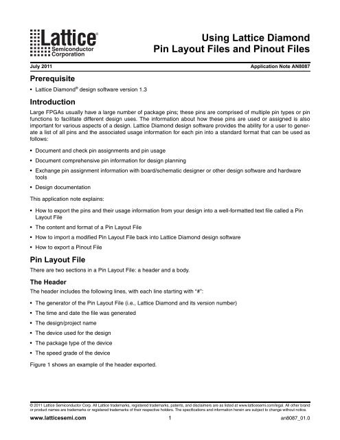
Introduction<br />
Large FPGAs usually have a large number of package pins; these pins are comprised of multiple pin types or pin<br />
functions to facilitate different design uses. The information about how these pins are used or assigned is also<br />
important for various aspects of a design. <strong>Lattice</strong> Diamond design software provides the ability for a user to generate<br />
a list of all pins and the associated usage information for each pin into a standard format that can be used as<br />
follows:<br />
Document and check pin assignments and pin usage<br />
Document comprehensive pin information for design planning<br />
Exchange pin assignment information with board/schematic designer or other design software and hardware<br />
tools<br />
Design documentation<br />
This application note explains:<br />
How to export the pins and their usage information from your design into a well-formatted text file called a Pin<br />
Layout File<br />
The content and format of a Pin Layout File<br />
How to import a modified Pin Layout File back into <strong>Lattice</strong> Diamond design software<br />
How to export a Pinout File<br />
Pin Layout File<br />
There are two sections in a Pin Layout File: a header and a body.<br />
The Header<br />
The header includes the following lines, with each line starting with “#”:<br />
The generator of the Pin Layout File (i.e., <strong>Lattice</strong> Diamond and its version number)<br />
The time and date the file was generated<br />
The design/project name<br />
The device used for the design<br />
The package type of the device<br />
The speed grade of the device<br />
Figure 1 shows an example of the header exported.<br />
Using <strong>Lattice</strong> Diamond<br />
Pin Layout Files and Pinout Files<br />
© 2011 <strong>Lattice</strong> <strong>Semiconductor</strong> Corp. All <strong>Lattice</strong> trademarks, registered trademarks, patents, and disclaimers are as listed at www.latticesemi.com/legal. All other brand<br />
or product names are trademarks or registered trademarks of their respective holders. The specifications and information herein are subject to change without notice.<br />
www.latticesemi.com 1 an8087_01.0
Using <strong>Lattice</strong> Diamond<br />
<strong>Lattice</strong> <strong>Semiconductor</strong> Pin Layout Files and Pinout Files<br />
Figure 1. Example of the Header Exported<br />
#Pin Layout Report file generated by <strong>Lattice</strong> Diamond Version 1.3.71<br />
#Generated at Tue May 31 14:08:25 2011<br />
#DESIGN = top<br />
#DEVICE = LFE3-70EA<br />
#PACKAGE = FPBGA484<br />
#SPEEDGRADE = 7<br />
The Body<br />
The body of the exported file includes all package pins and optionally their usage information.<br />
The first line of the body includes the field names for the columns of data which are exported to the Pin Layout File.<br />
The fields may vary by device. All fields for a chosen device can be seen in the Spreadsheet View, Port Assignments<br />
and Pin Assignments tabs in the Spreadsheet View in <strong>Lattice</strong> Diamond. Some commonly used fields that<br />
can be selectively exported for all devices include:<br />
Pin number<br />
Pin name<br />
Pin function<br />
Bank number<br />
Pin type<br />
I/O type, or I/O standard of the pin that was assigned<br />
Signal name: the design port/signal that was assigned to the pin, if available<br />
Direction: the direction of the signal/port that was assigned to the pin<br />
Some device-specific fields are:<br />
Pullmode<br />
Drive<br />
Slewrate<br />
PCIClamp<br />
Opendrain<br />
For detailed information and an explanation of each field, please refer to the <strong>Lattice</strong> Diamond User Guide, <strong>Lattice</strong><br />
Diamond online help, or the related device data sheet<br />
Beneath the first line in the Pin Layout File are the lines of information for all package pins with one pin per row.<br />
Each pin/row starts with its pin number, followed by user-selected pin usage information or fields. Each field occupies<br />
a column, and all fields are separated by a user-defined delimiter.<br />
User-selectable delimiters can include commas (,), semicolons (;), spaces ( ), and tabs ().<br />
The order of all exported fields (except the pin number) can be manually controlled when exporting the Pin Layout<br />
File through a graphical user interface, as shown in Figure 3.<br />
Figure 2 shows a few lines from the body of a Pin Layout File. Note that due to the limited space, not all columns<br />
from the example are shown here.<br />
2
Using <strong>Lattice</strong> Diamond<br />
<strong>Lattice</strong> <strong>Semiconductor</strong> Pin Layout Files and Pinout Files<br />
Figure 2. Example of the Body Exported<br />
# There are 19 columns in the table<br />
Pin Number, Pad Name, Function, IO Bank Number, Signal Name, Direction, Trace<br />
T17, PR61E_D, RLM1_GPLLT_IN_B, 3, , , 7426.660000, , , , , , , , , , , ,<br />
V20, PR61E_B, RLM1_GPLLT_FB_B, 3, , , 10963.890000, , , , , , , , , , , ,<br />
R17, PR61E_C, RLM1_GPLLT_IN_A, 3, CLK, Input, 6796.230000, LVCMOS33, OFF,<br />
V21, PR61E_A, RLM1_GPLLT_FB_A, 3, , , 10936.450000, , , , , , , , , , , ,<br />
Figure 3. Export Pin Layout File User Interface<br />
Exporting Pin Layout Files<br />
The Pin Layout File can be exported at any time during a project cycle, but it is recommended that you do so at one<br />
of the following three stages:<br />
1. Before Synthesis or Translation<br />
At this stage, all design information such as design ports/signals, pin assignments, etc., are not available<br />
and therefore, cannot be exported. A Pin Layout File exported at this time includes all physical pin information<br />
for all pins of the device selected in the project. A file exported at this time can, for example, be used to<br />
understand the pin-related information of the device, or can be used for early pin assignment and usage<br />
planning.<br />
A Pin Layout File exported at this stage can be considered as a device-specific pin information file.<br />
2. Pre- or Post-MAP<br />
At this stage, you may have already made some pin assignments, defined I/O standards, and so on. You<br />
can export these user-defined pin assignments along with all physical pin information into a second Pin<br />
Layout File. This exported file can be shared with, for example, a schematic or board designer for pin<br />
assignment review and changes. At a later time, the modified Pin Layout File can be imported back into<br />
<strong>Lattice</strong> Diamond design software to update the pin assignments.<br />
A Pin Layout File exported at this stage can be considered as a design-specific pin usage exchange file.<br />
3
Using <strong>Lattice</strong> Diamond<br />
<strong>Lattice</strong> <strong>Semiconductor</strong> Pin Layout Files and Pinout Files<br />
3. Post-PAR<br />
At this stage, if PAR is completed successfully, all design ports/signals are assigned, either by you or by<br />
PAR. If the PAR result is desirable, a third Pin Layout File can be exported. This file will include the final pin<br />
assignment information and can be handled over to, for example, the board designer as the pin assignment<br />
signoff. The exported file at this stage can also be used for final design documentation purposes.<br />
A Pin Layout File exported at this stage can be considered as a pin assignment sign-off file.<br />
To export a Pin Layout File at any time, follow these steps:<br />
1. In <strong>Lattice</strong> Diamond, open Spreadsheet View.<br />
2. Select the pull-down menu File > Export > Pin Layout File …<br />
3. In the Export Pin Layout File GUI, specify the file name as well as the columns and column delimiters you<br />
wish to use in your Pin Layout File (refer to Figure 3).<br />
For details, please refer to the <strong>Lattice</strong> Diamond User Guide or the <strong>Lattice</strong> Diamond online help<br />
Importing Pin Layout Files<br />
The pin assignments in the Pin Layout File may be modified outside of the <strong>Lattice</strong> Diamond environment by you or<br />
a schematic/board designer using a text editor or a spreadsheet editor. The modified Pin Layout File can then be<br />
imported back into <strong>Lattice</strong> Diamond design software to easily and quickly update the current pin assignments.<br />
Though you are free to import such a file at any time after the Translation process, there are some recommendations<br />
that you should follow:<br />
Since any committed pin assignment change done in Spreadsheet View will reset the Process flow, you should<br />
import a Pin Layout File after Synthesis/Translation and before MAP whenever possible.<br />
You should import a Pin Layout File into a project from where the Pin Layout File was exported. This will ensure<br />
the device used in both the file and the project are the same, and ports and signals defined in the file are synchronized<br />
with the project.<br />
You should not change any field names on the first line of the body, otherwise a new name may not be recognized<br />
and the import process might fail. Specifically, you should not change the name of the fields “Pin_Number”<br />
and “Signal_Name”.<br />
You may change port/signal names, or add new ports/signals to the file that will be imported. If you do so, make<br />
sure the new names exist in the project (you can check this through the Spreadsheet View, Port Assignments<br />
tab). Remember any signal/port that was defined in the Pin Layout File but does not exist in the project will not be<br />
imported and will be ignored.<br />
If you migrate a project to a new device, and the new device is pin migration compatible with the original device,<br />
you can import the Pin Layout File which was exported from the original project that used the old device. When<br />
doing this type of change, please make sure the “DEVICE” line in the header is changed to match the name of<br />
the new device prior to importing the Pin Layout File; otherwise the import process will fail.<br />
To import a Pin Layout File, the Translation process must complete successfully.<br />
In <strong>Lattice</strong> Diamond design software, follow these steps:<br />
1. In <strong>Lattice</strong> Diamond design software, open Spreadsheet View.<br />
2. Select the pull-down menu File > Export > Pin Layout File …<br />
3. Specify the name of the file to be imported and the column delimiter used in the file.<br />
For details, please refer to the <strong>Lattice</strong> Diamond User Guide or the <strong>Lattice</strong> Diamond design software online help.<br />
4
Using <strong>Lattice</strong> Diamond<br />
<strong>Lattice</strong> <strong>Semiconductor</strong> Pin Layout Files and Pinout Files<br />
Pinout File<br />
In addition to a Pin Layout File, you can also export a Pinout File for a specific device in <strong>Lattice</strong> Diamond design<br />
software. A device’s Pinout File (CSV) can be downloaded from the <strong>Lattice</strong> web site, or the information can be<br />
found in the device data sheet. Now you can also generate a Pinout File in <strong>Lattice</strong> Diamond design software.<br />
Unlike the Pin Layout File, for which you have multiple options to control the content and the format, a device Pinout<br />
File has the following characteristics:<br />
The content of a device Pinout File is device-specific and contains no information about a design.<br />
A Pinout File can be exported at any time, but the content is always the same.<br />
A Pinout File is always “comma separated”.<br />
A Pinout File cannot be imported into <strong>Lattice</strong> Diamond design software.<br />
A Pinout File contains the following two sections:<br />
– A header, which includes the generator information (i.e., <strong>Lattice</strong> Diamond version number), the generation<br />
time, the device name and the package type<br />
– A body, or pin information, which includes the following fields in the fixed order and may vary per device:<br />
- Index number<br />
- Pin/ball function<br />
- Pin type<br />
- Bank number<br />
- Dual function names<br />
- Differential definition<br />
- Pin number<br />
- DQS, and<br />
- I/O grouping<br />
To export a Pinout File, follow these steps:<br />
1. In <strong>Lattice</strong> Diamond, open Spreadsheet View.<br />
2. Select the pull-down menu File > Export > Pin Out File …<br />
3. Specify the filename and location to save the file.<br />
For details, please refer to the <strong>Lattice</strong> Diamond User Guide or <strong>Lattice</strong> Diamond online help.<br />
In <strong>Lattice</strong> Diamond design software version 1.3, only “bonded” pads (i.e., those pads bonded out to package pins)<br />
will be exported into a Pinout File; in the future releases “unbonded” pads will be included.<br />
<strong>Lattice</strong> CSV File<br />
For legacy design support purposes, <strong>Lattice</strong> Diamond 1.3 still supports <strong>Lattice</strong> CSV File import and export. <strong>Lattice</strong><br />
CSV File support may be removed in future software releases, thus it is strongly recommended to discontinue use<br />
of <strong>Lattice</strong> CSV Files.<br />
For detailed information about <strong>Lattice</strong> CSV Files, please refer to the <strong>Lattice</strong> Diamond User Guide, or <strong>Lattice</strong> Diamond<br />
online help.<br />
Additional Information<br />
For additional information about <strong>Lattice</strong> Diamond design software, please visit www.latticesemi.com, or send an<br />
email to sw_mktg@latticesemi.com.<br />
5
Using <strong>Lattice</strong> Diamond<br />
<strong>Lattice</strong> <strong>Semiconductor</strong> Pin Layout Files and Pinout Files<br />
Technical Support Assistance<br />
Hotline: 1-800-LATTICE (North America)<br />
+1-503-268-8001 (Outside North America)<br />
e-mail: techsupport@latticesemi.com<br />
Internet: www.latticesemi.com<br />
Revision History<br />
Date Version Change Summary<br />
July 2011 01.0 Initial release.<br />
6