Standards for the FREMO modular system
Standards for the FREMO modular system
Standards for the FREMO modular system

Create successful ePaper yourself
Turn your PDF publications into a flip-book with our unique Google optimized e-Paper software.
<strong>Standards</strong> <strong>for</strong> <strong>the</strong> <strong>FREMO</strong> <strong>modular</strong> <strong>system</strong><br />
Release: 2008-02-16<br />
Replaces:<br />
Written by: Bernd Schneider
<strong>FREMO</strong> americaN<br />
www.america-n.de<br />
Contents<br />
Page 2 of 11<br />
1 Preface and Introduction .................................................................................................... 3<br />
2 Notes on this version.......................................................................................................... 3<br />
3 Module structure ................................................................................................................ 3<br />
3.1 Geometry of module structure.................................................................................... 3<br />
3.2 End profile.................................................................................................................. 4<br />
3.3 Height of rail top ........................................................................................................ 4<br />
3.4 Module connection..................................................................................................... 4<br />
3.5 Color of side panels.................................................................................................... 5<br />
4 Track................................................................................................................................... 5<br />
4.1 Allowed track material ............................................................................................... 5<br />
4.2 Minimum radius ......................................................................................................... 5<br />
4.3 Clearances and track axis distances ........................................................................... 5<br />
4.4 Uncoupling magnets................................................................................................... 5<br />
4.5 Throw mechanisms and controls................................................................................ 6<br />
5 Rolling stock ...................................................................................................................... 6<br />
5.1 Wheelsets ................................................................................................................... 6<br />
5.2 Couplers ..................................................................................................................... 6<br />
5.3 Car weight .................................................................................................................. 6<br />
5.4 Motive power ............................................................................................................. 6<br />
5.5 Wea<strong>the</strong>ring ................................................................................................................. 6<br />
6 Landscape........................................................................................................................... 6<br />
6.1 Season, era and modeled region................................................................................. 6<br />
6.2 Grass fiber / landscaping material.............................................................................. 7<br />
6.3 Color of track and ballast ........................................................................................... 7<br />
6.4 Telephone poles.......................................................................................................... 7<br />
7 Electrical equipment........................................................................................................... 8<br />
7.1 Electrical connection to track work............................................................................ 8<br />
7.2 Electrical connection between modules ..................................................................... 8<br />
7.3 DCC booster............................................................................................................... 8<br />
7.4 LocoNet...................................................................................................................... 8<br />
8 Car cards............................................................................................................................. 8<br />
9 Datasheet & waybills ......................................................................................................... 9<br />
9.1 General ....................................................................................................................... 9<br />
9.2 9.2 Datasheet and car cards........................................................................................ 9<br />
9.3 Car card boxes at stations......................................................................................... 11<br />
10 Recommended materials .............................................................................................. 11<br />
11 Links............................................................................................................................. 11<br />
12 Contact ......................................................................................................................... 11
<strong>FREMO</strong> americaN<br />
www.america-n.de<br />
1 Preface and Introduction<br />
Page 3 of 11<br />
americaN is a module standard adopted by <strong>the</strong> <strong>FREMO</strong> (Friendscircle of European<br />
Modelrailroaders). Modules build to this standard resemble single-track standard gauge<br />
railroad lines in North America in N-scale (1:160). There are no restrictions on ei<strong>the</strong>r area or<br />
era.<br />
This document contains standards as well as recommended practices <strong>for</strong> building and<br />
detailing americaN modules. There are also standards <strong>for</strong> materials necessary <strong>for</strong> prototypeoriented<br />
operations, <strong>for</strong> example car cards and waybills. Important aspects of <strong>the</strong> “Track<br />
Warrant Control” operations (which is our preferred method) are described in a separate short<br />
reference. This document can be loaded from <strong>the</strong> homepage of americaN.<br />
The americaN module <strong>system</strong> was developed in 2001 because <strong>the</strong> initiators felt that <strong>the</strong><br />
already existing module <strong>system</strong>s, NTRAK and oneTRAK no longer reflected <strong>the</strong> current<br />
philosophy of <strong>modular</strong> model railroading. In <strong>the</strong> americaN <strong>system</strong> <strong>the</strong> use of a prototypical<br />
traffic control <strong>system</strong>, as well as simulation of traffic flow with car cards and waybills, is very<br />
important. This overall concept already existed with <strong>FREMO</strong> module <strong>system</strong>s. For <strong>the</strong><br />
americaN standard, many ideas were taken from <strong>FREMO</strong> H0(USA) and fremo-N. One o<strong>the</strong>r<br />
important aspect of americaN is <strong>the</strong> use of commercial track and turnouts.<br />
The main characteristics of americaN are:<br />
- free module geometry,<br />
- height of rail top above ground 1300 mm,<br />
- use of NMRA-DCC and LocoNet,<br />
- prototype-oriented operations (Track Warrant Control)<br />
- use of car cards and waybills.<br />
2 Notes on this version<br />
This is <strong>the</strong> first release of <strong>the</strong> americaN standard in <strong>the</strong> English language. It is a translation of<br />
<strong>the</strong> 2007-11-01 German standard. Modules built to preceding standards are allowed to be<br />
used, even if <strong>the</strong>y do not currently follow <strong>the</strong> norm in all details.<br />
Changes in this version are:<br />
- additional remarks on end profiles<br />
- definition of a standard <strong>for</strong> electrostatic grass and landscape<br />
- revision of waybills, now with day of week indication<br />
3 Module structure<br />
3.1 Geometry of module structure<br />
Length, width and angle of a module can be freely chosen, as long as <strong>the</strong> minimum radius of<br />
1000mm on <strong>the</strong> main track is maintained. With respect to transportability, <strong>the</strong> length of a<br />
single segment should be kept below 1200 mm.
<strong>FREMO</strong> americaN<br />
www.america-n.de<br />
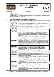
3.2 End profile<br />
Image 1<br />
Page 4 of 11<br />
The underlined items are identical to <strong>the</strong> dimensions of <strong>the</strong> <strong>FREMO</strong> end profile N90, so<br />
mechanical compatibility to o<strong>the</strong>r <strong>FREMO</strong> <strong>system</strong>s in N scale is maintained. The values in<br />
brackets refer to wide-spread, commercially available products.<br />
NOTE: The 8-mm holes are NOT vertically centered! It is suggested to drill <strong>the</strong>se holes only<br />
after track has been laid. A self-made cardboard template may be very useful.<br />
3.3 Height of rail top<br />
The rail top is at a height of 1300 mm above floor. The module legs must have <strong>the</strong> possibility<br />
to adjust height <strong>for</strong> +/-20 mm. Modules with a length of 500 mm and longer must be able to<br />
stand by <strong>the</strong>mselves.<br />
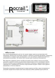
3.4 Module connection<br />
The modules are mechanically connected with nuts, bolts (both M6 or 1/4") and appropriate<br />
washers. It must be possible to tighten <strong>the</strong> screws and nuts without tools, so its mandatory to<br />
use ei<strong>the</strong>r wing screws, thumb screws or eye bolts and wing nuts. Rail joiners or connecting<br />
tracks are not used. The rails end flush or with a set back up to 0,2 mm at a RIGHT ANGLE<br />
to <strong>the</strong> end plate. For improved mechanical stability <strong>the</strong> rails must be soldered to brass screws<br />
or PCB ties at <strong>the</strong> end of <strong>the</strong> module. It is important to check <strong>the</strong> gauge after completion! The<br />
railheads are to be chamfered at <strong>the</strong> module ends (see image 2).<br />
Rails must not run over <strong>the</strong> complete length of a module. For humidity compensation, a cut<br />
through both rails in <strong>the</strong> middle of <strong>the</strong> module is mandatory.
<strong>FREMO</strong> americaN<br />
www.america-n.de<br />
Image 2<br />
Page 5 of 11<br />
3.5 Color of side panels<br />
The side panels must be painted in a semi-gloss, beige color RAL 1001 Beige or equivalent.<br />
4 Track<br />
4.1 Allowed track material<br />
The maximum allowed height of <strong>the</strong> visible rail is 1,4 mm, which is Code 55. At <strong>the</strong> moment<br />
<strong>the</strong>re are two optically satisfying products resembling North American trackwork:<br />
- Atlas Code 55<br />
- Micro Engineering Code 55<br />
The Micro Engineering Code 55 flex track has <strong>the</strong> advantage that MT wheelsets with high<br />
flanges can run on it without hopping. Thus, <strong>for</strong> modules without turnouts this track is <strong>the</strong><br />
best we can recommend. All o<strong>the</strong>r trackwork should be made of Atlas Code 55 flex track and<br />
#7 turnouts or greater. Atlas turnouts are “DCC-friendly” without modifications. The frog of<br />
<strong>the</strong> #5 Atlas turnout is problematic, and requires work in order to be con<strong>for</strong>m to NMRA<br />
standard S-3.2 (Trackwork, Standard Scales).<br />
Peco Streamline Code 55 track and turnouts can also be used. Turnouts must be modified that<br />
<strong>the</strong> frog has its own current supply and is not supplied through <strong>the</strong> points exclusively.<br />
Custom-made trackwork is also acceptable if it con<strong>for</strong>ms to NMRA standard S-3.2. For<br />
compatibility with MT wheelsets, flange clearance H must be at least 0.8 mm.<br />
4.2 Minimum radius<br />
Main track curves must be built with a minimum radius of 1000 mm.<br />
4.3 Clearances and track axis distances<br />
Clearances must be con<strong>for</strong>m to NMRA standard S-7, and S-8 (using Class 1a rolling stock).<br />
4.4 Uncoupling magnets<br />
Uncoupling magnets are not allowed due to <strong>the</strong> possibility of unintended train separation. For<br />
Uncoupling, <strong>the</strong> Rix Pick N scale uncoupling tool or a similar device is used.
<strong>FREMO</strong> americaN<br />
www.america-n.de<br />
Page 6 of 11<br />
4.5 Throw mechanisms and controls<br />
A location must be easily operable <strong>for</strong> crews unfamiliar with <strong>the</strong> “territory.” Thus, turnout<br />
controls (mechanical or electrical) should be close to <strong>the</strong> turnout. Switching locations in<br />
curves, as well as junctions, must be operable from both sides of <strong>the</strong> module. Mechanical<br />
<strong>system</strong>s are especially well suited <strong>for</strong> this.<br />
Being able to operate from both sides of <strong>the</strong> module is very helpful in planning <strong>for</strong> successful<br />
arrangement of modules.<br />
5 Rolling stock<br />
5.1 Wheelsets<br />
The wheelsets must be able to roll over Atlas Code 55 turnouts and flex track without<br />
touching <strong>the</strong> rail spikes.<br />
5.2 Couplers<br />
MicroTrains or compatible couplers which can easily be opened with <strong>the</strong> Rix Picks are<br />
mandatory. Kato or older Accumate couplers do not work properly!<br />
As uncoupling magnets are not allowed, it is not necessary to adjust <strong>the</strong> trip pins. In unit train<br />
cars (passenger or freight) <strong>the</strong> couplers can be chosen freely. It is recommended practice to<br />
mount <strong>the</strong> couplers on <strong>the</strong> car body instead of on <strong>the</strong> trucks, as it provides smoo<strong>the</strong>r operation.<br />
5.3 Car weight<br />
Car weight must follow NMRA Recommended Practice RP-20.1: Initial weight 1/2 oz. + 0.15<br />
oz/inch of car body length. This equals 14g inital weight plus 1.7g per cm car body length.<br />
5.4 Motive power<br />
As americaN layouts are operated with NMRA-DCC, all motive power must be suited with an<br />
appropriate decoder. The speed curve must be adjusted in a way that maximum speed with<br />
cars on level track is approximately 60 mph (with reference to 14V track voltage, see 7.3).<br />
The half-way throttle position should be represented with about half of maximum speed.<br />
Acceleration and deceleration delay are to be switched off (CV3 and CV4), unless <strong>the</strong>y can be<br />
toggled with FRED throttle control and are noted on <strong>the</strong> loco data sheet. If <strong>the</strong> decoder<br />
provides automatic change between analog and digital mode, that function must also be<br />
deactivated.<br />
5.5 Wea<strong>the</strong>ring<br />
Wea<strong>the</strong>ring is deemed a very important factor <strong>for</strong> giving a realistic flair on a model railroad.<br />
There<strong>for</strong>e all rolling stock should show some wea<strong>the</strong>ring. Different grades of wea<strong>the</strong>ring are<br />
prototypical and thus welcome.<br />
6 Landscape<br />
6.1 Season, era and modeled region<br />
The modeled season is summer. Nei<strong>the</strong>r a specific region nor era is specified, but if enough<br />
rolling stock is available <strong>for</strong> a specific era, meetings will take advantage.
<strong>FREMO</strong> americaN<br />
www.america-n.de<br />
Page 7 of 11<br />
6.2 Grass fiber / landscaping material<br />
For <strong>the</strong> US Convention 2007 in Rodgau, Germany, <strong>the</strong> better part of <strong>the</strong> finished modules got<br />
a major rework with electrostatically applied grass fibers. The base mixture consists of one<br />
part Heki Sommerwiese 3360, one part Heki Wildgras 3367, and one part Heki Winterboden<br />
3363. This type of landscaping is to be preferred on reworks and newly built modules.<br />
As not everyone has access to an electrostatic applying tool <strong>the</strong>re are o<strong>the</strong>r base mixtures of<br />
flockage allowed:<br />
- <strong>for</strong> arid zones: two parts Woodland Scenics T50 earth blend, two parts T43 yellow<br />
grass, one part T44 burnt grass;<br />
- <strong>for</strong> humid zones: two parts T44 burnt grass, one part T45 green grass, two parts T50<br />
earth blend.<br />
6.3 Color of track and ballast<br />
The main line (rail and ties) must be of dark grey color (we recommend Tamiya XF-63<br />
German Grey). Ballast must be of middle grey color (we recommend ASOA Diabas N scale<br />
nr. 1409).<br />
All o<strong>the</strong>r track work should resemble track maintained to a lesser degree than <strong>the</strong> main line.<br />
Rail and ties should be colored in brown. Colors called “rust” are normally way too red and<br />
<strong>the</strong>re<strong>for</strong>e are not to be used!<br />
6.4 Telephone poles<br />
Poles are a simple way <strong>for</strong> giving some 3D appearance to ra<strong>the</strong>r flat modules. Thus, pole lines<br />
are to be installed (we recommend Atlas #2801). The poles must be painted grey, <strong>the</strong><br />
insulators white or green. If <strong>the</strong> module has a distinct “viewing side,” <strong>the</strong> poles should be<br />
located behind <strong>the</strong> track. The number of poles n is calculated as follows: n = length-of-module<br />
/ 25 cm (round to closest number). The distance a from <strong>the</strong> module end to <strong>the</strong> first pole<br />
<strong>the</strong>re<strong>for</strong>e is a = length-of-module/(2n). Distance between poles is 2a.
<strong>FREMO</strong> americaN<br />
www.america-n.de<br />
7 Electrical equipment<br />
Page 8 of 11<br />
7.1 Electrical connection to track work<br />
Because of <strong>the</strong> high specific resistance of rail, <strong>the</strong> track current must primarily pass through a<br />
feeder line, or track bus, parallel to <strong>the</strong> tracks and be fed into <strong>the</strong> rail in more than one<br />
location. The cross section of <strong>the</strong> track bus must be at least 0.75 mm 2 or 18 AWG in order to<br />
minimize voltage drop. The short, feeder connections from <strong>the</strong> track bus to <strong>the</strong> rails can be<br />
made with reasonably thin wire, such as <strong>the</strong> individual wires from phone or computer network<br />
cables. Each rail profile piece must have its own connection to <strong>the</strong> track bus, as rail joiners<br />
tend to oxidize with time.<br />
7.2 Electrical connection between modules<br />
As <strong>the</strong>re are no rail joiners between modules, current must be passed from module to module<br />
using cables. The connection is made with 4 mm banana plugs. The right rail (in running<br />
direction toward <strong>the</strong> end of <strong>the</strong> module) must use a male connector, <strong>the</strong> left-hand rail a<br />
female. This ensures correct connection. The cables must be at least 30 cm or 1ft long (from<br />
<strong>the</strong> module ends), in order to ensure easy connecting. Stackable 4mm plugs must be used <strong>for</strong><br />
connection with boosters anywhere on <strong>the</strong> layout.<br />
7.3 DCC booster<br />
Bigger yards and stations must have <strong>the</strong>ir own LocoNet-compatible booster. Track voltage<br />
must be set between 13 and 15 Volts.<br />
7.4 LocoNet<br />
The LocoNet network is separately made from LocoNet boxes and compliant cables, so <strong>the</strong>re<br />
is no need to provide LocoNet connections in <strong>the</strong> modules.<br />
8 Car cards<br />
Every freight car used in an operating session must have its own car card, providing <strong>the</strong><br />
following in<strong>for</strong>mation:<br />
- name of railroad<br />
- car number<br />
- car type<br />
- AAR type<br />
It is recommended to include an indication in what direction <strong>the</strong> empty car should be returned<br />
(east or west). For easy identification it would be nice to have a picture of <strong>the</strong> car on <strong>the</strong> front<br />
of <strong>the</strong> card.<br />
Groups of cars which travel as units and are not separated during a session can have a single<br />
card <strong>for</strong> <strong>the</strong> whole group (coal or cement unit trains, <strong>for</strong> example).<br />
Dimension of car cards: height 100 to 105 mm, width 54 to 60 mm and pocket depth 38 to 40<br />
mm.<br />
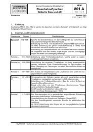
It is recommended to print <strong>the</strong> car card on index board, <strong>for</strong> example Brunnen Karteikarten<br />
unliniert, Art.-Nr. 10-22 400 10. Templates in MS Excel <strong>for</strong>mat are available on <strong>the</strong> americaN<br />
homepage. On image 3 you can see three different car cards: at left an older americaN carcard,
<strong>FREMO</strong> americaN<br />
www.america-n.de<br />
Page 9 of 11<br />
in <strong>the</strong> middle <strong>the</strong> actual MS Excel version (still without picture of <strong>the</strong> car) and to <strong>the</strong> right a<br />
commercially available card from Micro-Mark.<br />
Image 3<br />
9 Datasheet & waybills<br />
9.1 General<br />
Each location that generates or receives freight must have a datasheet. This must be provided<br />
at meetings. Additionally, <strong>the</strong> owner of <strong>the</strong> location must provide <strong>the</strong> necessary waybills.<br />
These waybills don’t have to be made <strong>for</strong> each meeting, but can be used again.<br />
9.2 9.2 Datasheet and car cards<br />
Our datasheet is based on a Bahnhofsdatenblatt that was introduced in <strong>the</strong> <strong>FREMO</strong>-Hp1magazine<br />
2/2004 by Knut Habicht and Bernd Schmedes. The major difference is <strong>the</strong> listing of<br />
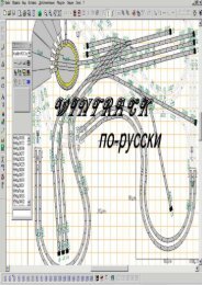
all in- and outbound freights <strong>for</strong> all spots per operation day. Design and content should be<br />
illustrated on <strong>the</strong> basis of <strong>the</strong> extract of <strong>the</strong> data sheet <strong>for</strong> Appaloosa Junction in image 4.<br />
On top left is a schematic track plan with named tracks. To <strong>the</strong> right is <strong>the</strong> approximate length<br />
of <strong>the</strong> sidings. The most important part is <strong>the</strong> chart. The “Track” column is <strong>the</strong> same identifier<br />
as in <strong>the</strong> track plan. If a track has more than one spot, <strong>the</strong>se spots are listed separately in <strong>the</strong><br />
column “Spot.” According to <strong>the</strong> available track length, <strong>the</strong>re is one row <strong>for</strong> one car length at<br />
a specific spot. For example <strong>the</strong> team track has four rows because of its length <strong>for</strong> four cars.<br />
The ramp at <strong>the</strong> team track is mentioned in a separate row.<br />
The freights are treated similarly, one row <strong>for</strong> every type of freight. If <strong>the</strong>re are more different<br />
types of freights than track capacity, <strong>the</strong> track capacity is mentioned additionally in <strong>the</strong><br />
column “Spot.” For example, <strong>the</strong> ramp at Cascades Cookies has only a capacity of two cars<br />
but four different types of loads.
<strong>FREMO</strong> americaN<br />
www.america-n.de<br />
Page 10 of 11<br />
In <strong>the</strong> “In” row, <strong>the</strong> inbound goods are listed; in <strong>the</strong> “AAR type” row, <strong>the</strong> necessary car type;<br />
and in <strong>the</strong> “Out” row, <strong>the</strong> outbound goods are described.<br />
The following seven double rows are <strong>the</strong> weekdays. Here <strong>the</strong> owner registers at which<br />
weekday what good has to be delivered or collected to or from what spot.<br />
On <strong>the</strong> basis of <strong>the</strong> datasheet, <strong>the</strong> owner of <strong>the</strong> location makes his set of waybills. Waybills or<br />
empty car orders must show <strong>the</strong> weekday. (See new MS Excel Sheet on <strong>the</strong> americaN<br />
homepage).<br />
With <strong>the</strong> datasheet and <strong>the</strong> waybills it is now quite easy to build up <strong>the</strong> trains in <strong>the</strong> staging<br />
yards. The “yard master” takes all waybills and combined empty car orders/waybills to <strong>the</strong><br />
appropriate staging yard, from where a specific spot is reached. Now he just has to look <strong>for</strong> a<br />
car with its car-card, and inserts <strong>the</strong> waybill or empty car order in <strong>the</strong> car-card’s pocket.<br />
The “in” and “out” columns <strong>for</strong> <strong>the</strong> team track and <strong>the</strong> interchange track were intentionally<br />
not filled out. To have a possibility to vary <strong>the</strong> operation sessions in some degree, it is <strong>the</strong><br />
yard master’s task to pick some available waybills <strong>for</strong> <strong>the</strong>se spots and to put <strong>the</strong> cars in <strong>the</strong><br />
right train. So waybills must also exist <strong>for</strong> <strong>the</strong>se two spots, but without a marking <strong>for</strong> a<br />
specific weekday.<br />
We use four types of waybills:<br />
- waybill <strong>for</strong> inbound freight (one-cycle)<br />
- combined empty car order / waybill (two-cycle)<br />
- interchange waybill (two-cycle)<br />
- run through waybill (two-cycle)<br />
The first two are normal bills <strong>for</strong> freight to local customers. On interchange waybills only <strong>the</strong><br />
receiving traffic location is mentioned, car type and content is not important. Run through<br />
waybills are <strong>for</strong> cars running from one staging yard to <strong>the</strong> o<strong>the</strong>r.<br />
The waybills are color-coded. Red denotes East, and yellow stands <strong>for</strong> West. Bigger traffic<br />
locations can get <strong>the</strong>ir own color code; <strong>for</strong> example, Appaloosa Junction has “green.”
<strong>FREMO</strong> americaN<br />
www.america-n.de<br />
Page 11 of 11<br />
9.3 Car card boxes at stations<br />
Every station or site must have a box <strong>for</strong> car cards. The pocket should be 65 mm wide. Every<br />
customer should have its own compartment with an appropriate labelling. Stations should also<br />
have an “off spot” compartment <strong>for</strong> cars that could not be spotted and an “outbound”<br />
compartment <strong>for</strong> cars that were already switched from <strong>the</strong>ir loading/unloading spot.<br />
10 Recommended materials<br />
Here a short overview over <strong>the</strong> material recommendations in this standard. Wal<strong>the</strong>rs-Numbers<br />
are marked with this symbol: #.<br />
Asoa Diabas ballast N 1409 (200ml)<br />
Atlas Telephone Poles # 150-2801<br />
Rix N Scale Uncoupling Tool # 628-24<br />
Tamiya XF-63 -- German Grey XF-63<br />
Heki summer grass 3360<br />
Heki wild grass 3367<br />
Heki winter soil 3363<br />
Woodland Scenics T43 - Fine Turf -- Yellow Grass # 785-43<br />
Woodland Scenics T44 - Fine Turf -- Burnt Grass # 785-44<br />
Woodland Scenics T45 - Fine Turf -- Green Grass # 785-45<br />
Woodland Scenics T50 - Blended Turf -- earth # 785-50<br />
11 Links<br />
ASOA www.asoa.de<br />
Atlas www.atlasrr.com<br />
<strong>FREMO</strong> www.fremo.org<br />
NMRA www.nmra.org<br />
Rix www.rixproducts.com<br />
Tamiya www.dickietamiya.com<br />
Wal<strong>the</strong>rs www.wal<strong>the</strong>rs.com<br />
Woodland S. www.woodlandscenics.com<br />
12 Contact<br />
Bernd Schneider<br />
Beate-Paulus-Str. 2<br />
70806 Kornwes<strong>the</strong>im<br />
Germany<br />
Tel: +49 (0) 151 10 72 31 89<br />
homepage: www.america-n.de<br />
email: kontakt2008@america-n.de