Naval Gas ball valves - kaehler-armaturen.de
Naval Gas ball valves - kaehler-armaturen.de
Naval Gas ball valves - kaehler-armaturen.de

Create successful ePaper yourself
Turn your PDF publications into a flip-book with our unique Google optimized e-Paper software.
NAVAL<br />
<strong>Gas</strong> <strong>ball</strong> <strong>valves</strong>
PN40 4<br />
PN25<br />
PN16<br />
MPa<br />
3<br />
2<br />
1<br />
Pressure/temperature curves<br />
(Do not use for steam)<br />
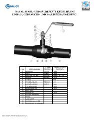
NAVAL GAS BALL VALVES<br />
<strong>Naval</strong> <strong>Gas</strong> <strong>ball</strong> <strong>valves</strong> are <strong>de</strong>signed for shut-off applications in natural gas pipelines. All <strong>valves</strong><br />
fulfil the requirements of European Pressure directive (97/23/EY) and are manufactured to<br />
category lll.(module H). <strong>Naval</strong> Oy has a certified quality system ISO 9001 and certified<br />
environmental management system ISO 14001. <strong>Naval</strong> gas <strong>valves</strong> can upon request be<br />
manufactured in accordance with the EU ATEX-directives (94/9/EC), equipment group ll. The<br />
ATEX-requirement shall always be mentioned in the inquiry and or<strong>de</strong>r.<br />
DESIGN:<br />
CHARACTERISTICS:<br />
The valve has all-wel<strong>de</strong>d body and is fitted with carbonreinforced<br />
Teflon seals which are long-lasting against<br />
frequent operation, impurities and chemicals.<br />
A ground and polished stainless steel <strong>ball</strong> gives easy<br />
turning and reliable operation over many years.<br />
A floating <strong>ball</strong> construction is used. Bevel spring washers<br />
keep the seals pressed against the <strong>ball</strong> to ensure that the<br />
valve remains leak- tight regardless of pressure fluctuations.<br />
The blow-out proof stem is sealed with 2 O-rings. In<br />
smaller <strong>valves</strong>, the upper one can be changed and in<br />
sizes 65 to 150 both can be changed. The Teflon thrust<br />
washer between the stem shoul<strong>de</strong>r and stem housing also<br />
acts as a seal.<br />
Stem housings of DN65 <strong>valves</strong> and above are fitted with<br />
stainless steel bearings.<br />
-40°C 0 +50 +100 +150 +200<br />
For temperatures below -20°C, please mention separately when or<strong>de</strong>ring.<br />
11<br />
4<br />
9<br />
10<br />
The valve needs no servicing - no adjustment or lubrication<br />
and is easy to install, long working life with low running<br />
costs.<br />
It is easy to insulate because of the long, circular stem<br />
housing.<br />
The operating lever is <strong>de</strong>tachable and can be re-positioned<br />
at 180 °<br />
Heavy and unreliable cast components are not used in the<br />
construction of the valve body.<br />
It is easy to retrofit actuating equipment.<br />
8 12<br />
6 7 5 3<br />
2<br />
1<br />
13<br />
MATERIALSPECIFICATION<br />
ITEM DESCRIPTION MATERIAL<br />
1. Body Carbon steel P235GH<br />
2. Stem Housing Carbon steel P335NH<br />
3. Ball Stainless steel 1.4301<br />
4. Stem Stainless steel 1.4305<br />
5. Seal Teflon PTFE+C<br />
6. Bevel washer Spring steel<br />
7. Support ring Stainless steel<br />
8. Screw Steel<br />
9. O-ring NBR<br />
10. Thrust washer Teflon PTFE<br />
11. Stop Casted steel 1.4301<br />
12. Handle Zinc-plated steel<br />
13. End pipe Carbon steel P235GH
D2<br />
D1<br />
D<br />
L<br />
H1<br />
WITH BUTT WELD CONNECTIONS<br />
DN PN NAVAL No L D D1 D2 H B H1 Weight(kg)<br />
10 40 280 402 230 10 17,2 33,7 98 145 22 0,5<br />
15 40 280 403 230 10 21,3 33,7 98 145 22 0,5<br />
20 40 280 405 230 15 26,9 42,4 103 145 23 0,7<br />
25 40 280 406 230 20 33,7 48,3 118 145 34 1,0<br />
32 40 280 407 260 25 42,4 60,3 121 145 33 1,4<br />
40 40 280 408 260 32 48,3 70,0 120 190 43 1,8<br />
50 40 280 409 300 40 60,3 88,9 127 190 44 2,6<br />
B<br />
H<br />
65 25 280 410 300 50 76,1 101,6 170 280 62 4,4<br />
80 25 280 411 300 65 88,9 121,0 185 280 68 5,6<br />
100 25 280 412 325 80 114,3 146,0 210 280 101 8,4<br />
125 16 280 413 325 100 139,7 177,8 253 400 101 13,4<br />
150 16 280 414 350 125 168,3 219,1 273 600 107 18,0<br />
200 16 280 416 390 150 219,1 273,0 300 900 123 36,3<br />
250 16 280 417 520 200 273,0 355,6 345 1200 122 72,0<br />
We recommend gear operation for <strong>valves</strong> 125 mm and larger.<br />
D2<br />
D1<br />
D<br />
GEAR-OPERATED<br />
C B<br />
DN PN NAVAL No L D D1 D2 H B C H1 Weight(kg)<br />
125 16 280 433 325 100 139,7 177,8 309 145 50 101 18<br />
150 16 280 434 350 125 168,3 219,1 330 145 50 107 23<br />
200 16 280 436 390 150 219,1 273 398 196 75 123 46<br />
250 16 280 437 520 200 273,0 355 451 236 100 122 87<br />
300 16 280 438 635 250 323,9 406 572 280 193 155 193<br />
L<br />
H1<br />
H<br />
D2<br />
D1<br />
D<br />
D2<br />
D1<br />
D<br />
L<br />
L<br />
WITH BUTT WELD CONNECTION/FEMALE PIPE THREADS<br />
DN PN NAVAL No L D D1 D2 D3 H B H1 Weight(kg)<br />
15 40 280 003 158 10 R 1/2 33,7 21,3 98 145 22 0,5<br />
20 40 280 005 165 15 R 3/4 42,4 26,9 103 145 23 0,6<br />
25 40 280 006 172 20 R 1 48,3 33,7 118 145 34 0,9<br />
32 40 280 007 195 25 R 1 1/4 60,3 42,4 121 145 33 1,2<br />
40 40 280 008 205 32 R 1 1/2 70,0 48,3 120 190 43 1,7<br />
50 40 280 009 240 40 R 2 88,9 60,3 127 190 44 2,3<br />
DN PN NAVAL No L D D1 D2 H B H1 Weight(kg)<br />
15 40 280 153 85 10 R 1/2 33,7 98 145 22 0,5<br />
20 40 280 155 100 15 R 3/4 42,4 103 145 23 0,5<br />
25 40 280 156 115 20 R 1 48,3 118 145 34 0,7<br />
32 40 280 157 130 25 R 1 1/4 60,3 121 145 33 0,9<br />
40 40 280 158 150 32 R 1 1/2 70,0 120 190 43 1,5<br />
50 40 280 159 180 40 R 2 88,9 127 190 44 2,1<br />
H1<br />
H1<br />
WITH FEMALE PIPE THREADS<br />
D<br />
B<br />
B<br />
D3<br />
H<br />
H<br />
D1<br />
D<br />
L<br />
L<br />
H1<br />
B<br />
D2<br />
D3<br />
WITH FLANGES<br />
D1<br />
C B<br />
DN PN NAVAL No L D D1 D2 D3 H B H1 Weight(kg)<br />
15 40 280 503 130 10 95 65 14 98 145 22 1,9<br />
20 40 280 505 150 15 105 75 14 103 145 23 2,7<br />
25 40 280 506 160 20 115 85 14 118 145 34 3,3<br />
32 40 280 507 180 25 140 100 18 121 145 33 5,0<br />
40 40 280 508 200 32 150 110 18 120 190 43 6,0<br />
50 40 280 509 230 40 165 125 18 127 190 44 7,9<br />
65 16 280 510 270 50 185 145 18 170 280 62 10,0<br />
80 16 280 511 280 65 200 160 18 185 280 68 12,5<br />
100 16 280 512 300 80 220 180 18 210 280 101 18,8<br />
125 16 280 513 325 100 250 210 18 253 400 101 24,3<br />
150 16 280 514 350 125 285 240 22 273 600 107 31,5<br />
200 16 280 516 400 150 340 295 22 300 900 123 55,1<br />
250 16 280 517 530 200 405 355 26 345 1200 122 97,8<br />
WITH FLANGES AND WITH GEAR<br />
H<br />
DN PN NAVAL No L D D1 D2 D3 H B C H1 Weight(kg)<br />
125 16 280 533 325 100 250 210 18 309 145 50 101 29<br />
150 16 280 534 350 125 285 240 22 330 145 50 107 36<br />
200 16 280 536 400 150 340 295 22 398 196 75 123 65<br />
250 16 280 537 530 200 405 355 26 451 236 100 122 113<br />
300 16 280 538 630 250 460 406 26 572 280 193 155 229<br />
Flanges: SFS 2123, SS 335, DIN 2501, ISO 2084<br />
Face to face dimensions<br />
according to: DN15-50 DIN 3202/F1 DN250-300 DIN 3202/F15<br />
DN65-200 DIN 3202/F5<br />
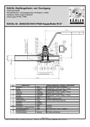
<strong>Gas</strong> valve with exten<strong>de</strong>d stem for un<strong>de</strong>rground services<br />
with PE-ends. Stem height according to specification.<br />
DN PN NAVAL No L D D1<br />
32 8 280 801 1058 40 33,7<br />
40 8 280 802 1084 50 33,7<br />
50 8 280 803 1126 63 33,7<br />
80 8 280 805 1100 90 42,4<br />
100 8 280 807 1171 110 60,3<br />
100 8 280 808 1181 125 60,3<br />
150 8 280 809 1324 160 60,3<br />
150 8 280 810 1356 180 60,3<br />
200 8 280 811 1358 200 88,9<br />
H1<br />
H
- All steel parts covered for outsi<strong>de</strong> corrosion<br />
with PE coating<br />
- PE ends suitable for all welding methods<br />
- Valve is operated with T-key, portable gear or<br />
worm gear<br />
- ISO 9001<br />
- PED<br />
- GOST<br />
- ATEX<br />
GAS VALVE FOR PE-PIPES<br />
GAS- AND QUALITY APPROVALS
SELECTION TABLE OF ACTUATORS<br />
DN PN Pneumatic, Pneumatic, Electric actuator Electric actuator<br />
spring return double acting Auma Bernard<br />
RC RC<br />
10 40 RC210-SR RC210-DA SG03-11 OA3<br />
15 40 RC210-SR RC210-DA SG03-11 OA3<br />
20 40 RC210-SR RC210-DA SG03-11 OA3<br />
25 40 RC220-SR RC210-DA SG03-11 OA3<br />
32 40 RC220-SR RC210-DA SG03-11 OA3<br />
40 40 RC230-SR RC220-DA SG04-11 OA6<br />
50 40 RC230-SR RC220-DA SG04-11 OA6<br />
65 25 RC240-SR RC220-DA SG05-11 OA8<br />
80 25 RC240-SR RC230-DA SG05-11 OA15<br />
100 25 RC250-SR RC240-DA SG07-22 AS18<br />
125 16 RC260-SR RC240-DA SG07-22 AS25<br />
150 16 RC270-SR RC260-DA SG10-45 AS50<br />
200 16 RC270-SR RC260-DA SG12-63 BS100<br />
250 16 RC280-SR RC270-DA SA07.1-GSM100.3 SRA6 RS250<br />
300 16 RC280-DA SA07.5-GSM125.3 SRC RS600<br />
Electric actuators are available with one or three phase motors. The valve and<br />
actuator compination can upon request be manufactured in accordance<br />
with the EU ATEX-directives.<br />
DN25 + Bernard OA3<br />
Flow Control Division<br />
DN80 + RC230-DA<br />
NAVAL OY, P.O.Box 32, FIN-23801 Laitila, FINLAND,<br />
tel. +358-2-85 091, fax +358-2-856 506,<br />
e-mail: naval@naval.fi, www.naval.fi<br />
DN200 + Auma SG12-63<br />
We reserve the right for alterations. NLENBR0026-02