ES721 ISO40 7 kW NL - HSD
ES721 ISO40 7 kW NL - HSD
ES721 ISO40 7 kW NL - HSD

Create successful ePaper yourself
Turn your PDF publications into a flip-book with our unique Google optimized e-Paper software.
<strong>HSD</strong><br />
§ 9 INSTALLAZIONE<br />
<strong>HSD</strong> S.p.a. does not and cannot know the methods adopted by the user to install<br />
the spindles. It is therefore the responsibility of the installer or end user to carry<br />
out a risk analysis for each specific installation type and the methods adopted.<br />
It is furthermore the responsibility of the installer to ensure that there is sufficient<br />
protection against accidental contact with moving parts.<br />
The installer and user must also take all the necessary precautions to prevent<br />
other types of risk, particularly those deriving from foreign bodies entering the<br />
equipment, contact with explosive, flammable, toxic or high temperature gases.<br />
Risks relating to maintenance operations must also be taken into consideration.<br />
Maintenance must be performed in conditions of maximum safety, with<br />
electrospindle power switched off and with no risk of tool movement.<br />
9.1 UTILITY SUPPLIES IN THE FACTORY<br />
All preparation work for installation of the electrospindle is the responsibility of the Customer (e.g.<br />
the provision of electricity and compressed air lines, etc.).<br />
The electrical power line to the electrospindle must have sufficient capacity. Connection to the<br />
supply network must be performed by qualified electricians. The Customer is responsible for the<br />
entire electrical supply as far as the electrospindle connectors.<br />
The Customer's attention is drawn to the need to ensure that all safety aspects relating to the<br />
grounding of the electrospindle are complied with.<br />
The ground system must furthermore comply with the standards applicable in the country or state<br />
of installation and must be checked regularly by qualified electricians.<br />
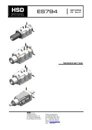
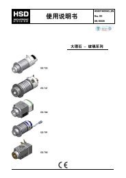
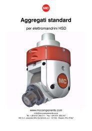
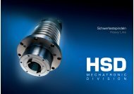
9.2 FIXING<br />
(See figures of chapter § 8)<br />
To fix the electrospindle directly onto the machinery use n°8 M8 stainless steel screws.<br />
To fix an electrospindle equipped with the fixing support use n°8 M10 stainless steel screws and<br />
n°2 reference pins.<br />
9.3 HYDRAULIC CONNECTIONS<br />
See the figures in chapter § 8 for the location and sizes of connections.<br />
See the following sections of this chapter for fluid specifications.<br />
9.4 MOTOR COOLING<br />
The Customer must provide an adequate cooling circuit, with a housing around the spindle for<br />
coolant circulation.<br />
The designer of the machine on which the electrospindle is installed is also responsible for the<br />
design and implementation of the cooling system. The following table indicates the minimum<br />
values that must be respected:<br />
Minimum flow 5 liters / minute<br />
Cooler set temperature 25±3°C<br />
Max. coolant temperature 40°C<br />
Min. inside diameter of delivery and return lines 10 mm<br />
Use water with 10% ethylene glycol and anti-corrosion additives.<br />
5801H0066 en Rev.01 19/48