H56825 VPL Datasheet - Tyco Thermal Controls
H56825 VPL Datasheet - Tyco Thermal Controls H56825 VPL Datasheet - Tyco Thermal Controls
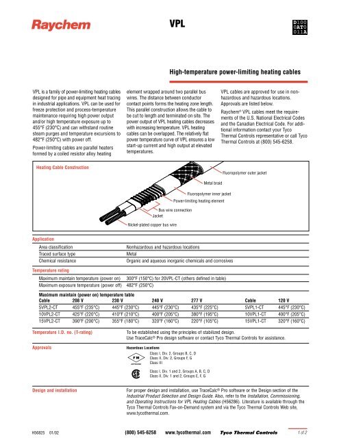
R VPL is a family of power-limiting heating cables designed for pipe and equipment heat tracing in industrial applications. VPL can be used for freeze protection and process-temperature maintenance requiring high power output and/or high temperature exposure up to 455°F (230°C) and can withstand routine steam purges and temperature excursions to 482°F (250°C) with power off. Power-limiting cables are parallel heaters formed by a coiled resistor alloy heating Heating Cable Construction VPL High-temperature power-limiting heating cables element wrapped around two parallel bus wires. The distance between conductor contact points forms the heating zone length. This parallel construction allows the cable to be cut to length and terminated on site. The power output of VPL heating cables decreases with increasing temperature. VPL heating cables can be overlapped. The relatively flat power temperature curve of VPL ensures a low start-up current and high output at elevated temperatures. Bus wire connection Jacket Nickel-plated copper bus wire Application Area classification Nonhazardous and hazardous locations Traced surface type Metal Chemical resistance Organic and aqueous inorganic chemicals and corrosives Temperature rating Maximum maintain temperature (power on) 300°F (150°C) for 20VPL-CT (others defined in table) Maximum exposure temperature (power off) 482°F (250°C) VPL cables are approved for use in nonhazardous and hazardous locations. Approvals are listed below. Raychem ® VPL cables meet the requirements of the U.S. National Electrical Codes and the Canadian Electrical Code. For additional information contact your Tyco Thermal Controls representative or call Tyco Thermal Controls at (800) 545-6258. Maximum maintain (power on) temperature table Cable 208 V 230 V 240 V 277 V Cable 120 V 5VPL2-CT 455°F (235°C) 445°F (230°C) 445°F (230°C) 435°F (225°C) 5VPL1-CT 445°F (230°C) 10VPL2-CT 425°F (220°C) 410°F (210°C) 400°F (205°C) 380°F (195°C) 10VPL1-CT 400°F (205°C) 15VPL2-CT 390°F (200°C) 355°F (180°C) 320°F (160°C) 220°F (105°C) 15VPL1-CT 320°F (160°C) Temperature I.D. no. (T-rating) To be established using the principles of stabilized design. Use TraceCalc ® Pro design software or contact Tyco Thermal Controls for assistance. Approvals Hazardous Locations Class I, Div. 2, Groups B, C, D Class II, Div. 2, Groups F, G Class III Fluoropolymer inner jacket Class I, Div. 1 and 2, Groups A, B, C, D Class II, Div. 1 and 2, Groups E, F, G Metal braid Power-limiting heating element Fluoropolymer outer jacket Design and installation For proper design and installation, use TraceCalc ® Pro software or the Design section of the Industrial Product Selection and Design Guide. Also, refer to the Installation, Commissioning, and Operating Instructions for VPL Heating Cables (H56286). Literature is available through the Tyco Thermal Controls Fax-on-Demand system and via the Tyco Thermal Controls Web site, www.tycothermal.com. H56825 01/02 (800) 545-6258 www.tycothermal.com Tyco Thermal Controls 1of 2
R<br />
<strong>VPL</strong> is a family of power-limiting heating cables<br />
designed for pipe and equipment heat tracing<br />
in industrial applications. <strong>VPL</strong> can be used for<br />
freeze protection and process-temperature<br />
maintenance requiring high power output<br />
and/or high temperature exposure up to<br />
455°F (230°C) and can withstand routine<br />
steam purges and temperature excursions to<br />
482°F (250°C) with power off.<br />
Power-limiting cables are parallel heaters<br />
formed by a coiled resistor alloy heating<br />
Heating Cable Construction<br />
<strong>VPL</strong><br />
High-temperature power-limiting heating cables<br />
element wrapped around two parallel bus<br />
wires. The distance between conductor<br />
contact points forms the heating zone length.<br />
This parallel construction allows the cable to<br />
be cut to length and terminated on site. The<br />
power output of <strong>VPL</strong> heating cables decreases<br />
with increasing temperature. <strong>VPL</strong> heating<br />
cables can be overlapped. The relatively flat<br />
power temperature curve of <strong>VPL</strong> ensures a low<br />
start-up current and high output at elevated<br />
temperatures.<br />
Bus wire connection<br />
Jacket<br />
Nickel-plated copper bus wire<br />
Application<br />
Area classification Nonhazardous and hazardous locations<br />
Traced surface type Metal<br />
Chemical resistance Organic and aqueous inorganic chemicals and corrosives<br />
Temperature rating<br />
Maximum maintain temperature (power on) 300°F (150°C) for 20<strong>VPL</strong>-CT (others defined in table)<br />
Maximum exposure temperature (power off) 482°F (250°C)<br />
<strong>VPL</strong> cables are approved for use in nonhazardous<br />
and hazardous locations.<br />
Approvals are listed below.<br />
Raychem ® <strong>VPL</strong> cables meet the requirements<br />
of the U.S. National Electrical Codes<br />
and the Canadian Electrical Code. For additional<br />
information contact your <strong>Tyco</strong><br />
<strong>Thermal</strong> <strong>Controls</strong> representative or call <strong>Tyco</strong><br />
<strong>Thermal</strong> <strong>Controls</strong> at (800) 545-6258.<br />
Maximum maintain (power on) temperature table<br />
Cable 208 V 230 V 240 V 277 V Cable 120 V<br />
5<strong>VPL</strong>2-CT 455°F (235°C) 445°F (230°C) 445°F (230°C) 435°F (225°C) 5<strong>VPL</strong>1-CT 445°F (230°C)<br />
10<strong>VPL</strong>2-CT 425°F (220°C) 410°F (210°C) 400°F (205°C) 380°F (195°C) 10<strong>VPL</strong>1-CT 400°F (205°C)<br />
15<strong>VPL</strong>2-CT 390°F (200°C) 355°F (180°C) 320°F (160°C) 220°F (105°C) 15<strong>VPL</strong>1-CT 320°F (160°C)<br />
Temperature I.D. no. (T-rating) To be established using the principles of stabilized design.<br />
Use TraceCalc ® Pro design software or contact <strong>Tyco</strong> <strong>Thermal</strong> <strong>Controls</strong> for assistance.<br />
Approvals Hazardous Locations<br />
Class I, Div. 2, Groups B, C, D<br />
Class II, Div. 2, Groups F, G<br />
Class III<br />
Fluoropolymer inner jacket<br />
Class I, Div. 1 and 2, Groups A, B, C, D<br />
Class II, Div. 1 and 2, Groups E, F, G<br />
Metal braid<br />
Power-limiting heating element<br />
Fluoropolymer outer jacket<br />
Design and installation For proper design and installation, use TraceCalc ® Pro software or the Design section of the<br />
Industrial Product Selection and Design Guide. Also, refer to the Installation, Commissioning,<br />
and Operating Instructions for <strong>VPL</strong> Heating Cables (H56286). Literature is available through the<br />
<strong>Tyco</strong> <strong>Thermal</strong> <strong>Controls</strong> Fax-on-Demand system and via the <strong>Tyco</strong> <strong>Thermal</strong> <strong>Controls</strong> Web site,<br />
www.tycothermal.com.<br />
<strong>H56825</strong> 01/02 (800) 545-6258 www.tycothermal.com <strong>Tyco</strong> <strong>Thermal</strong> <strong>Controls</strong><br />
1of 2
Nominal power output rating on metal pipes at 120 V and 240 V<br />
Adjustment factors<br />
Power output Circuit length<br />
208 V<br />
5<strong>VPL</strong>2-CT 0.77 0.89<br />
10<strong>VPL</strong>2-CT 0.78 0.90<br />
15<strong>VPL</strong>2-CT 0.79 0.91<br />
20<strong>VPL</strong>2-CT 0.80 0.92<br />
277 V<br />
5<strong>VPL</strong>2-CT 1.30 1.13<br />
10<strong>VPL</strong>2-CT 1.28 1.11<br />
15<strong>VPL</strong>2-CT 1.26 1.09<br />
20<strong>VPL</strong>2-CT not allowed<br />
A<br />
B<br />
C<br />
To choose the correct heating cable for your application use the Design section in the Industrial Product Selection and Design Guide.<br />
For more detailed information, use TraceCalc Pro design software.<br />
Maximum Circuit Length Based on Circuit Breaker Sizes<br />
D<br />
20<strong>VPL</strong><br />
15<strong>VPL</strong><br />
10<strong>VPL</strong><br />
5<strong>VPL</strong><br />
100 150<br />
(38) (66)<br />
Pipe temperature<br />
Ambient<br />
temperature<br />
Maximum continuous circuit length (in feet) per circuit breaker<br />
120 V 240 V<br />
at startup 15 A 20 A 30 A 40 A 50 A 15 A 20 A 30 A 40 A 50 A<br />
5<strong>VPL</strong>-CT 50°F (10°C) 260 350 370 — — 525 685 740 — —<br />
0°F (–18°C) 240 325 370 — — 485 645 740 — —<br />
–20°F (–29°C) 235 315 370 — — 470 625 740 — —<br />
–40°F (–40°C) 225 305 370 — — 455 610 740 — —<br />
10<strong>VPL</strong>-CT 50°F (10°C) 130 175 260 — — 260 350 525 — —<br />
0°F (–18°C) 120 165 245 260 — 245 325 490 525 —<br />
–20°F (–29°C) 120 160 240 260 — 235 315 475 525 —<br />
–40°F (–40°C) 115 155 230 260 — 230 310 465 525 —<br />
15<strong>VPL</strong>-CT 50°F (10°C) 85 115 175 215 — 175 230 350 430 —<br />
0°F (–18°C) 80 110 165 215 — 165 220 325 430 —<br />
–20°F (–29°C) 80 105 160 215 — 160 215 320 425 430<br />
–40°F (–40°C) 75 100 155 210 215 155 210 310 415 430<br />
20<strong>VPL</strong>-CT 50°F (10°C) 65 85 130 175 185 130 175 260 350 370<br />
0°F (–18°C) 60 85 125 165 185 125 165 250 330 370<br />
–20°F (–29°C) 60 80 120 160 185 120 160 245 325 370<br />
–40°F (–40°C) 60 80 120 160 185 115 155 240 320 370<br />
Note: <strong>Tyco</strong> <strong>Thermal</strong> <strong>Controls</strong> and national electrical codes require both ground-fault protection of equipment and a grounded metallic covering on all heating<br />
cables. Following are some of the ground-fault breakers that satisfy this equipment protection requirement: Square D Type QOB-EPD or QO-EPD;<br />
Raychem/Square D; Cutler Hammer (Westinghouse) Type QBGFEP.<br />
Product Characteristics 5<strong>VPL</strong>1-CT 5<strong>VPL</strong>2-CT<br />
10<strong>VPL</strong>1-CT 10<strong>VPL</strong>2-CT<br />
15<strong>VPL</strong>1-CT 15<strong>VPL</strong>2-CT<br />
20<strong>VPL</strong>1-CT 20<strong>VPL</strong>2-CT<br />
Minimum bend radius 3/4 in 3/4 in<br />
Supply voltage 100–120 Vac 200–277 Vac (20<strong>VPL</strong>2-CT 200–240 Vac only)<br />
Bus wire size 12 AWG 12 AWG<br />
Outer jacket color Red Red<br />
Weight (lb per 10 ft, nominal) 1.4 1.4<br />
Dimensions 0.46 x 0.31 in 0.46 x 0.31 in<br />
(W/ft)<br />
D<br />
5<br />
Components <strong>Tyco</strong> <strong>Thermal</strong> <strong>Controls</strong> offers a full range of components for power connections, splices and end<br />
seals. These components must be used to ensure proper functioning of the product and compliance<br />
with warranty, code, and approvals requirements.<br />
<strong>H56825</strong> 01/02 (800) 545-6258 www.tycothermal.com <strong>Tyco</strong> <strong>Thermal</strong> <strong>Controls</strong><br />
25<br />
20<br />
15<br />
10<br />
0<br />
A<br />
B<br />
C<br />
50<br />
(10)<br />
200<br />
(93)<br />
250<br />
(121)<br />
300 °F<br />
(149) (°C)<br />
<strong>VPL</strong><br />
2of 2


