Electro-Pneumatic Positioner TZIDC - Flowtec Industrietechnik GmbH.
Electro-Pneumatic Positioner TZIDC - Flowtec Industrietechnik GmbH. Electro-Pneumatic Positioner TZIDC - Flowtec Industrietechnik GmbH.
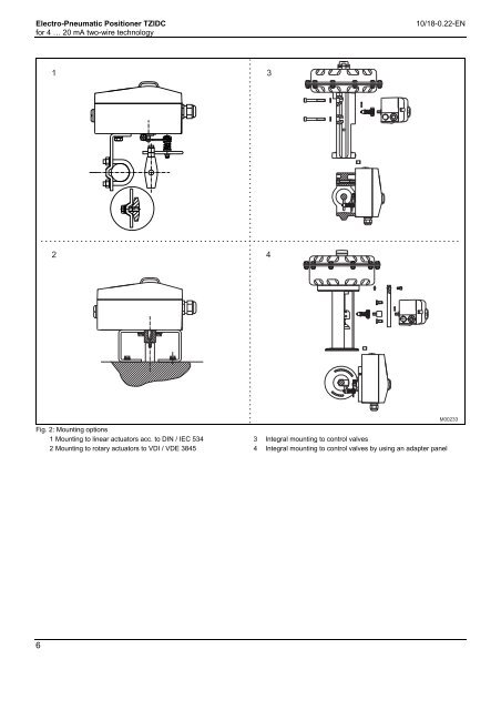
Electro-Pneumatic Positioner TZIDC 10/18-0.22-EN for 4 … 20 mA two-wire technology Pos: 5.14 /Technische Daten / Datenblatt/Aktorik/Stellungsregler/Allgemein/Montage/Anbauvarianten TZIDC-1x0 @ 10\mod_1173187335173_3101.doc @ 71286 @ 1 2 Fig. 2: Mounting options 1 Mounting to linear actuators acc. to DIN / IEC 534 2 Mounting to rotary actuators to VDI / VDE 3845 Pos: 6 /======= Seitenumbruch ======== @ 0\mod_1126532365768_3101.doc @ 3830 @ 6 3 4 3 Integral mounting to control valves 4 Integral mounting to control valves by using an adapter panel M00233
Electro-Pneumatic Positioner TZIDC 10/18-0.22-EN for 4 … 20 mA two-wire technology Pos: 7.1 /Überschriften/1/A - C/Betrieb @ 10\mod_1175678278921_3101.doc @ 76015 @ 11 3 Operation P os: 7.2 /==== Wechsel ein- auf zweispaltig ==== @ 0\mod_1130421847171_3101.doc @ 3828 @ Change from one to two columns Pos: 7.3 /Überschriften/1.1/2-spaltig/A - C/Allgemeines @ 10\mod_1176213970765_3101.doc @ 77124 @ 22 A 3.1 General P os: 7.4 /Technische Daten / Datenblatt/Aktorik/Stellungsregler/Allgemein/Betrieb/Allgemeines @ 10\mod_1176214294328_3101.doc @ 77292 @ Microprocessor-based position control in the TZIDC provides for optimal results. The positioner features high-precision control functions and high operational reliability. Due to their elaborate structure and easy accessibility, the device parameters can be quickly adapted to the respective application. Digital input For the digital input, one of the following safety options can be selected. You may use the operator’s panel or configuration program to select an option. - No function (default) - Move to 0 % position - Move to 100 % position The total range of parameters includes: - Hold previous position - Operating parameters - disable local configuration - Adjustment parameters - Disable local configuration and operation - Monitoring parameters - Disable any access (no local or remote access via a PC) - Diagnosis parameters The selected function is activated once the 24 V DC signal is no - Maintenance parameters longer applied (< 11 V DC). Pos: 7.5 /Überschriften/1.1.1/2-spaltig/Betriebsparameter @ 10\mod_1176214001500_3101.doc @ 77145 @ 33 3.1.1 Operating parameters Pos: P os: 7.6 /Technische Daten / Datenblatt/Aktorik/Stellungsregler/TZIDC / TZIDC-200/Betrieb/Betriebsparameter @ 10\mod_1176214346265_3101.doc @ 77343 @ The following operating parameters can be set manually if required: Pos: 7.7 /Überschriften/1.1.1/2-spaltig/Justageparameter @ 10\mod_1176214036515_3101.doc @ 77166 @ 33 3.1.2 Adjustment parameters 7.8 /Technische Daten / Datenblatt/Aktorik/Stellungsregler/TZIDC / TZIDC-200/Betrieb/Justageparameter @ 17\mod_1202462076828_3101.doc @ 156313 @ The TZIDC positioner has a special function for automatic adjustment of the parameters. Additionally, the control parameters can be set automatically (in adaptive control mode) or manually to optimally adapt them to the process requirements. Signal Signal min. 4 mA, max. signal 20 mA (0 ... 100 %) freely selectable for split-range operation min. range 20 % (3.2 mA) recommended range > 50 % (8.0 mA) Tolerance band Upon reaching the tolerance band, the position is slowly re-adjusted Action (positioning signal) until the dead band has been reached. Increasing: Signal 4 ... 20 mA = position 0 ... 100 % Increasing: Signal 20 ... 4 mA = position 0 ... 100 % Dead band (sensitivity) When reaching the dead band, the position is held. The factory Characteristic curve (travel = f {signal}) Linear, equal percentage 1:25 or 1:50 or 25:1 or 50:1 or freely setting for this parameter is 0,1 %. configurable with 20 reference points. Actuator spring action Travel limit The positioning travel, i.e. the stroke or angle of rotation, can be reduced as required within the full range of 0 ... 100 %, provided that a minimum value of 20 % is observed. Selection of the sensor shaft rotating sense (looking into the open case), if the valve is moved to the safe position by the actuator spring (actuator is depressurized via Y1 / OUT1). For double-acting actuators the actuator spring action corresponds to pressurizing the pneumatic output (OUT2). Shut-off function This parameter can be set separately for each end position. When the respective configured limit value is exceeded, the shut-off function causes immediate travel of the actuator until reaching the set Display 0 ... 100 % Adjusting the display (0 ... 100%) according to the direction of action for opening or closing the valve. end position. Pos: 7.9 /Überschriften/1.1.1/2-spaltig/Betriebsüberwachungsparameter @ 10\mod_1176214071453_3101.doc @ 77187 @ 33 When the shut-off value is set to “0”, the position is further controlled, even in the respective end position. 3.1.3 Monitoring parameters / / Pos: 7.10 /Technische Daten Datenblatt/Aktorik/Stellungsregler/TZIDC TZIDC-200/Betrieb/Betriebsüberwachungsparameter @ 10\mod_1176214447375_3101.doc @ 77385 @ B Various functions for permanent operational monitoring are implemented in the TZIDC operating program. The following states Travel time prolongation This function can be used to increase the max. travel time for full will be detected and indicated, e.g.: travel. This time parameter can be set separately for each direction. - 4 ... 20 mA signal out of range Important - position out of the adjusted range This function can only be used with the pneumatics with the - positioning time-out (adjustable time parameter) safety function “fail-safe”. - position controller inactive Switching points for the position This parameter allows you to define two position limits for signaling (see option “Module for digital position feedback”). - counter limits (settable in the diagnosis phase) exceeded While automatic commissioning is in progress, the current state is continuously indicated on the integrated LCD. During operation, the LCD shows the most important process Digital output variables: The alarms generated in the TZIDC positioner can be polled via the - current position (in %), digital output as a collective alarm. - malfunctions, alarms, messages (as code) The desired information can be selected via the operator panel or remotely via the configuration program. The output can be set to “active high” or “active low”, as required. Access to extended monitoring parameters is possible via HART communication and the DTM. Pos: 7.11 /======= Seitenumbruch ======== @ 0\mod_1126532365768_3101.doc @ 3830 @ 7
- Page 1 and 2: Data Sheet 10/18-0.22-EN Pos: 1 /Ti
- Page 3 and 4: Electro-Pneumatic Positioner TZIDC
- Page 5: Electro-Pneumatic Positioner TZIDC
- Page 9 and 10: Electro-Pneumatic Positioner TZIDC
- Page 11 and 12: Electro-Pneumatic Positioner TZIDC
- Page 13 and 14: Electro-Pneumatic Positioner TZIDC
- Page 15 and 16: Electro-Pneumatic Positioner TZIDC
- Page 17 and 18: Electro-Pneumatic Positioner TZIDC
- Page 19 and 20: Electro-Pneumatic Positioner TZIDC
- Page 21 and 22: Electro-Pneumatic Positioner TZIDC
- Page 24: ABB has Sales & Customer Support ex
<strong>Electro</strong>-<strong>Pneumatic</strong> <strong>Positioner</strong> <strong>TZIDC</strong> 10/18-0.22-EN<br />
for 4 … 20 mA two-wire technology<br />
Pos: 5.14 /Technische Daten / Datenblatt/Aktorik/Stellungsregler/Allgemein/Montage/Anbauvarianten <strong>TZIDC</strong>-1x0 @ 10\mod_1173187335173_3101.doc @ 71286 @<br />
1<br />
2<br />
Fig. 2: Mounting options<br />
1 Mounting to linear actuators acc. to DIN / IEC 534<br />
2 Mounting to rotary actuators to VDI / VDE 3845<br />
Pos:<br />
6 /======= Seitenumbruch ======== @ 0\mod_1126532365768_3101.doc @ 3830 @<br />
6<br />
3<br />
4<br />
3 Integral mounting to control valves<br />
4 Integral mounting to control valves by using an adapter panel<br />
M00233


