ZE-Series, Specifications & Dimensions <strong>Hydraulic</strong> Technology Worldwide Oil Flow (l/min) � 4 3 3 94 6 163 14 12 10 8 6 4 2 Pump Series Two-stage Single-stage 14 0 0 140 280 420 560 700 0 0 140 280 420 560 700 0 0 140 280 420 560 700 0 0 140 280 420 560 700 Pressure (bar) � Pressure (bar) � Pressure (bar) � Pressure (bar) � 2 640 C 414 483 635 710 C 447 65 2 4 8 ZE3 � ZE-SERIES PERFORMANCE CHART ZE3 ZE4 ZE5 ZE6 at 7 bar Output Flow Rate at 50 Hz * (l/min) low pressure high pressure 0,59 6,15 0,87 8,88 1,75 11,61 3,00 12,29 at 50 bar 0,59 5,26 0,87 8,20 1,72 11,27 2,94 12,15 at 350 bar 0,57 0,57 0,84 0,84 1,68 1,68 2,86 2,86 132 Oil Flow (l/min) � 12 10 8 6 4 2 at 700 bar 0,55 0,55 0,82 0,82 1,64 1,64 2,73 2,73 640 ZE-Series Pumps with 4 - 8 litres reservoir Pump Unit Single-stage Two-stage Single-stage Two-stage Single-stage Two-stage Single-stage Two-stage * Oil flow will be approximately 6/5 of these values at 60 Hz. ZE-Series Pumps with 10 - 20 - 40 litres reservoir 7 330 D 240 267 E1 B A D E 14 14 ZE4 12 ZE5 12 ZE6 1 B 1 5 B Oil Flow (l/min) � A H A H 10 8 6 4 2 Available Reservoir Sizes (useable oil) (litres) 4-8-10-20-40 4-8-10-20-40 10-20-40 10-20-40 Motor Size (kW) 0,75 1,12 2,24 5,60 Relief Valve Adjustment Range (bar) 70-700 70-700 70-700 70-700 10 8 6 4 2 � User adjustable relief valve on <strong>all</strong> manual and solenoid valves. 3/8” NPTF on A and B ports; 1/4”NPTF on auxiliary ports. � Electric Box � Heat Exchanger � Roll Bar � Return Line Filter � Skid Bar � Oil Drain � Oil Drain / Oil Level/Temperature Switch Reservoir Size (useable oil) 4(litres) 8 10 20 40 Sound Level (dBA) 75 75 75 80 A 457 519 533 558 648 Oil Flow (l/min) � Single or Two-Stage Choose single-stage pumps <strong>for</strong> applications that require constant flow regardless of pressure such as testing or clamping. Two-stage pumps have an increased output flow at low pressure to <strong>all</strong>ow fast movement towards the load, <strong>for</strong> reduced cycle times and increased productivity. ZE-Series Pump Dimensions (mm) B 143 205 155 180 270 C 279 287 419 419 399 D 152 168 305 422 505 E – – 384 501 576 E1 – – 340 490 572 www.enerpac.com H 520 582 600 625 715
� This is how ZE-Series pump model numbers are built up: Z 1 Product Type E 2 Motor Type 3 Flow Group 1 Product Type Z = Pump Class www.enerpac.com 4 1 10 D W- F H L T 4 Valve Type 5 Reservoir Size 2 Prime Mover E = Induction electric motor 3 Flow Group 3 = 0,55 l/min @ 700 bar (0,75 kW) 4 = 0,82 l/min @ 700 bar (1,12 kW) 5 1) = 1,64 l/min @ 700 bar (2,24 kW) 6 1) = 2,73 l/min @ 700 bar (5,60 kW) 6 Valve Operation 7 Motor Voltage ZE-Series, Pump Ordering Matrix 8 Factory inst<strong>all</strong>ed options 6 Valve Operation D = Dump valve (solenoid), with pendant and Electric Box L = Manual valve, without pendant, with Electric Box M = Manual valve, without pendant, without Electric Box N = No valve, without Electric Box S = Solenoid valve, with pendant and Electric Box W = No valve, with Electric Box, without pendant 10) 4 Valve Type 0 = No valve, with coverplate 1 = 3/2 Dump valve VE32D 2 = 3/2 manual VM32 3 = 3/3 manual VM33 or electric VE33 4 = 4/3 manual VM43 or 6 8 electric VE43 = 3/3 manual locking valve VM33L with pilot operated check. = 4/3 manual locking valve VM43L with pilot operated check. 5 Reservoir Size, useable oil 04 2) = 4 litres 08 2) 7 Motor Voltage Single phase motor = 8 litres 10 = 10 litres 20 = 20 litres 40 = 40 litres 3) B 3) = 115V, 1 ph, 50-60Hz E 3) = 208-240V, 1 ph, 50-60 Hz 4) I 3) = 208-240V, 1 ph, 50-60 Hz (with USA plug). Three phase motor 5) M 5) = 190-200V, 3 ph, 50-60Hz G 5) = 208-240V, 3 ph, 50-60 Hz W 5) = 380-415V, 3 ph, 50-60 Hz K 5) = 440V, 3 ph, 50-60 Hz J 5) R = 460-480V, 3 ph, 50-60 Hz 5) = 575V, 3 ph, 60 Hz 8 Factory inst<strong>all</strong>ed options F = Return Line Filter G 6) = 1000 bar gauge H 7) = Heat exchanger K = Skid Bar (only on 4-8 litres) L 7) = Oil Level/Temperature Switch 8) N = No reservoir handles (includes lifting eyes) P 7) = Pressure Switch (only available on manual valves without locking feature) R = Roll Bar S = Single-stage pump unit T 7) = Pressure transducer 9) U 7) = Foot Switch 1) ZE5 and ZE6-Series only available with 3-phase electric motors. 2) 4 and 8 litres only available on ZE3 and ZE4-Series. 3) ZE3 and ZE4-Series only available with 1-phase motors. 4) 208-240V, 1 ph with European plug EMV directive compliant. 5) Models with 3-ph motors without Electric Box shipped without cord, motor starter or overload protection. 6) Not available on pumps with pressure transducer (T). 7) Requires Electric Box. 8) Not available on 4 and 8 litres reservoir. 9) Provides digital pressure read-out on LCD-display of electric box. 10) When using solenoid valve on valve type “W” order optional pendant. All Z-Class electric pumps comply with CSA and CE requirements. ZE Series Reservoir Capacity: 4 - 40 litres Flow at Rated Pressure: 0,55 - 2,73 l/min Motor Size: 0,75 - 5,60 kW Maximum Operating Pressure: 700 bar How to Order Single-Stage Pumps To specify a single-stage pump, place the letter “S” at the end of the model number. For example: ZE4210ME-S ZE4-Series pump, oil flow 0,82 l/min at 700 bar, VM32 manual valve, 10 litres reservoir, without electrical box, without pendant, 240 Volt 1-phase electric motor and single-stage pump unit. ZE3120DW-S ZE3-Series pump, oil flow 0,55 l/min at 700 bar, VE32D solenoid dump valve, 20 litres reservoir, with electrical box, without pendant, 400 Volt 3-phase electric motor and single-stage pump unit. Pendants When ordering Enerpac VE- Series solenoid valve <strong>for</strong> use on “W” type valve operation (No Valve, with Electric Box, without pendant) the pendant must be ordered separately. Pendant connection to be plugged into electric box. Page: 93 95
- Page 1 and 2:
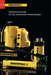
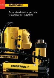
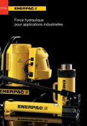
E325e Hydraulic Power for all Indus
- Page 3 and 4:
Model Number Index Section Index
- Page 5 and 6:
Class Brand 10 Good Reasons to Work
- Page 7 and 8:
Capacity 1) ton (kN) 5-95 (45-933)
- Page 9 and 10:
Think Safety Manufacturer’s ratin
- Page 11 and 12:
Speed Chart See the Enerpac Cylinde
- Page 13 and 14:
� From left to right: RAC-5010, R
- Page 15 and 16:
Optional Bolt On Tilt Saddle Dimens
- Page 17 and 18:
Optional Bolt On Tilt Saddle Dimens
- Page 19 and 20:
Aluminium versus Steel Aluminium cy
- Page 21 and 22:
Optional Bolt On Tilt Saddle Dimens
- Page 23 and 24:
H S 3/8"- 18NPTF Collapsed Height A
- Page 25 and 26:
Pump and Cylinder Sets All cylinder
- Page 27 and 28:
3 /4" - 14 NPT 11 /4"-111 1 /2 NPT
- Page 29 and 30:
Hoses Enerpac offers a complete lin
- Page 31 and 32:
Hoses Enerpac offers a complete lin
- Page 33 and 34:
� BRD CYLINDER ATTACHMENTS C D E
- Page 35 and 36:
Cylinder retract capacity for certa
- Page 37 and 38:
Cyl. Bore Dia. E (mm) 42,9 42,9 73,
- Page 39 and 40:
� QUICK SELECTION CHART For compl
- Page 41 and 42:
K1 J1 0-5˚ 41 Single-Acting, High
- Page 43 and 44: � QUICK SELECTION CHART For compl
- Page 45 and 46: K1 J1 0-5˚ 45 Single-Acting, High
- Page 47 and 48: RR-series For loads below 50 ton En
- Page 49 and 50: K1 J1 0-5˚ 49 Double-Acting, High
- Page 51 and 52: � QUICK SELECTION CHART For compl
- Page 53 and 54: Optional Tilt Saddle * Capacity: K1
- Page 55 and 56: Typical layout for a 4 points synch
- Page 57 and 58: � This 55 meters long absorber wa
- Page 59 and 60: Enerpac synchoist systems SyncHoist
- Page 61 and 62: � Shown from left to right: EBJ-4
- Page 63 and 64: 3/8"- 18NPTF RC-Series J 22 51 A 10
- Page 65 and 66: SET SELECTION: � 1 � 2 � 3
- Page 67 and 68: Power Source Manual Electric Air Ga
- Page 69 and 70: Pump and Cylinder sets All Pumps ma
- Page 71 and 72: High Temperature and Corrosion Resi
- Page 73 and 74: P-18 L M N 90˚ E P-25, P-50 M P-51
- Page 75 and 76: � Shown: P-392FP • Robust, dura
- Page 77 and 78: � Optional Ultra-High Pressure Fi
- Page 79 and 80: About the Economy Pump The Economy
- Page 81 and 82: Submerged Pump Application The Subm
- Page 83 and 84: CUSTOM BUILD YOUR SUBMERGED PUMP If
- Page 85 and 86: 14 12 10 8 6 4 2 ZU4 & ZE-Series, P
- Page 87 and 88: ZU4-Series Pump Applications The ZU
- Page 89 and 90: ZU4-Series with 4 and 8 litres rese
- Page 91 and 92: • High-efficiency pump design - h
- Page 93: Factory Options & Accessory Kits fo
- Page 97 and 98: 1030 790 40 Used with Cylinder* -
- Page 99 and 100: PATG-models use a foot or hand oper
- Page 101 and 102: � Shown: PAM-1041 • Twin air mo
- Page 103 and 104: H � This is how a ZA4-Series pump
- Page 105 and 106: All PAH-Series air hydraulic pumps
- Page 107 and 108: Atlas Gasoline Pump Performance Ele
- Page 109 and 110: ? i Enerpac ‘Yellow Pages’ stan
- Page 111 and 112: ; y ; y General ✓ � Always read
- Page 113 and 114: � Complete the following informat
- Page 115 and 116: Two point lifting set-up using sing
- Page 117 and 118: Force The amount of force a hydraul
- Page 119 and 120: Cylinder Speed This chart will help
- Page 121 and 122: C ENERPAC System Components: All th
- Page 123 and 124: Internal Diameter (mm) 6,4 9,7 Hose
- Page 125 and 126: C-604 F-604 T-630 E C E C E C A-604
- Page 127 and 128: Recommended Tubing Enerpac does not
- Page 129 and 130: Maximum Indicator Pointer Indicator
- Page 131 and 132: D Size 63 63 100 100 A C B Connecti
- Page 133 and 134: � Shown: DGR-1 • Two modes - Au
- Page 135 and 136: B ENERPAC hydraulic valves are avai
- Page 137 and 138: 1/4"-18NPTF 2 89 VM32 1 130 P T P T
- Page 139 and 140: GP 1/4"- 2 18NPTF VM43, VM43L 1) fo
- Page 141 and 142: Premounted Manifolds For two or fou
- Page 143 and 144: A K H P O A G J D Available in capa
- Page 145 and 146:
H K H N Press Capacity K O P N H K
- Page 147 and 148:
� An BPR-20075 Roll-Frame Press i
- Page 149 and 150:
� A perfect example of the force
- Page 151 and 152:
� Shown: LH-102 and TM-5 (in midd
- Page 153 and 154:
When selecting a puller it is impor
- Page 155 and 156:
� Shown: Grip Puller Set BHP-351G
- Page 157 and 158:
� Shown: BHP-380 � SELECTION CH
- Page 159 and 160:
Posi Lock ® Pullers � QUICK SELE
- Page 161 and 162:
Length (mm) 25 50 31 50 31 50 50 Sp
- Page 163 and 164:
B � SETS SELECTION CHART D Style
- Page 165 and 166:
� EPH-1003E • Roller cart with
- Page 167 and 168:
Capacity ton (kN) 2,5-12,5 (22 -116
- Page 169 and 170:
CAUTION! max. When cylinders are 50
- Page 171 and 172:
■7 Threaded Plunger Toe ton Model
- Page 173 and 174:
� QUICK SELECTION CHART 50 ; 16
- Page 175 and 176:
�Shown: SOH-10-6 • For lifting
- Page 177 and 178:
B C F E D A C E B D A F B A D C B A
- Page 179 and 180:
�Shown from top to bottom: WR-15,
- Page 181 and 182:
�Shown from left to right: WMC-20
- Page 183 and 184:
STB-202 One Shot Sweep Bending Bend
- Page 185 and 186:
Mono-Strand Tensioning Tool Operati
- Page 187 and 188:
Capacity ton (kN) 5 - 90 (45 -801)
- Page 189 and 190:
� Shown: FS-56 • Lightweight, e
- Page 191 and 192:
Hydraulic and Mechanical General Fl
- Page 193 and 194:
Torque Range (Nm) � 7 /8 15 /8 35
- Page 195 and 196:
Optional Allen-Key Drives and React
- Page 197 and 198:
Torque Range (Nm) � 27.500 25.000
- Page 199 and 200:
� SELECTION CHART TORQUE WRENCH M
- Page 201 and 202:
Torque Range (Nm) � 22.000 20.000
- Page 203 and 204:
H G � SELECTION CHART Drive Unit
- Page 205 and 206:
� Torque Range (Nm) � 24.000 22
- Page 207 and 208:
The optional Reducer Insert � mus
- Page 209 and 210:
ELECTRIC PUMPS Flow at rated pressu
- Page 211 and 212:
� PTE-3404W • Two stage pump wi
- Page 213 and 214:
ZU4T-Series Pump Applications The Z
- Page 215 and 216:
(kW) 181 7 bar Reservoir Size (usea
- Page 217 and 218:
� PMA-62480 • High-output air d
- Page 219 and 220:
www.enerpac.com for latest Enerpac
- Page 221 and 222:
▼ Millau Viaduct, France - The wo
- Page 223 and 224:
Model Number Index � � Page(s)