
Create successful ePaper yourself
Turn your PDF publications into a flip-book with our unique Google optimized e-Paper software.
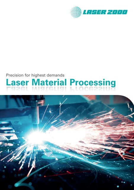
<strong>Laser</strong> <strong>Material</strong> <strong>Processing</strong><br />
Precision for highest demands<br />
<strong>Laser</strong> <strong>Material</strong> <strong>Processing</strong>
<strong>Laser</strong> Test & Measurement<br />
Network Systems<br />
<strong>Laser</strong> & Light Sources Scan & Motion Systems<br />
<strong>Laser</strong> <strong>Material</strong> <strong>Processing</strong><br />
<strong>Laser</strong> Safety<br />
Test & Measurement<br />
Fiber Preparation<br />
Fiber Optics Cameras<br />
Optics & Optomechanics<br />
Machine Vision<br />
Experts in Europe! <strong>Laser</strong> 2000 is headquartered in the metropolitan<br />
area of greater Munich. We are driven by global thinking and local action. To<br />
meet the individual market and customer needs we have subsidiaries and offices<br />
all across Europe. Our team also serves you from direct offices in Paris and<br />
Bordeaux, in Madrid, Gothenburg and Stockholm. Together with affiliated<br />
companies in Great Britain, Belgium and the Netherlands we insure international<br />
proximity to our customers.<br />
For more than 30 years, <strong>Laser</strong> 2000 supplies Photonics and FiberOptic solutions<br />
matching even the most demanding applications. We cooperate with global<br />
leaders to supply customer-specific solutions from a single source. Our passion<br />
for the fascinating world of photonics is the basis of our thinking and actions. We<br />
are avid promoters of optical technologies and are always on the cutting edge of<br />
development, products and application options.<br />
We rely on innovation, highest quality and in particular on the knowledge,<br />
creativity and enthusiasm of our employees. An excellent team of university<br />
educated physicists and engineers coupled with long experience consult you in<br />
selecting ideal solutions.<br />
General Contact:<br />
<strong>Laser</strong> 2000 GmbH | Argelsrieder Feld 14 | 82234 Wessling – Germany<br />
Phone +49 8153 405-0 | Fax +49 8153 405-33 | info@laser2000.de | www.laser2000.de<br />
2
Introduction<br />
Precision for highest demands<br />
Optical technologies play an important role worldwide.<br />
Quotes such as “The future is in the light” or “Light creates<br />
jobs” are not just empty words. The optical technologies are<br />
considered to be the pacemaker technologies for the modern<br />
industry and society. In the course of this, laser sources are<br />
assumed as one of the most important pillars of the optical<br />
technologies.<br />
While laser sources are already established in industrial production<br />
and already used routinely in many applications like<br />
welding, cutting and cladding, recent research activities<br />
show entirely new perspectives for the use of laser light.<br />
The fiber laser technology allows laser powers in the kW<br />
range generated in compact and modular systems. Cutting,<br />
welding and other applications in material processing can be<br />
done with fastest processing speed. Femtosecond lasers<br />
emit extremely short light pulses, which make it possible to<br />
cut or to process materials without any disturbing thermal<br />
effects.<br />
This catalog gives you an overview about our extensive portfolio<br />
of laser sources, optical and mechanical components and<br />
measurement equipment for applications in laser material<br />
processing.<br />
3
Chapter in detail<br />
<strong>Laser</strong> Sources<br />
Commercial High Power Fiber <strong>Laser</strong>s.................................................................................... Page 6<br />
Ultra Short Pulse <strong>Laser</strong>s........................................................................................................... Page 8<br />
Industrial Excimer OEM <strong>Laser</strong>s – UV and DUV.................................................................... Page 10<br />
Diode <strong>Laser</strong> System for Surface Treatment......................................................................... Page 12<br />
<strong>Laser</strong> Beam Delivery<br />
Digital Galvanometer Scan Head (10 mm aperture size).................................................... Page 14<br />
Polygonal Scan Heads ........................................................................................................... Page 16<br />
Polygonal Scanners................................................................................................................ Page 17<br />
Polygonal Mirrors................................................................................................................... Page 18<br />
Resonant Scanners................................................................................................................. Page 19<br />
Optics....................................................................................................................................... Page 20<br />
Motion Systems – Hybrid Hexapods and Tripods............................................................... Page 24<br />
High Precision – X-, XY- and Z-Axes..................................................................................... Page 25<br />
Linear Stepper Motor Stages................................................................................................. Page 26<br />
Stepping Motor Rotation Stages........................................................................................... Page 27<br />
Simplified Motion Control...................................................................................................... Page 28<br />
Automated <strong>Laser</strong> Beam Alignment and Stabilization System........................................... Page 30<br />
Test & Measurement<br />
Real-time Profiling for Focusing, M 2 , Divergence & Alignment........................................ Page 32<br />
Inline <strong>Laser</strong> Welding quality assessment system............................................................... Page 34<br />
Probamus – Machine Vision with laser optics and scan head .......................................... Page 36<br />
Non-contact “Line” Sensors in the visible range................................................................ Page 38<br />
Vision System – Chromatic Confocal Microscope.............................................................. Page 40<br />
4
Technical Guidance and Sales Support<br />
Stephan Kennerknecht | Phone +49 8153 405-51 | s.kennerknecht@laser2000.de<br />
<strong>Laser</strong> Spares and Consumables<br />
<strong>Laser</strong> replacement parts........................................................................................................ Page 42<br />
<strong>Laser</strong> Safety<br />
Safety products for laser applications................................................................................. Page 43<br />
Custom Solutions<br />
Engineering your ideas!......................................................................................................... Page 46<br />
5
<strong>Laser</strong> Sources<br />
Commercial High Power Fiber <strong>Laser</strong>s<br />
The Corelight fiber laser turnkey systems and engines offer<br />
outstanding performance for demanding macro-material<br />
processing applications. Each Corelight system or engine incorporates<br />
one or more high-brightness 2.1 kW ytterbium fiber<br />
laser modules or 2.1 kW direct-diode laser modules.<br />
Building with high-power modules enables straightforward<br />
power scaling while maintaining the high optical brightness<br />
necessary for ultra-fast, precise material processing.<br />
Advantages<br />
• Compact ytterbium fiber lasers for straight forward<br />
integration into machine tools and turn-key fiber<br />
laser systems<br />
• High-power and high-brightness 2.1 kW modular<br />
building blocks with < 0.9 mm mrad BPP (typical)<br />
• Modulation up to 10 kHz<br />
6
Technical Guidance and Sales Support<br />
Gerold Simke | Phone +49 3594 7059-86 | g.simke@laser2000.de<br />
Applications<br />
• Sheet Metal Cutting<br />
High-speed cutting of thin and thick<br />
metals including highly reflective<br />
aluminum, copper and brass. Narrow<br />
heat affected zone and finish quality<br />
edges.<br />
• Welding<br />
Fast remote welding of continuous<br />
seams for lighter and stronger<br />
structures. Hybrid-welding for deep<br />
penetration and improved processing<br />
speeds.<br />
• Cladding/<strong>Material</strong> Deposition<br />
Surface preparation through deposition<br />
of hard materials for bearing<br />
surfaces.<br />
Technical details<br />
Model YLE 2100 YLE 4300 YLE 6300<br />
Power 2.1 kW 4.2 kW 6.3 kW<br />
Wavelength 1081 nm 1081 nm 1081 nm<br />
Modules 1 FL Module 2 FL Modules 3 FL Modules<br />
BPP < 3 mm-mrad < 3 mm-mrad < 3 mm-mrad<br />
Fiber connector incl. LLK-B incl. LLK-B incl. QBH Connector<br />
Weight 44 kg 110 kg 155 kg<br />
Specifications are subject to change without notice.<br />
7
<strong>Laser</strong> Sources<br />
Ultra Short Pulse <strong>Laser</strong>s<br />
Amplitude <strong>Laser</strong> Group is a leading manufacturer of ultrafast<br />
lasers for industrial, medical and scientific applications. Amplitude<br />
Systemes offers a new generation of all solid-state,<br />
diode-pumped femtosecond lasers. Direct benefits for the<br />
users are reduced size, improved reliability and lower cost,<br />
and unmatched optical performances. The products include<br />
oscillators, femtosecond and picosecond amplifiers, SHG/<br />
THG extensions, synchronization to external sources (synchrotrons)<br />
and optical parametrical amplifiers (OPAs).<br />
Advantages<br />
• Average power: 1 W - 100 W<br />
• Pulse energies: 50 nJ - 2 mJ<br />
• Pulse duration: 200 fs - 10 ps<br />
• Repetition rates: single shot to 2 MHz and beyond<br />
• 1030 nm, 515 nm, 343 nm<br />
• OPA with 210 - 11000 nm<br />
• Burst-mode option<br />
• Synchronization to external sources<br />
• Compact, industrial design<br />
• Fiber and crystal based technology<br />
• Air cooling<br />
8
Technical Guidance and Sales Support<br />
Mark Drechsler | Phone +49 8153 405-54 | m.drechsler@laser2000.de<br />
Adapted laser solutions for a wide range of applications<br />
s-Pulse – Medical devices manufacturing<br />
Satsuma – Semi-conductor<br />
Tangor – Micromachining<br />
t-Pulse – Ophthalmology<br />
Key Features<br />
Tangerine – Internal engraving<br />
Markets<br />
Mikan & Mango<br />
Biology & Spectroscopy<br />
• High flexibility in terms of power, energy, pulse duration,<br />
and wavelength<br />
Applications<br />
• Micromachining<br />
• Structuring and engraving<br />
• Dicing<br />
• Cutting<br />
• Drilling<br />
• 2 Photon Polymerization<br />
• Display industry<br />
• Ophthalmology<br />
• Medical device manufacturing<br />
• Watchmaking industry<br />
• Semiconductor industry<br />
• Bio-imaging<br />
• R&D<br />
• Science<br />
9
<strong>Laser</strong> Sources<br />
Industrial Excimer OEM <strong>Laser</strong>s – UV and DUV<br />
For years Excimer laser systems have been established in micromachining<br />
and various transparent material engraving.<br />
One of the most important challenges of Excimer lasers are<br />
the operation costs. <strong>Laser</strong> 2000 provides a novel Excimer laser<br />
concept reducing the operatin costs by 50 % compared to<br />
conventional Excimer lasers in the market.<br />
Of course a professional service for Excimer laser systems is<br />
extremely important. Therefore, <strong>Laser</strong> 2000 has extended<br />
their service capabilities. In addition to the full coverage service<br />
contracts individual maintenance agreements completes<br />
the <strong>Laser</strong> 2000 services.<br />
Key Features<br />
• Rigid Design<br />
• Corona Pre-Ionization<br />
• Solid-State circuitry<br />
• Tube Technology<br />
• Energy Monitor<br />
• Compact laser, single phase<br />
10
Technical Guidance and Sales Support<br />
Gerold Simke | Phone +49 3594 7059-86 | g.simke@laser2000.de<br />
Technical details<br />
Specifications ArF ArF ArF KrF KrF KrF<br />
Wavelength (nm) 193 193 193 248 248 248<br />
Max. Repetition Rate (Hz) 200 500 1000 200 500 1000<br />
Stabilized Pulse Energy (mJ) 6 6 6 10 10 10<br />
Stabilized Pulse Power (W) 1,2 3,0 6,0 2,0 5,0 10<br />
Energy Stability (sigma, %) 2 2 2 2 2 2<br />
Beam Dimensions (FWHM, V x H mm) 6 x 3 6 x 3 6 x 3 6 x 3 6 x 3 6 x 3<br />
Beam Divergence (FWHM, V x H mrad) 2 x 1 2 x 1 2 x 1 2 x 1 2 x 1 2 x 1<br />
Pulse Duration (FWHM) (ns) 5 - 10 5 - 10 5 - 10 5 - 15 5 - 15 5 - 15<br />
Weights/Dimensions<br />
Weight<br />
approx. 75 kg<br />
Cooling<br />
by air<br />
Electrical<br />
230 VAC, 50/60 Hz, 2 kW max.<br />
Dimensions<br />
560 mm x 315 mm x 445 mm<br />
* Specifications are subject to change without notice.<br />
Customer Benefits<br />
• High reliability<br />
• Homogenious beam profile<br />
• Immediate availability without aging<br />
• Metal sealed tubes<br />
• Extended lifetimes for many billion pulses<br />
• Energy stabilizing<br />
• Plug& play, easy system integration<br />
11
<strong>Laser</strong> Sources<br />
Diode <strong>Laser</strong> System for Surface Treatment<br />
High power semiconductor lasers have found increased applications<br />
in direct material processing applications such as<br />
welding, cutting, and surface treatment. Driven by low cost,<br />
longer lifetime and new applications, the requirements of<br />
high power semiconductor lasers have been changed and<br />
the demand for new products has been accelerated in recent<br />
years. As a result, high power semiconductor lasers have<br />
been highly developed and are now available as complete<br />
processing heads for high-end direct material processing applications.<br />
Advantages<br />
• Excellent surface quality<br />
• High processing speed<br />
• Small footprint<br />
• High electro-optical efficiency<br />
• High reliability<br />
• Easy to maintain<br />
• Robust protection & monitoring<br />
• > 50 % overall electro-optical efficiency<br />
12
Technical Guidance and Sales Support<br />
Dr. Daniel Kreier | Phone +49 8153 405-50 | d.kreier@laser2000.de<br />
Technical details<br />
Optical Parameters 1<br />
Units FL-DLight3-1500 FL-DLight3-4000 FL-DLight3-6000<br />
Operation Mode - CW CW CW<br />
Output Power 2 W 1500 4000 6000<br />
Power Stability % ≤ 1 ≤ 1 ≤ 1<br />
Wavelength nm 9xx 9xx&8xx 9xx&8xx<br />
Power Conversion Eff. % ≥ 50 ≥ 50 ≥ 50<br />
Working Distance mm 275 ± 10 300 ± 10 300 ± 10<br />
Beam Size mm 3 × 1 14 × 2 or 20 × 2 14 × 2 or 20 × 2<br />
Dimension mm 330 × 145 × 140 454 × 246 × 163 454 × 246 × 163<br />
Weight kg < 12 < 15 < 25<br />
Electrical Parameters 3<br />
Input Current A ~ 25 ~ 25 ~ 50<br />
Input Voltage V 380 380 380<br />
Max Operating Current A ~ 80 ~ 110 ~ 110<br />
Max Operating Voltage V ~ 40 ~ 75 ~ 150<br />
Ambient Parameters 4<br />
Operating Temperature °C 5 ~ 45 5 ~ 45 5 ~ 45<br />
Storage Temperature °C 0 ~ 65 0 ~ 65 0 ~ 65<br />
Refrigeration Mode - Water-cooling Water-cooling Water-cooling<br />
Optional<br />
Power Supply/Controller/Chilling System<br />
1<br />
Data at Operating temperature, unless otherwise stated.<br />
2<br />
Reduced lifetime if used above nominal operating conditions.<br />
3<br />
Electrical Parameters standard by test report.<br />
4<br />
A non-condensing environment is required for storage and operation below ambient dew point.<br />
Typical Applications<br />
• Metallurgy<br />
• Mould remanufacturing<br />
• Petrochemical machinery<br />
• Steel plant<br />
• Energy industry and power transmission<br />
13
<strong>Laser</strong> Beam Delivery<br />
Digital Galvanometer Scan Head (10 mm aperture size)<br />
The scan head DigiCube II is designed for 10 mm aperture<br />
size and equipped with digital self-tuning galvanometers.<br />
The housing is designed as OEM drop-in replacement for existing<br />
leading manufacturers. It has industry standard mechanical<br />
bolt patterns, compatible power and communication<br />
pinouts. As communication protocol the industry<br />
standard XY2-100 protocol can be used.<br />
Mirror coatings are available for the typical common laser<br />
wavelengths as standard (1,064 nm, 532 nm, 355 nm) and as<br />
custom solution for other wavelengths on request. The cost<br />
level is competitive to analog controlled scan heads but the<br />
performance superior due to the digital galvanometer technology.<br />
Key Features<br />
• Lowest costs<br />
• Digital self-tuning galvanometers<br />
• Highly dynamic<br />
• Drop-In replacement for comparable analogue<br />
scan heads<br />
14
Technical Guidance and Sales Support<br />
Gerold Simke | Phone +49 3594 7059-86 | g.simke@laser2000.de<br />
Technical details<br />
Power supply requirement<br />
+ 24 / - 24 V 4 A<br />
Maximum current drive to galvo<br />
10 A<br />
Quiescent power draw (no marking) < 10 W<br />
Positioning speed m/s 10 - 20<br />
Marking speed m/s 3 - 6<br />
Precision writing cps 500<br />
High quality writing cps 1000<br />
Resolution µrad<br />
10 µrad<br />
1 % step response setting to 0.1 % fs 0.28 ms<br />
Scale drift ppm/C < 40<br />
Zero drift µrad/C < 10<br />
Linearity 99.9 %<br />
Short term repeatability µrad < 8<br />
Dither RMS<br />
< 10 µrad<br />
Weight<br />
2.2 kg<br />
Dimensions<br />
A: 97 mm<br />
B: 115 mm<br />
C: 97 mm<br />
D: 15 mm<br />
E: 30 mm<br />
F: 90 mm<br />
Typical applications<br />
• High Accuracy <strong>Laser</strong> Marking<br />
• Scribing/Engraving<br />
• Welding<br />
• Photovoltaic Production<br />
• Trimming<br />
• Rapid Prototyping<br />
• On the Fly <strong>Processing</strong><br />
• <strong>Laser</strong> 3D Printing<br />
• Scanner Control Systems in medical equipment<br />
15
<strong>Laser</strong> Beam Delivery<br />
Polygonal Scan Heads<br />
The portfolio includes the housed polygons scanners and the<br />
combination of polygonal scanners and galvanometer mirrors<br />
as packaged scan head solution. Polygonal scan heads<br />
produce a line scan for highest possible scan speeds. The<br />
additional galvanometer mirrors can be used for line jumps<br />
or correction of the beam position while the polygonal scanner<br />
is constantly moving with highest speeds. The polygonal<br />
scanners can depending on the application be 100 times faster<br />
than pure galvanometer solutions. Printing and imaging<br />
applications as well as high-speed laser material ablation applications<br />
require high precision and always more and more<br />
speed. Own design and production of theses scanners, motors,<br />
bearings and electronics allow us to reach the high requirements<br />
for these modern applications.<br />
Advantages<br />
• Polygonal scan heads<br />
• Polygon/Galvo combinations<br />
• Driver / Controller / OEM optics<br />
• Variety of motors, polygon wheels and bearing solutions<br />
• Own design of all components for highest precision<br />
16
Technical Guidance and Sales Support<br />
Gerold Simke | Phone +49 3594 7059-86 | g.simke@laser2000.de<br />
Polygonal Scanners<br />
The scanners are offered in three versions: aerodynamic,<br />
aerostatic, ball beared design enables speeds of 6,000 -<br />
50,000 rpm. Aerostatic air bearing designs for high performance<br />
applications offers ultimate dynamic track and speed<br />
stability. The scanners operate at a speed range from 0 to<br />
30,000 rpm.<br />
As a third option ball bearing designs are used for low speed<br />
applications. Analog controllers paired with these scanners<br />
go down to 300 rpm and digital controllers go down to 0 rpm.<br />
The standard scanner sizes reach from 1 inch to 14 inch diameter.<br />
Own mechanical and electric hardware allow velocity<br />
stability and jitter down to 0.01 % for all scanners (speed and<br />
load dependent).<br />
Advantages<br />
• Three designs available: aerodynamic, aerostatic,<br />
ball beared<br />
• For low speed to high speed (up to 50,000 rpm) available<br />
• Polygon sizes from 1 inch to 14 inch diameter<br />
• Own design allows stability and jitter down to 0.01 %<br />
• Custom versions available on request<br />
17
<strong>Laser</strong> Beam Delivery<br />
Polygonal Mirrors<br />
Besides polygonal scanners the polygons are also offered as<br />
single items. The shapes are available as monogons, pyramidal<br />
mirrors and perpendicular mirrors. The number of facets<br />
range from 1 to up to 96. The diameter range reaches from<br />
30 mm to roughly 350 mm. These polygons are diamond machined<br />
from 5052 and 6061 aluminum alloys as well as copper.<br />
We offer conventionally polished polygonal mirrors for<br />
applications where low scatter is critical such as film or UV<br />
scanning applications. These mirrors are constructed of 6061<br />
aluminum with an electro-less nickel overcoat.<br />
Advantages<br />
• 40 years experience in design, fabrication and quality<br />
control methods<br />
• Mirror shapes: monogons, pyramidal mirrors and<br />
perpendicular mirrors<br />
• The number of facets range from 1 up to 96<br />
• The diameter ranges from about 20 mm up to about<br />
300 mm<br />
• Custom versions available<br />
18
Technical Guidance and Sales Support<br />
Axel Haunholter | Phone +49 8153 405-32 | a.haunholter@laser2000.de<br />
Resonant Scanners<br />
<strong>Laser</strong> 2000 offers a high range of different scanners from<br />
sub-miniature scanners to wide angle and high frequency<br />
optical scanners. Frequencies of 10 Hz to 16 kHz, peak to peak<br />
angels from 5° - 70° and a broad range of mirror sizes are<br />
available. Applications for the scanners are in the fileds of<br />
intra-cavity Q-Switch in confocal microscopy, X-ray technology<br />
and quality inspection. A normal glass mirror is the standard<br />
part to reflect the incoming beam.<br />
Advantages<br />
• Long life in high/low temperature operation<br />
• High frequency stability<br />
• Low power drive electronics<br />
• Small size and low weight<br />
• Rugged, no wearing parts<br />
For the change of optical behaviors the scanner can be<br />
mounted with metal mirrors, gratings, lenses or other optical<br />
attachments.<br />
19
<strong>Laser</strong> Beam Delivery<br />
Optics<br />
NYT/NYDL series<br />
ETL/EDL/EDL series<br />
f-theta series<br />
f-theta 10600<br />
Optics for laser focusing<br />
These lenses are made of a synthetic fused silica material<br />
and they have a high transmittance value in the wavelength<br />
of 180 nm - 10,600 nm. These optics have an excellent performance<br />
and are ideal for focusing and imaging. There is no<br />
adhesive or heat absorption material used to produce these<br />
lenses. They show high resistance and laser damage threshold<br />
(LIDT) in the specific region.<br />
Technical details<br />
Type Part Number Design wavelength (nm) Focal length (mm) Lens Mounting<br />
Excimer-<strong>Laser</strong> ETL/EDL/NEDL 180 - 400 40 - 300 M34P0.75/ M50.9P0.75<br />
Ultra-Violet Achromat UDL/NUDL 200, 308, 400 50 - 300 Diameter: 34, 44, 54 mm<br />
Yb, YAG and YVO4 fiber laser HFTLSQ/HFDLSQ 1064 20 - 300 M22P0.75/ M34P0.75<br />
YAG laser NYTL/NYDL 632.8, 1064 20 - 150 M22P0.75/ M34P0.75<br />
f-theta-lenses f-theta 266, 325, 442, 532, 1,064, 9,300, 10,600 100 - 500 M80P1, M85P1 M100P1<br />
f-theta-lenses for CO 2 lasers f-theta - 10,600 10,600 75 - 400 M85P1<br />
20
Technical Guidance and Sales Support<br />
Axel Haunholter | Phone +49 8153 405-32 | a.haunholter@laser2000.de<br />
TFMHP series<br />
FLM/FLMHP series<br />
GFM/GCM series<br />
MM3 series<br />
Mirrors<br />
All dielectric mirrors for high power lasers are manufactured<br />
using dielectric multi-layer coatings of alternating high and<br />
low index layers. These are specifically designed for use at<br />
different angles of incidence (AOI). Dielectric designs are<br />
much more resistant to laser damage than typical mirrors and<br />
are suitable for use with high power laser systems. Mirrors<br />
and femtosecond lasers are also available.<br />
Technical details<br />
Type Series Design wavelength (nm) Mirror diameter (mm) LIDT (J/cm²)<br />
High power lasers TFMHP 266, 355, 532, 1,064 25 - 50 2 - 28<br />
Low dispersion femtosecond FLM/FLMHP 720 - 900, 700 - 940 12.7 - 30 0.5 - 2<br />
Negative dispersion femtosecond GFM/GCM 700 - 900 12.7 - 30 0.5<br />
Broadband MM3 350 - 1,100 12.7 - 25.4 1, 2, 6 @ different wavelengths<br />
21
<strong>Laser</strong> Beam Delivery<br />
Optics<br />
BEHP series<br />
LBE series<br />
BE/LBED series<br />
BE-10600 series<br />
Beam expanders<br />
The laser beam expanders correspond to high-power lasers.<br />
Fine adjustment of the collimator is available with diopter<br />
correction function. A good wavefront aberation is one of the<br />
mayor design aims of these lens systems. The expanders can<br />
be used in an optical system with high precision, such as a<br />
laser interferometer and laser processing.<br />
Technical details<br />
Type Series Design wavelength (nm) Beam magnification Mounting<br />
High power BEHP 266, 355, 532, 1,064 3, 5, 10 M34P1<br />
<strong>Laser</strong> accessories LBE 400 - 700, 780 - 830, 1,064 3, 5, 10 Diameter 43 mm<br />
Small beam expander to large BE/LBED 266, 355, 400- 700, 440 - 700, 780 - 830, 1,064 2, 3, 4, 5, 7.5, 10 M22P0.75<br />
CO 2 BE-10600 10,600 3, 4, 5 M22P0.75<br />
22
Technical Guidance and Sales Support<br />
Axel Haunholter | Phone +49 8153 405-32 | a.haunholter@laser2000.de<br />
Transmission range of the different window safety glass materials<br />
Protective windows with anti-reflection coating<br />
Lens protective windows are recommended for shielding expensive<br />
optics such as focussing lenses and f-theta lenses<br />
from splatter and debris during laser processing.<br />
Technical details<br />
Type Part Number Wavelength range (nm) Diameter (mm)<br />
AR coated windows WBMA 400 - 700, 633 - 1,064, 750 - 1,550 15 - 50<br />
Synthetics fused silica windows OPNQ 190 - 3,000 30 - 50<br />
Sapphire windows OPSH 400 - 5,000 20 - 50<br />
CaF2 windows OPCFU/OPCF 130 - 8,000 20 - 50<br />
ZnSe windows OPZS/WZA 10,000 - 20,000 19 - 50<br />
Silicon windows OPSI 2,000 - 6,000 30 - 50<br />
Germanium windows for infrared lasers OPGE 2,000 - 15,000 30, 50<br />
23
<strong>Laser</strong> Beam Delivery<br />
Motion Systems – Hybrid Hexapods and Tripods<br />
Tripods allow a vertical lift and also the tilt around two axes.<br />
Very often they are combined with XY linear stages to create<br />
5-axis systems. With rotary axes on top or at the base we can<br />
even extend them to 6-axes-systems, so called hybrid hexapods.<br />
The fact, that they are only designed with three universal<br />
joints at the upper platform and three solid joints at the<br />
bottom make tripods mechanically order of magnitudes<br />
more precise than most traditional hexapods.<br />
Key Features<br />
• More precise than any hexapod solution<br />
• Larger translation-, tilt- and rotation ranges possible<br />
• Larger loads possible<br />
• More dynamic than hexapod systems<br />
• Vector forward and inverse kinematics<br />
Hexapods are usually designed with six joints at the top and<br />
bottom which inherently is leading to higher tolerances. For<br />
this reason Tripods are in direct competition with hexapods<br />
with many advantages in almost all aspects.<br />
24
Technical Guidance and Sales Support<br />
Bernhard Dauner | Phone +49 8153 405-17 | b.dauner@laser2000.de<br />
High Precision – X-, XY- and Z-Axes<br />
Linear axes are available as X, XY, Z and also combined versions.<br />
Mechanically beared stages and also air beared solutions<br />
are available with different stroke length and motor versions.<br />
Different encoder solutions and controller versions<br />
will make sure to find the right choice between cost and performance.<br />
All stage systems can be purchased as “mapped”<br />
systems. This includes measurements with interferometers<br />
or capacitive sensors based in NIST standards. These measurements<br />
can be stored in the controller to compensate error<br />
sources.<br />
Advantages<br />
• Many standard versions and OEM versions available<br />
• Repeatability in the nanometer range<br />
• Very good flatness<br />
• 5 nm encoder resolution possible<br />
• Very long travel range possible<br />
25
<strong>Laser</strong> Beam Delivery<br />
Linear Stepper Motor Stages<br />
Linear stages are available in a 2-phase stepper motor version<br />
as industry standard as well as in a 5-phase stepper motor<br />
version for very precise and smooth runs. These Linear<br />
stages are available in various travel ranges and with different<br />
force, payload and precision values.<br />
Advantages<br />
• Various travel ranges and sizes<br />
• Various precision grades<br />
• Combinable with several other motorized/manual stages<br />
• Open and closed loop versions<br />
• Custom versions on request<br />
26
Technical Guidance and Sales Support<br />
Bernhard Dauner | Phone +49 8153 405-17 | b.dauner@laser2000.de<br />
Stepping Motor Rotation Stages<br />
OptoSigma offers 5-phase stepper motor rotation stages with<br />
different sizes and different bearing types for various precision<br />
levels. With different through-hole sizes and mounting hole patterns<br />
these stages can be perfectly used for optical applications.<br />
Besides the high precision further design goals were<br />
highest robustness and longest lifetime. The choice of a variety<br />
of single and multi-axis controllers and drivers allows the combination<br />
with several stages at lowest costs while maintaining<br />
superior performance.<br />
Advantages<br />
• Various diameters and through holes<br />
• Various precision grades and load capacities<br />
• Combinable with several other motorized/manual stages<br />
• Open and closed loop versions<br />
• Custom versions on request<br />
27
<strong>Laser</strong> Beam Delivery<br />
Simplified Motion Control<br />
Integrated motor, controller, and driver<br />
in a compact package<br />
Motorized parallel gripper with encoder<br />
Compact XYZ stage<br />
Built-in controllers simplify your set-up<br />
Many of our devices are designed with built-in controllers<br />
and drivers (and some with encoders), which reduces your<br />
cost, overall device footprint, and cable clutter. If external<br />
controllers are preferred we can offer compatible external<br />
versions that as well can be daisy chained to further devices.<br />
The choice is yours: enjoy complete automation<br />
through computer control, or use manual control<br />
Zaber devices are perfect for automating your positioning<br />
needs. The free software allows you to send single commands<br />
or complex sequences. Most models offer a manual<br />
control knob so that when you want to, you can position your<br />
device by hand as well. The speed varies depending on how<br />
far you turn the knob in either direction, and the computer<br />
will continue to track the device’s position throughout a manual<br />
move.<br />
Modification options<br />
Custom modifications are very welcome. Bigger modifications<br />
would have to be designed explicitly and my lead to a<br />
custom product. Typical modifications with smallest impact<br />
on the lead time are listed below:<br />
• Dust cover option: When the leadscrew is freely accessible<br />
parts of the manufacturing process can fall into the<br />
axis. Also it protects them from dust and it is easier to<br />
clean the axis.<br />
• Change the axis geometry<br />
––<br />
For length changes the axis can be cut. This has no impacts<br />
on accuracy.<br />
––<br />
The controller can be mounted on the side, or downwards.<br />
––<br />
The threads on the stage top can be custom modified for<br />
best adaption of your application.<br />
• Cables and Connections: Lengths and type of cables can<br />
easily be changed.<br />
28
Technical Guidance and Sales Support<br />
Bernhard Dauner | Phone +49 8153 405-17 | b.dauner@laser2000.de<br />
Automate precision positioning tasks quickly and<br />
easily with Zaber products<br />
We offer an extensive line of computer-controlled linear actuators,<br />
linear stages, rotary stages, mirror mounts, motors,<br />
and other devices. Many of Zaber’s products have built-in<br />
controllers and can be daisy-chained and controlled from a<br />
single serial port. Whether you need a single device or want<br />
to seamlessly combine several units in a multi-axis set-up,<br />
Zaber’s motion control equipment is ideal for a broad range<br />
of precision positioning applications.<br />
Linear devices<br />
Linear actuators<br />
with built-in controllers<br />
Manual translation stages for use<br />
with linear actuators<br />
Multi-Axis devices<br />
Long-travel linear stages<br />
with built-in controllers<br />
High-load linear stage<br />
with built in controllers<br />
Tilt<br />
Multi-axis systems<br />
with built-in controllers<br />
Gantry systems<br />
Optic mounts<br />
with built-in controllers<br />
Goniometer stage<br />
Vacuum devices<br />
Rotary devices<br />
Controllers & Joysticks<br />
Vacuum stages and actuators<br />
with built-in controllers<br />
Rotary stages<br />
with built-in controllers<br />
Two-axis stepper<br />
motor controllers with I/O<br />
Programmable joysticks<br />
for up to eight devices<br />
29
<strong>Laser</strong> Beam Delivery<br />
Automated <strong>Laser</strong> Beam Alignment and Stabilization System<br />
The Aligna system is a complete solution for beam pointing<br />
stabilization. Together, the control electronics, a combined<br />
angle and position detector and two active mirrors form a<br />
feedback loop, which suppresses thermal drifts as well as<br />
fast fluctuations. This locks the beam pointing to sub-micrometer<br />
precisions.<br />
Key features<br />
• Fully automated high precision beam alignment<br />
• Self learning parameter settings<br />
• 2D- and 4D-scanning (position X, Y, angle X, Y)<br />
• Scanning of the beam‘s angle and position<br />
• Optimization of the beam pointing<br />
• Parallelization of the beam with respect to moving axes<br />
• Modular system, control of up to 4 beams<br />
• All wavelengths<br />
30
Technical Guidance and Sales Support<br />
Dr. Stefan Kremser | Phone +49 8153 405-16 | s.kremser@laser2000.de<br />
Principle of Operation<br />
<strong>Laser</strong> beams, used in an experiment or in industrial applications,<br />
can move in space for many reasons:<br />
Applications<br />
• High precision material processing<br />
• Compensation of drifts and air fluctuations<br />
• Compensation of disturbance by moved optical components<br />
(Delay Lines, Tuning Elements, Zoom Optics, etc.)<br />
• Switching of one laser between several applications<br />
• Multi-dim scans for characterization of optical setups<br />
• Automatic coupling/optimization to single-mode fibers or<br />
to High Harmonic Generation Capillaries<br />
• Complete auto-alignment after laser replacement<br />
• <strong>Laser</strong>/experiment at different optical tables or rooms<br />
• Trepanning Optics: Compensation of laser drifts<br />
31
Test & Measurement<br />
Real-time Profiling for Focusing, M 2 , Divergence & Alignment<br />
For an instrument with a single z-plane of measurement,<br />
finding the focus is a truly frustrating exercise. Setting multiple<br />
production assemblies to the identical focus is time consuming<br />
and costly. If the assembly does not adjust correctly,<br />
you have no real-time indication of what the problem might<br />
be. The BeamMap2 enables you to measure and correct<br />
these beam focus and alignment errors to μm accuracy.<br />
If these planes are around the focus position, even<br />
when not at the focus, the BeamMap2 can:<br />
• Measure the axial misalignment (pointing)<br />
• Indicate the current focus direction in X, Y & Z<br />
• Estimate the beamwaist diameter at the focus<br />
• Estimate M 2 and/or beam divergence<br />
• Do all this in real-time at a 5 Hz update rate<br />
Key Features<br />
• 190 to 1,150 nm, Silicon detector<br />
• 650 to 1,800 nm, InGaAs detector<br />
• 1,000 to 2,300 or 2,500 nm, InGaAs (extended) detector<br />
• Multiple plane spacing options available<br />
• Beam diameters 5 µm to 4 mm, to 2 µm<br />
in Knife Edge mode<br />
• Port-powered USB 2.0; flexible 3 m cable, no power brick<br />
• 0.1 µm sampling and resolution<br />
• Linear & log X and Y profiles, centroid<br />
• Profile zoom & slit width compensation<br />
• Real-time multiple Z plane scanning slit system<br />
• Real-time XYZ profiles, focus position<br />
• Real-time M², divergence, collimation, alignment<br />
32
Technical Guidance and Sales Support<br />
Eugenie Neureuther | Phone +49 8153 405-53 | e.neureuther@laser2000.de<br />
Beam incorrectly set in z<br />
Beam correctly centered in z<br />
BeamMap2 schematic, where S is the “fundamental” z-plane spacing.<br />
Standard head z-plane spacing is 250 μm.<br />
Correctly measured far-field<br />
divergence<br />
Incorrectly measured far-field<br />
divergence<br />
When the beamwaist is positioned close to the<br />
“zero” measurement plane, these estimates become<br />
measurements of:<br />
• Focus position in Z<br />
• X-Y position and Pointing angle<br />
• Beam-waist diameter and irradiance<br />
• M 2 Beam Quality and/or beam divergence<br />
… with sub-micron repeatability,<br />
… with respect to BeamMap2 axes or a user-defined reference.<br />
Applications<br />
• <strong>Laser</strong> printing & marking<br />
• Medical lasers<br />
• Diode laser systems<br />
• Fiber optic telecom assembly focusing<br />
• Re-imaging waveguides and fiber ends<br />
• Development, production, field service<br />
• CW; Pulsed lasers, Φ µm ≥ [500/(PRR in kHz)]<br />
33
Test & Measurement<br />
Inline <strong>Laser</strong> Welding quality assessment system<br />
The <strong>Laser</strong> Welding quality assessment system based in infrared<br />
imaging technology (i3LasWeld-QA) has been developed<br />
as a key enabling technology for different industries with an<br />
aim of a zero-defect manufacturing and process optimization.<br />
The <strong>Laser</strong> Welding quality assessment system is a realtime<br />
defect detection system, integrated in the production<br />
line, for laser welding processes based in the use of uncooled<br />
infrared imaging sensors working in the MWIR range, capable<br />
to operate at frame rates up to 1 kHz.<br />
The sensor is coupled directly to the welding head allowing<br />
an on-axis stand-off observation of the process area. Melt<br />
pool images are acquired during the laser welding process<br />
and analysed on-line in order to assess in real-time the quality<br />
of the process. The data is recorded and available for offline<br />
analysis.<br />
Key Features<br />
• Optical coupling on to standard laser welding heads<br />
• Inline quality assessment of the process<br />
• Real-time analysis and defect detection<br />
• Defects: holes, pores, lack of penetration, false<br />
friend, lack of fusion, underfilling<br />
• Welding configurations: overlap joint, butt weld,<br />
fillet weld<br />
• Real time processing up to 1,000 images per second<br />
• Inline diagnosis and defect counting<br />
• Real time information visualization<br />
• Process data recording<br />
• Offline monitoring<br />
• Labelling and training<br />
34
Technical Guidance and Sales Support<br />
Eugenie Neureuther | Phone +49 8153 405-53 | e.neureuther@laser2000.de<br />
Screenshot of the i3LasWeld-QA software – Acquisition window<br />
where the quality assessment of the laser weld is performed in<br />
realtime.<br />
Screenshot of the i3LasWeld-QA software – Analysis window<br />
with a visible image of the weld and the overlayed defect areas.<br />
Technical details<br />
Optical sensor<br />
Infrared band of detection<br />
Image resolution<br />
Frame rate<br />
Communication<br />
Power<br />
Enclosure<br />
Optical interface<br />
Dimensions<br />
<strong>Processing</strong> unit<br />
Defects<br />
Uncooled infrared imaging module TACHYON 1024 microCORE<br />
MWIR (1 - 5 µm)<br />
32 x 32 (pixel size: 135 µm x 135 µm)<br />
1,000 images per second<br />
USB 2.0 High-speed (480 Mbps) M12 Mini-B USB connector with locking mechanism<br />
(IP67 for water and dust protection)<br />
5 VDC, 500 mA (over USB interface)<br />
Ruggedized IP67 compact mechanical enclosure<br />
CS-mount<br />
46 mm x 39 mm x 29 mm<br />
Industrial PC, with the following configuration: Intel Dual Core i5 processor @ 2 GHz and 4 GB of RAM<br />
Holes, pores, lack of penetration, false friend, lack of fusion, underfilling<br />
35
Test & Measurement<br />
Probamus – Machine Vision with laser optics and scan head<br />
For laser applications the laser beam is guided through a<br />
scan head and special lens to be focused on the material being<br />
processed. Often the exact position of the object is required<br />
or after the laser process the result need to be controlled.<br />
This can be done with an optimized machine vision<br />
system. The camera is coupled into the beam path of the laser.<br />
Special optical components and lighting techniques allow<br />
optimum image quality in spite of difficult conditions.<br />
Key Features<br />
• Special System for <strong>Laser</strong> Applications<br />
• Optimized optics and illumination for good image<br />
quality by the laser beam path<br />
• Customized software tools for reliable image processing<br />
• Very good support and assistance by experienced<br />
specialists<br />
• Flexible configuration or even expandable<br />
(depending on the application)<br />
36
Technical Guidance and Sales Support<br />
Stephan Kennerknecht | Phone +49 8153 405-51 | s.kennerknecht@laser2000.de<br />
Characteristics<br />
• Workpiece positions can be determined with up to<br />
2 microns precision<br />
• Fast algorithms which need less than 10 ms including<br />
image acquisition/communication<br />
• Communication via different interfaces (Ethernet via TCP/<br />
IP or UDP, CAN, Profibus (DP), RS232C, etc.)<br />
• Software menu with various dialog languages<br />
Functions<br />
• Position recognition of workpieces<br />
• Measurement of details on workpieces<br />
• Object differentiation<br />
• Identification (Barcode/Datamatrix/OCR)<br />
• Quality control<br />
• Contour detection of workpieces (for example: solar cell wafers)<br />
Applications<br />
• The system is optimized for material processing with laser<br />
37
Test & Measurement<br />
Non-contact “Line” Sensors in the visible range<br />
High res Bild folgt<br />
hat Alois angefragt<br />
The MPLS180 is the first “line” chromatic confocal sensor on<br />
the market. lt projects on the sample surface a “line” constituted<br />
of 180 discrete points, each corresponding to an independent<br />
measuring channel. The maximum line rate of the<br />
sensor is 1,800 lines/s. Thanks to this very high throughput<br />
the MPLS180 is the ideal tool for online inspection.<br />
Key Features<br />
• Very high throughput (324,000 points/s)<br />
• Data transmission by GigE<br />
• High resolution, high accuracy<br />
• Can measure on any material<br />
• lnsensitive to ambient light<br />
Optical principle<br />
The MPLS180 consists of 180 independent chromatic confocal<br />
channels. Each channel measures a single point on the<br />
surface of the sample, and comprises its own point source,<br />
pinhole and spectrometer. The chromatic lens is common to<br />
all the channels. ln the MPLS180 the controller and the optical<br />
head are connected by two fiber optic bundles. The first bundle<br />
connects the internal light source inside the controller to<br />
the entrance plane of the lens; the tips of the 180 fiber optic<br />
cables in the bundle materialize the point sources of the 180<br />
channels. The second bundle connects the output plane of<br />
the spectrometers; the tips of the 180 fiber optic cables materialize<br />
the pinholes of the 180 channels. The fact that each<br />
point is measured by a separate channel is essential for preventing<br />
“cross talk”; otherwise stated, highly reflecting sample<br />
points do not disturb the measurement of nearlying<br />
points with lower reflectivity.<br />
38
Technical Guidance and Sales Support<br />
Gerold Simke | Phone +49 3594 7059-86 | g.simke@laser2000.de<br />
Optical principle<br />
Application examples<br />
PCB defects measurement<br />
(MicroView optical head)<br />
Leather surface for car industry<br />
(DeepView optical head)<br />
Stent (MicroView optical head)<br />
Technical details<br />
Model<br />
MPLS180 Controller<br />
Number of points per line 180<br />
Max. measuring rate<br />
1,800 lines/s (324,000 points/s)<br />
Data transmission USB 2.0<br />
Measuring modes<br />
Distance<br />
Advanced features<br />
“First peak“, dedicated mode for highly scattering samples<br />
Synchronization<br />
Master and/or Slave with TTL signals<br />
Power supply<br />
100 - 240 VAC, consumption 100 W<br />
Mechanical interface<br />
Table-top controller<br />
Software package<br />
SDK net compatible DLL (Windows 7) and “Line Sensor Example“ program<br />
Optical heads for MPLS180 and MPLS-DM<br />
Model NanoView MicroView DeepView Wavy Cobra<br />
Line Length (X axis) (mm) 1.34 1.87 4.1 45.6 14<br />
Depth of field (mm) 0.11 0.5 2.6 1.3 15<br />
Spot size diameter (for each point) (µm) 3.75 5.2 11.5 42.4 38<br />
Pitch (distance between 2 points) (µm) 7.4 10 22.5 250 78<br />
Maximum slope angle (deg) 40° 30° 20° 11° 6.5°<br />
Working distance (mm) 4.6 10 47.8 40 7<br />
Axial resolution (µm) 0.040 0.125 0.800 0.500 2.5<br />
Accuracy (µm) 0.12 0.50 5.00 2.50 8<br />
39
Test & Measurement<br />
Vision System – Chromatic Confocal Microscope<br />
While the processing units get more and more powerful and<br />
sophisticated, the basic Iimitation of current vision systems<br />
resides in their very small depth or focus (a few dozens of µm<br />
or less, depending on the numerical aperture). Due to this<br />
Iimitation, expensive and complicated Z scanning systems<br />
and/or autofocus mechanism are required for viewing samples<br />
with Iarger extension and moving samples.<br />
Chromatic confocal microscopy (STIL SA patent) is a technology<br />
allowing the design of optical systems with a very large<br />
depth of focus (up to several mm). For samples located anywhere<br />
within the extended depth of view these systems provide<br />
a sharp, high quality and perfectly focused image. This<br />
technology combines the merits of color coding and of traditional<br />
confocal microscopes. Confocal chromatic microscopes<br />
consist of a slit illuminated by a polychromatic light<br />
source, a high quality chromatic lens, a beam separator and<br />
a linear B & W photodetector.<br />
Key Features<br />
• Extended depth of focus<br />
• High resolution<br />
• Large numerical aperture allowing high quality<br />
• Imaging even on local slopes<br />
• No need for Z scanning or autofocus<br />
• The optical head is totally passive<br />
• TTL (Through-The-Lens) illumination<br />
Vision systems have a double role:<br />
• Provide a good-quality image of the sample surface with<br />
the desired magnification<br />
• Process the image in order to detect and analyze some<br />
predefined features or textures.<br />
40
Technical Guidance and Sales Support<br />
Gerold Simke | Phone +49 3594 7059-86 | g.simke@laser2000.de<br />
Optical principle<br />
Application examples<br />
Confocal Chromatic microscope – MC2 Vision system<br />
• One MC2/Optical head<br />
• One CCS line camera (2K, 4K, 8K)<br />
• High luminosity multi-led light source box for MC2<br />
• Optical fiber cable between the light source box and the<br />
optical head (length 5 meters)<br />
Technical details<br />
NanoView MicroView DeepView Wavy<br />
Model 2K 4K 2K 4K 2K 4K 8K<br />
Nominal line length 1 (mm) 1.35 1.88 4.10 37.5<br />
Depth of field (mm) 0.11 0.5 2.6 1.3<br />
Working distance 2 (mm) 4.6 10 47.8 40<br />
Pixel size on the sample (µm²) 0.8 x 0.8 0.4 x 0.4 1.1 x 1.1 0.6 x 0.6 2.5 x 2.5 1.2 x 1.2 4.6 x 4.6<br />
1<br />
Theoretical values. Line length varies linearly inside the measuring range.<br />
2<br />
The working distance is the distance from the optical pen to the beginning of the MR. The values in the table are typical.<br />
41
<strong>Laser</strong> Spares and Consumables<br />
Technical Guidance and Sales Support<br />
Axel Haunholter | Phone +49 8153 405-32 | a.haunholter@laser2000.de<br />
<strong>Laser</strong> replacement parts<br />
Several laser rods<br />
Flow plates and flow tubes<br />
Particle filters, resin filter from different laser manufacturers<br />
<strong>Laser</strong> cavities in gold and ceramic versions<br />
<strong>Laser</strong> Rods – Nd:YAG, ND:YLF, Er:YAG, Alexandrite,<br />
Nd:Glass & Ruby<br />
To optimise the beam quality and maximise the output power<br />
of a laser, the correct laser medium and dopant level needs to<br />
be selected. <strong>Laser</strong> 2000 provide solid state laser users with<br />
the largest comprehensive range of retrofit laser rods and<br />
assemblies available.<br />
Water Filter – DI Cartridges, Resin and Particle Filters<br />
<strong>Laser</strong> 2000 provides users with a comprehensive range of<br />
deionising cartridges, resin and particle filters available for<br />
most leading brands of solid state lasers. Most solid state<br />
lasers require a deionisation cartridge or DI resin to maintain<br />
the correct resistivity level of the cooling water. The particle<br />
filter is required to remove debris and particulates from the<br />
water. Both the DI cartridges and particle filter should be regularly<br />
replaced to maintain maximum laser performance.<br />
Flow Tubes and Flow Plates<br />
Flow tube, water jackets and flow plates are used in liquid<br />
cooled solid state lasers to channel and direct coolant across<br />
the surface of laser rods and high powered laser lamps. Flow<br />
tubes and flow plates also ensure the smooth flow of the<br />
coolant minimising any turbulence, eddies or boiling within<br />
the laser head and cavity reflector.<br />
<strong>Laser</strong> Cavities – Gold, Ceramic, Silver and Doped Glass<br />
Over the life time of the gold cavity, the reflective efficiency<br />
will be reduced due to surface damage, contaminant deposits<br />
and possible corrosion. Providing that the reflective surfaces<br />
are not mechanically damaged, the cavity can be salvaged<br />
and re-plated. The cavities are then under plated with<br />
Nickel and over plated with <strong>Laser</strong>Gold. <strong>Laser</strong> 2000 provides<br />
solid state laser users with the largest selection of retrofit<br />
pump cavities currently available. Gold and ceramic are preferred<br />
cavity reflectors used in most laser systems.<br />
42
<strong>Laser</strong> Safety<br />
Technical Guidance and Sales Support<br />
Dr. Matthias Hille | Phone +49 8153 405-24 | m.hille@laser2000.de<br />
Safety products for laser applications<br />
<strong>Laser</strong> 2000 offers a wide range of laser safety products and<br />
seminars for many years. Combined with a qualified consultation,<br />
we take responsibility, that laser applications are safeguarded<br />
according to the valid EU-laser safety standards. For<br />
class 3R and stronger laser exists a huge hazard potential for<br />
injuries and damages. Therefore extensive safety measures<br />
are required.<br />
With the increasing number of laser applications also the corresponding<br />
safety measures have increasingly been moved<br />
into the focus of interest. With the product range of <strong>Laser</strong> 2000<br />
and their services a comprehensive solution for almost every<br />
laser application is offered from experienced specialists.<br />
Product range<br />
• <strong>Laser</strong> safety eyewear & alignment eyewear<br />
• Electronic room protection<br />
• Separation of laser areas<br />
• <strong>Laser</strong> safety cabins and enclosures<br />
• Illuminated warning signs according to EN 60825-1<br />
• <strong>Laser</strong> safety clothing<br />
• Seminars<br />
• Software<br />
43
<strong>Laser</strong> Safety<br />
<strong>Laser</strong> safety eyewear & alignment eyewear<br />
Protection and alignment goggles for all common laser wavelengths and laser powers.<br />
• Precise selection with our laser goggles finder<br />
• Modern design and high wearing comfort<br />
• Conforms to EN 207 and EN 208<br />
• High variety of possible filters<br />
Electronic room protection<br />
Measures for the electronic safeguarding of a class 3B or 4 laser system according<br />
to EN 60825-1.<br />
• Interlock control systems<br />
• <strong>Laser</strong> shutters<br />
• Conforms to EN 13849-1 (Cat4 PLe), EN 61508 (SIL3), EN 61010 and EN 60947-1<br />
• Conforms to the machinery directive and the low voltage directive<br />
Separation of laser areas<br />
A mechanical barrier consisting of tested and certified material for a wide range<br />
safeguard of a laser environment.<br />
• Roller blinds (motorized or manual)<br />
• <strong>Laser</strong> blocking curtains<br />
• Screens (fixed or on wheels)<br />
• <strong>Laser</strong> safety windows<br />
• OptoBlok – Optical table guarding<br />
<strong>Laser</strong> safety cabins and enclosures<br />
The best way to safeguard a laser environment according to EN 60825-1 is to enclose<br />
the whole area with a cabin.<br />
• Modular and customizable for the application<br />
• Flexible small enclosures for optical tables<br />
• Accessible cabins<br />
• Can be equipped with laser safety windows as well as interlock control systems<br />
44
Technical Guidance and Sales Support<br />
Dr. Matthias Hille | Phone +49 8153 405-24 | m.hille@laser2000.de<br />
Warning signs according to EN 60825-1<br />
The operational status of a laser area has to be always indicated. The best way to do<br />
so is using illuminated warning signs which are also obligatory for class 4 lasers.<br />
• One-way LED warning sign (white, yellow, red, green or blue)<br />
• Two-way LED warning sign (red text/green text/off)<br />
• 24 VDC and 230 VAC operation, available in different sizes<br />
• Flexible choice of possible display texts<br />
<strong>Laser</strong> safety clothing<br />
When working with open laser systems the skin also has to be protected properly.<br />
For this we offer appropriate laser safety clothing.<br />
• Suitable for the wavelength range from 800 nm to 1,100 nm<br />
• Available from glove to whole-body protection<br />
• Certified according to DIN SPEC 91250 and protection against heat and flames<br />
• High wearing comfort<br />
Seminars<br />
According to the optical beam protection ordinance an accredited training is mandatory<br />
for a laser safety officer.<br />
• Accredited training for becoming a laser safety officer<br />
• In Cooperation with experienced experts in laser safety<br />
• Special seminar about laser classification according to EN 60825-1<br />
• Practical training about laser safety<br />
Software<br />
We support you with user-friendly applications for the exact choice of laser safety<br />
goggles and interlock control systems as well as professional software for calculating<br />
all the relevant safety parameters of a laser.<br />
• Interlock-Configurator – finding the right configuration for your laser environment<br />
• <strong>Laser</strong> goggles finder – the proper laser safety goggles for your application<br />
• <strong>Laser</strong>Safe PC – the professional tool for every laser safety officer<br />
45
Custom Solutions<br />
Technical Consultant<br />
Michael Strasser | Phone +49 8153 405-52 | m.strasser@laser2000.de<br />
Engineering your ideas!<br />
Customer specific solutions<br />
Expertise and know how<br />
Experienced physicists, optical, mechanical and electrical engineers<br />
Design, integration, production<br />
From simple modules to complex systems<br />
Customer-specific modifications<br />
Delivery of non-standard solutions if required<br />
Selecting the right concepts and components<br />
Experience and overview regarding products and trends worldwide<br />
Applications and feasibility studies<br />
Definition of optimal process parameters in the laboratory<br />
46
30 years experience<br />
Experts in Photonics<br />
Project-related support<br />
Innovative products<br />
Customized solutions<br />
Large product portfolio<br />
Consulting<br />
10CA1610EN01<br />
<strong>Laser</strong> 2000 GmbH | Phone +49 8153 405-0 | info@laser2000.de | www.laser2000.de