Create successful ePaper yourself
Turn your PDF publications into a flip-book with our unique Google optimized e-Paper software.
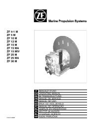
<strong>ZF</strong> 63 A<br />
<strong>ZF</strong> 63<br />
<strong>ZF</strong> 80 A<br />
<strong>ZF</strong> 80-1 A<br />
<strong>ZF</strong> 85 A<br />
FEBRUARY 2006<br />
cod. 310.01.0054i<br />
Repair Manual<br />
and<br />
Spare Parts List
Repair Manualand Spare Parts List Table of contents<br />
TABLE OF CONTENTS<br />
INTRODUCTION. . ................................... 3<br />
1. MAJOR COMPONENTS. . .......................... 5<br />
1.1 TRANSMISSION SET-UP . .......................5<br />
1.2 CLEANERS AND SEALANTS. . . ..................6<br />
1.3 MEASURING TOOLS . ...........................6<br />
1.4 STANDARD TOOLS AND FIXTURE . ..............6<br />
2. SPECIAL TOOLS . . ............................... 7<br />
3. DISASSEMBLY ................................... 9<br />
INTRODUCTION....................................9<br />
3.1 FLUID FILTER . . ................................9<br />
3.1.1 Remove fluid filter . . . .......................9<br />
3.1.2 Suction of transmission fluid . . . ..............9<br />
3.1.3 Suction of transmission fluid on<br />
<strong>ZF</strong> 80 A, <strong>ZF</strong> 80-1 A and <strong>ZF</strong> 85 A . ..............9<br />
3.2 DIPSTICK . . .................................. 10<br />
3.3 BREATHER VALVE. . . ......................... 10<br />
3.4 OUTPUT FLANGE............................. 10<br />
3.5 CONTROL BLOCK . . . ......................... 11<br />
3.5.1 NeutralSafety Switch ..................... 11<br />
3.5.2 NeutralSafety Switch Check . . . ............ 11<br />
3.6 HOUSING . . .................................. 12<br />
3.6.1 Transmission housing halves. . . ............ 12<br />
3.6.2 Shafts and gears ......................... 12<br />
3.6.3 Radialshaft seals......................... 12<br />
3.6.4 Fluid inlet pipe . . ......................... 13<br />
3.7 TAPERED ROLLER BEARINGS. ................ 14<br />
3.7.1 Outer races of tapered roller bearing . ....... 14<br />
3.7.2 Inner races of tapered roller bearings ....... 14<br />
3.8 CLUTCH PACK . .............................. 15<br />
3.8.1 Removalof the clutch discs ................ 15<br />
4. ASSEMBLY...................................... 17<br />
INTRODUCTION.................................. 17<br />
4.1 INPUT SHAFT . . .............................. 17<br />
4.1.1 Mount discs into reversing clutch ........... 17<br />
4.1.2 Install needle bearings and gear............ 18<br />
4.1.3 Assemble butting rings .................... 18<br />
4.1.4 Mounting inner races of tapered<br />
roller bearings. . . ......................... 18<br />
4.1.5 Assemble shims, support shims and<br />
retaining ring............................. 18<br />
4.1.5 Assemble piston rings ..................... 19<br />
4.2 INTERMEDIATE SHAFT. . . ..................... 19<br />
4.2.1 Mounting inner races of tapered<br />
roller bearings. . . ......................... 19<br />
4.3 OUTPUT SHAFT .............................. 19<br />
4.3.1 Mounting inner race of tapered<br />
roller bearing............................. 19<br />
4.4 PREASSEMBLY OF HOUSING ..................20<br />
4.4.1 Assembly of outer races<br />
(tapered roller bearings). ...................20<br />
4.4.2 Installation of fluid suction pipe and baffle. . . . 20<br />
4.4.3 Assembling input shaft seal. . . ..............21<br />
4.4.4 Mounting the breather filter . . . ..............21<br />
4.5 MEASURING THE BEARING CLEARANCE/<br />
ADJUSTING THE PRETENSION OF BEARINGS . . 22<br />
4.5.1 General. . . ................................22<br />
4.5.2 Mounting outer races of tapered roller<br />
bearings into housing . . . ...................22<br />
4.5.3 Inserting gear set into housing ..............22<br />
4.5.4 Measuring bearing clearance on input<br />
shaft . ....................................23<br />
4.5.5 Measuring bearing clearance at<br />
intermediate shaft . . .......................23<br />
4.5.6 Measuring the bearing clearance on the<br />
output shaft...............................23<br />
4.5.7 Adjusting the pretension/clearance of<br />
bearings. . ................................24<br />
4.5.8 Finalassembly of the housing ..............24<br />
4.6 CONTROL BLOCK . . ...........................25<br />
4.6.1 Mounting the controlblock . . . ..............25<br />
4.7 FLUID FILTER . ................................25<br />
4.7.1 Mounting the fluid filter . ...................25<br />
4.8 OUTPUT FLANGE . . ...........................25<br />
4.9 MAKING THE TRANSMISSION<br />
READY FOR OPERATION . . . ...................26<br />
4.9.1 Filling up with transmission Fluid . ..........26<br />
4.9.2 Check fluid level. . . .......................26<br />
5. ADJUSTMENT DATA . . ...........................27<br />
5.1 SHIFTING PRESSURE . . .......................27<br />
5.2 LUBE OIL DELIVERY RATE. . ...................27<br />
6. HYDRAULIC DIAGRAM. ...........................28<br />
7. TIGHTENING TORQUES...........................29<br />
8. FUNCTION TEST . ................................30<br />
9. TROUBLESHOOTING . . ...........................31<br />
10. AUTOMATIC TRANSMISSION FLUID ..............36<br />
11. SPARE PARTS LIST<br />
<strong>ZF</strong><strong>63A</strong>-<strong>ZF</strong>63-<strong>ZF</strong>80A - <strong>ZF</strong>80-1A...............39<br />
Preface . . .........................................39<br />
Name plate . . . ....................................39<br />
FIG. 1 <strong>ZF</strong> 63 A. ....................................40<br />
FIG. 1 <strong>ZF</strong> 63 . . ....................................42<br />
FIG. 1 <strong>ZF</strong> 80 A - <strong>ZF</strong> 80-1 A . . .......................44<br />
1
FIG. 2 <strong>ZF</strong> 63 A .................................... 46<br />
FIG. 2 <strong>ZF</strong> 63 . .................................... 50<br />
FIG. 2 <strong>ZF</strong> 80 A - <strong>ZF</strong> 80-1 A. . ....................... 52<br />
FIG. 3 Mechanical selector valve<br />
<strong>ZF</strong> 63 A - <strong>ZF</strong> 63 - <strong>ZF</strong> 80 A - <strong>ZF</strong> 80-1 A . . . ..... 56<br />
FIG. 4 Old electric selector valve with proportional valves<br />
<strong>ZF</strong> 63 A - <strong>ZF</strong> 63 - <strong>ZF</strong> 80 A - <strong>ZF</strong> 80-1 A . . . ..... 58<br />
FIG. 5 <strong>ZF</strong> 63 A - <strong>ZF</strong> 63 - <strong>ZF</strong> 80 A - <strong>ZF</strong> 80-1 A . . . ..... 60<br />
FIG. 6 Old electric selector valve ON/OFF 12V, 26 bar<br />
<strong>ZF</strong> 63 A - <strong>ZF</strong> 63 - <strong>ZF</strong> 80 A - <strong>ZF</strong> 80-1 A . . . ..... 62<br />
FIG. 7 New electric selector valve ON/OFF 12V - 26 bar<br />
New electric selector valve ON/OFF 24V - 26 bar<br />
<strong>ZF</strong> 63 A - <strong>ZF</strong> 63 - <strong>ZF</strong> 80 A - <strong>ZF</strong> 80-1 A . . ..... 64<br />
FIG. 8 New electric selector valve ON/OFF 12V - 26 bar<br />
with trolling valve<br />
New electric selector valve ON/OFF 24V - 26 bar<br />
with trolling valve<br />
<strong>ZF</strong> 63 A - <strong>ZF</strong> 63 - <strong>ZF</strong> 80 A - <strong>ZF</strong> 80-1 A . . ..... 66<br />
<strong>ZF</strong> 63 A - <strong>ZF</strong> 63 KIT COMPONENTS . . . .............. 68<br />
<strong>ZF</strong> 80 A - <strong>ZF</strong> 80-1 A KIT COMPONENTS .............. 69<br />
12. SPARE PARTS LIST<br />
<strong>ZF</strong> 80 A (016, 017, 018, 019, 020, 021 VERSION)<br />
<strong>ZF</strong> 80-1 A (024, 025, 026, 027, 029, 030 VERSION) . . . 71<br />
Preface . . ........................................ 71<br />
Name plate . . . .................................... 71<br />
FIG. 1 <strong>ZF</strong> 80 A - <strong>ZF</strong> 80-1 A . . . ....................... 72<br />
FIG. 2 <strong>ZF</strong> 80 A - <strong>ZF</strong> 80-1 A . . . ....................... 74<br />
FIG. 3 Mechanical selector valve<br />
<strong>ZF</strong> 80 A - <strong>ZF</strong> 80-1 A . . . ....................... 78<br />
FIG. 4 Old electric selector valve ON/OFF 12V, 26 bar<br />
<strong>ZF</strong> 80 A - <strong>ZF</strong> 80-1 A . . . ....................... 80<br />
FIG. 5 New electric selector valve ON/OFF 12V - 26 bar<br />
New electric selector valve ON/OFF 24V - 26 bar<br />
<strong>ZF</strong> 80 A - <strong>ZF</strong> 80-1 A . . . ....................... 82<br />
FIG. 6 New electric selector valve ON/OFF 12V - 26 bar<br />
with trolling valve<br />
New electric selector valve ON/OFF 24V - 26 bar<br />
with trolling valve<br />
<strong>ZF</strong> 80 A - <strong>ZF</strong> 80-1 A . . . ....................... 84<br />
KIT COMPONENTS <strong>ZF</strong> 80 A - <strong>ZF</strong> 80-1 A .............. 86<br />
2<br />
Repair Manualand Spare Parts List Table of contents<br />
13. SPARE PARTS LIST <strong>ZF</strong> 85 A . . ................... 87<br />
Preface .......................................... 87<br />
Name plate. . ..................................... 87<br />
FIG. 1 <strong>ZF</strong> 85 A . . . ................................. 88<br />
FIG. 2 <strong>ZF</strong> 85 A . . . ................................. 90<br />
FIG. 3 Mechanical selector valve<br />
<strong>ZF</strong>85A.................................... 92<br />
FIG. 4 Electric selector valve ON/OFF 12V - 26 bar<br />
Electric selector valve ON/OFF 24V - 26 bar<br />
<strong>ZF</strong>85A.................................... 94<br />
FIG. 5 Electric selector valve ON/OFF 12V - 26 bar<br />
with trolling valve<br />
Electric selector valve ON/OFF 24V - 26 bar<br />
with trolling valve<br />
<strong>ZF</strong>85A.................................... 96<br />
KIT COMPONENTS <strong>ZF</strong> 85 A ........................ 98<br />
14. SPARE PARTS LIST <strong>ZF</strong> 80A<br />
(<strong>ZF</strong> 85 A DERIVATE VERSION) ................... 99<br />
Preface .......................................... 99<br />
Name plate. . ..................................... 99<br />
FIG. 1 <strong>ZF</strong> 80 A (<strong>ZF</strong> 85 A DERIVATE VERSION) . ..... 100<br />
FIG. 2 <strong>ZF</strong> 80 A (<strong>ZF</strong> 85 A DERIVATE VERSION) . ..... 102<br />
FIG. 3 Mechanical selector valve<br />
<strong>ZF</strong> 80 A (<strong>ZF</strong> 85 A DERIVATE VERSION) . ..... 104<br />
FIG. 4 Electric selector valve ON/OFF 12V - 26 bar<br />
Electric selector valve ON/OFF 24V - 26 bar<br />
<strong>ZF</strong> 80 A (<strong>ZF</strong> 85 A DERIVATE VERSION) . ..... 106<br />
FIG. 5 Electric selector valve ON/OFF 12V - 26 bar<br />
with trolling valve<br />
Electric selector valve ON/OFF 24V - 26 bar<br />
with trolling valve<br />
<strong>ZF</strong> 80 A (<strong>ZF</strong> 85 A DERIVATE VERSION) . ..... 108<br />
KIT COMPONENTS <strong>ZF</strong> 80 A<br />
(<strong>ZF</strong> 85 A DERIVATE VERSION) . . .................. 110
Repair Manualand Spare Parts List Introduction<br />
INTRODUCTION<br />
This manualgives specific instructions for the proper repair on<br />
<strong>ZF</strong> 63 - <strong>ZF</strong> 63 A - <strong>ZF</strong> 80 A - <strong>ZF</strong> 80-1 A - <strong>ZF</strong> 85 A transmissions.<br />
Please follow the procedures carefully to insure quality service.<br />
<strong>ZF</strong> HURTH MARINE recommends to read the manualcompletely<br />
before starting with repairs, as some of the procedures described<br />
are rather complex.<br />
Along with standard tools, <strong>ZF</strong> HURTH MARINE recommends the<br />
use of special tools, necessary to perform repairs correctly. The<br />
special tools are available through your local <strong>ZF</strong> HURTH MARINE<br />
dealer.<br />
This manualis based on the technicalinformation at the time of<br />
printing. The manual has been checked carefully in order to avoid<br />
errors. However <strong>ZF</strong> HURTH MARINE is not liable for any misrepresentations,<br />
errors of description or omissions.<br />
Modifications on future manuals may be introduced without prior<br />
notice.<br />
3
Repair Manualand Spare Parts List Section 1<br />
1. MAJOR COMPONENTS<br />
1.1 TRANSMISSION SET-UP<br />
The main components of the <strong>ZF</strong> Marine Transmissions are:<br />
ITEM DESCRIPTION ITEM DESCRIPTION<br />
1 Two-piece aluminum die cast 2 Gears<br />
1.1 Oilfilter 2.1 Input shaft with reversing clutch pack assembly<br />
1.2 Oildipstick 2.2 Intermediate shaft<br />
1.3 Breather valve 2.3 Output shaft<br />
1.4 Oildrain plug (<strong>ZF</strong> 80A, <strong>ZF</strong> 80-1A, <strong>ZF</strong> 85A) 3 Controlblock<br />
3<br />
1.4<br />
1.2<br />
1<br />
1.3<br />
1.1<br />
2<br />
2.3<br />
2.1<br />
2.2<br />
5
1.2 CLEANERS AND SEALANTS<br />
6<br />
Repair Manualand Spare Parts List Section 1<br />
For cleaning:<br />
Cold cleaner such as benzene, thrichloroethane or Loctite<br />
fast cleaner No. 7063.<br />
| WARNING |<br />
Keep detergents away from your skin, do not drink<br />
and do not inhale their vapors! Always wear protective<br />
gloves and safety glasses!<br />
Note accident prevention rules!<br />
For assembly:<br />
. Loctite 243 medium-hard for securing oilplug on<br />
<strong>ZF</strong> 80 A - <strong>ZF</strong> 80-1 A - <strong>ZF</strong> 85 A<br />
1.3. MEASURING TOOLS<br />
MICROMETER<br />
Measuring gauge from 0-25 mm (0-1.0 in.)<br />
Accurancy of reading 1/100 mm (0.0004 in.)<br />
DIAL INDICATOR GAUGE WITH ARM-TYPE<br />
SUPPORT<br />
DIAL GAUGE INCREMENTS<br />
DIAL FACE CAN BE TURNED<br />
TO ZERO POSITION<br />
ACCURACY OF READING:<br />
SMALL HAND 1 mm (.03937 in)<br />
FEELER GAUGE<br />
LARGE HAND<br />
1/100 mm (.0004 in)<br />
MEASURING DEPTH<br />
APPROX. 11 mm (.433 in)<br />
. Loctite 245 for securing output flange on spline.<br />
. Loctite 518 for housing surfaces.<br />
. Loctite 574 for outer diameter sealing rings.<br />
. Grease: Staburags NBU 30, Klueber Co. for radial<br />
shaft seals.<br />
. ATF FLUID:<br />
3.8 litres (1.0 US.gallons) for <strong>ZF</strong> 63<br />
4.0 litres (1.05 US.gallons) for <strong>ZF</strong> 63 A<br />
5.5 litres (1.5 US.gallons) for <strong>ZF</strong> 80 A - <strong>ZF</strong> 80-1 A<br />
5.5 litres (1.5 US.gallons) for <strong>ZF</strong> 85 A<br />
1.4. STANDARD TOOLS AND FIXTURE<br />
WRENCH for hexagon bolts (8 - 17 - 19 - 22 mm) (7/8")<br />
ALLEN WRENCH (6 mm)<br />
HEXAGON SOCKET WRENCH (6 - 8 - 17 - 19 mm)<br />
TORQUE WRENCH<br />
adjustable up to 180 Nm (152 ft.lb.)<br />
PLASTIC HAMMER (1000 g) and sturdy screwdriver<br />
EXTRACTOR minimum diameter 130 m<br />
PLIER
Repair Manualand Spare Parts List Section 2<br />
2. SPECIAL TOOLS<br />
It is assumed that all standard tools, such as, torque<br />
wrenches, open-end wrenches, allen keys and extractors,<br />
are available.<br />
All fixtures for pressing parts in or out should be used in<br />
conjunction with a hydraulic or manual press.<br />
EXTRACTOR<br />
Tapered roller bearing inner races<br />
Basic Unit P/N 978.25.0017.0 (454421)<br />
ADAPTER for basic unit 978.25.0017.0 (454421).<br />
For bearing input shaft - spline side.<br />
- P/N 978.25.0018.0 (469686) <strong>ZF</strong> 63 A - <strong>ZF</strong> 63<br />
- P/N 978.35.0019.0 (500465) <strong>ZF</strong> 80 A - <strong>ZF</strong> 80-1 A -<br />
<strong>ZF</strong> 85 A<br />
EXTRACTOR SPLIT RING<br />
Input shaft. Taper roller bearing inner race - control<br />
block side. P/N 224.836.009 D (456170)<br />
EXTRACTOR Tapered roller bearing outer races basic<br />
unit P/N 978.25.0021.0 (454422)<br />
BASIC UNIT<br />
Part number<br />
LEGS KIT (composed of three legs)<br />
P/N 978.25.0006.0 (477776)<br />
<strong>ZF</strong> 63<br />
<strong>ZF</strong> 63 A<br />
A B<br />
ADAPTER FOR<br />
BASIC UNIT 454422<br />
<strong>ZF</strong> 80A<br />
<strong>ZF</strong> 80-1 A<br />
50<br />
<strong>ZF</strong> 85 A<br />
<strong>ZF</strong> 80A ]<br />
978.25.0009.0 (477853) l l<br />
978.25.0011.0 (477854) l l l<br />
978.25.0012.0 (477856) l<br />
978.25.0013.0 (477857) l<br />
978.35.0016.0 (477895) l l<br />
] (<strong>ZF</strong> 85 A DERIVATE VERSION)<br />
CLAMPING RING for measuring the bearing clearance<br />
input shaft P/N 219.354.3 (618582)<br />
LEVER<br />
CLAMPING SCREW<br />
INPUT SHAFT<br />
DIAL INDICATOR<br />
MANDREL<br />
For disassembly and assembly<br />
Shaft seal- input side : P/N 224.836.005 (454425)<br />
Shaft seal- output side:<br />
- P/N 224.836.006 (454426) <strong>ZF</strong> 63 A - <strong>ZF</strong> 63<br />
- P/N 978.35.0005.0 (500449) <strong>ZF</strong> 80 A - <strong>ZF</strong> 80-1 A -<br />
<strong>ZF</strong> 85 A<br />
For assembling input shaft seal on the input spline side<br />
Bushing P/N 20.0012.01 to insert input shaft seal<br />
Only for models: <strong>ZF</strong> 63 A - <strong>ZF</strong> 63 - <strong>ZF</strong> 80 A - <strong>ZF</strong> 80-1 A<br />
MandrelP/N 20.0012.02 to assemble input shaft seal<br />
Only for models: <strong>ZF</strong> 63 A - <strong>ZF</strong> 63 - <strong>ZF</strong> 80 A - <strong>ZF</strong> 80-1 A<br />
MandrelP/N 20.1072.01 to assemble input shaft seal<br />
Only for model: <strong>ZF</strong> 85 A - <strong>ZF</strong> 80 A (<strong>ZF</strong> 85 A DERIVATE<br />
VERSION)<br />
7
SHIM<br />
To determinate the correct preload of the tapered roller<br />
bearings.<br />
- P/N 20.1005.00 <strong>ZF</strong> 63 A<br />
- P/N 20.1018.00 <strong>ZF</strong> 63<br />
- P/N 20.1016.00 - <strong>ZF</strong>80 A - <strong>ZF</strong> 80-1 A - <strong>ZF</strong> 85 A<br />
SPECIAL HEX HEAD BOLT WITH BEARING<br />
for measuring the bearing clearance intermediate shaft<br />
P/N. 224.836.008 (458105)<br />
8<br />
Repair Manualand Spare Parts List Section 2<br />
PUNCH<br />
for assembly Seal - suction pipe<br />
- P/N 20.1021.00 <strong>ZF</strong> 80 A - <strong>ZF</strong> 80-1 A - <strong>ZF</strong> 85 A<br />
- P/N 20.1029.00 <strong>ZF</strong> 63 A - <strong>ZF</strong> 63<br />
CENTRE SQUARE PUNCH To position the oilsuction<br />
pipe into housing P/N 20.1041.00
Repair Manualand Spare Parts List Section 3<br />
3. DISASSEMBLY<br />
INTRODUCTION<br />
Clean the transmission thoroughly on the outside before<br />
disassembly.<br />
Swiveling stand <strong>ZF</strong><br />
Output - half side up<br />
3.1 FLUID FILTER<br />
3.1.1 Remove fluid filter<br />
Turn the screw that fixes the oilfilter cover in a counterclockwise<br />
direction and remove the filter from its housing<br />
(item 1, fig. 1-1). Use a 6 mm Allen wrench.<br />
Pull filter element off (item 2, fig.1-1).<br />
Check O-rings (item 3 and 4, fig. 1-1) for wear, replace if<br />
necessary.<br />
3.1.2 Suction of transmission fluid<br />
Push hose of suction pump (item 1, Fig. 1-2) through<br />
the suction pipe (item 2, Fig. 1-2) down to the bottom<br />
of the housing and suck the fluid off.<br />
3.1.3 Suction of transmission fluid on<br />
<strong>ZF</strong> 80A, <strong>ZF</strong> 80-1 A and <strong>ZF</strong> 85 A<br />
Remove the plug (item 3, Fig. 1-2) and let the oil flow<br />
from the proper hole.<br />
+ | IMPORTANT |<br />
The used oil and the oil filter are to be handled as<br />
special waste that pollute the environment.<br />
For the safe disposal of used oil and filter, take all<br />
the measures required by the relevant local rules<br />
and legislation.<br />
The repair area should be clean and well lighted.<br />
<strong>ZF</strong> HURTH MARINE recommends using a swiveling<br />
stand for aiding in assembly and disassembly.<br />
Swiveling stand <strong>ZF</strong><br />
Input - half side up<br />
3<br />
1 3<br />
2<br />
1<br />
4<br />
2<br />
FIG. 1 - 1<br />
FIG. 1 - 2<br />
9
3.2 DIPSTICK<br />
Unscrew dipstick (item 1, Fig. 2-1) (counterclockwise)<br />
and pull out of housing. Replace O-Ring if present<br />
(check parts list section 11).<br />
3.3 BREATHER VALVE<br />
Unscrew breather valve (item 1, Fig. 3-1). Wash valve<br />
in a detergent, let dry and dip in oil, then let oil drip off.<br />
3.4 OUTPUT FLANGE<br />
Lock output flange in swivel frame.<br />
Unscrew hex head bolt (item 1, Fig. 4-1).<br />
Remove disc (item 2, Fig. 4-1) and O-ring (item 3, Fig. 4-<br />
1).<br />
Screw hex bolt (item 1, Fig. 4-1) in again.<br />
Place extractor on the transmission and pull output<br />
flange (item 1, Fig. 4-2) off.<br />
10<br />
Repair Manualand Spare Parts List Section 3<br />
4<br />
1<br />
3<br />
1<br />
2<br />
1<br />
FIG. 2 - 1<br />
1<br />
FIG. 3 - 1<br />
FIG. 4 - 1<br />
FIG. 4 - 2
Repair Manualand Spare Parts List Section 3<br />
3.5 CONTROL BLOCK<br />
Unscrew allen head bolts (item 1, Fig. 5-1)<br />
Pull control block (item 2, Fig. 5-1) together with seal<br />
(item 3, Fig. 5-1) off the input shaft.<br />
Remove key (item 4, Fig. 5-1) from input shaft (item 5,<br />
Fig. 5-1).<br />
3.5.1 Neutral Safety Switch<br />
Unscrew neutralsafety switch (item 1, Fig. 5-2).<br />
Note: Use 7/8 inch wrench for hex bolts.<br />
To reassemble switch:<br />
tightening torque: 25 Nm (18.5 ft.lb.)<br />
3.5.2 Neutral Safety Switch Check<br />
To check for proper operation of the switch perform one<br />
of the following tests:<br />
A: Ohm meter<br />
Connect the ohm meter leads to the terminal connection<br />
of the switch.<br />
With the pin (item 1a Fig. 5-3) extended you should get<br />
a reading, indicating a good switch.<br />
Compressing the pin (item 1b Fig. 5-3) you should have<br />
«O» reading,<br />
B: 12 volt light<br />
Connect the neutralsafety switch with a light in series<br />
to a 12 volt battery. The switch is good when the light<br />
goes out when the center pin (item 1b Fig. 5-3) is compressed.<br />
1<br />
2 3<br />
Battery 12 V DC Lamp 8.4 A<br />
4<br />
Battery 12 V DC Lamp 8.4 A<br />
1<br />
Neutral<br />
position<br />
1a<br />
AorB<br />
position<br />
1b<br />
FIG. 5 - 1<br />
FIG. 5 - 2<br />
FIG. 5 - 3<br />
11
3.6 HOUSING<br />
3.6.1 Transmission housing halves<br />
Using an adequate drift punch, top the locating pins<br />
(item 1, Fig. 6-1a and 6-1b) out of the housing.<br />
Loosen and remove all hex head bolts and lock<br />
washers (item 2 and 3, Fig. 6-1b). Using a plastic hammer<br />
slightly top the split line of the case halves to break<br />
the seal. Then remove the input side of the housing.<br />
3.6.2 Shafts and gears<br />
Take the gear set out of the housing<br />
. Intermediate shaft (item 2, Fig. 6-2).<br />
. Input shaft (item 1, Fig. 6-2).<br />
. Output shaft (item 3, Fig. 6-2).<br />
Check all gears, bearings and three piston rings on the<br />
input shaft (item 4, Fig. 6-2) for signs of wear or failure.<br />
If any of the gears are damaged or showing signs of excessive<br />
wear <strong>ZF</strong> HURTH MARINE recommends replacing<br />
the complete gear set.<br />
When tapered roller bearings on the input shaft need to<br />
be replaced, the butting rings and needle bearings<br />
should also be replaced. To check for correct clutch operation,<br />
rotate the gears on the input shaft. If it is hard<br />
to turn the gears, the clutch is probably damaged.<br />
3.6.3 Radial shaft seals<br />
Input shaft seal<br />
Using a sealmandrelinside the housing top the input<br />
shaft sealout.<br />
Discard sealand replace with a new one. (Fig. 6-3a).<br />
12<br />
Repair Manualand Spare Parts List Section 3<br />
3<br />
1<br />
4<br />
1<br />
1<br />
2<br />
3 2<br />
FIG. 6 - 1a<br />
FIG. 6 - 1b<br />
FIG. 6 - 2<br />
FIG. 6 - 3a
Repair Manualand Spare Parts List Section 3<br />
Output shaft seal<br />
Using a mandrelpunch top the output flange sealout<br />
from the other side of the housing. Discard sealand replace<br />
with a new one. (Fig. 6-3b).<br />
3.6.4 Fluid inlet pipe<br />
Replacing the seal:<br />
<strong>ZF</strong> 63 A - <strong>ZF</strong> 63 (Fig. 6-4a)<br />
. Remove baffle plate (item 2).<br />
. Remove suction pipe (item 3).<br />
. Drive out seal(item 1).<br />
<strong>ZF</strong> 80A - <strong>ZF</strong> 80-1 A - <strong>ZF</strong> 85 A (Fig. 6-4b)<br />
. Remove suction pipe (item 2).<br />
. Drive out seal(item 1).<br />
1<br />
OLD VERSION<br />
1<br />
3<br />
2<br />
3<br />
FIG. 6 - 3b<br />
NEW VERSION<br />
FIG. 6 - 4a<br />
2<br />
FIG. 6 - 4b<br />
13
3.7 TAPERED ROLLER BEARINGS<br />
Check for failed bearings or excessive bearing wear.<br />
3.7.1 Outer races of tapered roller bearing<br />
Remove the outer races out of the housing halves by<br />
means of the specialtool(Fig. 7-1) or by heating the<br />
housing halves in an oven to approx. 120 ëC (248 F):<br />
Put the housing in the oven upside down, so the outer<br />
races will fall down.<br />
| WARNING |<br />
Use protective gloves when handling the heated<br />
housing and outer races.<br />
+ | IMPORTANT |<br />
Regard location of shims under each outer race for<br />
correct position during reassembling.<br />
Shims are located under outer races of the cover<br />
only.<br />
3.7.2 Inner races of tapered roller bearings<br />
NOTE<br />
. Input shaft - spline side<br />
. The extractor (Fig. 7-2a) is required for pulling<br />
the inner races off.<br />
For extracting the inner races proceed as follows:<br />
. Screw in adapter onto the puller (item 1).<br />
. Place adapter onto the roller cage.<br />
. Tighten collar to rollers by means of cap nut (item<br />
2).<br />
. Screw spindle (item 3)against shaft and pull bearing<br />
evenly and carefully off.<br />
| WARNING |<br />
Improper use of the extractor when removing the<br />
races, could cause damage to the race or slip off.<br />
Input shaft - Control block side<br />
The inner race and the gear on the controlblock side<br />
can be removed by using the split ring and a standard<br />
hydraulic press (fig. 7-2b).<br />
Input shaft - Control block side <strong>ZF</strong> 85 A - <strong>ZF</strong> 80A<br />
(<strong>ZF</strong> 85 A DERIVATE VERSION)<br />
. Remove the retaining ring (item 1, Fig. 7-2c) using<br />
a plier.<br />
. Scrap the retaining ring.<br />
. Remove the washer (item 2, Fig. 7-2c).<br />
. Remove the shims (item 3, Fig. 7-2c).<br />
14<br />
Repair Manualand Spare Parts List Section 3<br />
3<br />
2<br />
1<br />
FIG. 7 - 1<br />
INPUT SPLINE SIDE CONTROL BLOCK SIDE<br />
FIG. 7 - 2a FIG. 7 - 2b<br />
1<br />
2<br />
3<br />
FIG. 7 - 2c
Repair Manualand Spare Parts List Section 3<br />
3.8 CLUTCH PACK<br />
3.8.1 Removal of the clutch discs<br />
Control block side (Fig. 8-1a)<br />
<strong>ZF</strong> 63 A - <strong>ZF</strong> 63<br />
. Remove thrust washer (1) off using two screwdrivers.<br />
. Take off gear (2) and, needle bearings (3).<br />
. Removalof pressure plate.<br />
Press snap ring (5) against periphery of pressure<br />
plate (4) by means of screwdrivers. Extract them together.<br />
The discs (6) can now be removed from the<br />
clutch housing.<br />
Control block side (Fig. 8-1b)<br />
<strong>ZF</strong> 80A - <strong>ZF</strong> 80-1 A<br />
. Remove thrust washer (1) off using screwdrivers.<br />
. Take off gear (2), needle bearings (3), and spacer<br />
(7).<br />
. Removalof pressure plate.<br />
Press snap ring (5) against periphery of pressure<br />
plate (4) by means of screwdrivers. Extract them together.<br />
The discs (6) can now be removed from<br />
clutch housing.<br />
Control block side (Fig. 8-1c)<br />
<strong>ZF</strong> 85 A - <strong>ZF</strong> 80A (<strong>ZF</strong> 85 A DERIVATE VERSION)<br />
. Remove thrust washer (1) off using two screwdrivers.<br />
. Take off gear (2) and needle bearing (3).<br />
. Removalof pressure plate.<br />
Press snap ring (5) against periphery of pressure<br />
plate (4) by means of screwdrivers. Extract them together.<br />
The discs (6) can now be removed from the<br />
clutch housing.<br />
2<br />
1<br />
2<br />
2<br />
1<br />
7<br />
5<br />
5<br />
1<br />
5<br />
3<br />
4<br />
4<br />
4<br />
3<br />
3<br />
6<br />
6<br />
6<br />
FIG. 8 - 1a<br />
FIG. 8 - 1b<br />
FIG. 8 - 1c<br />
15
Input spline side (fig. 8-2a)<br />
<strong>ZF</strong> 63 A (no ratio 2.7) - <strong>ZF</strong> 63<br />
. Remove thrust washer (1) off using two screwdrivers.<br />
. Take off gear (2) and needle bearings (3).<br />
. Remove pressure plate (5). Press snap ring (4)<br />
against periphery of pressure plate by means of<br />
screwdrivers. Extract them together. The discs (6)<br />
can now be removed from the clutch housing.<br />
Input spline side (fig. 8-2b)<br />
<strong>ZF</strong> 80A - <strong>ZF</strong> 80-1 A<br />
<strong>ZF</strong> 63 A (only ratio 2.7)<br />
<strong>ZF</strong> 85 A<br />
. Remove thrust washer (1) off using two screwdrivers.<br />
. Take off gear (2), needle bearings (3) and spacer<br />
(4).<br />
. Remove pressure plate (6). Press snap ring (5)<br />
against periphery of pressure plate by means of<br />
screwdrivers. Extract them together.<br />
The discs (7) can now be removed from the clutch<br />
housing.<br />
16<br />
Repair Manualand Spare Parts List Section 3<br />
2<br />
2<br />
4<br />
4<br />
1<br />
5<br />
1<br />
5<br />
6<br />
3<br />
3<br />
6<br />
7<br />
FIG. 8 - 2a<br />
FIG. 8 - 2b
Repair Manualand Spare Parts List Section 4<br />
4. ASSEMBLY<br />
INTRODUCTION<br />
A well-lighted work area that is free from dirt and chips,<br />
will facilitate the work considerably.<br />
<strong>ZF</strong> HURTH MARINE recommends to use a swiveling<br />
stand, described in the disassembly section to aid in<br />
the assembly.<br />
Thoroughly clean all mating surfaces from any Loctite<br />
or gasket material.<br />
| WARNING |<br />
Cleaners and solvents can be toxic and potentially<br />
harmful without proper ventilation.<br />
4.1 INPUT SHAFT<br />
4.1.1 Mount discs into reversing clutch<br />
Equip both sides coupling with new outer disc (item 1,<br />
Fig. 1-1a) and new inner disc (item 2, Fig. 1-1a).<br />
NOTE<br />
. For exact quantity of inner (item 2, Fig. 1-1a) and<br />
outer discs (item 1, Fig. 1-1a), please refer to the<br />
spare parts list at the end of this manual.<br />
. Stagger the position of the notches on the outer<br />
discs as shown in Fig. 1-1b.<br />
Starting with one of the outer discs, bild up the clutch.<br />
The lugs on the outer discs have to be positioned in line<br />
with each other as shown in Fig. 1-1b.<br />
Install snap ring into groove of clutch housing securing<br />
the pressure plate.<br />
Place end disc (item 1, Fig. 1-1c) and snap ring (item 2,<br />
Fig. 1-1c) engaging it into clutch housing groove.<br />
Check correct position of end disc (item 1, Fig. 1-1c).<br />
Repeat same procedure on opposite side of clutch<br />
(Fig. 1-1d).<br />
2<br />
1<br />
FIG. 1 - 1c<br />
Use caution when using such cleaners.<br />
Always wear protective gloves and glasses!<br />
The next assembly procedure requires the following:<br />
. An electric oven or heating lamp for heating the<br />
housing halves will be required when mounting<br />
the bearings.<br />
. A hydraulic or mechanical press<br />
1<br />
2<br />
2<br />
1<br />
FIG. 1 - 1a<br />
FIG. 1 - 1b<br />
FIG. 1 - 1d<br />
17
Repair Manualand Spare Parts List Section 4<br />
4.1.2 Install needle bearings and gear<br />
Input spline side<br />
. Install needle bearing (item 1, fig. 1-2) onto shaft.<br />
. Slide spacer (item 3, fig. 1-2) where required.<br />
. Align splines on clutch discs previously installed<br />
and install gear (item 2, fig. 1-2).<br />
Make sure clutch gear is fully installed, engaging all<br />
clutch discs.<br />
Control block side<br />
. Repeat same procedure of input sline.<br />
Spacer is only in <strong>ZF</strong> 80 A and <strong>ZF</strong> 80-1 A.<br />
4.1.3 Assemble butting rings<br />
NOTE<br />
. Make sure thrust washer is fully pressed on and<br />
gear is free to rotate.<br />
. Thrust washer must not be bent.<br />
Position shaft assembly on suitable holding fixture.<br />
Using a tube with a bore dia. of 35 mm (1.38 inch) in<br />
and a plastic hammer gently drive thrust washer in position.<br />
(item 1, Fig. 1-3). Repeat same procedure on opposite<br />
side.<br />
4.1.4 Mounting inner races of tapered roller<br />
bearings<br />
Heat inner race of tapered roller bearing (item 1, Fig. 1-<br />
4) to approx. 120 ë(248 ëF) and push onto input shaft.<br />
After cooling down, press bearing carefully against button<br />
ring (item 2, Fig. 1-4) by means of a sleeve and a<br />
manualpress or a copper brass punch.<br />
| CAUTION |<br />
Handle heated tapered roller bearing inner race only<br />
with special gloves!<br />
NOTE<br />
For pressing, apply sleeve to inner race but not to<br />
rollers.<br />
4.1.5 Assemble shims, support shims and<br />
retaining ring <strong>ZF</strong> 85 A - <strong>ZF</strong> 80A (<strong>ZF</strong> 85 A<br />
DERIVATE VERSION)<br />
. Place the shims (item 1, Fig. 1-5).<br />
. Install the washer (item 2, Fig. 1-5).<br />
. Put the retaining ring (item 3, Fig. 1-5) in the groove<br />
of the input shaft using a plier.<br />
| WARNING! |<br />
. Correct the shim thickness:<br />
check that there is no slack between washer and<br />
the retaining ring.<br />
. Maximum permissible clearance should be 0.05<br />
mm. Use a feeler gauge to check it.<br />
18<br />
<strong>ZF</strong> 63 A (Ratio= 2.7 only)<br />
<strong>ZF</strong> 80A - <strong>ZF</strong> 80-1 A - <strong>ZF</strong> 85 A<br />
2<br />
3<br />
FIG. 1 - 4<br />
120 ˚C<br />
248 ˚F<br />
1<br />
2<br />
1<br />
D<br />
<strong>ZF</strong> 63 A (no Ratio= 2.7)<br />
<strong>ZF</strong> 63<br />
1<br />
1<br />
2<br />
1<br />
2<br />
FIG. 1 - 2<br />
FIG. 1 - 3<br />
3<br />
FIG. 1 - 5
Repair Manualand Spare Parts List Section 4<br />
4.1.6 Assemble piston rings<br />
Mount piston ring seals (item 1, Fig. 1-6) onto input shaft.<br />
+ | IMPORTANT |<br />
Make sure the interlocking position of the piston<br />
rings are staggered on the shaft.<br />
4.2 INTERMEDIATE SHAFT<br />
4.2.1 Mounting inner races of tapered roller<br />
bearings<br />
Heat inner races of tapered roller bearings (item 1 and<br />
2, Fig. 2-1) to approx. 120 ëC (248 ëF) and push them<br />
onto the intermediate shaft up against the shaft collar.<br />
| WARNING |<br />
Handle heated taper roller bearing inner races only<br />
with protective gloves!<br />
When the inner races have cooled down, drive them<br />
carefully against the collar using a copper/brass punch.<br />
NOTE<br />
Apply copper/brass punch on inner race and not on<br />
the rollers.<br />
4.3 OUTPUT SHAFT<br />
4.3.1 Mounting inner race of tapered roller<br />
bearing<br />
Heat inner races of taper roller bearings (item 1 and 2,<br />
Fig. 3-1) to approx. 120 ëC (248ëF) and push them onto<br />
output shaft up against shaft collar.<br />
| CAUTION |<br />
Handle heated tapered roller bearing inner races<br />
only with protective gloves!<br />
When the inner races have cooled down, drive them<br />
carefully against the collar using a copper/brass<br />
punch.<br />
NOTE<br />
Apply copper/brass punch on inner race and not on<br />
the rollers.<br />
120 ˚C<br />
248 ˚F<br />
120 ˚C<br />
248 ˚F<br />
120 ˚C<br />
248 ˚F<br />
120 ˚C<br />
248 ˚F<br />
1<br />
2<br />
1<br />
1<br />
2<br />
FIG. 1 - 6<br />
FIG. 2 - 1<br />
FIG. 3 - 1<br />
19
4.4 PREASSEMBLY OF HOUSING<br />
4.4.1 Assembly of outer races<br />
(tapered roller bearings)<br />
Heat output half of the housing (item 1, Fig. 4-1) in an<br />
oven to approx. 120 ëC (248 ëF).<br />
Insert outer races (item 2, Fig.4-1) into housing.<br />
| WARNING |<br />
Handle heated tapered roller bearings outer races<br />
on with protective gloves.<br />
When housing has cooled down to ambient temperature,<br />
with a copper/brass punch seat outer races carefully<br />
into housing.<br />
4.4.2 Installation of fluid suction pipe and<br />
baffle<br />
4.4.2.1 Installation of fluid suction pipe<br />
. Position oilsuction pipe (item 1, Fig. 4-2a) in the<br />
housing.<br />
. Put one drop of Loctite 243 into screw threaded<br />
hole.<br />
. Lightly tighten the screw (item 3, Fig. 4-2a).<br />
. Insert centre square punch and tighten definitely<br />
the screw.<br />
. Adjust oilsuction pipe to measure "A" (A=26 mm)<br />
(Fig. 4-2b).<br />
. Put some ATF fluid on the seal seat and on the oil<br />
suction pipe using a brush.<br />
. Press into housing over the oilsuction pipe the seal<br />
(item 2, fig. 4-2c) using the appropriate punch<br />
(Fig. 4-2c).<br />
4.4.2.2 Installation of baffle (Fig. 4-2d)<br />
(<strong>ZF</strong> 63 A - <strong>ZF</strong> 63)<br />
Put one drop of Loctite 243 on the screw thread (item 1)<br />
and screw baffle plate (item 2) into the housing. After<br />
tightening the screws bend plate lugs when present<br />
over the hexagon of screws (see fig. 4-2d).<br />
20<br />
Repair Manualand Spare Parts List Section 4<br />
1<br />
2<br />
FIG. 4 - 2a<br />
1 A<br />
FIG. 4 - 2b<br />
OLD VERSION<br />
4<br />
OLD VERSION<br />
1<br />
3<br />
1<br />
4<br />
3<br />
2<br />
<strong>ZF</strong>80 A - <strong>ZF</strong>80-1 A<br />
<strong>ZF</strong><strong>63A</strong> - <strong>ZF</strong>63<br />
1<br />
3<br />
<strong>ZF</strong>85 A<br />
2<br />
1<br />
2<br />
NEW VERSION<br />
FIG. 4 - 2c<br />
FIG. 4 - 1<br />
1<br />
3<br />
NEW VERSION<br />
1<br />
1<br />
3<br />
A<br />
FIG. 4 - 2d
Repair Manualand Spare Parts List Section 4<br />
4.4.3 Assembling input shaft seal<br />
Apply thin coat of Loctite 574 on periphery of new radial<br />
shaft sealrings (item 1, Fig. 4-3a and Fig. 4-3b) and<br />
grease lips with KLUEBER STABURAGS NBU 30.<br />
Put it onto the mounting mandrel.<br />
Drive shaft sealuniformly into the housing by tapping<br />
slightly onto the mounting mandrel.<br />
NOTE<br />
The sealing lip (A) on the shaft seal should point into<br />
the inside of the housing. The radial shaft seal must<br />
be adjusted so that the sealing lip runs on the<br />
grounded surface of the shaft.<br />
ALTERNATIVELY (Fig. 4-3c):<br />
For models <strong>ZF</strong> 63 A - <strong>ZF</strong> 63 - <strong>ZF</strong> 80A - <strong>ZF</strong> 80-1 A<br />
. Smear loctite 574 on the outside diameter of the input<br />
shaft seal using a roller.<br />
. Lubricate the inside lip with Kluber Staburags<br />
NBU30 grease.<br />
. Insert the input shaft seal(item 2) into input shaft<br />
using the appropriate bushing p/n 20.0012.01 (item 1).<br />
. Use mandrelp/n 20.0012.02 (item 3) to position the<br />
input shaft sealin the correct way.<br />
For model <strong>ZF</strong> 85 A - <strong>ZF</strong> 80A (<strong>ZF</strong> 85 A DERIVATE<br />
VERSION)<br />
. Smear loctite 574 on the outside diameter of the input<br />
shaft seal using a roller.<br />
. Lubricate the inside lip with Kluber Staburags<br />
NBU30 grease.<br />
. Insert the input shaft seal(item 2) into input shaft using<br />
the appropriate mandrelp/n 20.1072.01 (item 1).<br />
. Position the input shaft sealin the correct way.<br />
4.4.4 Mounting the breather filter<br />
Due to the taper thread, the breather (item 1, Fig. 4-4)<br />
need not to be coated with Loctite 243.<br />
Apply thin coat of Loctite 574 to the oil breather (item 1,<br />
Fig. 4-4).<br />
Tighten carefully during assembly (hand-tight).<br />
Cheek leakage during a later test run. Retighten<br />
slightly if it leaks.<br />
1<br />
FIG. 4 - 3a<br />
<strong>ZF</strong> 63 - <strong>ZF</strong> 63 A<br />
<strong>ZF</strong> 80A - <strong>ZF</strong> 80-1 A<br />
3<br />
1<br />
1 mm<br />
2<br />
1<br />
A<br />
1<br />
1 mm<br />
A<br />
FIG. 4 - 3b<br />
<strong>ZF</strong> 85 A<br />
<strong>ZF</strong> 80A (<strong>ZF</strong> 85 A DERIVATE VERSION)<br />
1<br />
2<br />
FIG. 4 - 3c<br />
FIG. 4 - 4<br />
21
4.5 MEASURING THE BEARING CLEARANCE/ADJUSTING THE PRETENSION<br />
OF BEARINGS<br />
4.5.1 General<br />
The required pretension/play of bearings of the individualshafts<br />
in the housing is obtained by using shims<br />
of different thickness under the outer races of the taper<br />
roller bearings. Shims which have been removed during<br />
disassembly may be reused.<br />
First adjustment must refer to bearing clearance.<br />
Take out from the front cover (Fig. 5-1) at least shims of<br />
0.2 mm (0.0079 in.) thickness from the shims packages<br />
which were removed during disassembly.<br />
Adjustment values<br />
Pretension (mm)<br />
Shaft Input Intermediate Output<br />
<strong>ZF</strong> 80 A - <strong>ZF</strong> 80-1 A 0.02-0.12 0.00-0.12 0.00-0.12<br />
<strong>ZF</strong> 85 A - <strong>ZF</strong> 80 A ] 0.02-0.12 0.00-0.12 0.1-0.15<br />
<strong>ZF</strong> 63 A - <strong>ZF</strong> 63 0.02-0.12 0.00-0.12 0.05-0.15<br />
Pretension (inches)<br />
Shaft Input Intermediate Output<br />
<strong>ZF</strong> 80 A - <strong>ZF</strong> 80-1 A 0.001-0.005 0.000-0.005 0.000-0.005<br />
<strong>ZF</strong> 85 A - <strong>ZF</strong> 80 A ] 0.001-0.005 0.000-0.005 0.004-0.006<br />
<strong>ZF</strong> 63 A - <strong>ZF</strong> 63 0.001-0.005 0.000-0.005 0.002-0.006<br />
] (<strong>ZF</strong> 85 A DERIVATE VERSION)<br />
4.5.2 Mounting outer races of tapered roller<br />
bearings into housing<br />
Heat input half housing (item 1, Fig. 5-2) in an oven to<br />
approx. 120 ëC (248 ëF) and insert shims (item 2) and<br />
outer races (item 3) of bearings into it.<br />
| WARNING |<br />
Handle heated housing half only with protective<br />
gloves!<br />
When half housing has cooled down to ambient temperature,<br />
press outer races carefully down using a copper/brass<br />
punch.<br />
4.5.3 Inserting gear set into housing<br />
Finish housing mating face halves with an oilstone.<br />
| CAUTION |<br />
Make sure to keep any dirt out of housing.<br />
. Holding the half housing on a swiveling stand, insert<br />
gears into it.<br />
. Mount input housing half (item 1, Fig. 5-3) with all<br />
bolts, lock washers (item 2 and 3, Fig. 5-3) and parallel<br />
pins (item 4, Fig. 5-3).<br />
. Tightening torque of bolts: 40 Nm (30 ft.lb.).<br />
22<br />
Repair Manualand Spare Parts List Section 4<br />
3<br />
2<br />
3<br />
1<br />
1<br />
2<br />
4 3 2<br />
1<br />
FIG. 5 - 1<br />
FIG. 5 - 2<br />
FIG. 5 - 3
Repair Manualand Spare Parts List Section 4<br />
4.5.4 Measuring bearing clearance on input<br />
shaft<br />
a) Turn input shaft severaltimes to permit bearings to<br />
seat.<br />
b) Fit clamping ring (tool p/n 219.354.3 (618582)) to the<br />
spline of the input shaft (item 1, Fig. 5-4).<br />
c) Adjust to «O», dialindicator to obtain accurate reading.<br />
d) With two levers carefully pry on the clamping ring<br />
and record end play of shaft.<br />
NOTE<br />
This step must be done very carefully to obtain the<br />
actual bearing clearance.<br />
e) Carry out steps, a) and d) severaltimes.<br />
f) The bearing clearance measured plus the pretension<br />
required in section 5.1 determine the required thickness<br />
of shims.<br />
4.5.5 Measuring bearing clearance at<br />
intermediate shaft<br />
a) Unscrew plug (item 1, Fig. 5-5a) from the housing.<br />
b) Screw in specialtool(p/n 224.836.008 (458105))<br />
(item 2, Fig. 5-5a) into intermediate shaft hole.<br />
c) Mount dialgauge support securely onto housing.<br />
d) Turn intermediate shaft severaltimes to permit bearings<br />
to seat.<br />
e) Adjust the dial indicator needle on top of the bolt<br />
head and «O» to dialindicator (Fig. 5-5b).<br />
f) Screw hexagon nut carefully against housing (intermediate<br />
shaft moves up) untilbearing clearance is<br />
overcome (Fig. 5-5b).<br />
NOTE<br />
This step should be done very carefully to obtain the<br />
actual bearing clearance.<br />
g) Carry out steps d) and f) severaltimes.<br />
h) The clearance measured plus the pretension required<br />
in section 5.1 determine the required thickness<br />
of shims.<br />
4.5.6 Measuring the bearing clearance on<br />
the output shaft<br />
a) Insert output flange onto the output shaft and screw<br />
in nut ring.<br />
b) Install bolt and spacer on input shaft.<br />
c) Turn output shaft repeatedly to permit bearings to seat.<br />
d) Mount dialgauge support securely onto housing.<br />
e) Place dial gauge onto top of the output shaft and adjust<br />
it to «0» reading.<br />
f) Lift output shaft carefully, using two screwdrivers,<br />
and record measurement (Fig. 5-6).<br />
NOTE<br />
This step should be done very carefully to obtain the<br />
actual bearing clearance.<br />
g) Carry out steps c) and f) for severaltimes.<br />
h) The bearing clearance measured plus the pretension<br />
required in section 5.1 will determine the required<br />
thickness of shims.<br />
1<br />
2<br />
1<br />
FIG. 5 - 4<br />
FIG. 5 - 5a<br />
FIG. 5 - 5b<br />
FIG. 5 - 6<br />
23
4.5.7 Adjusting the pretension/clearance of<br />
bearings<br />
When the thickness of shims has been determined, the<br />
transmission must be disassembled again.<br />
a) Using a adequate drift punch, drive the parallel pins<br />
(item 1, Fig. 5-7a) with slight blows, out of the housing.<br />
b) Loosen hex bolts (item 2 and 3, Fig. 5-7a) with lockwashers<br />
(item 4, Fig. 5-7a) and remove input side of<br />
housing (item 5, Fig. 5-7a).<br />
c) Pull outer races of bearings out of the input side of<br />
the housing using the extracting unit (Fig. 5-7b) or<br />
heating the half housing in an oven to approx.<br />
120ëC (248ëF) and remove the outer races of bearings<br />
together with shims.<br />
| WARNING |<br />
Handle heated housing half and outer race only with<br />
protective gloves!<br />
NOTE<br />
Make sure to keep the shims with each outer race<br />
and not mix them together.<br />
4.5.8 Final assembly of the housing<br />
a) Heat input side of the housing in an oven to approx.<br />
120ëC (248 ëF).<br />
| WARNING |<br />
Handle heated housing only with protective gloves!<br />
b) Insert the required shims for proper pretension into<br />
bearings bore under bearing outer race.<br />
c) Insert outer races of bearings. When the housing<br />
has reached ambient temperature, drive outer races<br />
of bearings down to the stop, using a copper punch.<br />
d) Insert shafts.<br />
e) Fill space between seal and dust lips of shaft seal<br />
rings with a high quality bearing grease (Staburags<br />
Kluber NBU 30).<br />
f) Apply a thin coat of Loctite 518 on mating surface of<br />
input side of the housing and join both housing<br />
halves together.<br />
g) Drive parallel pins into housing to align housing<br />
halves, before tightening.<br />
h) Install mounting bolts (item 2 and 3, Fig. 5-7a) and<br />
torque them to 40 Nm (30 ft.lb.).<br />
NOTE<br />
There must be not measurable bearing clearance.<br />
| WARNING |<br />
The necessary time for a complete polymerization is<br />
5 hours: we recommend therefore to clean carefully<br />
the mating surfaces with Loctite 7063 cleaner before<br />
applying the Loctite 518 and wait the requested<br />
time before the spin test.<br />
24<br />
Repair Manualand Spare Parts List Section 4<br />
50<br />
1<br />
A B<br />
ADAPTER FOR<br />
BASIC UNIT 454422<br />
1<br />
4 2<br />
5<br />
BASIC UNIT<br />
4<br />
3<br />
FIG. 5 - 7a<br />
FIG. 5 - 7b
Repair Manualand Spare Parts List Section 4<br />
4.6 CONTROL BLOCK<br />
4.6.1 Mounting the control block<br />
NOTE<br />
Piston rings (item 1, Fig. 6-1) have to be replaced, if<br />
thickness is less than 2.39 mm (0.094in).<br />
a) Insert key (item 2, Fig. 6-1) into groove of shaft.<br />
b) Place new seal (item 3, Fig. 6-1) onto control block.<br />
c) Align key and slot in rotor pump.<br />
d) Slide control block carefully on input shaft.<br />
e) Insert lock washers (item 4, Fig. 6-1) on socket head<br />
bolts (item 5, Fig. 6-1) and provide screw threads<br />
each with a drop of Loctite 243.<br />
f) Tight control block bolts. Tightening torque:<br />
18 Nm (14 ft.lb.).<br />
4.7 FLUID FILTER<br />
4.7.1 Mounting the fluid filter<br />
. Wet O-rings (item 1 and 2, Fig. 7-1) with some ATF<br />
fluid and mount them.<br />
. Install filter element (item 3, Fig. 7-1) into the transmission.<br />
. Lock cover (item 4 Fig. 7-1) to the transmission<br />
using an allen wrench. Tightening torque: min. 5<br />
Nm - max 8 Nm (min. 4 ft.lb. - max 6 ft.lb.)<br />
4.8 OUTPUT FLANGE<br />
Provide spline (X) of output shaft with a thin coat of Loctite<br />
245 and sealing lip (Z) of shaft seal with a thin coat<br />
of ATF fluid. (Fig. 8-1)<br />
Fit output flange (item 1, Fig. 8-1).<br />
Provide O-ring (item 2, Fig. 8-1) with ATF fluid and insert<br />
into output flange.<br />
Tight output flange down on output shaft with bolt (item<br />
3, Fig 8-1) and washer (4).<br />
Tightening torque:<br />
<strong>ZF</strong> 63 A - <strong>ZF</strong> 63 : 100 Nm (74 ft.lb.)<br />
<strong>ZF</strong> 80 A - <strong>ZF</strong> 80-1 A : 100 Nm (74 ft.lb.)<br />
<strong>ZF</strong> 85 A : 100 Nm (74 ft.lb.)<br />
3<br />
5<br />
2<br />
4<br />
1<br />
4<br />
Z<br />
3<br />
X<br />
1<br />
2<br />
4<br />
3<br />
FIG. 6 - 1<br />
2<br />
1<br />
FIG. 7 - 1<br />
FIG. 8 - 1<br />
25
4.9 MAKING THE TRANSMISSION<br />
READY FOR OPERATION<br />
4.9.1 Filling up with transmission Fluid<br />
Filling with ATF fluid into the fluid filter opening. (Fig. 9-<br />
1)<br />
Quantity:<br />
<strong>ZF</strong> 63 : 4.0 US-qts (3.8 liters)<br />
<strong>ZF</strong> 63 A : 4.2 US-qts (4.0 liters)<br />
<strong>ZF</strong> 80 A - <strong>ZF</strong> 80-1 A : 5.8 US-qts (5.5 liters)<br />
<strong>ZF</strong> 85 A : 5.8 US-qts (5.5 liters)<br />
ATF (Automatic Transmission Fluid) such as, per list on<br />
section IX.<br />
Fit filter element as specified in section 4.7.1.<br />
4.9.2 Check fluid level<br />
Carry out a trial run after oil filling.<br />
Set shifting lever to neutral position (N). Start engine<br />
and let it run idle for a short time to fill the cooler and<br />
pipelines with transmission oil. Stop the engine and<br />
check oil level again. If necessary, top up with oil. Excessive<br />
oil should be removed. The fluid level on the<br />
dipstick (item 1, figure 9-2) should be between the<br />
min. and max. marks. The fluid level should be<br />
checked again after a short driving period.<br />
NOTE<br />
Some transmissions may have different oil dipsticks,<br />
depending on the version:<br />
A) When inserted into the housing hole, it expands by<br />
turning the handle in clockwise direction. (Fig. 9-2<br />
item A)<br />
B) It is threaded (Fig. 9-2 item B).<br />
+ | IMPORTANT |<br />
Oil check with threaded dipstick (B) must be done in<br />
a different way compared with the one not threaded<br />
(A):<br />
A) Oildipstick and housing hole not threaded: dipstick<br />
completely inserted into hole.<br />
B) Oildipstick and housing hole threaded: dipstick not<br />
inserted into the housing hole (not screw in).<br />
26<br />
Repair Manualand Spare Parts List Section 4<br />
A<br />
MAX<br />
MIN<br />
1<br />
Housing<br />
B<br />
MAX<br />
MIN<br />
FIG. 9 - 1<br />
O-RING<br />
Housing<br />
FIG. 9 - 2
Repair Manualand Spare Parts List Section 5<br />
5. ADJUSTMENT DATA<br />
5.1 SHIFTING PRESSURE<br />
SHIFTING PRESSURE (bar)<br />
30<br />
25<br />
22<br />
21.5<br />
20<br />
15<br />
10<br />
5<br />
0<br />
0<br />
0<br />
500 1000 1500 2000 2500 3000 3500 4000 4500 5000<br />
DRIVING SPEED (rpm)<br />
5.2 LUBE OIL DELIVERY RATE<br />
DELIVERY RATE ( /min)<br />
30<br />
25<br />
20<br />
15<br />
10<br />
5<br />
0<br />
0<br />
MAX.<br />
MIN.<br />
<strong>ZF</strong> 63 A - <strong>ZF</strong> 63 - <strong>ZF</strong> 80 A; mechanical selector valve 23 bar p/n 3312 108 001<br />
<strong>ZF</strong> 80-1 A - <strong>ZF</strong> 85 A - <strong>ZF</strong> 80 A (<strong>ZF</strong> 85 A DERIVATE VERSION); mechanical selector valve 26 bar p/n 3313 108 001<br />
7.91<br />
7.39<br />
6.86<br />
6.33<br />
5.80<br />
5.28<br />
4.75<br />
4.22<br />
3.69<br />
3.17<br />
2.64<br />
2.11<br />
1.58<br />
1.05<br />
0.53<br />
0<br />
500 1000 1500 2000 2500 3000 3500 4000 4500 5000<br />
DRIVING SPEED (rpm)<br />
<strong>ZF</strong> 63 A - <strong>ZF</strong> 63 - <strong>ZF</strong> 80 A; mechanical selector valve 23 bar p/n 3312 108 001<br />
<strong>ZF</strong> 80-1 A - <strong>ZF</strong> 85 A - <strong>ZF</strong> 80 A (<strong>ZF</strong> 85 A DERIVATE VERSION); mechanical selector valve 26 bar p/n 3313 108 001<br />
MIN. ALL MODELS<br />
400<br />
350<br />
300<br />
250<br />
200<br />
150<br />
100<br />
50<br />
SHIFTING PRESSURE (psi)<br />
DELIVERY RATE (gal. /min)<br />
27
6. HYDRAULIC DIAGRAM<br />
28<br />
A B<br />
= Shifting pressure 21.5 +2 bar<br />
= Fluid 2 +0.5 bar<br />
= Leakage fluid<br />
Direction of<br />
water flow<br />
Repair Manualand Spare Parts List Section 6<br />
Connection for<br />
temperature probe<br />
indicating at abt.<br />
110°C 3/8” - 18 NPSF<br />
oil cooler<br />
Measuring point for shift pressure M10x1<br />
Lube pressure relief valve<br />
Shifting<br />
pressure<br />
relief valve<br />
Basic lubricating throttle valve<br />
Fluid delivery pump<br />
A<br />
0<br />
B<br />
Fluid filter<br />
Filte grade 60µ<br />
Neutral position<br />
switch indication<br />
by electric signal<br />
Shifting valve<br />
for A-0-B<br />
position<br />
Fluid sump<br />
Illustration shows shifting pos. «B»
Repair Manualand Spare Parts List Section 7<br />
7. TIGHTENING TORQUES<br />
PART SIZE<br />
Mounting brackets bolts<br />
<strong>ZF</strong> 63 A - <strong>ZF</strong> 63<br />
Mounting brackets bolts<br />
<strong>ZF</strong> 80 A - <strong>ZF</strong> 80-1 A - <strong>ZF</strong> 85 A<br />
Output flange bolt<br />
<strong>ZF</strong> 63 A - <strong>ZF</strong> 63<br />
TORQUE<br />
IN lb.ft.<br />
TORQUE<br />
IN Nm<br />
LOCTITE<br />
M12 min 55.5 - max 57 min 75 - max 77 -<br />
M12 min 55.5 - max 57 min 75 - max 77 -<br />
M16 74 100 243<br />
Housing bolts M10 30 40 -<br />
Control block bolts M8 13 18 243<br />
Shifting lever bolt M8 17 23 -<br />
Output flange bolt<br />
<strong>ZF</strong> 80 A - <strong>ZF</strong> 80-1 A - <strong>ZF</strong> 85 A<br />
M16 74 100 243<br />
Fluid filter bolt M8 min 4 - max 6 min 5 - max 8 -<br />
Oilbreather - Hand tight Hand tight 574<br />
Fluid dipstick - Hand tight Hand tight -<br />
Oildrain plug - 30 40 243<br />
Stud bolt M16 26 35 243<br />
Controlblock stop screw - 9 12 -<br />
Controlblock pressure screw M10 9 12 -<br />
Screw <strong>ZF</strong> 63 A M5 4 5 243<br />
Screw <strong>ZF</strong> 80 A - <strong>ZF</strong> 80-1 A - <strong>ZF</strong> 85 A M6 7 9 243<br />
Neutralsafety switch - 18.5 25 -<br />
Control block guide bolt - 9 12 -<br />
Control block temperature plug - 26 35 -<br />
29
8. FUNCTION TEST<br />
30<br />
Repair Manualand Spare Parts List Section 8<br />
When the transmission has been completely assembled<br />
and filled up with transmission fluid, it would be convenient<br />
to make a function test.<br />
This test can be carried out on a bench test rig, or in a<br />
boat. If no fluid cooler can be connected, a hydraulic<br />
hose must be connected between the inlet and outlet<br />
of the hydraulic pump.<br />
Measuring instruments required:<br />
. Pressure gauge 0-40 bar (0-580 psi), with connecting<br />
thread M10x1.<br />
. Temperature gauge 0-120ëC (0-250ëF) connecting<br />
thread 3/8«-18NPSF.<br />
. Flow meter 0-35 liters/min (0-10 gals/min).<br />
The function test should be carried out follows:<br />
Motor speed<br />
rpm<br />
Shift lever<br />
position<br />
Tests to be carried out:<br />
1. Fluid leaks<br />
2. Noise emission<br />
3. Output direction of rotation, LH/RH<br />
4. Lube oiltemperature<br />
5. Shifting pressure<br />
6. Lube oilflow rate<br />
Temperature<br />
Durat.<br />
minutes<br />
800-1000 neutral40ëC/104 ëF 5 1, 2<br />
600-800<br />
(idling speed)<br />
AB<br />
position repeatedly<br />
Test<br />
40ëC/104 ëF - 1, 2, 3<br />
1500-2500 B position 80ëC / 176 ëF - 1, 2, 4<br />
600-800<br />
(idling speed)<br />
AB<br />
position repeatedly<br />
80ëC/176 ëF - 1, 2, 3<br />
idling - max. speed A position 80ëC/176 ëF - 1, 2, 5 ] ,6 ]<br />
600-800<br />
(idling speed)<br />
A->B<br />
position 80ëC/176 ëF<br />
- - 1, 2<br />
idling - max. speed B position 80ëC/176 ëF - 1, 2, 5 ] ,6 ]<br />
] At different speeds.<br />
80ëC/176 ëF -
Repair Manualand Spare Parts List Section 9<br />
9. TROUBLESHOOTING<br />
In case of trouble, check first whether all items of the mounting and operating instructions have been completed<br />
with. The subsequent tables will assist you in troubleshooting.<br />
Symptom Possible cause Remedy<br />
1. Transmission cannot be shifted.<br />
2. Delayed shift time.<br />
3. Clutch is slipping, i.e. propeller<br />
speed too low as compared to<br />
engine speed.<br />
4. Transmission locked in gear.<br />
5. Output shaft turns in neutralposition.<br />
6. Shifting pressure too low.<br />
1.1 Shifting lever is loose.<br />
1.2 Remote controldoes not permit<br />
lever travel required.<br />
1.3 Remote controlfaulty.<br />
1.4 No shifting pressure available.<br />
2.1 Shift linkage misadjust not allowing<br />
full engagement.<br />
3.1 Inadmissible fluid used.<br />
3.2 Fluid contains water.<br />
3.3 Shifting pressure too low.<br />
3.4 Wear on clutch discs.<br />
3.5 Piston rings are damaged.<br />
4.1 Medium piston ring in input shaft in<br />
control block is faulty.<br />
4.2 Warped discs due to overheating of<br />
slipping clutch.<br />
4.3 Needle bearings on input shaft are<br />
worn out.<br />
5.1 Rotary slide valve in control block is<br />
worn.<br />
5.2 Faulty needle bearing on input shaft.<br />
5.3 Warped discs due to overheating of<br />
slipping clutch.<br />
6.1 Fluid filter clogged.<br />
6.2 Fluid level in transmission too low.<br />
6.3 Fluid pump is worn out.<br />
6.4 Spring in shifting pressure relief valve<br />
is broken.<br />
6.5 Piston rings on input shaft are faulty.<br />
6.6 Piston rings in clutch are faulty.<br />
1.1 Tighten clamping bolt on shifting lever.<br />
1.2 Lift remote controloff, if gears can be<br />
shifted by hand, adjust remote control<br />
1.3 Repair remote control.<br />
1.4 Refer to 7.<br />
2.1 Lift remote controloff, if gear can be.<br />
shifted by hand, adjust remote control.<br />
If the transmission cannot be shifted<br />
correctly by hand, replace the control<br />
block.<br />
3.1 Drain fluid, refill with prescribed fluid,<br />
flush transmission while engine runs<br />
in neutral position drain fluid, refill<br />
transmission.<br />
3.2 Refer to 9.<br />
3.3 Refer to 6.<br />
3.4 Disassemble transmission, replace<br />
clutch discs.<br />
3.5 Disassemble transmission, replace<br />
piston rings.<br />
4.1 Remove control block, replace piston<br />
ring, if control block is worn, replace<br />
likewise.<br />
4.2 Refer to 3.<br />
4.3 Disassemble transmission, replace<br />
needle bearing and check for damage<br />
input shaft and gears.<br />
5.1 Replace control block.<br />
5.2 Disassemble transmission and input<br />
shaft, replace bearing concerned and<br />
other damaged parts.<br />
5.3 Refer to 3.<br />
6.1 Replace fine filter.<br />
6.2 Top-up with fluid; in case of fluid loss<br />
check transmission, cooler and<br />
pipelines for leakage also refer to<br />
10 through 13.<br />
6.3 Replace control block containing fluid<br />
pump.<br />
6.4 Replace control block.<br />
6.5 Remove control block and replace<br />
piston rings. In case of wear in control<br />
block due to faulty piston rings<br />
replace block as well.<br />
6.6 Disassemble transmission, replace<br />
piston rings..<br />
31
Symptom Possible cause Remedy<br />
7. No shifting pressure available.<br />
8. Excessive fluid temperature.<br />
9. Water in the fluid, fluid looks milky.<br />
10. Fluid leakage at input or output<br />
shaft<br />
11. Fluid leakage at breather.<br />
12. Fluid leakage at joints or screw connections.<br />
32<br />
Repair Manualand Spare Parts List Section 9<br />
7.1 Direction of engine rotation does not<br />
agree with arrow on transmission<br />
front cover.<br />
7.2 No fluid in the transmission.<br />
7.3 Fine filter is dirty.<br />
7.4 Fluid level in transmission is too low.<br />
7.5 Fluid pump worn out.<br />
7.6 Pump key in input shaft for fluid pump<br />
drive is broken.<br />
7.7 Spring of shifting pressure relief valve<br />
is broken.<br />
8.1 Fluid cooler is too small.<br />
8.2 Excessive fluid in transmission.<br />
8.3 Fluid cooler is dirty on water side.<br />
8.4 Worn fluid pump in control block.<br />
8.5 Faulty piston rings in control block.<br />
8.6 Clutch is slipping.<br />
8.7 Clutch does not open completely due<br />
to worn disc support.<br />
8.8 Clutch does not open completely due<br />
to broken cup springs.<br />
8.9 With fluid cooler in bypass and unfavorable<br />
arrangement of pipelines too<br />
little coolant water flows through<br />
bypass to cooler.<br />
9.1 Fluid cooler faulty.<br />
9.2 High water level in engine compartment,<br />
water entering at output shaft<br />
seal.<br />
10.1 Breather clogged with paint or dirt<br />
10.2 Shaft sealfaulty<br />
10.3 Excessive fluid in transmission<br />
7.1 Replace with suitable rotation engine.<br />
7.2 Refill with fluid.<br />
7.3 Replace fine filter.<br />
7.4 Top-up with fluid. In case of loss of<br />
fluid check transmission, cooler and<br />
pipelines for leakage, also refer to<br />
10 through 13.<br />
7.5 Replace control block.<br />
7.6 Remove control block. Replace pump<br />
key, and any other faulty parts.<br />
7.7 Replace control block.<br />
8.1 Use a larger fluid cooler.<br />
8.2 Remove excessive fluid with commercialsuction<br />
pump.<br />
8.3 Detach coolant water lines and clean<br />
fluid cooler on water side.<br />
8.4 Replace control block containing fluid<br />
pump.<br />
8.5 Remove control block, replace piston<br />
rings. In case of wear in the control<br />
block due to faulty piston rings replace<br />
control block as well.<br />
8.6 Refer to 3.<br />
8.7 Dismount transmission and clutch, replace<br />
all faulty parts.<br />
8.8 Dismount transmission and clutch, replace<br />
all faulty parts.<br />
8.9 Correct bypass pipeline.<br />
9.1 Repair leakage at cooler or replace<br />
cooler. Change transmission fluid.<br />
9.2 Remedy cause for water level in engine<br />
compartment. Change transmission<br />
fluid.<br />
10.1 Remove paint or dirt from breather<br />
Replace seal. If seal location on<br />
shaft is worn, regrind.<br />
10.3 Remove excessive fluid with<br />
commercialsuction pump.<br />
11.1 Excessive fluid in transmission. 11.1 Pump excessive fluid out with commercialhand<br />
pump.<br />
12.1 Bolts are not tight at the prescribed<br />
torque.<br />
12.2 Loctite not properly spread onto<br />
sealing surface.<br />
12.3 Gasket has been used several<br />
times.<br />
12.1 Tighten bolts to prescribed torque.<br />
12.2 Resealafter removing old Loctite<br />
and cleaning. Finish mating faces<br />
with oilstone.<br />
12.3 Replace gasket.
Repair Manualand Spare Parts List Section 9<br />
Symptom Possible cause Remedy<br />
13. Transmission noise becomes<br />
louder.<br />
14. Chattering transmission noise<br />
mainly at low engine speed.<br />
15. Low pressure.<br />
16. Oilleakage.<br />
13.1 Fluid level too low so that pump<br />
sucks in air.<br />
13.2 Damage starting on flexible coupling<br />
due to wear or fatigue probably due<br />
to misalignment between engine<br />
and transmission.<br />
13.3 Beginning damage of bearings in<br />
transmission, e.g. due to torsional<br />
vibration, running without fluid,<br />
overload, wrong alignment of<br />
transmission.<br />
13.4 Beginning damage of gearing, e.g.<br />
due to torsionalvibrations, running<br />
without fluid, overload.<br />
13.5 Fluid suction pipe in transmission<br />
has come loose.<br />
14.1 The engine or propeller generates<br />
torsionalvibrations in the drive unit<br />
which produces a hammering noise<br />
in the transmission.<br />
14.2 Misaligned cardan shafts on input or<br />
output.<br />
15.1 Fine filter is dirty.<br />
15.2 Fluid level in transmission is low.<br />
15.3 Controlblock is broken.<br />
15.4 Problem at control valve.<br />
15.5 Piston rings on input shaft<br />
are faulty.<br />
15.6 Piston rings inside the clutch<br />
are faulty.<br />
15.7 Defective cover filter : air suction.<br />
15.8 Oilsuction hose not properly<br />
adjusted.<br />
15.9 Fitting key in input shaft for fluid<br />
pump drive is broken.<br />
15.10 Possible wear of the piston ring<br />
grooves.<br />
16.1 Porosity.<br />
16.2 Seals.<br />
16.3 Joints.<br />
16.4 Bracket with flatness error.<br />
16.5 Bolts are not tight.<br />
16.6 Fittings loosen.<br />
16.7 Dipstick is not tight.<br />
16.8 Filter is not tight.<br />
16.9 Excessive fluid in transmission.<br />
16.10 Breather clogged with paint or dirt<br />
(fluid leakage at output shaft).<br />
16.11 Aluminium washers used more<br />
times.<br />
13.1 Top up with fluid to marking on dipstick.<br />
13.2 Replace flexible coupling. Cheek<br />
alignment between engine and<br />
transmission.<br />
13.3 Disassemble transmission, replace<br />
bearings concerned and other faulty<br />
parts. Find causes and remedy.<br />
13.4 Disassemble transmission, replace<br />
faulty parts.<br />
13.5 Disassemble transmission fix fluid<br />
suction pipe.<br />
14.1 Mount a flexible coupling with a different<br />
stiffness factor between engine<br />
and transmission; a coupling<br />
with a higher stiffness factor might<br />
be sufficient. Otherwise analyze the<br />
torsionalvibrations to find out the required<br />
stiffness for the coupling.<br />
14.2 Mount and align cardan shaft strictly<br />
according to instructions issued by<br />
cardan shaft manufacturer.<br />
15.1 Replace fine filter.<br />
15.2 Refill with fluid.<br />
15.3 Replace control block.<br />
15.4 Replace control block.<br />
15.5 Remove control block and replace<br />
piston rings.<br />
15.6 Disassemble transmission, replace<br />
piston rings.<br />
15.7 Replace cover filter.<br />
15.8 Replace the seal and adjust correctly<br />
the suction hose.<br />
15.9 Remove control block replace fitting<br />
key, replace any other faulty<br />
parts.<br />
15.10 Replace the input shaft.<br />
16.1 Replace faulty parts.<br />
16.2 Replace seals.<br />
16.3 Check if bolts are tighten with the<br />
correct torque. Clean the surface<br />
and resealwith Loctite 518.<br />
16.4 Replace bracket.<br />
16.5 Resealand tighten bolts with prescribed<br />
torque.<br />
16.6 Tighten or replace.<br />
16.7 Tighten dipstick or replace o-ring<br />
dipstick.<br />
16.8 Tighten filter or replace o-ring filter<br />
16.9 Remove excessive fluid with commercialsuction<br />
pump.<br />
16.10 Remove paint or dirty from<br />
breather.<br />
16.11 Replace aluminium washers.<br />
33
17. High oiltemperature.<br />
18. Slipping clutch<br />
19. Noise.<br />
Symptom Possible cause Remedy<br />
20. Engagement not possible.<br />
21. Slow engagement.<br />
22. Hard shifting.<br />
34<br />
Repair Manualand Spare Parts List Section 9<br />
17.1 Excessive fluid in transmission.<br />
17.2 Oilcooler is dirty.<br />
17.3 No water in circuit.<br />
17.4 Undersized cooler.<br />
17.5 Clutch is slipping.<br />
17.6 Excessive friction of the<br />
reverse clutch.<br />
17.7 Possible bypass in the cooling<br />
circuit.<br />
18.1 Low pressure.<br />
18.2 Fluid level in transmission is low.<br />
18.3 Shift lever not properly adjusted.<br />
18.4 Trolling lever not in the detent<br />
position.<br />
18.5 Wear on clutch discs.<br />
18.6 Piston rings in clutch are faulty.<br />
18.7 Inadmissible fluid used.<br />
18.8 Water in the fluid.<br />
18.9 Piston rings on input shaft<br />
are faulty.<br />
- hydraulic<br />
19.1 Oilfilter is dirty.<br />
19.2 Fluid level in transmission is low.<br />
19.3 Oilsuction hose not properly<br />
adjusted.<br />
19.4 Defective cover filter : air suction.<br />
- at idle speed<br />
19.5 Coupling.<br />
- under load<br />
19.6 Wrong shimming.<br />
19.7 Defective gears.<br />
20.1 Fluid level in transmission is low.<br />
20.2 Fine filter is dirty.<br />
20.3 Incorrect shift lever position.<br />
20.4 Coupling is damaged.<br />
20.5 Controlblock.<br />
20.6 Shifting lever is loose.<br />
20.7 Low pressure.<br />
21.1 Fluid level in transmission is low.<br />
21.2 Shift lever.<br />
21.3 Regulate.<br />
22.1 Shift lever.<br />
22.2 Controlblock is dirty.<br />
17.1 Remove excessive fluid with commercialsuction<br />
pump.<br />
17.2 Replace the cooler and check the<br />
water circuit.<br />
17.3 Check the cooling circuit.<br />
17.4 Replace the cooler with a proper<br />
one.<br />
17.5 Refer to 18.<br />
17.6 Check the clutch play and the correct<br />
position of the piston.<br />
17.7 Reduce the bypass.<br />
18.1 Refer to 15.<br />
18.2 Refill with fluid.<br />
18.3 Regulate at the end of the way.<br />
18.4 Ajust the lever at the detent<br />
position.<br />
18.5 Disassemble transmission, replace<br />
clutch discs.<br />
18.6 Disassemble transmission, replace<br />
piston rings.<br />
18.7 Drain fluid, refill with prescribed<br />
fluid.<br />
18.8 Repair leakage at cooler or replace<br />
cooler. Change transmission fluid.<br />
18.9 Remove control block and replace<br />
piston rings.<br />
19.1 Replace oil filter.<br />
19.2 Refill with fluid.<br />
19.3 Replace the seal and adjust<br />
correctly the suction hose.<br />
19.4 Replace cover filter.<br />
19.5 Replace.<br />
19.6 Re-shim.<br />
19.7 Replace defective gears.<br />
20.1 Refill with fluid.<br />
20.2 Replace fine filter.<br />
20.3 Regulate at the end of the way.<br />
20.4 Replace coupling.<br />
20.5 Replace control block.<br />
20.6 Tighten clamping bolt on<br />
shifting lever.<br />
20.7 Refer to 15.<br />
21.1 Refill with fluid.<br />
21.2 Low pressure.<br />
21.3 Refer to 15.<br />
22.1 Regulate.<br />
22.2 Disassemble the control valve and<br />
clean.
Repair Manualand Spare Parts List Section 9<br />
Symptom Possible cause Remedy<br />
23. Transmission is dragging in<br />
neutral.<br />
24. Water in the oil.<br />
23.1 Warped discs due to overheating.<br />
23.2 Needle bearings on input shaft are<br />
faulty.<br />
23.3 Intermediate gear moved from the<br />
shaft and touching the clutch drum.<br />
23.4 Discs of the reverse clutch radially<br />
broken due to torsionalvibration.<br />
24.1 Fluid cooler faulty.<br />
24.2 Water in bilge.<br />
23.1 Replace discs, replace any other<br />
faulty parts.<br />
23.2 Disassemble transmission, replace<br />
needle bearings.<br />
23.3 Replace the intermediate gear.<br />
23.4 Replace the discs and change the<br />
damper with a proper one.<br />
24.1 Repair leakage at cooler or replace<br />
cooler.<br />
24.2 Remove water from the bilge and<br />
check the oilseal.<br />
35
10. AUTOMATIC TRANSMISSION FLUID<br />
MANUFACTURER PRODUCT<br />
ADDINOL MINERALOÈ L<br />
GMBH, KRUMPA/D<br />
AGIP PETROLI SPA, ROM/I<br />
AGIP SCHMIERTECHNIK,<br />
WUÈ RZBURG/D<br />
ARAL LUBRICANTS GMBH,<br />
BOCHUM/D<br />
AVIA MINERALOÈ L-AG,<br />
MUÈ NCHEN/D<br />
BLASER SWISSLUBE,<br />
HASLE-RUÈ EGSAU/CH<br />
BP OIL DEUTSCHLAND,<br />
HAMBURG/D<br />
BP OIL INTERNATIONAL,<br />
LONDON/GB<br />
BUCHER+CIE AG,<br />
LANGENTHAL/CH<br />
CALPAM GMBH,<br />
ASCHAFFENBURG/D<br />
CALTEX PETROLEUM<br />
CORP., LONDON/GB<br />
CASTROL LTD,<br />
SWINDON/GB<br />
CEPSA, MADRID/E<br />
CHEVRON PRODUCTS CO.,<br />
RICHMOND/USA<br />
CITGO PETROLEUM CORP.,<br />
TULSA/USA<br />
C.J.DIEDERICHS SOÈ HNE,<br />
WUPPERTAL/D<br />
DE OLIEBRON B.V.,<br />
ZWIJNDRECHT/NL<br />
DEA MINERALOÈ L AG,<br />
HAMBURG/D<br />
DEUTSCHE SHELL AG,<br />
HAMBURG/D<br />
DUCKHAMS OIL,<br />
BROMLEY/GB<br />
ELF LUBRIFIANTS, PARIS/F<br />
ELFMATIC G3<br />
ELLER-MONTAN-COMP.,<br />
DUISBURG/D<br />
36<br />
Repair Manualand Spare Parts List Section 10<br />
. ADDINOL ATF D IID<br />
. ADDINOL ATF D III<br />
. AGIP ATF II D<br />
. AGIP ATF D 309<br />
. AGIP ATF PLUS<br />
. AGIP DEXRON III<br />
. AUTOL GETRIEBEOÈ L ATF-D<br />
. AUTOL GETRIEBEOÈ L ATF III D<br />
. ARAL GETRIEBEOÈ L ATF 22<br />
. ARAL GETR.OÈ L ATF 55 F-30589<br />
. AVIA FLUID ATF 86<br />
. BLASOL 229<br />
. FRONTOL UNIVERSAL-ATF 100<br />
. AUTRAN DX II<br />
. AUTRAN MBX<br />
. AUTRAN DX III (F-30370)<br />
. AUTRAN DX III (F-30381)<br />
. MOTOREX ATF SUPER D-22656<br />
. MOTOREX ATF DEXRON III MC<br />
. PAMATIC FLUID 289<br />
. CALPAMATIC FLUID III F<br />
. CALTEX ATF-HDA<br />
. CALTEX ATF-HDM<br />
. CALTEX TEXAMATIC 1278<br />
. CALTEX TEXAMATIC 7045<br />
. CALTEX TEXAMATIC 1205A<br />
. CASTROL TQ-D (22765)<br />
. CASTROL TQ DEXRON III F-30520<br />
. CASTROL TRANSMAX S (F-30319)<br />
. CASTROL TRANSMAX T (F-30359)<br />
. CASTROL TQ-D (21289)<br />
. CASTROL ATF 21293<br />
. CEPSA ATF-70<br />
. CHEVRON ATF F-30108<br />
. CITGO ATF DEXRON III F-30167<br />
. CIDISOL-HYDR.-FLUID<br />
DEXRON IID<br />
. ATF DMM<br />
. ATF 289<br />
. DEAMATIC<br />
. DEAFLUID 4011<br />
. DEAFLUID 3003<br />
. MAC ATF D-21666<br />
. UNIMATIC<br />
. TRANSANTAR DF2<br />
. ANTAR 22329<br />
. ELFMATIC G2 22329<br />
. HUILE RENAULT DIESEL<br />
. STARMATIC<br />
. TRANSANTAR DF3<br />
. ELLMO-AUTOMATIK-FLUID 22233<br />
MANUFACTURER PRODUCT<br />
ENGEN PETROLEUM,<br />
CAPE TOWN/ZA<br />
ERTOIL SA, MADRID/E<br />
ESSO AG, HAMBURG/D<br />
FIAT LUBRIFICANTI,<br />
VILLASTELLONE/I<br />
FINA EUROPE SA,<br />
BRUÈ SSEL/B<br />
FUCHS LUBRICANTS (UK),<br />
DERBY/GB<br />
FUCHS MINERALOÈ LWERKE,<br />
MANNHEIM/D<br />
GINOUVES GEORGES SA,<br />
LA FARLEDE/F<br />
GULF OIL (GB) LTD,<br />
CHELTENHAM/GB<br />
HANDELSMIJ NOVIOL B.V.,<br />
NIJMEGEN/NL<br />
HOMBERG GMBH+CO KG,<br />
WUPPERTAL/D<br />
IGOL FRANCE, PARIS/F<br />
INA RAFINERIJA<br />
ZAGREB/CROATIA<br />
ITALIANA PETROLI,<br />
GENOVA/I<br />
JAPAN ENERGY CORP.,<br />
TOKYO/JAPAN<br />
KAÈ PPLER K., STUTTGART/D<br />
KLOÈ CKNER ENERGIEHANDEL<br />
GMBH, KOÈ LN/D<br />
KROON OIL BV, ALMELO/NL<br />
KUWAIT PETROLEUM,<br />
HOOGVLIET/NL<br />
LEPRINCE+SIVEKE GMBH,<br />
HERFORD/D<br />
LIQUI MOLY / MEGUIN,<br />
ULM/D<br />
LUBRICATION ENGIN.,<br />
FORT WORTH/USA<br />
MAURAN SA, ODARS/F<br />
MIN.OÈ L-RAFFIN.<br />
DOLLBERGEN, UETZE/D<br />
MOBIL OIL, WEDEL/D<br />
MOBIL SEKIYU KABUS.<br />
KAISHA, TOKYO/J<br />
MOL HUNGARIAN OIL,<br />
KOMARON/H<br />
MORRIS LUBRICANTS,<br />
SHREWSBURY/GB<br />
NAFTEC, ALGIER/DZ<br />
. ENGEN ATF 22D<br />
. TRANSMISIONES AUTOMATICAS<br />
D2<br />
. ESSO ATF D (21611)<br />
. ESSO ATF F-30320<br />
. ESSO ATF D (21065)<br />
. TUTELA GI/A<br />
. FINAMATIC II-D<br />
. SILKTRAN MP-ATF<br />
. SILKTRAN PSV ATF<br />
. TITAN ATF 4000<br />
. YORK LT 785<br />
. UNIFLUID<br />
. ATF 2<br />
. KENDALL ATF DEXRON IID<br />
. HOMBERG-GETRIEBE-FLUID D<br />
. IGOL ATF 420<br />
. INA-ATF SUPER<br />
. TRANSMISSION FLUID DX<br />
. JOMO ATF K<br />
. SELECTOL FLUID GETR.OÈ L IID 23<br />
. DEUTZ OEL ATF-D<br />
. ATF DEXRON IID<br />
. ALMIROL ATF<br />
. Q8 AUTO 15<br />
. Q8 AUTO 14 (IID-21677)<br />
. Q8 AUTO 14 (IID)<br />
. Q8 AUTO 14 (IID-21883)<br />
. LEPRINXOL FLUID CN<br />
. ATF IIE<br />
. MEGOL ATF IID<br />
. AUTOMATIC TRANSMISSION<br />
FLUID<br />
. INTER OIL INTER MATIC ATF D2<br />
. PENNASOL FLUID-GETR.OÈ L<br />
TYP PCN<br />
. MOBIL ATF 220 D20104 / D21685<br />
. MOBIL ATF F-30107<br />
. MOBIL ATF 220 D21412 / D22187<br />
. MOBIL ATF 220Y (D-21412)<br />
. CARRIER ATF<br />
. LIQUIMATIC DII<br />
. TASSILIA
Repair Manualand Spare Parts List Section 10<br />
MANUFACTURER PRODUCT<br />
NANHAI SUPERIOR<br />
LUB-OIL, CHINA<br />
NIS-RAFINERIJA NAFTE<br />
BEOGRAD/YU<br />
OEST G. MIN.OÈ LWERK,<br />
FREUDENSTADT/D<br />
OMEX PETROLEUM PTY,<br />
BELLEVUE/AUS<br />
OMV AG, SCHWECHAT/A<br />
OPTIMOL OÈ LWERKE,<br />
HAMBURG/D<br />
OSWALD KLUTH,<br />
BARGFELD-STEGEN/D<br />
PAKELO MOTOR OIL,<br />
SAN BONIFACIO/I<br />
PANOLIN AG, MADETSWIL/CH<br />
PARS OIL CO., TEHRAN/IR<br />
PAZ LUBRICANTS &<br />
CHEMICALS, HAIFA/IL<br />
PENNZOIL PRODUCT COMP.,<br />
HOUSTON/USA<br />
PETRO-CANADA,<br />
MISSISSAUGA/CDN<br />
PETROL OFISI A.S.,<br />
BAKANLIKLAR/TR<br />
PETROLEX, KWIDZYN/PL<br />
PRINZ-SCHULTE,<br />
FRECHEN/D<br />
REPSOL DISTRIBUCION SA,<br />
MADRID/E<br />
S.A.E.L, ALCOBENDAS/E<br />
SASOL OIL, RANDBURG/ZA<br />
SCHMIERSTOFFRAFFINERIE<br />
SALZBERGEN/D<br />
SHELL ASEOL AG, BERN/CH<br />
SHELL INTERNATIONAL,<br />
LONDON/GB<br />
SLOVNAFT JS CO,<br />
BRATISLAVA/SLO<br />
SONOL ISRAEL LTD, HAIFA/IL<br />
. NANHAI ATF (D2)<br />
. GALAX MATIC DAC<br />
. ATF T 4011<br />
. OMEX ATF DEXRON II<br />
. OMV ATF D II (D22427)<br />
. OMV ATF III (F-30580)<br />
. OPTIMOL ATF T 4011<br />
. UNIVERSAL ATF-D<br />
. MULTIPURPOSE TRANSM.<br />
FLUID IID<br />
. PANOLIN ATF MULTI 21996<br />
. PANOLIN ATF DEXRON III<br />
. PARS ENTEGHAL-E AUTOMATIC<br />
OIL<br />
. PAZBO E<strong>ZF</strong><br />
. PENNZOIL ATF F-30110<br />
. DEXRON III/MERC.ATF (F-30395)<br />
. PETROL OFISI ATF II<br />
. VECO MATIC IID<br />
. AERO-LINE ATF-2<br />
. AERO-LINE ATF-D<br />
. REPSOL MATIC ATF<br />
. GULF ATF DII D-22233<br />
. SASOL ATF DXII<br />
. WINTERSHALL ATF D<br />
. ASEOL ATF DB UNIVERSAL<br />
. SHELL DONAX TA (D-21666)<br />
. SHELL DONAX TG (F-30358)<br />
. MADIT AUTOMATIC<br />
. DEXRON 2 D<br />
MANUFACTURER PRODUCT<br />
SOPROGRASA SA, MADRID/E<br />
STATOIL STAVANGER/N<br />
STL TECNOL,<br />
ESCALQUENS/F<br />
SUN OIL COMPANY,<br />
AARTSELAAR/B<br />
SUOMEN PETROOLI OY,<br />
HAMINA/SF<br />
SVENSKA STATOIL AB,<br />
NYNAÈ SHAMN/S<br />
TAMOIL LUBES, GENEVA/CH<br />
TEXACO LUBRICANTS<br />
COMP., BEACON/USA<br />
TEXACO SERVICES LTD,<br />
BRUÈ SSEL/B<br />
TOTAL RAFFINAGE DISTR.,<br />
PARIS/F<br />
TOTAL SOUTH AFRICA,<br />
JOHANNESBURG/ZA<br />
TURBOTANK BOÈ SCHE<br />
BOÈ DEKER, BREMEN/D<br />
UFANEFTECHIM REFINERY,<br />
UFA/RUS<br />
UNIL DEUTSCHLAND GMBH,<br />
BREMEN/D<br />
VALVOLINE INC.,<br />
LEXINGTON/USA<br />
VALVOLINE INTERNAT.,<br />
DORDRECHT/NL<br />
VEBA OEL AG,<br />
GELSENKIRCHEN/D<br />
VEEDOL INTERNATIONAL,<br />
SWINDON/GB<br />
YACCO SA,<br />
ST PIERRE-LES-ELBEUF/F<br />
ZELLER+GMELIN GMBH&CO,<br />
EISLINGEN/D<br />
. SOPRAL 164<br />
. TRANSWAY DX III (F-30373)<br />
. TRANSWAY DX II<br />
. TECNOL TECMATIC D2<br />
. SUNAMATIC 149<br />
. SUNAMATIC 153<br />
. TEBOIL FLUID E (F-30301)<br />
. TEBOIL FLUID D<br />
. TRANSWAY DX III (F-30373)<br />
. TAMOIL ATF II D<br />
. ATF MERCON / DEXRON III<br />
. TEXAMATIC 7045<br />
. TEXAMATIC 4261<br />
. TEXAMATIC 7080<br />
. TEXTRAN PSM<br />
. TEXAMATIC 4011<br />
. TEXAMATIC 4291<br />
. TEXAMATIC 9226<br />
. TOTAL FLUIDE ATX<br />
. TOTAL FLUIDE IID<br />
. TOTAL FLUIDE AT 42<br />
. TOTAL FLUIDE ATD<br />
. TURBO UNIV. ATF MERCON 4011<br />
. UFALUB ATF<br />
. UNIL MATIC CN T 4011<br />
. VALVOLINE MULTI-PURPOSE ATF<br />
. VALVOLINE ATF TYPE D<br />
. MOVARA ATF-GETRIEBEOÈ L DIID<br />
. VEEDOL ATF-M (22764)<br />
. VEEDOL ATF DEXRON III F-30521<br />
. VEEDOL UNITRANS S PLUS<br />
. YACCO ATF D<br />
DIVINOL FLUID 666<br />
37
Repair Manualand Spare Parts List<br />
11. SPARE PARTS LIST <strong>ZF</strong> 63 A - <strong>ZF</strong> 63 - <strong>ZF</strong> 80A - <strong>ZF</strong> 80-1 A<br />
Preface<br />
The spare parts list is only valid for the type and versions<br />
of transmission, as shown below.<br />
You will find the transmission type and version on your<br />
transmission name plate.<br />
If the type and version indicated differs from that<br />
printed in this Manual, the relative Spare Parts List<br />
should be ordered from <strong>ZF</strong> HURTH MARINE.<br />
The indicated dimensions and standards are as such<br />
not enough for ordering parts.<br />
The spare parts list is referring to the following versions:<br />
Section 11 : Spare parts list<br />
<strong>ZF</strong> 63 A - <strong>ZF</strong> 63 - <strong>ZF</strong> 80 A - <strong>ZF</strong> 80-1 A<br />
When ordering parts, please state:<br />
. Transmission type<br />
. Serialnumber<br />
. Item no.<br />
. Part name<br />
. Identification no.<br />
. quantity of parts required.<br />
<strong>ZF</strong> 63 A versions 21 (1.22 R); 22 (1.56 R); 24 (2.04 R); 25 (2.52 R); 30 (2.70 R);<br />
versions 001 (1.22 R); 002 (1.56 R); 003 (2.04 R); 004 (2.52 R); 012 (2.52 R uprated); 005 (2.70 R);<br />
versions 015 (1.22 R); 016 (1.56 R); 017 (2.04 R); 018 (2.52 R); 035 (2.52 R); 020 (2.52 R uprated);<br />
021 (2.70 R); 034 (2.70 R);<br />
<strong>ZF</strong> 63 versions 01 (1.51 R); 02 (1.93 R); 03 (2.48 R); 04 (2.78 R);<br />
versions 009 (1.25 R); 001 (1.51 R); 002 (1.93 R); 003 (2.48 R); 004 (2.78 R);<br />
versions 010 (1.25 R); 011 (1.51 R); 013 (1.93 R); 014 (2.48 R); 015 (2.78 R);<br />
<strong>ZF</strong> 80A versions 15 (1.20 R); 16 (1.41 R); 17 (1.57 R); 18 (1.96 R); 19 (2.50 R); 20 (2.85 R);<br />
versions 001 (1.20 R); 002 (1.41 R); 003 (1.57 R); 004 (1.96 R); 005 (2.50 R); 006 (2.85 R);<br />
<strong>ZF</strong> 80-1 A versions 009 (1.21 R); 010 (1.41 R); 007 (1.57 R); 008 (1.96 R); 011 (2.50 R); 012 (2.85 R);<br />
Name plate<br />
The name plate is mounted to the transmission<br />
39
<strong>ZF</strong> 63 A<br />
40<br />
9<br />
38<br />
8<br />
37<br />
Repair Manualand Spare Parts List <strong>ZF</strong> 63 A FIG. 1<br />
4<br />
5<br />
21<br />
6<br />
13<br />
23<br />
7<br />
14<br />
32<br />
12<br />
24<br />
10<br />
15<br />
22<br />
31<br />
11<br />
29<br />
25<br />
19<br />
30<br />
26<br />
36<br />
1<br />
25<br />
35<br />
27<br />
25<br />
33<br />
2<br />
28<br />
20<br />
25<br />
19<br />
34<br />
18<br />
16<br />
17<br />
3<br />
18<br />
16<br />
NEW VERSION
Repair Manualand Spare Parts List <strong>ZF</strong> 63 A FIG. 1<br />
Pos. Part number Old P/N Descrizione Description<br />
1 3312 301 004 451892 Scatola Housing 1<br />
2 0636 301 041 442373 Tappo Plug 1<br />
3 0634 319 132 442135 Paraolio uscita Output shaft seal 1<br />
4 3312 101 003 500484 Coperchio filtro completo Filter cover, assy. 1<br />
5 I . Coperchio filtro . Filter cover 1<br />
6 0634 304 688 442731 . Guarnizione OR . O-Ring 1<br />
7 0634 306 204 105542 Guarnizione OR O-Ring 1<br />
8 0630 001 085 167010 . Rosetta . Washer 1<br />
9 0636 101 475 320202 . Vite M8x30 . Screw M8x30 1<br />
10 3312 301 007 438637 Filtro olio Oilfilter 1 (2) old part number<br />
11 3312 301 008 439653 Guarnizione Sealing washer 1<br />
12 3312 199 031 463772 Filtro olio completo Oilfilter, assy 1<br />
13 0634 304 688 442731 . Guarnizione OR . O-Ring 1<br />
14 0634 306 204 105542 . Guarnizione OR . O-Ring 1<br />
15 3312 301 037 . Filtro olio . Oilfilter 1 (2) new part number<br />
16 3312 301 005 438948 Tubo aspirazione Suction pipe 1<br />
3312 301 033 Tubo aspirazione con supporto Suction pipe with support 1<br />
17 3312 301 013 439223 Piastra ritegno Retaining plate 1<br />
18 0636 113 006 455079 Vite T.E. Hex head screw 2<br />
(ritegno tubo aspirazione) (suction pipe retainer)<br />
0636 015 020 Vite T.E. Hex head screw 2<br />
(tubo aspirazione con supporto) (suction pipe with support)<br />
19 0631 315 520 335817 Spina Locator pin 2<br />
20 3312 301 002 451889 Coperchio Cover (housing) 1<br />
3312 301 003 501352 Coperchio Cover (housing) 1 (1)<br />
21 978.36.701.02 454913 Asta livello olio Oildipstick 1<br />
3312 201 002 500989 Asta livello olio + OR Oildipstick + OR 1<br />
22 0634 304 405 501211 . Guarnizione OR . O-Ring 1<br />
(Asta livello olio) (Oildipstick)<br />
23 3311 301 002 442369 Valvola di sfiato Breather valve 1<br />
24 3312 301 030 413883 Paraolio entrata Input shaft seal 1<br />
25 0630 302 091 442371 Rosetta Washer 12<br />
26 0636 010 550 442374 Vite T.E. Hex head screw 4<br />
27 0636 015 227 442375 Vite T.E. Hex head screw 5<br />
28 0636 010 572 442376 Vite T.E. Hex head screw 2<br />
29 0636 015 386 452512 Vite T.E. Hex head screw 1<br />
30 0636 113 006 455079 Vite T.E. Hex head screw 1<br />
0636 015 020 Vite T.E. Hex head screw 1<br />
31 0630 001 046 Rosetta Washer 1<br />
32 3312 301 011 455053 Piastra Buffle plate 1 Ratio I=1.2; 1.6; 2.0<br />
3312 301 012 458290 Piastra Buffle plate 1 Ratio I=2.5; 2.7<br />
33 0636 113 006 455079 Vite T.E. Hex head screw 2<br />
0636 015 020 Vite T.E. Hex head screw 2<br />
34 0630 001 046 Rosetta Washer 2<br />
35 3312 301 006 438963 Piastra Buffle plate 1<br />
36 3312 301 001 Targhetta di identificazione Name plate 1<br />
37 0630 001 085 167010 Rosetta Washer 1<br />
38 0636 101 475 320202 Vite M8x30 Screw M8x30 1<br />
Fino a matricola 10730G - Up to serial number 10730G<br />
Da matricola 10731G - From serial number 10731G<br />
(1) Only Ratio I=2.7 (also PCM) ; Ratio I=2.52 uprated version & ratio I= 2.52 (for PCM only)<br />
(2) Fornito solo incluso nel kit filtro olio p/n 3312 199 031<br />
Supplied only included in the oil filter kit p/n 3312 199 031<br />
Q.taÁ<br />
Q.ty<br />
Note<br />
41
<strong>ZF</strong> 63<br />
9<br />
35<br />
42<br />
8<br />
34<br />
Repair Manualand Spare Parts List <strong>ZF</strong> 63 FIG. 1<br />
4<br />
5<br />
21<br />
6<br />
13<br />
23<br />
7<br />
14<br />
12<br />
24<br />
10<br />
15<br />
22<br />
11<br />
29<br />
25<br />
19<br />
26<br />
33<br />
1<br />
25<br />
32<br />
27<br />
25<br />
30<br />
2<br />
28<br />
20<br />
25<br />
31<br />
19<br />
16<br />
18<br />
18<br />
17<br />
3<br />
16<br />
NEW VERSION
Repair Manualand Spare Parts List <strong>ZF</strong> 63 FIG. 1<br />
Pos. Part number Old P/N Descrizione Description<br />
1 3312 301 020 455502 Scatola Housing 1<br />
2 0636 301 041 442373 Tappo Plug 1<br />
3 0634 319 132 442135 Paraolio uscita Output shaft seal 1<br />
4 3312 101 003 500484 Coperchio filtro completo Filter cover, assy. 1<br />
5 I . Coperchio filtro . Filter cover 1<br />
6 0634 304 688 442731 . Guarnizione OR . O-Ring 1<br />
7 0634 306 204 105542 . Guarnizione OR . O-Ring 1<br />
8 0630 001 085 167010 . Rosetta . Washer 1<br />
9 0636 101 475 320202 . Vite M8x30 . Screw M8x30 1<br />
10 3312 301 007 438637 Filtro olio Oilfilter 1 (1) old part number<br />
11 3312 301 008 439653 Guarnizione Gasket 1<br />
12 3312 199 031 463772 Filtro olio completo Oilfilter, assy 1<br />
13 0634 304 688 442731 . Guarnizione OR . O-Ring 1<br />
14 0634 306 204 105542 . Guarnizione OR . O-Ring 1<br />
15 3312 301 037 . Filtro olio . Oilfilter 1 (1) new part number<br />
16 3312 301 022 455499 Tubo aspirazione Suction pipe 1<br />
3312 301 032 Tubo aspirazione con supporto Suction pipe with support 1<br />
17 3312 301 013 439223 Piastra ritegno Retaining plate 1<br />
18 0636 113 006 455079 Vite T.E. Hex head screw 2<br />
(ritegno tubo aspirazione) (suction pipe retainer)<br />
0636 015 020 Vite T.E. (tubo aspirazione Hex head screw (suction pipe 2<br />
con supporto) with support)<br />
19 0631 315 520 335817 Spina Locator pin 2<br />
20 3312 301 018 455501 Coperchio Cover (housing) 1<br />
3312 301 019 501861 Coperchio Cover 1 Only Ratio I=1.25<br />
21 978.21.701.01 468239 Asta livello olio Oildipstick 1<br />
3312 201 001 500992 Asta livello olio + OR Oildipstick + OR 1<br />
22 0634 304 405 501211 . Guarnizione OR . O-Ring 1<br />
(Asta livello olio) (Oildipstick)<br />
23 3311 301 002 442369 Valvola di sfiato Breather valve 1<br />
24 3312 301 030 413883 Paraolio entrata Input shaft seal 1<br />
25 0630 302 091 442371 Rosetta Washer 12<br />
26 0636 010 550 442374 Vite T.E. Hex head screw 4<br />
27 0636 015 227 442375 Vite T.E. Hex head screw 5<br />
28 0636 010 569 455443 Vite T.E. Hex head screw 2<br />
29 0636 015 386 452512 Vite T.E. Hex head screw 1<br />
30 0636 113 006 455079 Vite T.E. Hex head screw 2<br />
0636 015 020 Vite T.E. Hex head screw 2<br />
31 0630 001 046 442371 Rosetta Washer 2<br />
32 3312 301 023 455500 Piastra Buffle plate 1<br />
33 3312 301 001 Targhetta di identificazione Name plate 1<br />
34 0630 001 085 167010 Rosetta Washer 1<br />
35 0636 101 475 320202 Vite M8x30 Screw M8x30 1<br />
Fino a matricola 18672F - Up to serial number 18672F<br />
Da matricola 18673F - From serial number 18673F<br />
(1) Fornito solo incluso nel kit filtro olio p/n 3312 199 031<br />
Supplied only included in the oil filter kit p/n 3312 199 031<br />
Q.taÁ<br />
Q.ty<br />
Note<br />
43
<strong>ZF</strong> 80A - <strong>ZF</strong> 80-1 A<br />
9<br />
31<br />
44<br />
8<br />
30<br />
Repair Manualand Spare Parts List <strong>ZF</strong> 80 A - <strong>ZF</strong> 80-1 A FIG. 1<br />
4<br />
5<br />
24<br />
6<br />
13<br />
22<br />
7<br />
14<br />
12<br />
21<br />
10<br />
15<br />
25<br />
11<br />
20<br />
27<br />
29<br />
1<br />
26<br />
2<br />
19<br />
23<br />
20<br />
16<br />
18<br />
18<br />
17<br />
3<br />
16<br />
28<br />
NEW VERSION
Repair Manualand Spare Parts List <strong>ZF</strong> 80 A - <strong>ZF</strong> 80-1 A FIG. 1<br />
Pos. Part number Old P/N Descrizione Description<br />
1 3313 301 013 489412 Scatola Housing 1 Not available any more<br />
3313 301 009 Scatola Housing 1 From s/n 21410 L (1)<br />
2 0636 301 041 442373 Tappo Plug 1<br />
3 0634 319 104 448160 Paraolio uscita Output shaft seal 1<br />
4 3312 101 003 500484 Coperchio filtro completo Filter cover, assy. 1<br />
5 . Coperchio filtro . Filter cover 1<br />
6 0634 304 688 442731 . Guarnizione OR . O-Ring 1<br />
7 0634 306 204 105542 . Guarnizione OR . O-Ring 1<br />
8 0630 001 085 167010 . Rosetta . Washer 1<br />
9 0636 101 475 320202 . Vite M8x30 . Screw M8x30 1<br />
10 3312 301 007 438637 Filtro olio Oilfilter 1 (4) old part number<br />
11 3312 301 008 439653 Guarnizione Gasket 1<br />
12 3312 199 031 463772 Filtro olio completo Oilfilter, assy 1<br />
13 0634 304 688 442731 . Guarnizione OR . O-Ring 1<br />
14 0634 306 204 105542 . Guarnizione OR . O-Ring 1<br />
15 3312 301 037 . Filtro olio . Oilfilter 1 (4) new part number<br />
16 3313 301 015 439522 Tubo aspirazione Suction pipe 1<br />
3313 301 011 Tubo aspirazione Suction pipe 1 (3)<br />
3313 301 022 Tubo aspirazione con supporto Suction pipe with support 1<br />
17 0632 311 398 479439 Fascetta Suction pipe clamp 1<br />
18 0636 101 411 102879 Vite T.E. Hex head screw 1<br />
(fascetta tubo aspirazione) (suction pipe clamp)<br />
19 3313 301 014 462997 Anello centratore Centering ring 1<br />
20 0631 315 520 335817 Spina Locator pin 2<br />
21 3312 301 030 413883 Paraolio entrata Input shaft seal 1<br />
22 3311 301 002 442369 Valvola di sfiato Breather valve 1<br />
23 3313 301 012 489414 Coperchio Cover (housing) 1 Not available any more<br />
3313 301 010 Coperchio Cover (housing) 1 From s/n 21410 L (2)<br />
24 978.36.701.01 439520 Asta livello olio Oildipstick 1<br />
3313 201 001 500993 Asta livello olio + OR Oildipstick + OR 1<br />
25 0634 304 405 501211 . Guarnizione OR (Asta livello olio) . O-Ring (Oildipstick) 1<br />
26 0630 302 091 442371 Rosetta Washer 14<br />
27 0636 015 227 442375 Vite T.E. Hex head screw 14<br />
28 3312 301 017 469691 Tappo Plug 1<br />
29 3312 301 001 Targhetta di identificazione Name plate 1<br />
30 0630 001 085 167010 Rosetta Washer 1<br />
31 0636 101 475 320202 Vite M8x30 Screw M8x30 1<br />
(1) Scatola non fornibile con coperchio cod. 3310 301 012. Fornibile solo con coperchio codice 3313 301 010<br />
This housing is not suitable with cover p/n 3313 301 012. But only with the new cover p/n 3313 301 010<br />
(2) Coperchio non fornibile con scatola cod. 3310 301 013. Fornibile solo con scatola codice 3313 301 009<br />
This cover is not suitable with housing p/n 3313 301 013. But only with the new housing p/n 3313 301 009<br />
(3) Adatto solo alla nuova scatola p/n 3313 301 009<br />
Suitable only to new housing p/n 3313 301 009<br />
(4) Fornito solo incluso nel kit filtro olio p/n 3312 199 031<br />
Supplied only included in the oil filter kit p/n 3312 199 031<br />
Fino a matricola 35909E - Up to serial number 35909E<br />
Da matricola 35910E - From serial number 35910E<br />
Q.taÁ<br />
Q.ty<br />
Note<br />
45
<strong>ZF</strong> 63 A<br />
46<br />
14<br />
Repair Manualand Spare Parts List <strong>ZF</strong> 63 A FIG. 2<br />
16<br />
17<br />
20<br />
12<br />
21<br />
13<br />
11<br />
15<br />
23<br />
22<br />
7<br />
18<br />
31<br />
19<br />
21<br />
19<br />
9<br />
24<br />
17<br />
10 11<br />
14<br />
13<br />
30<br />
9<br />
18<br />
8<br />
20<br />
16<br />
26<br />
32<br />
6 7<br />
15<br />
5<br />
12<br />
24<br />
25<br />
28<br />
33<br />
29<br />
27<br />
1<br />
2<br />
3<br />
4
Repair Manualand Spare Parts List <strong>ZF</strong> 63 A FIG. 2<br />
Pos. Part number Old P/N Descrizione Description<br />
1 3312 304 009 439489 Flangia uscita Output flange 1<br />
2 0634 306 328 105571 Guarnizione OR O-Ring 1<br />
3 3313 304 017 475710 Rondella Washer 1<br />
4 0636 016 111 348826 Vite T.E. Hex head screw 1<br />
5 3312 302 041 447038 Anello di tenuta Piston ring 3<br />
6 0635 501 940 Cuscinetto a rulli conici Tapered roller bearing 1<br />
7 3312 302 004 454406 Rasamento Butting ring 2<br />
8 3312 302 006 488955 Ingranaggio Z3=49 Reverse gear Z3=49 1<br />
3312 302 007 501462 Ingranaggio Z3=50 Reverse gear Z3=50 1 Only Ratio I=2.04<br />
9 3312 302 040 441438 Cuscinetto a rullini Needle bearing 4<br />
10 0631 501 062 437956 Chiavetta Key 1<br />
11 3312 199 051 Albero di ingresso completo Input shaft, assy. 1<br />
3312 199 052 Albero di ingresso completo Input shaft, assy. 1 (1)<br />
12 0630 513 066 455788 . Anello elastico . Snap ring 2<br />
13 3312 302 012 455789 . Disco finale . End disc 2<br />
3312 302 013 501345 . Disco finale . End disc 2 (1)<br />
14 3312 302 008 455787 . Disco frizione esterno . Outer clutch disc 10<br />
15 3312 302 009 455786 . Disco frizione interno . Inner clutch disc 8<br />
16 0630 501 038 500076 . Anello di ritegno . Retainer ring 2<br />
17 3312 302 015 500148 . Molla a tazza . Cup spring 6<br />
3312 302 038 . Molla a tazza . Cup spring 6 From s/n 18674 L<br />
18 0634 402 178 500066 . Anello interno . Inner clutch piston ring 2<br />
19 3312 302 014 500147 . Pistone . Clutch piston 2<br />
20 0635 460 006 106690 . Sfera . Ball 2<br />
21 0634 402 176 500069 . Anello esterno . Outer clutch piston ring 2<br />
22 3312 199 032 . Albero di ingresso + . Input shaft & 1<br />
cilindro frizione clutch housing<br />
3312 199 033 . Albero di ingresso + . Input shaft & 1 (1)<br />
cilindro frizione clutch housing<br />
23 0635 501 937 447754 Cuscinetto a rulli conici Tapered roller bearing 1<br />
0635 501 941 Cuscinetto a rulli conici Tapered roller bearing 1 (1)<br />
24 3312 302 023 277213 Spessore 0,1 mm Shim 0.1 mm 2<br />
3312 302 024 277214 Spessore 0,15 mm Shim 0.15 mm 2<br />
3312 302 025 277215 Spessore 0,2 mm Shim 0.2 mm 2<br />
25 0635 501 942 Cuscinetto a rulli conici Tapered roller bearing 1<br />
26 0635 501 941 Cuscinetto a rulli conici Tapered roller bearing 1<br />
0735 370 229 501332 Cuscinetto a rulli conici Tapered roller bearing 1 (1)<br />
27 0635 501 938 333859 Cuscinetto a rulli conici Tapered roller bearing 1<br />
28 0635 501 922 Cuscinetto a rulli conici Tapered roller bearing 1<br />
29 3312 304 027 166807 Spessore 0,1 mm Shim 0.1 mm 2<br />
3312 304 028 442340 Spessore 0,15 mm Shim 0.15 mm 2<br />
3312 304 029 154102 Spessore 0,3 mm Shim 0.3 mm 2<br />
3312 304 030 154101 Spessore 0,5 mm Shim 0.5 mm 2<br />
30 3312 302 016 501341 Distanziale Spacer 1 (1)<br />
(1) Only Ratio I=2.7 (also PCM) ; Ratio I=2.52 uprated version & ratio I= 2.52 (for PCM only)<br />
Q.taÁ<br />
Q.ty<br />
Note<br />
47
Pos. Part number Old P/N Descrizione Description<br />
Vers. 21,001,015 (Rapporto I=1,22) Vers. 21,001,015 (Ratio I=1.22)<br />
31 3312 302 005 500860 Ingranaggio Z1=37 Forward gear Z1=37 1<br />
32 3312 199 023 455731 Albero intermedio Z4=45, Z5=34 Intermediate shaft Z4=45, Z5=34 1 ]<br />
33 3312 199 024 455732 Albero di uscita Z2=45 Output shaft Z2=45 1 ]<br />
Vers. 22,002,016 (Rapporto I=1,56) Vers. 22,002,016 (Ratio I=1.56)<br />
31 3312 202 003 451950 Ingranaggio Z1=32 Forward gear Z1=32 1<br />
32 3312 199 025 455733 Albero intermedio Z4=45, Z5=29 Intermediate shaft Z4=45, Z5=29 1 ]<br />
33 3312 199 026 455734 Albero di uscita Z2=50 Output shaft Z2=50 1 ]<br />
Vers. 24,003,017 (Rapporto I=2,04) Vers. 24,003,017 (Ratio I=2.04)<br />
31 3312 202 004 452128 Ingranaggio Z1=27 Forward gear Z1=27 1<br />
32 3312 199 027 Albero intermedio Z4=44, Z5=24 Intermediate shaft Z4=44, Z5=24 1 ]<br />
33 3312 199 028 455736 Albero di uscita Z2=55 Output shaft Z2=55 1 ]<br />
Vers. 25,004,018 (Rapporto I=2,52) Vers. 25,004,018 (Ratio I=2.52)<br />
31 3312 202 005 452148 Ingranaggio Z1=23 Forward gear Z1=23 1<br />
32 3312 199 029 455737 Albero intermedio Z4=45, Z5=21 Intermediate shaft Z4=45, Z5=21 1 ]<br />
33 3312 199 030 455738 Albero di uscita Z2=58 Output shaft Z2=58 1 ]<br />
Vers. 012,20,035 (Rapporto I=2,52 uprated) Vers. 012,20,035 (uprated version I=2,52)<br />
31 3312 202 007 501797 Ingranaggio Z1=23 Forward gear Z1=23 1<br />
32 3312 199 073 Albero intermedio Z4=45, Z5=21 Intermediate shaft Z4=45, Z5=21 1 ]<br />
33 3312 199 074 Albero di uscita Z2=58 Output shaft Z2=58 1 ]<br />
Vers. 30,005,021,034 (Rapporto I=2,7) Vers. 30,005,021,034 (Ratio I=2.7)<br />
31 3312 202 006 501340 Ingranaggio Z1=22 Forward gear Z1=22 1<br />
32 3312 199 003 Albero intermedio Z4=45, Z5=20 Intermediate shaft Z4=45, Z5=20 1 ]<br />
33 3312 199 056 Albero di uscita Z2=59 Output shaft Z2=59 1 ]<br />
] Cuscinetti a rulli conici giaÁ assemblati - Tapered roller bearings already assembled<br />
48<br />
Repair Manualand Spare Parts List <strong>ZF</strong> 63 A FIG. 2<br />
Q.taÁ<br />
Q.ty<br />
Note
<strong>ZF</strong> 63<br />
50<br />
14<br />
Repair Manualand Spare Parts List <strong>ZF</strong> 63 FIG. 2<br />
16<br />
17<br />
20<br />
12<br />
21<br />
13<br />
11<br />
15<br />
23<br />
22<br />
7<br />
18<br />
30<br />
19<br />
21<br />
19<br />
9<br />
24<br />
17<br />
10 11<br />
14<br />
13<br />
9<br />
18<br />
8<br />
20<br />
16<br />
26<br />
31<br />
6 7<br />
15<br />
5<br />
12<br />
24<br />
25<br />
28<br />
32<br />
29<br />
27<br />
1<br />
2<br />
3<br />
4
Repair Manualand Spare Parts List <strong>ZF</strong> 63 FIG. 2<br />
Pos. Part number Old P/N Descrizione Description<br />
1 3312 304 009 439489 Flangia uscita Output flange 1<br />
2 0634 306 328 105571 Guarnizione OR O-Ring 1<br />
3 3313 304 017 475710 Rondella Washer 1<br />
4 0636 016 111 348826 Vite T.E. Hex head screw 1<br />
5 3312 302 041 447038 Anello di tenuta Piston ring 3<br />
6 0635 501 940 Cuscinetto a rulli conici Tapered roller bearing 1<br />
7 3312 302 004 454406 Rasamento Butting ring 2<br />
8 3312 302 006 488955 Ingranaggio Z3=49 Reverse gear Z3=49 1<br />
9 3312 302 040 441438 Cuscinetto a rullini Needle bearing 4<br />
10 0631 501 062 437956 Chiavetta Key 1<br />
11 3312 199 051 Albero di ingresso completo Input shaft, assy. 1<br />
12 0630 513 066 455788 . Anello elastico . Snap ring 2<br />
13 3312 302 012 455789 . Disco finale . End disc 2<br />
14 3312 302 008 455787 . Disco frizione esterno . Outer clutch disc 10<br />
15 3312 302 009 455786 . Disco frizione interno . Inner clutch disc 8<br />
16 0630 501 038 500076 . Anello di ritegno . Retainer ring 2<br />
17 3312 302 015 500148 . Molla a tazza . Cup spring 6<br />
3312 302 038 . Molla a tazza . Cup spring 6 From s/n 18854 L<br />
18 0634 402 178 500066 . Anello interno . Inner clutch piston ring 2<br />
19 3312 302 014 500147 . Pistone . Clutch piston 2<br />
20 0635 460 006 106690 . Sfera . Ball 2<br />
21 0634 402 176 500069 . Anello esterno . Outer clutch piston ring 2<br />
22 3312 199 032 . Albero di ingresso+ . Input shaft and clutch housing 1<br />
cilindro frizione<br />
23 0635 501 937 447754 Cuscinetto a rulli conici Tapered roller bearing 1<br />
24 3312 302 023 277213 Spessore 0,1 mm Shim 0.1 mm 2<br />
3312 302 024 277214 Spessore 0,15 mm Shim 0.15 mm 2<br />
3312 302 025 277215 Spessore 0,2 mm Shim 0.2 mm 2<br />
25 0635 501 942 Cuscinetto a rulli conici Tapered roller bearing 1<br />
26 0635 501 941 Cuscinetto a rulli conici Tapered roller bearing 1<br />
27 0635 501 938 333859 Cuscinetto a rulli conici Tapered roller bearing 1<br />
28 0635 501 922 Cuscinetto a rulli conici Tapered roller bearing 1<br />
29 3312 304 027 166807 Spessore 0,1 mm Shim 0.1 mm 2<br />
3312 304 028 442340 Spessore 0,15 mm Shim 0.15 mm 2<br />
3312 304 029 154102 Spessore 0,3 mm Shim 0.3 mm 2<br />
3312 304 030 154101 Spessore 0,5 mm Shim 0.5 mm 2<br />
Vers. 009,010 (Rapporto I=1,25) Vers. 009,010 (Ratio I=1.25)<br />
30 3312 302 019 500856 Ingranaggio Z1=39 Forward gear Z1=39 1<br />
31 3312 199 048 Albero intermedio Z4=45, Z5=36 Intermediate shaft Z4=45, Z5=36 1 ]<br />
32 3312 199 049 Albero di uscita Z2=49 Output shaft Z2=49 1 ]<br />
Vers. 01,001,011 (Rapporto I=1,51) Vers. 01,001,011 (Ratio I=1.51)<br />
30 3312 202 008 439253 Ingranaggio Z1=35 Forward gear Z1=35 1<br />
31 3312 199 040 470065 Albero intermedio Z4=45, Z5=32 Intermediate shaft Z4=45, Z5=32 1 ]<br />
32 3312 199 011 Albero di uscita Z2=53 Output shaft Z2=53 1 ]<br />
Vers. 02,002,013 (Rapporto I=1,93) Vers. 02,002,013 (Ratio I=1.93)<br />
30 3312 202 009 439254 Ingranaggio Z1=30 Forward gear Z1=30 1<br />
31 3312 199 042 470068 Albero intermedio Z4=45, Z5=27 Intermediate shaft Z4=45, Z5=27 1 ]<br />
32 3312 199 034 Albero di uscita Z2=58 Output shaft Z2=58 1 ]<br />
Vers. 03,003,014 (Rapporto I=2,48) Vers. 03,003,014 (Ratio I=2.48)<br />
30 3312 202 010 455504 Ingranaggio Z1=25 Forward gear Z1=25 1<br />
31 3312 199 035 479681 Albero intermedio Z4=45, Z5=23 Intermediate shaft Z4=45, Z5=23 1 ]<br />
32 3312 199 036 479685 Albero di uscita Z2=62 Output shaft Z2=62 1 ]<br />
Vers. 04,004,015 (Rapporto I=2,78) Vers. 04,004,015 (Ratio I=2.78)<br />
30 3312 202 011 455510 Ingranaggio Z1=23 Forward gear Z1=23 1<br />
31 3312 199 012 Albero intermedio Z4=45, Z5=21 Intermediate shaft Z4=45, Z5=21 1 ]<br />
32 3312 199 013 Albero di uscita Z2=64 Output shaft Z2=64 1 ]<br />
] Cuscinetti a rulli conici giaÁ assemblati - Tapered roller bearings already assembled<br />
Q.taÁ<br />
Q.ty<br />
Note<br />
51
<strong>ZF</strong> 80A - <strong>ZF</strong> 80-1 A<br />
52<br />
14<br />
Repair Manualand Spare Parts List <strong>ZF</strong> 80 A - <strong>ZF</strong> 80-1 A FIG. 2<br />
16<br />
17<br />
20<br />
12<br />
21<br />
13<br />
11<br />
15<br />
23<br />
22<br />
7<br />
18<br />
31<br />
19<br />
21<br />
19<br />
9<br />
24<br />
17<br />
10 11<br />
14<br />
13<br />
30<br />
18<br />
9<br />
8<br />
20<br />
16<br />
26<br />
32<br />
6 7<br />
15<br />
30<br />
5<br />
12<br />
24<br />
25<br />
28<br />
33<br />
29<br />
27<br />
1<br />
2<br />
3<br />
4
Repair Manualand Spare Parts List <strong>ZF</strong> 80 A - <strong>ZF</strong> 80-1 A FIG. 2<br />
Pos. Part number Old P/N Descrizione Description<br />
1 3313 304 007 439581 Flangia Flange 1<br />
2 0634 303 505 384176 Guarnizione OR O-Ring 1<br />
3 3313 304 026 387841 Rondella Washer 1<br />
4 0636 016 085 102823 Vite T.E. Hex head screw 1<br />
5 3312 302 041 447038 Anello di tenuta Piston ring 3<br />
6 0635 501 937 447754 Cuscinetto a rulli conici Tapered roller bearing 1<br />
7 3313 302 023 457823 Rasamento Butting ring 2<br />
8 3313 302 024 500819 Ingranaggio Z3=44 Reverse gear Z3=44 1<br />
9 3312 302 040 441438 Cuscinetto a rullini Needle bearing 4<br />
10 0631 501 062 437956 Chiavetta Key 1<br />
11 3313 199 026 486633 Albero di ingresso completo Input shaft, assy. 1<br />
12 0630 513 066 455788 . Anello elastico . Snap ring 2<br />
13 3312 302 012 455789 . Disco finale . End disc 2<br />
14 3312 302 008 455787 . Disco frizione esterno . Outer clutch disc 12<br />
15 3312 302 009 455786 . Disco frizione interno . Inner clutch disc 10<br />
16 0630 501 038 500076 . Anello di ritegno . Retainer ring 2<br />
17 3312 302 015 500148 . Molla a tazza . Cup spring 6<br />
3312 302 038 500148 . Molla a tazza . Cup spring 6<br />
18 0634 402 178 500066 . Anello interno . Inner clutch piston ring 2<br />
19 3312 302 014 500147 . Pistone . Clutch piston 2<br />
20 0635 460 006 106690 . Sfera . Ball 2<br />
21 0634 402 176 500069 . Anello esterno . Outer clutch piston ring 2<br />
22 3313 199 027 500237 . Albero di ingresso+ . Input shaft and clutch housing 1<br />
cilindro frizione<br />
23 0635 501 939 Cuscinetto a rulli conici Tapered roller bearing 1<br />
24 3313 302 042 439630 Spessore 0,1 mm Shim 0.1 mm 2<br />
3313 302 043 439631 Spessore 0,15 mm Shim 0.15 mm 2<br />
3313 302 044 439632 Spessore 0,2 mm Shim 0.2 mm 2<br />
3313 302 045 439633 Spessore 0,5 mm Shim 0.5 mm 2<br />
3313 302 046 439634 Spessore 1,0 mm Shim 1.0 mm 2 Intermediate shaft<br />
25 0635 501 937 447754 Cuscinetto a rulli conici Tapered roller bearing 1<br />
26 0635 501 938 333859 Cuscinetto a rulli conici Tapered roller bearing 1<br />
27 0635 373 008 384182 Cuscinetto a rulli conici Tapered roller bearing 1<br />
28 0635 501 914 Cuscinetto a rulli conici Tapered roller bearing 1<br />
29 3208 304 023 449125 Spessore 0,15 mm Shim 0.15 mm 2<br />
3208 304 024 449126 Spessore 0,20 mm Shim 0.20 mm 2<br />
3208 304 027 449127 Spessore 0,50 mm Shim 0.50 mm 2<br />
30 3313 302 030 439533 Distanziale Spacer 2<br />
Da matricola 43448L (<strong>ZF</strong> 80 A) e 43463L (<strong>ZF</strong> 80-1 A)<br />
From serial number 43448L (<strong>ZF</strong> 80 A) and 43463L (<strong>ZF</strong> 80-1 A)<br />
SOLO PER <strong>ZF</strong> 80A ONLY FOR <strong>ZF</strong> 80A<br />
Vers. 15,001 (Rapporto I=1,2) Vers. 15,001 (Ratio I=1.2)<br />
31 3313 302 021 Ingranaggio Z1=35 Forward gear Z1=35 1<br />
32 3313 199 030 500392 Albero intermedio Z4=44, Z5=35 Intermediate shaft Z4=44, Z5=35 1 ]<br />
33 3313 199 031 500398 Albero di uscita Z2=42 Output shaft Z2=42 1 ]<br />
Vers. 16,002 (Rapporto I=1,41) Vers. 16,002 (Ratio I=1.41)<br />
31 3313 302 026 500850 Ingranaggio Z1=32 Forward gear Z1=32 1<br />
32 3313 199 032 500393 Albero intermedio Z4=44, Z5=32 Intermediate shaft Z4=44, Z5=32 1 ]<br />
33 3313 199 033 500399 Albero di uscita Z2=45 Output shaft Z2=45 1 ]<br />
Vers. 17,003 (Rapporto I=1,57) Vers. 17,003 (Ratio I=1.57)<br />
31 3313 302 025 500849 Ingranaggio Z1=30 Forward gear Z1=30 1<br />
32 3313 199 034 500394 Albero intermedio Z4=44, Z5=30 Intermediate shaft Z4=44, Z5=30 1 ]<br />
33 3313 199 035 500400 Albero di uscita Z2=47 Output shaft Z2=47 1 ]<br />
Vers. 18,004 (Rapporto I=1,96) Vers. 18,004 (Ratio I=1.96)<br />
31 3313 202 004 459589 Ingranaggio Z1=26 Forward gear Z1=26 1<br />
32 3313 199 036 500395 Albero intermedio Z4=44, Z5=26 Intermediate shaft Z4=44, Z5=26 1 ]<br />
33 3313 199 016 500401 Albero di uscita Z2=51 Output shaft Z2=51 1 ]<br />
Q.taÁ<br />
Q.ty<br />
Note<br />
53
Pos. Part number Old P/N Descrizione Description<br />
Vers. 19,005 (Rapporto I=2,5) Vers. 19,005 (Ratio I=2.5)<br />
31 3313 202 005 462133 Ingranaggio Z1=22 Forward gear Z1=22 1<br />
32 3313 199 037 500396 Albero intermedio Z4=44, Z5=22 Intermediate shaft Z4=44, Z5=22 1 ]<br />
33 3313 199 038 500402 Albero di uscita Z2=55 Output shaft Z2=55 1 ]<br />
Vers. 20,006 (Rapporto I=2,85) Vers. 20,006 (Ratio I=2.85)<br />
31 3313 202 006 462134 Ingranaggio Z1=20 Forward gear Z1=20 1<br />
32 3313 199 039 500397 Albero intermedio Z4=44, Z5=20 Intermediate shaft Z4=44, Z5=20 1 ]<br />
33 3313 199 040 500403 Albero di uscita Z2=57 Output shaft Z2=57 1 ]<br />
SOLO PER <strong>ZF</strong> 80-1 A ONLY FOR <strong>ZF</strong> 80-1 A<br />
Vers. 007 (Rapporto I=1,57) Vers. 007 (Ratio I=1.57)<br />
31 3313 302 025 500849 Ingranaggio Z1=30 Forward gear Z1=30 1<br />
32 3313 199 034 500394 Albero intermedio Z4=44, Z5=30 Intermediate shaft Z4=44, Z5=30 1 ]<br />
33 3313 199 035 500400 Albero di uscita Z2=47 Output shaft Z2=47 1 ]<br />
Vers. 008 (Rapporto I=1,96) Vers. 008 (Ratio I=1.96)<br />
31 3313 202 004 459589 Ingranaggio Z1=26 Forward gear Z1=26 1<br />
32 3313 199 036 500395 Albero intermedio Z4=44, Z5=26 Intermediate shaft Z4=44, Z5=26 1 ]<br />
33 3313 199 003 Albero di uscita Z2=51 Output shaft Z2=51 1 ]<br />
Vers. 009 (Rapporto I=1,21) Vers. 009 (Ratio I=1.21)<br />
31 3313 302 021 Ingranaggio Z1=35 Forward gear Z1=35 1<br />
32 3313 199 030 500392 Albero intermedio Z4=44, Z5=35 Intermediate shaft Z4=44, Z5=35 1 ]<br />
33 3313 199 031 500398 Albero di uscita Z2=42 Output shaft Z2=42 1 ]<br />
Vers. 010 (Rapporto I=1,41) Vers. 010 (Ratio I=1.41)<br />
31 3313 302 026 500850 Ingranaggio Z1=32 Forward gear Z1=32 1<br />
32 3313 199 032 500393 Albero intermedio Z4=44, Z5=32 Intermediate shaft Z4=44, Z5=32 1 ]<br />
33 3313 199 033 500399 Albero di uscita Z2=45 Output shaft Z2=45 1 ]<br />
Vers. 011 (Rapporto I=2,5) Vers. 011 (Ratio I=2.5)<br />
31 3313 202 005 462133 Ingranaggio Z1=22 Forward gear Z1=22 1<br />
32 3313 199 001 Albero intermedio Z4=44, Z5=22 Intermediate shaft Z4=44, Z5=22 1 ]<br />
33 3313 199 004 Albero di uscita Z2=55 Output shaft Z2=55 1 ]<br />
Vers. 012 (Rapporto I=2,85) Vers. 012 (Ratio I=2.85)<br />
31 3313 202 007 501739 Ingranaggio Z1=20 Forward gear Z1=20 1<br />
32 3313 199 002 Albero intermedio Z4=44, Z5=20 Intermediate shaft Z4=44, Z5=20 1 ]<br />
33 3313 199 005 Albero di uscita Z2=57 Output shaft Z2=57 1 ]<br />
] Cuscinetti a rulli conici giaÁ assemblati - Tapered roller bearings already assembled<br />
54<br />
Repair Manualand Spare Parts List <strong>ZF</strong> 80 A - <strong>ZF</strong> 80-1 A FIG. 2<br />
Q.taÁ<br />
Q.ty<br />
Note
<strong>ZF</strong> 63 A - <strong>ZF</strong> 63 - <strong>ZF</strong> 80A - <strong>ZF</strong> 80-1 A<br />
56<br />
Repair Manualand Spare Parts List <strong>ZF</strong> 63 A - <strong>ZF</strong> 63 - <strong>ZF</strong> 80 A - <strong>ZF</strong> 80-1 A FIG. 3<br />
MECHANICAL SELECTOR VALVE<br />
4<br />
20<br />
17<br />
18<br />
7<br />
6<br />
23<br />
16<br />
21<br />
22<br />
19<br />
6<br />
24<br />
5<br />
8<br />
13<br />
1<br />
9<br />
10<br />
3<br />
15<br />
2<br />
11<br />
16<br />
13<br />
12<br />
13<br />
6<br />
14<br />
5
Repair Manualand Spare Parts List <strong>ZF</strong> 63 A - <strong>ZF</strong> 63 - <strong>ZF</strong> 80 A - <strong>ZF</strong> 80-1 A FIG. 3<br />
Pos. Part number Old P/N Descrizione Description<br />
1 3312 108 001 Valvola di comando completo Controlvalve assy. 1<br />
23 bar 23 bar<br />
3313 108 001 Valvola di comando alta velocitaÁ High speed controlvalve assy. 1 Only for <strong>ZF</strong> 80-1A<br />
26 bar 26 bar<br />
2 I . Valvola di comando . Controlvalve 1<br />
3 3312 308 020 408388 . Guarnizione . Gasket 1<br />
4 3312 308 025 452963 . Leva . Lever 1<br />
5 0636 101 727 442377 . Vite T.E. . Hex head screw 7<br />
6 0630 302 090 442372 . Rosetta . Washer 8<br />
7 0637 006 157 455785 . Dado .Nut 1<br />
8 0634 309 621 500065 . Guarnizione . Gasket 1<br />
9 3312 308 034 500026 . Vite di fermo . Stop screw 1<br />
10 0636 309 007 455756 . Tappo . Plug 1<br />
11 0631 405 061 500107 . Tappo . Plug 1<br />
12 0636 302 053 103465 . Tappo . Plug 1<br />
13 0634 801 302 107410 . Rosetta . Washer 3<br />
14 3312 308 037 500028 . Vite di guida . Guide bolt 1<br />
15 3312 308 047 500044 . Molla . Spring 1<br />
16 0635 460 014 106695 . Sfera . Ball 2<br />
17 3312 308 029 455764 . Interruttore completo . Neutralsafety switch assy. 1<br />
18 001.105.0158 105527 . Guarnizione OR . O-Ring 1<br />
19 3312 308 039 500030 . Boccola . Bushing 1<br />
20 0630 502 005 500083 . Anello elastico . Snap ring 1<br />
21 3312 308 038 500029 . Boccola . Bushing 1<br />
22 3312 308 042 500032 . Molla per lubrificazione . Spring 1<br />
23 0635 460 023 500097 . Sfera . Ball 1<br />
24 3312 308 036 500027 . Distanziale . Spacer 1<br />
Q.taÁ<br />
Q.ty<br />
Note<br />
57
<strong>ZF</strong> 63 A - <strong>ZF</strong> 63 - <strong>ZF</strong> 80A - <strong>ZF</strong> 80-1 A<br />
58<br />
28<br />
Repair Manualand Spare Parts List <strong>ZF</strong> 63 A - <strong>ZF</strong> 63 - <strong>ZF</strong> 80 A - <strong>ZF</strong> 80-1 A FIG. 4<br />
OLD ELECTRIC SELECTOR VALVE WITH PROPORTIONAL VALVES<br />
20 21<br />
22<br />
23<br />
24<br />
27<br />
2<br />
25<br />
26<br />
13 1415<br />
3<br />
10<br />
12<br />
11<br />
5<br />
7<br />
1<br />
4<br />
6<br />
8<br />
15 14 13<br />
9<br />
12<br />
29<br />
11 12 10<br />
7<br />
5<br />
10<br />
9<br />
17<br />
19<br />
8<br />
18<br />
27<br />
6<br />
16<br />
12<br />
4<br />
10
Repair Manualand Spare Parts List <strong>ZF</strong> 63 A - <strong>ZF</strong> 63 - <strong>ZF</strong> 80 A - <strong>ZF</strong> 80-1 A FIG. 4<br />
Pos. Part number Old P/N Descrizione Description<br />
1 3312 199 004 Distributore elettrico Electric selector valve 1 (1)<br />
3312 199 005 Distributore elettrico Electric selector valve 1 (2)<br />
3313 108 003 Distributore elettrico Electric selector valve 1 (3) Only for <strong>ZF</strong> 80-1 A<br />
3313 108 004 Distributore elettrico Electric selector valve 1 (4) Only for <strong>ZF</strong> 80-1 A<br />
2 I . Valvola di comando . Controlvalve 1<br />
3 3312 308 020 408388 Guarnizione Gasket 1<br />
4 3312 308 064 501634 Valvola proporzionale 12 V Electric valve 12 V 2<br />
3312 308 065 501635 Valvola proporzionale 24 V Electric valve 24 V 2<br />
5 0634 304 651 501724 Guarnizione OR O-Ring 2<br />
6 0634 304 391 501524 Anello di tenuta Piston ring 2<br />
7 0630 502 078 501528 Anello elastico Snap ring 2<br />
8 3312 308 054 501502 Pistoncino valvola 2/3 vie Valve piston 2<br />
9 3312 308 062 501533 Molla per pistone Piston spring 2<br />
10 0636 302 053 103465 Tappo Plug 4<br />
11 3312 308 059 501516 Grano Drilled plug 2<br />
12 0634 801 302 107410 Rosetta Washer 4<br />
13 0636 101 651 501525 Vite Screw 2<br />
14 0630 001 096 501527 Rondella Washer 2<br />
15 1043 326 045 Fermo valvola Valve lock 2<br />
16 3312 308 063 501562 Tappo Plug 1<br />
17 0634 306 524 Anello OR O-Ring 1<br />
18 0636 101 727 442377 Vite T.E. Hex head screw 6<br />
19 0630 302 090 442372 Rosetta Washer 6<br />
20 0630 532 004 501529 Anello elastico Snap ring 1<br />
21 0634 304 309 501523 Anello di tenuta OR O-Ring 1<br />
22 3312 308 058 501515 Tappo Plug 1<br />
23 3312 308 040 500031 Molla Spring 1<br />
24 3312 308 043 500038 Perno guida molla Spring guide pin 1<br />
25 3312 308 017 500040 Pistoncino estraibile Valve piston 1<br />
26 3312 302 041 447038 Anello di tenuta Piston ring 3<br />
27 3312 117 001 Kit connettori Connectors kit 1<br />
28 0631 501 062 437956 Chiavetta Key 1<br />
29 978.28.641.01 501751 Kit guarnizioni Sealkit 1<br />
(1) Installare con 12 V - to be instelled with 12 V power supply<br />
(2) Installare con 24 V - to be instelled with 24 V power supply<br />
(3) Installare con 24 V - 26 bar - to be instelled with 24 V power supply - 26 bar<br />
(4) Installare con 12 V - 26 bar - to be instelled with 12 V power supply - 26 bar<br />
Q.taÁ<br />
Q.ty<br />
Note<br />
59
<strong>ZF</strong> 63 A - <strong>ZF</strong> 63 - <strong>ZF</strong> 80A - <strong>ZF</strong> 80-1 A<br />
60<br />
Repair Manualand Spare Parts List <strong>ZF</strong> 63 A - <strong>ZF</strong> 63 - <strong>ZF</strong> 80 A - <strong>ZF</strong> 80-1 A FIG. 5<br />
17<br />
18<br />
19<br />
22<br />
1<br />
20<br />
23<br />
21<br />
4<br />
2<br />
3<br />
5<br />
12<br />
10 11<br />
16<br />
9<br />
15<br />
8<br />
7<br />
14<br />
12<br />
13<br />
10 11<br />
8<br />
9<br />
7<br />
6
Repair Manualand Spare Parts List <strong>ZF</strong> 63 A - <strong>ZF</strong> 63 - <strong>ZF</strong> 80 A - <strong>ZF</strong> 80-1 A FIG. 5<br />
Pos. Part number Old P/N Descrizione Description<br />
1 0630 502 005 500083 Anello elastico Snap ring 1<br />
2 3312 308 038 500029 Boccola Bushing 1<br />
3 3312 308 042 500032 Molla per lubrificazione Spring 1<br />
4 0635 460 023 500097 Sfera Ball 1<br />
5 3312 308 036 500027 Distanziale Spacer 1<br />
6 3312 308 052 501497 Vite torna a casa "B" Come home screw "B" 1<br />
7 0634 304 690 501522 Anello di tenuta OR O-Ring 2<br />
8 3312 308 050 501495 Rondella Washer 2<br />
9 3312 308 056 501513 Vite Screw 2<br />
10 0634 801 298 500095 Rosetta Washer 2<br />
11 4656 306 013 Pistoncino ammortizzatore Piston 2<br />
12 0732 042 539 Molla ammortizzatore Spring 2<br />
13 0631 405 062 501530 Tappo Plug 1<br />
14 3312 308 051 501496 Vite torna a casa "A" Come home screw "A" 1<br />
15 0636 302 068 500744 Tappo Plug 1<br />
16 0634 801 260 500897 Rosetta Washer 1<br />
17 0636 302 065 501520 Vite Screw 1<br />
18 0634 801 281 227851 Rosetta Washer 1<br />
19 3312 308 061 501532 Molla Spring 1<br />
20 3312 308 057 501514 Perno guida molla Spring guide pin 1<br />
21 3312 308 053 501498 Pistoncino valvola riduzione Valve piston 1<br />
22 0636 302 053 103465 Tappo Plug 1<br />
23 0634 801 302 107410 Rosetta Washer 1<br />
Q.taÁ<br />
Q.ty<br />
Note<br />
61
<strong>ZF</strong> 63 A - <strong>ZF</strong> 63 - <strong>ZF</strong> 80A - <strong>ZF</strong> 80-1 A<br />
62<br />
Repair Manualand Spare Parts List <strong>ZF</strong> 63 A - <strong>ZF</strong> 63 - <strong>ZF</strong> 80 A - <strong>ZF</strong> 80-1 A FIG. 6<br />
OLD ELECTRIC SELECTOR VALVE ON/OFF 12V, 26 BAR<br />
2<br />
6<br />
10<br />
3<br />
5<br />
8<br />
7<br />
4<br />
F1420175<br />
9<br />
1<br />
2<br />
F1420176
Repair Manualand Spare Parts List <strong>ZF</strong> 63 A - <strong>ZF</strong> 63 - <strong>ZF</strong> 80 A - <strong>ZF</strong> 80-1 A FIG. 6<br />
Pos. Part number Old P/N Descrizione Description<br />
1 3312 199 015 Distributore elettrico Electric selector valve 1 [<br />
26 bar ON/OFF 26 bar ON/OFF<br />
2 3312 308 069 Elettrovalvola ON/OFF 12V Solenoid valve ON/OFF 12V 2<br />
3 0631 405 061 Tappo Dummy plug 1<br />
4 0636 302 053 Tappo M10x1 Screw plug M10x1 1 Ma= 12 Nm<br />
5 0634 801 302 Rosetta Washer 1<br />
6 0636 309 007 Tappo Screw plug 1 Ma= 30 Nm<br />
7 3316 117 001 Assieme connettore Connector kit 2<br />
8 0636 101 727 Vite T.E. M8x40 Cap screw M8x40 6<br />
9 0630 302 090 Rosetta Washer 6<br />
10 3312 308 020 Guarnizione Gasket 1<br />
[ Installare con 12 V - To be installed with 12 V power supply<br />
Q.taÁ<br />
Q.ty<br />
Note<br />
63
<strong>ZF</strong> 63 A - <strong>ZF</strong> 63 - <strong>ZF</strong> 80A - <strong>ZF</strong> 80-1 A<br />
64<br />
2<br />
Repair Manualand Spare Parts List <strong>ZF</strong> 63 A - <strong>ZF</strong> 63 - <strong>ZF</strong> 80 A - <strong>ZF</strong> 80-1 A FIG. 7<br />
NEW ELECTRIC SELECTOR VALVE ON/OFF 12V - 26 BAR<br />
NEW ELECTRIC SELECTOR VALVE ON/OFF 24V - 26 BAR<br />
10<br />
11<br />
6<br />
3<br />
4<br />
5 7<br />
10<br />
F1420178<br />
8<br />
9<br />
10<br />
2<br />
1
Repair Manualand Spare Parts List <strong>ZF</strong> 63 A - <strong>ZF</strong> 63 - <strong>ZF</strong> 80 A - <strong>ZF</strong> 80-1 A FIG. 7<br />
Pos. Part number Old P/N Descrizione Description<br />
1 3312 199 063 Distributore elettrico ON/OFF Elecric selector valve ON/OFF<br />
12V - 26 bar 12V - 26 bar 1 [<br />
3312 199 064 Distributore elettrico ON/OFF Elecric selector valve ON/OFF<br />
24V - 26 bar 24V - 26 bar 1 [[<br />
2 3312 308 069 Elettrovalvola ON/OFF 12V Solenoid valve ON/OFF 12V 2 Ma=20 Nm<br />
3312 308 106 Elettrovalvola ON/OFF 24V Solenoid valve ON/OFF 24V 2 Ma=20 Nm<br />
3 0631 405 061 Tappo Dummy plug 1<br />
4 0636 302 053 Tappo M10x1 Screw plug M10x1 1 Ma=12 Nm<br />
5 0634 801 302 Rosetta Washer 1<br />
6 0636 309 007 Tappo Screw plug 1 Ma=35 Nm<br />
7 0636 101 709 Vite T.E. M8x65 Cap screw M8x65 2<br />
8 0636 101 727 Vite T.E. M8x40 Cap screw M8x40 4<br />
9 0630 302 090 Rosetta elastica Spring washer 6<br />
10 3316 117 001 Assieme connettore Connector kit 2<br />
11 3312 308 020 Guarnizione Gasket 1<br />
[ Installare con 12 V - To be installed with 12 V power supply<br />
[ [ Installare con 24 V - To be installed with 24 V power supply<br />
F1420179<br />
F1420180<br />
Q.taÁ<br />
Q.ty<br />
Note<br />
Per convertire la elettrovalvola da 12V a 24V sostituire solo<br />
ilsolenoide con ilricambio a cod. 3312 199 062.<br />
To transform the solenoid valve from 12V to 24V it will be<br />
enough to replace only the solenoid - available loosen P/N<br />
3312 199 062.<br />
La valvola non eÁ disponibile singolarmente ed eÁ un componente<br />
comune alla versione 12V e 24V dell'elettrovalvola.<br />
The valve is not available loosen and it is a common component<br />
both for 12V and 24V solenoid valve.<br />
65
<strong>ZF</strong> 63 A - <strong>ZF</strong> 63 - <strong>ZF</strong> 80A - <strong>ZF</strong> 80-1 A<br />
66<br />
Repair Manualand Spare Parts List <strong>ZF</strong> 63 A - <strong>ZF</strong> 63 - <strong>ZF</strong> 80 A - <strong>ZF</strong> 80-1 A FIG. 8<br />
NEW ELECTRIC SELECTOR VALVE ON/OFF 12V - 26 BAR<br />
WITH TROLLING VALVE<br />
NEW ELECTRIC SELECTOR VALVE ON/OFF 24V - 26 BAR<br />
WITH TROLLING VALVE<br />
2<br />
10<br />
13<br />
10<br />
F1420178<br />
6<br />
3<br />
4 5<br />
8<br />
10<br />
12<br />
9<br />
7<br />
11<br />
10<br />
1
Repair Manualand Spare Parts List <strong>ZF</strong> 63 A - <strong>ZF</strong> 63 - <strong>ZF</strong> 80 A - <strong>ZF</strong> 80-1 A FIG. 8<br />
Pos. Part number Old P/N Descrizione Description<br />
1 3312 199 065 Distributore elettrico ON/OFF Electric selector valve ON/OFF 1 [<br />
12V, 26 bar con TV 12V, 26 bar<br />
with Trolling valve<br />
3312 199 066 Distributore elettrico ON/OFF Electric selector valve ON/OFF 1 [ [<br />
24V, 26 bar con TV 24V, 26 bar<br />
with Trolling valve<br />
2 3312 308 069 Elettrovalvola ON/OFF Solenoid valve ON/OFF 2 Ma=20 Nm<br />
12V, 26 BAR 12V, 26 bar<br />
3312 308 106 Elettrovalvola ON/OFF Solenoid valve ON/OFF 2 Ma=20 Nm<br />
24V, 26 bar 24V, 26 bar<br />
3 0631 405 061 Tappo Dummy plug 1<br />
4 0636 302 053 Tappo a vite M10x1 Screw plug M10x1 1 Ma=12 Nm<br />
5 0634 801 302 Anello di tenuta Sealing ring 1<br />
6 0636 309 007 Tappo a vite Screw plug 1 Ma=35 Nm<br />
7 0636 101 709 Vite TCEI M8x65 Cap screw M8x65 2<br />
8 0636 101 727 Vite TCEI M8x40 Cap screw M8x40 4<br />
9 0630 302 090 Rosetta elastica Spring washer 6<br />
10 3316 117 001 Assieme connettore Connector kit 3<br />
11 3312 108 027 Trolling valve Trolling device 1<br />
12 3312 308 096 Valvola proporzionale 12V Proportionalvalve 12V 1 Ma=27 Nm<br />
3312 308 124 Valvola proporzionale 24V Proportionalvalve 24V 1 Ma=27 Nm<br />
13 3312 308 020 Guarnizione Gasket 1<br />
[ Installare con 12 V - To be installed with 12 V power supply<br />
[ [ Installare con 24 V - To be installed with 24 V power supply<br />
F1420179<br />
F1420180<br />
Q.taÁ<br />
Q.ty<br />
Note<br />
Per convertire la elettrovalvola da 12V a 24V sostituire solo<br />
ilsolenoide con ilricambio a cod. 3312 199 062.<br />
To transform the solenoid valve from 12V to 24V it will be<br />
enough to replace only the solenoid - available loosen P/N<br />
3312 199 062.<br />
La valvola non eÁ disponibile singolarmente ed eÁ un componente<br />
comune alla versione 12V e 24V dell'elettrovalvola.<br />
The valve is not available loosen and it is a common component<br />
both for 12V and 24V solenoid valve.<br />
67
68<br />
COMPOSIZIONE KIT <strong>ZF</strong> 63 A - <strong>ZF</strong> 63 ± <strong>ZF</strong> 63 A - <strong>ZF</strong> 63 KIT COMPONENTS<br />
Fig. Pos. Part number Old P/N Descrizione Description Q.ty<br />
±<br />
2<br />
1<br />
1<br />
3<br />
1<br />
2<br />
3<br />
1<br />
1<br />
1<br />
±<br />
±<br />
2<br />
2<br />
±<br />
2<br />
2<br />
2<br />
2<br />
2<br />
2<br />
2<br />
2<br />
2<br />
2<br />
2<br />
2<br />
2<br />
2<br />
±<br />
2<br />
24<br />
3<br />
3<br />
22<br />
5<br />
8<br />
6<br />
7<br />
11<br />
±<br />
±<br />
15<br />
14<br />
±<br />
9<br />
25<br />
26<br />
6<br />
23<br />
27<br />
28<br />
24<br />
24<br />
24<br />
29<br />
29<br />
29<br />
29<br />
3312 199 017<br />
0634 306 328<br />
3312 301 030<br />
0634 319 132<br />
3312 308 020<br />
0634 304 405<br />
3312 302 041<br />
0634 309 621<br />
0634 304 688<br />
0634 306 204<br />
3312 301 008<br />
3312 199 018<br />
3312 199 017<br />
3312 302 009<br />
3312 302 008<br />
3312 199 019<br />
3312 302 040<br />
0635 501 942<br />
0635 501 941<br />
0635 501 940<br />
0635 501 937<br />
0635 501 938<br />
0635 501 922<br />
3312 302 023<br />
3312 302 024<br />
3312 302 025<br />
3312 304 027<br />
3312 304 028<br />
3312 304 029<br />
3312 304 030<br />
501175<br />
105571<br />
413883<br />
442135<br />
408388<br />
501211<br />
447038<br />
500065<br />
442731<br />
105542<br />
439653<br />
500432<br />
501175<br />
455786<br />
455787<br />
501216<br />
441438<br />
447754<br />
333859<br />
277213<br />
277214<br />
277215<br />
166807<br />
442340<br />
154102<br />
154101<br />
Kit guarnizioni e anelli elastici<br />
. Anello OR<br />
. Paraolio entrata<br />
. Paraolio uscita<br />
. Guarnizione<br />
. Guarnizione OR<br />
. Anello elastico<br />
. Anello di tenuta<br />
. Guarnizione OR<br />
. Guarnizione OR<br />
. Guarnizione<br />
Kit guarnizioni e frizioni<br />
. Kit guarnizioni e anelli elastici<br />
. Disco frizione interno<br />
. Disco frizione esterno<br />
Kit cuscinetti<br />
. Cuscinetto a rullini<br />
. Cuscinetto a rullini conici<br />
. Cuscinetto a rullini conici<br />
. Cuscinetto a rullini conici<br />
. Cuscinetto a rullini conici<br />
. Cuscinetto a rullini conici<br />
. Cuscinetto a rullini conici<br />
. Spessore 0,1 mm<br />
. Spessore 0,15 mm<br />
. Spessore 0,2 mm<br />
. Spessore 0,1 mm<br />
. Spessore 0,15 mm<br />
. Spessore 0,3 mm<br />
. Spessore 0,5 mm<br />
Seal kit & piston rings<br />
. O-ring<br />
. Input shaft seal<br />
. Output shaft seal<br />
. Gasket<br />
. O-Ring<br />
. Piston ring<br />
. Seal<br />
. O-Ring<br />
. O-Ring<br />
. Gasket<br />
Seal kit & clutch kit<br />
. Sealkit & piston rings<br />
. Inner disc<br />
. Outer disc<br />
Bearing kit<br />
. Needle bearing<br />
. Tapered roller bearing<br />
. Tapered roller bearing<br />
. Tapered roller bearing<br />
. Tapered roller bearing<br />
. Tapered roller bearing<br />
. Tapered roller bearing<br />
. Shim 0.1 mm<br />
. Shim 0.15 mm<br />
. Shim 0.2 mm<br />
. Shim 0.1 mm<br />
. Shim 0.15 mm<br />
. Shim 0.3 mm<br />
. Shim 0.5 mm<br />
COMPOSIZIONE KIT CUSCINETTI <strong>ZF</strong> 63 A, R. 2,52 (uprated version), R. 2,7<br />
<strong>ZF</strong> 63 A BEARINGS KIT, RATIO I = 2.52 (upratedversion), Ratio I=2.7<br />
Fig. Pos. Part number Old P/N Descrizione Description Q.ty<br />
±<br />
2<br />
2<br />
2<br />
2<br />
2<br />
2<br />
2<br />
2<br />
2<br />
2<br />
2<br />
2<br />
2<br />
2<br />
±<br />
9<br />
25<br />
23<br />
6<br />
26<br />
27<br />
28<br />
24<br />
24<br />
24<br />
29<br />
29<br />
29<br />
29<br />
Repair Manualand Spare Parts List <strong>ZF</strong> 63 A - <strong>ZF</strong> 63<br />
3312 199 053<br />
3312 302 040<br />
0635 501 942<br />
0635 501 941<br />
0635 501 940<br />
0735 370 229<br />
0635 501 938<br />
0635 501 922<br />
3312 302 023<br />
3312 302 024<br />
3312 302 025<br />
3312 304 027<br />
3312 304 028<br />
3312 304 029<br />
3312 304 030<br />
441438<br />
501332<br />
333859<br />
277213<br />
277214<br />
277215<br />
166807<br />
442340<br />
154102<br />
154101<br />
Kit cuscinetti<br />
. Cuscinetto a rullini conici<br />
. Cuscinetto a rullini conici<br />
. Cuscinetto a rullini conici<br />
. Cuscinetto a rullini conici<br />
. Cuscinetto a rullini conici<br />
. Cuscinetto a rullini conici<br />
. Cuscinetto a rullini conici<br />
. Spessore 0,1 mm<br />
. Spessore 0,15 mm<br />
. Spessore 0,2 mm<br />
. Spessore 0,1 mm<br />
. Spessore 0,15 mm<br />
. Spessore 0,3 mm<br />
. Spessore 0,5 mm<br />
Bearing kit<br />
. Needle bearing<br />
. Tapered roller bearing<br />
. Tapered roller bearing<br />
. Tapered roller bearing<br />
. Tapered roller bearing<br />
. Tapered roller bearing<br />
. Tapered roller bearing<br />
. Shim 0.1 mm<br />
. Shim 0.15 mm<br />
. Shim 0.2 mm<br />
. Shim 0.1 mm<br />
. Shim 0.15 mm<br />
. Shim 0.3 mm<br />
. Shim 0.5 mm<br />
1<br />
1<br />
1<br />
1<br />
1<br />
3<br />
1<br />
1<br />
1<br />
1<br />
1<br />
8<br />
10<br />
4<br />
1<br />
1<br />
1<br />
1<br />
1<br />
1<br />
2<br />
2<br />
2<br />
2<br />
2<br />
2<br />
2<br />
4<br />
1<br />
1<br />
1<br />
1<br />
1<br />
1<br />
2<br />
2<br />
2<br />
2<br />
2<br />
2<br />
2
Repair Manualand Spare Parts List <strong>ZF</strong> 80 A - <strong>ZF</strong> 80-1 A<br />
COMPOSIZIONE KIT <strong>ZF</strong> 80A - <strong>ZF</strong> 80-1 A ± <strong>ZF</strong> 80 A - <strong>ZF</strong> 80-1 A KIT COMPONENTS<br />
Fig. Pos. Part number Old P/N Descrizione Description Q.ty<br />
±<br />
2<br />
1<br />
1<br />
3<br />
1<br />
2<br />
3<br />
1<br />
1<br />
1<br />
±<br />
±<br />
2<br />
2<br />
±<br />
2<br />
2<br />
2<br />
2<br />
2<br />
2<br />
2<br />
2<br />
2<br />
2<br />
2<br />
2<br />
2<br />
2<br />
±<br />
2<br />
21<br />
3<br />
3<br />
25<br />
5<br />
8<br />
6<br />
7<br />
11<br />
±<br />
±<br />
15<br />
14<br />
±<br />
9<br />
23<br />
6,25<br />
26<br />
27<br />
28<br />
24<br />
24<br />
24<br />
24<br />
24<br />
29<br />
29<br />
29<br />
3313 199 020<br />
0634 303 505<br />
3312 301 030<br />
0634 319 104<br />
3312 308 020<br />
0634 304 405<br />
3312 302 041<br />
0634 309 621<br />
0634 304 688<br />
0634 306 204<br />
3312 301 008<br />
3313 199 021<br />
3313 199 020<br />
3312 302 009<br />
3312 302 008<br />
3313 199 022<br />
3312 302 040<br />
0635 501 939<br />
0635 501 937<br />
0635 501 938<br />
0635 373 008<br />
0635 501 914<br />
3313 302 042<br />
3313 302 043<br />
3313 302 044<br />
3313 302 045<br />
3313 302 046<br />
3208 304 023<br />
3208 304 024<br />
3208 304 027<br />
501171<br />
384176<br />
413883<br />
448160<br />
408388<br />
501211<br />
447038<br />
500065<br />
442731<br />
105542<br />
439653<br />
500434<br />
501171<br />
455786<br />
455787<br />
501218<br />
441438<br />
447754<br />
333859<br />
384182<br />
439630<br />
439631<br />
439632<br />
439633<br />
439634<br />
449125<br />
449126<br />
449127<br />
Kit guarnizioni e anelli elastici<br />
. Anello OR<br />
. Paraolio entrata<br />
. Paraolio uscita<br />
. Guarnizione<br />
. Guarnizione OR<br />
. Anello elastico<br />
. Anello di tenuta<br />
. Guarnizione OR<br />
. Guarnizione OR<br />
. Guarnizione<br />
Kit guarnizioni e frizioni<br />
. Kit guarnizioni e anelli elastici<br />
. Disco frizione interno<br />
. Disco frizione esterno<br />
Kit cuscinetti<br />
. Cuscinetto a rullini<br />
. Cuscinetto a rullini conici<br />
. Cuscinetto a rullini conici<br />
. Cuscinetto a rullini conici<br />
. Cuscinetto a rullini conici<br />
. Cuscinetto a rullini conici<br />
. Spessore 0,1 mm<br />
. Spessore 0,15 mm<br />
. Spessore 0,2 mm<br />
. Spessore 0,5 mm<br />
. Spessore 1,0 mm<br />
. Spessore 0,15 mm<br />
. Spessore 0,2 mm<br />
. Spessore 0,5 mm<br />
Seal kit & piston rings<br />
. O-ring<br />
. Input shaft seal<br />
. Output shaft seal<br />
. Gasket<br />
. O-Ring<br />
. Piston ring<br />
. Seal<br />
. O-Ring<br />
. O-Ring<br />
. Gasket<br />
Seal kit & clutch kit<br />
. Sealkit & piston rings<br />
. Inner disc<br />
. Outer disc<br />
Bearing kit<br />
. Needle bearing<br />
. Tapered roller bearing<br />
. Tapered roller bearing<br />
. Tapered roller bearing<br />
. Tapered roller bearing<br />
. Tapered roller bearing<br />
. Shim 0.1 mm<br />
. Shim 0.15 mm<br />
. Shim 0.2 mm<br />
. Shim 0.5 mm<br />
. Shim 1.0 mm<br />
. Shim 0.15 mm<br />
. Shim 0.2 mm<br />
. Shim 0.5 mm<br />
1<br />
1<br />
1<br />
1<br />
1<br />
3<br />
1<br />
1<br />
1<br />
1<br />
1<br />
10<br />
12<br />
4<br />
1<br />
2<br />
1<br />
1<br />
1<br />
2<br />
2<br />
2<br />
2<br />
2<br />
2<br />
2<br />
2<br />
69
Repair Manualand Spare Parts List<br />
12. SPARE PARTS LIST<br />
<strong>ZF</strong> 80 A (016, 017, 018, 019, 020, 021 VERSION)<br />
<strong>ZF</strong> 80-1 A (024, 025, 026, 027, 029, 030 VERSION)<br />
Preface<br />
The spare parts list is only valid for the type and versions<br />
of transmission, as shown below.<br />
You will find the transmission type and version on your<br />
transmission name plate.<br />
If the type and version indicated differs from that<br />
printed in this Manual, the relative Spare Parts List<br />
should be ordered from <strong>ZF</strong> HURTH MARINE.<br />
The indicated dimensions and standards are as such<br />
not enough for ordering parts.<br />
The spare parts list is referring to the following versions:<br />
Section 12 : Spare parts list<br />
<strong>ZF</strong> 80 A - <strong>ZF</strong> 80-1 A<br />
When ordering parts, please state:<br />
. Transmission type<br />
. Transmission version<br />
. Serialnumber<br />
. Item no.<br />
. Part name<br />
. Identification no.<br />
. quantity of parts required.<br />
<strong>ZF</strong> 80A versions 016 (1.20 R); 017 (1.41 R); 018 (1.57 R); 019 (1.96 R); 020 (2.50 R); 021 (2.85 R).<br />
<strong>ZF</strong> 80-1 A versions 024 (1.21 R); 025 (1.41 R); 026 (1.57 R); 027 (1.96 R); 029 (2.50 R); 030 (2.85 R).<br />
Name plate<br />
The name plate is mounted to the transmission<br />
71
<strong>ZF</strong> 80A versions 016 - 017 - 018 - 019 - 020 - 021<br />
<strong>ZF</strong> 80-1 A versions 024 - 025 - 026 - 027 - 029 - 030<br />
72<br />
9<br />
31<br />
8<br />
30<br />
Repair Manualand Spare Parts List <strong>ZF</strong> 80 A - <strong>ZF</strong> 80-1 A FIG. 1<br />
4<br />
5<br />
23<br />
6<br />
13<br />
21<br />
7<br />
14<br />
12<br />
20<br />
10<br />
15<br />
24<br />
11<br />
19<br />
26<br />
28<br />
1<br />
25<br />
2<br />
18<br />
22<br />
19<br />
16<br />
3<br />
17<br />
27
Repair Manualand Spare Parts List <strong>ZF</strong> 80 A - <strong>ZF</strong> 80-1 A FIG. 1<br />
Pos. Part number Old P/N Descrizione Description<br />
1 3313 199 078 Assieme scatola Housing, assy. 1 up to s/n XXXXXR<br />
3313 199 114 Assieme scatola Housing, assy. 1 from s/n XXXXXR<br />
3313 301 009 . Scatola . Housing 1 up to s/n XXXXXR<br />
3313 201 003 . Scatola con boccola flangiata . Housing with flanged bushing 1 from s/n XXXXXR<br />
3313 301 022 . Tubo aspirazione con supporto . Suction pipe with support 1<br />
0636 101 411 . Vite . Screw 1<br />
3312 301 008 . Guarnizione . Gasket 1<br />
2 0636 301 041 442373 Tappo M16x1,5 Plug M16x1.5 1<br />
3 0634 319 104 448160 Paraolio uscita Output shaft seal 1<br />
4 3312 101 003 500484 Coperchio filtro completo Filter cover, assy. 1<br />
5 . Coperchio filtro . Filter cover 1<br />
6 0634 304 688 442731 . Guarnizione OR . O-Ring 1<br />
7 0634 306 204 105542 . Guarnizione OR . O-Ring 1<br />
8 0630 001 085 167010 . Rosetta . Washer 1<br />
9 0636 101 475 320202 . Vite M8x30 . Screw M8x30 1<br />
10 3312 301 007 438637 Filtro olio Oilfilter 1 (1) old part number<br />
11 3312 301 008 439653 Guarnizione Gasket 1<br />
12 3312 199 031 463772 Filtro olio completo Oilfilter, assy 1<br />
13 0634 304 688 442731 . Guarnizione OR . O-Ring 1<br />
14 0634 306 204 105542 . Guarnizione OR . O-Ring 1<br />
15 3312 301 037 . Filtro olio . Oilfilter 1 (1) new part number<br />
16 3313 301 022 Tubo aspirazione con supporto Suction pipe with support 1<br />
17 0636 101 411 102879 Vite T.E. M6x16 Hex head screw M6x16 1<br />
(fascetta tubo aspirazione) (suction pipe clamp)<br />
18 3313 301 014 462997 Anello centratore Centering ring 1 up to s/n XXXXXR<br />
19 0631 315 520 335817 Spina Locator pin 2<br />
20 3312 301 030 413883 Paraolio entrata Input shaft seal 1<br />
21 3311 301 002 442369 Valvola di sfiato Breather valve 1<br />
22 3313 301 010 Coperchio Cover (housing) 1<br />
23 3313 201 001 500993 Asta livello olio + OR Oildipstick + OR 1<br />
24 0634 304 405 501211 . Guarnizione OR (Asta livello olio) . O-Ring (Oildipstick) 1<br />
25 0630 302 091 442371 Rosetta Washer 14<br />
26 0636 015 227 442375 Vite T.E. M10x35 Hex head screw M10x35 14<br />
27 3312 301 017 469691 Tappo Plug 1<br />
28 3312 301 001 Targhetta di identificazione Name plate 1<br />
30 0630 001 085 167010 Rosetta Washer 1<br />
31 0636 101 475 320202 Vite M8x30 Screw M8x30 1<br />
(1) Fornito solo incluso nel kit filtro olio p/n 3312 199 031<br />
Supplied only included in the oil filter kit p/n 3312 199 031<br />
Q.taÁ<br />
Q.ty<br />
Note<br />
73
<strong>ZF</strong> 80A versions 016 - 017 - 018 - 019 - 020 - 021<br />
<strong>ZF</strong> 80-1 A versions 024 - 025 - 026 - 027 - 029 - 030<br />
74<br />
14<br />
Repair Manualand Spare Parts List <strong>ZF</strong> 80 A - <strong>ZF</strong> 80-1 A FIG. 2<br />
16<br />
17<br />
20<br />
12<br />
21<br />
13<br />
11<br />
15<br />
23<br />
22<br />
7<br />
18<br />
31<br />
19<br />
21<br />
19<br />
9<br />
24<br />
17<br />
10 11<br />
14<br />
13<br />
30<br />
18<br />
9<br />
8<br />
20<br />
16<br />
26<br />
32<br />
6 7<br />
15<br />
30<br />
5<br />
12<br />
24<br />
25<br />
28<br />
33<br />
29<br />
27<br />
1<br />
2<br />
3<br />
4
Repair Manualand Spare Parts List <strong>ZF</strong> 80 A - <strong>ZF</strong> 80-1 A FIG. 2<br />
Pos. Part number Old P/N Descrizione Description<br />
1 3313 304 007 439581 Flangia Flange 1<br />
2 0634 303 505 384176 Guarnizione OR O-Ring 1<br />
3 3313 304 026 387841 Rondella Washer 1<br />
4 0636 016 085 102823 Vite T.E. Hex head screw 1<br />
5 3312 302 041 447038 Anello di tenuta Piston ring 3<br />
6 0635 501 937 447754 Cuscinetto a rulli conici Tapered roller bearing 1<br />
7 3313 302 023 457823 Rasamento Butting ring 2<br />
8 3313 302 024 500819 Ingranaggio Z3=44 Reverse gear Z3=44 1<br />
9 3312 302 040 441438 Cuscinetto a rullini Needle bearing 4<br />
10 0631 501 062 437956 Chiavetta Key 1<br />
11 3313 199 075 Albero di ingresso completo Input shaft, assy. 1<br />
12 0630 513 065 . Anello elastico . Snap ring 2<br />
13 3319 302 003 . Disco finale . End disc 2<br />
14 3319 302 001 . Disco frizione esterno . Outer clutch disc 10<br />
15 3319 302 006 . Disco frizione interno . Inner clutch disc 8<br />
16 0630 501 038 500076 . Anello di ritegno . Retainer ring 2<br />
17 3313 302 059 . Molla a tazza . Cup spring 6<br />
18 0634 402 178 500066 . Anello interno . Inner clutch piston ring 2<br />
19 3319 302 004 . Pistone . Clutch piston 2<br />
20 0635 460 006 106690 . Sfera . Ball 2<br />
21 0634 402 177 . Anello esterno . Outer clutch piston ring 2<br />
22 3313 199 076 . Albero di ingresso+cilindro frizione. Input shaft and clutch housing 1<br />
23 0635 501 939 Cuscinetto a rulli conici Tapered roller bearing 1<br />
24 3313 302 042 439630 Spessore 0,1 mm Shim 0.1 mm 2<br />
3313 302 043 439631 Spessore 0,15 mm Shim 0.15 mm 2<br />
3313 302 044 439632 Spessore 0,2 mm Shim 0.2 mm 2<br />
3313 302 045 439633 Spessore 0,5 mm Shim 0.5 mm 2<br />
3313 302 046 439634 Spessore 1,0 mm Shim 1.0 mm 2 Intermediate shaft<br />
25 0635 501 937 447754 Cuscinetto a rulli conici Tapered roller bearing 1<br />
26 0635 501 938 333859 Cuscinetto a rulli conici Tapered roller bearing 1<br />
27 0635 373 008 384182 Cuscinetto a rulli conici Tapered roller bearing 1<br />
28 0635 501 914 Cuscinetto a rulli conici Tapered roller bearing 1<br />
29 3208 304 023 449125 Spessore 0,15 mm Shim 0.15 mm 2<br />
3208 304 024 449126 Spessore 0,2 mm Shim 0.2 mm 2<br />
3208 304 027 449127 Spessore 0,5 mm Shim 0.5 mm 2<br />
30 3313 302 030 439533 Distanziale Spacer 2<br />
SOLO PER <strong>ZF</strong> 80A ONLY FOR <strong>ZF</strong> 80A<br />
Vers. 016 (Rapporto I=1,2) Vers. 016 (Ratio I=1.2)<br />
31 3313 302 021 Ingranaggio Z1=35 Forward gear Z1=35 1<br />
32 3313 199 030 500392 Albero intermedio Z4=44, Z5=35 Intermediate shaft Z4=44, Z5=35 1 ]<br />
33 3313 199 031 500398 Albero di uscita Z2=42 Output shaft Z2=42 1 ]<br />
Vers. 017 (Rapporto I=1,41) Vers. 017 (Ratio I=1.41)<br />
31 3313 302 026 500850 Ingranaggio Z1=32 Forward gear Z1=32 1<br />
32 3313 199 032 500393 Albero intermedio Z4=44, Z5=32 Intermediate shaft Z4=44, Z5=32 1 ]<br />
33 3313 199 033 500399 Albero di uscita Z2=45 Output shaft Z2=45 1 ]<br />
Vers. 018 (Rapporto I=1,57) Vers. 018 (Ratio I=1.57)<br />
31 3313 302 025 500849 Ingranaggio Z1=30 Forward gear Z1=30 1<br />
32 3313 199 034 500394 Albero intermedio Z4=44, Z5=30 Intermediate shaft Z4=44, Z5=30 1 ]<br />
33 3313 199 035 500400 Albero di uscita Z2=47 Output shaft Z2=47 1 ]<br />
Vers. 019 (Rapporto I=1,96) Vers. 019 (Ratio I=1.96)<br />
31 3313 202 004 459589 Ingranaggio Z1=26 Forward gear Z1=26 1<br />
32 3313 199 036 500395 Albero intermedio Z4=44, Z5=26 Intermediate shaft Z4=44, Z5=26 1 ]<br />
33 3313 199 016 500401 Albero di uscita Z2=51 Output shaft Z2=51 1 ]<br />
Vers. 020 (Rapporto I=2,5) Vers. 020 (Ratio I=2.5)<br />
31 3313 202 005 462133 Ingranaggio Z1=22 Forward gear Z1=22 1<br />
32 3313 199 037 500396 Albero intermedio Z4=44, Z5=22 Intermediate shaft Z4=44, Z5=22 1 ]<br />
33 3313 199 038 500402 Albero di uscita Z2=55 Output shaft Z2=55 1 ]<br />
Q.taÁ<br />
Q.ty<br />
Note<br />
75
Pos. Part number Old P/N Descrizione Description<br />
Vers. 021 (Rapporto I=2,85) Vers. 021 (Ratio I=2.85)<br />
31 3313 202 006 462134 Ingranaggio Z1=20 Forward gear Z1=20 1<br />
32 3313 199 039 500397 Albero intermedio Z4=44, Z5=20 Intermediate shaft Z4=44, Z5=20 1 ]<br />
33 3313 199 040 500403 Albero di uscita Z2=57 Output shaft Z2=57 1 ]<br />
SOLO PER <strong>ZF</strong> 80-1 A ONLY FOR <strong>ZF</strong> 80-1 A<br />
Vers. 024 (Rapporto I=1,21) Vers. 024 (Ratio I=1.21)<br />
31 3313 302 021 Ingranaggio Z1=35 Forward gear Z1=35 1<br />
32 3313 199 030 500392 Albero intermedio Z4=44, Z5=35 Intermediate shaft Z4=44, Z5=35 1 ]<br />
33 3313 199 031 500398 Albero di uscita Z2=42 Output shaft Z2=42 1 ]<br />
Vers. 025 (Rapporto I=1,41) Vers. 025 (Ratio I=1.41)<br />
31 3313 302 026 500850 Ingranaggio Z1=32 Forward gear Z1=32 1<br />
32 3313 199 032 500393 Albero intermedio Z4=44, Z5=32 Intermediate shaft Z4=44, Z5=32 1 ]<br />
33 3313 199 033 500399 Albero di uscita Z2=45 Output shaft Z2=45 1 ]<br />
Vers. 026 (Rapporto I=1,57) Vers. 026 (Ratio I=1.57)<br />
31 3313 302 025 500849 Ingranaggio Z1=30 Forward gear Z1=30 1<br />
32 3313 199 034 500394 Albero intermedio Z4=44, Z5=30 Intermediate shaft Z4=44, Z5=30 1 ]<br />
33 3313 199 035 500400 Albero di uscita Z2=47 Output shaft Z2=47 1 ]<br />
Vers. 027 (Rapporto I=1,96) Vers. 027 (Ratio I=1.96)<br />
31 3313 202 004 459589 Ingranaggio Z1=26 Forward gear Z1=26 1<br />
32 3313 199 036 500395 Albero intermedio Z4=44, Z5=26 Intermediate shaft Z4=44, Z5=26 1 ]<br />
33 3313 199 003 Albero di uscita Z2=51 Output shaft Z2=51 1 ]<br />
Vers. 029 (Rapporto I=2,5) Vers. 029 (Ratio I=2.5)<br />
31 3313 202 005 462133 Ingranaggio Z1=22 Forward gear Z1=22 1<br />
32 3313 199 001 Albero intermedio Z4=44, Z5=22 Intermediate shaft Z4=44, Z5=22 1 ]<br />
33 3313 199 004 Albero di uscita Z2=55 Output shaft Z2=55 1 ]<br />
Vers. 030 (Rapporto I=2,85) Vers. 030 (Ratio I=2.85)<br />
31 3313 202 007 501739 Ingranaggio Z1=20 Forward gear Z1=20 1<br />
32 3313 199 002 Albero intermedio Z4=44, Z5=20 Intermediate shaft Z4=44, Z5=20 1 ]<br />
33 3313 199 005 Albero di uscita Z2=57 Output shaft Z2=57 1 ]<br />
] Cuscinetti a rulli conici giaÁ assemblati - Tapered roller bearings already assembled<br />
76<br />
Repair Manualand Spare Parts List <strong>ZF</strong> 80 A - <strong>ZF</strong> 80-1 A FIG. 2<br />
Q.taÁ<br />
Q.ty<br />
Note
<strong>ZF</strong> 80A versions 016 - 017 - 018 - 019 - 020 - 021<br />
<strong>ZF</strong> 80-1 A versions 024 - 025 - 026 - 027 - 029 - 030<br />
78<br />
Repair Manualand Spare Parts List <strong>ZF</strong> 80 A - <strong>ZF</strong> 80-1 A FIG. 3<br />
MECHANICAL SELECTOR VALVE<br />
4<br />
20<br />
17<br />
18<br />
7<br />
6<br />
23<br />
16<br />
21<br />
22<br />
19<br />
6<br />
24<br />
5<br />
8<br />
13<br />
1<br />
9<br />
10<br />
3<br />
15<br />
2<br />
11<br />
16<br />
13<br />
12<br />
13<br />
6<br />
14<br />
5
Repair Manualand Spare Parts List <strong>ZF</strong> 80 A - <strong>ZF</strong> 80-1 A FIG. 3<br />
Pos. Part number Old P/N Descrizione Description<br />
1 3312 108 001 Valvola di comando Mechanicalselector 1<br />
completo 23 bar valve 23 bar<br />
1 3313 108 001 Valvola di comando Mechanicalselector 1 Only for <strong>ZF</strong> 80-1A<br />
alta velocitaÁ 26 bar valve 26 bar<br />
2 I . Valvola di comando . Controlvalve 1<br />
3 3312 308 020 408388 . Guarnizione . Gasket 1<br />
4 3312 308 025 452963 . Leva . Lever 1<br />
5 0636 101 727 442377 . Vite T.E. . Hex head screw 7<br />
6 0630 302 090 442372 . Rosetta . Washer 8<br />
7 0637 006 157 455785 . Dado .Nut 1<br />
8 0634 309 621 500065 . Guarnizione . Gasket 1<br />
9 3312 308 034 500026 . Vite di fermo . Stop screw 1<br />
10 0636 309 007 455756 . Tappo . Plug 1<br />
11 0631 405 061 500107 . Tappo . Plug 1<br />
12 0636 302 053 103465 . Tappo . Plug 1<br />
13 0634 801 302 107410 . Rosetta . Washer 3<br />
14 3312 308 037 500028 . Vite di guida . Guide bolt 1<br />
15 3312 308 047 500044 . Molla . Spring 1<br />
16 0635 460 014 106695 . Sfera . Ball 2<br />
17 3312 308 029 455764 . Interruttore completo . Neutralsafety switch assy. 1<br />
18 001.105.0158 105527 . Guarnizione OR . O-Ring 1<br />
19 3312 308 039 500030 . Boccola . Bushing 1<br />
20 0630 502 005 500083 . Anello elastico . Snap ring 1<br />
21 3312 308 038 500029 . Boccola . Bushing 1<br />
22 3312 308 042 500032 . Molla per lubrificazione . Spring 1<br />
23 0635 460 023 500097 . Sfera . Ball 1<br />
24 3312 308 036 500027 . Distanziale . Spacer 1<br />
Q.taÁ<br />
Q.ty<br />
Note<br />
79
<strong>ZF</strong> 80A versions 016 - 017 - 018 - 019 - 020 - 021<br />
<strong>ZF</strong> 80-1 A versions 024 - 025 - 026 - 027 - 029 - 030<br />
80<br />
Repair Manualand Spare Parts List <strong>ZF</strong> 80 A - <strong>ZF</strong> 80-1 A FIG. 4<br />
OLD ELECTRIC SELECTOR VALVE ON/OFF 12V, 26 BAR<br />
2<br />
6<br />
10<br />
3<br />
5<br />
8<br />
7<br />
4<br />
F1420175<br />
9<br />
1<br />
2<br />
F1420176
Repair Manualand Spare Parts List <strong>ZF</strong> 80 A - <strong>ZF</strong> 80-1 A FIG. 4<br />
Pos. Part number Old P/N Descrizione Description<br />
1 3312 199 015 Distributore elettrico Electric selector valve 1 [<br />
26 bar ON/OFF 26 bar ON/OFF<br />
2 3312 308 069 Elettrovalvola ON/OFF 12V Solenoid valve ON/OFF 12V 2<br />
3 0631 405 061 Tappo Dummy plug 1<br />
4 0636 302 053 Tappo M10x1 Screw plug M10x1 1 Ma= 12 Nm<br />
5 0634 801 302 Rosetta Washer 1<br />
6 0636 309 007 Tappo Screw plug 1 Ma= 30 Nm<br />
7 3316 117 001 Assieme connettore Connector kit 2<br />
8 0636 101 727 Vite T.E. M8x40 Cap screw M8x40 6<br />
9 0630 302 090 Rosetta Spring washer 6<br />
10 3312 308 020 Guarnizione Gasket 1<br />
[ Installare con 12 V - To be installed with 12 V power supply<br />
Q.taÁ<br />
Q.ty<br />
Note<br />
81
<strong>ZF</strong> 80A versions 016 - 017 - 018 - 019 - 020 - 021<br />
<strong>ZF</strong> 80-1 A versions 024 - 025 - 026 - 027 - 029 - 030<br />
82<br />
2<br />
Repair Manualand Spare Parts List <strong>ZF</strong> 80 A - <strong>ZF</strong> 80-1 A FIG. 5<br />
NEW ELECTRIC SELECTOR VALVE ON/OFF 12V - 26 BAR<br />
NEW ELECTRIC SELECTOR VALVE ON/OFF 24V - 26 BAR<br />
10<br />
11<br />
6<br />
3<br />
4<br />
5 7<br />
10<br />
F1420178<br />
8<br />
9<br />
10<br />
2<br />
1
Repair Manualand Spare Parts List <strong>ZF</strong> 80 A - <strong>ZF</strong> 80-1 A FIG. 5<br />
Pos. Part number Old P/N Descrizione Description<br />
1 3312 199 063 Distributore elettrico ON/OFF Elecric selector valve ON/OFF<br />
12V - 26 bar 12V - 26 bar 1 [<br />
3312 199 064 Distributore elettrico ON/OFF Elecric selector valve ON/OFF<br />
24V - 26 bar 24V - 26 bar 1 [[<br />
2 3312 308 069 Elettrovalvola ON/OFF 12V Solenoid valve ON/OFF 12V 2 Ma=20 Nm<br />
3312 308 106 Elettrovalvola ON/OFF 24V Solenoid valve ON/OFF 24V 2 Ma=20 Nm<br />
3 0631 405 061 Tappo Dummy plug 1<br />
4 0636 302 053 Tappo M10x1 Screw plug M10x1 1 Ma=12 Nm<br />
5 0634 801 302 Rosetta Washer 1<br />
6 0636 309 007 Tappo Screw plug 1 Ma=35 Nm<br />
7 0636 101 709 Vite T.E. M8x65 Cap screw M8x65 2<br />
8 0636 101 727 Vite T.E. M8x40 Cap screw M8x40 4<br />
9 0630 302 090 Rosetta elastica Spring washer 6<br />
10 3316 117 001 Assieme connettore Connector kit 2<br />
11 3312 308 020 Guarnizione Gasket 1<br />
[ Installare con 12 V - To be installed with 12 V power supply<br />
[ [ Installare con 24 V - To be installed with 24 V power supply<br />
F1420179<br />
F1420180<br />
Q.taÁ<br />
Q.ty<br />
Note<br />
Per convertire la elettrovalvola da 12V a 24V sostituire solo<br />
ilsolenoide con ilricambio a cod. 3312 199 062.<br />
To transform the solenoid valve from 12V to 24V it will be<br />
enough to replace only the solenoid - available loosen P/N<br />
3312 199 062.<br />
La valvola non eÁ disponibile singolarmente ed eÁ un componente<br />
comune alla versione 12V e 24V dell'elettrovalvola.<br />
The valve is not available loosen and it is a common component<br />
both for 12V and 24V solenoid valve.<br />
83
<strong>ZF</strong> 80A versions 016 - 017 - 018 - 019 - 020 - 021<br />
<strong>ZF</strong> 80-1 A versions 024 - 025 - 026 - 027 - 029 - 030<br />
84<br />
Repair Manualand Spare Parts List <strong>ZF</strong> 80 A - <strong>ZF</strong> 80-1 A FIG. 6<br />
NEW ELECTRIC SELECTOR VALVE ON/OFF 12V - 26 BAR<br />
WITH TROLLING VALVE<br />
NEW ELECTRIC SELECTOR VALVE ON/OFF 24V - 26 BAR<br />
WITH TROLLING VALVE<br />
2<br />
10<br />
13<br />
10<br />
F1420178<br />
6<br />
3<br />
4 5<br />
8<br />
10<br />
12<br />
9<br />
7<br />
11<br />
10<br />
1
Repair Manualand Spare Parts List <strong>ZF</strong> 80 A - <strong>ZF</strong> 80-1 A FIG. 6<br />
Pos. Part number Old P/N Descrizione Description<br />
1 3312 199 065 Distributore elettrico ON/OFF Electric selector valve ON/OFF 1 [<br />
12V, 26 bar con TV 12V, 26 bar<br />
with Trolling valve<br />
3312 199 066 Distributore elettrico ON/OFF Electric selector valve ON/OFF 1 [ [<br />
24V, 26 bar con TV 24V, 26 bar<br />
with Trolling valve<br />
2 3312 308 069 Elettrovalvola ON/OFF Solenoid valve ON/OFF 2 Ma=20 Nm<br />
12V, 26 BAR 12V, 26 bar<br />
3312 308 106 Elettrovalvola ON/OFF Solenoid valve ON/OFF 2 Ma=20 Nm<br />
24V, 26 bar 24V, 26 bar<br />
3 0631 405 061 Tappo Dummy plug 1<br />
4 0636 302 053 Tappo a vite M10x1 Screw plug M10x1 1 Ma=12 Nm<br />
5 0634 801 302 Anello di tenuta Sealing ring 1<br />
6 0636 309 007 Tappo a vite Screw plug 1 Ma=35 Nm<br />
7 0636 101 709 Vite TCEI M8x65 Cap screw M8x65 2<br />
8 0636 101 727 Vite TCEI M8x40 Cap screw M8x40 4<br />
9 0630 302 090 Rosetta elastica Spring washer 6<br />
10 3316 117 001 Assieme connettore Connector kit 3<br />
11 3312 108 027 Trolling valve Trolling device 1<br />
12 3312 308 096 Valvola proporzionale 12V Proportionalvalve 12V 1 Ma=27 Nm<br />
3312 308 124 Valvola proporzionale 24V Proportionalvalve 24V 1 Ma=27 Nm<br />
13 3312 308 020 Guarnizione Gasket 1<br />
[ Installare con 12 V - To be installed with 12 V power supply<br />
[ [ Installare con 24 V - To be installed with 24 V power supply<br />
F1420179<br />
F1420180<br />
Q.taÁ<br />
Q.ty<br />
Note<br />
Per convertire la elettrovalvola da 12V a 24V sostituire solo<br />
ilsolenoide con ilricambio a cod. 3312 199 062.<br />
To transform the solenoid valve from 12V to 24V it will be<br />
enough to replace only the solenoid - available loosen P/N<br />
3312 199 062.<br />
La valvola non eÁ disponibile singolarmente ed eÁ un componente<br />
comune alla versione 12V e 24V dell'elettrovalvola.<br />
The valve is not available loosen and it is a common component<br />
both for 12V and 24V solenoid valve.<br />
85
COMPOSIZIONE KIT - KIT COMPONENTS<br />
<strong>ZF</strong> 80A versions 016 - 017 - 018 - 019 - 020 - 021<br />
<strong>ZF</strong> 80-1 A versions 024 - 025 - 026 - 027 - 029 - 030<br />
86<br />
Fig. Pos. Part number Old P/N Descrizione Description Q.ty<br />
±<br />
2<br />
1<br />
1<br />
3<br />
1<br />
2<br />
3<br />
1<br />
1<br />
1<br />
±<br />
±<br />
2<br />
2<br />
±<br />
2<br />
2<br />
2<br />
2<br />
2<br />
2<br />
2<br />
2<br />
2<br />
2<br />
2<br />
2<br />
2<br />
2<br />
±<br />
2<br />
20<br />
3<br />
3<br />
24<br />
5<br />
8<br />
6<br />
7<br />
11<br />
±<br />
±<br />
15<br />
14<br />
±<br />
9<br />
23<br />
6,25<br />
26<br />
27<br />
28<br />
24<br />
24<br />
24<br />
24<br />
24<br />
29<br />
29<br />
29<br />
Repair Manualand Spare Parts List <strong>ZF</strong> 80 A - <strong>ZF</strong> 80-1 A<br />
3313 199 020<br />
0634 303 505<br />
3312 301 030<br />
0634 319 104<br />
3312 308 020<br />
0634 304 405<br />
3312 302 041<br />
0634 309 621<br />
0634 304 688<br />
0634 306 204<br />
3312 301 008<br />
3313 199 077<br />
3313 199 020<br />
3319 302 006<br />
3319 302 001<br />
3313 199 022<br />
3312 302 040<br />
0635 501 939<br />
0635 501 937<br />
0635 501 938<br />
0635 373 008<br />
0635 501 914<br />
3313 302 042<br />
3313 302 043<br />
3313 302 044<br />
3313 302 045<br />
3313 302 046<br />
3208 304 023<br />
3208 304 024<br />
3208 304 027<br />
501171<br />
384176<br />
413883<br />
448160<br />
408388<br />
501211<br />
447038<br />
500065<br />
442731<br />
105542<br />
439653<br />
501171<br />
501218<br />
441438<br />
447754<br />
333859<br />
384182<br />
439630<br />
439631<br />
439632<br />
439633<br />
439634<br />
449125<br />
449126<br />
449127<br />
Kit guarnizioni e anelli elastici<br />
. Anello OR<br />
. Paraolio entrata<br />
. Paraolio uscita<br />
. Guarnizione<br />
. Guarnizione OR<br />
. Anello elastico<br />
. Anello di tenuta<br />
. Guarnizione OR<br />
. Guarnizione OR<br />
. Guarnizione<br />
Kit guarnizioni e frizioni<br />
. Kit guarnizioni e anelli elastici<br />
. Disco frizione interno<br />
. Disco frizione esterno<br />
Kit cuscinetti<br />
. Cuscinetto a rullini<br />
. Cuscinetto a rullini conici<br />
. Cuscinetto a rullini conici<br />
. Cuscinetto a rullini conici<br />
. Cuscinetto a rullini conici<br />
. Cuscinetto a rullini conici<br />
. Spessore 0,1 mm<br />
. Spessore 0,15 mm<br />
. Spessore 0,2 mm<br />
. Spessore 0,5 mm<br />
. Spessore 1,0 mm<br />
. Spessore 0,15 mm<br />
. Spessore 0,2 mm<br />
. Spessore 0,5 mm<br />
Seal kit & piston rings<br />
. O-ring<br />
. Input shaft seal<br />
. Output shaft seal<br />
. Gasket<br />
. O-Ring<br />
. Piston ring<br />
. Seal<br />
. O-Ring<br />
. O-Ring<br />
. Gasket<br />
Seal kit & clutch kit<br />
. Sealkit & piston rings<br />
. Inner disc<br />
. Outer disc<br />
Bearing kit<br />
. Needle bearing<br />
. Tapered roller bearing<br />
. Tapered roller bearing<br />
. Tapered roller bearing<br />
. Tapered roller bearing<br />
. Tapered roller bearing<br />
. Shim 0.1 mm<br />
. Shim 0.15 mm<br />
. Shim 0.2 mm<br />
. Shim 0.5 mm<br />
. Shim 1.0 mm<br />
. Shim 0.15 mm<br />
. Shim 0.2 mm<br />
. Shim 0.5 mm<br />
1<br />
1<br />
1<br />
1<br />
1<br />
3<br />
1<br />
1<br />
1<br />
1<br />
1<br />
8<br />
10<br />
4<br />
1<br />
2<br />
1<br />
1<br />
1<br />
2<br />
2<br />
2<br />
2<br />
2<br />
2<br />
2<br />
2
Repair Manualand Spare Parts List Section 13 : Spare parts list <strong>ZF</strong> 85 A<br />
13. SPARE PARTS LIST <strong>ZF</strong> 85 A<br />
Preface<br />
The spare parts list is only valid for the type and versions<br />
of transmission, as shown below.<br />
You will find the transmission type and version on your<br />
transmission name plate.<br />
If the type and version indicated differs from that<br />
printed in this Manual, the relative Spare Parts List<br />
should be ordered from <strong>ZF</strong> HURTH MARINE.<br />
The indicated dimensions and standards are as such<br />
not enough for ordering parts.<br />
The spare parts list is referring to the following versions:<br />
When ordering parts, please state:<br />
. Transmission type<br />
. Transmission version<br />
. Serialnumber<br />
. Item no.<br />
. Part name<br />
. Identification no.<br />
. quantity of parts required.<br />
<strong>ZF</strong> 85 A versions 004 (1.57 R); 007 (1.75 R); 003 (1.96 R); 002 (2.50 R)<br />
Name plate<br />
The name plate is mounted to the transmission<br />
Tipo della trasmissione<br />
Transmission type<br />
Rapporto della trasmissione<br />
Transmission ratio<br />
Posizione della leva "A"<br />
Shifting position "A"<br />
Numero di serie<br />
Serial number<br />
Ogni anno è assegnata<br />
una diversa lettera progressiva<br />
Every year a new progressive<br />
letter is assigned<br />
Codice della trasmissione<br />
Transmission part number<br />
Posizione della leva "B"<br />
Shifting position "B"<br />
Versione della trasmissione<br />
Transmission version<br />
87
<strong>ZF</strong> 85 A versions 004 - 007 - 003 - 002<br />
88<br />
9<br />
29<br />
Repair Manualand Spare Parts List <strong>ZF</strong> 85 A FIG. 1<br />
8<br />
28<br />
22<br />
4<br />
5<br />
6<br />
13<br />
19<br />
7<br />
14<br />
23<br />
12<br />
10<br />
15<br />
11<br />
18<br />
25<br />
27<br />
20<br />
24<br />
1<br />
2<br />
21<br />
18<br />
16<br />
3<br />
17<br />
26
Repair Manualand Spare Parts List <strong>ZF</strong> 85 A FIG. 1<br />
Pos. Part number Old P/N Descrizione Description<br />
1 3323 199 001 Assieme scatola Housing, assy. 1<br />
3323 301 002 . Scatola . Housing 1<br />
3313 301 022 . Tubo aspirazione con supporto . Suction pipe with support 1<br />
0636 101 411 . Vite TCEI M6x16 . Cap screw M6x16 1<br />
3312 301 008 . Guarnizione . Gasket 1<br />
2 0636 301 041 442373 Tappo M16x1,5 Plug M16x1.5 1<br />
3 0634 319 104 448160 Paraolio uscita Output shaft seal 1<br />
4 3312 101 003 500484 Coperchio filtro completo Filter cover, assy. 1<br />
5 . Coperchio filtro . Filter cover 1<br />
6 0634 304 688 442731 . Guarnizione OR . O-Ring 1<br />
7 0634 306 204 105542 . Guarnizione OR . O-Ring 1<br />
8 0630 001 085 167010 . Rosetta . Washer 1<br />
9 0636 101 475 320202 . Vite M8x30 . Screw M8x30 1<br />
10 3312 301 007 438637 Filtro olio Oilfilter 1 (1) old part number<br />
11 3312 301 008 439653 Guarnizione Gasket 1<br />
12 3312 199 031 463772 Filtro olio completo Oilfilter, assy 1<br />
13 0634 304 688 442731 . Guarnizione OR . O-Ring 1<br />
14 0634 306 204 105542 . Guarnizione OR . O-Ring 1<br />
15 3312 301 037 438637 . Filtro olio . Oilfilter 1 (1) new part number<br />
16 3313 301 022 Tubo aspirazione con supporto Suction pipe with support 1<br />
17 0636 101 411 102879 Vite T.E. M6x16 Hex head screw M6x16 1<br />
(fascetta tubo aspirazione) (suction pipe clamp)<br />
18 0631 315 520 335817 Spina Locator pin 2<br />
19 0634 301 846 Paraolio entrata Input shaft seal 1<br />
20 3311 301 002 442369 Valvola di sfiato Breather valve 1<br />
21 3323 301 001 Coperchio Cover (housing) 1<br />
22 3313 201 001 500993 Asta livello olio + OR Oildipstick + OR 1<br />
23 0634 304 405 501211 . Guarnizione OR (Asta livello olio) . O-Ring (Oildipstick) 1<br />
24 0630 302 091 442371 Rosetta Washer 14<br />
25 0636 015 227 442375 Vite T.E. M10x35 Hex head screw M10x35 14<br />
26 3312 301 017 469691 Tappo scarico olio Oildrain plug 1<br />
27 3312 301 001 Targhetta di identificazione Name plate 1<br />
28 0630 001 085 167010 Rosetta Washer 1<br />
29 0636 101 475 320202 Vite M8x30 Screw M8x30 1<br />
(1) Fornito solo incluso nel kit filtro olio p/n 3312 199 031<br />
Supplied only included in the oil filter kit p/n 3312 199 031<br />
Q.taÁ<br />
Q.ty<br />
Note<br />
89
<strong>ZF</strong> 85 A versions 004 - 007 - 003 - 002<br />
90<br />
14<br />
Repair Manualand Spare Parts List <strong>ZF</strong> 85 A FIG. 2<br />
16<br />
12<br />
18<br />
21<br />
22<br />
13<br />
24<br />
15<br />
7<br />
11<br />
23<br />
37<br />
19<br />
20<br />
22<br />
25<br />
32<br />
20<br />
18<br />
11<br />
10<br />
17<br />
14<br />
31<br />
13<br />
9<br />
19<br />
8<br />
21<br />
16<br />
27<br />
38<br />
6 7<br />
15<br />
36<br />
35<br />
12<br />
33<br />
26<br />
5<br />
34<br />
29<br />
39<br />
30<br />
28<br />
1<br />
2<br />
3<br />
4
Repair Manualand Spare Parts List <strong>ZF</strong> 85 A FIG. 2<br />
Pos. Part number Old P/N Descrizione Description<br />
1 3313 304 007 439581 Flangia Flange 1<br />
2 0634 303 505 384176 Guarnizione OR O-Ring 1<br />
3 3313 304 026 387841 Rondella Washer 1<br />
4 0636 016 085 102823 Vite T.E. M16x45 Hex head screw M16x45 1<br />
5 3312 302 041 447038 Anello di tenuta Piston ring 3<br />
6 0635 501 952 Cuscinetto a rulli conici Tapered roller bearing 1<br />
7 3323 302 008 Rasamento Butting ring 2<br />
8 3323 302 004 Ingranaggio Z3=44 Reverse gear Z3=44 1<br />
9 0735 321 606 Cuscinetto a rullini Needle bearing 1<br />
10 0631 501 062 437956 Chiavetta Key 1<br />
11 3323 199 004 Albero di ingresso completo Input shaft, assy. 1<br />
12 0630 513 065 . Anello elastico . Snap ring 2<br />
13 3323 302 017 . Disco finale . End disc 2<br />
14 3323 302 012 . Disco frizione esterno . Outer clutch disc 10<br />
15 3323 302 011 . Disco frizione interno . Inner clutch disc 8<br />
16 3323 302 009 . Anello di ritegno . Retainer ring 2<br />
17 3323 302 030 . Ralla . Thrust washer 1<br />
18 3323 302 018 . Molla a tazza . Cup spring 6<br />
19 0634 402 178 500066 . Anello interno . Inner clutch piston ring 2<br />
20 3323 302 006 . Pistone . Clutch piston 2<br />
21 0635 460 006 106690 . Sfera . Ball 2<br />
22 0634 402 177 . Anello esterno . Outer clutch piston ring 2<br />
23 3323 199 003 . Albero di ingresso+ . Input shaft and 1<br />
cilindro frizione clutch housing<br />
24 0635 501 951 Cuscinetto a rulli conici Tapered roller bearing 1<br />
25 3313 302 042 439630 Spessore 0,1 mm Shim 0.1 mm 2<br />
3313 302 043 439631 Spessore 0,15 mm Shim 0.15 mm 2<br />
3313 302 044 439632 Spessore 0,2 mm Shim 0.2 mm 2<br />
3313 302 045 439633 Spessore 0,5 mm Shim 0.5 mm 2<br />
3313 302 046 439634 Spessore 1,0 mm Shim 1.0 mm 2<br />
26 0635 501 937 447754 Cuscinetto a rulli conici Tapered roller bearing 1<br />
27 0635 372 018 Cuscinetto a rulli conici Tapered roller bearing 1<br />
28 0635 373 008 384182 Cuscinetto a rulli conici Tapered roller bearing 1<br />
29 0635 501 914 Cuscinetto a rulli conici Tapered roller bearing 1<br />
30 3208 304 023 449125 Spessore 0,15 mm Shim 0.15 mm 2<br />
3208 304 024 449126 Spessore 0,20 mm Shim 0.20 mm 2<br />
3208 304 025 Spessore 0,25 mm Shim 0.25 mm 2<br />
3208 304 026 Spessore 0,30 mm Shim 0.30 mm 2<br />
3208 304 027 449127 Spessore 0,50 mm Shim 0.50 mm 2<br />
31 3323 302 013 Distanziale Spacer 1<br />
32 0735 321 607 Cuscinetto a rullini Needle bearing 2<br />
33 3323 303 008 Spessore 0,10 mm Shim 0.10 mm 2<br />
3323 303 009 Spessore 0,15 mm Shim 0.15 mm 2<br />
3323 303 010 Spessore 0,20 mm Shim 0.20 mm 2<br />
3323 303 011 Spessore 0,50 mm Shim 0.50 mm 2<br />
34 0630 501 031 Anello di sicurezza Retaining ring 1<br />
35 0630 100 010 Disco appoggio Support shim 1<br />
36 0630 000 193 Spessore 40x50x0,10 Shim 40x50x0.10 1<br />
0630 000 298 Spessore 40x50x0,15 Shim 40x50x0.15 1<br />
0630 000 274 Spessore 40x50x0,20 Shim 40x50x0.20 1<br />
Vers. 004 (Rapporto I=1,57) Vers. 004 (Ratio I=1.57)<br />
37 3323 302 038 Ingranaggio Z1=30 Forward gear Z1=30 1<br />
38 3323 199 005 Albero intermedio Z4=44, Z5=30 Intermediate shaft Z4=44, Z5=30 1 ]<br />
39 3323 199 009 Albero di uscita Z2=47 Output shaft Z2=47 1 ]<br />
Vers. 007 (Rapporto I=1,75) Vers. 007 (Ratio I=1.75)<br />
37 3323 202 009 Ingranaggio Z1=28 Forward gear Z1=28 1<br />
38 3323 199 006 Albero intermedio Z4=44, Z5=28 Intermediate shaft Z4=44, Z5=28 1 ]<br />
39 3323 199 010 Albero di uscita Z2=49 Output shaft Z2=49 1 ]<br />
Vers. 003 (Rapporto I=1,96) Vers. 003 (Ratio I=1.96)<br />
37 3323 202 003 Ingranaggio Z1=26 Forward gear Z1=26 1<br />
38 3323 199 007 Albero intermedio Z4=44, Z5=26 Intermediate shaft Z4=44, Z5=26 1 ]<br />
39 3323 199 011 Albero di uscita Z2=51 Output shaft Z2=51 1 ]<br />
Vers. 002 (Rapporto I=2,5) Vers. 002 (Ratio I=2.5)<br />
37 3323 202 002 Ingranaggio Z1=22 Forward gear Z1=22 1<br />
38 3323 199 008 Albero intermedio Z4=44, Z5=22 Intermediate shaft Z4=44, Z5=22 1 ]<br />
39 3323 199 012 Albero di uscita Z2=55 Output shaft Z2=55 1 ]<br />
] Cuscinetti a rulli conici giaÁ assemblati - Tapered roller bearings already assembled<br />
Q.taÁ<br />
Q.ty<br />
Note<br />
91
<strong>ZF</strong> 85 A versions 004 - 007 - 003 - 002<br />
92<br />
Repair Manualand Spare Parts List <strong>ZF</strong> 85 A FIG. 3<br />
MECHANICAL SELECTOR VALVE<br />
4<br />
20<br />
17<br />
18<br />
7<br />
6<br />
23<br />
16<br />
21<br />
22<br />
19<br />
6<br />
24<br />
5<br />
8<br />
13<br />
1<br />
9<br />
10<br />
3<br />
15<br />
2<br />
11<br />
16<br />
13<br />
12<br />
13<br />
6<br />
14<br />
5
Repair Manualand Spare Parts List <strong>ZF</strong> 85 A FIG. 3<br />
Pos. Part number Old P/N Descrizione Description<br />
1 3313 108 001 Valvola di comando Mechanicalselector 1<br />
alta velocitaÁ 26 bar valve 26 bar<br />
2 I . Valvola di comando . Controlvalve 1<br />
3 3312 308 020 408388 . Guarnizione . Gasket 1<br />
4 3312 308 025 452963 . Leva . Lever 1<br />
5 0636 101 727 442377 . Vite T.E. . Hex head screw 7<br />
6 0630 302 090 442372 . Rosetta . Washer 8<br />
7 0637 006 157 455785 . Dado .Nut 1<br />
8 0634 309 621 500065 . Guarnizione . Gasket 1<br />
9 3312 308 034 500026 . Vite di fermo . Stop screw 1<br />
10 0636 309 007 455756 . Tappo . Plug 1<br />
11 0631 405 061 500107 . Tappo . Plug 1<br />
12 0636 302 053 103465 . Tappo . Plug 1<br />
13 0634 801 302 107410 . Rosetta . Washer 3<br />
14 3312 308 037 500028 . Vite di guida . Guide bolt 1<br />
15 3312 308 047 500044 . Molla . Spring 1<br />
16 0635 460 014 106695 . Sfera . Ball 2<br />
17 3312 308 029 455764 . Interruttore completo . Neutralsafety switch assy. 1<br />
18 001.105.0158 105527 . Guarnizione OR . O-Ring 1<br />
19 3312 308 039 500030 . Boccola . Bushing 1<br />
20 0630 502 005 500083 . Anello elastico . Snap ring 1<br />
21 3312 308 038 500029 . Boccola . Bushing 1<br />
22 3312 308 042 500032 . Molla per lubrificazione . Spring 1<br />
23 0635 460 023 500097 . Sfera . Ball 1<br />
24 3312 308 036 500027 . Distanziale . Spacer 1<br />
Q.taÁ<br />
Q.ty<br />
Note<br />
93
<strong>ZF</strong> 85 A versions 004 - 007 - 003 - 002<br />
94<br />
2<br />
Repair Manualand Spare Parts List <strong>ZF</strong> 85 A FIG. 4<br />
10<br />
ELECTRIC SELECTOR VALVE ON/OFF 12V - 26 BAR<br />
ELECTRIC SELECTOR VALVE ON/OFF 24V - 26 BAR<br />
11<br />
6<br />
3<br />
4<br />
5 7<br />
10<br />
F1420178<br />
8<br />
9<br />
10<br />
2<br />
1
Repair Manualand Spare Parts List <strong>ZF</strong> 85 A FIG. 4<br />
Pos. Part number Old P/N Descrizione Description<br />
1 3312 199 063 Distributore elettrico ON/OFF Elecric selector valve ON/OFF<br />
12V - 26 bar 12V - 26 bar 1 [<br />
3312 199 064 Distributore elettrico ON/OFF Elecric selector valve ON/OFF<br />
24V - 26 bar 24V - 26 bar 1 [[<br />
2 3312 308 069 Elettrovalvola ON/OFF 12V Solenoid valve ON/OFF 12V 2 Ma=20 Nm<br />
3312 308 106 Elettrovalvola ON/OFF 24V Solenoid valve ON/OFF 24V 2 Ma=20 Nm<br />
3 0631 405 061 Tappo Dummy plug 1<br />
4 0636 302 053 Tappo M10x1 Screw plug M10x1 1 Ma=12 Nm<br />
5 0634 801 302 Rosetta Washer 1<br />
6 0636 309 007 Tappo Screw plug 1 Ma=35 Nm<br />
7 0636 101 709 Vite T.E. M8x65 Cap screw M8x65 2<br />
8 0636 101 727 Vite T.E. M8x40 Cap screw M8x40 4<br />
9 0630 302 090 Rosetta elastica Spring washer 6<br />
10 3316 117 001 Assieme connettore Connector kit 2<br />
11 3312 308 020 Guarnizione Gasket 1<br />
[ Installare con 12 V - To be installed with 12 V power supply<br />
[ [ Installare con 24 V - To be installed with 24 V power supply<br />
F1420179<br />
F1420180<br />
Q.taÁ<br />
Q.ty<br />
Note<br />
Per convertire la elettrovalvola da 12V a 24V sostituire solo<br />
ilsolenoide con ilricambio a cod. 3312 199 062.<br />
To transform the solenoid valve from 12V to 24V it will be<br />
enough to replace only the solenoid - available loosen P/N<br />
3312 199 062.<br />
La valvola non eÁ disponibile singolarmente ed eÁ un componente<br />
comune alla versione 12V e 24V dell'elettrovalvola.<br />
The valve is not available loosen and it is a common component<br />
both for 12V and 24V solenoid valve.<br />
95
<strong>ZF</strong> 85 A versions 004 - 007 - 003 - 002<br />
96<br />
Repair Manualand Spare Parts List <strong>ZF</strong> 85 A FIG. 5<br />
ELECTRIC SELECTOR VALVE ON/OFF 12V - 26 BAR<br />
WITH TROLLING VALVE<br />
ELECTRIC SELECTOR VALVE ON/OFF 24V - 26 BAR<br />
WITH TROLLING VALVE<br />
2<br />
10<br />
13<br />
10<br />
F1420178<br />
6<br />
3<br />
4 5<br />
8<br />
10<br />
12<br />
9<br />
7<br />
11<br />
10<br />
1
Repair Manualand Spare Parts List <strong>ZF</strong> 85 A FIG. 5<br />
Pos. Part number Old P/N Descrizione Description<br />
1 3312 199 065 Distributore elettrico ON/OFF Electric selector valve ON/OFF 1 [<br />
12V, 26 bar con TV 12V, 26 bar<br />
with Trolling valve<br />
3312 199 066 Distributore elettrico ON/OFF Electric selector valve ON/OFF 1 [ [<br />
24V, 26 bar con TV 24V, 26 bar<br />
with Trolling valve<br />
2 3312 308 069 Elettrovalvola ON/OFF Solenoid valve ON/OFF 2 Ma=20 Nm<br />
12V, 26 BAR 12V, 26 bar<br />
3312 308 106 Elettrovalvola ON/OFF Solenoid valve ON/OFF 2 Ma=20 Nm<br />
24V, 26 bar 24V, 26 bar<br />
3 0631 405 061 Tappo Dummy plug 1<br />
4 0636 302 053 Tappo a vite M10x1 Screw plug M10x1 1 Ma=12 Nm<br />
5 0634 801 302 Anello di tenuta Sealing ring 1<br />
6 0636 309 007 Tappo a vite Screw plug 1 Ma=35 Nm<br />
7 0636 101 709 Vite TCEI M8x65 Cap screw M8x65 2<br />
8 0636 101 727 Vite TCEI M8x40 Cap screw M8x40 4<br />
9 0630 302 090 Rosetta elastica Spring washer 6<br />
10 3316 117 001 Assieme connettore Connector kit 3<br />
11 3312 108 027 Trolling valve Trolling device 1<br />
12 3312 308 096 Valvola proporzionale 12V Proportionalvalve 12V 1 Ma=27 Nm<br />
3312 308 124 Valvola proporzionale 24V Proportionalvalve 24V 1 Ma=27 Nm<br />
13 3312 308 020 Guarnizione Gasket 1<br />
[ Installare con 12 V - To be installed with 12 V power supply<br />
[ [ Installare con 24 V - To be installed with 24 V power supply<br />
F1420179<br />
F1420180<br />
Q.taÁ<br />
Q.ty<br />
Note<br />
Per convertire la elettrovalvola da 12V a 24V sostituire solo<br />
ilsolenoide con ilricambio a cod. 3312 199 062.<br />
To transform the solenoid valve from 12V to 24V it will be<br />
enough to replace only the solenoid - available loosen P/N<br />
3312 199 062.<br />
La valvola non eÁ disponibile singolarmente ed eÁ un componente<br />
comune alla versione 12V e 24V dell'elettrovalvola.<br />
The valve is not available loosen and it is a common component<br />
both for 12V and 24V solenoid valve.<br />
97
COMPOSIZIONE KIT - KIT COMPONENTS<br />
<strong>ZF</strong> 85 A versions 004 - 007 - 003 - 002<br />
98<br />
Fig. Pos. Part number Old P/N Descrizione Description Q.ty<br />
±<br />
2<br />
1<br />
1<br />
3<br />
1<br />
2<br />
3<br />
1<br />
1<br />
1<br />
±<br />
±<br />
2<br />
2<br />
±<br />
2<br />
2<br />
2<br />
2<br />
2<br />
2<br />
2<br />
2<br />
2<br />
2<br />
2<br />
2<br />
2<br />
2<br />
2<br />
2<br />
2<br />
2<br />
2<br />
2<br />
2<br />
2<br />
2<br />
±<br />
2<br />
19<br />
3<br />
3<br />
23<br />
5<br />
8<br />
6<br />
7<br />
11<br />
±<br />
±<br />
15<br />
14<br />
±<br />
6<br />
9<br />
24<br />
26<br />
27<br />
28<br />
29<br />
32<br />
25<br />
25<br />
25<br />
25<br />
25<br />
30<br />
30<br />
30<br />
33<br />
33<br />
33<br />
33<br />
36<br />
36<br />
36<br />
Repair Manualand Spare Parts List <strong>ZF</strong> 85 A<br />
3323 199 019<br />
0634 303 505<br />
0634 301 846<br />
0634 319 104<br />
3312 308 020<br />
0634 304 405<br />
3312 302 041<br />
0634 309 621<br />
0634 304 688<br />
0634 306 204<br />
3312 301 008<br />
3323 199 020<br />
3323 199 019<br />
3323 302 011<br />
3323 302 012<br />
3323 199 021<br />
0635 501 952<br />
0735 321 606<br />
0635 501 951<br />
0635 501 937<br />
0635 372 018<br />
0635 373 008<br />
0635 501 914<br />
0735 321 607<br />
3313 302 042<br />
3313 302 043<br />
3313 302 044<br />
3313 302 045<br />
3313 302 046<br />
3208 304 023<br />
3208 304 024<br />
3208 304 027<br />
3323 303 008<br />
3323 303 009<br />
3323 303 010<br />
3323 303 011<br />
0630 000 193<br />
0630 000 298<br />
0630 000 274<br />
384176<br />
448160<br />
408388<br />
501211<br />
447038<br />
500065<br />
442731<br />
105542<br />
439653<br />
447754<br />
384182<br />
439630<br />
439631<br />
439632<br />
439633<br />
439634<br />
449125<br />
449126<br />
449127<br />
Kit guarnizioni e anelli elastici<br />
. Anello OR<br />
. Paraolio entrata<br />
. Paraolio uscita<br />
. Guarnizione<br />
. Guarnizione OR<br />
. Anello elastico<br />
. Anello di tenuta<br />
. Guarnizione OR<br />
. Guarnizione OR<br />
. Guarnizione<br />
Kit guarnizioni e frizioni<br />
. Kit guarnizioni e anelli elastici<br />
. Disco frizione interno<br />
. Disco frizione esterno<br />
Kit cuscinetti<br />
. Cuscinetto a rullini conici<br />
. Cuscinetto a rullini<br />
. Cuscinetto a rullini conici<br />
. Cuscinetto a rullini conici<br />
. Cuscinetto a rullini conici<br />
. Cuscinetto a rullini conici<br />
. Cuscinetto a rullini conici<br />
. Cuscinetto a rullini<br />
. Spessore 0,1 mm<br />
. Spessore 0,15 mm<br />
. Spessore 0,20 mm<br />
. Spessore 0,50 mm<br />
. Spessore 1,00 mm<br />
. Spessore 0,15 mm<br />
. Spessore 0,20 mm<br />
. Spessore 0,50 mm<br />
. Spessore 0,10 mm<br />
. Spessore 0,15 mm<br />
. Spessore 0,20 mm<br />
. Spessore 0,50 mm<br />
. Spessore 40x50x0,10<br />
. Spessore 40x50x0,15<br />
. Spessore 40x50x0,20<br />
Seal kit & piston rings<br />
. O-ring<br />
. Input shaft seal<br />
. Output shaft seal<br />
. Gasket<br />
. O-Ring<br />
. Piston ring<br />
. Seal<br />
. O-Ring<br />
. O-Ring<br />
. Gasket<br />
Seal kit & clutch kit<br />
. Sealkit & piston rings<br />
. Inner disc<br />
. Outer disc<br />
Bearing kit<br />
. Tapered roller bearing<br />
. Needle bearing<br />
. Tapered roller bearing<br />
. Tapered roller bearing<br />
. Tapered roller bearing<br />
. Tapered roller bearing<br />
. Tapered roller bearing<br />
. Needle bearing<br />
. Shim 0.10 mm<br />
. Shim 0.15 mm<br />
. Shim 0.20 mm<br />
. Shim 0.50 mm<br />
. Shim 1.00 mm<br />
. Shim 0.15 mm<br />
. Shim 0.20 mm<br />
. Shim 0.50 mm<br />
. Shim 0.10 mm<br />
. Shim 0.15 mm<br />
. Shim 0.20 mm<br />
. Shim 0.50 mm<br />
. Shim 40x50x0.10<br />
. Shim 40x50x0.15<br />
. Shim 40x50x0.20<br />
1<br />
1<br />
1<br />
1<br />
1<br />
3<br />
1<br />
1<br />
1<br />
1<br />
1<br />
8<br />
10<br />
1<br />
1<br />
1<br />
1<br />
1<br />
1<br />
1<br />
2<br />
2<br />
2<br />
2<br />
2<br />
2<br />
2<br />
2<br />
2<br />
2<br />
2<br />
2<br />
2<br />
1<br />
1<br />
1
Repair Manualand Spare Parts List Section 14 : Spare parts list <strong>ZF</strong> 80 A (<strong>ZF</strong> 85 A Derivate version)<br />
14. SPARE PARTS LIST <strong>ZF</strong> 80A (<strong>ZF</strong> 85 A DERIVATE VERSION)<br />
Preface<br />
The spare parts list is only valid for the type and versions<br />
of transmission, as shown below.<br />
You will find the transmission type and version on your<br />
transmission name plate.<br />
If the type and version indicated differs from that<br />
printed in this Manual, the relative Spare Parts List<br />
should be ordered from <strong>ZF</strong> HURTH MARINE.<br />
The indicated dimensions and standards are as such<br />
not enough for ordering parts.<br />
The spare parts list is referring to the following versions:<br />
Tipo della trasmissione<br />
Transmission type<br />
Rapporto della trasmissione<br />
Transmission ratio<br />
Numero di serie<br />
Serial number<br />
Ogni anno è assegnata<br />
una diversa lettera progressiva<br />
Every year a new progressive<br />
letter is assigned<br />
When ordering parts, please state:<br />
. Transmission type<br />
. Transmission version<br />
. Serialnumber<br />
. Item no.<br />
. Part name<br />
. Identification no.<br />
. quantity of parts required.<br />
<strong>ZF</strong> 85 A versions 038 (1.57 R); 039 (1.75 R); 040 (1.96 R); 041 (2.50 R)<br />
Name plate<br />
The name plate is mounted to the transmission<br />
Posizione della leva "A"<br />
Shifting position "A"<br />
Codice della trasmissione<br />
Transmission part number<br />
Posizione della leva "B"<br />
Shifting position "B"<br />
Versione della trasmissione<br />
Transmission version<br />
99
<strong>ZF</strong> 80A versions 038 - 039 - 040 - 041<br />
100<br />
9<br />
29<br />
Repair Manualand Spare Parts List <strong>ZF</strong> 80 A (<strong>ZF</strong> 85 A Derivate version) FIG. 1<br />
8<br />
28<br />
22<br />
4<br />
5<br />
6<br />
13<br />
19<br />
7<br />
14<br />
23<br />
12<br />
10<br />
15<br />
11<br />
18<br />
25<br />
27<br />
20<br />
24<br />
1<br />
2<br />
21<br />
18<br />
16<br />
3<br />
17<br />
26
Repair Manualand Spare Parts List <strong>ZF</strong> 80 A (<strong>ZF</strong> 85 A Derivate version) FIG. 1<br />
Pos. Part number Old P/N Descrizione Description<br />
1 3323 199 001 Assieme scatola Housing, assy. 1<br />
3323 301 002 . Scatola . Housing 1<br />
3313 301 022 . Tubo aspirazione con supporto . Suction pipe with support 1<br />
0636 101 411 . Vite TCEI M6x16 . Cap screw M6x16 1<br />
3312 301 008 . Guarnizione . Gasket 1<br />
2 0636 301 041 442373 Tappo M16x1,5 Plug M16x1.5 1<br />
3 0634 319 104 448160 Paraolio uscita Output shaft seal 1<br />
4 3312 101 003 500484 Coperchio filtro completo Filter cover, assy. 1<br />
5 . Coperchio filtro . Filter cover 1<br />
6 0634 304 688 442731 . Guarnizione OR . O-Ring 1<br />
7 0634 306 204 105542 . Guarnizione OR . O-Ring 1<br />
8 0630 001 085 167010 . Rosetta . Washer 1<br />
9 0636 101 475 320202 . Vite M8x30 . Screw M8x30 1<br />
10 3312 301 007 438637 Filtro olio Oilfilter 1 (1) old part number<br />
11 3312 301 008 439653 Guarnizione Gasket 1<br />
12 3312 199 031 463772 Filtro olio completo Oilfilter, assy 1<br />
13 0634 304 688 442731 . Guarnizione OR . O-Ring 1<br />
14 0634 306 204 105542 . Guarnizione OR . O-Ring 1<br />
15 3312 301 037 438637 . Filtro olio . Oilfilter 1 (1) new part number<br />
16 3313 301 022 Tubo aspirazione con supporto Suction pipe with support 1<br />
17 0636 101 411 102879 Vite T.E. M6x16 Hex head screw M6x16 1<br />
(fascetta tubo aspirazione) (suction pipe clamp)<br />
18 0631 315 520 335817 Spina Locator pin 2<br />
19 0634 301 846 Paraolio entrata Input shaft seal 1<br />
20 3311 301 002 442369 Valvola di sfiato Breather valve 1<br />
21 3323 301 001 Coperchio Cover (housing) 1<br />
22 3313 201 001 500993 Asta livello olio + OR Oildipstick + OR 1<br />
23 0634 304 405 501211 . Guarnizione OR (Asta livello olio) . O-Ring (Oildipstick) 1<br />
24 0630 302 091 442371 Rosetta Washer 14<br />
25 0636 015 227 442375 Vite T.E. M10x35 Hex head screw M10x35 14<br />
26 3312 301 017 469691 Tappo scarico olio Oildrain plug 1<br />
27 3312 301 001 Targhetta di identificazione Name plate 1<br />
28 0630 001 085 167010 Rosetta Washer 1<br />
29 0636 101 475 320202 Vite M8x30 Screw M8x30 1<br />
(1) Fornito solo incluso nel kit filtro olio p/n 3312 199 031<br />
Supplied only included in the oil filter kit p/n 3312 199 031<br />
Q.taÁ<br />
Q.ty<br />
Note<br />
101
<strong>ZF</strong> 80A versions 038 - 039 - 040 - 041<br />
102<br />
14<br />
Repair Manualand Spare Parts List <strong>ZF</strong> 80 A (<strong>ZF</strong> 85 A Derivate version) FIG. 2<br />
16<br />
12<br />
18<br />
21<br />
22<br />
13<br />
24<br />
15<br />
7<br />
11<br />
23<br />
37<br />
19<br />
20<br />
22<br />
25<br />
32<br />
20<br />
18<br />
11<br />
10<br />
17<br />
14<br />
31<br />
13<br />
9<br />
19<br />
8<br />
21<br />
16<br />
27<br />
38<br />
6 7<br />
15<br />
36<br />
35<br />
12<br />
33<br />
26<br />
5<br />
34<br />
29<br />
39<br />
30<br />
28<br />
1<br />
2<br />
3<br />
4
Repair Manualand Spare Parts List <strong>ZF</strong> 80 A (<strong>ZF</strong> 85 A Derivate version) FIG. 2<br />
Pos. Part number Old P/N Descrizione Description<br />
1 3313 304 007 439581 Flangia Flange 1<br />
2 0634 303 505 384176 Guarnizione OR O-Ring 1<br />
3 3313 304 026 387841 Rondella Washer 1<br />
4 0636 016 085 102823 Vite T.E. M16x45 Hex head screw M16x45 1<br />
5 3312 302 041 447038 Anello di tenuta Piston ring 3<br />
6 0635 501 952 Cuscinetto a rulli conici Tapered roller bearing 1<br />
7 3323 302 008 Rasamento Butting ring 2<br />
8 3313 302 063 Ingranaggio Z3=44 Reverse gear Z3=44 1<br />
9 0735 321 606 Cuscinetto a rullini Needle bearing 1<br />
10 0631 501 062 437956 Chiavetta Key 1<br />
11 3313 199 109 Albero di ingresso completo Input shaft, assy. 1<br />
12 0630 513 065 . Anello elastico . Snap ring 2<br />
13 3323 302 017 . Disco finale . End disc 2<br />
14 3323 302 012 . Disco frizione esterno . Outer clutch disc 10<br />
15 3323 302 011 . Disco frizione interno . Inner clutch disc 8<br />
16 3323 302 009 . Anello di ritegno . Retainer ring 2<br />
17 3323 302 030 . Ralla . Thrust washer 1<br />
18 3323 302 018 . Molla a tazza . Cup spring 6<br />
19 0634 402 178 500066 . Anello interno . Inner clutch piston ring 2<br />
20 3313 302 062 . Pistone . Clutch piston 2<br />
21 0635 460 006 106690 . Sfera . Ball 2<br />
22 0634 402 181 . Anello esterno . Outer clutch piston ring 2<br />
23 3313 199 108 . Albero di ingresso+ . Input shaft and 1<br />
cilindro frizione clutch housing<br />
24 0635 501 951 Cuscinetto a rulli conici Tapered roller bearing 1<br />
25 3313 302 042 439630 Spessore 0,1 mm Shim 0.1 mm 2<br />
3313 302 043 439631 Spessore 0,15 mm Shim 0.15 mm 2<br />
3313 302 044 439632 Spessore 0,2 mm Shim 0.2 mm 2<br />
3313 302 045 439633 Spessore 0,5 mm Shim 0.5 mm 2<br />
3313 302 046 439634 Spessore 1,0 mm Shim 1.0 mm 2<br />
26 0635 501 937 447754 Cuscinetto a rulli conici Tapered roller bearing 1<br />
27 0635 372 018 Cuscinetto a rulli conici Tapered roller bearing 1<br />
28 0635 373 008 384182 Cuscinetto a rulli conici Tapered roller bearing 1<br />
29 0635 501 914 Cuscinetto a rulli conici Tapered roller bearing 1<br />
30 3208 304 023 449125 Spessore 0,15 mm Shim 0.15 mm 2<br />
3208 304 024 449126 Spessore 0,20 mm Shim 0.20 mm 2<br />
3208 304 025 Spessore 0,25 mm Shim 0.25 mm 2<br />
3208 304 026 Spessore 0,30 mm Shim 0.30 mm 2<br />
3208 304 027 449127 Spessore 0,50 mm Shim 0.50 mm 2<br />
31 3323 302 013 Distanziale Spacer 1<br />
32 0735 321 607 Cuscinetto a rullini Needle bearing 2<br />
33 3323 303 008 Spessore 0,10 mm Shim 0.10 mm 2<br />
3323 303 009 Spessore 0,15 mm Shim 0.15 mm 2<br />
3323 303 010 Spessore 0,20 mm Shim 0.20 mm 2<br />
3323 303 011 Spessore 0,50 mm Shim 0.50 mm 2<br />
34 0630 501 031 Anello di sicurezza Retaining ring 1<br />
35 0630 100 010 Disco appoggio Support shim 1<br />
36 0630 000 193 Spessore 40x50x0,10 Shim 40x50x0.10 1<br />
0630 000 298 Spessore 40x50x0,15 Shim 40x50x0.15 1<br />
0630 000 274 Spessore 40x50x0,20 Shim 40x50x0.20 1<br />
Vers. 038 (Rapporto I=1,57) Vers. 038 (Ratio I=1.57)<br />
37 3323 302 015 Ingranaggio Z1=30 Forward gear Z1=30 1<br />
38 3313 199 110 Albero intermedio Z4=44, Z5=30 Intermediate shaft Z4=44, Z5=30 1 ]<br />
39 3323 199 009 Albero di uscita Z2=47 Output shaft Z2=47 1 ]<br />
Vers. 039 (Rapporto I=1,75) Vers. 039 (Ratio I=1.75)<br />
37 3323 202 009 Ingranaggio Z1=28 Forward gear Z1=28 1<br />
38 3313 199 111 Albero intermedio Z4=44, Z5=28 Intermediate shaft Z4=44, Z5=28 1 ]<br />
39 3323 199 010 Albero di uscita Z2=49 Output shaft Z2=49 1 ]<br />
Vers. 040 (Rapporto I=1,96) Vers. 040 (Ratio I=1.96)<br />
37 3323 202 003 Ingranaggio Z1=26 Forward gear Z1=26 1<br />
38 3313 199 112 Albero intermedio Z4=44, Z5=26 Intermediate shaft Z4=44, Z5=26 1 ]<br />
39 3323 199 011 Albero di uscita Z2=51 Output shaft Z2=51 1 ]<br />
Vers. 041 (Rapporto I=2,5) Vers. 041 (Ratio I=2.5)<br />
37 3323 202 002 Ingranaggio Z1=22 Forward gear Z1=22 1<br />
38 3313 199 113 Albero intermedio Z4=44, Z5=22 Intermediate shaft Z4=44, Z5=22 1 ]<br />
39 3323 199 012 Albero di uscita Z2=55 Output shaft Z2=55 1 ]<br />
] Cuscinetti a rulli conici giaÁ assemblati - Tapered roller bearings already assembled<br />
Q.taÁ<br />
Q.ty<br />
Note<br />
103
<strong>ZF</strong> 80A versions 038 - 039 - 040 - 041<br />
104<br />
Repair Manualand Spare Parts List <strong>ZF</strong> 80 A (<strong>ZF</strong> 85 A Derivate version) FIG. 3<br />
MECHANICAL SELECTOR VALVE<br />
4<br />
20<br />
17<br />
18<br />
7<br />
6<br />
23<br />
16<br />
21<br />
22<br />
19<br />
6<br />
24<br />
5<br />
8<br />
13<br />
1<br />
9<br />
10<br />
3<br />
15<br />
2<br />
11<br />
16<br />
13<br />
12<br />
13<br />
6<br />
14<br />
5
Repair Manualand Spare Parts List <strong>ZF</strong> 80 A (<strong>ZF</strong> 85 A Derivate version) FIG. 3<br />
Pos. Part number Old P/N Descrizione Description<br />
1 3313 108 001 Valvola di comando Mechanicalselector 1<br />
alta velocitaÁ 26 bar valve 26 bar<br />
2 I . Valvola di comando . Controlvalve 1<br />
3 3312 308 020 408388 . Guarnizione . Gasket 1<br />
4 3312 308 025 452963 . Leva . Lever 1<br />
5 0636 101 727 442377 . Vite T.E. . Hex head screw 7<br />
6 0630 302 090 442372 . Rosetta . Washer 8<br />
7 0637 006 157 455785 . Dado .Nut 1<br />
8 0634 309 621 500065 . Guarnizione . Gasket 1<br />
9 3312 308 034 500026 . Vite di fermo . Stop screw 1<br />
10 0636 309 007 455756 . Tappo . Plug 1<br />
11 0631 405 061 500107 . Tappo . Plug 1<br />
12 0636 302 053 103465 . Tappo . Plug 1<br />
13 0634 801 302 107410 . Rosetta . Washer 3<br />
14 3312 308 037 500028 . Vite di guida . Guide bolt 1<br />
15 3312 308 047 500044 . Molla . Spring 1<br />
16 0635 460 014 106695 . Sfera . Ball 2<br />
17 3312 308 029 455764 . Interruttore completo . Neutralsafety switch assy. 1<br />
18 001.105.0158 105527 . Guarnizione OR . O-Ring 1<br />
19 3312 308 039 500030 . Boccola . Bushing 1<br />
20 0630 502 005 500083 . Anello elastico . Snap ring 1<br />
21 3312 308 038 500029 . Boccola . Bushing 1<br />
22 3312 308 042 500032 . Molla per lubrificazione . Spring 1<br />
23 0635 460 023 500097 . Sfera . Ball 1<br />
24 3312 308 036 500027 . Distanziale . Spacer 1<br />
Q.taÁ<br />
Q.ty<br />
Note<br />
105
<strong>ZF</strong> 80A versions 038 - 039 - 040 - 041<br />
106<br />
2<br />
Repair Manualand Spare Parts List <strong>ZF</strong> 80 A (<strong>ZF</strong> 85 A Derivate version) FIG. 4<br />
10<br />
ELECTRIC SELECTOR VALVE ON/OFF 12V - 26 BAR<br />
ELECTRIC SELECTOR VALVE ON/OFF 24V - 26 BAR<br />
11<br />
6<br />
3<br />
4<br />
5 7<br />
10<br />
F1420178<br />
8<br />
9<br />
10<br />
2<br />
1
Repair Manualand Spare Parts List <strong>ZF</strong> 80 A (<strong>ZF</strong> 85 A Derivate version) FIG. 4<br />
Pos. Part number Old P/N Descrizione Description<br />
1 3312 199 063 Distributore elettrico ON/OFF Elecric selector valve ON/OFF<br />
12V - 26 bar 12V - 26 bar 1 [<br />
3312 199 064 Distributore elettrico ON/OFF Elecric selector valve ON/OFF<br />
24V - 26 bar 24V - 26 bar 1 [[<br />
2 3312 308 069 Elettrovalvola ON/OFF 12V Solenoid valve ON/OFF 12V 2 Ma=20 Nm<br />
3312 308 106 Elettrovalvola ON/OFF 24V Solenoid valve ON/OFF 24V 2 Ma=20 Nm<br />
3 0631 405 061 Tappo Dummy plug 1<br />
4 0636 302 053 Tappo M10x1 Screw plug M10x1 1 Ma=12 Nm<br />
5 0634 801 302 Rosetta Washer 1<br />
6 0636 309 007 Tappo Screw plug 1 Ma=35 Nm<br />
7 0636 101 709 Vite T.E. M8x65 Cap screw M8x65 2<br />
8 0636 101 727 Vite T.E. M8x40 Cap screw M8x40 4<br />
9 0630 302 090 Rosetta elastica Spring washer 6<br />
10 3316 117 001 Assieme connettore Connector kit 2<br />
11 3312 308 020 Guarnizione Gasket 1<br />
[ Installare con 12 V - To be installed with 12 V power supply<br />
[ [ Installare con 24 V - To be installed with 24 V power supply<br />
F1420179<br />
F1420180<br />
Q.taÁ<br />
Q.ty<br />
Note<br />
Per convertire la elettrovalvola da 12V a 24V sostituire solo<br />
ilsolenoide con ilricambio a cod. 3312 199 062.<br />
To transform the solenoid valve from 12V to 24V it will be<br />
enough to replace only the solenoid - available loosen P/N<br />
3312 199 062.<br />
La valvola non eÁ disponibile singolarmente ed eÁ un componente<br />
comune alla versione 12V e 24V dell'elettrovalvola.<br />
The valve is not available loosen and it is a common component<br />
both for 12V and 24V solenoid valve.<br />
107
<strong>ZF</strong> 80A versions 038 - 039 - 040 - 041<br />
108<br />
Repair Manualand Spare Parts List <strong>ZF</strong> 80 A (<strong>ZF</strong> 85 A Derivate version) FIG. 5<br />
ELECTRIC SELECTOR VALVE ON/OFF 12V - 26 BAR<br />
WITH TROLLING VALVE<br />
ELECTRIC SELECTOR VALVE ON/OFF 24V - 26 BAR<br />
WITH TROLLING VALVE<br />
2<br />
10<br />
13<br />
10<br />
F1420178<br />
6<br />
3<br />
4 5<br />
8<br />
10<br />
12<br />
9<br />
7<br />
11<br />
10<br />
1
Repair Manualand Spare Parts List <strong>ZF</strong> 80 A (<strong>ZF</strong> 85 A Derivate version) FIG. 5<br />
Pos. Part number Old P/N Descrizione Description<br />
1 3312 199 065 Distributore elettrico ON/OFF Electric selector valve ON/OFF 1 [<br />
12V, 26 bar con TV 12V, 26 bar<br />
with Trolling valve<br />
3312 199 066 Distributore elettrico ON/OFF Electric selector valve ON/OFF 1 [ [<br />
24V, 26 bar con TV 24V, 26 bar<br />
with Trolling valve<br />
2 3312 308 069 Elettrovalvola ON/OFF Solenoid valve ON/OFF 2 Ma=20 Nm<br />
12V, 26 BAR 12V, 26 bar<br />
3312 308 106 Elettrovalvola ON/OFF Solenoid valve ON/OFF 2 Ma=20 Nm<br />
24V, 26 bar 24V, 26 bar<br />
3 0631 405 061 Tappo Dummy plug 1<br />
4 0636 302 053 Tappo a vite M10x1 Screw plug M10x1 1 Ma=12 Nm<br />
5 0634 801 302 Anello di tenuta Sealing ring 1<br />
6 0636 309 007 Tappo a vite Screw plug 1 Ma=35 Nm<br />
7 0636 101 709 Vite TCEI M8x65 Cap screw M8x65 2<br />
8 0636 101 727 Vite TCEI M8x40 Cap screw M8x40 4<br />
9 0630 302 090 Rosetta elastica Spring washer 6<br />
10 3316 117 001 Assieme connettore Connector kit 3<br />
11 3312 108 027 Trolling valve Trolling device 1<br />
12 3312 308 096 Valvola proporzionale 12V Proportionalvalve 12V 1 Ma=27 Nm<br />
3312 308 124 Valvola proporzionale 24V Proportionalvalve 24V 1 Ma=27 Nm<br />
13 3312 308 020 Guarnizione Gasket 1<br />
[ Installare con 12 V - To be installed with 12 V power supply<br />
[ [ Installare con 24 V - To be installed with 24 V power supply<br />
F1420179<br />
F1420180<br />
Q.taÁ<br />
Q.ty<br />
Note<br />
Per convertire la elettrovalvola da 12V a 24V sostituire solo<br />
ilsolenoide con ilricambio a cod. 3312 199 062.<br />
To transform the solenoid valve from 12V to 24V it will be<br />
enough to replace only the solenoid - available loosen P/N<br />
3312 199 062.<br />
La valvola non eÁ disponibile singolarmente ed eÁ un componente<br />
comune alla versione 12V e 24V dell'elettrovalvola.<br />
The valve is not available loosen and it is a common component<br />
both for 12V and 24V solenoid valve.<br />
109
COMPOSIZIONE KIT - KIT COMPONENTS<br />
<strong>ZF</strong> 80A versions 038 - 039 - 040 - 041<br />
Fig. Pos. Part number Old P/N Descrizione Description Q.ty<br />
±<br />
2<br />
1<br />
1<br />
3<br />
1<br />
2<br />
3<br />
1<br />
1<br />
1<br />
±<br />
±<br />
2<br />
2<br />
±<br />
2<br />
2<br />
2<br />
2<br />
2<br />
2<br />
2<br />
2<br />
2<br />
2<br />
2<br />
2<br />
2<br />
2<br />
2<br />
2<br />
2<br />
2<br />
2<br />
2<br />
2<br />
2<br />
2<br />
110<br />
±<br />
2<br />
19<br />
3<br />
3<br />
23<br />
5<br />
8<br />
6<br />
7<br />
11<br />
±<br />
±<br />
15<br />
14<br />
±<br />
6<br />
9<br />
24<br />
26<br />
27<br />
28<br />
29<br />
32<br />
25<br />
25<br />
25<br />
25<br />
25<br />
30<br />
30<br />
30<br />
33<br />
33<br />
33<br />
33<br />
36<br />
36<br />
36<br />
Repair Manualand Spare Parts List <strong>ZF</strong> 80 A (<strong>ZF</strong> 85 A Derivate version)<br />
3323 199 019<br />
0634 303 505<br />
0634 301 846<br />
0634 319 104<br />
3312 308 020<br />
0634 304 405<br />
3312 302 041<br />
0634 309 621<br />
0634 304 688<br />
0634 306 204<br />
3312 301 008<br />
3323 199 020<br />
3323 199 019<br />
3323 302 011<br />
3323 302 012<br />
3323 199 021<br />
0635 501 952<br />
0735 321 606<br />
0635 501 951<br />
0635 501 937<br />
0635 372 018<br />
0635 373 008<br />
0635 501 914<br />
0735 321 607<br />
3313 302 042<br />
3313 302 043<br />
3313 302 044<br />
3313 302 045<br />
3313 302 046<br />
3208 304 023<br />
3208 304 024<br />
3208 304 027<br />
3323 303 008<br />
3323 303 009<br />
3323 303 010<br />
3323 303 011<br />
0630 000 193<br />
0630 000 298<br />
0630 000 274<br />
384176<br />
448160<br />
408388<br />
501211<br />
447038<br />
500065<br />
442731<br />
105542<br />
439653<br />
447754<br />
384182<br />
439630<br />
439631<br />
439632<br />
439633<br />
439634<br />
449125<br />
449126<br />
449127<br />
Kit guarnizioni e anelli elastici<br />
. Anello OR<br />
. Paraolio entrata<br />
. Paraolio uscita<br />
. Guarnizione<br />
. Guarnizione OR<br />
. Anello elastico<br />
. Anello di tenuta<br />
. Guarnizione OR<br />
. Guarnizione OR<br />
. Guarnizione<br />
Kit guarnizioni e frizioni<br />
. Kit guarnizioni e anelli elastici<br />
. Disco frizione interno<br />
. Disco frizione esterno<br />
Kit cuscinetti<br />
. Cuscinetto a rullini conici<br />
. Cuscinetto a rullini<br />
. Cuscinetto a rullini conici<br />
. Cuscinetto a rullini conici<br />
. Cuscinetto a rullini conici<br />
. Cuscinetto a rullini conici<br />
. Cuscinetto a rullini conici<br />
. Cuscinetto a rullini<br />
. Spessore 0,1 mm<br />
. Spessore 0,15 mm<br />
. Spessore 0,20 mm<br />
. Spessore 0,50 mm<br />
. Spessore 1,00 mm<br />
. Spessore 0,15 mm<br />
. Spessore 0,20 mm<br />
. Spessore 0,50 mm<br />
. Spessore 0,10 mm<br />
. Spessore 0,15 mm<br />
. Spessore 0,20 mm<br />
. Spessore 0,50 mm<br />
. Spessore 40x50x0,10<br />
. Spessore 40x50x0,15<br />
. Spessore 40x50x0,20<br />
Seal kit & piston rings<br />
. O-ring<br />
. Input shaft seal<br />
. Output shaft seal<br />
. Gasket<br />
. O-Ring<br />
. Piston ring<br />
. Seal<br />
. O-Ring<br />
. O-Ring<br />
. Gasket<br />
Seal kit & clutch kit<br />
. Sealkit & piston rings<br />
. Inner disc<br />
. Outer disc<br />
Bearing kit<br />
. Tapered roller bearing<br />
. Needle bearing<br />
. Tapered roller bearing<br />
. Tapered roller bearing<br />
. Tapered roller bearing<br />
. Tapered roller bearing<br />
. Tapered roller bearing<br />
. Needle bearing<br />
. Shim 0.10 mm<br />
. Shim 0.15 mm<br />
. Shim 0.20 mm<br />
. Shim 0.50 mm<br />
. Shim 1.00 mm<br />
. Shim 0.15 mm<br />
. Shim 0.20 mm<br />
. Shim 0.50 mm<br />
. Shim 0.10 mm<br />
. Shim 0.15 mm<br />
. Shim 0.20 mm<br />
. Shim 0.50 mm<br />
. Shim 40x50x0.10<br />
. Shim 40x50x0.15<br />
. Shim 40x50x0.20<br />
1<br />
1<br />
1<br />
1<br />
1<br />
3<br />
1<br />
1<br />
1<br />
1<br />
1<br />
8<br />
10<br />
1<br />
1<br />
1<br />
1<br />
1<br />
1<br />
1<br />
2<br />
2<br />
2<br />
2<br />
2<br />
2<br />
2<br />
2<br />
2<br />
2<br />
2<br />
2<br />
2<br />
1<br />
1<br />
1