ZF 45 C - BUKH Bremen
ZF 45 C - BUKH Bremen
ZF 45 C - BUKH Bremen

You also want an ePaper? Increase the reach of your titles
YUMPU automatically turns print PDFs into web optimized ePapers that Google loves.
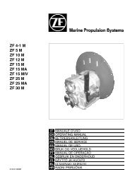
REPAIR REPAIR MANUAL MANUAL AND AND SPARE SPARE PARTS PARTS LIST LIST<br />
R E P A I R M A N U A L<br />
<strong>ZF</strong> <strong>45</strong> C version 10; 001<br />
<strong>ZF</strong> <strong>45</strong> C - Walter version 002<br />
<strong>ZF</strong> <strong>45</strong> C - Toyota version 11; 003<br />
<strong>ZF</strong> 63 C version 07; 001<br />
<strong>ZF</strong> 88 C version 001<br />
Cod. 310.01.0056d
TABLE OF CONTENTS<br />
Repair Manual and Spare Parts List <strong>ZF</strong> <strong>45</strong>C / 63C / 88C<br />
Introduction ........................................................... 2<br />
SECTION I: GENERAL DATA .................................... 2<br />
1. Transmission Set-up ....................................... 2<br />
2. Consumable goods ......................................... 3<br />
3. Measuring Tools .............................................. 3<br />
4. Standard Tools and Fixture ............................. 3<br />
SECTION II: SPECIAL TOOLS ................................. 4<br />
SECTION III: DISASSEMBLY PREPARATION ......... 5<br />
Introduction ........................................................... 5<br />
1. Preliminary operation ...................................... 5<br />
2. Housing disassembly ...................................... 5<br />
3. Input shaft ....................................................... 8<br />
4. Forward clutch housing disassembly .............. 9<br />
SECTION IV: ASSEMBLY .......................................... 12<br />
Introduction ........................................................... 12<br />
1. Input shaft ....................................................... 12<br />
2. Housing assembly ........................................... 15<br />
3. Complementary operations ............................. 18<br />
4. Oil pump .......................................................... 21<br />
SECTION V: PLAY ADJUSTMENT ........................... 22<br />
1. Reverse clutch clearance ................................ 22<br />
2. Forward clutch clearance ................................ 23<br />
3. Input shaft play ................................................. 24<br />
4. Output shaft bearing play ................................. 25<br />
SECTION VI: TIGHTENING TORQUES ................... 26<br />
SECTION VII: FUNCTION TEST .............................. 26<br />
1. Filling up with transmission fluid ..................... 26<br />
2. Check fluid level .............................................. 26<br />
3. Function test ................................................... 27<br />
4. Shifting pressure <strong>ZF</strong> <strong>45</strong>C / 63C / 88C ............. 28<br />
5. Lube oil delivery <strong>ZF</strong> <strong>45</strong>C / 63C / 88C .............. 29<br />
SECTION VIII: TROUBLESHOOTING...................... 30<br />
SECTION IX: AUTOMATIC TRANSMISSION<br />
FLUID .................................................. 33<br />
SECTION X: SPARE PARTS LIST AND<br />
EXPLOSION DRAWINGS .................... 35<br />
1
INTRODUCTION<br />
This manual gives specific instructions for the proper repair<br />
on <strong>ZF</strong> <strong>45</strong>C / 63C / 88C model transmissions.<br />
Please follow the procedures carefully to insure quality<br />
service.<br />
<strong>ZF</strong> HURTH MARINE recommends to read the manual<br />
completely before starting with repairs, as some of the<br />
procedures described are rather complex.<br />
Along with standard tools, <strong>ZF</strong> HURTH MARINE<br />
recommends the use of special tools, necessary to perform<br />
repairs correctly. The special tools are available trough<br />
your local <strong>ZF</strong> HURTH MARINE dealer.<br />
This manual is based on the technical information at the<br />
time of printing. The manual has been checked carefully in<br />
order to avoid errors. However <strong>ZF</strong> HURTH MARINE is not<br />
liable, for any misrepresentations, errors of description or<br />
omissions.<br />
Modifications on future manuals may be introduced without<br />
prior notice.<br />
The following international symbols are used in this service<br />
manual.<br />
2<br />
WARNING: THIS SYMBOL WARNS OF POSSIBLE<br />
PERSONAL INJURY.<br />
CAUTION: This symbol warns of possible damage<br />
to transmission.<br />
1.1<br />
Repair Manual and Spare Parts List <strong>ZF</strong> <strong>45</strong>C / 63C / 88C<br />
2.1<br />
1.3<br />
SECTION I: GENERAL DATA<br />
1. TRANSMISSIONS SET-UP<br />
The main components of the HSW Marine Transmissions<br />
are:<br />
Item 1 two-piece aluminum die cast<br />
1.1 oil filter<br />
1.2 oil dipstick<br />
1.3 pump<br />
Item 2 gears<br />
2.1 input shaft with forward clutch<br />
pack assembly<br />
2.2 planet gear carrier assembly<br />
Item 3 control valve<br />
1.2<br />
3<br />
2.2<br />
1
2. CONSUMABLE GOODS<br />
Repair Manual and Spare Parts List <strong>ZF</strong> <strong>45</strong>C / 63C / 88C<br />
For cleaning:<br />
Cold cleaner such as benzine, trichloroethane or Loctite<br />
fast cleaner No. 7063.<br />
WARNING<br />
Keep detergents away from your skin, do not drink and<br />
do not inhale their vapors! Always wear protective<br />
gloves and safety glasses!<br />
Note accident prevention rules!<br />
For assembly:<br />
• Loctite 2<strong>45</strong> for securing output flange on spline<br />
• Loctite 574 on the outside diameter of the seals and on<br />
mating surfaces<br />
• Grease: Klüber STABURAGS NBU 30, for radial shaft<br />
seals<br />
• ATF Fluid - 1.75 Liters (1.85 US qts)<br />
[see ATF fluid list chap. IX]<br />
3. MEASURING TOOLS<br />
Dial indicator gauge with arm-type support<br />
Range 0 - 1" (0 - 25 mm) in 0.0005" (0.01 mm) increments<br />
Caliper<br />
Range 0 - 6" (0 - 150 mm) in 0.0005" (0.01 mm) increments<br />
1/2" tool bar<br />
working edge within 0.0002" per 12"<br />
4. STANDARD TOOLS AND FIXTURE<br />
Wrench<br />
for hexagon bolts (8 mm, 13 mm, 14 mm, 17 mm, 19 mm,<br />
22 mm)<br />
Allen wrench<br />
(5 mm, 6 mm, 8 mm)<br />
Hexagon drive socket wrench<br />
(13 mm, 17 mm, 19 mm)<br />
Torque wrenches<br />
Ranges:<br />
-20 lb in -200 lb in (5 Nm - 65Nm)<br />
-15 lb ft - 100 lb ft (30 Nm - 150 Nm)<br />
Plastic hammer (1000 g) (24 oz)<br />
sturdy screwdriver<br />
- Pullers<br />
blind hole bushing (planetary gear assembly) range 1/4" to<br />
1 3/4" 4 lb slide hammer<br />
output flange range 3 1/2" to 5 1/2" 5 ton; 3 - jaw<br />
No. 2 Pry bars<br />
1/2" stock<br />
Snap ring pliers<br />
sizes: 9" (shaft diameter 1 1/2" to 3 1/2")<br />
10" (bore diameter 1 1/2" to 4")<br />
3
SECTION II: SPECIAL TOOLS<br />
It is assumed that all standard tools, such as, torque<br />
wrenches, open-end wrenches, Allen Keys and extractors,<br />
are available.<br />
All fixtures for pressing in and out should be used in<br />
conjunction with a hydraulic or manual press. Ident numbers<br />
are also stock reference numbers.<br />
Mandrel<br />
Oil pump seal, (Id. No. 500493)<br />
P/N 978.<strong>45</strong>.0022.0<br />
Mandrel<br />
Bushing, (Id. No. 500494)<br />
P/N 978.<strong>45</strong>.0023.0<br />
Mandrel<br />
Control valve oil seal, (Id. No. 500495)<br />
P/N 978.<strong>45</strong>.0024.0<br />
Mandrel<br />
Input shaft rollers bearing, (Id. No. 500496)<br />
P/N 978.<strong>45</strong>.0025.0<br />
Mandrel<br />
Forward clutch circlip, (Id. No. 500497)<br />
P/N 978.<strong>45</strong>.0026.0<br />
4<br />
Repair Manual and Spare Parts List <strong>ZF</strong> <strong>45</strong>C / 63C / 88C<br />
Mandrel<br />
Input shaft ball bearing (Id. No. 500498)<br />
P/N 978.<strong>45</strong>.0027.0<br />
Mandrel<br />
Output shaft ball bearing, (Id. No. 500499)<br />
P/N 978.<strong>45</strong>.0028.0<br />
Plate<br />
Housing support, (Id. No. 500500)<br />
P/N 978.<strong>45</strong>.0029.0<br />
Plug<br />
Forward clutch, (Id. No. 500501)<br />
P/N 978.<strong>45</strong>.0030.0<br />
Wrench<br />
Output flange, (Id. No. 500446)<br />
P/N 978.40.0002.0<br />
Antirotation bracket<br />
Output flange, (Id. No. 500502)<br />
P/N 978.<strong>45</strong>.0031.0<br />
Clamp ring<br />
Input shaft play, (Id. No. 618582)<br />
P/N 219.354.3
Repair Manual and Spare Parts List <strong>ZF</strong> <strong>45</strong>C / 63C / 88C<br />
SECTION III: DISASSEMBLY<br />
PREPARATION<br />
INTRODUCTION<br />
Clean the transmission thoroughly on the outside before<br />
disassembly.<br />
The repair area should be clean and well lighted.<br />
<strong>ZF</strong> HURTH MARINE recommends using a stand (P.N.<br />
500500) for aiding in assembly and disassembly.<br />
1. PRELIMINARY OPERATION<br />
1.1 Remove the breather valve (22) and oil dipstick (26).<br />
Clean the breather with suitable cleaner, allow to dry<br />
and coat with oil.<br />
1.2 Screw off bolts (6) and washers (10), remove the filter<br />
cover (5), seal (4) and filter element (3). Inspect seal for<br />
wear and replace if necessary. Clean the filter element<br />
with suitable cleaner.<br />
WARNING<br />
Position a container to pick up the oil flow.<br />
2. HOUSING DISASSEMBLY<br />
2.1 Position the marine gearbox on the housing support<br />
(P.N. 500500).<br />
2.2 Screw off bolts (6) and washers (10). Remove the<br />
pump cover assembly (34). Inspect sealing ring (1) and<br />
O-Ring (33); inspect for wear and replace if necessary.<br />
2.3 Remove the rotor pump from the shaft. If it needs to be<br />
replaced, the complete cover assembly (34) has to be<br />
replaced.<br />
NOTE: Pump gear should be installed the same side down<br />
as removed.<br />
5
2.4 Using pliers remove the key (28) from shaft.<br />
NOTE: Take note of the position of the key.<br />
2.5 Screw off bolts (7), (8) and washers (10).<br />
2.6 By tapping with a soft hammer separate the cover (35)<br />
from the housing (36).<br />
6<br />
Repair Manual and Spare Parts List <strong>ZF</strong> <strong>45</strong>C / 63C / 88C<br />
2.7 Remove the cover (35).<br />
2.8 Remove reverse clutch first outer disc (63).<br />
2.9 Remove springs (58).
Repair Manual and Spare Parts List <strong>ZF</strong> <strong>45</strong>C / 63C / 88C<br />
2.10 Remove inner disc (62), outer disc (63), inner disc<br />
(62), the last outer disc (63) and if present shims<br />
(64),(65).<br />
2.11 Pull out the shaft and forward clutch assembly.<br />
2.12 Remove thrust washer (<strong>45</strong>) which is remained on the<br />
planet gear carrier assembly and (with standard puller)<br />
bushing (46).<br />
2.13 Turn the housing upside down. Using the tool<br />
P.N.500446 loosen nut (72); stop the output flange<br />
(66) from turning using tool P.N.500502. Discard O-<br />
Ring (71) and replace with a new one.<br />
2.14 Remove flange using appropriate puller.<br />
[see type page 3].<br />
WARNING<br />
2.15 With a soft hammer disassemble the output shaft.<br />
Driving it out from the housing.<br />
7
2.16 Don't disassemble the output shaft.<br />
If it's necessary to replace it, ask for complete gear<br />
carrier assembly (38).<br />
3. INPUT SHAFT<br />
3.1 Remove piston rings (39) from the input shaft (37).<br />
3.2 Remove spacer (42b), needle bearing (42a), other<br />
spacer (42b) and shims (75-76).<br />
8<br />
Repair Manual and Spare Parts List <strong>ZF</strong> <strong>45</strong>C / 63C / 88C<br />
3.3 With pliers remove the circlip (44).<br />
NOTE: Take note of the position of the circlip (44).<br />
3.4 Support the ring gear allowing room for the input shaft<br />
with gears to come out bottom side.<br />
NOTE: Pressing on splined end of shaft disassemble it<br />
from the clutch housing.<br />
This operation will damage the bearing.<br />
Use a press with:<br />
distance: 200 mm (8 inches)<br />
min. force: 2000 kg (4400 lbs)<br />
3.5 Remove piston rings (40) from the input shaft (37).
Repair Manual and Spare Parts List <strong>ZF</strong> <strong>45</strong>C / 63C / 88C<br />
4. FORWARD CLUTCH HOUSING<br />
DISASSEMBLY<br />
4.1 Remove circlip (48).<br />
WARNING<br />
4.2 With a screwdriver remove the circlip (50).<br />
4.3 Support clutch housing flat on to a work bench. Separate<br />
ring gear support (47) from the ring gear (49).<br />
4.4 Remove forward clutch inner (60), outer (61) shims<br />
(73) (74) and end disc (59).<br />
WARNING<br />
4.5 Remove circlip (55), cup springs (54).<br />
Remove only if defective.<br />
4.6 With a tool P.N.500498 drive out ball bearing (43) which<br />
has to be discarded and replaced with a new one.<br />
4.7 Introduce air with tool P.N. 500501 to push out the<br />
piston (51).<br />
The piston can also be removed by gently tapping on<br />
the outer diameter of the housing with a soft hammer.<br />
51<br />
500501<br />
47<br />
9
4.8 Remove O-Rings (52), (53) from the piston (51).<br />
10<br />
WARNING<br />
4.9 Inject air through the indicated hole, to remove the<br />
piston (56). The hole is located on the upper circular<br />
surface of the housing cover (clutch piston side) just<br />
under the piston screw (18).<br />
4.10 Remove the O-Ring (33) from cover (35).<br />
Repair Manual and Spare Parts List <strong>ZF</strong> <strong>45</strong>C / 63C / 88C<br />
4.11 Remove O-Rings (57) from piston (56).<br />
NOTE: Replace O-Rings (33, 57) if disassembled.<br />
4.12 Remove the stop screw (17) and position screw (18),<br />
the two washers (13), the spring (20) and the ball (21).<br />
13<br />
17<br />
13<br />
18<br />
4.13 Remove the neutral safety switch (15), the plugs (12,<br />
14), spacer (16), ball (21) and washer (19).<br />
4.14 Using two screwdrivers pull out the distributor shaft<br />
(24), the distributor shaft seal (23) will come out<br />
together.<br />
Remove seal ring (23) from the spool valve (24).<br />
NOTE: 1 - Take note of the position of the seal ring.<br />
2 - Replaced the seal ring if disassembled.<br />
CAUTION<br />
Don't disassemble the distributor shaft (24), if it's<br />
necessary to replace it use the complete group.
Repair Manual and Spare Parts List <strong>ZF</strong> <strong>45</strong>C / 63C / 88C<br />
4.15 By striking with a soft hammer remove needle bearing (41).<br />
Only if bearing is defective.<br />
To do it properly support the cover allowing room for the<br />
needle bearing to come out bottom side. Stick a screw<br />
driver/punch into the internal edge of the cage and tap<br />
gently with a soft hammer in a criss cross pattern.<br />
NOTE: This operation will damage the bearing.<br />
WARNING<br />
The improper use of screwdriver / punch can damage<br />
the cover. After having removed the bearing check for<br />
scratches on the cover.<br />
4.16 Remove sealing ring (1) and O-Ring (33) from pump<br />
cover (34).<br />
NOTE: This operation will damage the sealing ring.<br />
Take note of the position of the seal ring.<br />
4.17 Remove baffle (29).<br />
With a screwdriver take out an end of the baffle from<br />
the groove on the housing.<br />
By gripping and rolling up the baffle take it out from the<br />
housing.<br />
NOTE: <strong>ZF</strong> <strong>45</strong>C VERS. TOYOTA 11 ONLY<br />
Two additional baffles (30) and (31) and pin spacer (32) are<br />
present.<br />
4.18 Remove output sealing ring (2).<br />
NOTE: This operation will damage the oil seal.<br />
4.19 Remove circlip (70).<br />
11
4.20 Support housing (36) flat on a press, press out bearing<br />
(67), then remove shims (68) (69).<br />
NOTE: This operation will damage the bearing.<br />
12<br />
67<br />
SECTION IV: ASSEMBLY<br />
INTRODUCTION<br />
A well-lighted work area that is free from dirt and chips, will<br />
facilitate the work considerably.<br />
<strong>ZF</strong> HURTH MARINE recommends to use a swivelling<br />
stand, described in the disassembly section to aid in the<br />
assembly.<br />
Thoroughly clean all mating surfaces from any loctite or<br />
gasket material.<br />
WARNING<br />
Cleaners and solvents can be toxic and harmful without<br />
proper ventilation.<br />
Use caution when using such cleaners.<br />
Always wear protective gloves and glasses!<br />
The next assembly procedure requires the following:<br />
• A hydraulic or mechanical press.<br />
Repair Manual and Spare Parts List <strong>ZF</strong> <strong>45</strong>C / 63C / 88C<br />
Tool<br />
36<br />
1. INPUT SHAFT<br />
1.1 Install O-Rings (52) (53) on the piston (51). Insert the<br />
piston into the input bell (47).<br />
NOTE: Wet the O-Rings with ATF.<br />
Wet the mating surfaces with ATF.<br />
Complete the assembly with a soft hammer.<br />
WARNING<br />
1.2 Position cup springs (54) as shown in figure.<br />
First cup spring has to be installed with the bigger<br />
diameter against the piston.<br />
Second and third cup springs have to be installed in<br />
succession with their bigger diameters against each<br />
other.<br />
51 54<br />
35
1.3 Position the circlip (55).<br />
Repair Manual and Spare Parts List <strong>ZF</strong> <strong>45</strong>C / 63C / 88C<br />
1.4 With tool P.N. 500497 compress the cup springs.<br />
Be sure of their aligment.<br />
1.5 Install the piston rings (40).<br />
NOTE: Coat sealing rings with grease or Petroleum Jally.<br />
1.6 Insert end disc (finished side up) (59), shims (73 - 74)<br />
and alternatively outer clutch disc (61) and inner<br />
clutch disc (60).<br />
NOTE: To set correct play see item 2 page 23.<br />
Clutch discs have to be coated with ATF.<br />
1.7 With tool p.n. 500498 and a suitable support press the<br />
ball bearing (43) into the ring gear support (47).<br />
1.8 Insert the circlip (48).<br />
WARNING<br />
Be sure that snap ring has been properly seated (check<br />
circlip opening to be not close to slots in clutch housing).<br />
13
1.9 Press the forward clutch housing (47) on the input shaft<br />
(37).<br />
1.10 Install the circlip (44).<br />
NOTE: Check carefully correct position of the circlip (44).<br />
1.11 Turn up side down the ring gear (49) and place it on<br />
a suitable support, allowing the shaft go down<br />
completely.<br />
Insert the input shaft (37) into the ring gear (49)<br />
allowing the inner clutch discs to be driven by the disc<br />
carrier.<br />
14<br />
Repair Manual and Spare Parts List <strong>ZF</strong> <strong>45</strong>C / 63C / 88C<br />
1.12 Install the circlip (50).<br />
WARNING<br />
Be sure that snap ring has been properly seated (check<br />
circlip opening to be not close to slots in clutch housing).<br />
1.13 Install onto input shaft (37) the seal rings (39).<br />
NOTE: Install seal rings (39) with openings in opposite<br />
positions.<br />
1.14 Insert shims (75, 76) between circlip (48) and thrust<br />
washer (42).<br />
NOTE: To set correct play see item 3 pag. 24.
Repair Manual and Spare Parts List <strong>ZF</strong> <strong>45</strong>C / 63C / 88C<br />
1.15 With toll P.N. 500499 and a suitable support press ball<br />
bearing (67).<br />
Add shims (68, 69) max bearing play:<br />
0,1 mm (0.0039 in)<br />
NOTE: To set correct play see item 4 page 25.<br />
1.16 Install snap ring (70).<br />
2. HOUSING ASSEMBLY<br />
2.1 With tool P.N. 500499 install sealing ring (2).<br />
NOTE:<br />
- Use Loctite P.N. 574 between housing and sealing ring.<br />
- Fill internal lips of sealing ring with high quality grease (for<br />
ex. Klüber STABURAGS NBU 30).<br />
2.2 Insert the baffle (29) as shown in the picture. The fold<br />
of the baffle must correspond with the groove on the<br />
housing opposite to the breather position on the second<br />
fold into the same slot. The baffle must be straight and<br />
tight up against the under side of the housing.<br />
NOTE: <strong>ZF</strong> <strong>45</strong>C vers. TOYOTA 11 only<br />
Install additional baffles (30, 31) and pin spacer (32).<br />
2.3 With special tool P.N. 500496 install needle bearing<br />
(41) into the cover (35).<br />
2.4 Install O-Rings (33) into the cover (35).<br />
15
2.5 Install O-Ring (57) into the piston (56).<br />
Wet O-Ring with ATF oil and using a plastic hammer,<br />
install the assembled piston (56) into cover (35).<br />
2.6 Install the filter (3).<br />
2.7 Install the rubber oil plate (4).<br />
16<br />
Repair Manual and Spare Parts List <strong>ZF</strong> <strong>45</strong>C / 63C / 88C<br />
2.8 Assemble the cover (5).<br />
Tights bolts (6) with washer (10). Tightening torque: 18<br />
Nm (13.3 lb ft.).<br />
2.9 Install spool valve (24) onto front cover (35) cheking for<br />
the correct alignement of groove.<br />
2.10 Install stop screw (17) with washer (13) Tightening<br />
torque: 12 Nm (8.9 lb ft.).<br />
Install onto cover (35) ball (21), spring (20) and guide<br />
spring (18) together with sealing washer (13).<br />
Guide spring (18) tightening torque: 12 Nm (8.9 lb ft.).<br />
Turn slowly spool valve (24) to centre groove to ball<br />
(21).<br />
NOTE: The plug shown in the figure with the arrow, will only<br />
be tighten if the distributor is correctly oriented.
Repair Manual and Spare Parts List <strong>ZF</strong> <strong>45</strong>C / 63C / 88C<br />
2.11 Install bushing (16) in the way that its bigger diameter<br />
is up.<br />
2.12 Install the ball (21).<br />
2.13 Install the microswitch (15).<br />
2.14 Install plug (14) and washer (19).<br />
NOTE: Tighten to 25 Nm (18.5 lb ft.) torque.<br />
2.15 Install sealing ring (23) using the special tool P.N.<br />
500495 and a plastic hammer.<br />
NOTE: Check the correct position of sealing ring (23).<br />
2.16 Install the lever (25) with bolt (11) washer (10) and<br />
nut (9).<br />
NOTE: Tigthen bolt (11) to 22.5 Nm. (16.5 lb ft.) torque.<br />
17
Neutral Safety Switch Function check<br />
Connect neutral safety switch with a lamp in series to a<br />
battery. The neutral safety switch operates when the lamp<br />
is lighted.<br />
NOTE: The lamp must be extinguised when the pin is<br />
pushed in.<br />
18<br />
Battery 14 V DC<br />
Battery 14 V DC<br />
3. COMPLEMENTARY OPERATIONS<br />
3.1 Install the friction bearing (46) with tool P.N. 500494.<br />
3.2 Assemble the output shaft by pressing the shaft into<br />
the housing.<br />
NOTE: Coat output shaft with grease prior to assembly.<br />
As a precaution support the inner race of the bearing.<br />
Repair Manual and Spare Parts List <strong>ZF</strong> <strong>45</strong>C / 63C / 88C<br />
Lamp 8.4 A<br />
Lamp 8.4 A<br />
Neutral<br />
position<br />
A or B<br />
position<br />
3.3 Install the thrust washer (<strong>45</strong>).<br />
CAUTION<br />
Be sure the bend correspond with the hole.<br />
<strong>45</strong><br />
3.4 Assemble the input shaft assembly into the housing.<br />
NOTE: To set correct play see item 3 page 23.
3.5 Install reverse clutch pack.<br />
Insert shims (64, 65).<br />
Install the first outer disc (63).<br />
Repair Manual and Spare Parts List <strong>ZF</strong> <strong>45</strong>C / 63C / 88C<br />
NOTE: To set correct play see item 3 pag. 24.<br />
3.6 Install inner disc (62), outer disc (63) and inner disc<br />
(62).<br />
3.7 Spread front housing (36) with LOCTITE 574.<br />
NOTE: Check that Loctite sealant covers the mating surface<br />
around the holes.<br />
3.8 Install springs (58).<br />
3.9 Install the final outer disc (63).<br />
CAUTION<br />
The last external disc (63) must cover the springs (see<br />
picture).<br />
The first installed two outer discs (63) must have the four<br />
grooves in connection with the four housing springs. The<br />
last installed disc (63) must have the four grooves in<br />
connection with the four housing studs. The last outer disc<br />
is consequently installed upside-down compared to the first<br />
ones.<br />
3.10 Coat sealing ring (39) with grease (for ex. POLYLUB<br />
GA 352 P).<br />
19
3.11 Assemble the cover down over the input shaft.<br />
NOTE: Be sure of the correct position of the outer disc (63)<br />
when pressing the cover against the housing.<br />
3.12 Install screws (7, 8) with washers (10).<br />
NOTE: Tighten them to 18Nm (13.3 lb ft.) torque.<br />
Tighten the screws evenly to avoid binding the housing on<br />
the shaft.<br />
3.13 Install the output flange (66).<br />
NOTE: Use LOCTITE 2<strong>45</strong> on the spline between output<br />
shaft and output flange.<br />
20<br />
Repair Manual and Spare Parts List <strong>ZF</strong> <strong>45</strong>C / 63C / 88C<br />
3.14 Wet O-ring (71) with grease.<br />
3.15 Tighten the output shaft ring nut (72). Use tool P.N.<br />
500446 and P.N. 500502.<br />
NOTE: Tighten the ring nut (72) to 120Nm (88 lb ft.) torque.<br />
3.16 Install the breather (22) using LOCTITE 574 and the<br />
oil dipstick (26) together with O- Ring (27).
4. OIL PUMP<br />
Repair Manual and Spare Parts List <strong>ZF</strong> <strong>45</strong>C / 63C / 88C<br />
4.1 Install onto shaft (37) key (28) driving inner pump gear.<br />
NOTE: Check carefully correct position of key (28).<br />
4.2 Install onto input shaft (37) the inner pump gear.<br />
NOTE: Pump gear must be positioned in the way that the<br />
rounded groove alligned with the driving key (28).<br />
4.3 Spread out external diameter of sealing ring (1) with<br />
LOCTITE 574 and lips with grease (for ex. Klüber<br />
STABURAGS NBU 30).<br />
With tool P.N. 500493 and suitable support press input<br />
shaft seal (1) into the oil pump cover (34).<br />
NOTE: Check for correct position of sealing ring (1).<br />
4.4 Wet O-Ring (33) with ATF fluid and install it into the<br />
pump cover.<br />
4.5 Install the external gear into the oil pump cover.<br />
4.6 Install pump cover assembly.<br />
NOTE: Be sure to properly index the arrow to point in the<br />
same direction as the engine rotates.<br />
21
4.7 Install cover.<br />
NOTE: Tighten the screws to 18 Nm. (13.3 lb ft.) torque in<br />
a criss cross pattern.<br />
WARNING<br />
The necessary time for a complete polymerization is 5<br />
hours: we recommend therefore to clean carefully the<br />
mating surfaces with Loctite 7063. Cleaner before<br />
applying the Loctite 518 and wait the requested time<br />
before the spin test.<br />
SECTION V: PLAY ADJUSTMENT<br />
1. REVERSE CLUTCH CLEARANCE<br />
NOTE: ONLY FOR MEASUREMENT THE LAST DISC<br />
(63) HAS TO BE INSTALLED IN THE SAME WAY AS THE<br />
OTHER ONES [NOT AGAINST THE SPRINGS (58)<br />
22<br />
Fig. V1<br />
Repair Manual and Spare Parts List <strong>ZF</strong> <strong>45</strong>C / 63C / 88C<br />
Fig. V2<br />
1) Install reverse clutch pack into housing:<br />
3x external clutch discs p/n 3311 301 006 plus 2x<br />
internal clutch discs p/n 3311 302 027.<br />
2) Take measurement "A" (See fig. no. V1).<br />
For example: "A" = 10.10 mm
Repair Manual and Spare Parts List <strong>ZF</strong> <strong>45</strong>C / 63C / 88C<br />
3) Take measurement "B" (See fig. no. V2).<br />
For example: "B" = 9.66 mm<br />
4) Select proper tickness shims to set the gap "R".<br />
Shims available:<br />
Shim 0.3 mm p/n 3311 301 042<br />
Shim 0.5 mm p/n 3311 301 043<br />
"R" = "A" – "B"<br />
For example: "R" = 0.44 mm<br />
"R" must be from 0,016" to 0,020" (0.40 mm to 0.50 mm)<br />
2. FORWARD CLUTCH CLEARANCE<br />
Fig. V3<br />
1) Install end disc p/n 3311 302 034 in ring gear p/n 3311 302 026.<br />
2) Install snap ring p/n 0630 513 066 in ring gear.<br />
3) Set 0.00 mm of the caliper on the snap ring.<br />
Caliper<br />
Set 0.00 mm<br />
23
4) Take measurement "A" in different points and make the<br />
average.<br />
For example: "A" = 48.53 mm<br />
5) Remove snap ring p/n 0630 513 066 and measure its<br />
tickness "B".<br />
For example: "B" = 2.46 mm<br />
6) Take measurement "C" on forward clutch housing<br />
assembly in different points and make the average.<br />
For example: "C" = 22.90 mm<br />
7) Take measurement "E" of the clutch pack (6x external<br />
clutch discs p/n 3311 302 029 plus 5x internal clutch<br />
discs p/n 3311 302 028) in different points and make<br />
the average.<br />
24<br />
Repair Manual and Spare Parts List <strong>ZF</strong> <strong>45</strong>C / 63C / 88C<br />
For example: "E" = 22.55 mm<br />
8) Select proper tickness shims to set the gap "F".<br />
Shims available:<br />
Shim 0.2 mm p/n 0630 004 229<br />
Shim 0.3 mm p/n 0630 004 124<br />
For example: "F" = 0.62 mm<br />
3. INPUT SHAFT PLAY<br />
Install input shaft assembly in housing assembly.<br />
Install shims (75) (76), spacer (42b) needle bearing (42a)<br />
and other spacer.<br />
Take measurement "L" between spacer (42b) and housing<br />
(36) mating surface.<br />
Use a tool bar and a standard caliper.<br />
(as shown in figure in figure V4).<br />
Fig. V4<br />
"F" = "A" – "B" – "C" – "E"<br />
"F" must be from 0,018" to 0,022" (0.<strong>45</strong> mm to 0.55 mm)
Repair Manual and Spare Parts List <strong>ZF</strong> <strong>45</strong>C / 63C / 88C<br />
Take measurement "M" between cover (35) mating surface<br />
and the surface shown on figure V5.<br />
Select proper thickness shims (75) (76) to set the gap "I".<br />
Fig. V5<br />
Fig. V6<br />
"I" = 0.008" to 0.02"<br />
(0.2 mm to 0.5 mm)<br />
"I" = "M" - "L"<br />
WARNING<br />
To check the play, once the gearbox is assembled, use<br />
tool clamp ring P.N. 618582, as shown in figure V6.<br />
CAUTION<br />
Set down to the housing the input shaft and measure<br />
with a dial indicator the play "I" moving the input shaft<br />
with the aid of two prybars.<br />
4. OUTPUT SHAFT BEARING PLAY<br />
This measurement has to be taken only is housing (36) is<br />
replaced.<br />
Install snap ring (70) in housing (36).<br />
Take measurement "S" as shown in picture V7.<br />
Remove snap ring (70) and measure its thickness "V".<br />
Measure width "R" of the bearing.<br />
Select proper thickness shims (68) (69) to set maximum<br />
play "Z"<br />
Fig. V7<br />
"Z" = "S" - "V" - "Q"<br />
"Z" = 0,004" (0.1 mm)<br />
25
SECTION VI: TIGHTENING TORQUES<br />
SECTION VII: FUNCTION TEST<br />
1. FILLING UP WITH TRANSMISSION FLUID<br />
Filling with ATF fluid into the dipstick opening.<br />
Quantity:<br />
<strong>ZF</strong> <strong>45</strong>C vers. 10,001: 2.1 US-qts (2,0 liters)<br />
<strong>ZF</strong> <strong>45</strong>C Walter vers. 002: 2.1 US-qts (2,0 liters)<br />
<strong>ZF</strong> <strong>45</strong>C Toyota vers. 11,003: 1.7 US-qts (1,6 liters)<br />
<strong>ZF</strong> 63C vers. 07,001: 2.1 US-qts (2,0 liters)<br />
<strong>ZF</strong> 88C vers. 001: 2.1 US-qts (2,0 liters)<br />
ATF (Automatic Transmission Fluid) such as, per list on<br />
section IX.<br />
2. CHECK FLUID LEVEL<br />
Carry out a trial run after oil filling.<br />
Set shifting lever to neutral position (N). Start engine and let<br />
it run idle for a short time to fill the cooler and pipelines with<br />
transmission oil. Stop the engine and check oil level again.<br />
26<br />
Repair Manual and Spare Parts List <strong>ZF</strong> <strong>45</strong>C / 63C / 88C<br />
Part Size Torque in Nm Torque in lb ft.<br />
Housing bolts M8 18 Nm 13 lb ft.<br />
Oil pump bolts M8 18 Nm 13 lb ft.<br />
Plate oil filter M8 18 Nm 13 lb ft.<br />
Distributor lever M8 23 Nm 17 lb ft.<br />
Output flange ring nut M32x1.5 120 Nm 88 lb ft.<br />
Breather filter (with Loctite n° 574) - Hand tight Hand tight<br />
Dipstick - Hand tight Hand tight<br />
Stop screw - 12 Nm 8.9 lb ft.<br />
Guide bolt - 12 Nm 8.9 lb ft.<br />
Plug 3/8 - 18 NPTF - 10 Nm 7.4 lb ft.<br />
Pressure plug - 25 Nm 18.5 lb ft.<br />
A<br />
housing<br />
If necessary, top up with oil. Excessive oil should be<br />
removed. The fluid level on the dipstick (item 1, figure B)<br />
should be between the min. end max marks. The fluid level<br />
should be checked again after a short driving period.<br />
NOTE: Some transmissions may have different oil<br />
dipsticks, depending on the version:<br />
A) When inserted into the housing hole, it expands by turning<br />
the handle in clockwise direction; (see Fig item A).<br />
B) It is threaded (See Fig. item B).<br />
IMPORTANT<br />
Oil check with threaded dipstick (B) must be done in a<br />
different way compared with the one not threaded (A).<br />
A) Oil dipstick and housing hole not threaded: dipstick<br />
completely inserted into hole.<br />
B) Oil dipstick and housing hole threaded: dipstick not<br />
inserted into the housing hole (not screw in).<br />
NOTE: Dipstick version A doesn't require any O-Ring,<br />
dipstick version B requires O-Ring. (see item 27 in<br />
explosion drawing pag. 41.<br />
1<br />
B<br />
housing
3. FUNCTION TEST<br />
Repair Manual and Spare Parts List <strong>ZF</strong> <strong>45</strong>C / 63C / 88C<br />
When the transmission has been completely assembled<br />
and filled up with transmission fluid, it would be convenient<br />
to make a function test.<br />
This test can be carried out on a bench test rig, or in a boat.<br />
If no fluid cooler can be connected, a hydraulic hose must<br />
be connected between the inlet and outlet of the hydraulic<br />
pump.<br />
Measuring instruments required<br />
• Pressure gauge 0-25 bar (0-360 psi), with connecting<br />
thread M10x1 (oil pressure gauge set with hole and<br />
adaptor is available).<br />
THE FUNCTION TEST SHOULD BE CARRIED OUT FOLLOWS:<br />
• Temperature gauge 0-120°C (0-250°F), connecting<br />
thread 3/8"-18NPSF.<br />
• Flow meter 0-35 liters/min<br />
(0-10 gals/min).<br />
Tests to be carried out:<br />
1 Fluid leaks<br />
2 Noise<br />
3 Direction of rotation, LH/RH<br />
4 Lube oil temperature<br />
5 Shifting pressure<br />
6 Lube oil flow rate<br />
Motor speed rpm Shift lever position Durat. minutes Test<br />
800-1000 neutral 5 1, 2<br />
600-800 AB position - 1, 2, 3<br />
(idling speed) repeatedly<br />
1500-2500 B position * 1, 2, 4<br />
600-800 AB position - 1, 2, 3<br />
(idling speed) repeatedly<br />
idling- max. speed A position - 1, 2, 5**, 6**<br />
600-800 A->B position - 1, 2<br />
(idling speed)<br />
idling- max. speed B position - 1, 2, 5**, 6**<br />
* Until a fluid temperature of 75-80°C (167-176° F) has been reached.<br />
** At different speeds.<br />
A = FORWARD<br />
B = REVERSE<br />
27
4. SHIFTING PRESSURE <strong>ZF</strong> <strong>45</strong>C / 63C / 88C<br />
<strong>ZF</strong> <strong>45</strong>C<br />
Max 20 bar (290 p.s.i.) at 70 °C (160 F°) and 4000 rpm.<br />
Min 14 bar (203 p.s.i.).<br />
28<br />
Shifting Pressure [bar]<br />
30<br />
20<br />
10<br />
0<br />
Repair Manual and Spare Parts List <strong>ZF</strong> <strong>45</strong>C / 63C / 88C<br />
max. <strong>45</strong>C<br />
min. <strong>45</strong>C<br />
0 1000 2000 3000 4000 5000<br />
Driving Speed [rpm]<br />
<strong>ZF</strong> 63C<br />
Max 23 bar (333.5 p.s.i.) at 70 °C (160 F°) and 4000 rpm.<br />
Min 17 bar (246.5 p.s.i.).<br />
Shifting Pressure [bar]<br />
30<br />
20<br />
10<br />
0<br />
max. 63C<br />
min. 63C<br />
0 1000 2000 3000 4000 5000<br />
Driving Speed [rpm]<br />
400<br />
350<br />
300<br />
250<br />
200<br />
[psi]<br />
150<br />
100 Pressure<br />
50<br />
0 Shifting<br />
400<br />
350<br />
300<br />
250<br />
200<br />
[psi]<br />
150<br />
100 Pressure<br />
50<br />
0 Shifting
Repair Manual and Spare Parts List <strong>ZF</strong> <strong>45</strong>C / 63C / 88C<br />
<strong>ZF</strong> 88C<br />
Max 24 bar (348 p.s.i.) at 70 °C (160 F°) and 4000 rpm.<br />
Min 19 bar (275.5 p.s.i.).<br />
Shifting Pressure [bar]<br />
5. LUBE OIL DELIVERY <strong>ZF</strong> <strong>45</strong>C / 63C / 88C<br />
Delivery Rate [l/min]<br />
30<br />
20<br />
10<br />
0<br />
0 1000 2000 3000 4000 5000<br />
Driving Speed [rpm]<br />
[Gallon/min]<br />
Rate Delivery<br />
30<br />
7.91<br />
7.39<br />
6.86<br />
6.33<br />
5.80<br />
20<br />
5.28<br />
10<br />
0<br />
4.75<br />
4.22<br />
3.69<br />
3.16<br />
2.64<br />
2.11<br />
1.58<br />
1.05<br />
0.53<br />
0<br />
0 1000 2000 3000 4000 5000<br />
Driving Speed [rpm]<br />
min.<br />
max. 88C<br />
min. 88C<br />
400<br />
350<br />
300<br />
250<br />
200<br />
[psi]<br />
150<br />
100 Pressure<br />
50<br />
0 Shifting<br />
29
SECTION VIII: TROUBLESHOOTING<br />
In case of trouble, check first whether all items of the<br />
present mounting and operating instructions have been<br />
completed with.<br />
The subsequent tables will assist you in troubleshooting<br />
and finding a remedy yourself.<br />
30<br />
Repair Manual and Spare Parts List <strong>ZF</strong> <strong>45</strong>C / 63C / 88C<br />
If any interventions are necessary on the transmission,<br />
please refer to the Repair Manual.<br />
Warranty claims will be forfeited if work on the transmission<br />
is performed by un-authorized persons during the warranty<br />
period.<br />
Syptom Possibly cause Remedy<br />
1. Transmission 1.1 Shifting lever is loose Tighten clamping bolt on<br />
cannot be shifted shifting lever<br />
1.2 Remote control does Lift remote control off, if<br />
not permit lever travel gears can be shifted by<br />
required for testing hand, correct remote control.<br />
1.3 Remote control faulty Repair remote control<br />
1.4 No shifting pressure<br />
available<br />
Refer to 7<br />
2. Delayed shift 2.1 Shift linkage Lift remote control off, if<br />
time misadjusted; gear can be shifted by hand,<br />
not allowing correct remote control.<br />
full engagement If the transmission cannot<br />
be shifted correctlyby<br />
hand, replace<br />
the control valve.<br />
2.2 Wrong clutch play Disassemble the gearbox and<br />
adjustment check forward or reverse<br />
clutch clearance.<br />
3. Clutch is slipping, 3.1 Inadmissible fluid used Drain fluid, refill with prescribed<br />
i.e.propeller speed fluid, flush transmission<br />
too low as compared while engine runs<br />
to engine speed in neutral position, drain<br />
fluid, refill transmission.<br />
3.2 Fluid contains water Refer to 9<br />
3.3 Shifting pressure too low Refer to 6<br />
3.4 Wear on clutch discs Disassemble transmission,<br />
replace clutch discs<br />
3.5 Piston rings in clutch are Disassemble transmission,<br />
damaged replace piston rings<br />
4. Transmission 4.1 Medium piston ring in Replace piston ring.<br />
locked input shaft in control<br />
block is faulty.<br />
4.2 Warped discs due to<br />
overheating of slipping<br />
clutch<br />
Refer to 3<br />
4.3 Needle bearings on Disassembly transmission and<br />
input shaft are worn out repair.<br />
4.4 Pump gear is worn Disassemble transmission<br />
and repair<br />
5. Output shaft turns in 5.1 Rotary slide valve in Replace control valve<br />
neutral position control valve is worn<br />
5.2 Faulty needle bearing Disassemlby transmission<br />
on input shaft and input shaft, replace<br />
bearing concerned and<br />
other damaged parts<br />
5.3 Warped discs due to<br />
overheating of slipping<br />
clutch<br />
Refer to 3
Repair Manual and Spare Parts List <strong>ZF</strong> <strong>45</strong>C / 63C / 88C<br />
Syptom Possibly cause Remedy<br />
6. Shifting pressure 6.1 Fluid filter clogged Clean or replace fine filter<br />
too low 6.2 Fluid level in transmission Top-up with fluid; in case<br />
too low. of fluid loss check transmission,<br />
cooler and pipelines<br />
for leakage and remedy<br />
same; also refer to 10.<br />
through 13.<br />
6.3 Fluid pump is worn out Replace cover<br />
containing fluid pump<br />
6.4 Spring in shifting pressure<br />
relief valve is broken<br />
Replace control valve<br />
6.5 Piston rings on input Replace piston rings. In case<br />
shaft are faulty of wear due to faulty piston<br />
rings replace housing cover<br />
as well<br />
6.6 O-rings in clutch Disassemble transmission,<br />
are faulty replace clutch O-rings<br />
7. No shifting pressure 7.1 Direction of engine rotation Rotate pump assy. of 180 °<br />
available does not agree with<br />
arrow on transmission<br />
7.2 No fluid in the transmission Refill with fluid<br />
7.3 Fine filter is dirty Clean or replace fine filter<br />
7.4 Fluid level in transmission Top-up with fluid. In case of<br />
is too low loss of fluid check transmission,<br />
cooler and pipelines<br />
for leakage and remedy<br />
same, also refer to 10.<br />
through 13.<br />
7.5 Fluid pump worn out Replace pump cover and pump<br />
7.6 Fitting key in input shaft Remove control block.<br />
for fluid pump drive is Replace fitting key, replace<br />
broken any other faulty parts<br />
8. Excessive fluid 8.1 Fluid cooler is too small Use a larger fluid cooler<br />
temperature 8.2 Excessive fluid in transmission Remove excessive fluid<br />
8.3 Fluid cooler is dirty on Detach coolant water lines<br />
water side and clean fluid cooler<br />
on water side<br />
8.4 Worn fluid pump in Replace cover<br />
transmission taining fluid pump<br />
8.5 Faulty piston rings in<br />
input shaft<br />
Replace piston rings.<br />
8.6 Clutch is slipping Refer to 3.<br />
8.7 Clutch does not open Dismount transmission and<br />
completely due to worn coupling, replace all faulty<br />
disc support parts<br />
8.8 With fluid cooler in bypass<br />
and unfavorable<br />
arrangement of pipelines<br />
too little coolant waterflows<br />
through bypass to<br />
cooler<br />
Correct bypass pipeline<br />
9. Water in the fluid, 9.1 Fluid cooler faulty Repair leakage at cooler or<br />
fluid looks milky replace cooler. Change<br />
transmission fluid<br />
9.2 High water level in Remedy cause for water<br />
engine compartment, level in engine compartment<br />
water entering through<br />
output shaft seal or<br />
breather.<br />
change transmission fluid.<br />
10. Fluid leakage at 10.1 Breather clogged with paint or dirt Remove paint or dirt from breather<br />
output shaft 10.2 Shaft seal faulty Disassemble transmission, replace seal.<br />
31
32<br />
Repair Manual and Spare Parts List <strong>ZF</strong> <strong>45</strong>C / 63C / 88C<br />
Syptom Possibly cause Remedy<br />
11. Fluid leakage at 11.1 Excessive fluid in Pump excessive fluid out<br />
breather transmission with commercial hand pump<br />
12. Fluid leakage at 12.1 Bolts are not tight Tighten bolts with prescribe<br />
joints torque.<br />
12.2 Seals on bolts have Replace seals, tighten bolts<br />
used several times with prescribed torque<br />
12.3 Mating faces are Unscrew housing half, finish<br />
contaminated, no surface mating faces with oilstone<br />
seal applied or finishing file, apply surface seal.<br />
Assemble transmission, tighten bolts<br />
with correct torque.<br />
13. Transmission noise 13.1 Fluid level too low so Top up with fluid to<br />
becomes louder that pump sucks in air. marking on dipstick.<br />
13.2 Damage starting on Replace flexible coupling.<br />
flexible coupling due to Check alignment between<br />
wear or fatigue, possible<br />
due to misalignment<br />
between engine and<br />
transmission.<br />
engine and transmission.<br />
13.3 Beginning damage of Disassemble transmission,<br />
bearings in transmission, replace bearings concerned<br />
e.g. due to torsional and other faulty parts. Find<br />
vibrations, running without<br />
fluid, overload,<br />
wrong alignment of<br />
transmission excessive<br />
engine output<br />
causes and remedy.<br />
13.4 Beginning damage of Disassemble transmission,<br />
gearings, e.g. due to<br />
torsional vibrations,<br />
running without fluid,<br />
overload<br />
remove faulty parts.<br />
13.5 Dirty fine filter Clean or replace fine filter<br />
14. Chattering 14.1 The engine or propeller Mount a flexible coupling<br />
transmission noise generate torsional with another stiffness<br />
mainly at low engine vibrations in the drive factor between engine and<br />
speed unit which produce a transmission; a coupling<br />
“chattering” noise in the with a higher stiffness<br />
transmission factor might be sufficient.<br />
Otherwise analyse the<br />
torsional vibrations to find<br />
out the required stiffness<br />
for the coupling.<br />
14.2 Misaligned propeller Mount and align propeller<br />
shaft on output shaft strictly according to<br />
instructions issued by<br />
shaft manufacturer.
Repair Manual and Spare Parts List <strong>ZF</strong> <strong>45</strong>C / 63C / 88C<br />
SECTION IX: AUTOMATIC<br />
TRANSMISSION FLUID<br />
MANUFACTURER PRODUCT<br />
ADDINOL MINERALÖL • ADDINOL ATF D IID<br />
GMBH, KRUMPA/D • ADDINOL ATF D III<br />
• AGIP ATF II D<br />
AGIP PETROLI SPA, ROM/I • AGIP ATF D 309<br />
• AGIP ATF PLUS<br />
• AGIP DEXRON III<br />
AGIP SCHMIERTECHNIK, • AUTOL GETRIEBEÖL ATF-D<br />
WÜRZBURG/D • AUTOL GETRIEBEÖL ATF III D<br />
ARAL LUBRICANTS GMBH, • ARAL GETRIEBEÖL ATF 22<br />
BOCHUM/D • ARAL GETRIEBEÖL ATF 55 F-30589<br />
AVIA MINERALÖL -AG, • AVIA FLUID ATF 86<br />
MÜNCHEN/D<br />
BLASER SWISSLUBE, • BLASOL 229<br />
HASLE-RÜEGSAU/CH<br />
BP OIL DEUTSCHLAND, • FRONTOL UNIVERSAL-ATF 100<br />
HAMBURG/D<br />
BP OIL INTERNATIONAL, • AUTRAN DX II<br />
LONDON/GB • AUTRAN MBX<br />
• AUTRAN DX III (F-30370)<br />
• AUTRAN DX III (F-30381)<br />
BUCHER+CIE AG, • MOTOREX ATF SUPER D-22656<br />
LANGENTHAL/CH • MOTOREX ATF DEXRON III MC<br />
CALPAM GMBH, • PAMATIC FLUID 289<br />
ASCHAFFENBURG/D • CALPAMATIC FLUID III F<br />
CALTEX PETROLEUM • CALTEX ATF-HDA<br />
CORP., LONDON/GB • CALTEX ATF-HDM<br />
• CALTEX TEXAMATIC 1278<br />
• CALTEX TEXAMATIC 70<strong>45</strong><br />
• CALTEX TEXAMATIC 1205A<br />
CASTROL LTD, • CASTROL TQ-D (22765)<br />
SWINDON/GB • CASTROL TQ DEXRON III F-30520<br />
• CASTROL TRANSMAX S (F-30319)<br />
• CASTROL TRANSMAX T (F-30359)<br />
• CASTROL TQ-D (21289)<br />
• CASTROL ATF 21293<br />
CEPSA, MADRID/E • CEPSA ATF-70<br />
CHEVRON PRODUCTS CO., • CHEVRON ATF F-30108<br />
RICHMOND/USA<br />
CITGO PETROLEUM CORP., • CITGO ATF DEXRON III F-30167<br />
TULSA/USA<br />
C.J.DIEDERICHS SÖHNE, • CIDISOL-HYDR.-FLUID<br />
WUPPERTAL/D • DEXRON IID<br />
DE OLIEBRON B.V., • ATF DMM<br />
ZWIJNDRECHT/NL • ATF 289<br />
DEA MINERALÖL AG, • DEAMATIC<br />
HAMBURG/D • DEAFLUID 4011<br />
• DEAFLUID 3003<br />
DEUTSCHE SHELL AG, • MAC ATF D-21666<br />
HAMBURG/D<br />
DUCKHAMS OIL, • UNIMATIC<br />
BROMLEY/GB<br />
• TRANSANTAR DF2<br />
• ANTAR 22329<br />
ELF LUBRIFIANTS, PARIS/F • ELFMATIC G2 22329<br />
• HUILE RENAULT DIESEL<br />
• STARMATIC<br />
ELFMATIC G3 • TRANSANTAR DF3<br />
ELLER-MONTAN-COMP., • ELLMO-AUTOMATIK-FLUID 22233<br />
DUISBURG/D<br />
MANUFACTURER PRODUCT<br />
ENGEN PETROLEUM, • ENGEN ATF 22D<br />
CAPE TOWN/ZA<br />
ERTOIL SA, MADRID/E • TRANSMISIONES AUTOMATICAS D2<br />
• ESSO ATF D (21611)<br />
ESSO AG, HAMBURG/D • ESSO ATF F-30320<br />
• ESSO ATF D (21065)<br />
FIAT LUBRIFICANTI, • TUTELA GI/A<br />
VILLASTELLONE/I<br />
FINA EUROPE SA, • FINAMATIC II-D<br />
BRÜSSEL/B<br />
FUCHS LUBRICANTS (UK), • SILKTRAN MP-ATF<br />
DERBY/GB • SILKTRAN PSV ATF<br />
FUCHS MINERALÖLWERKE, • TITAN ATF 4000<br />
MANNHEIM/D<br />
GINOUVES GEORGES SA, • YORK LT 785<br />
LA FARLEDE/F<br />
GULF OIL (GB) LTD, • UNIFLUID<br />
CHELTENHAM/GB • ATF 2<br />
HANDELSMIJ NOVIOL B.V., • KENDALL ATF DEXRON IID<br />
NIJMEGEN/NL<br />
HOMBERG GMBH+CO KG, • HOMBERG-GETRIEBE-FLUID D<br />
WUPPERTAL/D<br />
IGOL FRANCE, PARIS/F • IGOL ATF 420<br />
INA RAFINERIJA • INA-ATF SUPER<br />
ZAGREB/CROATIA<br />
ITALIANA PETROLI, • TRANSMISSION FLUID DX<br />
GENOVA/I<br />
JAPAN ENERGY CORP., • JOMO ATF K<br />
TOKYO/JAPAN<br />
KÄPPLER K., STUTTGART/D • SELECTOL FLUID GETR.ÖL IID 23<br />
KLÖCKNER ENERGIEHANDEL • DEUTZ OEL ATF-D<br />
GMBH, KÖLN/D<br />
KROON OIL BV, ALMELO/NL • ATF DEXRON IID<br />
• ALMIROL ATF<br />
• Q8 AUTO 15<br />
KUWAIT PETROLEUM, • Q8 AUTO 14 (IID-21677)<br />
HOOGVLIET/NL • Q8 AUTO 14 (IID)<br />
• Q8 AUTO 14 (IID-21883)<br />
LEPRINCE+SIVEKE GMBH, • LEPRINXOL FLUID CN<br />
HERFORD/D<br />
LIQUI MOLY / MEGUIN, • ATF IIE<br />
ULM/D • MEGOL ATF IID<br />
LUBRICATION ENGIN., • AUTOMATIC TRANSMISSION FLUID<br />
FORT WORTH/USA<br />
MAURAN SA, ODARS/F • INTER OIL INTER MATIC ATF D2<br />
MIN.ÖL-RAFFIN. • PENNASOL FLUID-GETRÖL TYP PCN<br />
DOLLBERGEN, UETZE/D<br />
MOBIL OIL, WEDEL/D • MOBIL ATF 220 D20104 / D21685<br />
• MOBIL ATF F-30107<br />
• MOBIL ATF 220 D21412 / D22187<br />
MOBIL SEKIYU KABUS. • MOBIL ATF 220Y (D-21412)<br />
KAISHA, TOKYO/J<br />
MOL HUNGARIAN OIL, • CARRIER ATF<br />
KOMARON/H<br />
MORRIS LUBRICANTS, • LIQUIMATIC DII<br />
SHREWSBURY/GB<br />
NAFTEC, ALGIER/DZ • TASSILIA<br />
NANHAI SUPERIOR • NANHAI ATF (D2)<br />
LUB-OIL, CHINA<br />
33
34<br />
Repair Manual and Spare Parts List <strong>ZF</strong> <strong>45</strong>C / 63C / 88C<br />
MANUFACTURER PRODUCT MANUFACTURER PRODUCT<br />
NIS-RAFINERIJA NAFTE • GALAX MATIC DAC<br />
STL TECNOL, • TECNOL TECMATIC D2<br />
BEOGRAD/YU<br />
ESCALQUENS/F<br />
OEST G. MIN.ÖLWERK, • ATF T 4011<br />
SUN OIL COMPANY, • SUNAMATIC 149<br />
FREUDENSTADT/D<br />
AARTSELAAR/B • SUNAMATIC 153<br />
OMEX PETROLEUM PTY, • OMEX ATF DEXRON II<br />
SUOMEN PETROOLI OY, • TEBOIL FLUID E (F-30301)<br />
BELLEVUE/AUS<br />
HAMINA/SF • TEBOIL FLUID D<br />
OMV AG, SCHWECHAT/A • OMV ATF D II (D22427)<br />
SVENSKA STATOIL AB, • TRANSWAY DX III (F-30373)<br />
• OMV ATF III (F-30580)<br />
NYNÄSHAMN/S<br />
OPTIMOL ÖLWERKE, • OPTIMOL ATF T 4011<br />
TAMOIL LUBES, GENEVA/CH • TAMOIL ATF II D<br />
HAMBURG/D<br />
TEXACO LUBRICANTS • ATF MERCON / DEXRON III<br />
OSWALD KLUTH, • UNIVERSAL ATF-D<br />
COMP., BEACON/USA<br />
BARGFELD-STEGEN/D<br />
• TEXAMATIC 70<strong>45</strong><br />
PAKELO MOTOR OIL, • MULTIPURPOSE TRANSM. FLUID IID<br />
• TEXAMATIC 4261<br />
SAN BONIFACIO/I<br />
TEXACO SERVICES LTD, • TEXAMATIC 7080<br />
PANOLIN AG, MADETSWIL/CH • PANOLIN ATF MULTI 21996<br />
BRÜSSEL/B • TEXTRAN PSM<br />
• PANOLIN ATF DEXRON III<br />
• TEXAMATIC 4011<br />
PARS OIL CO., TEHRAN/IR • PARS ENTEGHAL-E AUTOMATIC OIL<br />
• TEXAMATIC 4291<br />
PAZ LUBRICANTS & • PAZBO E<strong>ZF</strong><br />
• TEXAMATIC 9226<br />
CHEMICALS, HAIFA/IL<br />
TOTAL RAFFINAGE DISTR., • TOTAL FLUIDE ATX<br />
PENNZOIL PRODUCT COMP., • PENNZOIL ATF F-30110<br />
PARIS/F • TOTAL FLUIDE IID<br />
HOUSTON/USA<br />
• TOTAL FLUIDE AT 42<br />
PETRO-CANADA, • DEXRON III/MERC.ATF (F-30395)<br />
TOTAL SOUTH AFRICA, • TOTAL FLUIDE ATD<br />
MISSISSAUGA/CDN<br />
JOHANNESBURG/ZA<br />
PETROL OFISI A.S., • PETROL OFISI ATF II<br />
TURBOTANK BÖSCHE • TURBO UNIV. ATF MERCON 4011<br />
BAKANLIKLAR/TR<br />
BÖDEKER, BREMEN/D<br />
PETROLEX, KWIDZYN/PL • VECO MATIC IID<br />
UFANEFTECHIM REFINERY, • UFALUB ATF<br />
PRINZ-SCHULTE, • AERO-LINE ATF-2<br />
UFA/RUS<br />
FRECHEN/D • AERO-LINE ATF-D<br />
UNIL DEUTSCHLAND GMBH, • UNIL MATIC CN T 4011<br />
REPSOL DISTRIBUCION SA, • REPSOL MATIC ATF<br />
BREMEN/D<br />
MADRID/E<br />
VALVOLINE INC., • VALVOLINE MULTI-PURPOSE ATF<br />
S.A.E.L, ALCOBENDAS/E • GULF ATF DII D-22233<br />
LEXINGTON/USA<br />
SASOL OIL, RANDBURG/ZA • SASOL ATF DXII<br />
VALVOLINE INTERNAT., • VALVOLINE ATF TYPE D<br />
SCHMIERSTOFFRAFFINERIE • WINTERSHALL ATF D<br />
DORDRECHT/NL<br />
SALZBERGEN/D<br />
VEBA OEL AG, • MOVARA ATF-GETRIEBEÖL DIID<br />
SHELL ASEOL AG, BERN/CH • ASEOL ATF DB UNIVERSAL<br />
GELSENKIRCHEN/D<br />
SHELL INTERNATIONAL, • SHELL DONAX TA (D-21666)<br />
VEEDOL INTERNATIONAL, • VEEDOL ATF-M (22764)<br />
LONDON/GB • SHELL DONAX TG (F-30358)<br />
SWINDON/GB • VEEDOL ATF DEXRON III F-30521<br />
SLOVNAFT JS CO, • MADIT AUTOMATIC<br />
• VEEDOL UNITRANS S PLUS<br />
BRATISLAVA/SLO<br />
YACCO SA, • YACCO ATF D<br />
SONOL ISRAEL LTD, HAIFA/IL • DEXRON 2 D<br />
ST PIERRE-LES-ELBEUF/F<br />
SOPROGRASA SA, MADRID/E • SOPRAL 164<br />
ZELLER+GMELIN GMBH&CO, • DIVINOL FLUID 666<br />
STATOIL STAVANGER/N • TRANSWAY DX III (F-30373)<br />
EISLINGEN/D<br />
• TRANSWAY DX II
Repair Manual and Spare Parts List <strong>ZF</strong> <strong>45</strong>C / 63C / 88C<br />
SECTION X: SPARE PARTS LIST AND<br />
EXPLOSION DRAWINGS<br />
Valid for: <strong>ZF</strong> <strong>45</strong>C versions 10, 001;<br />
Valid for: <strong>ZF</strong> <strong>45</strong>C - Walter version 002;<br />
Valid for: <strong>ZF</strong> <strong>45</strong>C - Toyota versions 11, 003;<br />
Valid for: <strong>ZF</strong> 63C versions 07, 001;<br />
Valid for: <strong>ZF</strong> 88C version 001;<br />
You will find the transmission type and versionon your<br />
transmission name plate.<br />
If the type and version indicated differs from that printed in<br />
this Manual, the relative Spare Parts List should be ordered<br />
from <strong>ZF</strong> HURTH MARINE.<br />
Name plate<br />
The name plate is mounted to the transmission<br />
Transmission ratio propeller rotation<br />
same to a engine rotation.<br />
Rapporto di trasmissione per<br />
elica che ruota nella stessa direzione<br />
del motore.<br />
Transmission Serial Number.<br />
Numero di serie dell'invertitore.<br />
Every year a new progressive letter<br />
is assigned.<br />
Ogni anno è assegnata una diversa<br />
lettera progressiva.<br />
MODEL<br />
RATIO I<br />
RATIO II<br />
S/N - P/N<br />
<strong>ZF</strong> <strong>45</strong> C<br />
1.00<br />
i A=<br />
i A=<br />
The ident number is identical with the oreder number.<br />
The indicated dimensions and standards are as such not<br />
enough for ordering parts.<br />
When oredering spare parts, please state:<br />
- transmission type<br />
- serial number<br />
- item no., Part name, ident no. and qulity of parts required<br />
- shipment desired<br />
Subject to technical modification.<br />
<strong>ZF</strong> HURTH MARINE<br />
ARCO ITALY<br />
i B=<br />
i B=<br />
1.03<br />
XXXXXL 3311000(001)<br />
Transmission Type.<br />
Tipo di invertitore.<br />
Transmission ratio propeller rotation<br />
opposite engine rotation.<br />
Rapporto di trasmissione per elica<br />
che ruota in direzione opposta a<br />
quella del motore.<br />
Transmission version.<br />
Versione della trasmissione.<br />
Transmission part number.<br />
Codice della trasmissione.<br />
35
36<br />
Repair Manual and Spare Parts List <strong>ZF</strong> <strong>45</strong>C / 63C / 88C<br />
Pos. Descrizione Description Part. N°. Old P/N Q.ty Note<br />
1 Paraolio entrata Input shaft seal 3312 301 030 413883 1<br />
1 Paraolio entrata <strong>ZF</strong> <strong>45</strong> C Toyota Input shaft seal <strong>ZF</strong> <strong>45</strong> C Toyota 0634 311 025 501151 1<br />
2 Paraolio uscita Output shaft seal 0634 319 136 500064 1<br />
2 Paraolio uscita <strong>ZF</strong> <strong>45</strong> C Toyota Output shaft seal <strong>ZF</strong> <strong>45</strong> C Toyota 0634 319 140 501709 1<br />
3 Filtro olio Oil filter 3311 301 001 500149 1<br />
4 Guarnizione Seal 3311 301 011 500216 1<br />
5 Coperchietto filtro Filter cover plate 3311 301 010 500153 1<br />
6 Vite T.E. Hex head bolt 0636 015 257 330796 8<br />
7 Vite T.E. Hex head bolt 0636 010 375 337982 3 < up to s/n 26637C<br />
7 Vite T.E. Hex head bolt 0636 010 471 500755 3 > from s/n 26638C<br />
7 Vite T.E. Hex head bolt 0636 015 257 330796 2 < up to s/n 26637C<br />
7 Vite T.E. Hex head bolt 0636 010 471 500755 2 > from s/n 26638C<br />
8 Vite T.E. Hex head bolt 0636 010 375 337982 1<br />
9 Dado Nut 0637 006 157 <strong>45</strong>5785 1<br />
10 Rosetta Washer 0630 302 090 442372 15<br />
10a Guarnizione OR O-Ring 001.105.0374 500411 2 < up to s/n 16407B<br />
11 Vite Bolt 0636 103 204 500113 1<br />
12 Tappo Plug 0636 309 007 <strong>45</strong>5756 1<br />
13 Rosetta Washer 0634 801 302 107410 2<br />
14 Tappo Plug 0636 302 053 103465 1 < up to s/n 26637C<br />
14 Tappo Plug 0636 302 068 500744 1 > from to s/n 26638C<br />
15 Interruttore completo Neutral safety switch 3312 308 029 <strong>45</strong>5764 1<br />
16 Distanziale Spacer 3312 308 039 500030 1<br />
17 Vite di fermo Stop bolt 3311 308 002 500201 1<br />
18 Vite di guida Guide bolt 3311 308 004 500184 1<br />
19 Rosetta Washer 0634 801 302 107410 1 < up to s/n 26637C<br />
19 Rosetta Washer 0634 801 260 500897 1 > from s/n 26638C<br />
20 Molla Spring 3312 308 047 500044 1<br />
21 Sfera Ball 0635 460 014 106695 2<br />
22 Sfiato Breather 3311 301 002 442369 1<br />
23 Guarnizione Seal 0634 309 621 500065 1<br />
24 Complessivo cannotto <strong>ZF</strong> <strong>45</strong> C Spool valve complete <strong>ZF</strong> <strong>45</strong> C 3311 208 001 500057 1 < up to s/n 26637C<br />
24 Complessivo cannotto <strong>ZF</strong> <strong>45</strong> C Spool valve complete <strong>ZF</strong> <strong>45</strong> C 978.47.600.02 500937 1 < s/n 26638C and<br />
s/n 13565E<br />
24 Complessivo cannotto <strong>ZF</strong> <strong>45</strong> C Spool valve complete <strong>ZF</strong> <strong>45</strong> C 3311 208 001 500057 1 > from s/n 13566E<br />
24 Complessivo cannotto <strong>ZF</strong> 63 C Spool valve complete <strong>ZF</strong> 63 C 3312 208 008 501507 1<br />
24 Complessivo cannotto <strong>ZF</strong> 88 C Spool valve complete <strong>ZF</strong> 88 C 3312 108 023 501400 1<br />
25 Leva Shift Lever 3312 308 025 <strong>45</strong>2963 1<br />
26 Astina olio (senza OR pos. 27) Oil dipstick (no O-Ring pos. 27) 978.46.700.01 500186 1 < up to s/n 12744F<br />
26 Astina olio con OR pos. 27 Oil dipstick with O-Ring pos. 27 3311 201 001 500994 1 > from s/n 127<strong>45</strong>F<br />
26 Astina olio per <strong>ZF</strong> <strong>45</strong> C Toyota Oil dipstick for <strong>ZF</strong> <strong>45</strong> C Toyota 3311 201 002 501795 1 O-Ring pos. 27 included<br />
27 Guarnizione OR O-Ring 0634 304 405 501211 1<br />
28 Chiavetta pompa Pump key 978.47.038.01 500410 1 < up to s/n 14311E<br />
28 Chiavetta pompa Pump key 3311 306 001 500894 1 > from s/n 14312E<br />
29 Carter Carter 3311 301 008 500162 1<br />
29 Carter <strong>ZF</strong> <strong>45</strong> C Toyota Carter <strong>ZF</strong> <strong>45</strong> C Toyota 3311 301 015 501815 1<br />
30 Carter <strong>ZF</strong> <strong>45</strong> C Toyota Carter <strong>ZF</strong> <strong>45</strong> C Toyota 3311 301 013 501813 1<br />
31 Carter <strong>ZF</strong> <strong>45</strong> C Toyota Carter <strong>ZF</strong> <strong>45</strong> C Toyota 3311 301 014 501814 1<br />
32 Distanziale per carter <strong>ZF</strong> <strong>45</strong> C Toyota Spacer for carter <strong>ZF</strong> <strong>45</strong> C Toyota 3311 301 016 501794 1<br />
33 Guarnizione OR O-Ring 0634 306 300 500073 2<br />
34 Kit pompa olio Oil pump kit 3311 199 038 500442 1<br />
35 Kit coperchio Cover kit 3311 199 039 500441 1<br />
36 Scatola Housing 3311 301 023 500904 1
Repair Manual and Spare Parts List <strong>ZF</strong> <strong>45</strong>C / 63C / 88C<br />
Pos. Descrizione Description Part. N°. Old P/N Q.ty Note<br />
37 Albero ingresso completo Input shaft assembly 3311 199 040 500444 1<br />
per <strong>ZF</strong> <strong>45</strong> C / <strong>ZF</strong> 63 C for <strong>ZF</strong> <strong>45</strong> C / <strong>ZF</strong> 63 C<br />
37 Albero ingresso completo per <strong>ZF</strong> 88 C Input shaft assembly for <strong>ZF</strong> 88 C 3313 199 006 - 1<br />
38 Kit portasatelliti Planetary gear assembly 3311 199 041 500443 1<br />
39 Anello di tenuta Piston ring 0634 402 175 500068 3<br />
40 Anello di tenuta Piston ring 0634 402 118 500067 2<br />
41 Cuscinetto a rullini Needle bearing 0635 303 058 500090 1<br />
42 Rondella di rasamento Thrust Washer 978.47.036.01 500235 1 up to s/n 18783B<br />
42a Gabbia a rullini Needle bearing 0635 302 019 500557 1 from s/n 18784B<br />
42b Rondella di rasamento Thrust Washer 0635 290 002 500558 2 from s/n 18784B<br />
43 Cuscinetto a sfere Ball bearing 0635 331 216 500211 1<br />
44 Anello di sicurezza Retaining ring 0630 531 227 500559 1<br />
<strong>45</strong> Rondella di rasamento Thrust Washer 3311 304 019 500060 1<br />
46 Cuscinetto a strisciamanto Bushing 3311 304 020 500412 1<br />
47 Supporto corona dentata Ring gear support 3311 302 030 500234 1<br />
<strong>ZF</strong> <strong>45</strong> C / <strong>ZF</strong> 63 C <strong>ZF</strong> <strong>45</strong> C / <strong>ZF</strong> 63 C<br />
47 Supporto corona dentata <strong>ZF</strong> 88 C Ring gear support <strong>ZF</strong> 88 C 3313 302 039 501779 1<br />
48 Anello seeger Retaining ring 0630 513 039 500352 1<br />
49 Corona dentata (Z=65) Ring gear (Z=65) 3311 302 026 500218 1<br />
<strong>ZF</strong> <strong>45</strong> C / <strong>ZF</strong> 63 C <strong>ZF</strong> <strong>45</strong> C / <strong>ZF</strong> 63 C<br />
49 Corona dentata <strong>ZF</strong> 88 C Ring gear <strong>ZF</strong> 88 C 3313 302 038 501777 1<br />
50 Anello seeger Retaining ring 0630 513 066 <strong>45</strong>5788 1<br />
51 Pistone <strong>ZF</strong> <strong>45</strong> C / <strong>ZF</strong> 63 C Clutch piston forward <strong>ZF</strong> <strong>45</strong> C / <strong>ZF</strong> 63 C 3311 302 031 500275 1<br />
51 Pistone <strong>ZF</strong> 88 C Clutch piston forward <strong>ZF</strong> 88 C 3313 302 040 501778 1<br />
52 Guarnizione OR O-Ring 0634 304 400 500354 1<br />
53 Guarnizione OR O-Ring 0634 304 128 500243 1<br />
54 Molla a tazza Cup spring 3312 302 015 500148 3<br />
55 Anello di sicurezza Retaining ring 0630 501 038 500076 1<br />
56 Pistone Clutch piston reverse 3311 301 005 500602 1<br />
57 Guarnizione OR O-Ring 0634 304 689 500072 1<br />
58 Molla Spring 3311 301 007 500190 4<br />
59 Disco finale End disc 3311 302 034 500241 1<br />
60 Disco frizione interno <strong>ZF</strong> <strong>45</strong> C / <strong>ZF</strong> 63 C Inner clutch disc <strong>ZF</strong> <strong>45</strong> C / <strong>ZF</strong> 63 C 3311 302 028 500276 5<br />
60 Disco frizione interno <strong>ZF</strong> 88 C Inner clutch disc <strong>ZF</strong> 88 C 3311 302 028 500276 6<br />
61 Disco frizione esterno <strong>ZF</strong> <strong>45</strong> C / <strong>ZF</strong> 63 C Outer clutch disc <strong>ZF</strong> <strong>45</strong> C / <strong>ZF</strong> 63 C 3311 302 029 500240 6<br />
61 Disco frizione esterno <strong>ZF</strong> 88 C Outer clutch disc <strong>ZF</strong> 88 C 3311 302 029 500240 7<br />
62 Disco frizione Inner clutch disc reverse 3311 302 027 500177 2<br />
63 Disco intermedio Outer clutch disc reverse 3311 301 006 500180 3<br />
64 Spessore 0,3 mm Shim 0.3 mm 3311 301 042 500355 1<br />
65 Spessore 0,5 mm Shim 0.5 mm 3311 301 043 500356 1<br />
66 Flangia uscita <strong>ZF</strong> <strong>45</strong> C Output flange <strong>ZF</strong> <strong>45</strong> C 3311 304 017 500232 1<br />
66 Flangia uscita <strong>ZF</strong> 63 C / <strong>ZF</strong> 88 C Output flange <strong>ZF</strong> 63 C / <strong>ZF</strong> 88 C 3311 304 018 500346 1<br />
67 Cuscinetto a sfere Ball bearing 0635 341 008 500092 1<br />
68 Spessore 0,1 mm Shim 0.1 mm 3205 302 007 - 1<br />
69 Spessore 0,25 mm Shim 0.25 mm 3205 302 009 - 1<br />
70 Anello di sicurezza Retaining ring 0630 502 039 500082 1<br />
71 Guarnizione OR O-Ring 0634 303 314 105559 1<br />
72 Ghiera Nut ring 0635 513 037 489305 1<br />
73 Spessore 0,2 mm Shim 0.2 mm 0630 004 229 500102 1<br />
74 Spessore 0,3 mm Shim 0.3 mm 0630 004 124 500487 1<br />
75 Spessore 0,1 mm Shim 0.1 mm 3311 304 027 500488 1<br />
76 Spessore 0,3 mm Shim 0.3 mm 3311 304 028 500489 1<br />
37
REBUILT KIT P/N 3311 199 032<br />
<strong>ZF</strong> <strong>45</strong> C (no version 11 Toyota), <strong>ZF</strong> 63 C<br />
Pos. Description Part. N°. Q.ty<br />
1 Input shaft seal 3312 301 030 1<br />
2 Output shaft seal 0634 319 136 1<br />
3 Fluid filter 3311 301 001 1<br />
4 Seal 3311 301 011 1<br />
10a O-Ring 001.105.0374 2<br />
13 Washer 0634 801 302 2<br />
19 Washer 0634 801 260 1<br />
21 Ball 0635 460 014 2<br />
27 O-Ring 0634 304 405 1<br />
28 Pump Key 3311 306 001 1<br />
33 O-Ring 0634 306 300 2<br />
39 Piston ring 0634 402 175 3<br />
40 Piston ring 0634 402 118 2<br />
42a Needle bearing 0635 302 019 1<br />
42b Thrust washer 0635 290 002 2<br />
44 Retaining ring 0630 531 227 1<br />
<strong>45</strong> Thrust washer 3311 304 019 1<br />
46 Bushing 3311 304 020 1<br />
48 Retaining ring 0630 513 039 1<br />
50 Retaining ring 0630 513 066 1<br />
52 O-Ring 0634 304 400 1<br />
53 O-Ring 0634 304 128 1<br />
57 O-Ring 0634 304 689 1<br />
58 Spring 3311 301 007 4<br />
60 Inner clutch disc 3311 302 028 5<br />
61 Outer clutch disc 3311 302 029 6<br />
62 Inner clutch disc Reverse 3311 302 027 2<br />
63 Outer clutch disc Reverse 3311 301 006 3<br />
64 Shim 0,3 mm 3311 301 042 1<br />
65 Shim 0,5 mm 3311 301 043 1<br />
68 Shim 0.1 mm 3205 302 007 1<br />
69 Shim 0.25 mm 3205 302 009 1<br />
70 Retaining ring 0630 502 039 1<br />
71 O-Ring 0634 303 314 1<br />
72 Nut ring 0635 513 037 1<br />
73 Shim 0,2 mm 0630 004 229 1<br />
74 Shim 0,3 mm 0630 004 124 1<br />
75 Shim 0,1 mm 3311 304 027 1<br />
76 Shim 0,3 mm 3311 304 028 1<br />
38<br />
Repair Manual and Spare Parts List <strong>ZF</strong> <strong>45</strong>C / 63C / 88C<br />
FORWARD CLUTCH KIT P/N 3311 199 033<br />
<strong>ZF</strong> <strong>45</strong> C (no version 11 Toyota), <strong>ZF</strong> 63 C<br />
Pos. Description Part. N°. Q.ty<br />
1 Input shaft seal 3312 301 030 1<br />
10a O-Ring 001.105.0374 2<br />
33 O-Ring 0634 306 300 2<br />
39 Piston ring 0634 402 175 3<br />
40 Piston ring 0634 402 118 2<br />
52 O-Ring 0634 304 400 1<br />
53 O-Ring 0634 304 128 1<br />
57 O-Ring 0634 304 689 1<br />
60 Inner clutch disc 3311 302 028 5<br />
61 Outer clutch disc 3311 302 029 6<br />
73 Shim 0,2 mm 0630 004 229 1<br />
74 Shim 0,3 mm 0630 004 124 1<br />
REVERSE CLUTCH KIT P/N 3311 199 034<br />
<strong>ZF</strong> <strong>45</strong> C (no version 11 Toyota), <strong>ZF</strong> 63 C, <strong>ZF</strong> 88 C<br />
Pos. Description Part. N°. Q.ty<br />
1 Input shaft seal 0634 311 025 1<br />
10a O-Ring 001.105.0374 2<br />
33 O-Ring 0634 306 300 2<br />
39 Piston ring 0634 402 175 3<br />
40 Piston ring 0634 402 118 2<br />
52 O-Ring 0634 304 400 1<br />
53 O-Ring 0634 304 128 1<br />
57 O-Ring 0634 304 689 1<br />
62 Inner clutch disc Reverse 3311 302 027 2<br />
63 Outer clutch disc Reverse 3311 301 006 3<br />
64 Shim 0,3 mm 3311 301 042 1<br />
65 Shim 0,5 mm 3311 301 043 1<br />
SEAL KIT P/N 3311 199 035<br />
<strong>ZF</strong> <strong>45</strong> C (no version 11 Toyota), <strong>ZF</strong> 63 C, <strong>ZF</strong> 88 C<br />
Pos. Description Part. N°. Q.ty<br />
1 Input shaft seal 3312 301 030 1<br />
2 Output shaft seal 0634 319 136 1<br />
4 Seal 3311 301 011 1<br />
10a O-Ring 001.105.0374 2<br />
13 Washer 0634 801 302 2<br />
19 Washer 0634 801 260 1<br />
27 O-Ring 0634 304 405 1<br />
33 O-Ring 0634 306 300 2<br />
52 O-Ring 0634 304 400 1<br />
53 O-Ring 0634 304 128 1<br />
57 O-Ring 0634 304 689 1<br />
71 O-Ring 0634 303 314 1
REBUILT KIT P/N 3313 199 014<br />
<strong>ZF</strong> 88 C<br />
Repair Manual and Spare Parts List <strong>ZF</strong> <strong>45</strong>C / 63C / 88C<br />
Pos. Description Part. N°. Q.ty<br />
1 Input shaft seal 3312 301 030 1<br />
2 Output shaft seal 0634 319 136 1<br />
3 Fluid filter 3311 301 001 1<br />
4 Seal 3311 301 011 1<br />
10a O-Ring 001.105.0374 2<br />
13 Washer 0634 801 302 2<br />
19 Washer 0634 801 260 1<br />
21 Ball 0635 460 014 2<br />
27 O-Ring 0634 304 405 1<br />
28 Pump Key 3311 306 001 1<br />
33 O-Ring 0634 306 300 2<br />
39 Piston ring 0634 402 175 3<br />
40 Piston ring 0634 402 118 2<br />
42a Needle bearing 0635 302 019 1<br />
42b Thrust washer 0635 290 002 2<br />
44 Retaining ring 0630 531 227 1<br />
<strong>45</strong> Thrust washer 3311 304 019 1<br />
46 Bushing 3311 304 020 1<br />
48 Retaining ring 0630 513 039 1<br />
50 Retaining ring 0630 513 066 1<br />
52 O-Ring 0634 304 400 1<br />
53 O-Ring 0634 304 128 1<br />
57 O-Ring 0634 304 689 1<br />
58 Spring 3311 301 007 4<br />
60 Inner clutch disc 3311 302 028 6<br />
61 Outer clutch disc 3311 302 029 7<br />
62 Inner clutch disc reverse 3311 302 027 2<br />
63 Outer clutch disc reverse 3311 301 006 3<br />
64 Shim 0,3 mm 3311 301 042 1<br />
65 Shim 0,5 mm 3311 301 043 1<br />
68 Shim 0.1 mm 3205 302 007 1<br />
69 Shim 0.25 mm 3205 302 009 1<br />
70 Retaining ring 0630 502 039 1<br />
71 O-Ring 0634 303 314 1<br />
72 Nut ring 0635 513 037 1<br />
73 Shim 0,2 mm 0630 004 229 1<br />
74 Shim 0,3 mm 0630 004 124 1<br />
75 Shim 0,1 mm 3311 304 027 1<br />
76 Shim 0,3 mm 3311 304 028 1<br />
FORWARD CLUTCH KIT P/N 3313 199 015<br />
<strong>ZF</strong> 88 C<br />
Pos. Description Part. N°. Q.ty<br />
1 Input shaft seal 3312 301 030 1<br />
10a O-Ring 001.105.0374 2<br />
33 O-Ring 0634 306 300 2<br />
39 Piston ring 0634 402 175 3<br />
40 Piston ring 0634 402 118 2<br />
52 O-Ring 0634 304 400 1<br />
53 O-Ring 0634 304 128 1<br />
57 O-Ring 0634 304 689 1<br />
60 Inner clutch disc 3311 302 028 6<br />
61 Outer clutch disc 3311 302 029 7<br />
73 Shim 0,2 mm 0630 004 229 1<br />
74 Shim 0,3 mm 0630 004 124 1<br />
REBUILT KIT P/N 3311 199 001<br />
<strong>ZF</strong> <strong>45</strong> C Toyota<br />
Pos. Description Part. N°. Q.ty<br />
1 Input shaft seal 0634 311 025 1<br />
2 Output shaft seal 0634 319 140 1<br />
3 Fluid filter 3311 301 001 1<br />
4 Seal 3311 301 011 1<br />
10a O-Ring 001.105.0374 2<br />
13 Washer 0634 801 302 2<br />
19 Washer 0634 801 260 1<br />
21 Ball 0635 460 014 2<br />
27 O-Ring 0634 304 405 1<br />
28 Pump Key 3311 306 001 1<br />
33 O-Ring 0634 306 300 2<br />
39 Piston ring 0634 402 175 3<br />
40 Piston ring 0634 402 118 2<br />
42a Needle bearing 0635 302 019 1<br />
42b Thrust washer 0635 290 002 2<br />
44 Retaining ring 0630 531 227 1<br />
<strong>45</strong> Thrust washer 3311 304 019 1<br />
46 Bushing 3311 304 020 1<br />
48 Retaining ring 0630 513 039 1<br />
50 Retaining ring 0630 513 066 1<br />
52 O-Ring 0634 304 400 1<br />
53 O-Ring 0634 304 128 1<br />
57 O-Ring 0634 304 689 1<br />
58 Spring 3311 301 007 4<br />
60 Inner clutch disc 3311 302 028 5<br />
61 Outer clutch disc 3311 302 029 6<br />
62 Inner clutch disc Reverse 3311 302 027 2<br />
63 Outer clutch disc Reverse 3311 301 006 3<br />
64 Shim 0,3 mm 3311 301 042 1<br />
65 Shim 0,5 mm 3311 301 043 1<br />
70 Retaining ring 0630 502 039 1<br />
71 O-Ring 0634 303 314 1<br />
72 Nut ring 0635 513 037 1<br />
73 Shim 0,2 mm 0630 004 229 1<br />
74 Shim 0,3 mm 0630 004 124 1<br />
75 Shim 0,1 mm 3311 304 027 1<br />
76 Shim 0,3 mm 3311 304 028 1<br />
39
FORWARD CLUTCH KIT P/N 3311 199 003<br />
<strong>ZF</strong> <strong>45</strong>C TOYOTA<br />
Pos. Description Part. N°. Q.ty<br />
1 Input shaft seal 0634 311 025 1<br />
10a O-Ring 001.105.0374 2<br />
33 O-Ring 0634 306 300 2<br />
39 Piston ring 0634 402 175 3<br />
40 Piston ring 0634 402 118 2<br />
52 O-Ring 0634 304 400 1<br />
53 O-Ring 0634 304 128 1<br />
57 O-Ring 0634 304 689 1<br />
60 Inner clutch disc 3311 302 028 5<br />
61 Outer clutch disc 3311 302 029 6<br />
73 Shim 0,2 mm 0630 004 229 1<br />
74 Shim 0,3 mm 0630 004 124 1<br />
REVERSE CLUTCH KIT P/N 3311 199 004<br />
<strong>ZF</strong> <strong>45</strong>C TOYOTA<br />
Pos. Description Part. N°. Q.ty<br />
1 Input shaft seal 0634 311 025 1<br />
10a O-Ring 001.105.0374 2<br />
33 O-Ring 0634 306 300 2<br />
39 Piston ring 0634 402 175 3<br />
40 Piston ring 0634 402 118 2<br />
52 O-Ring 0634 304 400 1<br />
53 O-Ring 0634 304 128 1<br />
57 O-Ring 0634 304 689 1<br />
62 Inner clutch disc Reverse 3311 302 027 2<br />
63 Outer clutch disc Reverse 3311 301 006 3<br />
64 Shim 0,3 mm 3311 301 042 1<br />
65 Shim 0,5 mm 3311 301 043 1<br />
SEAL KIT P/N 3311 199 002<br />
<strong>ZF</strong> <strong>45</strong>C TOYOTA<br />
Pos. Description Part. N°. Q.ty<br />
1 Input shaft seal 0634 311 025 1<br />
2 Output shaft seal 0634 319 140 1<br />
4 Seal 3311 301 011 1<br />
10a O-Ring 001.105.0374 2<br />
13 Washer 0634 801 302 2<br />
19 Washer 0634 801 260 1<br />
27 O-Ring 0634 304 405 1<br />
33 O-Ring 0634 306 300 2<br />
52 O-Ring 0634 304 400 1<br />
53 O-Ring 0634 304 128 1<br />
57 O-Ring 0634 304 689 1<br />
71 O-Ring 0634 303 314 1<br />
40<br />
Repair Manual and Spare Parts List <strong>ZF</strong> <strong>45</strong>C / 63C / 88C
Repair Manual and Spare Parts List <strong>ZF</strong> <strong>45</strong>C / 63C / 88C<br />
28<br />
40<br />
39<br />
75-76<br />
42b<br />
42a<br />
42b<br />
49<br />
46<br />
<strong>45</strong><br />
59<br />
60<br />
61<br />
37<br />
73-74<br />
50<br />
43<br />
48<br />
44<br />
66<br />
71<br />
72<br />
57<br />
56<br />
63<br />
17<br />
13<br />
55<br />
54<br />
26<br />
18<br />
13<br />
20<br />
21<br />
27<br />
22<br />
51<br />
52<br />
53<br />
47<br />
15<br />
16<br />
21<br />
14<br />
19<br />
12<br />
35<br />
42<br />
64-65<br />
62<br />
2<br />
70<br />
68-69<br />
67<br />
36<br />
10<br />
58<br />
33<br />
34<br />
10<br />
30<br />
25<br />
11<br />
32<br />
41<br />
33<br />
24<br />
8<br />
23<br />
7<br />
7<br />
10<br />
10a<br />
1<br />
10<br />
3<br />
4<br />
5<br />
7<br />
31<br />
29<br />
38<br />
9<br />
10<br />
6<br />
10<br />
6<br />
41
<strong>ZF</strong>-HURTH MARINE<br />
www.miniato.it