reassembly procedures - Fischer Panda Generators Inc.
reassembly procedures - Fischer Panda Generators Inc.
reassembly procedures - Fischer Panda Generators Inc.

You also want an ePaper? Increase the reach of your titles
YUMPU automatically turns print PDFs into web optimized ePapers that Google loves.
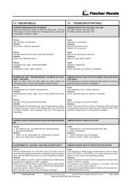
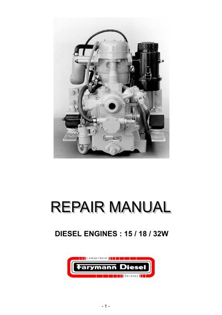
DIESEL ENGINES : 15 / 18 / 32W<br />
- 1 -
TABLE OF CONTENTS<br />
1. GENERAL INFORMATION, HANDLING 5<br />
1.3 ORGANISATION AND USE OF THIS REPAIR MANUAL.............................................................................5<br />
1.4 SERVICE.................................................................................................................................................5<br />
1.5 AFTER SALES - SERVICE: FALKE - SPARE PARTS PROGRAM ..............................................................5<br />
1.6 ENGINE, MODEL AND TYPE DESIGNATION ...........................................................................................6<br />
1.7 SAFETY INSTRUCTIONS..........................................................................................................................7<br />
2. TECHNICAL DATA 9<br />
2.1 CONSTRUCTION DATA, CONSUMPTIONS AND PRESSURES ..................................................................10<br />
2.1 CONSTRUCTION DATA, CONSUMPTIONS AND PRESSURES..................................................................11<br />
2.2 OUTPUT, TORQUE, CONSUMPTION......................................................................................................12<br />
2.2 OUTPUT, TORQUE, CONSUMPTION......................................................................................................13<br />
2.3 SCREWS - TIGHTENING TORQUES, SEALING AND ADHESIVE MATERIALS..........................................15<br />
2.4 TOOLS..................................................................................................................................................16<br />
2.5 TECHNICAL DESCRIPTION ...................................................................................................................19<br />
2.6 APPLICATIONS .....................................................................................................................................19<br />
3. DISMANTLING AND ASSEMBLY PROCEDURES ON THE BASIC ENGINE 20<br />
3.1 BASIC REQUIREMENTS ........................................................................................................................20<br />
3.2 DISMANTLING PROCEDURES ......................................................................................................21<br />
4. MEASUREMENT TABLE- WEARING PARTS 32<br />
4.1 CRANKCASE.....................................................................................................................................32<br />
4.2 CRANKSHAFT ..................................................................................................................................33<br />
4.3 CAMSHAFT .......................................................................................................................................34<br />
4.4 GEAR COVER....................................................................................................................................35<br />
4.5 SHAFTS, BEARINGS ........................................................................................................................36<br />
4.6 CONNECTING ROD..........................................................................................................................37<br />
4.7 CYLINDER LINER ............................................................................................................................38<br />
4.8 PISTON 15/18W .................................................................................................................................39<br />
4.9 PISTON 32W ......................................................................................................................................40<br />
4.10 CYLINDER HEAD 15/18W...........................................................................................................41<br />
4.11 CYLINDER HEAD 32W................................................................................................................42<br />
5. ENGINE REASSEMBLY 43<br />
6. TEST RUN, ADJUSTMENTS, CHECKS 56<br />
7. ELECTRICAL SYSTEM 66<br />
7.1 FLYWHEEL – DYNAMO / REGULATOR .................................................................................................66<br />
7.2 FUNCTION TESTS: ................................................................................................................................66<br />
7.3 HAZARDS / CAUSES OF FAILURE .........................................................................................................67<br />
7.4 12 V FLYWHEEL – DYNAMO / REGULATOR, GRAPHS........................................................................68<br />
7.5 WIRING DIAGRAMS........................................................................................................................69<br />
7.5.1 DIAGRAM 1 .................................................................................................................................69<br />
7.5.2 DIAGRAM 2 ..............................................................................................................................71<br />
7.5.3 DIAGRAM 3 ..............................................................................................................................72<br />
7.5.4 DIAGRAM 4 ..............................................................................................................................73<br />
7.5.5 DIAGRAM 5 ..............................................................................................................................74<br />
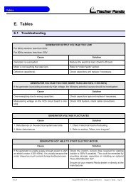
8. TROUBLESHOOTING 75<br />
8.1 ENGINE WILL NOT START.....................................................................................................................75<br />
- 2 -
TABLE OF CONTENTS<br />
8.2 ENGINE STARTS BUT FIRES INTERMITTENTLY OR DIES........................................................................76<br />
8.3 POOR ENGINE PERFORMANCE AND / OR BLACK SMOKE.......................................................................76<br />
8.4 POOR ENGINE PERFORMANCE AND/OR BLACK SMOKE ........................................................................77<br />
8.5 IMPERFECT OPERATING BEHAVIOUR ...................................................................................................77<br />
- 3 -
PREFACE<br />
We congratulate you on your choice of a FARYMANN engine and wish you much pleasure<br />
with this German quality product.<br />
These operating instructions are based on the latest state of technical development. In<br />
preparing them, every effort has been made to avoid errors. However, we accept no liability<br />
for any errors of presentation or description, nor for any omissions. Modifications may<br />
also occur because of ongoing technical developments. We reserve the right to make<br />
modifications without giving prior notice.<br />
Everyone responsible for the installation, commissioning, operation, maintenance or repair<br />
of the engines must read and follow the operating instructions and particularly the "Safety"<br />
chapter.<br />
The engine is built according to the state-of-the-art, and in compliance with recognised<br />
safety regulations. Nevertheless, while the engine is in use, there may be physical or<br />
mortal dangers to the user or to third parties, and also damage to the engine and to other<br />
property. For these reasons, the engine must only be used when it is in perfect technical<br />
condition, and when those involved are aware of the dangers and the safety precautions.<br />
In particular, malfunctions which could impair safety must be rectified immediately. The<br />
engine must only be used as intended. FARYMANN DIESEL GmbH is not responsible for<br />
damage resulting from incorrect use. Such risk is borne solely by the user.<br />
Correct use also includes following the operating instructions and adhering to the operating,<br />
servicing and maintenance conditions. The engine must only be operated and serviced<br />
by reliable, trained personnel in compliance with the relevant accident prevention<br />
regulations as well as other generally-recognised rules of safety and occupational health.<br />
FARYMANN DIESEL GmbH accepts no liability for any damage resulting from unauthorised<br />
conversions or modifications to the engine. Replacement parts must meet the technical<br />
requirements specified by FARYMANN DIESEL GmbH. This is always guaranteed if<br />
original replacement parts are used. Fitting and/or using parts and accessories not supplied<br />
by FARYMANN DIESEL GmbH may have a detrimental effect on your engine under<br />
certain circumstances.<br />
FARYMANN DIESEL GmbH accepts no liability whatsoever for any damage resulting<br />
from the use of non-original replacement parts or accessories.<br />
- 4 -
1. General Information, Handling<br />
GENERAL INFORMATION<br />
FARYMANN DIESEL engines type 15/18/32W are 4 stroke, direct injection diesel engines.<br />
They are built as single cylinder engines vertical cylinder configuration. The direct injection<br />
guarantees an outstanding level of efficiency, with low fuel consumption and excellent cold<br />
starting behaviour. Bosch fuel injection equipment is used on all engines. A high-precision<br />
centrifugal governor ensures accurate speed (RPMs) and load control.<br />
Special modified water-cooled Farymann engines fulfill BSO I/II and EPA – requirements.<br />
1.3 Organisation and Use of this Repair Manual<br />
The descriptions, data and illustrations refer to those assembly and adjustment <strong>procedures</strong><br />
where FARYMANN engines differ from ordinary diesel engines.<br />
− It is assumed that all work on the engine will be carried out by competent staff who have<br />
received training.<br />
− Special tools must be available, as described in the manual, together with good-quality<br />
standard tools.<br />
1.4 Service<br />
− If you have any further questions about the Repair Manual, we recommend you to<br />
contact your nearest FARYMANN Service Centre.<br />
− Circular letters and training courses ensure that our service personnel have an answer<br />
to every question. Please ask for a list of all our service locations from your own<br />
FARYMANN Service Centre.<br />
1.5 After Sales - Service: FALKE - Spare Parts Program<br />
"Service, Quality and Progress"<br />
is our motto. This is why we have developed our very own computer-aided "FALKE"<br />
Service System.<br />
The FALKE System makes it possible for FARYMANN’s world-wide network of distributors<br />
to satisfy all spare parts and service requirements quickly and reliably, ensuring<br />
that we maintain a close relationship with our customers.<br />
- 5 -
GENERAL INFORMATION<br />
1.6 Engine, Model and Type Designation<br />
Every engine can be unmistakably identified using the manufacturer’s nameplate. As well<br />
as the clearly defined 12-digit code number, this refers to the order number (SN) and the<br />
date of construction. This information must always be provided when making any enquiries<br />
or complaints, etc.<br />
As of July 1985, the consecutive engine number is also imprinted on the crankcase.<br />
As of July 1982, the type designation (a 12-digit code number) is used in addition to the<br />
series number (SN = Order Number). (See manufacturer’s nameplate).<br />
e.g. 18W430.0138 M5<br />
98 06 06 Date of Production<br />
- 6 -
1.7 Safety Instructions<br />
GENERAL INFORMATION<br />
Only use transport devices specified by the manufacturer, and only follow<br />
hoisting instructions specified by the manufacturer.<br />
When handling fuels, lubricants and other chemical substances, follow the<br />
safety regulations which apply to the product.<br />
Do not smoke when handling inflammable fuels or lubricants.<br />
Vapours from lubricating oil or fuel may catch fire if they come into contact<br />
with sources of ignition.<br />
Be careful when handling hot or corrosive fuels, lubricants or other substances<br />
(risk of burning or scalding).<br />
Never carry out maintenance and repair work when the engine is running.<br />
Ensure that the engine cannot start unintentionally.<br />
Before turning the engine over, make sure that nobody is in the danger<br />
area. When you have finished working on the engine, always check that<br />
the safety devices have been refitted, and that all tools have been removed<br />
from the engine.<br />
Never carry out any work on safety valves (e.g. modification of the spring<br />
tension). Defective safety valves must be replaced with new ones.<br />
When disposing of used fuels, lubricants and filters, follow the regulations<br />
which apply locally.<br />
Before or when you start the engine, check:<br />
− all lines, hoses and screwed connections for leaks;<br />
− safety devices for completeness and ability to operate.<br />
When starting the engine by hand, only use the starting device specified by<br />
the manufacturer (starting handle with kick back limiter, recoil starting) and<br />
follow the handling instructions.<br />
Never use cold starting aids based on ethyl oxide.<br />
Because of the explosion hazard, it is forbidden to start up a compressedair<br />
start engine with combustible gases (fuel gases) or oxygen, even in an<br />
emergency.<br />
- 7 -
1.5 Safety Instructions<br />
GENERAL INFORMATION<br />
Only operate IC engines in enclosed areas if there is adequate ventilation.<br />
Before you start the engine in an enclosed environment, make sure that<br />
there is sufficient ventilation.<br />
Ensure that the engine only slows down to full stop after 10 - 20 seconds!<br />
If there are any safety devices on the engine, or on the machine into which<br />
the engine is built, they must be refitted when the maintenance and repair<br />
work has been finished.<br />
Before starting any work on the electrical components, the power supply to<br />
all live parts must be cut off.<br />
Only carry out maintenance and repair work when the engine parts are in a<br />
stable position.<br />
Liquids ejected under high pressure (such as fuels or oils) may penetrate<br />
the skin and cause severe injuries.<br />
To carry out cleaning work on the engine, always use a non-combustible<br />
detergent, or one which has a flash point of more than 65 °C.<br />
CALIFORNIA<br />
Proposition 65 Warning<br />
Diesel engine exhaust and some of its<br />
constituents are known to the State of<br />
California to cause cancer, birth defects,<br />
and other reproductive harm.<br />
- 8 -
2. Technical Data<br />
TECHNICAL DATA<br />
Engine Type 15W 18W 32W<br />
Design verticall<br />
Number of Cylinders 1<br />
Bore 75 mm 82 mm 95 mm<br />
Stroke 55 mm 55 mm 74 mm<br />
Cubic capacity (piston displacement) 242 cm3 290 cm3 524 cm3<br />
Direction of rotation (looking at power takeoff<br />
side)<br />
Max. power / 3000 RPM<br />
anti clockwise<br />
F (DIN 70020) 4,76 kW 5,70 kW 9,74 kW<br />
IFN-ISO (DIN 6271) 4,33 kW 5,20 kW 8,85 kW<br />
ICFN-ISO (DIN 6271) 3,90 kW 4,70 kW 8,00 kW<br />
Max. torque 14,4 Nm 16,7 Nm 30,2 Nm<br />
(DIN 70020) at 2400 RPM at 2400 RPM at 2400 RPM<br />
Max. speed 3600 RPM<br />
Mean piston speed at 3000 RPM 5,5 m/s 5,5 m/s 7,4 m/s<br />
Compression ratio 1 : 20 1 : 19,1 – 22,6 1 : 20<br />
Valve clearance, exhaust valve 0,2 mm<br />
intake valve 0,2 mm<br />
Tank capacity --- --- ---<br />
Lubricating oil volume (sump capacity) 1,0 l 1,0 l 1,6 l<br />
Lubricating oil consumption<br />
Starter motor<br />
1,0 g/kWh<br />
rated voltage 12 V<br />
Battery capacity required 55Ah<br />
Weight 37 kg 37 kg 75 kg<br />
Cooling water requirement<br />
Permissible tilt during operation :<br />
7 – 8 l/min<br />
Longitudinal 15 °<br />
Lateral 15 °<br />
- 9 -
TECHNICAL DATA<br />
2.1 Construction Data, Consumptions and Pressures<br />
Technical Data Table 1<br />
Engine Type 15W 18W 32W<br />
Construction data dimension<br />
System * four stroke<br />
Combustion Procedure<br />
* direct injection<br />
Cooling System * Water-cooled<br />
Design / Configuration * 1-cylinder / vertical<br />
Bore (mm) 75 82 95<br />
Stroke (mm) 55 55 74<br />
Displacement (cm 3 ) 242 290 524<br />
Compression Ratio * 1 : 20,0 1 : 19.1 - 1 : 22,6 1 : 20,0<br />
Temperatures<br />
dimension<br />
Permissible air intake<br />
temperature (max.) (°C) 50<br />
Permissible exhaust<br />
gas temperature (max) (°C) 580<br />
Permissible cooling air<br />
temperature (max.) (°C) 50<br />
Permissible fuel<br />
temperature (max.) (°C) 80<br />
Permissible lub. oil<br />
temperature (max.) (°C) 130<br />
Consumptions (at IFN Output)<br />
Specific fuel consumption,<br />
3000 RPM (g/kWh) 305 300 255<br />
Fuel tank content (l) NO<br />
Feed pump (max. lift)<br />
(mm) 300<br />
Fuel * to DIN 51 601 / ASTM D 975-77 + 2D/BS 28669 1970 A1 + A2<br />
Specific lub. oil consumption<br />
(g/kWh) 1<br />
max. lub. oil capacity (g/l) 1100 / 1,25 1100 / 1,25 1380 / 1,56<br />
Topping up volume<br />
lower-upper mark (g/l) 200 / 0,226 200 / 0,226 240 / 0,270<br />
t /b tt k<br />
Lub. Oil quality * HD oil: minimum quality CC; better, CD quality (API-spec.) and multigrade oils<br />
Pressures<br />
Injector setting (bar) 200 200 175<br />
Oil pressure (max.)<br />
Permissible air intake<br />
vacuum<br />
(bar) 5<br />
(kPa) 2<br />
Permissible exhaust<br />
gas back pressure (kPa) 5<br />
- 10 -
TECHNICAL DATA<br />
2.1 Construction Data, Consumptions and Pressures<br />
Technical Data Table 2<br />
Engine Type 15W 18W 32W<br />
Adjustment Data<br />
Valves, Inlet / Outlet (mm) 0,2 all<br />
Inlet opens BTDC * 5,3°- 7,5° = 12 - 17 mm 5,3°- 7,5° = 12 - 17 mm 5,2°- 7,5° = 14 - 20 mm<br />
Exhaust closes<br />
ATDC * 4,4°- 6,7° = 10 - 15 mm 4,4°- 6,7° = 10 - 15 mm 4,5°- 6,7° = 12 - 18 mm<br />
Flywheel diameter<br />
(mm) 258 258 308<br />
Injection pump: end of delivery, plunger with control edge “above“<br />
Engine RPMs (min -1 ) 1500 1800 2000 2500 1500 1800 2000 2500 1500 1800 2000 2500<br />
End of delivery BTDC<br />
(mm) 17 18 19 17 18 19 28 28 28 32<br />
Engine RPMs (min -1 ) 2800 3000 3300 3600 2800 3000 3300 3600 3000 3300 3600<br />
2800<br />
(mm) 21 22 25 28 21 22 25 28 36 40 40 46<br />
End of delivery BTDC<br />
Injection pump: start of delivery, plunger with control edge “below“ (engines for generator and pump drive)<br />
Engine RPMs (min -1 ) 1500 1800 3000 3600 1500 1800 3000 3600 1500 1800 3000 3600<br />
Start of delivery BTDC (mm) * * 39 41 * * 39 41 42 42 60 73<br />
Valve clearance (cold)<br />
inlet and outlet valve (mm) 0,2<br />
Repair Data<br />
Dimension<br />
Inlet valve<br />
Recedes by: (mm) 0,1 - 0,2 0,1 - 0,2 0,1 – 0,2<br />
Exhaust valve<br />
Recedes by: (mm) 0,1 - 0,2 0,1 - 0,2 0,1 – 0,2<br />
Piston protrudes by: (mm) 0,63 - 0,93 0,63 - 0,93 0,65 - 0,98<br />
Gap measurement (mm) 0,47 - 0,82 0,47 – 0,82 0,43 - 0,85<br />
Piston ring joint (mm) 0,2 – 0,8 0,2 – 0,8 0,2 – 0,8<br />
Crankshaft plain bearing<br />
clearance - new condition (mm) 0,02 - 0,05 0,02 - 0,05 0,02 - 0,06<br />
Crankshaft plain bearing<br />
clearance - wear limit (mm) 0,08 0,08 0,09<br />
Connecting rod plain bearing<br />
clearance - new condition (mm) 0,03 - 0,06 0,03 - 0,06 0,03 - 0,08<br />
Connecting rod plain bearing<br />
clearance - wear limit (mm) 0,11 0,11 0,12<br />
Crankshaft end play<br />
(mm) 0,05 - 0,15 0,05 - 0,15 0,05 – 0,15<br />
- 11 -
2.2 Output, Torque, Consumption<br />
15W Leistung / Output /<br />
Puissance / Potencia<br />
Drehmoment / Torque /<br />
Couple / Par<br />
Verbrauch / Consumption /<br />
Consommation / Consumo<br />
DIN ratings<br />
TECHNICAL DATA<br />
- 12 -<br />
18W Leistung / Output /<br />
Puissance / Potencia<br />
Drehmoment / Torque /<br />
Couple / Par<br />
Verbrauch / Consumption /<br />
Consommation / Consumo<br />
F Vehicle rating: intermittent duty at variable speed and load.<br />
IFN-ISO DIN-ISO 3046 Blocked useful performance for intermittent loads.<br />
ICFN-ISO DIN-ISO 3046 Standard performance, blocked continuous useful performance for constant<br />
RPMs and constant load.<br />
D Continuous operation: - contact factory for use beyond the limits indicated.<br />
- Decrease of approx. 1% for every 100 m altitude and approx. 2% for every 5°C above<br />
20°C<br />
- Rating certified within tolerance of 5% after engine has been run in with standard air filter<br />
and exhaust muffler.
2.2 Output, Torque, Consumption<br />
TECHNICAL DATA<br />
32W Leistung / Output /<br />
Puissance / Potencia<br />
Drehmoment / Torque /<br />
Couple / Par<br />
- 13 -<br />
The values shown are<br />
related to the optimal load<br />
setting at the corresponding<br />
nominal engine speed.
TECHNICAL DATA<br />
Verbrauch / Consumption /<br />
Consommation / Consumo<br />
- 14 -
TECHNICAL DATA<br />
2.3 Screws - Tightening Torques, Sealing and Adhesive Materials<br />
Technical data Table 1<br />
Engine type 15W 18W 32W<br />
Tightening torques<br />
Cylinder head<br />
torque / wrench width<br />
Rocker bracket<br />
torque / wrench width<br />
Bearing cover<br />
torque / wrench width<br />
Connecting rod<br />
torque / wrench width<br />
Nozzle holder<br />
torque / wrench width<br />
Injection pump<br />
torque / wrench width<br />
Delivery valve<br />
torque / wrench width<br />
Flywheel<br />
torque / wrench width<br />
Speed governor<br />
torque / wrench width<br />
Maximum operation angles<br />
(Nm)<br />
(mm) 30- 33 / 13 30 - 33 / 13 52 - 56 / 17<br />
(Nm)<br />
(mm) * * *<br />
(Nm)<br />
(mm) 30 - 33 / 13 30 - 33 / 13 30 - 33 / 13<br />
(Nm)<br />
(mm) 30- 33 / 13 30- 33 / 13 52 - 56 / 17<br />
(Nm)<br />
(mm) 20 - 23 / 13 20 - 23 / 13 20 - 23 / 13<br />
(Nm)<br />
(mm) 8 – 12 / 10 8 – 12 / 10 20 - 23 / 13<br />
(Nm)<br />
(mm) 34 - 39 / 22 34 - 39 / 22 34 - 39 / 22<br />
(Nm)<br />
(mm) 8 – 12 / 10 8 – 12 / 10 390 - 410 / 46<br />
(Nm)<br />
(mm) 55 - 60 / 14 55 - 60 / 14 55 - 60 / 14<br />
Longitudinal<br />
(in dir. of crankshaft) (deg.) 15 15 15<br />
Transverse<br />
(deg.) 15 15 15<br />
Sealing and adhesive materials<br />
Text Code Type<br />
A Loctite 573<br />
B Loctite 270<br />
C Loctite 415<br />
- 15 -
2.4 Tools<br />
Part No. Description Use<br />
TECHNICAL DATA<br />
748.115.6 Fuel line clamp to clamp fuel supply<br />
lines<br />
748.130.2 Hexagonal socket<br />
wrench, 36 mm<br />
for flywheel nuts<br />
748.128.4 Drive wrench for use with socket<br />
wrench, 748.154.2<br />
748.108.5 Special screw<br />
driver<br />
748.132.6 Crankshaft race<br />
puller<br />
748.137.2 Crankshaft gear<br />
wheel puller<br />
to adjust governor<br />
spring nuts<br />
use with part no.<br />
748.136.2 to pull off<br />
main bearing race<br />
from crankshaft<br />
use with part<br />
748.136.2 to pull off<br />
crankshaft gear wheel<br />
748.136.2 Puller plate use with parts<br />
148.132.6 and<br />
748.137.2<br />
748.122.6 Flywheel puller to loosen flywheel<br />
748.119.4 Bearing driver to press in crankshaft<br />
roller bearing and shaft<br />
seal<br />
- 16 -
2.4 Tools<br />
TECHNICAL DATA<br />
748.120.4 Bearing driver to press the crankshaft<br />
bearing bushes in and<br />
out<br />
748.121.4 Bearing driver to press the camshaft<br />
in and out<br />
748.124.4 Bearing driver to press out the crankshaft<br />
roller bearing<br />
748.173.2 Oil filter wrench to remove the full flow<br />
oil filter<br />
748.172.4 Bearing driver to press the little end<br />
bearing bush in and<br />
out (connecting rod)<br />
748.129.4 Bearing driver to press the regulator<br />
shaft bearing bush in<br />
and out<br />
37E/43E:<br />
748.125.4<br />
43F:<br />
748.211.4<br />
Guide punch to press the valve<br />
guides in and out<br />
748.117.6 Drop tube to measure the injection<br />
timing<br />
- 17 -
2.4 Tools<br />
TECHNICAL DATA<br />
748.126.2 Oil pressure gauge to measure the oil<br />
pressure<br />
748.131.5 Valve spring lifter to remove and fit the<br />
valve springs<br />
- 18 -
2.5 Technical Description<br />
TECHNICAL DATA<br />
Diesel engine models 15W / 18W / 32W are water-cooled, single-cylinder, four-stroke diesel<br />
engines with direct injection. The engines have oil pressure forced lubrication. The fuel<br />
injection pump and the valves are controlled by the camshaft which is driven by the crankshaft.<br />
The fuel injection pump (self-venting fuel system) is driven directly while the valves<br />
are driven by push rods and rockers. An electric starter and a manual starting device are<br />
provided to start the engine. The engines are equipped with an automatic decompression<br />
system and a manual forced starting enrichment quantity.<br />
Special modified water-cooled Farymann engines fulfill BSO I/II and EPA – requirements.<br />
2.6 Applications<br />
Diesel engine models 15W / 18W / 32W are suitable for the following applications:<br />
− Marine generating sets<br />
− Marine propulsion engines<br />
− Vehicle cooling systems<br />
− Military Equip. ( APU, ... )<br />
−<br />
− .<br />
- 19 -
RE-ASSEMBLING PROCEDURES<br />
3. Dismantling and Assembly Procedures on the Basic Engine<br />
3.1 Basic Requirements<br />
ATTENTION<br />
CAUTION<br />
� Advice<br />
− The aim of this Repair Manual is to provide<br />
help with carrying out repairs to the<br />
engine.<br />
The requirements for this are as follows:<br />
− Trained specialist staff (of at least the<br />
minimum legal age);<br />
− and a workshop where the necessary<br />
equipment, standard tools and special<br />
tools are available<br />
− A well-lit, unrestricted working area, free<br />
from dirt and swarf, will make the work<br />
considerably easier.<br />
− Clean the engine thoroughly before dismantling<br />
it.<br />
− Attention must be paid to all the information<br />
and warning notices which have been<br />
affixed.<br />
− Particular care is called for in the vicinity of<br />
rotating, moving or hot parts.<br />
This symbol is used whenever failure to<br />
comply precisely with instructions or <strong>procedures</strong><br />
may cause accidents which can result<br />
in injuries or death.<br />
This symbol is used whenever failure to<br />
comply precisely with instructions or <strong>procedures</strong><br />
may cause damage to the engine.<br />
and tips about special features when<br />
handling the engine.<br />
- 20 -
RE-ASSEMBLING PROCEDURES<br />
3.2 DISMANTLING PROCEDURES<br />
1. Drain lubrication oil :<br />
Place suitable container under the drain hole.<br />
Remove 2 screws and cupper washers, remove<br />
oilscreen.<br />
Caution<br />
Clean oilscreen carefully.<br />
Replace if any deformations or other damages.<br />
2. Air cleaner<br />
Engines installed in Generating Sets<br />
Aircleaner-assy done from equipment manufactorer.<br />
Follow instructions of the operating manual.<br />
Marine propulsion engines<br />
There are different versions of aircleaner and<br />
noise damper in use. In each case remove the<br />
2 selflocking nuts and pull of the assy.<br />
Discard gasket and replace filter element if existing.<br />
3. Muffler / Exhaust manifold<br />
Engines installed in Generating Sets<br />
Muffler-assy done from equipment manufactorer.<br />
Follow instructions of the operating manual.<br />
Marine propulsion engines<br />
Special watercooled exhaust manifold.<br />
Remove 2 hex-nuts and washers.<br />
Discard gasket.<br />
Replace clamp of the water-line if necessary.<br />
- 21 -
RE-ASSEMBLING PROCEDURES<br />
- 22 -<br />
4. Fuel lines, fuel filter<br />
Remove banjo bolts, copper washers from injection<br />
pump and injector. If existing – remove fuel<br />
filter bracket, setscrews and spring washers.<br />
Close ports of injection pump and injector with<br />
banjo bolts to prevent dirt.<br />
Caution<br />
Use only original fuel filter and fuel persistened<br />
fuel lines for replacement.<br />
Example : Fuel system Genset engine Example : Fuel system Propulsion engine
5. High pressure fuel line :<br />
Loosen the high pressure fuel line by holding a<br />
14 mm wrench on the delivery valve while unscrewing<br />
the fuel line fitting.<br />
Loosen the high pressure line at the injector in<br />
the same way.<br />
Caution<br />
Check taper ends of the high pressure line for<br />
damage or wear.<br />
Replace if necessary.<br />
6. Fuel injector :<br />
RE-ASSEMBLING PROCEDURES<br />
Remove hex nuts and lock washer from injector<br />
clamp. Pull out injector.<br />
Caution<br />
Sticking injector : Use a soft faced hammer and<br />
tap slightly.<br />
OR : Take an old high pressure line to pull the<br />
injector out.<br />
Check injector and cylinder head bore for the<br />
copper washer ! Copper washer has to be repplaced<br />
in all cases !<br />
- 23 -
RE-ASSEMBLING PROCEDURES<br />
- 24 -<br />
7. Cylinder head :<br />
Remove the valve cover by removing the lock<br />
nuts and the plastic washers. If necessary tap<br />
the cover lightly with a soft faced hammer. Discard<br />
plastic washers and valve cover gasket.<br />
Remove the 2 locknuts and washers (1) holding<br />
the protection tube retaining spring.<br />
Loosen the 4 cylinder head nuts (2) using a<br />
torque wrench.<br />
Drive out the rocker arm bolt with a drift pin and<br />
a hammer.<br />
Remove rocker arms and push rods.<br />
Check rocker arm bushings for wear.<br />
Replace bushings if necessary.<br />
Check push rods for bending and wear at the<br />
taper ends<br />
Replace if necessary..<br />
Remove the cylinder head nuts and cylinder<br />
head. Remove the protection tube.<br />
Remove cylinder head gasket using a screwdriver.<br />
Check valves, valve seat and valve guide for<br />
wear or damage. Replace if necessary.<br />
Check blanking plugs ( water cooling room ) for<br />
leakage.<br />
Caution<br />
Use a valve spring compressor to remove the<br />
valves.<br />
Valve guides can be easy removed with a valve<br />
guide driver ( refer to Special Tool List ! )
8. Decompression release<br />
Remove 2 screws and pull the decompression<br />
Release out of the gearhousing.<br />
RE-ASSEMBLING PROCEDURES<br />
Check gasket and o-seal. Replace if necessary.<br />
Caution<br />
Take care not to loose the guide pin !<br />
With missing guide pin shaft will move out when<br />
engine is in operation !<br />
9. Cylinder<br />
Rotate the flywheel until the piston the bottom of<br />
ist stroke. Carefully slide the cylinder up of the<br />
studs.<br />
Check o-seals of water-overflow-jackets. Replace<br />
if necessary.<br />
Caution<br />
If the repair doesn’t require replacement of piston<br />
and liner, leave the liner on the piston.<br />
Pull up liner so far that piston pin bore is free -><br />
See next step.<br />
- 25 -
10. Piston<br />
RE-ASSEMBLING PROCEDURES<br />
Rotate the flywheel until the piston is in TDC –<br />
position. Use a needle nose plier to remove the<br />
piston pin retainer.<br />
With a drift pin gently hammer piston pin out of<br />
the piston ( from flywheel-side ).<br />
Caution<br />
If the piston pin is sticking you’ve to remove the<br />
complete piston and conrod assy. Remove piston<br />
pin on the work bench.<br />
11. Conrod<br />
Turn the flywheel untol piston is in BTC–position.<br />
Put the engine down on flywheel-side. Remove<br />
the crankcase bottom plate by unscrewing<br />
the 6 head screws.<br />
Discard gasket.<br />
Caution<br />
If the screws are very tight tap them with a<br />
hammer and and drift pin.<br />
When reusing the conrod bearings you have to<br />
mark the bearing shells and the corresponding<br />
parts of the conrod. This ensures that the bearing<br />
runs in the same postion again after installation.<br />
Use a 13 mm socket to remove the hex nuts.<br />
Pull out the conrod big end using a plier.<br />
- 26 -
RE-ASSEMBLING PROCEDURES<br />
- 27 -<br />
12. Crankhandle guide<br />
Remove the 2 crankhandle guide screws. Pull of<br />
the guide in a twisting motion.<br />
13. Gear end cover<br />
Remove the 6 allen screws and pull off the gear<br />
end cover.If necessary tap with a soft faced<br />
hammer.<br />
Caution<br />
While removing the gear end cover the gear of<br />
the camshaft could stick on the governor-body.<br />
¼ turn of the flywheel will free it !<br />
14. Injection pump<br />
Move accelleration lever to full speed position.
To remove the injection pump camfollower unscrew<br />
fixing screw ( arrow )through oil filling<br />
bore.<br />
RE-ASSEMBLING PROCEDURES<br />
15. Camshaft<br />
Remove the circlip lock ring fixing the camshaft<br />
in the gear end cover. Press out the camshaft<br />
using a driver ( see special tool list ).<br />
To pull off the camshaft gear wheel use puller or<br />
press.<br />
After removing the camshaft the roller bearing<br />
can be pressed out from the inside of the cover<br />
using a special driver.<br />
- 28 -<br />
Remove the 2 hex nuts and lock washers. Pull<br />
off the inj. Pump. If necessary turn the flywheel<br />
to decrease force from the camshaft-side.<br />
Caution<br />
Leave gasket and shimson the gear end housing.<br />
Re-install hex nuts and lock washers on<br />
their studs.
RE-ASSEMBLING PROCEDURES<br />
16. Speed control assembly<br />
Remove the retaining ring from the eccenter<br />
shaft using a pliers. Pull the exc. shaft outwards<br />
till the ratchet plate is free from the compression<br />
pin. Unhook the outer torsion spring from the<br />
boss ( use a pliers and watch out for your fingers).<br />
Hold the inner control lever and twist acceleration<br />
lever down to stop-position till the<br />
inner torsion spring is without tension. Then pull<br />
eccenter shaft out of control lever and bearing<br />
bush.<br />
- 29 -<br />
17. Governor<br />
Install holding device ( special tools )<br />
Remove governor pin from governor.<br />
Spread flywheights with a screwdriver and use<br />
14 mm socket to unscrew governor.<br />
Caution<br />
Governor mounted with left-hand-thread !
20. Main bearing housing<br />
Remove the 4 main bearing housing nuts and<br />
washers.<br />
Next install 2 screws M6 x 30 into the thread<br />
holes. Screw them in until the housing breaks<br />
loose.<br />
RE-ASSEMBLING PROCEDURES<br />
- 30 -<br />
18. Oil pump<br />
Remove the oil pump and valve bracket by unscrewing<br />
the 3 mounting screws.<br />
Discard gasket.<br />
19. Flywheel<br />
Remove the oil pump and valve bracket by unscrewing<br />
the 3 mounting screws.<br />
Discard gasket.<br />
Leave the flywheel nut on the shaft. Install flywheel<br />
puller and turn the screws until the flywheel<br />
breaks loose from the crankshaft tapper.<br />
Remove the puller, flywheel nut and flywheel.
RE-ASSEMBLING PROCEDURES<br />
Remove the key, belleville washers, angle ringe,<br />
o-ring and thrust washer.<br />
21. Crankshaft<br />
Remove the crankshaft from the crankcase, being<br />
careful not to drag the crankshaft gear on the<br />
main bearing bushing.<br />
Use a puller to pull of the crankshaft gear.<br />
In case the roller bearing needs replacement,<br />
replace also the inner race, which is shrunk fit<br />
on to the crankshaft.<br />
Use race puller to pull off the inner race.<br />
The engine is now completely stripped down.<br />
Clean all parts with diesel fuel or other suitable<br />
cleaning agent.<br />
Check parts for damaga, wear and tear.<br />
Replace is necessary.<br />
- 31 -
MEASUREMENT TABLE, WEAR<br />
4. MEASUREMENT TABLE- WEARING PARTS<br />
4.1 CRANKCASE<br />
- 32 -
4.2 CRANKSHAFT<br />
MEASUREMENT TABLE, WEAR<br />
- 33 -
4.3 CAMSHAFT<br />
MEASUREMENT TABLE, WEAR<br />
- 34 -
4.4 GEAR COVER<br />
MEASUREMENT TABLE, WEAR<br />
- 35 -
4.5 SHAFTS, BEARINGS<br />
MEASUREMENT TABLE, WEAR<br />
- 36 -
4.6 CONNECTING ROD<br />
MEASUREMENT TABLE, WEAR<br />
- 37 -
4.7 CYLINDER LINER<br />
MEASUREMENT TABLE, WEAR<br />
Dimensions :<br />
15W 18W 32W<br />
A 92 –0,05 92 –0,05 109,2 –0,1<br />
B 75,050 – 75,030 82,050 – 82,030 95,040 – 95,020<br />
C 78,8 –0,1 85,0 –0,2 100,5 –0,2<br />
D 95 –0,036 /-0,071 95 –0,036 /-0,071 117 –0,1 / -0,15<br />
E 86,75 –0,025 86,75 –0,025 111,2 –0,025<br />
F 105,75 –0,1 105,75 –0,1 138,2<br />
- 38 -
4.8 PISTON 15/18W<br />
MEASUREMENT TABLE, WEAR<br />
- 39 -
4.9 PISTON 32W<br />
MEASUREMENT TABLE, WEAR<br />
- 40 -
4.10 CYLINDER HEAD 15/18W<br />
Cylinder head 15W<br />
Cylinder head 18W<br />
MEASUREMENT TABLE, WEAR<br />
- 41 -
4.11 CYLINDER HEAD 32W<br />
Cylinder head 32W<br />
Rocker arm 15/18/32W<br />
MEASUREMENT TABLE, WEAR<br />
- 42 -
5. ENGINE REASSEMBLY<br />
1. Crankcase<br />
Press the bearing bush with a suitable driver.<br />
Caution<br />
Take care that the joining line of the bearing<br />
bush is located as shown and that the oil holes<br />
in the bushing and in the crankcase bore are<br />
properly linedup.<br />
2. Crankshaft<br />
To install the crankshaft gear and the inner race<br />
of the roller bearing heat up the parts to a temp.<br />
Of 90°C - 100°C ( 195 – 210 °F ).<br />
-> use oil bath or electric heater plate.<br />
Oil the bearing bush and slide crankshaft into<br />
the crankcase. Take care not to damage the<br />
bearing bush with the gear teeth.<br />
REASSEMBLY PROCEDURES<br />
- 43 -
REASSEMBLY PROCEDURES<br />
- 44 -<br />
3. Main bearing housing<br />
Press the outer race of the driver into the bearing<br />
cover. Insert the retaining ring with pliers.<br />
Press the oil sealing ring into the housing using<br />
the correct driver. Don’t use grease for assembly.<br />
Insert o-ring in the bearing housing and put<br />
onto studs.<br />
Caution<br />
Bearing housing can only be fitted in one position.<br />
Tap lightly with a soft faced hammer to seat<br />
the cover. Torque down the fastening nuts<br />
crosswise.<br />
Assemble the thrust washer (1) and o-ring (2),<br />
followed by the angle ring (3) and the two<br />
belleville washers (4) exactly as shown.<br />
4. Flywheel<br />
Clean crankshaft and flywheel tapper free of oil<br />
or grease. Insert flywheel key and slide flywheel<br />
onto the crankshaft tapper. Assemble flywheel<br />
retaining nut and tighten to specified torque.
5. Oilpump<br />
Reassemble oilpump with thin pressure relief<br />
plate, spring retaining clip and gasket. Before<br />
tightening the screws to specified torque pull the<br />
pump downwards. The clearance in the screw<br />
holes allows a sufficient backslash between<br />
crankshaft gear and pump gear.<br />
6. Governor<br />
Install holding device ( special tools ) on crankshaft<br />
or fix crankshaft with a hammer stick.<br />
Make sure that governor and crankshaft threads<br />
are free of oil and grease. Apply a couple of<br />
trops of Loctite 270 ( or similar ) on the governor<br />
thread. Torque the governor down according the<br />
torque table.<br />
Attention<br />
Governor with lefthand thread ! Spread flywheights<br />
to mount the socket of the torque<br />
wrench.<br />
For correct governor setting refer to section Adjustments<br />
!<br />
7. Connecting rod<br />
To install new bearing shells, take a shell half<br />
and lay it to approx. ¾ into the cap. Now press<br />
the bearing in a slidung move onto its seat. The<br />
bearing lip must fit into the groove in the cap.<br />
Install the bearing shell on the rod-side in the<br />
same way.<br />
REASSEMBLY PROCEDURES<br />
- 45 -
REASSEMBLY PROCEDURES<br />
- 46 -<br />
Notice the stamped numbers on conrod and cap<br />
– side . These are matcjing marks i.e. identical<br />
numbers must be on rod and cap.<br />
Oil the bearing shells and install conrod into the<br />
crankcase until it seats on the crank pin. Insert<br />
conrod cap through the bottom inspection cover<br />
Attention<br />
The stamped numbers must be aligned on the<br />
same side of the rod but it is not important which<br />
engine side the numbers face. Thighten the conrod<br />
nuts to the specified torque and reinstall<br />
crankcase cover.<br />
.<br />
8. Camshaft<br />
Heat the camshaft gear wheel in an oil bath or<br />
an electric heater plate to 90-100 °C ( 195-210<br />
°F). Thrust gear onto the camshaft using a suitable<br />
lenght of pipe and a hydraulic press.<br />
Attention<br />
The timing mark must face towards cam side of<br />
assembly.<br />
Press the camshaft bearing into the gear<br />
end cover using a driver.
Now press the camshaft with a driver into<br />
the bearing. Use another driver as counter<br />
pressure piece for the bearing. Make sure<br />
that the bearing sears fully against the seat<br />
flange. Insert retaining ring. Install camfollower<br />
for the injection pump and tighten the<br />
fixing screw.<br />
Every time install a new o-ring on the camshaft<br />
prior to pressing the camshaft into the<br />
bearing.<br />
9. Governor control<br />
Insert ratched pin and spring into the hole in the<br />
gear end housing.<br />
Put the return spring (1) into small hole of the<br />
control lever.<br />
Move the torsion spring (2) over the eccentric<br />
shaft and hook spring leg in the space in the<br />
middle of the ratched plate (3).<br />
Slide the eccentric shaft through the bearing<br />
bush in the housing and into the control lever.<br />
Turn the acceleration lever downwards (“stop”)<br />
until spring leg of the return spring can be<br />
moved into the notch of the eccentric shaft end.<br />
(Figure c).<br />
REASSEMBLY PROCEDURES<br />
c<br />
Push in eccentric shaft and clip ring spring into<br />
- 47 -<br />
Use a wire loop to move and hook torsion spring<br />
leg to the boss of the gear end housing.<br />
(Figure d)<br />
d
the notch of the eccentric shaft.<br />
Attention<br />
Initiate performance test.<br />
The tension of the return spring must be acting<br />
against the pressure onto the seting screw.<br />
Speed control - Stationary<br />
The outer torsion spring pulls the acceleration<br />
lever from the stop-position back into idleposition.<br />
Speed control – Vehicle / Bowden cable<br />
The outer torsion spring pulls the acceleration<br />
lever into stop-position.<br />
Speed control – Generator<br />
The outer torsion spring pulls the acceleration<br />
lever into full-speed-position.<br />
Attention<br />
The spring tension may be altered by hooking<br />
the spring leg into one of the neighboured<br />
notches !<br />
10. Piston<br />
Install the piston rings using a ring expander.<br />
Imprinted sign has to be on top.<br />
REASSEMBLY PROCEDURES<br />
- 48 -
Note : Picture shows air cooled cylinder head !<br />
REASSEMBLY PROCEDURES<br />
- 49 -<br />
Oil the ring and piston skirts. Check that piston<br />
ring gaps are 120 degrees offset. Compress<br />
rings with ring compressor. Lay the cylinder<br />
down on the bench with bottom facing up. Install<br />
piston from bottom side of the cylinder. Never<br />
tap on the piston crown.<br />
Attention<br />
Never try to install piston through top of the liner<br />
as liner is slightly tapered. Push in the piston so<br />
far that the piston pin bore is slightly above edge<br />
of cylinder.<br />
Slide the piston and cylinder over the studs.<br />
For 18W / 32W only :<br />
The arrow-sign ( or crankshaft-sign ) stamped<br />
on the piston top must point towards the flywheel.<br />
Align the piston and conecting rod bores. Push<br />
the piston pin in and insert the retaining<br />
ring.Push the cylinder down until it seats firmly<br />
onto the engine crankcase.<br />
11. Cylinder head<br />
Press the valve guides into the cylinder head<br />
using a driver. Special care is necessary to ensure<br />
that the guide is exactly vertical before<br />
pressing in.<br />
Attention<br />
Before pressing in the exhaust valve guide, assemble<br />
the two small washers and retainer ring.
Grind in the valves. The rotocap and the conical<br />
shaped spring belong to the exhaust valve. The<br />
two thin steel washers must be under the cylindrical<br />
spring of the inlet valve. Fit new sealing<br />
cap onto the inlet valve guide. Before fitting the<br />
rotocap check for proper function : Spin the cap,<br />
if rattling sound or hard movement -> replace.<br />
NOTE :<br />
32W engine => There’s no difference between<br />
inlet and exhaust valve spring !<br />
Fit cylinder head gasket and slide cylinder head<br />
down onto the cylinder. Fit spring washers and<br />
cylinder head nuts. On the shorter stud – intake<br />
side –fit the tote bracket and cylinder haed nut<br />
without washer.<br />
Attention<br />
Model 15W doesn’t have any cylinder head gasket.<br />
At this stage don’t torque down the cylinder<br />
head nuts as the rocker arms and push rods still<br />
have to be assembled at a later stage !<br />
Recommented torque at this stage : 5 Nm<br />
REASSEMBLY PROCEDURES<br />
- 50 -
REASSEMBLY PROCEDURES<br />
- 51 -<br />
12. Gear end cover<br />
To install the gear end cover, first bring the piston<br />
to TDC ( Top dead center ) position by<br />
aligning the flywheel timing mark with the TDC<br />
mark stamped on the crankcase.<br />
Insert the governor pin into the bore in the governor.<br />
Use grease to keep the pin in place.<br />
Line up the timing mark on the camshaft gear<br />
with the mark on the gear end cover.<br />
Install the gear end cover onto the crankcase<br />
being careful not to move the camshaft gear.<br />
Remember to place the gasket !<br />
After the cover is installed check the timing<br />
marks on the flywheel side. If both marks are<br />
within +/- 2mm lining up the timing is correct.<br />
Insert the governor pin into the bore in the governor.<br />
Use grease to keep the pin in place.<br />
Occasionally, however, the governor will tighten<br />
onto the crankshaft in position that makes it difficult<br />
to install the gear end cover. If this happens<br />
use the following procedure to install the<br />
cover :<br />
Turn the flywheel until ist timing mark aligns with<br />
approx. 1 o’clock position.
Move the timing mark on the camshaft gearexactly<br />
3 teeth to the left.<br />
Install the gear end cover. Align the flywheel<br />
mark and the crankcase timing mark.<br />
Check timing marks on camshaft gear and gear<br />
end cover. The timing is acceptable if these are<br />
within 0 – 2 mm to the left side !<br />
Note :<br />
If the camshaft mark is in right side position the<br />
valves will come in contact with the piston ( hot<br />
engine ).<br />
Place new o-ring in the flute of the crankhandle<br />
support. Lubricate the camshaft and the sealing<br />
lips of the oil sealing ring. Don’t push the guide<br />
straight onto the gear end cover. Instead use a<br />
light twisting motion until the guide seats itself.<br />
Tighten the screws to specified torque.<br />
13. Decompression device<br />
Slide the pushrod tube up into the ist hole in the<br />
cylinder head as far as possible. Remember to<br />
install a new o-ring in the cylinder head. To<br />
grease will help to assemble the tube.<br />
Assemble the decompression device with new<br />
o-ring and gasket.<br />
Attention<br />
Before reinstalling the decompression device<br />
check if the retaining pin for the shaft is still in<br />
place ( see arrow ).<br />
REASSEMBLY PROCEDURES<br />
- 52 -
REASSEMBLY PROCEDURES<br />
- 53 -<br />
When a new decompression device is installed<br />
the correct function must be checked. To do so<br />
install the decompression device with the 0,4<br />
mm thick gasket. Continue with steps 14, 15 and<br />
16. Turn the flywheel approx. 1/8 revolution before<br />
TDC and measure with a depth gauge the<br />
distance between bracket of the rocker arm<br />
shaft and spring collar of the intake valve. Next<br />
activate the decompresion device and measure<br />
the distance again. There must be a difference<br />
between the two measurements of about 0,7 –<br />
0,9 mm. If it is less than 0,7 mm you’ve to disassemble<br />
the deco device and replace the 0,4 mm<br />
gasket with two 0,3 mm gaskets ( all included in<br />
the joint set ). Carry out the two measurements<br />
again.<br />
If the tolerance is more than 1,0 mm replace the<br />
0,4 mm gasket with a 0,3 mm gasket. Carry out<br />
the two measurements.<br />
14. Push rods and protection tube<br />
Slide the protection tube down onto the decompression<br />
device. Assemble the retaining spring<br />
exactly as shown.<br />
Don’t tighten the nut yet.<br />
Insert the push rods through the protection tube<br />
into top of the decompression device. Both push<br />
rods are alike. Intake push rod has to be placed<br />
into tapped top hole closest to cylinder.<br />
15. Rocker arms<br />
Place piston to TDC position. Line up rocker<br />
arms and push rods.<br />
Oil rocker arm bolt before installing it into the<br />
support.<br />
Attention<br />
To prevent damage of push rods while torquing<br />
the cylinder head nuts, ensure sufficient clearance<br />
between setting screws and push rods.<br />
Tighten cylinder head nuts in 3 steps to specified<br />
torque.
16. Valve setting<br />
Check that the decompression device is in operating<br />
position ( pin on 9 o’clock ). Set piston on<br />
TDC compression stroke. Use a 0,2 mm feeler<br />
gauge to control and reset the valve clearance<br />
of both valves. ( Insert feeler gauge between<br />
valve stem and rocker arm ). Open the lock nuts<br />
of the setting screws to reset clearance. Tighten<br />
the nuts while counterhold the setting screws<br />
with a screwdriver. Recheck clearance when<br />
finished.<br />
Attention<br />
Valve setting on installed engines :<br />
Remove valve cover. Insert a crankhandle and<br />
rotate slowly to valve overlaping position.<br />
Remove crankhandle and check drive pin inside<br />
the crankhandle guide => vertical position !<br />
Insert crankhandle once again ad turn around ½<br />
rotation ( drive pin = vertical position again ! )<br />
Check and reset the valves.<br />
17. Oil filter => 32W engine, only<br />
Fill up oilfilter with new oil.<br />
Oil the rubber gasket and screw on oilfilter.<br />
Attention<br />
Hand tighten oilfilter only. Don’t use tools.<br />
Install oil drain flange ( oil screen assy ). Fill trhe<br />
engine with new oil up to dipstick mark between<br />
upper and lower position. Recheck oil level after<br />
first engine start.<br />
18. Fuel injector<br />
Replace the old cupper washer located in the<br />
cylinder head injector seat.<br />
Attention<br />
Use one washer only !<br />
Make sure that the old one has been removed.<br />
Install injector and clamp. Torque the two nuts<br />
as specified.<br />
REASSEMBLY PROCEDURES<br />
- 54 -<br />
NOTE :<br />
Use only OEM oilfilter !<br />
The recommended filter is special made to be<br />
high resistant against vibration shocks !<br />
A special relief valve inside the oilfilter protects<br />
your engine against total damage !<br />
NOTE :<br />
On used injectors you’ve to ckeck the injector<br />
pressure and orifices !<br />
If nessecary reset pressure setting as specified<br />
in the technical tablets !
REASSEMBLY PROCEDURES<br />
- 55 -<br />
19. Injection pump<br />
Place acceleration lever in full load (max speed)<br />
position and pull excess fuel button. Place rod of<br />
the fuel injection pump to max position. When<br />
sliding in the pump, the pin of the rod must grip<br />
into the yoke of the control lever. Reinstall the<br />
injection pump by using the same number and<br />
types of shims as were on the engine before.<br />
(See chapter -> injection timing !)<br />
First install the paper gasket in any case.<br />
Attention<br />
To check correct assembly of the fuel injection<br />
pump turn the acceleration lever to stopposition.<br />
Excess fuel button must push back to<br />
normal operating position !<br />
20 High pressure fuel line<br />
Install the high pressure fuel line and tighten the<br />
union nuts on injector and pump. While tightening<br />
nut on injector and pump maintain counter<br />
parts with a 14 mm wrench.<br />
21 Valve cover<br />
Install the valve cover gasket and the valve<br />
cover taking care the gasket is properly seated<br />
on the cylinder head. Insert new plastic washers<br />
and tighten to specified torque.
6. Test run, adjustments, checks<br />
1. TEST RUN<br />
The engine is now completely reassembled.<br />
Install engine on test bench and carry out test<br />
run. The engine does not require a long time<br />
running-in program. After a ahort run according<br />
to low specifications the engine is ready for<br />
normal operation.<br />
Also the use of special break-in oils or lub. Oil<br />
additives are not recommended.<br />
Note<br />
Running-in instruction :<br />
=> 5 min idle speed, no load<br />
=> 10 min half speed, half load<br />
=> 20 min full speed, nominal load => output setting<br />
!<br />
=> 2 min idle speed for cooling down<br />
During test run check for proper function, unusual<br />
noise and leakages.<br />
2. Lubrication system, basic info<br />
32W – engines:<br />
A gear pump sucks the oil from the sump and<br />
conveys the oil through the oilfilter to the main<br />
bearing and conrod bearing. Piston, piston pin,<br />
cylinder liner and rocker arms are splash lubricated.<br />
Max.oil pressure ( 4,5 bar ) is controlled<br />
by a relief valve ( mounting support of the oilfilter<br />
).<br />
15 / 18W – engines, differences:<br />
Oil strainer instead of oil filter. Oil pump with<br />
integrated pressure relief system.<br />
Note<br />
All engines require heavy duty lub oils of at least<br />
CC, preferably CD quality. ( API classification ).<br />
For correct viscosity and oil change intervalls<br />
refer to Operating Manual !<br />
TEST RUN, ADJUSTMENTS<br />
- 56 -
3. Oil pressure check<br />
The oil pressure depends mostly on the wearing<br />
conditions of the bearings. Before checking the<br />
oil pressure make sure that the oil level is<br />
topped and oil with correct viscosity is used.<br />
Remove the oil channel plug screw and connect<br />
oil pressure gauge with adaptor.<br />
Oil pressure values, hot engine ):<br />
Idle speed => min press. 0,5 bar ( 7 PSI )<br />
Nominal speed => min press. 1,8 bar ( 23 PSI )<br />
If oil pressure is to low first check the pressure<br />
relief valve before starting further dismantling of<br />
the engine.<br />
4. Fuel system, basic<br />
The fuel flows from the (ext.) tank through the<br />
fuel feed pump ( option ), fuel filter to the injection<br />
pump. Higher supplied quantity will flow<br />
back via return line. Returning fuel carries heat<br />
away from the system.<br />
Returning fuel also ensures a constant bleed in<br />
the fuel system.<br />
From the injection pump fuel is fed through the<br />
high pressure line to the injector. Higher supply<br />
will be carried back through the return line.<br />
Injector pressure settings:<br />
15/18W – engines : 200 bar<br />
32W – engines : 175 bar<br />
5. Fuel filter<br />
The fuel filter prevents the entry of dirt into the<br />
injection pump. The normal lifespan of a fuel<br />
filter is approx. 1000 operating hours, however it<br />
depends on the purity of the fuel used.<br />
Prior to changing fuel filter, clean the fuel lines<br />
from dirt with a rag. Close off the line between<br />
filter and tank with a clamp.<br />
TEST RUN, ADJUSTMENTS<br />
- 57 -<br />
15/18W – engines :<br />
Plug screw located on crankcase side.<br />
Pull the inlet and outlet line from the filter. Discard<br />
the used filter ! Don’t try to clean it !<br />
Reassemble and check correct connection.<br />
Note<br />
Watch out for the correct direction of flow (<br />
signed on filter Housing ).
6. Fuel injector, injector nozzle<br />
The injector nozzle injects the fuel in a fine mist<br />
and under a high pressure into the combustion<br />
space. Due to the high mechanical and thermal<br />
stress, the nozzle requires regular maintenance.<br />
Carbon resuides on the nozzle tip are removed<br />
with a brass wire brush.<br />
The spray holes can be cleaned with a special<br />
needle ( Bosch tool ).<br />
To check the injection pressure, connect the<br />
complete injector to a nozzle tester. Follow operating<br />
instructions. The fuel must be ejected<br />
evently atomized without drippling at the specified<br />
pressure.<br />
Caution<br />
Keep hands away from nozzle spray ! The spray<br />
can penetrate deep into the flesh of your hand<br />
and destroy the tissues. Diesel fuel can cause<br />
blood poisoning.<br />
If injection pressure is too high or low, it must be<br />
corrected by replacing the shims inside the injector<br />
valve.<br />
Procedure :<br />
Unscrew the sleeve nut (1), take of the nozzle<br />
(2), pressure piece (3), valve cone (4) and pressure<br />
spring (5). Replace adjustment shims !<br />
Thicker shim => higher pressure<br />
Thinner shim => lower pressure<br />
An alteration of 0.1 mm ( 0.004”) will bring a<br />
change of approx. 10 bar ( 145 PSI).<br />
When reassembling take care that the pins on<br />
the pressure piece are correctly located in nozzle<br />
body and nozzle holder. If the nozzle leaks,<br />
dribbs or does not atomize properly, change the<br />
complete nozzle.<br />
All kinds of repair are not recommended.<br />
TEST RUN, ADJUSTMENTS<br />
- 58 -
7. Excess starting fuel button<br />
For ease of starting all engines are fitted with an<br />
excess starting pull button.<br />
A cone limits the travel of the fuel rack. When<br />
the starting fuel button is pulled down prior to<br />
start, the cone allows the fuel rack to travel to a<br />
higher fuel quantity position.<br />
As soon as the engine reaches ist high idle<br />
speed the governor moves the fuel rack towards<br />
stop, the starting fuel button disengages and<br />
returns to ist normal operating position.<br />
Therefore it is necessary to start the engine<br />
without load in order to reach max rpm. Otherwise<br />
the starting fuel button will not diengage<br />
and continously overload the engine.<br />
Also the engine output is adjusted via the cone<br />
of the starting fuel button. Depending in the installation<br />
depth of the cone the fuel rack travel is<br />
shorter ( = less output ) or longer ( = higher output<br />
). This output adjustment is done on the<br />
factory’s test-bench. Under no circumstance–<br />
this setting should be altered.<br />
If the excess fuel button or the complete gear<br />
cover was renewed, the engine output must be<br />
re-adjusted on a test bench.<br />
TEST RUN, ADJUSTMENTS<br />
- 59 -
8. Adjustment of fuel injection timing<br />
The correct setting of the commencement of<br />
delivery is a basic requirement for a troublefree<br />
function of the engine. As the injection timing is<br />
fixed, a check and re-adjustment is only necessary<br />
when the engine speed is altered or the–<br />
camshaft gear was renewed.<br />
Note<br />
Engines for generating sets are set at “ begin of<br />
delivery “ point. Propulsion engines are set at<br />
end of delivery “ point !<br />
First crank the engine to compression stroke till<br />
TDC mark on the flywheel is approx. at 5 o’clock<br />
position. Close fuel supply line.Remove the allen<br />
head screw from injection pump head and the<br />
cupper washer inside. Fit drip tube (=> tools).<br />
Set the acceleration lever at max speed.<br />
Attention<br />
Excess starting fuel button must not be pulled !<br />
Open fuel supply line. Slowly crank the engine<br />
rotationwise and observe the drip tube. First the<br />
fuel flows free => drips => stops => drips and<br />
flows again.<br />
Last drips before stop : begin of delivery point !<br />
First drips after stop : end of delivery point !<br />
The delivery cut-off point is correct when approx.<br />
1 drop per second comes out of the tube.<br />
Use a flexible ruler and measure the distance<br />
between TDC marks on the flxwheel and crankcase.<br />
Compare the measured data with the values<br />
recommended at the Technical Data Table.<br />
Observe correct flywheel diameter and engine<br />
speed !<br />
If the measured value is out of tolerance, readjust<br />
the commencement of delivery, either by<br />
adding or removing adjustment shims.<br />
Adding shims : delayed injection => shorter distance<br />
between TDC marks !<br />
Removing shims : advanced injection => longer<br />
distance between TDC marks !<br />
TEST RUN, ADJUSTMENTS<br />
- 60 -
If shims have been added or removed the installation<br />
deepth muist be checked.<br />
Measure distance from the mounting flange<br />
down to the edge inside the roller tapped. This<br />
value plus the thickness of the installed adjustment<br />
shims should be between 57,5 mm<br />
(2.263”) and 59,1 mm (2,327”) !<br />
If it is not possible to set the correct injection<br />
timing via adjustment shims, then most probably<br />
the alignment of the camshaft gear is not correct.<br />
Or TDC marks is wrong.<br />
Attention<br />
The thickness of the adjustment shims is<br />
stamped on the mounting flange of the injection<br />
pump. Example : “12” => 1,2 mm !<br />
This value, however, refers only to the originally<br />
fited pump. When a pump has been changed or<br />
the injection timing was altered, the new corrected<br />
Thickness should be stamped on !<br />
TEST RUN, ADJUSTMENTS<br />
- 61 -
The purpose of the governor is to maintain the<br />
specified speed of the engine. Therefore, centrifugal<br />
and resilient spring forces are used to<br />
control the amount of fuel injected by the injection<br />
pump.<br />
According to the application, there are several<br />
types of governor available :<br />
1. Fixed full speed governor<br />
Only one speed is governed. For applications<br />
such as gernerating sets, pumps, ...<br />
TEST RUN, ADJUSTMENTS<br />
- 62 -<br />
9. Governor<br />
1. Governor body<br />
2. Governor spring, middle speed range in<br />
case of variable speed governor<br />
3. Spacer, instead of item 2, end speed governor<br />
4. Governor pin<br />
5. Spring bridge<br />
6. Guide bush<br />
7. Governor spring, max speed<br />
8. Governor spring, idle speed<br />
9. Cross slutted nut<br />
2. Idle and full speed governor ( 2 stage )<br />
Besides the full load speed the idling speed<br />
is also governed. For applications with constant<br />
speed operation and idle speed relief.<br />
Such as compressors, freezer units, ...<br />
3. All speed governor ( variable speed )<br />
Governs the complete range of speed from<br />
idle up to full speed. For applications such<br />
as industrial engines, vehicles, propulsion, ...<br />
10. Construction and function of governor<br />
and control system<br />
The governor consists mainly of two flywheights<br />
and a set of springs which counteract the centrifugal<br />
force exerted by the flywheights.<br />
The governor is direct assembled to the crankshaft<br />
– governor speed synchron with the engine<br />
speed. The rotation drives the expends the flywheights<br />
=> governor pin is pushed via lever<br />
transmission till contacting the adjustable tappet<br />
bolt of the control lever.<br />
Through this lever the injection pump rack is<br />
pushed towards idle / stop position. The control<br />
lever pivots on the eccentric regulation shaft.<br />
Due to the control lever pivoting on the eccentric<br />
shaft the distance between tapped bolt and governor<br />
pin increases when the acceleration lever<br />
is moved towards full load position.
TEST RUN, ADJUSTMENTS<br />
- 63 -<br />
A small tension spring assembled to the lever<br />
system ensures that there is always contact<br />
between the tapped bolt and the governor pin.<br />
The fuel pump rack is controlled whenever the<br />
engine is running.<br />
More fuel means higher speed, i.e. the governor<br />
pin is being pushed out further and pressed<br />
against the tapped bolt, resulting in a movement<br />
of the control lever / fuel pump rack towards the<br />
idle position. Less fuel is injected and the speed<br />
drops governor pin moves back and the complete<br />
governing loop starts again.<br />
11. Governor setting<br />
Each time the governor has been repaired and /<br />
or the gear cover or speed control assy removed<br />
and reassembled, the governor must be reset.<br />
Procedure :<br />
Remove the governor cover plate on the gear<br />
housing. Crank the engine until the slot between<br />
the governor flyweights is in vertical position.<br />
Move the acceleration lever to full speed position.<br />
Bend up the lock plate and unscrew the<br />
castle nut by holding the tapped bolt with a<br />
screwdriver.<br />
Screw out tapped bolt till tapped rests on control<br />
lever. Insert a middle sized screwdriver inside<br />
the flyweight slot. Impress the flyweights to<br />
maximum opening !<br />
Now screw in the tapped bolt until it just come in<br />
contact with the governor pin => No play to be<br />
felt when pushing onto the control lever with<br />
your fingers. Release the flyweights and screw<br />
in the tapped bolt ½ a turn further.<br />
Maintain the tapped bolt in this position and<br />
tighten the castle nut, bend the lock plate and<br />
reassemble the cover plate.<br />
The correct setting of the clearance between<br />
tapped bolt and governor pin is essential for the<br />
proper function of the engine. If the clearance is<br />
too wide the engine can overspeed, is it too<br />
small the engine will not reach ist full speed /<br />
output.
12. Speed setting<br />
To increase speed tighten the cross slotted nut<br />
on the governor shaft. ( turn clockwise )..... To<br />
reduce speed loosen the slotted nut ( turn anticlockwise<br />
).<br />
Procedure :<br />
For correct speed setting the use of the governor<br />
adjustment tool is recommended ! Don’t use<br />
other tools ( screwdriver, i.e. ) not to bend the<br />
governor shaft. In all cases the slottesd nuts on<br />
both sides of the governor weights have to be<br />
resetted.<br />
Remove fuel injection pump and fuel lines if<br />
necessary. Turn flywheel that the slotted nut is<br />
in front of the inj. pump bore.Insert the governor<br />
tool and correct speed as required.<br />
¼ of a turn => speed variation of 20 rpm !<br />
Max possible speed variation approx. 100 rpm.<br />
For larger speed change the governor springs<br />
must be replaced. Replace the cross slotted<br />
nuts whenever a nut has been unscrewed.<br />
Every change in speed setting should be controlled<br />
on a test bench or – at least – with a<br />
revolution counter.<br />
TEST RUN, ADJUSTMENTS<br />
- 64 -<br />
Attention<br />
The cross slotted nut must be at least flat with<br />
the end of the governor shaft. Otherwise the<br />
self securing effect of the nut is not working.<br />
Normally the shaft should protrude ou of the<br />
cross slotted nut.
13. Acceleration lever<br />
The acceleration lever is fixed in ist position on<br />
the eccentric shaft with a pin. The rachet plate<br />
behind the lever is not fixed and only kept in<br />
place by the M8 – thread lock nut.<br />
As the rachet plate is used as a buffer for the<br />
engine shut down, the correct position between<br />
plate an lever is important. The lower edge of<br />
the lever should leave one and a half notches<br />
visible.<br />
If more notches are visible the shut of the engine<br />
may be hammered or – in badest case – it’s not<br />
possible to stop the engine with the acceleration<br />
lever. If no notch is visible, damages on the eccentric<br />
shaft and control lever may occur.<br />
To re-locate the rachet plate loosen the lock nut,<br />
hold acceleration lever and move the plate till<br />
correct position. Tighten the lock nut holding the<br />
acc. Lever, as otherwise the regulation linkage<br />
will be bend.<br />
TEST RUN, ADJUSTMENTS<br />
- 65 -
7. Electrical system<br />
7.1 Flywheel – dynamo / Regulator<br />
Operation:<br />
The permanent magnets in the<br />
magnet holder (1) on the flywheel<br />
side induce an alternating<br />
voltage in the coils of the stator<br />
(2): this voltage is proportional<br />
to speed (RPMs). The alternating<br />
voltage is rectified in the<br />
regulator (3) and continuously<br />
regulated to approximately 14.2<br />
- 14.5 V.<br />
Connections to the Governor:<br />
ELECTRICAL SYSTEM<br />
• 2x yellow ⎢ Generator coils, input, interchangeable<br />
• 1x red ⎢ Output, charging current<br />
• 1x brown ⎢ Charge control, Terminal 15, ignition<br />
lock<br />
Connection to earth is made via the assembly surface.<br />
7.2 Function Tests:<br />
a) Alternating voltage at the coil output<br />
Disconnect the connecting plug (4).<br />
The voltage proportional to speed is measured on the two phases (2x black).<br />
Set values: Graph A, "Idling Voltage without Governor Cut-Out"<br />
b) Coils = single phase to earth<br />
c) Charging current, governor output<br />
Connect a suitable ammeter (Imax=30A) into the charging circuit (red cable).<br />
The charging current depends on the speed and the state of the battery charge. Graph<br />
B, “Charging Current”.<br />
d) Charge control circuit<br />
If the electrical system is intact, the charge control indicator must go out in the speed<br />
range from 600-800 revolutions/min.<br />
- 66 -
Operating Conditions:<br />
ELECTRICAL SYSTEM<br />
− Permissible operating temperatures: -20 to 70°C (measured on the governor surface)<br />
− An intact earth connection must exist between the governor and the engine, and also<br />
between the governor and directly attached external construction (no painted or enamelled<br />
assembly surfaces).<br />
7.3 Hazards / Causes of Failure<br />
Battery wrongly poled ⎢ Damage to charging control circuit<br />
Battery is defective or discharged to<br />
minimum<br />
⎢ Governor is destroyed in a short time.<br />
Battery is disconnected while the engine<br />
is running (load shedding)<br />
⎢ Governor is destroyed in a short time.<br />
Charging with start aid cable when battery<br />
is defective or discharged to minimum<br />
Load shedding when the start aid cable is<br />
removed.<br />
⎢ Governor is destroyed in a short time.<br />
Welding work on the equipment (loosen<br />
all plug connections and battery cables<br />
beforehand)<br />
⎢ Governor is destroyed in a short time.<br />
Manual start with battery disconnected ⎢ Governor is destroyed in a short time.<br />
Interruption of the earth connection between<br />
the governor housing and the engine<br />
⎢ Governor is destroyed over a long period.<br />
- 67 -
ELECTRICAL SYSTEM<br />
7.4 12 V Flywheel – dynamo / regulator, GRAPHs<br />
Idling Voltage without Governor Graph A<br />
35<br />
30<br />
25<br />
20<br />
U~ [V]<br />
15<br />
10<br />
500 1000 1500 2000<br />
n [1/min]<br />
2500 3000 3500<br />
Charging Current Graph B<br />
20<br />
16<br />
12<br />
8<br />
I [A]<br />
4<br />
0<br />
500 1000 1500 2000<br />
n [1/min]<br />
2500 3000 3500 4000<br />
- 68 -
7.5 WIRING DIAGRAMS<br />
7.5.1 Diagram 1<br />
ELECTRICAL SYSTEM<br />
- 69 -
ELECTRICAL SYSTEM<br />
- 70 -
7.5.2 DIAGRAM 2<br />
ELECTRICAL SYSTEM<br />
- 71 -
7.5.3 DIAGRAM 3<br />
ELECTRICAL SYSTEM<br />
- 72 -
7.5.4 DIAGRAM 4<br />
ELECTRICAL SYSTEM<br />
- 73 -
7.5.5 DIAGRAM 5<br />
ELECTRICAL SYSTEM<br />
- 74 -
8. TROUBLESHOOTING<br />
TROUBLESHOOTING<br />
This section aims to suggest possible causes and remedies for faults. Please note that this<br />
list can never be complete. Whenever there is a fault, the guiding principle should be:<br />
“Think Before You Act”.<br />
8.1 Engine will not start<br />
Reason Causes Remedy<br />
If the injection noise (rasping)<br />
cannot be heard:<br />
Fuel supply failure - turn the<br />
engine over by hand cranking,<br />
and listen for the characteristic<br />
rasping noise in the<br />
injector.<br />
If the rasping noise can be<br />
heard:<br />
No fuel in tank.<br />
Acceleration lever at stop.<br />
Vent valve in tank cap blocked.<br />
Fuel line blocked.<br />
Fuel filter clogged.<br />
Broken fuel line or leaking connections.<br />
Vapor lock (fuel too hot).<br />
Paraffin precipitation in fuel (in cold<br />
seasons)<br />
Faulty injector nozzle.<br />
Faulty injector pump.<br />
Gasoline instead of diesel in tank.<br />
Air intake blocked.<br />
Poor compression <strong>Inc</strong>orrect valve clearance.<br />
Decompression device defective.<br />
Difficult to crank start the<br />
engine<br />
Leaky valves.<br />
Valves sticking.<br />
Leaky cylinder head/<br />
cylinder head seal.<br />
Piston rings stuck in grooves.<br />
Worn cylinder and piston.<br />
Starting load too high.<br />
Lubricating oil too thick.<br />
Bearings seized.<br />
Piston seized.<br />
- 75 -<br />
Fill with fuel; no venting needed.<br />
Set lever to full load<br />
Renew cap<br />
Check lines.<br />
Renew filter.<br />
Renew pipe / tighten connections.<br />
Cool the fuel.<br />
Drain and flush system, renew fuel<br />
filter. Use winter fuel.<br />
Check / repair / renew nozzle.<br />
Check / repair / renew pump.<br />
Drain gasoline, flush and fill with<br />
diesel.<br />
Check intake system.<br />
Change filter insert.<br />
Adjust valve clearance.<br />
Check / renew decompression<br />
device.<br />
Check /repair / renew valves.<br />
Free valves.<br />
Tighten nuts / renew seal.<br />
Check / free / renew the rings.<br />
Overhaul the engine.<br />
Reduce load.<br />
Change oil; use correct viscosity.<br />
Overhaul engine.<br />
Overhaul engine.
TROUBLESHOOTING<br />
8.2 Engine starts but fires intermittently or dies<br />
Poor fuel supply Fuel filter choked.<br />
Fuel line blocked.<br />
Leaking fuel lines.<br />
Water in fuel.<br />
Faulty injector nozzle.<br />
Faulty injector pump.<br />
Poor compression <strong>Inc</strong>orrect valve clearance.<br />
Worn valves.<br />
Valves sticking.<br />
Piston rings stuck in grooves.<br />
Worn cylinder and piston.<br />
Faulty intake and exhaust<br />
system<br />
Restricted / blocked intake.<br />
Restricted / blocked exhaust.<br />
8.3 Poor engine performance and / or black smoke<br />
Operating conditions<br />
Engine overloaded.<br />
Power reduction due to altitude,<br />
and/or increased intake temperature<br />
has been ignored.<br />
Poor fuel supply Gasket under injector nozzle<br />
missing, or too many installed.<br />
Fuel filter blocked.<br />
Faulty injector nozzle.<br />
Faulty injector pump.<br />
Out of adjustment <strong>Inc</strong>orrect valve clearance.<br />
<strong>Inc</strong>orrect end of delivery.<br />
<strong>Inc</strong>orrect valve control timings.<br />
Piston installed wrongly.<br />
- 76 -<br />
Renew filter.<br />
Check lines.<br />
Check lines / tighten connections.<br />
Drain fuel, fill with clean diesel.<br />
Check / repair / renew nozzle.<br />
Check / repair / renew pump.<br />
Adjust valve clearance.<br />
Overhaul cylinder head.<br />
Free valves.<br />
Check / free / renew rings.<br />
Overhaul engine.<br />
Check / clean / exchange intake<br />
system.<br />
Check / clean / exchange exhaust<br />
system.<br />
Reduce load. Fault search on<br />
equipment.<br />
Better operating conditions.<br />
Install gasket / Correct number of<br />
gaskets.<br />
Renew filter.<br />
Check / repair /renew nozzle.<br />
Check / repair / renew pump.<br />
Adjust valve clearance.<br />
Adjust end of delivery.<br />
Check gear wheel setting mark.<br />
Correct piston installation.
TROUBLESHOOTING<br />
8.4 Poor engine performance and/or black smoke<br />
Dirty engine Dirty air filter.<br />
Excessive oil carbon deposits on<br />
piston and cylinder head.<br />
General Engine Condition Worn piston rings.<br />
Worn piston and cylinder.<br />
Worn bearing.<br />
8.5 Imperfect operating behaviour<br />
Overheating<br />
Engine overloaded.<br />
Cooling fins dirty.<br />
Cool air intake obstructed.<br />
Short circuit of cooling air.<br />
Oil level in crankcase is too high.<br />
Faulty injector nozzle.<br />
Knocking Noises Oil carbon deposits on piston.<br />
Injector needle sticking.<br />
Advanced ignition.<br />
Broken piston rings.<br />
Worn piston and cylinder.<br />
Worn bearings.<br />
Loose flywheel.<br />
Gasoline mixture in tank.<br />
Major fluctuations in speed<br />
(RPMs)<br />
Overheating.<br />
Air in fuel.<br />
Governor sticking or faulty.<br />
Fuel filter choked.<br />
Regulating lever sticking or faulty.<br />
Engine stops suddenly. Empty fuel tank.<br />
Vent valve in tank cap is blocked.<br />
Vapor lock (fuel too hot).<br />
Choked injection nozzle.<br />
- 77 -<br />
Clean / renew filter.<br />
Decoke components / change vent<br />
valve.<br />
Renew rings / check air filter.<br />
Overhaul engine.<br />
Overhaul engine.<br />
Reduce load.<br />
Clean cooling fins.<br />
Remove obstruction.<br />
Improve cooling air flow (check<br />
engine installation).<br />
Drain to proper level.<br />
Check / repair / renew nozzle.<br />
Decoke.<br />
Fit new nozzle.<br />
Check/adjust end of delivery.<br />
Fit new rings.<br />
Overhaul engine.<br />
Overhaul engine.<br />
Tighten flywheel nut.<br />
Change fuel.<br />
See above.<br />
Check the fuel system for leaks /<br />
check the return line.<br />
Check / repair / renew governor.<br />
Renew filter.<br />
Check / renew.<br />
Fill with fuel.<br />
Renew tank cap.<br />
Cool fuel.<br />
Check / repair / renew nozzle.
8.5 Imperfect Operating Behaviour<br />
Engine stops suddenly<br />
TROUBLESHOOTING<br />
Fuel pipe broken.<br />
Seized piston.<br />
Seized crankshaft bearing.<br />
Blue smoke from engine Oil level in oil bath air filter too<br />
high.<br />
Faulty vent valve in cylinder head.<br />
Sealing ring damaged on intake<br />
valve guide.<br />
Worn valves / valve guide.<br />
Worn piston / cylinder.<br />
White smoke from engine Ignition too late.<br />
Injector nozzle is worn.<br />
Oil pressure warning light on Oil pressure warning lamp is defective.<br />
Oil level is too low.<br />
Defective oil pressure switch.<br />
Oil pressure is too low Overpressure valve is defective.<br />
Dirty ball seat in overpressure<br />
valve.<br />
Oil filter is clogged.<br />
Lubricating oil pump is faulty.<br />
Cold starting problems Acceleration lever not at maximum<br />
stop buffer.<br />
Lubrication oil too thick.<br />
Crank handle defective.<br />
Paraffin precipitation in fuel.<br />
- 78 -<br />
Renew pipe.<br />
Renew piston and cylinder.<br />
Repair / renew crankshaft and<br />
bearings.<br />
Fill to proper level.<br />
Renew valve.<br />
Renew sealing ring.<br />
Overhaul engine.<br />
Renew.<br />
Check / adjust end of delivery.<br />
Renew nozzle.<br />
Exchange warning lamp.<br />
Measure oil level; if necessary, top<br />
up oil.<br />
Exchange.<br />
Check, clean, exchange if necessary.<br />
Check, clean, exchange if necessary.<br />
Exchange.<br />
Check, clean, exchange if necessary.<br />
Adjust.<br />
Change to correct viscosity.<br />
Check crank handle.<br />
Use winter fuel / and/or drain and<br />
flush system.<br />
Renew fuel filter.
NOTES<br />
- 79 -
NOTES<br />
- 80 -