

Schematic Diagram DE38 Digital Differential Pressure Transmitter ...
Schematic Diagram DE38 Digital Differential Pressure Transmitter ...
Schematic Diagram DE38 Digital Differential Pressure Transmitter ...

Create successful ePaper yourself
Turn your PDF publications into a flip-book with our unique Google optimized e-Paper software.
29.3.07 DB_GB_<strong>DE38</strong>.fm<br />
<strong>DE38</strong> <strong>Digital</strong> <strong>Differential</strong> <strong>Pressure</strong> <strong>Transmitter</strong> / Switch<br />
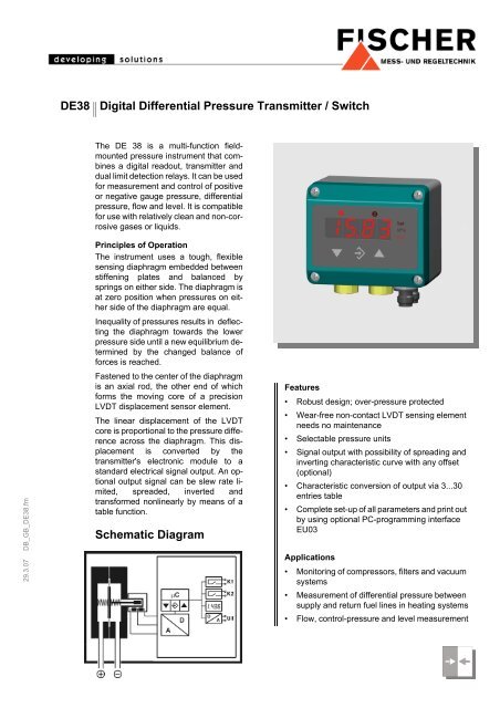
The DE 38 is a multi-function fieldmounted<br />
pressure instrument that combines<br />
a digital readout, transmitter and<br />
dual limit detection relays. It can be used<br />
for measurement and control of positive<br />
or negative gauge pressure, differential<br />
pressure, flow and level. It is compatible<br />
for use with relatively clean and non-corrosive<br />
gases or liquids.<br />
Principles of Operation<br />
The instrument uses a tough, flexible<br />
sensing diaphragm embedded between<br />
stiffening plates and balanced by<br />
springs on either side. The diaphragm is<br />
at zero position when pressures on either<br />
side of the diaphragm are equal.<br />
Inequality of pressures results in deflecting<br />
the diaphragm towards the lower<br />
pressure side until a new equilibrium determined<br />
by the changed balance of<br />
forces is reached.<br />
Fastened to the center of the diaphragm<br />
is an axial rod, the other end of which<br />
forms the moving core of a precision<br />
LVDT displacement sensor element.<br />
The linear displacement of the LVDT<br />
core is proportional to the pressure difference<br />
across the diaphragm. This displacement<br />
is converted by the<br />
transmitter's electronic module to a<br />
standard electrical signal output. An optional<br />
output signal can be slew rate limited,<br />
spreaded, inverted and<br />
transformed nonlinearly by means of a<br />
table function.<br />
<strong>Schematic</strong> <strong>Diagram</strong><br />
Features<br />
• Robust design; over-pressure protected<br />
• Wear-free non-contact LVDT sensing element<br />
needs no maintenance<br />
• Selectable pressure units<br />
• Signal output with possibility of spreading and<br />
inverting characteristic curve with any offset<br />
(optional)<br />
• Characteristic conversion of output via 3...30<br />
entries table<br />
• Complete set-up of all parameters and print out<br />
by using optional PC-programming interface<br />
EU03<br />
Applications<br />
• Monitoring of compressors, filters and vacuum<br />
systems<br />
• Measurement of differential pressure between<br />
supply and return fuel lines in heating systems<br />
• Flow, control-pressure and level measurement
Specifications<br />
General<br />
Measuring mbar 0-400 0-600 0-1000 0-1600<br />
range<br />
max. static<br />
bar 0-1.000 0-1.600 0-2.50 0-4.00 0-6.00<br />
operating pressure<br />
bar 16 bar<br />
straight line<br />
error (max.)°<br />
%FS 2.5 %<br />
Straight line<br />
error (typ.)°<br />
%FS 0.8 %<br />
Tc span<br />
(max.)°°<br />
%FS<br />
10K<br />
0.8 % 0.4 %<br />
Tc span (typ.)°° %FS<br />
10K<br />
0.2 %<br />
Tc zero point<br />
(max.)°°<br />
%FS<br />
10K<br />
0.8 % 0.5 %<br />
Tc zero point<br />
(typ.)°°<br />
%FS<br />
10K<br />
0.2 %<br />
Operating temp. (ambient)<br />
Operating temp. (media)<br />
Storage temperature<br />
Protection class (housing)<br />
Nominal supply voltage<br />
Operating supply voltage<br />
Output signal<br />
-10 … 70°C<br />
-10 … 70°C<br />
-20 … 70°C<br />
IP 65 per DIN EN 60529<br />
Electrical<br />
24 V DC/AC<br />
12 … 32 V DC/AC<br />
0 … 20 mA, 4 … 20 mA, 0 … 10 V (3-wire)<br />
°: Straight line error = nonlinearity<br />
+ hysteresis; at<br />
25°C; pressure within specified<br />
range (characteristic<br />
linear, not spreaded)<br />
°°: <strong>Pressure</strong> within specified<br />
range (characteristic linear,<br />
not spreaded);<br />
compensated temperature<br />
range 0 to 60°C<br />
Output signal load For output current RL ≤ (UB - 4 V) / 0.02 A (UB ≤ 26V), else RL ≤ 1100 Ω<br />
For output voltage RL ≥ 2 KΩ (UB ≥ 15 V), RL ≥ 10 KΩ (UB = 12 …15V)<br />
Power consumption Approx. 2 W/VA<br />
Switching contacts 2 sets of programmable voltage free relay contacts: NO or NC<br />
Umax = 32 V DC/AC, Imax = 2 A, Pmax = 64 W/VA<br />
Optional, instead of relay outputs:<br />
2 programmable voltage free MOSFET switch outputs; NO/NC<br />
U = 3 … 32 V DC/AC, Imax = 0.25 A, Pmax = 8 W/VA, RON ≤ 4 Ω<br />
Display 3½ digit LED<br />
Connections<br />
Electrical connections Two round-shell multi-pin connector sockets (M12, male)<br />
Connector 1: 5-pin: power input and analog signal output<br />
Connector 2: 4-pin: relay contacts / solid-state switch outputs<br />
<strong>Pressure</strong> connections G 1/8 female threads with optional cutting ring fittings for 6 or 8 mm tube<br />
Materials, Mounting<br />
Materials, housing Polyamid PA 6.6<br />
Materials, media contact Brass, VITON ® , NBR<br />
Mounting Rear mounting holes for panel mounting<br />
Wall mountable using adaptor plate<br />
IIf the instrument is intended for outdoor application, we highly recommend using an<br />
adequate protective housing (or at least a big enough shelter) as permanent protection<br />
against UV-radiation on the membrane keyboard and against exposure of the<br />
instrument to rain or snow.
Dimensions (all units in mm unless stated otherwise)<br />
G1/8 female<br />
Programming<br />
Cutting ring fittings for 6 or 8 mm tubes<br />
Wall mounting adaptor<br />
plate (optional)<br />
Via membrane key-switches or by using PC-programming interface (accessory), programming mode can be password<br />
protected.<br />
Settings:<br />
Input filtering 0.0 ... 100.0 secs (10 / 90% step response time)<br />
Relay / switch 1 / 2 activation point, de-activation point, response time delay (0.0 ... 100.0 secs),<br />
logic (N/O or N/C)<br />
Measurement unit selection bar, kPa, psi<br />
Zero suppression 0 ... 100 counts (1)<br />
Output signal start / end value can be set at any point of measuring range (2)<br />
Zero pressure calibration ±100 counts (3)<br />
M 12 connector Holes for sheet metal<br />
connector 2<br />
connector 1<br />
screws: 3.5 mm dia.<br />
Electrical connection /<br />
Switching function<br />
Output characteristic linear, square rooted, horizontal cylindr. tank, table (3...30 entries)<br />
Password range 001 ... 999 (000 = password protection disabled)<br />
Rear view<br />
without wall mounting adaptor plate<br />
(standard)<br />
Notes:<br />
(1) Measured value deviations up to 100 counts symmetric about zero are set to zero. Used for zero drift suppression.<br />
(2) Maximum effective turn-down ratio = 4:1. Only the output signal is affected. Transfer function is inverted if start value > end value.<br />
(3) Zero calibration setting may change with mounting orientation.
Ordering Code<br />
<strong>Digital</strong> <strong>Differential</strong> <strong>Pressure</strong><br />
<strong>Transmitter</strong> / Switch DE 38<br />
Measuring range<br />
0 . . 400 mbar ...................................................................... 8 3<br />
0 . . . . 0.6 bar...................................................................... 0 1<br />
0 . . . . 1 bar...................................................................... 0 2<br />
0 . . . . 1.6 bar...................................................................... 0 3<br />
0 . . . . 2.5 bar...................................................................... 0 4<br />
0 . . . . 4 bar...................................................................... 0 5<br />
0 . . . . 6 bar......................................................................<br />
Sensor materials<br />
0 6<br />
<strong>Pressure</strong> chambers, diaphragm, gaskets: brass / NBR ...................... M<br />
<strong>Pressure</strong> chambers, diaphragm, gaskets: brass / Viton ® ....................<br />
<strong>Pressure</strong> connections<br />
N<br />
G 1/8 female thread ............................................................................................ 0 0<br />
Brass cutting ring fitting for 6 mm tube................................................................ 2 8<br />
Brass cutting ring fitting for 8 mm tube................................................................<br />
Signal output<br />
2 9<br />
No signal output .................................................................................................................. 0<br />
Current output: 0 - 20 mA linear, 3-wire .............................................................................. A<br />
Voltage output: 0 - 10 V DC linear, 3-wire ........................................................................... C<br />
Current output: 4 - 20 mA linear, 3-wire ..............................................................................<br />
Supply voltage<br />
P<br />
24 V DC/AC (12-32 V DC/AC) ...................................................................................................<br />
Display and limit switching points<br />
K<br />
3½ digit LED display; 2 sets of potential-free relay contacts...................................................................... 3<br />
3½ digit LED display; 2 solid-state switch outputs .....................................................................................<br />
Electrical connections<br />
6<br />
M12 roundshell multi-pin connectors .................................................................................................................<br />
Mounting<br />
M<br />
Rear fastening holes .................................................................................................................................................. 0<br />
Wall mounting ............................................................................................................................................................ W<br />
Accessories<br />
0 K 0 M<br />
Ordering code Designation Pins Application Length<br />
06401993 cable with M12 connector 4-pin for relay / switch 2 m<br />
06401994 cable with M12 connector 4-pin for relay / switch 5 m<br />
06401995 cable with M12 connector 5-pin for supply / signal 2 m<br />
06401996 cable with M12 connector 5-pin for supply / signal 5 m<br />
04005144 wall mounting adapter set<br />
EU03.F300 PC-programming interface with SW<br />
Technische Änderungen vorbehalten • Subject to change without notice • Changements techniques sous réserve<br />
Fischer Mess- und Regeltechnik GmbH • Bielefelder Str. 37a • D-32107 Bad Salzuflen • Tel. +49 5222 9740 • Fax +49 5222 7170 • eMail: info@fischermesstechnik.de • www.fischermesstechnik.de


