T E S T R E P O R T - Binderholz
T E S T R E P O R T - Binderholz
T E S T R E P O R T - Binderholz

You also want an ePaper? Increase the reach of your titles
YUMPU automatically turns print PDFs into web optimized ePapers that Google loves.
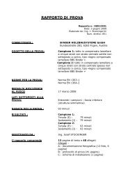
T E S T R E P O R T<br />
Test report no.: 08012901<br />
Date: June 3, 2008<br />
Official in charge: Ing. J. Stockinger/hi<br />
Extension: 851<br />
CLIENT: BINDER HOLZBAUSYSTEME GmbH<br />
Bundesstraße 283<br />
6263 Fügen, Austria<br />
TEST SPECIMEN: Sample 1: unstressed five-ply crosslaminated<br />
timber ceiling with thin<br />
intermediate ply, type: “Binder crosslaminated<br />
timber BBS”<br />
Sample 2: unstressed five-ply crosslaminated<br />
timber ceiling with thick<br />
intermediate ply, type: “Binder crosslaminated<br />
timber BBS”<br />
TEST PRINCIPLES: Standard EN 1363, section 1<br />
Standard EN 1364, section 2<br />
FIRE TEST: March 17, 2008<br />
SIDES SUBJECTED TO FLAME: for both samples: bottom side<br />
(symmetrical structure)<br />
DURATION OF TEST: 93 minutes<br />
TEST RESULTS: Sample 1:<br />
Integrity (E): 79 minutes<br />
Insulation (I): 79 minutes<br />
Sample 2:<br />
Integrity (E): 93 minutes<br />
Insulation (I): 93 minutes<br />
CARRIED OUT BY: Ing. Josef STOCKINGER<br />
This test report encompasses: 13 pages of text and 48 attachments<br />
Attachments:<br />
A: photo documentation (12<br />
photographs, 6 pages)<br />
B: test protocol (41 pages)<br />
C: engineering drawing (1 page)
TABLE OF CONTENTS<br />
1. Test principles............................................................................................................. 3<br />
2. Objective/test program ........................................................................................ 3<br />
3. Constructor/elaborator......................................................................................... 3<br />
4. Manufacturer of the materials used .............................................................. 3<br />
5. Sample taking ............................................................................................................. 4<br />
6. Description of the samples.................................................................................. 4<br />
6.1. Sample 1: Five-ply cross-laminated timber ceiling with thin<br />
intermediate ply.................................................................................. 4<br />
6.2. Sample 2: Five-ply cross-laminated timber ceiling with thick<br />
intermediate ply.................................................................................. 5<br />
7. Conditioning of the samples............................................................................... 7<br />
8. Mounting of samples............................................................................................... 7<br />
9. Description of test procedure............................................................................ 7<br />
9.1. Position of the side subjected to the flames ...................................... 7<br />
9.2. Ambient temperature .................................................................... 7<br />
9.3. Heating of the combustion chamber ................................................ 7<br />
9.5. Measuring of temperature in combustion chamber............................. 8<br />
9.6. Pressure in the combustion chamber ............................................... 8<br />
9.7. Measuring the temperature on the side of the samples facing away from<br />
the fire ……………………………………………………………………………………………………………..8<br />
9.8. Measuring the deformations on the side of the sample facing away from<br />
the fire ………………………………………………………………………………………………………………9<br />
10. Observations during and after the fire test .............................................. 9<br />
10.1. Test protocol .............................................................................. 9<br />
10.2. Findings after conclusion of test ...................................................10<br />
11. Comparison of the test samples with the standard criteria.......... 10<br />
12. Determination of combustion rate ............................................................... 11<br />
13. Direct area of application................................................................................... 12<br />
14. Remarks........................................................................................................................ 12
1. Test principles<br />
Standard EN 1363, section 1:<br />
“Fire resistance tests - section 1: General requirements”<br />
Version: January 1, 2000<br />
Standard EN 1364, section 2:<br />
“Fire resistance tests for nonload-bearing components - section 1: suspended<br />
ceilings”<br />
Version: April 1, 2000<br />
2. Objective/test program<br />
To determine the duration of fire resistance of the client’s nonload-bearing<br />
five-ply cross-laminated timber ceiling with thin or thick intermediate ply, a<br />
fire test was conducted in the test laboratory of IBS Linz on March 17, 2008.<br />
The connection of the individual ceiling components was done by means of<br />
inserted tongues. Two samples were tested simultaneously. They were<br />
checked and evaluated with regard to their integrity as well as to insulation<br />
criteria, in particular at the individual joint formations. Moreover the<br />
remaining section of each sample (five-ply structure with thin or thick<br />
intermediate ply) is to be determined in order to define a rate of combustion<br />
for the components.<br />
3. Constructor/elaborator<br />
Manufacturer: BINDER HOLZBAUSYSTEME, Bundesstraße 283, A- 6263<br />
Fügen, Austria<br />
Type: “Binder cross-laminated timber BBS”<br />
4. Manufacturer of the materials used<br />
Wooden parts<br />
Manufacturer: BINDER HOLZBAUSYSTEME, Bundesstraße 283, A- 6263<br />
Fügen, Austria<br />
Material: spruce, classification*): S10 for the longitudinal plies, ungraded<br />
wood is used for the cross plies; density: ~470kg/m3, average wood<br />
humidity: 12%<br />
*) Extract from the authorization of Binder company:<br />
At least 90% of the individual planks (lamellas) of the plies parallel to the<br />
component’s longitudinal axis have to correspond at least to the strength<br />
class of C 24 according to EN 338-9; the remaining planks have to<br />
correspond at least to strength class of C 16.
At least 30% of the individual planks of the cross plies have to correspond at<br />
least to the strength class of C 24; the remaining planks have to correspond<br />
at least to strength class of C 16.<br />
Glue for the cross-laminated timber gluing, surface<br />
Manufacturer: PURBOND AG, CH-6203 Sempach Station, Switzerland<br />
Type: “PURBOND HB 230,” amount to be applied: ~300 g/m 2<br />
Glue for the cross-laminated timber gluing, joints<br />
Manufacturer: CASCO Adhesive AB, PO Box 11538, SE-10061 Stockholm,<br />
Sweden<br />
Type: “1247,” with hardener “2526,” MUF glue<br />
External tongue<br />
Manufacturer: Franz BINDER GmbH, Gewerbegebiet 2, A-5113 St. Georgen<br />
bei Salzburg, Austria<br />
Material: spruce, three-ply glued, classification: at least 94% S10, the rest<br />
S7, density: ~470 kg/m 3 , average wood humidity: 12%<br />
Gluing of external tongue<br />
Manufacturer: Vinzenz HARRER GmbH, Badl 31, A-8130 Frohnleiten, Austria<br />
Type: “DENSLY ROOF,” amount to be applied: ~ 300g/m 2<br />
5. Sample taking<br />
Individual ceiling panels were delivered and correspondingly labeled by the<br />
client. As the panels were initially assembled in the test laboratory, no<br />
additional sample was requested by the test bureau for sample analysis<br />
(checking the materials used and their dimensions). Thicknesses and<br />
dimensions of the materials were verified prior to the fire test. No<br />
discrepancies with regard to the client’s specifications and his engineering<br />
drawings could be determined. Hence, these drawings could be adopted by<br />
the test bureau; they are attached as a copy to the test report (attachment<br />
C).<br />
6. Description of the samples<br />
6.1. Sample 1: Five-ply cross-laminated timber ceiling with thin<br />
intermediate ply<br />
6.1.1. Dimensions<br />
Total structure<br />
Total ceiling: 4000 x 4400mm (w x h)
Total ceiling subjected to flames: 4000 x 4000mm (w x h)<br />
Total ceiling, five-ply thin intermediate ply: 2000 x 4400mm (w x h)<br />
Total ceiling, five-ply thin intermediate ply, subjected to flames: 2000 x<br />
4000mm (w x h)<br />
Dimensions of individual panel: 750mm x 4400mm (w x h) or 1250 x 4400<br />
(w x h)<br />
Thickness: 146mm (individual thickness of each ply: 1st ply: 41mm, 2nd ply:<br />
21mm, 3rd ply: 22mm, 4th ply: 21mm, 5th ply: 41mm)<br />
6.1.2. General description of sample<br />
The sample was composed of two separate components. Each ceiling<br />
component consisted of five crosswise glued cross-laminated timber plies in<br />
all. The surfaces of the individual cross-laminated timber plies were glued<br />
throughout with PUR glue. The individual planks of the respective longitudinal<br />
ply were joined at the narrow side with a FUM glue. Then the visible surface<br />
was planed. The individual panels were butt joined.<br />
The individual ceiling components were connected among one another with<br />
an external tongue (27 x 110mm) on the upper side. The groove dimensions<br />
in the panels for that were 28 x 56mm. The external tongue was fastened to<br />
the individual components by dint of gluing and staggered bolting (counter<br />
sunk bolts 6 x 85mm, max. bolting distance to one another: approx.<br />
125mm). The pasty glue for gluing the external tongue was applied in the<br />
form of two sinuous lines (diameter: approx. 10mm).<br />
6.2. Sample 2: Five-ply cross-laminated timber ceiling with thick<br />
intermediate ply<br />
6.2.1. Dimensions<br />
Total structure<br />
Total ceiling: 4000 x 4400mm (w x h)<br />
Total ceiling subjected to flames: 4000 x 4000mm (w x h)<br />
Total ceiling, five-ply thick intermediate ply: 2000 x 4400mm (w x h)<br />
Total ceiling, five-ply thick intermediate ply, subjected to flames: 2000 x<br />
4000mm (w x h)<br />
Dimensions of individual panel: 750 x 4400mm (w x h) or 1250 x 4400 (w x<br />
h)<br />
Thickness: 125mm (individual thickness of each ply: 1st ply: 20mm, 2nd ply:<br />
21mm, 3rd ply: 43mm, 4th ply: 21mm, 5th ply: 20mm)
6.2.2. General description of sample<br />
The sample was composed of two separate components. Each ceiling<br />
component consisted of five crosswise glued cross-laminated timber plies in<br />
all. The surfaces of the individual cross-laminated timber plies were glued<br />
throughout with PUR glue. The individual planks of the respective longitudinal<br />
plies were joined at the narrow side with a FUM glue. Then the visible surface<br />
was planed. The individual panels were butt joined.<br />
The individual ceiling components were connected among one another with<br />
an external tongue (27 x 110mm) on the upper side. The groove dimensions<br />
in the panels for that were 28 x 56mm. The external tongue fastened to the<br />
individual component by dint of gluing and staggered bolting (counter sunk<br />
bolts 6 x 85mm, max. bolting distance to one another: approx. 125mm). The<br />
pasty glue for gluing the external tongue was applied in the form of two<br />
sinuous lines (diameter: approx. 10mm).<br />
The connection between the five-ply ceiling component with thick or thin<br />
intermediate ply was made by means of an inserted tongue that has been<br />
glued and bolted (27 x 110mm).
7. Conditioning of the samples<br />
The ceiling panels were delivered and mounted in the concrete test frame<br />
five days prior to the test date and were stored horizontally in the test<br />
laboratory. The ambient conditions at the time stood at approx. 20°C and<br />
60% relative humidity. Just before the fire test, the wood humidity was<br />
randomly measured at a total of 10 different places of the ceiling component.<br />
In so doing, a wood humidity within the range of 5.8% to 10.3% was<br />
determined.<br />
8. Mounting of samples<br />
The mounting of the samples was conducted by the client’s staff directly on<br />
the horizontal test oven prior to the fire test.<br />
The individual ceiling components were placed successively on the horizontal<br />
test bench and joined among one another by means of glued and bolted<br />
external tongues. The sealing of the edge joints was done on the four sides<br />
by means of mineral wool strips, plus on both longitudinal sides by additional<br />
porous concrete stones.<br />
9. Description of test procedure<br />
9.1. Position of the side subjected to the flames<br />
The samples were arranged symmetrically and subjected to flames from<br />
underneath.<br />
9.2. Ambient temperature<br />
The ambient temperature was continuously recorded by a type K thermal<br />
element with a thickness of 3mm during the entire time of the test. The<br />
measuring was conducted at the measuring unit, which was situated at an<br />
adequate distance from the test oven. The temperatures are reported in the<br />
enclosed test protocol (attachment B).<br />
9.3. Heating of the combustion chamber<br />
The heating of the combustion chamber was effected with extra light fuel for<br />
ovens.<br />
9.4. Temperature in the combustion chamber<br />
Standard temperature curve according to standard EN 1363, section 1,<br />
article 5.1.1.
9.5. Measuring of temperature in combustion chamber<br />
Eight plate thermometers conforming to standard EN 1363, section 1, article<br />
4.5.1.1, using NiCr-Ni thermal elements (type K) with a wire diameter of<br />
1mm. The thermal elements were inserted so far into the combustion<br />
chamber as to be able to measure the sample surface subjected to the<br />
flames evenly.<br />
Distance between the samples and the plate thermometers: approx. 100mm.<br />
9.6. Pressure in the combustion chamber<br />
The pressure in the combustion chamber was regulated in such a way that<br />
20 Pa is not exceeded 100mm underneath the bottom side of the sample.<br />
The results are reported in attachment B.<br />
9.7. Measuring the temperature on the side of the samples facing<br />
away from the fire<br />
To detect rises of temperature on the side of the structure facing away from<br />
the fire, compared to the initial values, NiCrNi thermal elements conforming<br />
to standard EN 1363, section 1, article 4.5.1.2 (type K, wire diameter<br />
0.5mm) were applied to the samples, in an arrangement according to the<br />
attached test protocols: “Thermal elements on the side facing away from the<br />
fire.”<br />
Each thermal element was covered by an inorganic heat-insulating covering<br />
(density: approx. 900 kg/m 3 ), measuring 30 x 30mm, and glued onto the<br />
samples (type of glue: “Furtol Kernkleber”).<br />
Additionally, core hole drillings were made at every ply depth. In these core<br />
holes, NiCr-Ni thermal elements (type K, wire diameter 1mm) were inserted<br />
to detect the temperatures in these areas. The designations (L1 to L5 for the<br />
five-ply ceiling structure with thick intermediate ply [here a supplementary<br />
thermal element was inserted into the middle of the intermediate ply] or L1<br />
to L4 for five-ply ceiling structure with thin intermediate ply) on the diagram<br />
of measuring points mean as follows: L1 is the first ply joint as seen from the<br />
side facing the fire, L2 is the second ply joint and so on.<br />
The temperature rises detected on the side facing away from the fire,<br />
compared to the initial values, were recorded by the measuring unit and are<br />
reported in attachment B.
9.8. Measuring the deformations on the side of the sample facing<br />
away from the fire<br />
Due to the test program drawn up together with the client, no deformations<br />
were measured (see Item 2 of this test report).<br />
10. Observations during and after the fire test<br />
10.1. Test protocol<br />
During the fire test on March 17, 2008, the following modifications were<br />
detected on the cold side:<br />
15th test minute:<br />
Slight smoke discharges from the joints were discernible.<br />
30th test minute:<br />
Yellow surface discolorations around the butt joints were partially discernible.<br />
55th test minute:<br />
Sporadic fissures with nearly indiscernible smoke discharges appeared on the<br />
surface of the five-ply component.<br />
75th test minute:<br />
In the joint area (joint 1) of the ceiling component with thick intermediate<br />
ply, a heightened smoke discharge could be observed.<br />
80th test minute:<br />
In the joint area (joint 2) at the transition of the two ceiling structures,<br />
persistent flames formed (more than 10 seconds). The flames were then<br />
extinguished. Hence, this joint formation was negative.<br />
84th test minute:<br />
In the joint area (joint 1) of the ceiling component with thick intermediate<br />
ply, a persistent flame formation (more than 10 seconds) could be observed.<br />
Hence, this joint formation was negative.<br />
93rd test minute:<br />
At the client’s request and as a result of the failure of the integrity, the fire<br />
test was terminated. After three minutes and 20 seconds, the flames on the<br />
sample were completely extinguished.
10.2. Findings after conclusion of test<br />
10.2.1 State of the sample as a whole on the side facing away from the fire<br />
In the area of the persistent flame formation, signs of wood combustion were<br />
visible. Otherwise no obvious modifications were observable.<br />
10.2.2. State of the samples on the side facing the fire<br />
Typical signs of wood combustion were visible. The charred plies partly fell<br />
off by themselves or as a result of extinguishing the flames. The external<br />
tongues were partly charred.<br />
11. Comparison of the test samples with the standard<br />
criteria<br />
Remark: The temperature values listed in the table are those values that<br />
were prevailing at the time of the failure of the integrity.<br />
Reference<br />
standard<br />
Performance<br />
criterion<br />
Criterion of<br />
failure<br />
17/03/2008<br />
Sample 1<br />
Five-ply<br />
structure, thin<br />
intermediate<br />
ply<br />
17/03/2008<br />
Sample 2<br />
Five-ply<br />
structure, thick<br />
intermediate<br />
ply<br />
1 --- --- --- Entire duration of<br />
test<br />
93 minutes 93 minutes<br />
2 Combustion of<br />
cotton wool ball<br />
took place not not<br />
3 Penetration of the The feeler gauge not done not done<br />
sample by the 6- could be moved<br />
mm feeler gauge in a crack<br />
standard<br />
150mm<br />
4 EN 1363-1,<br />
Penetration of the The feeler gauge not done not done<br />
article 11.2<br />
E sample by the 25mm<br />
feeler gauge<br />
could penetrate<br />
the sample<br />
5<br />
Flames on the side Flames > 10 sec. none 80 minutes<br />
facing away from on the side facing<br />
the fire<br />
away from the<br />
fire<br />
6<br />
Exceeding of the<br />
admissible average<br />
rise of temperature<br />
above the initial<br />
Test minute No exceeding No exceeding<br />
7 standard<br />
EN 1363-1 I<br />
temperature on the<br />
side of the sample<br />
Max. T –<br />
average in K<br />
0.0 0.8<br />
article 11.3.a Average rise facing away from<br />
of<br />
the fire<br />
temperature Max. admissible<br />
average = 140 K<br />
8<br />
Exceeding of the<br />
admissible<br />
Test minute No exceeding No exceeding<br />
9<br />
standard<br />
maximum rise of<br />
temperature above<br />
the initial<br />
at the measuring<br />
point<br />
12 18<br />
10<br />
EN 1363-1<br />
article 11.3.b<br />
I<br />
temperature on the<br />
side of the sample<br />
facing away from<br />
T in K 2.2 10.8<br />
Max. rise of<br />
the fire
temperature Surface:<br />
Max. admissible<br />
individual value<br />
= 180 K<br />
11 Ambient<br />
12<br />
13<br />
standard<br />
EN 1363-1<br />
article 5.6<br />
standard<br />
EN 1363-1<br />
article 9.2<br />
Oven<br />
pressure<br />
temperature at the<br />
start of test<br />
T max. = + 20 K<br />
T min = -5 K<br />
Pressure in the<br />
combustion<br />
chamber measured<br />
at the upper edge<br />
of the test chamber<br />
in °C 18.1<br />
T in K + 1.7<br />
in Pa 17-21<br />
In the present fire test, in the case of the component with five-ply structure<br />
and thick intermediate ply, the integrity failed after 80 minutes. Insulation<br />
was conserved until the failure of integrity.<br />
12. Determination of combustion rate<br />
The following procedure has been selected to determine the combustion rate:<br />
Additional small samples (1500 x 1500mm, surface subjected to the flames:<br />
1200 x 1200mm) were exposed to the flames for a period of 30 minutes,<br />
according to the conditions of standard EN 1363, section I. Then strips<br />
measuring 100mm in width were cut in the direction of the longitudinal plies<br />
by means of a circular saw; the respective remaining section was determined<br />
at the cutting area in intervals of 100mm. This resulted in an average<br />
remaining section of 122.76mm for the five-ply ceiling structure with thin<br />
intermediate ply and the remaining section of 101.75mm for the five-ply<br />
ceiling structure with thick intermediate ply.<br />
Summary:<br />
Five-ply structure with Five-ply structure with<br />
thin intermediate ply thick intermediate ply<br />
Total thickness of<br />
component<br />
146mm 125mm<br />
Average remaining<br />
section<br />
122.76mm 101.75mm<br />
Total duration of fire *) 31 minutes and 17 31 minutes and 22<br />
seconds<br />
seconds<br />
Combustion rate 0.74 mm/min. 0.74 mm/min.<br />
*) The total duration of the fire is defined as follows: the total duration of the<br />
fire is comprised of the time the sample is subjected to the flames by means<br />
of the burners according to standard EN 1363, section 1, and the time until<br />
the flames on the side of the component facing the fire have been completely<br />
extinguished.
13. Direct area of application<br />
The results of the fire test are directly applicable to similar constructions for<br />
which one or more of the following modifications have been made:<br />
- an enlargement of the thickness of the ceiling is an option<br />
- reduction of the distance between fixing points<br />
- a widening of the ceiling is possible<br />
- the joint formations subjected to test for the respective duration of<br />
fire resistance are admissible.<br />
14. Remarks<br />
The present test report describes in detail the procedure for creating or<br />
mounting, the test conditions as well as the results that were attained with<br />
the component described here after it had been tested by the procedure<br />
indicated according to standards EN 1363, section 1, and to EN 1364, section<br />
2. Any major deviation in terms of the size and of construction details are<br />
not covered in this test report, with the exception of the deviations that are<br />
admissible in the relevant test procedure for direct area of application. Owing<br />
to the particular nature of the tests of the duration of fire resistance and the<br />
resulting difficulty in quantifying the uncertainties of measuring the duration<br />
of fire resistance, it is not possible to report a precisely defined degree of<br />
exactitude for the result. The present test report must be utilized only in an<br />
unabridged form and in conjunction with the listed attachments as so<br />
indicated.<br />
IBS-Institut für Brandschutztechnik und Sicherheitsforschung<br />
Gesellschaft m.b.H.<br />
(IBS Institute for Fire Protection Engineering and Safety Research,<br />
Limited)<br />
Governmental Accredited Test Center and Regulatory Agency<br />
Ing. Josef STOCKINGER<br />
Official in Charge<br />
Ing. Josef KRAML<br />
Divisional Head of the Test Center<br />
and Regulatory Agency<br />
Prok. Dipl.-Ing. Thomas TRAUNER<br />
Authorized Signatory<br />
Dir.-Stv. Ing. Helmut PEHERSTORFER<br />
Authorized Signatory<br />
Managing Director
[Beilage A: Seite 1 von 6]<br />
Fig. 1: The joint formation used as well as the gluing of the external tongue.<br />
Fig. 2: The samples at the start of the fire test on March 17, 2008.<br />
[2]<br />
Fig. 3: The state of the samples in the 20th test minute.<br />
Fig. 4: State of the samples in the 30th test minute.<br />
[3]<br />
Fig. 5: State of the samples in the 45th test minute.<br />
Fig. 6: State of the samples in the 60th test minute.<br />
[4]<br />
Fig. 7: State of the samples in the 75th test minute.<br />
Fig. 8: Persistent flame formation at joint 2 in the 80th test minute.<br />
[5]<br />
Fig. 9: State of the samples in the 90th test minute.<br />
Fig. 10: General view of the samples on the side facing away from the fire<br />
immediately subsequent to conclusion of test.<br />
[6]<br />
Fig. 11: General view of the sample with thick intermediate ply on the side<br />
facing the fire subsequent to conclusion of test.<br />
Fig. 12: General view of the sample with the thin intermediate ply on the<br />
side facing the fire subsequent to conclusion of test.
[Blatt 1 von 41]<br />
German English<br />
Temperaturmesspunkte an der feuerabgewandten<br />
Seite<br />
Binder Brettsperrholz Decke<br />
Temperature measuring points on the side facing<br />
away from the fire<br />
Binder cross-laminated timber ceiling<br />
Fuge 1 Joint 1<br />
Fuge 2 Joint 2<br />
Fuge 3 Joint 3<br />
Fünflagiger Deckenaufbau<br />
dünne Mittellage<br />
Five-ply ceiling structure, thin intermediate ply<br />
Fünflagiger Wandaufbau<br />
Five-ply ceiling construction, thick intermediate<br />
dicke Mittellage<br />
ply<br />
(Skizzenmaßstab mit Probekörper nicht ident) (Scale of sketches is not identical to the sample)<br />
MESSPUNKTE ENTSPRECHEND ÖNORM EN 1364- MEASUREMENT POINTS CORRESPOND TO<br />
2<br />
STANDARD EN 1364-2<br />
Messpunkte 1 – 5 = Mittlere Temperatur dünne Measuring points 1 – 5 = average temperature,<br />
Mittellage<br />
thin intermediate ply<br />
Messpunkte 6 – 10 = Fuge 1 Measuring points 6 – 10 = joint 1
Messpunkte 11 – 13 = Mittlere Temperatur dicke Measuring points 11 – 13 = average temperature,<br />
Mittellage<br />
thick intermediate ply<br />
Messpunkte 14 – 17 = Fuge 3 Measuring points 14 – 17 = joint 3<br />
Messpunkte 18 – 21 = Fuge 2 Measuring points 18 – 21 = joint 2<br />
Messpunkte 22 – 25 = Lagen dünne Mittellage Measuring points 22 – 25 = plies, thin<br />
intermediate ply<br />
Messpunkte 25 – 30 = Lagen dicke Mittellage Measuring points 25 – 30 = plies, thick<br />
intermediate ply<br />
[unten]<br />
Versuchsdatum: 17.03.2008, gespeichert unter:<br />
bind1703.cdr<br />
Test date: March 17, 2008, filed at: bind1703.cdr<br />
Prüfbericht Nr.: 08012901, Beilage B:<br />
Versuchsprotokoll, Blatt 1 von 41<br />
Test report no.: 08012901, attachment B: test<br />
protocol, page 1 of 41
[2]<br />
Recording of temperature of the fire test in the oven and on the cold side of<br />
the sample<br />
Sample designation cross-laminated timber ceiling<br />
Subjected to flames bottom side<br />
Date of test March 17, 2008<br />
German English<br />
Ofen Oven<br />
Zeit Time<br />
Gesamtzeit [Min.] Total time [min.]<br />
Versuchszeit [Min.] Test time [min.]<br />
Ofen Sonde 1 [°C] Oven sensor 1 [°C]<br />
Ofen Sonde 2 [°C] Oven sensor 2 [°C]<br />
Ofen Sonde 3 [°C] Oven sensor 3 [°C]<br />
Ofen Sonde 4 [°C] Oven sensor 4 [°C]<br />
Ofen Sonde 5 [°C] Oven sensor 5 [°C]<br />
Ofen Sonde 6 [°C] Oven sensor 6 [°C]<br />
Ofen Sonde 7 [°C] Oven sensor 7 [°C]<br />
Ofen Sonde 8 [°C] Oven sensor 8 [°C]
[3]<br />
German English<br />
Ofen Oven<br />
Zeit Time<br />
Gesamtzeit [Min.] Total time [min.]<br />
Versuchszeit [Min.] Test time [min.]<br />
Ofen Sonde 1 [°C] Oven sensor 1 [°C]<br />
Ofen Sonde 2 [°C] Oven sensor 2 [°C]<br />
Ofen Sonde 3 [°C] Oven sensor 3 [°C]<br />
Ofen Sonde 4 [°C] Oven sensor 4 [°C]<br />
Ofen Sonde 5 [°C] Oven sensor 5 [°C]<br />
Ofen Sonde 6 [°C] Oven sensor 6 [°C]<br />
Ofen Sonde 7 [°C] Oven sensor 7 [°C]<br />
Ofen Sonde 8 [°C] Oven sensor 8 [°C]
[4]<br />
German English<br />
Ofen Oven<br />
Zeit Time<br />
Gesamtzeit [Min.] Total time [min.]<br />
Versuchszeit [Min.] Test time [min.]<br />
Ofen Sonde 1 [°C] Oven sensor 1 [°C]<br />
Ofen Sonde 2 [°C] Oven sensor 2 [°C]<br />
Ofen Sonde 3 [°C] Oven sensor 3 [°C]<br />
Ofen Sonde 4 [°C] Oven sensor 4 [°C]<br />
Ofen Sonde 5 [°C] Oven sensor 5 [°C]<br />
Ofen Sonde 6 [°C] Oven sensor 6 [°C]<br />
Ofen Sonde 7 [°C] Oven sensor 7 [°C]<br />
Ofen Sonde 8 [°C] Oven sensor 8 [°C]
[5]<br />
Pressure threshold for the pressure at the upper edge of sample: 20 Pa<br />
German English<br />
Ofen Oven<br />
Gesamtzeit [Min.] Total time [min.]<br />
Versuchszeit [Min.] Test time [min.]<br />
zul. pos. Abw. Ofensonde Admissible positive deviation, oven sensor<br />
zul. neg. Abw. Ofensonde Admissible negative deviation, oven sensor<br />
mittl. Sollwert [°C] Average target value [°C]<br />
mittl. Istwert [°C] Average actual value [°C]<br />
Hallentemp. [°C] Hall temperature [°C]<br />
Ofeninnendruck [Pa] Internal oven pressure [Pa]
[6]<br />
German English<br />
Ofen Oven<br />
Gesamtzeit [Min.] Total time [min.]<br />
Versuchszeit [Min.] Test time [min.]<br />
zul. pos. Abw. Ofensonde Admissible positive deviation, oven sensor<br />
zul. neg. Abw. Ofensonde Admissible negative deviation, oven sensor<br />
mittl. Sollwert [°C] Average target value [°C]<br />
mittl. Istwert [°C] Average actual value [°C]<br />
Hallentemp. [°C] Hall temperature [°C]<br />
Ofeninnendruck [Pa] Internal oven pressure [Pa]
[7]<br />
German English<br />
Ofen Oven<br />
Gesamtzeit [Min.] Total time [min.]<br />
Versuchszeit [Min.] Test time [min.]<br />
zul. pos. Abw. Ofensonde Admissible positive deviation, oven sensor<br />
zul. neg. Abw. Ofensonde Admissible negative deviation, oven sensor<br />
mittl. Sollwert [°C] Average target value [°C]<br />
mittl. Istwert [°C] Average actual value [°C]<br />
Hallentemp. [°C] Hall temperature [°C]<br />
Ofeninnendruck [Pa] Internal oven pressure [Pa]
[8]<br />
German English<br />
Ofen Oven<br />
Gesamtzeit [Min.] Total time [min.]<br />
Versuchszeit [Min.] Test time [min.]<br />
A-Ist [Min. °C] Actual A [min. °C]<br />
A-Soll [Min. °C] Target A [min. °C]<br />
Abweichung Deviation<br />
zul. positive Abweichung Admissible positive deviation<br />
zul. negative Abweichung Admissible negative deviation
[9]<br />
German English<br />
Ofen Oven<br />
Gesamtzeit [Min.] Total time [min.]<br />
Versuchszeit [Min.] Test time [min.]<br />
A-Ist [Min. °C] Actual A [min. °C]<br />
A-Soll [Min. °C] Target A [min. °C]<br />
Abweichung Deviation<br />
zul. positive Abweichung Admissible positive deviation<br />
zul. negative Abweichung Admissible negative deviation
[10]<br />
German English<br />
Ofen Oven<br />
Gesamtzeit [Min.] Total time [min.]<br />
Versuchszeit [Min.] Test time [min.]<br />
A-Ist [Min. °C] Actual A [min. °C]<br />
A-Soll [Min. °C] Target A [min. °C]<br />
Abweichung Deviation<br />
zul. positive Abweichung Admissible positive deviation<br />
zul. negative Abweichung Admissible negative deviation
[11]<br />
German English<br />
Ofen-Einzelsonden Individual oven sensors<br />
Temperatur in °C Temperature in °C<br />
Ofen Sonde 1 [°C] Oven sensor 1 [°C]<br />
Ofen Sonde 2 [°C] Oven sensor 2 [°C]<br />
Ofen Sonde 3 [°C] Oven sensor 3 [°C]<br />
Ofen Sonde 4 [°C] Oven sensor 4 [°C]<br />
Ofen Sonde 5 [°C] Oven sensor 5 [°C]<br />
Ofen Sonde 6 [°C] Oven sensor 6 [°C]<br />
Ofen Sonde 7 [°C] Oven sensor 7 [°C]<br />
Ofen Sonde 8 [°C] Oven sensor 8 [°C]<br />
zul. pos. Abw. Ofensonde Admissible positive deviation, oven sensor<br />
zul. neg. Abw. Ofensonde Admissible negative deviation, oven sensor<br />
Hallentemp. [°C] Hall temperature [°C]<br />
Zeit in Minuten Time in minutes
[12]<br />
German English<br />
Mittlere Ofentemperatur Average oven temperature<br />
Temperatur in °C Temperature in °C<br />
mittl. Sollwert [°C] Average target value [°C]<br />
mittl. Istwert [°C] Average actual value [°C]<br />
Zeit in Minuten Time in minutes
[13]<br />
German English<br />
Ofeninnendruck Internal oven pressure<br />
Druck. Diff. In Pascal Difference in pressure, in Pascal<br />
Druck PK Oberkante [Pa] Pressure, upper edge of sample [Pa]<br />
Druckgrenzwert für Druck an der PK Oberkante Pressure threshold for pressure at upper edge of<br />
sample<br />
Zeit in Minuten Time in minutes<br />
Abweichung der Kurvenfläche der mittleren Deviation of the curve area of the average oven<br />
Ofentemperatur<br />
temperature<br />
Abweichung Deviation<br />
zul. pos. Abweichung Admissible positive deviation<br />
zul. negative Abweichung Admissible negative deviation<br />
Abweichung in % Deviation in %<br />
Zeit in Minuten Time in minutes
[14]<br />
Max. rise in temperature for an individual value: 180 °C<br />
Max. rise in temperature for the average: 140 °C<br />
The values of measurements indicated are rises in temperature compared to<br />
the initial values.<br />
German English<br />
Mittlere Temperatur dünne Mittellage Average temperature, thin intermediate ply<br />
Gesamtzeit [Min.] Total time [min.]<br />
Versuchszeit [Min.] Test time [min.]<br />
Messpunkt 1 [°C] Measuring point 1 [°C]<br />
Messpunkt 2 [°C] Measuring point 2 [°C]<br />
Messpunkt 3 [°C] Measuring point 3 [°C]<br />
Messpunkt 4 [°C] Measuring point 4 [°C]<br />
Messpunkt 5 [°C] Measuring point 5 [°C]<br />
Durchschnitt Average
[15]<br />
Max. rise in temperature for an individual value: 180 °C<br />
Max. rise in temperature for the average: 140 °C<br />
The values of measurements indicated are rises in temperature compared to<br />
the initial values.<br />
German English<br />
Mittlere Temperatur dünne Mittellage Average temperature, thin intermediate ply<br />
Gesamtzeit [Min.] Total time [min.]<br />
Versuchszeit [Min.] Test time [min.]<br />
Messpunkt 1 [°C] Measuring point 1 [°C]<br />
Messpunkt 2 [°C] Measuring point 2 [°C]<br />
Messpunkt 3 [°C] Measuring point 3 [°C]<br />
Messpunkt 4 [°C] Measuring point 4 [°C]<br />
Messpunkt 5 [°C] Measuring point 5 [°C]<br />
Durchschnitt Average
[16]<br />
Max. rise in temperature for an individual value: 180 °C<br />
Max. rise in temperature for the average: 140 °C<br />
The values of measurements indicated are rises in temperature compared to<br />
the initial values.<br />
German English<br />
Mittlere Temperatur dünne Mittellage Average temperature, thin intermediate ply<br />
Gesamtzeit [Min.] Total time [min.]<br />
Versuchszeit [Min.] Test time [min.]<br />
Messpunkt 1 [°C] Measuring point 1 [°C]<br />
Messpunkt 2 [°C] Measuring point 2 [°C]<br />
Messpunkt 3 [°C] Measuring point 3 [°C]<br />
Messpunkt 4 [°C] Measuring point 4 [°C]<br />
Messpunkt 5 [°C] Measuring point 5 [°C]<br />
Durchschnitt Average
[17]<br />
German English<br />
Mittlere Temperatur dünne Mittellage Average temperature, thin intermediate ply<br />
Durchschnitt Average<br />
Max.-GW. Max. total value<br />
Durchschnitts-GW. Average total value<br />
Temperaturerhöhung in Celsius Rise in temperature in Celsius<br />
Zeit in Minuten Time in minutes
[18]<br />
Max. rise in temperature for an individual value: 180 °C<br />
The values of measurements indicated are rises in temperature compared to<br />
the initial values.<br />
German English<br />
Fuge 1 Joint 1<br />
Gesamtzeit [Min.] Total time [min.]<br />
Versuchszeit [Min.] Test time [min.]<br />
Messpunkt 11 [°C] Measuring point 11 [°C]<br />
Messpunkt 12 [°C] Measuring point 12 [°C]<br />
Messpunkt 13 [°C] Measuring point 13 [°C]<br />
Durchschnitt Average
[19]<br />
Max. rise in temperature for an individual value: 180 °C<br />
The values of measurements indicated are rises in temperature compared to<br />
the initial values.<br />
German English<br />
Fuge 1 Joint 1<br />
Gesamtzeit [Min.] Total time [min.]<br />
Versuchszeit [Min.] Test time [min.]<br />
Messpunkt 11 [°C] Measuring point 11 [°C]<br />
Messpunkt 12 [°C] Measuring point 12 [°C]<br />
Messpunkt 13 [°C] Measuring point 13 [°C]<br />
Durchschnitt Average
[20]<br />
Max. rise in temperature for an individual value: 180 °C<br />
The values of measurements indicated are rises in temperature compared to<br />
the initial values.<br />
German English<br />
Fuge 1 Joint 1<br />
Gesamtzeit [Min.] Total time [min.]<br />
Versuchszeit [Min.] Test time [min.]<br />
Messpunkt 11 [°C] Measuring point 11 [°C]<br />
Messpunkt 12 [°C] Measuring point 12 [°C]<br />
Messpunkt 13 [°C] Measuring point 13 [°C]<br />
Durchschnitt Average
[21]<br />
German English<br />
Fuge 1 Joint 1<br />
Durchschnitt Average<br />
Max.-GW. Max. total value<br />
Temperaturerhöhung in Celsius Rise in temperature in Celsius<br />
Zeit in Minuten Time in minutes
[22]<br />
Max. rise in temperature for an individual value: 180 °C<br />
Max. rise in temperature for the average: 140 °C<br />
The values of measurements indicated are rises in temperature compared to<br />
the initial values.<br />
German English<br />
Mittlere Temperatur dicke Mittellage Average temperature, thick intermediate ply<br />
Gesamtzeit [Min.] Total time [min.]<br />
Versuchszeit [Min.] Test time [min.]<br />
Messpunkt 6 [°C] Measuring point 6[°C]<br />
Messpunkt 7 [°C] Measuring point 7 [°C]<br />
Messpunkt 8 [°C] Measuring point 8[°C]<br />
Messpunkt 9 [°C] Measuring point 9[°C]<br />
Messpunkt 10 [°C] Measuring point 10[°C]<br />
Durchschnitt Average
[23]<br />
Max. rise in temperature for an individual value: 180 °C<br />
Max. rise in temperature for the average: 140 °C<br />
The values of measurements indicated are rises in temperature compared to<br />
the initial values.<br />
German English<br />
Mittlere Temperatur dicke Mittellage Average temperature, thick intermediate ply<br />
Gesamtzeit [Min.] Total time [min.]<br />
Versuchszeit [Min.] Test time [min.]<br />
Messpunkt 6 [°C] Measuring point 6[°C]<br />
Messpunkt 7 [°C] Measuring point 7 [°C]<br />
Messpunkt 8 [°C] Measuring point 8[°C]<br />
Messpunkt 9 [°C] Measuring point 9[°C]<br />
Messpunkt 10 [°C] Measuring point 10[°C]<br />
Durchschnitt Average
[24]<br />
Max. rise in temperature for an individual value: 180 °C<br />
Max. rise in temperature for the average: 140 °C<br />
The values of measurements indicated are rises in temperature compared to<br />
the initial values.<br />
German English<br />
Mittlere Temperatur dicke Mittellage Average temperature, thick intermediate ply<br />
Gesamtzeit [Min.] Total time [min.]<br />
Versuchszeit [Min.] Test time [min.]<br />
Messpunkt 6 [°C] Measuring point 6[°C]<br />
Messpunkt 7 [°C] Measuring point 7 [°C]<br />
Messpunkt 8 [°C] Measuring point 8[°C]<br />
Messpunkt 9 [°C] Measuring point 9[°C]<br />
Messpunkt 10 [°C] Measuring point 10[°C]<br />
Durchschnitt Average
[25]<br />
German English<br />
Mittlere Temperatur dicke Mittellage Average temperature, thick intermediate ply<br />
Durchschnitt Average<br />
Max.-GW. Max. total value<br />
Durchschnitts-GW. Average total value<br />
Temperaturerhöhung in Celsius Rise in temperature in Celsius<br />
Zeit in Minuten Time in minutes
[26]<br />
Max. rise in temperature for an individual value: 180 °C<br />
The values of measurements indicated are rises in temperature compared to<br />
the initial values.<br />
German English<br />
Fuge 2 Joint 2<br />
Gesamtzeit [Min.] Total time [min.]<br />
Versuchszeit [Min.] Test time [min.]<br />
Messpunkt 18 [°C] Measuring point 18[°C]<br />
Messpunkt 19 [°C] Measuring point 19 [°C]<br />
Messpunkt 20[°C] Measuring point 20[°C]<br />
Messpunkt 21 [°C] Measuring point 21[°C]<br />
Durchschnitt Average
[27]<br />
Max. rise in temperature for an individual value: 180 °C<br />
The values of measurements indicated are rises in temperature compared to<br />
the initial values.<br />
German English<br />
Fuge 2 Joint 2<br />
Gesamtzeit [Min.] Total time [min.]<br />
Versuchszeit [Min.] Test time [min.]<br />
Messpunkt 18 [°C] Measuring point 18[°C]<br />
Messpunkt 19 [°C] Measuring point 19 [°C]<br />
Messpunkt 20[°C] Measuring point 20[°C]<br />
Messpunkt 21 [°C] Measuring point 21[°C]<br />
Durchschnitt Average
[28]<br />
Max. rise in temperature for an individual value: 180 °C<br />
The values of measurements indicated are rises in temperature compared to<br />
the initial values.<br />
German English<br />
Fuge 2 Joint 2<br />
Gesamtzeit [Min.] Total time [min.]<br />
Versuchszeit [Min.] Test time [min.]<br />
Messpunkt 18 [°C] Measuring point 18[°C]<br />
Messpunkt 19 [°C] Measuring point 19 [°C]<br />
Messpunkt 20[°C] Measuring point 20[°C]<br />
Messpunkt 21 [°C] Measuring point 21[°C]<br />
Durchschnitt Average
[29]<br />
German English<br />
Fuge 2 Joint 2<br />
Durchschnitt Average<br />
Max.-GW. Max. total value<br />
Temperaturerhöhung in Celsius Rise in temperature in Celsius<br />
Zeit in Minuten Time in minutes
[30]<br />
Max. rise in temperature for an individual value: 180 °C<br />
The values of measurements indicated are rises in temperature compared to<br />
the initial values.<br />
German English<br />
Fuge 3 Joint 3<br />
Gesamtzeit [Min.] Total time [min.]<br />
Versuchszeit [Min.] Test time [min.]<br />
Messpunkt 14 [°C] Measuring point 14[°C]<br />
Messpunkt 15 [°C] Measuring point 15 [°C]<br />
Messpunkt 16[°C] Measuring point 16[°C]<br />
Messpunkt 17 [°C] Measuring point 17[°C]<br />
Durchschnitt Average
[31]<br />
Max. rise in temperature for an individual value: 180 °C<br />
The values of measurements indicated are rises in temperature compared to<br />
the initial values.<br />
German English<br />
Fuge 3 Joint 3<br />
Gesamtzeit [Min.] Total time [min.]<br />
Versuchszeit [Min.] Test time [min.]<br />
Messpunkt 14 [°C] Measuring point 14[°C]<br />
Messpunkt 15 [°C] Measuring point 15 [°C]<br />
Messpunkt 16[°C] Measuring point 16[°C]<br />
Messpunkt 17 [°C] Measuring point 17[°C]<br />
Durchschnitt Average
[32]<br />
Max. rise in temperature for an individual value: 180 °C<br />
The values of measurements indicated are rises in temperature compared to<br />
the initial values.<br />
German English<br />
Fuge 3 Joint 3<br />
Gesamtzeit [Min.] Total time [min.]<br />
Versuchszeit [Min.] Test time [min.]<br />
Messpunkt 14 [°C] Measuring point 14[°C]<br />
Messpunkt 15 [°C] Measuring point 15 [°C]<br />
Messpunkt 16[°C] Measuring point 16[°C]<br />
Messpunkt 17 [°C] Measuring point 17[°C]<br />
Durchschnitt Average
[33]<br />
German English<br />
Fuge 3 Joint 3<br />
Durchschnitt Average<br />
Max.-GW Max. total value<br />
Temperaturerhöhung in Celsius Rise in temperature in Celsius<br />
Zeit in Minuten Time in minutes
[34]<br />
The values of measurements indicated are rises in temperature compared to<br />
the initial values.<br />
German English<br />
Einzellage fünflagig dünne Mittellage Individual ply, five-ply, thin intermediate ply<br />
Gesamtzeit [Min.] Total time [min.]<br />
Versuchszeit [Min.] Test time [min.]<br />
Messpunkt 22 [°C] Measuring point 22[°C]<br />
Messpunkt 23 [°C] Measuring point 23 [°C]<br />
Messpunkt 24[°C] Measuring point 24[°C]<br />
Messpunkt 25 [°C] Measuring point 25[°C]<br />
Durchschnitt Average
[35]<br />
The values of measurements indicated are rises in temperature compared to<br />
the initial values.<br />
German English<br />
Einzellage fünflagig dünne Mittellage Individual ply, five-ply, thin intermediate ply<br />
Gesamtzeit [Min.] Total time [min.]<br />
Versuchszeit [Min.] Test time [min.]<br />
Messpunkt 22 [°C] Measuring point 22[°C]<br />
Messpunkt 23 [°C] Measuring point 23 [°C]<br />
Messpunkt 24[°C] Measuring point 24[°C]<br />
Messpunkt 25 [°C] Measuring point 25[°C]<br />
Durchschnitt Average
[36]<br />
The values of measurements indicated are rises in temperature compared to<br />
the initial values.<br />
German English<br />
Einzellage fünflagig dünne Mittellage Individual ply, five-ply, thin intermediate ply<br />
Gesamtzeit [Min.] Total time [min.]<br />
Versuchszeit [Min.] Test time [min.]<br />
Messpunkt 22 [°C] Measuring point 22[°C]<br />
Messpunkt 23 [°C] Measuring point 23 [°C]<br />
Messpunkt 24[°C] Measuring point 24[°C]<br />
Messpunkt 25 [°C] Measuring point 25[°C]<br />
Durchschnitt Average
[37]<br />
German English<br />
Einzellage fünflagig dünne Mittellage Individual ply, five-ply, thin intermediate ply<br />
Durchschnitt Average<br />
Temperaturerhöhung in Celsius Rise in temperature in Celsius<br />
Zeit in Minuten Time in minutes
[38]<br />
The values of measurements indicated are rises in temperature compared to<br />
the initial values.<br />
German English<br />
Einzellage fünflagig dicke Mittellage Individual ply, five-ply, thick intermediate ply<br />
Gesamtzeit [Min.] Total time [min.]<br />
Versuchszeit [Min.] Test time [min.]<br />
Messpunkt 26 [°C] Measuring point 26[°C]<br />
Messpunkt 27 [°C] Measuring point 27 [°C]<br />
Messpunkt 28[°C] Measuring point 28[°C]<br />
Messpunkt 29 [°C] Measuring point 29[°C]<br />
Messpunkt 30 [°C] Measuring point 30[°C]<br />
Durchschnitt Average
[39]<br />
The values of measurements indicated are rises in temperature compared to<br />
the initial values.<br />
German English<br />
Einzellage fünflagig dicke Mittellage Individual ply, five-ply, thick intermediate ply<br />
Gesamtzeit [Min.] Total time [min.]<br />
Versuchszeit [Min.] Test time [min.]<br />
Messpunkt 26 [°C] Measuring point 26[°C]<br />
Messpunkt 27 [°C] Measuring point 27 [°C]<br />
Messpunkt 28[°C] Measuring point 28[°C]<br />
Messpunkt 29 [°C] Measuring point 29[°C]<br />
Messpunkt 30 [°C] Measuring point 30[°C]<br />
Durchschnitt Average
[40]<br />
The values of measurements indicated are rises in temperature compared to<br />
the initial values.<br />
German English<br />
Einzellage fünflagig dicke Mittellage Individual ply, five-ply, thick intermediate ply<br />
Gesamtzeit [Min.] Total time [min.]<br />
Versuchszeit [Min.] Test time [min.]<br />
Messpunkt 26 [°C] Measuring point 26[°C]<br />
Messpunkt 27 [°C] Measuring point 27 [°C]<br />
Messpunkt 28[°C] Measuring point 28[°C]<br />
Messpunkt 29 [°C] Measuring point 29[°C]<br />
Messpunkt 30 [°C] Measuring point 30[°C]<br />
Durchschnitt Average
[41]<br />
German English<br />
Einzellage fünflagig dicke Mittellage Individual ply, five-ply, thick intermediate ply<br />
Durchschnitt Average<br />
Temperaturerhöhung in Celsius Rise in temperature in Celsius<br />
Zeit in Minuten Time in minutes
[Konstruktionszeichnung, 1 Seite]<br />
German English<br />
Verschraubung bolting<br />
Klebstoff glue<br />
Bauvorhaben: Brandversuch Project: Fire test<br />
Bearbeiter: scj Person in charge: scj<br />
Planinhalt: 2 Ansichten Contents: 2 views<br />
Datum: 24.4.2008 Date: 24/04/2008<br />
Maßstab: 1:50 Scale: 1:50<br />
Plan-Nr.: 2 Plan no.: 2