Manual Field Bus Controller - New Lift
Manual Field Bus Controller - New Lift
Manual Field Bus Controller - New Lift

Create successful ePaper yourself
Turn your PDF publications into a flip-book with our unique Google optimized e-Paper software.
<strong>Field</strong> <strong>Bus</strong> <strong>Controller</strong><br />
X1<br />
. 2<br />
. 3<br />
. 4<br />
. 5<br />
. 6<br />
. 7<br />
. 8<br />
. 9<br />
. 10<br />
. 11<br />
. 12<br />
. 13<br />
. 14.<br />
15<br />
1 2 3 4 5 6 7 8 149<br />
10<br />
. 16<br />
. 17<br />
. 18.<br />
19<br />
. 20.<br />
21<br />
. 22<br />
. 23.<br />
24<br />
11 12 13 14 15 16 17 18 19 20<br />
X4<br />
. 2<br />
1 2 3 4 5 6 7 8 X5 9 10<br />
Schach t BUS /<br />
X6 shaft bus<br />
11 12 13 14 15 16 17 18 19 20<br />
1 2 3 4 5 6 7 8 9 10<br />
T<br />
11 12 13 14 15 16 17 18 19 20<br />
<strong>Manual</strong><br />
1<br />
3<br />
X1<br />
4<br />
5<br />
6<br />
7<br />
8<br />
9<br />
10<br />
11<br />
12<br />
13<br />
15<br />
16<br />
17<br />
18<br />
19<br />
20<br />
21<br />
22<br />
23<br />
24<br />
X2<br />
X3<br />
X4<br />
Option<br />
BUS<br />
[ Umschalttaste /<br />
shift ]<br />
GESCHLOSSEN<br />
###@###-<br />
>A<<br />
14:03:02<br />
01<br />
SKZU<br />
SPB<br />
SPA<br />
TKA<br />
T<br />
X8 Speicherkart e / memory-card<br />
1 3 5 7 9 11 13 15 17 19<br />
Antrieb /<br />
drive<br />
Außensteuerun g Aus /<br />
landing calls off<br />
[ Anzeige links /<br />
display left ]<br />
HHT<br />
BUS<br />
Schacht-BU S Einspeisun g /<br />
shaft or group-bus powe r input<br />
KB<br />
T<br />
D<br />
Sicherheitskrei s / safety circuit<br />
KC<br />
N<br />
H<br />
FKNH<br />
SKZU SPB SPA TKA TKB TKC NH LT FKNHLT<br />
Oberster Ruf / top call<br />
[ eins auf / one up ]<br />
Unterster Ruf / bottom call<br />
[einsab/ one down ]<br />
Rev. D2.2b<br />
X20.2 .3 .4 .5 .6 .7 .8 .9 .10 X21.2 .3 .4 .5 .6 .7 X22.2 .3 .4 .5 .6<br />
A1<br />
A<br />
B<br />
C<br />
D<br />
Menü , Eingabe / menu, enter<br />
[ Infoanzeige / info screen ]<br />
FST<br />
STATUS<br />
ERROR<br />
0036<br />
AEB-004<br />
X9<br />
Service<br />
(RS-232)<br />
X10<br />
Modem<br />
(RS-232)<br />
X11<br />
Antrieb /<br />
drive<br />
Testmen ü / test menu<br />
[ Anzeige rechts / display right ]<br />
X12<br />
Drehgeber /<br />
encoder<br />
X6 2 . 3 . 4 . 5 6 . 7 8 . 9 X5 2 3 . 4 . 5 X4 2 3 . 4 X3 . 2 3 4 . 5 6 X2 . 2 . 3 4 . 5 . 6 X1<br />
. 2 . 3 . 4 . 5 . 6 7 8 9<br />
X7 .2 .3 .4 .5 .6<br />
X13.<br />
2<br />
. 3<br />
. 4<br />
. 5<br />
. 6<br />
. 7<br />
. 8<br />
. 9<br />
. 10<br />
. 11<br />
. 12<br />
X20.2 .3 .4 .<br />
T<br />
X8 .2 .3 .4 .5 .6<br />
X9 .2 .3 .4 .5 .6<br />
X19.2 .3 .4 .5 .6 .7 .8 X18.2 .3 .4 .<br />
X15. 2 . 3 . 4 X14. 2 . 3 4 . 5 . 6 X13<br />
2 3 . 4<br />
X11.<br />
2 . 3 4 . 5 X10.<br />
2 . 3 4 . 5 . 6 . 7 . 8 . 9<br />
X17 2 3 . 4 X16<br />
2 3 . 4
Publisher NEW LIFT Steuerungsbau GmbH<br />
Lochhamer Schlag 8<br />
D-82166 Gräfelfing<br />
Phone: +49 (0) 89 / 89 866 - 0<br />
Fax: +49 (0) 89 / 89 866 - 300<br />
Doc. No. FST-2_HB.EN12/05<br />
Date of issue 12/05<br />
Software version V1.100-0350<br />
Copyright © 2005, NEW LIFT Steuerungsbau GmbH<br />
All rights including those of copying and reproduction of parts of this<br />
description and of the translation are reserved by the publisher.<br />
No part of this description may be reproduced in any form or copied with an<br />
electronic replication system without the written permission of the<br />
publisher.<br />
FST-2_HB.EN12/05
Table of contents<br />
1 About this manual .............................................................................................. 5<br />
1.1 General........................................................................................................................... 5<br />
1.2 Signs and Symbols used ....................................................................................... 5<br />
1.3 Further information................................................................................................... 6<br />
2 General Safety Regulations ......................................................................... 7<br />
2.1 Standards and regulations applied.................................................................... 7<br />
2.2 Electromagnetic compatibility (EMC)................................................................ 8<br />
2.3 Handling electronic components........................................................................ 8<br />
3 FST-2-<strong>Controller</strong> user interface ................................................................ 9<br />
3.1 LC-Display and messages ................................................................................... 10<br />
Main screen..................................................................................................................... 10<br />
Line A .............................................................................................................................. 10<br />
Line B .............................................................................................................................. 11<br />
Line C .............................................................................................................................. 13<br />
Line D .............................................................................................................................. 27<br />
Information texts.............................................................................................................. 28<br />
Information page.............................................................................................................. 31<br />
3.2 Keypad functions ................................................................................................... 32<br />
Frequency converter with DCP interface......................................................................... 32<br />
When switching on .......................................................................................................... 32<br />
Main screen..................................................................................................................... 33<br />
Main menu and test menu............................................................................................... 33<br />
Error list ........................................................................................................................... 34<br />
Information page.............................................................................................................. 34<br />
3.3 LEDs.............................................................................................................................. 34<br />
4 Technical data ..................................................................................................... 35<br />
4.1 Component overview – bus plan ...................................................................... 36<br />
4.2 FST-2-<strong>Controller</strong>....................................................................................................... 37<br />
FST-2_HB.EN12/05 1
Table of contents<br />
Safety Monitoring Device................................................................................................. 44<br />
4.3 FSM car control module........................................................................................ 53<br />
4.4 FPM car panel module........................................................................................... 65<br />
4.5 FPE car panel extension module ..................................................................... 72<br />
4.6 FPA car control panel adapter ........................................................................... 77<br />
4.7 ADM landing call module ..................................................................................... 81<br />
4.8 RIO-ADM remote I/O module............................................................................... 84<br />
4.9 RIO-FPM remote I/O module ............................................................................... 87<br />
4.10 LON bus....................................................................................................................... 91<br />
4.11 Trailing ribbon cable .............................................................................................. 92<br />
5 Menu tree .................................................................................................................95<br />
5.1 General......................................................................................................................... 95<br />
5.2 MAIN MENU – Service.......................................................................................... 104<br />
5.3 MAIN MENU – Drive .............................................................................................. 106<br />
5.4 MAIN MENU – Config ........................................................................................... 111<br />
5.5 MAIN MENU – Positioning.................................................................................. 127<br />
5.6 MAIN MENUE – Calls............................................................................................ 134<br />
5.7 MAIN MENUE – System....................................................................................... 136<br />
5.8 MAIN MENUE – Doors.......................................................................................... 139<br />
5.9 MAIN MENU.............................................................................................................. 144<br />
5.10 TEST MENU.............................................................................................................. 145<br />
6 Programmable inputs and outputs .................................................... 147<br />
2 FST-2_HB.EN12/05
Table of contents<br />
General.......................................................................................................................... 147<br />
Programming ................................................................................................................. 148<br />
Setting the RAW register............................................................................................... 148<br />
Function “landing call” ................................................................................................... 153<br />
Function “fire signal” ...................................................................................................... 154<br />
Function “priority landing” .............................................................................................. 155<br />
Function “position indicator” .......................................................................................... 156<br />
Function “flag”................................................................................................................ 157<br />
User error ...................................................................................................................... 161<br />
Function “signal”............................................................................................................ 162<br />
Function “evacuation”.................................................................................................... 164<br />
Function “special drive” ................................................................................................. 166<br />
Function “alarm misuse”................................................................................................ 167<br />
Function “speed threshold”............................................................................................ 168<br />
Function “ramp drive” .................................................................................................... 169<br />
Function “override floor blocking” .................................................................................. 170<br />
Function “block floors” ................................................................................................... 171<br />
7 Error List ................................................................................................................ 173<br />
7.1 LC-Display ................................................................................................................ 173<br />
7.2 Keypad functions .................................................................................................. 173<br />
7.3 Event messages..................................................................................................... 174<br />
7.4 Error messages...................................................................................................... 175<br />
8 Index ......................................................................................................................... 181<br />
FST-2_HB.EN12/05 3
Table of contents<br />
4 FST-2_HB.EN12/05
1 About this manual<br />
1.1 General<br />
1 About this manual<br />
1.1 General<br />
The FST-2 manual is a comprehensive reference work for experienced lift<br />
service experts.<br />
Goals of this manual<br />
1.2 Signs and Symbols used<br />
- describe the characteristics of the LON bus technology<br />
- describe technical details and functions of the FST-2 and its<br />
components<br />
- describe the operation of the FST-2<br />
- describe the configuration of the FST-2<br />
- describe the FST-2 menu and its settings<br />
- describe the messages of the FST-2<br />
Below you can find a description of the signs and symbols used in this<br />
manual.<br />
Symbols + Key combination:<br />
Press the linked keys simultaneously.<br />
� Action:<br />
Actions are executed immediately and will not be saved as permanent<br />
settings.<br />
FST-2_HB.EN12/05 5
1 About this manual<br />
1.3 Further information<br />
LC-Display and keypad In the left column you will find the LC-Display of the FST-2-<strong>Controller</strong> with<br />
a grey background. The displays and messages or possible keypad<br />
functions are explained in the table.<br />
LC-Display<br />
1.3 Further information<br />
Line or<br />
key<br />
The following documentation is available for the FST-2-<strong>Controller</strong> and its<br />
components:<br />
- Description of FST-2-<strong>Controller</strong><br />
- FST-2 Installation & Commissioning<br />
- FST-2 Quick Guide<br />
- FST-2 <strong>Manual</strong> (this document)<br />
- GST <strong>Manual</strong><br />
Description of display or keypad functions<br />
- System description – pawl Device<br />
- Installation & Commissioning – FAX Modem<br />
- Quick Guide EAZ-256<br />
- Quick Guide EAZ-VFD<br />
- Quick Guide EAZ-LCD<br />
- Quick Guide FST-2-IRT<br />
- <strong>Manual</strong> for Fireman Mode<br />
- System description – Speech Output<br />
- System description – Attika Control<br />
- System description – Bank-Control<br />
- System description – Ramp-Drive<br />
- System description – Panel Test<br />
- System description – Safety curtain<br />
NEW LIFT is happy to provide this documentation on request. Please<br />
contact our marketing department.<br />
6 FST-2_HB.EN12/05
2 General Safety Regulations<br />
2.1 Standards and regulations applied<br />
2 General Safety Regulations<br />
2.1 Standards and regulations applied<br />
The FST-2-<strong>Controller</strong> must be in technically perfect condition and may only<br />
be used in accordance with regulations and in awareness of safety and<br />
risks. The “FST-2 Installation & Commissioning” manual as well as the<br />
relevant guidelines for the prevention of accidents and the guidelines of<br />
local power utilities must be observed.<br />
The FST-2-<strong>Controller</strong> complies with:<br />
- Regulation for lift systems<br />
(German regulation for lift systems, AufzV)<br />
- Safety regulations for the construction and installation of passenger<br />
lifts, building hoists and service lifts (DIN EN 81 Parts 1 and 2)<br />
- Technical regulations for lifts (TRA, Technische Regeln für Aufzüge)<br />
Operation of lift systems (TRA 007)<br />
Testing parts and components (TRA 101)<br />
Passenger lifts, building hoists and service lifts (TRA 200)<br />
- Regulations for the erection of power installations with rated voltages of<br />
up to 1kV (DIN VDE 0100)<br />
- Measures for contact voltage protection in the engine room (DIN EN<br />
60990)<br />
- Data sheet on safety measures during installation, maintenance and<br />
servicing or repair of lift systems (ZH 1/312)<br />
FST-2_HB.EN12/05 7
2 General Safety Regulations<br />
2.2 Electromagnetic compatibility (EMC)<br />
2.2 Electromagnetic compatibility (EMC)<br />
An accredited inspection body has verified that the FST-2-<strong>Controller</strong> and<br />
its components comply with the standards, limits and test intensities<br />
according to EN 12015/1995 and EN 12016/1995.<br />
The FST-2-<strong>Controller</strong> and its components are:<br />
- resistant against electrostatic discharges<br />
(EN 61000-4-2/1995)<br />
- resistant against electrostatic fields<br />
(EN 61000-4-3/1997)<br />
- resistant against transient disturbances<br />
(EN 61000-4-4/1995)<br />
2.3 Handling electronic components<br />
The field strengths of electromagnetic disturbances radiated by the FST-2-<br />
<strong>Controller</strong> and its components do not exceed the permitted limits.<br />
(EN 55011/1997)<br />
Leave electronic components in their original packaging until installation.<br />
Touch a grounded piece of metal prior to opening the original packaging to<br />
prevent damage from static charges.<br />
All bus inputs and outputs not in use must be equipped with a terminal<br />
resistance (terminator).<br />
8 FST-2_HB.EN12/05
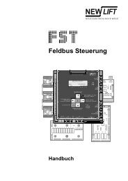
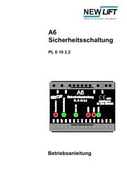
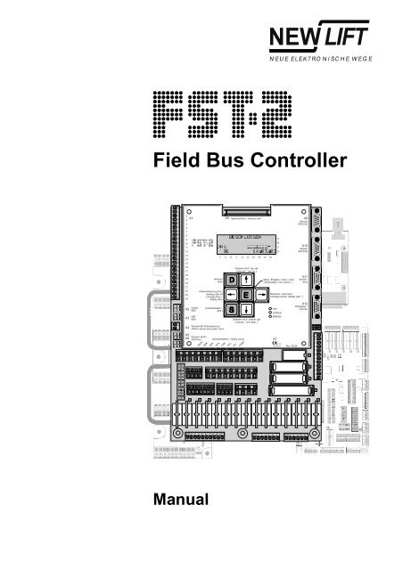
3 FST-2-<strong>Controller</strong> user interface<br />
Fig. 3.1 FST-2-<strong>Controller</strong> user interface<br />
3 FST-2-<strong>Controller</strong> user interface<br />
The user interface of the FST-2-<strong>Controller</strong> is located on the FST-2 main<br />
circuit board in the control cabinet of the lift system. The FST-2 user<br />
interface consists of front panel, LC-Display, keypad and LEDs.<br />
SAFETY CCT CLOSED<br />
FST-2_HB.EN12/05 9
3 FST-2-<strong>Controller</strong> user interface<br />
3.1 LC-Display and messages<br />
3.1 LC-Display and messages<br />
Main screen<br />
Line A<br />
SAFETY CCT CLOSED<br />
###@###<br />
>AX<<br />
13:06:56<br />
00<br />
Safety circuit messages<br />
in Line A<br />
The LC-Display consists of four lines A, B, C and D with 20 digits each.<br />
After switching on and during normal operation, the FST-2-<strong>Controller</strong><br />
displays the main screen.<br />
A Maximum active state of the safety circuit<br />
B Active state or error<br />
C Status of the lift system / diagnostic message<br />
D Data for current drive mode<br />
Line C has a special status. In normal mode (after switching on), it displays<br />
status messages (see “Status messages in line C” on page 13). When<br />
switching with key combination �+�+� it displays diagnostic<br />
messages, see “Diagnostic messages in line C” on page 14.<br />
Also see “Keypad functions” on page 32.<br />
Display Description<br />
CCT CLOSED The safety circuit is completely closed<br />
SAFETY<br />
(FST X14.1 & FST X14.2).<br />
MISSING The input “Safety circuit closed” has no power.<br />
SFTY-CLOSED<br />
Possible reasons:<br />
- Terminal FST X14.1 has no power (normally<br />
bridged with X14.2)<br />
- Relay K14 on the FST is faulty<br />
LOCK B OPEN The shaft door contact of door side B is<br />
DOOR<br />
interrupted (FST X14.2 and X14.3).<br />
LOCK A OPEN The shaft door contact of door side A is<br />
DOOR<br />
interrupted (FST X14.3 and X14.4).<br />
A OPEN The car door contact of door side A is<br />
DOOR<br />
interrupted (FST X14.4 and X14.5).<br />
B OPEN The car door contact of door side B is<br />
DOOR<br />
interrupted (FST X14.5 and X14.6).<br />
C OPEN The car door contact of door side C is<br />
DOOR<br />
interrupted (FST X14.6 and X14.7).<br />
DOOR OPEN A manual door contact is interrupted<br />
MANUAL<br />
(FST X14.6 and X14.7).<br />
END<br />
EMERGENCY<br />
SWITCH<br />
The top emergency end switch of an hydraulic<br />
lift is interrupted (FST X14.6 and X14.7).<br />
10 FST-2_HB.EN12/05
Line B<br />
State messages in line B<br />
3 FST-2-<strong>Controller</strong> user interface<br />
3.1 LC-Display and messages<br />
Display Description<br />
STOP An emergency switch in the shaft is interrupted<br />
EMERGENCY<br />
(terminals FST X14.7 and X14.8).<br />
STOP-CAR An emergency switch on the car is interrupted<br />
EMERGENCY<br />
(terminal FST X32.4).<br />
The messages DOOR C OPEN, MANUAL DOOR OPEN and EMERGENCY<br />
END SWITCH are triggered by the same safety circuit input of the FST-2<br />
(TC input: FST-2 X14.6) and exclude each other.<br />
Display Description<br />
LOW! The 24V supply of the FST-2 board (FST X1.1<br />
24V<br />
and X1.2) is below the permitted range of 24V -<br />
10%. Check power supply and wiring.<br />
CALLS OFF Landing control is blocked by a safety circuit<br />
LANDING<br />
interruption (interruption before terminal FST<br />
X32.4), line A EMERGENCY displays STOP,<br />
“EMERGENCY see STOP” on page 11.<br />
CONTROL OFF Landing control was switched off manually.<br />
LANDING<br />
Possible sources:<br />
� - key of the FST-2 keypad<br />
- Programmable input of an external RIO<br />
module<br />
- Input FST X1.14<br />
- Programmable input of the FST-2-<strong>Controller</strong><br />
- Key switch on car panel (FPM input X4.34)<br />
- Key switch on landing panel (ADM input<br />
X3.12 / X3.13)<br />
A fire input is active. Possible reasons:<br />
FIREMAN<br />
- Fire input on landing call module (ADM input<br />
X3.12 / X3.13)<br />
- Programmable input of the FST-2-<strong>Controller</strong><br />
- GST Group <strong>Controller</strong> (see GST <strong>Manual</strong>)<br />
TEST The manual end switch test is running, see test<br />
END-SWITCH<br />
menu.<br />
MON. TEST The manual test of the deceleration monitoring<br />
ES-SPEED<br />
function at the top and bottom limits is running,<br />
see test menu.<br />
The controller is in evacuation mode. Possible<br />
EVACUATION<br />
sources for the evacuation signal:<br />
- Programmable input of the FST-2-<strong>Controller</strong><br />
- Programmable input of the GST Group<br />
<strong>Controller</strong><br />
- LMS over PAM protocol adapter module<br />
FAX The controller is in fax mode (see Installation &<br />
SEND<br />
Commissioning – Fax modem).<br />
FST-2_HB.EN12/05 11
3 FST-2-<strong>Controller</strong> user interface<br />
3.1 LC-Display and messages<br />
Display Description<br />
OFF The controller was shut down. Possible<br />
LIFT<br />
sources:<br />
- Car light failure<br />
- Input “Car Light OFF”, FST X1.13<br />
- Programmable input/output of an external<br />
RIO module<br />
- Programmable input/output of the FST-2-<br />
<strong>Controller</strong><br />
- Externally by the GST Group <strong>Controller</strong> or the<br />
LMS <strong>Lift</strong> Monitoring System<br />
MODE Fireman mode is activated. Possible sources:<br />
FIREMAN<br />
- Key switch on car panel (FPM X4.4)<br />
- Programmable input/output of the FST-2-<br />
<strong>Controller</strong><br />
- The state was saved after a power failure and<br />
has been reconstructed. Fireman<br />
Function<br />
Reset must be used to reset this<br />
Mode<br />
state.<br />
- Key switch on landing panel (ADM input<br />
X3.12 / X3.13)<br />
- GST Group <strong>Controller</strong> (see GST <strong>Manual</strong>)<br />
TRANSFER<br />
FILE<br />
ACTIVE<br />
The controller is in remote data transmission<br />
mode to transfer files to a GST Group<br />
<strong>Controller</strong> or to a PC.<br />
The controller is in inspection mode (input FSM<br />
INSPECTION<br />
X22.2).<br />
Attention: Line A of the FST-2 display must<br />
EMERGENCY show STOP-CAR!<br />
- A calibration drive was started. The number of<br />
CALIBRATION<br />
remaining runs is displayed.<br />
The hinged car apron is open (due to a shaft<br />
APRON-OPEN!<br />
door interruption). Monitoring is done via a<br />
programmable input of the FST-2-<strong>Controller</strong>.<br />
DRIVE ACTIVE The controller performs a learn drive.<br />
LEARN<br />
DRIVE-START The controller performs a learn drive.<br />
LEARN<br />
DRIV-�OK! Learn drive completed successfully.<br />
LEARN<br />
DRIVE-ABORT The learn drive was cancelled due to a fault.<br />
LEARN<br />
The reason is entered in the error list.<br />
CURTAIN The safety curtain replacing the car door was<br />
SAFETY<br />
interrupted. The contact is in the safety circuit<br />
instead of the car door contacts (see System<br />
description – Safety curtain).<br />
.. A runtime monitoring error has occurred. There<br />
DRM<br />
are different types of runtime monitoring<br />
functions that can shut down the lift.<br />
MODE The controller is in installation mode.<br />
INSTALLATION<br />
The controller performs an orientation drive to<br />
ORIENTATION<br />
the top or bottom limit after switching on (only<br />
when using INK – incremental positioning). The<br />
orientation drive can take place automatically or<br />
when the first call is placed.<br />
12 FST-2_HB.EN12/05
Line C<br />
3 FST-2-<strong>Controller</strong> user interface<br />
3.1 LC-Display and messages<br />
Display Description<br />
DRIVE ACTIVE The controller sends the car to a programmed<br />
PARK<br />
parking floor.<br />
LANDING A priority landing drive was triggered. Possible<br />
PRIORITY<br />
sources:<br />
- Key switch on landing panel (ADM input<br />
X3.12 / X3.13)<br />
- Programmable input of the FST-2-<strong>Controller</strong><br />
- Programmable input of an external RIO<br />
module<br />
CAR A priority car drive was triggered. Possible<br />
PRIORITY<br />
sources:<br />
- Key switch on car panel (FPM input X4.37)<br />
- Automatically after a type Auto 2 priority<br />
landing drive.<br />
The controller is in auxiliary mode (input FST<br />
AUXILIARY<br />
X18.2).<br />
Attention: Line A of the FST-2 display must<br />
EMERGENCY show STOP!<br />
ACTIVE The hydraulic lift is sent to the lowest landing.<br />
HOMING<br />
ACTIVE The controller is in service mode, see test<br />
SERVICE<br />
menu.<br />
REQUIRED! One of the service counters has exceeded a set<br />
SERVICE<br />
limit.<br />
STOP The controller was stopped via the FST-2<br />
SYSTEM<br />
menu.<br />
The overload input on the FSM or on a<br />
OVERLOAD<br />
programmable input is active.<br />
ERROR - A user error has occurred. The number of the<br />
USER<br />
error is displayed.<br />
MODE The controller is in VIP mode. Possible sources<br />
VIP<br />
VIP mode:<br />
- LMS over PAM protocol adapter module<br />
- Programmable input of the FST-2-<strong>Controller</strong><br />
- FPM input X4.34 on car panel<br />
LOAD The full load input of the FSM is active.<br />
FULL<br />
Status messages in line C Line C is divided and displays one of the following status messages in the<br />
left and in the right part. For scrolling the status messages in the left part<br />
use the key combination �+�, for the right part use the key combination<br />
�+�.<br />
The door positions marked with A also apply to doors B and C.<br />
FST-2_HB.EN12/05 13
3 FST-2-<strong>Controller</strong> user interface<br />
3.1 LC-Display and messages<br />
<br />
>A<<br />
Status Display Description<br />
Car doors Door A completely open<br />
Door A closed<br />
Door A is opening<br />
<br />
Door A is closing<br />
->A>
3 FST-2-<strong>Controller</strong> user interface<br />
3.1 LC-Display and messages<br />
Display Description<br />
00000 Diagnosis of absolute value encoder<br />
LIK-Errs:00000<br />
function (see page 16), this display is<br />
irrelevant when using incremental<br />
positioning.<br />
Real-time display of increments counted by<br />
ENC:10000000[989680]<br />
the encoder on plug X2. The counted<br />
increments together with the covered<br />
distance can help when calculating the<br />
required Resolution.<br />
KO KU ZB Current state of the solenoid switches with<br />
Gray=43210<br />
incremental positioning, see page 16<br />
F1=00 F2=00 Current state of the FSM for door A, see<br />
Door-A:<br />
page 16<br />
F1=00 F2=00 Current state of the FSM for door B, see<br />
Door-B:<br />
page 16<br />
F1=00 F2=00 Current state of the FSM for door C, see<br />
Door-C:<br />
page 16<br />
VST=0000 Internal motor state (see page 19) and<br />
Motor=00<br />
states of the pre-selection contact outputs<br />
(see page 20)<br />
Real=00 Generated and actual position messages<br />
Pos:Virt=0b<br />
from the car, see page 20<br />
State of the safety circuit, see page 22<br />
SHK=SABCN<br />
Call=00 Internal NEW LIFT diagnostic message<br />
Mgr1:Drv=00<br />
B=00 C=00 Internal NEW LIFT diagnostic message<br />
Mgr2:A=02<br />
VT=V2 Next possible stop (NextPoss) that can<br />
NextPoss=ff<br />
be approached and the set speed (VT), see<br />
page 22<br />
EXIN1=EGALPUDR State of input EXIN1, see page 22<br />
Port<br />
EXIO2=76543210 State of input EXIN2, see page 23<br />
Port<br />
H8IN1=ZBSMVO State of input H8IN1, see page 23<br />
Port<br />
L=1 V=0 K=0 State of outputs on FSM X8 and X19, see<br />
FSM-X6:<br />
page 23<br />
00 00 00 00 Source of the special drive signals fireman,<br />
SRC:00<br />
fireman mode, landing control OFF, lift off<br />
and service mode, see page 24<br />
255% E0 F0 O0 State of the weight sensor, see page 25<br />
LWE:<br />
State of the project specific parts of the<br />
Proj.Status=........<br />
program (internal)<br />
m1 c0 f0 Mb005 State of the PC-Card slot, see page 26<br />
PC:s0<br />
In=005 Out=002 Incoming and outgoing data packets of the<br />
Pkt\s<br />
FST-<strong>Controller</strong> in [packets/sec]<br />
0000000 P=[00] State of the pawl device, see page 26<br />
ASV:<br />
msgs=00123 Number of message packets from the FSM<br />
FSM<br />
car control module to the FST-2-<strong>Controller</strong><br />
FST-2_HB.EN12/05 15
3 FST-2-<strong>Controller</strong> user interface<br />
3.1 LC-Display and messages<br />
Absolute value encoder<br />
function<br />
LIK-Errs:00000 00000<br />
State of incremental<br />
positioning<br />
Gray=43210 KO KU ZB<br />
The two numbers on the display show the number of encoder failures since the last<br />
activation of the system. The left number shows the different values resulting from<br />
double scanning, the right number shows the number of failed plausibility checks.<br />
Sporadic errors are compensated by the FST Software and can be tolerated. A<br />
continuous increase of one of these values indicates an encoder or cable failure.<br />
Left number:<br />
Right number:<br />
Display Description<br />
00000<br />
or constant value<br />
Communication between the FST-2-<strong>Controller</strong><br />
and the absolute value encoder is working<br />
correctly. Double scanning to suppress electric<br />
interference does not show any differences.<br />
constantly rising value Double scanning to suppress electric<br />
interference does show differences. There is<br />
electric interference on the connection cable<br />
between FST-2-<strong>Controller</strong> and encoder. Check<br />
connection cable and inform your NEW LIFT<br />
Hotline.<br />
Display Description<br />
The position values of the absolute value<br />
00000<br />
encoder are plausible (are within the regular<br />
shaft). There are no invalid jumps in the<br />
position value.<br />
The position values of the absolute value<br />
RANGE<br />
encoder are not plausible (are outside the<br />
regular shaft). Check direction of rotation of the<br />
encoder and commission the linear positioning<br />
function, see “Installation and Commissioning<br />
<strong>Manual</strong>”.<br />
There are invalid jumps in the position value.<br />
DELTA<br />
Absolute value encoder faulty.<br />
Code Description<br />
43210 State of Gray-coded pre-limit switches for high-speed lifts (optional)<br />
KO Correction switch top (KO) active<br />
KU Correction switch bottom (Ku) active<br />
ZB Zone switch B active<br />
16 FST-2_HB.EN12/05
States of the FSM car<br />
control module<br />
Door-A: F1=00 F2=00<br />
Fig. 3.2 Hexadecimal encoding of an 8-bit register<br />
3 FST-2-<strong>Controller</strong> user interface<br />
3.1 LC-Display and messages<br />
State bytes F1 and F2 describe the states of eight functions each in realtime<br />
(8 bits, hexadecimal code). Hexadecimal bytes are coded number by<br />
number. Each number has a decimal value according to the following table:<br />
Hexadecimal<br />
number<br />
Decimal<br />
value<br />
0<br />
0<br />
1<br />
1<br />
2<br />
2<br />
3<br />
3<br />
4<br />
4<br />
5<br />
5<br />
6<br />
6<br />
7<br />
7<br />
8<br />
8<br />
9<br />
9<br />
10<br />
a<br />
11<br />
b<br />
12<br />
c<br />
13<br />
d<br />
14<br />
e<br />
15<br />
f<br />
FST-2_HB.EN12/05 17<br />
digit<br />
digit
3 FST-2-<strong>Controller</strong> user interface<br />
3.1 LC-Display and messages<br />
Each number codes four functions (bits) of the F1/F2 table with its decimal<br />
value. The decimal value of the number corresponds to the sum of the<br />
values of the activated functions according to the following tables.<br />
F1 = Bit Number Value Setting Byte F1<br />
0<br />
1 active FSM car control module configured<br />
1 Number 1<br />
2 active Door locked<br />
2<br />
(right number)<br />
4 active Door reversing<br />
3 8 Door completely<br />
open<br />
Limit switch “door open”<br />
4<br />
1 Door completely Limit switch “door closed”<br />
Number 2<br />
closed<br />
5<br />
6<br />
(left number)<br />
2<br />
4<br />
active<br />
active<br />
Photocell interrupted<br />
Reversing contact<br />
7 8 active Minimum load input*<br />
F2 = Bit Number Value Setting Byte F2<br />
0<br />
1 on Car light sensor*<br />
1 Number 1<br />
2 active Inspection signal “fast”<br />
2<br />
(right number)<br />
4 active Inspection signal “down”<br />
3 8 active Inspection signal “up”<br />
4<br />
1 active Inspection signal “ON”<br />
5 Number 2<br />
2 active Door closing motor<br />
6<br />
(left number)<br />
4 active Door opening motor<br />
7 8 active Door ready for drive<br />
SAFETY CCT CLOSED<br />
F1=6c F2=21<br />
Door-A:<br />
13:06:<br />
00<br />
* Signal only relevant for door versions A and B.<br />
Example:<br />
State byte F1 = 6c and state byte F2 = 21<br />
This results in the following hexadecimal numbers:<br />
F1:<br />
Number 1 = “c” (decimal = 12)<br />
Number 2 = “6” (decimal = 6)<br />
F2:<br />
Number 1 = “1” (decimal = 1)<br />
Number 2 = “2” (decimal = 2)<br />
The decimal numbers are calculated from the following values:<br />
F1:<br />
Number 1 = 12 = 8 + 4<br />
18 FST-2_HB.EN12/05
Internal motor states<br />
Motor=00<br />
Internal states of the preselection<br />
relays<br />
Vst=0000<br />
Number 2 = 6 = 4 + 2<br />
F2:<br />
Number 1 = 1<br />
Number 2 = 2<br />
These values result in the following active bits:<br />
3 FST-2-<strong>Controller</strong> user interface<br />
3.1 LC-Display and messages<br />
F1:<br />
Number 1 = 8 + 4<br />
=>according to the table for F1 (Number 1) bits 2 and 3 are active<br />
=>the door is reversing and limit switch “open” has switched<br />
Number 2 = 4 + 2<br />
=>according to the table for F1 (Number 2) bits 5 and 6 are active<br />
=>the photocell is interrupted and the reversing contact has<br />
switched<br />
F2:<br />
Number 1 = 1<br />
=>according to the table for F2 (Number 1) bit 0 is active<br />
=>the door is reversing and limit switch “open” has switched<br />
Number 2 = 2<br />
=>according to the table for F2 (Number 2) bit 5 is active<br />
=>the car light sensor is active and the door motor is closing<br />
Internal motor states are coded according to the following table:<br />
Motor = Value motor state<br />
Motor ready<br />
00<br />
Motor starting<br />
01<br />
Motor running<br />
02<br />
03 Motor approaching stop position<br />
04 Motor braking<br />
05 Motor stopping<br />
digit<br />
digit<br />
digit 3<br />
digit<br />
4<br />
Fig. 3.3 Hexadecimal encoding of a 16-bit register<br />
8-11<br />
12-15<br />
FST-2_HB.EN12/05 19
3 FST-2-<strong>Controller</strong> user interface<br />
3.1 LC-Display and messages<br />
Position messages<br />
Pos: Virt=0b Real=00<br />
The four digit display provides a real-time description of the states of the<br />
pre-selection relays in hexadecimal code according to the following table.<br />
Hexadecimal values are coded number by number as described in<br />
page 17.<br />
VST = Bit Number Value Setting pre-selection relay<br />
0<br />
1 active Output FST K0<br />
1<br />
Number 1<br />
2 active Output FST K1<br />
2<br />
(right number)<br />
4 active Output FST K2<br />
3 8 active Output FST K3<br />
4<br />
1 active Output FST K4<br />
5 Number 2 2 active Output FST K5<br />
6 4 active Output FST K6<br />
7 8 active Output FST K7<br />
8<br />
1 active Output FST K8<br />
9 Number 3 2 active Output FST K9<br />
10 4 active Output FST K10<br />
11 8 active Output FST K11<br />
12<br />
1 active Output FST K12<br />
13 Number 4 2 active Zone signal B<br />
14<br />
15<br />
(left number)<br />
4<br />
8<br />
active<br />
active<br />
Safety circuit bypass FST K20<br />
Enable zone switching FST K21<br />
The generated (virtual) and actual (real) position messages of the car<br />
describe the states of eight switches each (8 bits, hexadecimal code) in<br />
real-time according to the following table. Hexadecimal values are coded<br />
number by number as described in page 17.<br />
Virt = Bit Number Value Setting virtual position<br />
0<br />
1 active Level (A and B)<br />
1 Number 1 2 active Level (A and B) with motor stopped<br />
2<br />
3<br />
(right number)<br />
4<br />
8<br />
active<br />
active<br />
Approach area<br />
Zone switch B (FST K23)<br />
4<br />
1 active Relevelling “up”<br />
5 Number 2 2 active Relevelling “down”<br />
6<br />
(left number)<br />
4 active Enable zone switching (FST K21)<br />
7 8 Not assigned<br />
20 FST-2_HB.EN12/05
3 FST-2-<strong>Controller</strong> user interface<br />
3.1 LC-Display and messages<br />
Real = Bit Number Value Setting real position<br />
0<br />
1 active Zone message (FST K22 & K23 active at the same time)<br />
1 Number 1 2 active Correction switch top KO (INK)<br />
2<br />
(right number)<br />
4 active Correction switch bottom KU (INK)<br />
3 8 active Level bottom LB (INK, optional)<br />
4<br />
1 active Level top LT (INK, optional)<br />
5 Number 2 2 active Brake monitoring (FST X1.19 & X1.20)<br />
6<br />
(left number)<br />
4 active Motor monitoring (FST X1.22)<br />
7 8 active Zone switch B (with INK)<br />
FST-2_HB.EN12/05 21
3 FST-2-<strong>Controller</strong> user interface<br />
3.1 LC-Display and messages<br />
States of the safety circuit<br />
Shk=SABCN<br />
Next possible stop<br />
NextPoss=ff<br />
Current set speed<br />
Vt=V2<br />
Input EXIN1<br />
Port EXIN1=EGALPDUR<br />
The state of the safety circuit is coded according to the following table:<br />
Code Description<br />
Locking device open<br />
S<br />
Door A open<br />
A<br />
Door B open<br />
B<br />
Car door C (revolving door, emergency end switch top) open<br />
C<br />
Emergency stop<br />
N<br />
The next possible stop that can be approached by the car is coded with<br />
hexadecimal values according to the following table:<br />
Code NextPoss=<br />
Description<br />
All floors possible (car is at rest)<br />
ff<br />
No further floor possible (when decelerating)<br />
fe<br />
Next possible stop = code (hexadecimal)<br />
00..3f<br />
The current set speed of the motor is coded according to the following<br />
table:<br />
Code Vt=<br />
Description<br />
Drive speed 1 .. 8 (for standard drives)<br />
V1..V8<br />
ve Approach speed<br />
Fast inspection speed<br />
Vi<br />
Relevelling speed<br />
Vn<br />
Input EXIN1 displays the states of the controller inputs according to the<br />
following table:<br />
R<br />
U<br />
D<br />
Bit Terminal Setting Description<br />
FST X18.2 active Auxiliary control ON<br />
FST X18.3 active Auxiliary control UP<br />
FST X18.4 active Auxiliary control DOWN<br />
P<br />
L FST X1.14 active Car light OFF<br />
A<br />
G<br />
E<br />
FST X1.15 active Landing control OFF<br />
active GST found<br />
active Alarm<br />
22 FST-2_HB.EN12/05
Input EXIO2<br />
Port EXIO2=76543210<br />
Input H8IN1<br />
Port H8IN1=ZBSMUO<br />
FSM-X6<br />
FSM-X6: L=1 V=0 K=0<br />
3 FST-2-<strong>Controller</strong> user interface<br />
3.1 LC-Display and messages<br />
Input/output EXIO2 displays the states of the programmable inputs and<br />
outputs according to the following table:<br />
Bit Terminal Setting Description<br />
0<br />
1<br />
2<br />
3<br />
4<br />
5<br />
6<br />
7<br />
FST X1.4 active Programmable input/output 0<br />
FST X1.5 active Programmable input/output 1<br />
FST X1.6 active Programmable input/output 2<br />
FST X1.7 active Programmable input/output 3<br />
FST X1.8 active Programmable input/output 4<br />
FST X1.9 active Programmable input/output 5<br />
FST X1.10 active Programmable input/output 6<br />
FST X1.11 active Programmable input/output 7<br />
Input H8IN1 displays the inputs of the drive processor according to the<br />
following table:<br />
O<br />
U<br />
M<br />
S<br />
B<br />
Z<br />
Bit Terminal Setting Description<br />
0 Not assigned<br />
1 Not assigned<br />
FSM X13.1 active Correction switch top “KO”<br />
FSM X13.3 active Correction switch bottom “KU”<br />
FST X1.22 active Motor monitoring<br />
FST X1.23 active Standstill monitoring<br />
FST X1.19/20 active Brake monitoring<br />
FST X13.9 active Zone message<br />
The FSM-X6 display shows the states of the following outputs of the car<br />
control module:<br />
L=<br />
0<br />
1<br />
Code Terminal Setting car light<br />
FSM X19.1 active Car light OFF<br />
FSM X19.1 not active Car light ON<br />
V=<br />
0<br />
1<br />
Code Terminal Setting car ventilator<br />
FSM X19.4 not active Car ventilator OFF<br />
FSM X19.4 active Car ventilator ON<br />
FST-2_HB.EN12/05 23
3 FST-2-<strong>Controller</strong> user interface<br />
3.1 LC-Display and messages<br />
Source of special drive<br />
signals<br />
SRC:00 00 00 00<br />
Code Terminal Setting K= door lock solenoid<br />
0 FSM X8.3 not active Door lock solenoid released<br />
1 FSM X8.3 active Door lock solenoid activated<br />
The special drive signals fire, fireman mode, landing control OFF, lift off<br />
and service mode can be activated by different signal sources (e.g. ADM,<br />
FPM etc.). The sources are displayed as follows:<br />
Fig. 3.4 Signals sources of SRC display<br />
Coding of the source display:<br />
Code Code for fire signal<br />
01 ADM landing call module<br />
02 Programmable input/output of the FST-<strong>Controller</strong><br />
04 GST Group <strong>Controller</strong><br />
Code Code for fireman mode signal<br />
01 FPM car panel module, X4.4<br />
02 Programmable input/output of the FST-<strong>Controller</strong><br />
The state was saved after a power failure and has been<br />
04<br />
reconstructed.<br />
ADM landing call module<br />
08<br />
10 GST Group <strong>Controller</strong><br />
Source of “Service Mode”<br />
Source of “<strong>Lift</strong> Off”<br />
Source of “Landing Control Off”<br />
Source of “Fireman Mode”<br />
Source of “Fire Mode”<br />
24 FST-2_HB.EN12/05
Weight sensor<br />
LWE: 255% E0 F0 O0<br />
3 FST-2-<strong>Controller</strong> user interface<br />
3.1 LC-Display and messages<br />
Code Code for landing control OFF signal<br />
� key of the FST keypad<br />
01<br />
Programmable input/output of an external RIO module<br />
02<br />
04 Input “Landing control OFF”, FST X1.15<br />
08 Programmable input/output of the FST-<strong>Controller</strong><br />
FPM car panel module, X4.34<br />
10<br />
ADM landing call module<br />
20<br />
40 Push button mode (see “Special call mode” on page 135)<br />
Code Source for lift off signal<br />
<strong>Lift</strong> off after a car light failure<br />
01<br />
02 Input “Car light OFF”, FST X1.14<br />
Programmable input/output of an external CUS module or ADM<br />
04<br />
Programmable input/output of the FST-<strong>Controller</strong> or external RIO<br />
08<br />
module<br />
External by the GST Group <strong>Controller</strong> or the LMS lift monitoring<br />
10<br />
system<br />
Code Source for service mode signal<br />
External via LMS lift monitoring system<br />
01<br />
02 TEST MENU – Service Mode ON<br />
04 Programmable input/output of the FST-<strong>Controller</strong><br />
The state of the weight sensor inputs and the loading level of the car when<br />
using analogue weight sensors is displayed as follows:<br />
Fig. 3.5 State of the weight sensor<br />
State of Input “Overload”, FSM X5.4<br />
State of Input “Full-Load”, FSM X5.3<br />
State of Input “Minimum Load”, FSM X5.2<br />
Loading Level of the Car in %<br />
(when using analogue weight sensor)<br />
“0”: Input not active<br />
“1”: Input active<br />
FST-2_HB.EN12/05 25
3 FST-2-<strong>Controller</strong> user interface<br />
3.1 LC-Display and messages<br />
PC-Card<br />
PC:s0 m1 c0 f0 Mb005<br />
State of pawl<br />
device<br />
ASV: 0000000 P=[00]<br />
Code Description<br />
No PC-Card inserted<br />
s0<br />
s1 PC-Card inserted – card type not detected<br />
PC-Card inserted – card type detected / card OK<br />
s2<br />
PC-Card inserted – card type not detected / error<br />
s3<br />
m0 PC-Card memory type unknown<br />
m1 Card type: static RAM<br />
m2 Card type: flash memory<br />
CIS memory: no CIS found<br />
c0<br />
CIS status: CIS OK<br />
c1<br />
f0 Flash type: PC-Card unknown / unusable<br />
Flash type: AMD A28F040 – 512kB memory module<br />
f1<br />
Flash type: INTEL I28f016 – 2MB memory module<br />
f2<br />
Size of memory storage in 0.1 MB steps<br />
Mb<br />
The state of the pawl device is coded as follows:<br />
ASV: .......<br />
0<br />
Bit Setting Description<br />
(right)<br />
active Pump for bolt control ON<br />
1 active Valve “extend bolt” activated<br />
2 active Valve “retract bolt” activated<br />
3 active End switch “bolt extended” active<br />
4 active End switch “bolt retracted” active<br />
5<br />
6 active Input “re-pumping” active<br />
(left)<br />
active Input “car bottomed” active<br />
P=[..]<br />
0 Standstill<br />
1<br />
2<br />
3<br />
4<br />
5<br />
6<br />
7<br />
0<br />
1<br />
2<br />
Digit<br />
1 (right)<br />
Code Description<br />
1 (right) Main contactors ON, waiting for star-delta start-up<br />
1 (right) <strong>Lift</strong> car (approx. 30mm / 1 3/16")<br />
1 (right) Motor run-on active<br />
1 (right) Waiting for bolts to extend or retract<br />
1 (right) Bolts extended or retracted completely<br />
1 (right) Waiting for input “car bottomed”<br />
1 (right) Delay after stop<br />
2 (left) No bolt movement<br />
2 (left) Bolts are retracting<br />
2 (left) Bolts are extending<br />
26 FST-2_HB.EN12/05
Line D<br />
Drive mode messages<br />
in line D<br />
3 FST-2-<strong>Controller</strong> user interface<br />
3.1 LC-Display and messages<br />
P=[..]<br />
3<br />
4<br />
Digit Code Description<br />
2 (left) Re-pumping active<br />
2 (left) Error in bolt control<br />
T<br />
Column Display Description<br />
1 Auto test drive active<br />
S<br />
s<br />
{<br />
}<br />
10<br />
[13]<br />
[13<br />
13]<br />
X13<br />
13X<br />
G<br />
g<br />
R<br />
F<br />
10:44:12<br />
2<br />
No serial connection to the frequency converter<br />
(FST-2 X11)<br />
Data transmission to the frequency converter<br />
via serial connection is faulty (FST-2 X11)<br />
Direction display UP<br />
3-4 Current floor of car<br />
5-8<br />
Direction display DOWN<br />
Car and landing call to target floor<br />
9<br />
Car call to target floor<br />
Landing call to target floor<br />
Car control blocked<br />
Landing control blocked<br />
Not assigned<br />
10 FST-2 is integrated in a GST Group <strong>Controller</strong><br />
11<br />
FST-2 is integrated in a GST Group <strong>Controller</strong><br />
but communication with the GST is faulty<br />
Flashes when recording data on the PC card<br />
12 Not assigned<br />
13-20<br />
Card is cleared<br />
Current time of the FST-2<br />
FST-2_HB.EN12/05 27
3 FST-2-<strong>Controller</strong> user interface<br />
3.1 LC-Display and messages<br />
Information texts<br />
When triggering actions in the FST menu, information texts may be<br />
displayed. They contain information about the results of the action.<br />
Display Description<br />
EMERGENCY OPERATION<br />
*!!<br />
!!*<br />
The controller is in emergency operation mode. Drives are not possible.<br />
Emergency operation is activated by pressing the � key while switching the<br />
system on.<br />
STUCK :... The landing call from the specified floor and door side is permanently activated<br />
ADM<br />
(is stuck).<br />
unconfigured! A landing call module connected to the shaft bus is not configured. Inform your<br />
ADM<br />
NEW LIFT Hotline!<br />
Reject CODE: A landing call was placed but not carried out. The code displays the reason for<br />
ADR<br />
the suppression, see “ADR Reject codes:” on page 30.<br />
INHIBIT ON! Mutual start-up blocking via the LMS bus is active. Starting will be delayed until<br />
DRIVE<br />
the networked systems have completed their acceleration phases.<br />
wait! The triggered action has not been completed. Please wait!<br />
Please<br />
SENT OK! A status fax was sent successfully via the modem interface.<br />
FAX\SMS<br />
-> GST! A fax/sms (text message) is sent to the group controller where it will be sent via<br />
FAX\SMS<br />
the FAX-modem.<br />
NOT SENT! Transmission of a status fax via the modem interface was aborted. Check<br />
FAX\SMS<br />
modem and telephone connection. MAIN MENU - Configuration<br />
See<br />
Modem\Fax\LMS<br />
-<br />
NOT FOUND! The inserted PC-Card does not contain the file(s) required for the triggered<br />
FILE<br />
action.<br />
software update The software of the FST-2 is updated with a PC-Card. The progress in [%] is<br />
FST<br />
displayed in line C.<br />
UPDATE COMPLETE! The software update of the GST Group <strong>Controller</strong> is complete.<br />
GST<br />
CAR ACTIVE... Soft priority car is waiting for standstill after the pending car call. See MAIN<br />
PRIO<br />
- Configuration - Prio-landing\car.<br />
MENUE<br />
Reject CODE: A car call was placed but not carried out. The code displays the reason for the<br />
IDR<br />
suppression, see “IDR Reject codes:” on page 30.<br />
abort! The calibration drive was aborted. Check function of connected drive speeds.<br />
Calibration<br />
Locate reason for drive abortion in the error list.<br />
SIGNAL The car is on the top floor and the correction top signal is missing (only when<br />
NO<br />
using INK – incremental positioning). Check function of KO switch. Check<br />
settings MAIN MENUE - Positioning - Increm.Positng. -<br />
in<br />
KO\KU-level.<br />
SIGNAL The car is on the bottom floor and the correction bottom signal is missing (only<br />
NO<br />
when using INK – incremental positioning). Check function of KU switch. Check<br />
settings MAIN MENUE - Positioning - Increm.Positng. -<br />
in<br />
KO\KU-level.<br />
TRANSFER ERR! An error has occurred during copying of the controller configuration.<br />
CONFIG<br />
CONFIG TRANSFER OK! <strong>Controller</strong> configuration copied successfully.<br />
CONFIG[D] CORRUPT! A parameter of the drive configuration is not plausible. Change a parameter in<br />
MAIN MENU - Drive and undo the change again. The information text<br />
disappears after saving the settings.<br />
28 FST-2_HB.EN12/05
Display Description<br />
3 FST-2-<strong>Controller</strong> user interface<br />
3.1 LC-Display and messages<br />
CORRUPT! A parameter of the system configuration is not plausible. Change a parameter<br />
CONFIG[S]<br />
MAIN MENU - Configuration in and undo the change again. The<br />
information text disappears after saving the settings.<br />
DRIVE FAILURE! The started learn drive was not successful. Check function of signals zone B,<br />
LEARN<br />
correction bottom and correction top.<br />
START FAILURE! The started learn drive was aborted due to the car not moving even with pre-<br />
LEARN<br />
selection active.<br />
STARTED! A DRM-test was triggered.<br />
DRM-TEST<br />
DRM-TEST FINISHED! The DRM-test was completed successfully.<br />
NUISANCE DETECT! The car nuisance protection function has triggered. See MAIN MENU -<br />
CAR<br />
- Anti Nuisance.<br />
Configuration<br />
IN THE ZONE! The started learn drive cannot be completed because the car is not in the door<br />
NOT<br />
zone. Check function of zone B signal and settings MAIN MENU -<br />
in<br />
- Increm.Positng. - ZoneB-Level.<br />
Positioning<br />
IN FLOOR-0! The started learn drive cannot be completed because the car is not on the<br />
NOT<br />
lowest floor (check correction switch bottom, KU).<br />
FROM END FLOOR! The car is at an end floor. The triggered end switch test cannot be started from<br />
NOT<br />
this floor.<br />
An alarm button was operated or is faulty (see wiring diagram).<br />
CALL<br />
EMERGENCY<br />
ACTIVATED!<br />
FROM END FLOOR! The triggered drive test can only be started from an end floor.<br />
ONLY<br />
REMOVED! The inserted PC-Card was removed from slot X8.<br />
PC-CARD<br />
FLASH TYPE?? The memory type of the inserted PC-Card is unknown. The PC-Card cannot be<br />
PC-CARD<br />
used.<br />
EMPTY! The inserted PC-Card was cleared successfully.<br />
PC-CARD<br />
LOW BATTERY! The battery voltage of the inserted PC-Card is too low. Change battery!<br />
PC-CARD<br />
OK! The inserted PC-Card has been recognized by the controller and can be used.<br />
PC-CARD<br />
TYPE????! The inserted PC-Card is not recognized by the controller and cannot be used.<br />
PC-CARD<br />
Update File Updating the software. The inserted PC-Card is checked for update files.<br />
Checking<br />
RECORDING RESTART! An already started recording was restarted.<br />
RECORDING STOPPED! Recording is stopped.<br />
RECORDING NEWSTART! A new recording is started.<br />
LEVEL! The supervisor level is accessed with a master password. It enables setting<br />
SUPERVISOR<br />
hidden parameters.<br />
FILE FOUND The file required for the software update was found on the PC-Card. The<br />
UPDATE<br />
software is updated.<br />
COMPLETE! The software update of the LON module was completed successfully.<br />
UPDATE<br />
TO RESET... Automatic RESET after changing basic parameters (e.g. Drive type). This<br />
WAITING<br />
may take a few seconds.<br />
SLIPPAGE!! During the last drive of the learn drive, hysteresis of the connected solenoid<br />
EXCESSIVE<br />
switches KO, KU and zone B was detected (only when using INK – incremental<br />
positioning). If a value greater than 10 mm is measured this message is<br />
displayed. Hysteresis will be limited to 10 mm automatically.<br />
Nudging (forced closure) of the car door is activated. Photocell and reversing<br />
DOOR-NUDGING!<br />
contacts are ignored. MAIN MENU - Doors - Doors<br />
See<br />
- Photocell and MAIN MENU - Doors - Doors<br />
Selective<br />
- Nudge Time.<br />
Selective<br />
FST-2_HB.EN12/05 29
3 FST-2-<strong>Controller</strong> user interface<br />
3.1 LC-Display and messages<br />
ADR Reject codes:<br />
IDR Reject codes:<br />
Code Description<br />
5 Call from an unconfigured ADM<br />
6 Landing calls are currently blocked<br />
20 The call is from an unregistered door side or floor (see call menu)<br />
21 The call is currently blocked (programmable input)<br />
22 The call is currently blocked (LMS remote monitoring)<br />
24 The call is stuck<br />
Control is a push button control (not collective) and the lift is<br />
25<br />
currently occupied<br />
The call is currently blocked (MA35 control)<br />
26<br />
Code Description<br />
Anti nuisance (car is empty)<br />
10<br />
11 Anti nuisance (maximum number of car calls exceeded)<br />
20 The call is from an unregistered door side or floor (see call menu)<br />
21 The call is currently blocked (programmable input)<br />
The call is currently blocked (LMS remote monitoring)<br />
22<br />
The call is stuck<br />
24<br />
The call is currently blocked (Attika control)<br />
25<br />
Control is a push button control (not collective) and the lift is<br />
26<br />
currently occupied<br />
The call is currently blocked (MA35 control)<br />
27<br />
28 The call is currently blocked (ramp control)<br />
30 FST-2_HB.EN12/05
Information page<br />
FST-2 Information -<br />
-<br />
Ver.:14-16<br />
HW<br />
VER.:V1.100-0350<br />
SW<br />
:18\05\2005<br />
Messages in<br />
lines B, C and D<br />
3 FST-2-<strong>Controller</strong> user interface<br />
3.1 LC-Display and messages<br />
The information page contains important information on the individual<br />
configuration of your FST-2-<strong>Controller</strong>.<br />
It can be accessed with key combination �+� and closed with �. The<br />
�/� keys are used to navigate through the information page.<br />
A Information page<br />
B Hardware version 12-16 of FST-2<br />
C Software version V1.100-0350 of FST-2<br />
D Release date of the software version<br />
Display Description<br />
VER.:14-16 Hardware version of the FST-2 board<br />
HW<br />
Software version with release date<br />
Ver.:V1.100-0350<br />
SW<br />
:18\05\2005<br />
Ver:0104 Software version of the operating system<br />
Boot<br />
Ver: FSM00125 Software version of the FSM car control<br />
FSM<br />
module. If no software version is displayed<br />
here there is no bus connection to the FSM.<br />
Ver: FPM00128 Software version of the FPM car panel<br />
FPM<br />
module. If no software version is displayed<br />
here there is no bus connection to the FPM.<br />
Internal identification of the controller. The<br />
<strong>Lift</strong>ID:A<br />
ID displayed here must correspond to the<br />
jumper settings of FSM and FPM.<br />
Neuron-ID..<br />
00 22 C1 fb 00<br />
01<br />
SystemID..<br />
bench<br />
Test<br />
number..<br />
Factory<br />
RC9900234<br />
Unique ID for identification of the FST-2-<br />
<strong>Controller</strong><br />
System location or name<br />
Order number of the individual lift system<br />
Start:12\07\05 08:23 Date and time of activation<br />
:12\07\05 10:23 Date and time of last calibration drive<br />
CAL<br />
14:03 Start date and time of the current statistics<br />
STATS:27\07\05<br />
recording<br />
12:05 Date and time of the last change of a<br />
Cfg:12\07\05<br />
parameter in the FST menu<br />
12:06 Date and time of the current backup copy in<br />
CfgBk:12\07\05<br />
the internal buffer<br />
12:07 Date and time of the last reset of the error<br />
Err:12\07\05<br />
list<br />
Current security level of the FST-2<br />
Sec.Level:1<br />
FST-2_HB.EN12/05 31
3 FST-2-<strong>Controller</strong> user interface<br />
3.2 Keypad functions<br />
3.2 Keypad functions<br />
Frequency converter with DCP interface<br />
When switching on<br />
The FST-2-<strong>Controller</strong> is operated using seven keys. The keys have<br />
different functions in the different displays.<br />
�<br />
�<br />
Operation and parametrising of frequency converters with<br />
DCP interface can be done from the FST-2 menu (FST X11<br />
connected). The display of the frequency converter can be<br />
simulated on the FST-2 display by pressing the � key once.<br />
The FST-2 keys provide access to the functions of the<br />
frequency converter. The FST-2 display returns to standard<br />
mode by pressing the � key again.<br />
Pressing and holding key � during the switch-on sequence of<br />
the FST-2 starts emergency operation. In emergency<br />
operation no drives are possible. Emergency operation is<br />
required if the FST-2 cannot be switched on in normal mode<br />
due to a malfunction. The complete FST menu and the PC-<br />
Card functions are active in emergency mode!<br />
32 FST-2_HB.EN12/05
Main screen<br />
SAFETY CCT CLOSED<br />
###@###<br />
>A<<br />
13:06:56<br />
00<br />
Main menu and test menu<br />
MENU<br />
MAIN<br />
><br />
Drive<br />
Configuration<br />
>Positioning<br />
><br />
Clock setting<br />
13:45:01<br />
�<br />
�<br />
�<br />
�<br />
�<br />
�<br />
�+�<br />
�+�<br />
�+�<br />
�+�<br />
�+�<br />
�+�+�<br />
Set car call to top floor<br />
Set car call to bottom floor<br />
3 FST-2-<strong>Controller</strong> user interface<br />
3.2 Keypad functions<br />
Switch landing control on and off (switch function)<br />
Open test menu<br />
Open main menu<br />
Press before switching on and hold until the start-up sequence<br />
of the FST-2 is completed: Emergency operation is activated,<br />
see “*!! EMERGENCY OPERATION !!*” on page 28.<br />
Set car call to next floor up<br />
Set car call to next floor down<br />
Scroll through the right status messages in line C<br />
Scroll through the left status messages in line C<br />
Display information page<br />
Toggle diagnostic messages in line C on and off<br />
�+�+�+� <strong>Controller</strong> RESET<br />
�<br />
�<br />
�<br />
�<br />
�<br />
�<br />
�<br />
�<br />
�<br />
�<br />
Move cursor up<br />
Move cursor down<br />
Exit submenu<br />
Change menu level<br />
Select submenu / menu item<br />
Increase value<br />
Decrease value<br />
Move cursor left<br />
Move cursor right<br />
Confirm settings<br />
FST-2_HB.EN12/05 33
3 FST-2-<strong>Controller</strong> user interface<br />
3.3 LEDs<br />
Error list<br />
[00037\00040]<br />
ERROR<br />
10:18:26 [012]<br />
28.09<br />
close failed<br />
Door<br />
03 V00 R01 I00<br />
FLOOR:<br />
Information page<br />
FST-2 Information -<br />
-<br />
Ver.:12-16<br />
HW<br />
VER.:V1.100-0026<br />
SW<br />
:18\05\1999<br />
3.3 LEDs<br />
�<br />
�<br />
�+�<br />
�+�<br />
�<br />
�<br />
�<br />
Switch to 2nd to 8th information byte in line D<br />
Switch to initial display in line D<br />
To previous error message<br />
To next error message<br />
Scroll one line up<br />
Scroll one line down<br />
Back to main screen<br />
Three LEDs on the front panel of the FST-2-<strong>Controller</strong> display the device<br />
status.<br />
�<br />
LED Colou<br />
r<br />
State Reason Action<br />
RUN green on The power supply is on<br />
The hardware of the FST-2-<br />
<strong>Controller</strong> is working correctly<br />
off No power Check the 24V power supply of the FST-<br />
2-<strong>Controller</strong><br />
The hardware of the FST-2-<br />
<strong>Controller</strong> is faulty<br />
Inform your NEW LIFT Hotline!<br />
STATUS green on The drive processor is working<br />
correctly<br />
flashing Landing control OFF switches landing control back on<br />
off Fault in drive processor Inform your NEW LIFT Hotline!<br />
ERROR red on Drive not possible Line B shows the reason of the error. A<br />
drive is only possible after the error has<br />
been corrected.<br />
flashing One or more errors were added to<br />
the error list<br />
off There is no error or event<br />
The ERROR LED is off after the error list<br />
has been called up.<br />
34 FST-2_HB.EN12/05
4 Technical data<br />
4 Technical data<br />
The FST-2 <strong>Lift</strong> <strong>Controller</strong> from NEW LIFT is the result of many years of<br />
product experience in the area of lift system controller design and close cooperation<br />
with various component manufacturers, technical regulatory<br />
authorities and of course our customers.<br />
The lift control system consists of the FST-2 main circuit board with user<br />
interface, electronic assemblies and cables. The individual components of<br />
the FST-2 <strong>Lift</strong> <strong>Controller</strong> are described, and dimensions, jumpers, LEDs,<br />
terminals and plugs are explained. All FST-2 components described in this<br />
manual are shown in the “FST-2-<strong>Controller</strong> component overview (bus<br />
plan)” on page 36.<br />
FST-2_HB.EN12/05 35
4 Technical data<br />
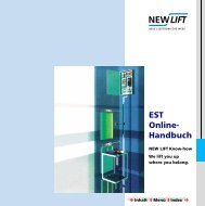
4.1 Component overview – bus plan<br />
4.1 Component overview – bus plan<br />
green<br />
( 10)<br />
blue<br />
( 7)<br />
blue<br />
( 7)<br />
blue<br />
( 7)<br />
blue<br />
( 7)<br />
blue<br />
( 7)<br />
blue<br />
( 7)<br />
FST-A<br />
A B X 4 Opt.<br />
ADM-S<br />
ADM-S<br />
ADM-S<br />
ADM-S<br />
ADM-S<br />
ADM-S<br />
ADM-S<br />
Fig. 4.1 FST-2-<strong>Controller</strong> component overview (bus plan)<br />
NEW LIFT provides an overview of the individual components known as<br />
“bus plan” that is supplied with the circuit documentation of each lift system.<br />
For each electronic assembly, installation site, associated bus and the<br />
respective LON bus cable lengths are specified in the bus plan. Each<br />
electronic assembly is clearly labelled on the circuit board. Using this<br />
labelling, the individual components can be identified on the bus plan.<br />
S/<br />
0/<br />
A/<br />
6/<br />
A<br />
S/<br />
0/<br />
A/<br />
5/<br />
A<br />
S/<br />
0/<br />
A/<br />
4/<br />
A<br />
S/<br />
0/<br />
A/<br />
3/<br />
A<br />
S/<br />
0/<br />
A/<br />
2/<br />
A<br />
S/<br />
0/<br />
A/<br />
1/<br />
A<br />
S/<br />
0/<br />
A/<br />
0/<br />
A<br />
36 FST-2_HB.EN12/05<br />
0,<br />
5<br />
trailing cable 32,5 m<br />
FSM<br />
FPM<br />
IK<br />
IK<br />
Example:<br />
type/bus/door/floor/FST<br />
S / 0 / A / 0 / A<br />
Legend<br />
:<br />
IK = Inspection Cabinet<br />
FK = car / COP<br />
Hose with colour code<br />
on the bus cable ends:<br />
0,<br />
5m<br />
= sw<br />
= schwarz=<br />
black<br />
1,<br />
0m<br />
= rt<br />
= rot<br />
= red<br />
3,<br />
0m<br />
= ws<br />
= weiss<br />
= white<br />
5,<br />
0m<br />
= ge<br />
= gelb<br />
= yellow<br />
7,<br />
0m<br />
= bl<br />
= blau<br />
= blue<br />
10,<br />
0m<br />
= gn<br />
= grün<br />
= green<br />
15,<br />
0m<br />
= sw<br />
= schwarz=<br />
black<br />
20,<br />
0m<br />
= rt<br />
= rot<br />
= red
4.2 FST-2-<strong>Controller</strong><br />
4 Technical data<br />
4.2 FST-2-<strong>Controller</strong><br />
All common types of cable and hydraulic lifts can be operated using the<br />
FST-2-<strong>Controller</strong>. The pre-assembled FST-2-<strong>Controller</strong> can easily be<br />
adapted to any individual lift system on site using the FST menu. <strong>New</strong><br />
software versions can be installed at any time via the PC-Card slot without<br />
changing system-specific settings.<br />
Components and features of the FST-2-<strong>Controller</strong>:<br />
Components:<br />
- FST-2 main circuit board with separate processors for call processing,<br />
drive control and bus management<br />
- Integrated repeater for electrical isolation of shaft bus and car bus<br />
- RS-585 / RS-422 / RS-232 controller interfaces for communication with<br />
drive regulators<br />
- Encoder interface for connecting common absolute value and<br />
incremental encoders<br />
- Flash memory and battery-buffered RAM for error memory with up to<br />
100 entries<br />
- PC-Card / PCMCIA slot for using memory cards<br />
- RS-232 modem interface for remote data transmission, FAX and PAM<br />
functions<br />
- RS-232 PC interface (laptop on site)<br />
- LC-Display with 4 × 20 characters (ASCII character set)<br />
- Keypad for intuitive navigation in main menu and test menu<br />
- 8 programmable inputs and outputs on the FST-2 main circuit board<br />
- 72 programmable inputs and outputs on additional RIO Modules<br />
An overview of the features and functions of FST-2-<strong>Controller</strong> can be found<br />
in the description of the controller.<br />
FST-2_HB.EN12/05 37
4 Technical data<br />
4.2 FST-2-<strong>Controller</strong><br />
Technical data Description Value Unit<br />
Supply voltage 24 ±10% V DC<br />
Power consumption 300 mA<br />
Length × width × height<br />
Temperature range<br />
200 × 310 × 50 (7 7/<br />
8 × 12 3/16 × 2)<br />
mm (inch)<br />
Storage / transport -20 - +70 (-4 - +158) °C (°F)<br />
Operation<br />
Relative humidity<br />
±0 - +60 (32 - 140) °C (°F)<br />
Storage / transport 5 - 95 %<br />
Operation 15 - 85 %<br />
38 FST-2_HB.EN12/05
310<br />
85<br />
120 85<br />
27,5<br />
X1 .2 .3 .4 .5 .6 .7 .8 .9 .10 .11 .12 .13 .14.15 .16 .17 .18.19 .20.21 .22 .23.2 4<br />
X4 .2<br />
Fig. 4.2 FST-2-<strong>Controller</strong><br />
77<br />
X20.2 .3 .4 .5 .6 .7 .8 .9 .10 X21.2 .3 .4 .5 .6 .7 X22.2 .3 .4 .5 .6<br />
4 Technical data<br />
4.2 FST-2-<strong>Controller</strong><br />
FST-2_HB.EN12/05 39<br />
200<br />
145<br />
10 85 90<br />
10<br />
68<br />
27,5<br />
X13.2 .3 .4 .5 .6 .7 .8 .9 .10 .11 .12<br />
5<br />
10
4 Technical data<br />
4.2 FST-2-<strong>Controller</strong><br />
Jumpers<br />
Unused jumpers<br />
Not plugged:<br />
J1 (service jumper)<br />
Jumper J90 Shielding X9<br />
Fig. 4.3 FST-2 – Jumpers<br />
J131 J133 J135 J136<br />
ATTENTION: This jumper is delivered unplugged and must only be<br />
plugged after consulting NEW LIFT.<br />
Jumper J90 connects the shielding of the service PC cable X9 to the<br />
potential PE or GND.<br />
40 FST-2_HB.EN12/05<br />
J90<br />
J100<br />
J110<br />
J120
Jumper J100 Shielding X10<br />
Jumper J110 Shielding X11<br />
Jumper J120 Shielding X12<br />
4 Technical data<br />
4.2 FST-2-<strong>Controller</strong><br />
Function J90<br />
Shielding of connection cable to PE 1-2<br />
Shielding of connection cable to ground (GND) 2-3<br />
ATTENTION: This jumper is delivered unplugged and must only be<br />
plugged after consulting NEW LIFT.<br />
Jumper J100 connects the shielding of the modem cable X10 to the<br />
potential PE or GND.<br />
Function J100<br />
Shielding of connection cable to PE 1-2<br />
Shielding of connection cable to ground (GND) 2-3<br />
ATTENTION: This jumper is delivered unplugged and must only be<br />
plugged after consulting NEW LIFT.<br />
Jumper J110 connects the shielding of the DCP cable X11 to the potential<br />
PE or GND.<br />
Function J110<br />
Shielding of connection cable to PE 1-2<br />
Shielding of connection cable to ground (GND) 2-3<br />
Jumper J120 connects the shielding of the rotation encoder cable X10 to<br />
the potential PE or GND.<br />
Function J120<br />
Shielding of rotation encoder cable to PE 1-2<br />
Shielding of rotation encoder cable to ground (GND) 2-3<br />
FST-2_HB.EN12/05 41
4 Technical data<br />
4.2 FST-2-<strong>Controller</strong><br />
Jumper J131 .. J136 Specification of shaft positioning type<br />
Jumpers J131, J133, J135 and J136 specify the type of shaft positioning<br />
used (rotation encoder (absolute value or incremental) or USP).<br />
Encoder signals over FST X12 (USP, LIK type 13, LIK type 10, INK type<br />
15):<br />
J131 J133 J135 J136<br />
2-3 2-3 2-3 2-3<br />
Encoder signals over trailing ribbon cable FSM X25 (LIK type 13a, LIK<br />
type 10a, INK type 15a):<br />
J131 J133 J135 J136<br />
1-2 1-2 1-2 1-2<br />
LEDs The LEDs listed in the following table are located next to the operating<br />
panel of the FST-2-<strong>Controller</strong>.<br />
LED Colou<br />
r<br />
State Description<br />
RUN green on The FST-2-<strong>Controller</strong> is switched on<br />
and working correctly.<br />
off The FST-2-<strong>Controller</strong> has no power<br />
supply.<br />
STATUS green on The drive processor is working correctly.<br />
flashing Landing control is switched off.<br />
off Fault in the drive processor.<br />
ERROR red on Drive not possible.<br />
flashing One or more errors were added to the<br />
error list.<br />
off There is no error or event.<br />
LEDs The LEDs listed in the following table are located on the FST-2-<strong>Controller</strong><br />
next to terminals X2 .. X4.<br />
LED Colou<br />
r<br />
State Description<br />
IN green flashing Incoming data packets on LON bus<br />
OUT green flashing Outgoing data packets on LON bus<br />
LD8 green on Power supply group bus<br />
42 FST-2_HB.EN12/05
4 Technical data<br />
4.2 FST-2-<strong>Controller</strong><br />
LEDs The LEDs listed in the following table are located on the FST-2-<strong>Controller</strong><br />
above terminals X14 .. X15.<br />
LED Colou<br />
r<br />
State Description<br />
SKZU green on Safety circuit closed<br />
SPB green on Door lock or door lock contact door<br />
side B closed<br />
SPA green on Door lock or door lock contact door<br />
side A closed<br />
TKA green on Car door contact door side A closed<br />
TKB green on Car door contact door side B closed<br />
TKC green on Car door contact door side C closed<br />
NHLT green on Emergency stop shaft closed<br />
FKNHLT green on Emergency stop car closed<br />
LEDs The LEDs listed in the following table are located on the FST-2-<strong>Controller</strong><br />
above pre-selection relays K0 .. K12.<br />
LED Colou<br />
r<br />
State Description<br />
LD21 K0 green on Pre-selection relay K0 activated<br />
LD22 K1 green on Pre-selection relay K1 activated<br />
LD23 K2 green on Pre-selection relay K2 activated<br />
LD24 K3 green on Pre-selection relay K3 activated<br />
LD25 K4 green on Pre-selection relay K4 activated<br />
LD26 K5 green on Pre-selection relay K5 activated<br />
LD27 K6 green on Pre-selection relay K6 activated<br />
LD28 K7 green on Pre-selection relay K7 activated<br />
LD29 K8 green on Pre-selection relay K8 activated<br />
LD30 K9 green on Pre-selection relay K9 activated<br />
LD31 K10 green on Pre-selection relay K10 activated<br />
LD32 K11 green on Pre-selection relay K11 activated<br />
LD33 K12 green on Pre-selection relay K12 activated<br />
FST-2_HB.EN12/05 43
4 Technical data<br />
4.2 FST-2-<strong>Controller</strong><br />
Safety Monitoring Device<br />
The Safety Monitoring Device is integrated in the FST-2 circuit board (K20<br />
.. K23) and enables car movements in the door zone with open car and<br />
shaft doors. This makes approaching and relevelling with open doors<br />
possible.<br />
The Safety Monitoring Device requires two solenoid switches on the<br />
car roof (zone A (S27) and zone B (S28)).<br />
The Safety Monitoring Device can only be activated and commissioned if<br />
these two solenoid switches including solenoids are installed and<br />
connected (see Installation & Commissioning manual).<br />
If the two functions “Relevelling with open doors” and “Approaching with<br />
open doors” are not required, the Safety Monitoring Device is not activated<br />
and the solenoid switches zone A & B are not required.<br />
The Safety Monitoring Device can be activated in the FST menu with the<br />
following parameters, if the zone switches A & B are installed and<br />
connected:<br />
MAIN MENU - Doors - Doors Basic - Pre-Opening = YES<br />
MAIN MENU - Drive - Relevelling = YES<br />
Operating principle The relays K20, K21, K22 and K23 are released in the initial state.<br />
Checking the Safety<br />
Monitoring Device<br />
If the car approaches the target floor, K21 (zone enabling) is activated by<br />
the controller.<br />
If the car reaches the door zone, the solenoid switches of zone A (S27) and<br />
zone B (S28) trigger and activate the two relays K22 and K23. The relays<br />
K22 and K23 issue the zone message to the controller (car is in door zone).<br />
After the control software received the zone message, bypass relay K20 is<br />
activated if required, this will make K21 release. This relay state (K20<br />
activated, K21 released, K22 activated, K23 activated) bridges the door<br />
contacts in the safety circuit and allows drive movement with the doors<br />
open.<br />
The Safety Monitoring Device is designed so that malfunction of the two<br />
solenoid switches is detected and results in a system shutdown.<br />
The two following error states must be checked after commissioning the<br />
Safety Monitoring Device:<br />
- Zone switch A (S27) is permanently open (disconnect FST X13.11)<br />
- Zone switch A (S27) is permanently closed (bridge FST X13.11 with<br />
FST X1.24)<br />
44 FST-2_HB.EN12/05
Plug and terminal strip X1<br />
4 Technical data<br />
4.2 FST-2-<strong>Controller</strong><br />
In both cases, the controller must shut down with the following error<br />
message: DRM-MISSING ZONE (see Installation & Commissioning<br />
manual)<br />
LEDs The LEDs listed in the following table are located to the right of relays FST<br />
K20 .. K23.<br />
LED Colou<br />
r<br />
State Description<br />
LD17 K20 green on bypass door zone<br />
LD18 K21 red on Enable door zone<br />
LD19 K22 yellow on Encoder door zone A<br />
LD20 K23 yellow on Encoder door zone B<br />
FST-2:<br />
X1<br />
Power supply / messages<br />
Inputs/outputs<br />
1 +24V DC / 2A (supply voltage of FST-2)<br />
2 0V / GND / 2A (supply voltage of FST-2)<br />
3 +24V DC / 2A (supply voltage of FST-2)<br />
4 Programmable input/output 0 (port-0)<br />
5 Programmable input/output 1 (port-1)<br />
6 Programmable input/output 2 (port-2)<br />
7 Programmable input/output 3 (port-3)<br />
8 Programmable input/output 4 (port-4)<br />
9 Programmable input/output 5 (port-5)<br />
10 Programmable input/output 6 (port-6)<br />
11 Programmable input/output 7 (port-7)<br />
12 0V / GND<br />
13 Car Light OFF (KABL-AUS)<br />
14 Landing calls OFF (AST-AUS)<br />
15 0V / GND<br />
16 Temperature monitoring machine compartment (MR-TEMP)<br />
17 Overload (Überlast)<br />
18 Full load (Vollast)<br />
19 Brake monitoring brake A (UE-BREMSE_A)<br />
20 Brake monitoring brake B (UE-BREMSE_B)<br />
21 Drive monitoring (UE-ANTRIEB)<br />
22 Motor monitoring (UE-MOTOR)<br />
23 Standstill monitoring (UE-Schuetz)<br />
24 +4V DC / 2A<br />
FST-2_HB.EN12/05 45
4 Technical data<br />
4.2 FST-2-<strong>Controller</strong><br />
Plug X2 (4-pin) The HHT handheld terminal is connected to plug X2.<br />
FST-2: X2 HHT Handheld terminal<br />
Pin 1 <strong>Bus</strong> signal A<br />
Pin 2 <strong>Bus</strong> signal B<br />
Pin 3 +24V<br />
Pin 4 0V / GND<br />
Plug X3 (4-pin) Plug X3 is a plug for the OPTION BUS and for special applications (e.g.<br />
RIO module).<br />
FST-2: X3 OPTION BUS<br />
Pin 1 <strong>Bus</strong> signal A<br />
Pin 2 <strong>Bus</strong> signal B<br />
Pin 3 +24V<br />
Pin 4 0V / GND<br />
Plug and terminal strip X4 The power supply for the shaft bus and the group controller is connected<br />
to terminal strip X4.<br />
FST-2: X4 Power supply shaft bus / groups<br />
Pin 1 +24V<br />
Pin 2 0V / GND<br />
Plug X5 (4-pin) The shaft bus side A is connected to plug X5.<br />
FST-2: X5 Shaft bus A<br />
Pin 1 <strong>Bus</strong> signal A<br />
Pin 2 <strong>Bus</strong> signal B<br />
Pin 3 +24V<br />
Pin 4 0V / GND<br />
Plug X6 (4-pin) The shaft bus side B is connected to plug X6.<br />
FST-2: X6 Shaft bus B<br />
Pin 1 <strong>Bus</strong> signal A<br />
Pin 2 <strong>Bus</strong> signal B<br />
Pin 3 +24V<br />
Pin 4 0V / GND<br />
46 FST-2_HB.EN12/05
Plug X9 SUB-D (9-pin)<br />
Plug X10 SUB-D (9-pin)<br />
Plug X11 SUB-D (9-pin)<br />
FST-2:<br />
Service PC (RS-232 interface)<br />
X9<br />
1 DCD Data Carrier Detected<br />
2 RxD Receive Data<br />
3 TxD Transmit Data<br />
4 DTR Data Terminal Ready<br />
5 0V / GND Ground<br />
6 DSR Data Set Ready<br />
7 RTS Request To Send<br />
8 CTS Clear To Send<br />
9 RI Ring Indicator<br />
FST-2:<br />
Protocol adapter / modem<br />
X10<br />
1 DCD Data Carrier Detected<br />
2 RxD Receive Data<br />
3 TxD Transmit Data<br />
4 DTR Data Terminal Ready<br />
5 0V / GND Ground<br />
6 DSR Data Set Ready<br />
7 RTS Request To Send<br />
8 CTS Clear To Send<br />
9 RI Ring Indicator<br />
FST-2:<br />
X11<br />
1 Not assigned<br />
2 Not assigned<br />
3 TxD<br />
4 +Tx<br />
5 0V / GND<br />
6 Not assigned<br />
7 +Rx<br />
8 -Rx<br />
9 -Tx<br />
DCP for<br />
controller activation<br />
4 Technical data<br />
4.2 FST-2-<strong>Controller</strong><br />
FST-2_HB.EN12/05 47
4 Technical data<br />
4.2 FST-2-<strong>Controller</strong><br />
Plug X12 SUB-D (9-pin)<br />
Plug and terminal strip X13<br />
Plug and terminal strip X14<br />
FST-2:<br />
Shaft positioning<br />
X12<br />
1 GND<br />
2 INC-A / ABS-CLK<br />
3 GND<br />
4 INC B / ABS-DATA<br />
5 GND<br />
6 +24V<br />
7 INC-A (inv.) / ABS-CLK<br />
8 INC B (inv.) / ABS-DATA<br />
9 VCC<br />
FST-2:<br />
X13<br />
Safety Monitoring Device (SHS) /<br />
KO KU with incremental positioning<br />
1 J131 Pin 3 (USP+T or KO from FSM)<br />
2 Correction switch top “KO” (input FST)<br />
3 J133 Pin 3 (USP-T or KU from FSM)<br />
4 Correction switch bottom “KU” (input FST)<br />
5 J135 Pin 3 (USP-R from FSM)<br />
6 J136 Pin 3 (USP+R from FSM)<br />
7 SHS zone enable (with external SHS)<br />
8 SHS zone bypass (with external SHS)<br />
9 SHS zone signal (with external SHS)<br />
10 SHS encoder zone switch A (from FSM)<br />
11 SHS encoder zone switch A (input FSM)<br />
12 SHS encoder zone switch B<br />
FST-2:<br />
Safety circuit query 1<br />
X14<br />
1 Safety circuit closed (SHK_SKZU)<br />
2 Door lock or door lock contact door side B closed (SHK_SPB)<br />
3 Door lock or door lock contact door side A closed (SHK_SPA)<br />
4 Car door contact door side A closed (SHK_TKA)<br />
5 Car door contact door side B closed (SHK_TKB)<br />
6 Car door contact door side C closed (SHK_TKC)<br />
7 Emergency stop shaft closed (SHK_NHLT)<br />
8 Emergency stop car closed (SHK_FKNH)<br />
48 FST-2_HB.EN12/05
Plug and terminal strip X15<br />
Plug and terminal strip X16<br />
Plug and terminal strip X17<br />
Plug and terminal strip X18<br />
FST-2:<br />
Safety circuit query 2<br />
X15<br />
1 bypass UP (VST_UAUF)<br />
2 bypass DOWN (VST_UAB)<br />
3 Phase safety circuit (VST_L)<br />
4 Phase safety circuit (VST_L)<br />
5 bypass auxiliary (VST_RUMG)<br />
6 N safety circuit (VST _N)<br />
7 Output door bypass<br />
FST-2:<br />
Intercom system<br />
X16<br />
1 Intercom wire A (SPR-A)<br />
2 Intercom wire B (SPR-B)<br />
3 Intercom wire C (SPR-C)<br />
4 Intercom wire D (SPR-D)<br />
FST-2:<br />
Alarm system<br />
X17<br />
1 Alarm<br />
2 Emergency power supply +HSG<br />
3 0V / GND<br />
4 Levelling switch + (AWE+BU)<br />
5 Levelling switch - (AWE-BU)<br />
6 Alarm wire A (UPN-A)<br />
7 Alarm wire B (UPN-B)<br />
FST-2:<br />
Auxiliary control 24V<br />
X18<br />
1 +24V<br />
2 Auxiliary control ON<br />
3 Auxiliary control UP<br />
4 Auxiliary control DOWN<br />
4 Technical data<br />
4.2 FST-2-<strong>Controller</strong><br />
FST-2_HB.EN12/05 49
4 Technical data<br />
4.2 FST-2-<strong>Controller</strong><br />
Plug and terminal strip X19<br />
Plug and terminal strip X20<br />
Plug and terminal strip X21<br />
Plug and terminal strip X22<br />
FST-2:<br />
Auxiliary control 230V AC<br />
X19<br />
1 Auxiliary control UP or DOWN (VST_RUMG)<br />
2 bypass auxiliary control (VST_L)<br />
3 Phase auxiliary control (VST_UMG)<br />
4 Auxiliary control ON (VST_UEIN)<br />
FST-2:<br />
Pre-selection<br />
X20<br />
1 Safety circuit CLOSED (VST_SHKZU)<br />
2 N safety circuit (VST_N)<br />
3 Pre-selection contact K0 .. K1 COM (VST_K0-1COM)<br />
4 Pre selection contact K0 (VST_K0NO)<br />
5 Pre selection contact K1 (VST_K1NO)<br />
6 Pre-selection contact K2 .. K3 COM (VST_K2-3COM)<br />
7 Pre selection contact K2 (VST_K2NO)<br />
8 Pre selection contact K3 (VST_K3NO)<br />
9 Pre-selection contact K4 .. K6 COM (VST_K4-6COM)<br />
10 Pre selection contact K4 (VST_K4NO)<br />
11 Pre selection contact K5 (VST_K5NO)<br />
12 Pre selection contact K6 (VST_K6NO)<br />
FST-2:<br />
Pre-selection<br />
X21<br />
1 Pre-selection contact K7 .. K8 COM (VST_K7-8COM)<br />
2 Pre selection contact K7 (VST_K7NO)<br />
3 Pre selection contact K7 (VST_K7NC)<br />
4 Pre selection contact K8 (VST_K8NO)<br />
5 Pre selection contact K8 (VST_K8NC)<br />
FST-2:<br />
Pre-selection<br />
X22<br />
1 Pre-selection contact K9 COM (VST_K9COM)<br />
2 Pre selection contact K9 (VST_K9NO)<br />
3 Pre-selection contact K10 COM (VST_K10COM)<br />
4 Pre selection contact K10 (VST_K10NO)<br />
5 Pre-selection contact K11 .. K12 COM (VST_K11-12COM)<br />
6 Pre-selection contact K11 NO (VST_K11NO)<br />
8 Pre-selection contact K11 NC (VST_K11NC)<br />
9 Pre-selection contact K12 NO (VST_K12NO)<br />
50 FST-2_HB.EN12/05
Plug and terminal strip X30<br />
FST-2:<br />
X22<br />
Pre-selection<br />
10 Pre-selection contact K12 NC (VST_K12NC)<br />
11 Alarm relay contact K13 COM1 (NR_COM1)<br />
12 Alarm relay contact K13 NO1 (NR_NO1)<br />
13 Alarm relay contact K13 NC1 (NR_NC1)<br />
14 Alarm relay contact K13 COM2 (NR_COM2)<br />
15 Alarm relay contact K13 NC2 (NR_NC2)<br />
FST-2:<br />
X30<br />
Terminal<br />
4 Technical data<br />
4.2 FST-2-<strong>Controller</strong><br />
Trailing cable FSM: X30<br />
Terminal<br />
1 +24V 1<br />
2 CBUS-A 2<br />
3 USP+T 3<br />
4 UPSP-R 4<br />
5 SPR-A 5<br />
6 SPR-C 6<br />
7 ENCODER A 7<br />
8 UPN-A 8<br />
9 AWE+BU 9<br />
10 +HSG 10<br />
11 0V / GND 11<br />
12 0V / GND 12<br />
13 ALARM 13<br />
14 CBUS-A 14<br />
15 USP-T 15<br />
16 USP+R 16<br />
17 SPR-B 17<br />
18 SPR-D 18<br />
19 ENCODER B 19<br />
20 UPN-B 20<br />
21 AWE-BU 21<br />
22 + 24V 22<br />
FST-2_HB.EN12/05 51
4 Technical data<br />
4.2 FST-2-<strong>Controller</strong><br />
Plug and terminal strip X32 FST-2:<br />
X32<br />
Terminal<br />
Trailing cable FSM: X32<br />
Terminal<br />
1 Car door side A (VST_TA) 1<br />
2 Car door side B (VST_TB) 2<br />
3 Car door side C (VST_TC) 3<br />
4 Emergency stop car (VST_FKNH) 4<br />
5 bypass UP (VST_UAUF) 5<br />
6 bypass DOWN (VST_UAB) 6<br />
7 bypass ON (VST_UEIN) 7<br />
8 bypass (VST_UMG) 8<br />
9 N safety circuit (VST_N) 9<br />
52 FST-2_HB.EN12/05
4.3 FSM car control module<br />
4 Technical data<br />
4.3 FSM car control module<br />
The FSM car control module provides the interface between FST-2-<br />
<strong>Controller</strong> and all car signals. Signal exchange between FSM and FST-2<br />
takes place via the LON bus. The FSM is installed either in the service box<br />
on the car roof or in the car panel.<br />
After switching off the main switch, parts of the car control module<br />
are still live.<br />
- Plug X19 (car light) is only off circuit after the car light supply has<br />
been switched off!<br />
- Plug X13 (emergency light) is only off circuit after the trailing cable<br />
plug X30 has been unplugged!<br />
Technical data Description Value Unit<br />
Supply voltage 24 ±10% V DC<br />
Power consumption 300 mA<br />
Outputs Excess load and short-circuit proof<br />
Inputs/outputs Low-active<br />
Length × width × height<br />
Temperature range<br />
250 × 140 × 34 (9 7/<br />
8 × 5 1/2 × 1 3/8)<br />
mm (inch)<br />
Storage / transport -20 - +70 (-4 - +158) °C (°F)<br />
Operation<br />
Relative humidity<br />
±0 - +60 (32 - 140) °C (°F)<br />
Storage / transport 5 - 95 %<br />
Operation 15 - 85 %<br />
FST-2_HB.EN12/05 53
4 Technical data<br />
4.3 FSM car control module<br />
250<br />
117,5<br />
117,5<br />
Fig. 4.4 FSM car control module<br />
Trailing Cable<br />
le<br />
b<br />
C<br />
a<br />
ilin<br />
g<br />
T<br />
ra<br />
K<br />
/<br />
I<br />
N<br />
L<br />
I<br />
K<br />
1<br />
2<br />
3<br />
1<br />
2<br />
3<br />
FSM 5 20 2.2<br />
54 FST-2_HB.EN12/05<br />
140<br />
125<br />
104<br />
le<br />
b<br />
C<br />
a<br />
ilin<br />
g<br />
T<br />
ra<br />
1<br />
2<br />
3<br />
n<br />
it<br />
te<br />
U<br />
m<br />
o<br />
R<br />
e<br />
n<br />
it<br />
te<br />
U<br />
m<br />
o<br />
R<br />
e<br />
5
Jumper JT Car door allocation<br />
4 Technical data<br />
4.3 FSM car control module<br />
A separate car control module is required for door C when three car doors<br />
are installed.<br />
Jumper J21 Limit switch “car door A closed”<br />
Jumper J31 Limit switch “car door A open”<br />
Jumper J71 Limit switch “car door B closed”<br />
Jumper J81 Limit switch “car door B open”<br />
Jumper J112 Car light monitoring<br />
Setting JT<br />
Door A and/or door B open<br />
Door C plugged<br />
Setting J21<br />
Limit switch in series with solenoid K2 1-2<br />
No limit switch (solenoid K2 on +24V) 2-3<br />
Setting J31<br />
Limit switch in series with solenoid K3 1-2<br />
No limit switch (solenoid K3 on +24V) 2-3<br />
Setting J71<br />
Limit switch in series with solenoid K7 1-2<br />
No limit switch (solenoid K7 on +24V) 2-3<br />
Setting J81<br />
Limit switch in series with solenoid K8 1-2<br />
No limit switch (solenoid K8 on +24V) 2-3<br />
Setting J112<br />
Internal voltage monitoring 1-2<br />
External encoder 2-3<br />
FST-2_HB.EN12/05 55
4 Technical data<br />
4.3 FSM car control module<br />
Jumpers JK1, JK2 and JK3 Assigning the car in group mode<br />
If multiple FST-2-<strong>Controller</strong>s are combined with a GST Group <strong>Controller</strong>,<br />
cars are assigned to an FST-2-<strong>Controller</strong> with jumpers JK1, JK2 and JK3.<br />
Car assignments of the FSM car control module and the FPM car panel<br />
module must be identical for each car.<br />
Unused jumper<br />
Not plugged:<br />
J1 (service jumper)<br />
Jumper J25 Shielding encoder cable X25<br />
LEDs<br />
Setting JK1 JK2 JK3<br />
FST-2 A open open open<br />
FST-2 B plugged open open<br />
FST-2 C open plugged open<br />
FST-2 D plugged plugged open<br />
FST-2 E open open plugged<br />
FST-2 F plugged open plugged<br />
FST-2 G open plugged plugged<br />
FST-2 H plugged plugged plugged<br />
Jumper J25 connects the shielding of the rotation encoder cable X25 to the<br />
potential PE or GND.<br />
.<br />
Function J25<br />
Shielding of rotation encoder cable to ground (GND) 1-2<br />
Shielding of rotation encoder cable to PE 2-3<br />
LED Colou<br />
r<br />
State Description<br />
LD1 green on Forced closing of door A (relay K1)<br />
LD2 green on Alarm (relay K9)<br />
LD3 green on Close door A (relay K2)<br />
LD4 green on Car light ON (relay K10)<br />
LD5 green on Open door A (relay K3)<br />
LD6 green on Car ventilator ON (relay K11)<br />
LD8 green on Cam B (relay K4)<br />
LD9 green on Power supply +5V<br />
56 FST-2_HB.EN12/05
Plug and terminal strip X1<br />
Plug and terminal strip X2<br />
Plug and terminal strip X3<br />
Plug and terminal strip X4<br />
LED Colou<br />
r<br />
4 Technical data<br />
4.3 FSM car control module<br />
State Description<br />
LD10 green on Cam A (relay K5)<br />
LD11 green on Forced closing of door B (relay K6)<br />
LD12 green on Close door B (relay K7)<br />
LD13 green on Open door B (relay K8)<br />
FSM: X1 Safety circuit without bypass 230V<br />
1 Switch 1<br />
2 Protective conductor (PE)<br />
3 Switch 1<br />
4 Switch 2<br />
5 Protective conductor (PE)<br />
6 Switch 2<br />
7 Switch 3<br />
8 Protective conductor (PE)<br />
9 Switch 3<br />
FSM: X2 Safety circuit with bypass 230V<br />
1 Safety gear switch<br />
2 Protective conductor (PE)<br />
3 Safety gear switch<br />
4 Switch 4<br />
5 Protective conductor (PE)<br />
6 Switch 4<br />
FSM: X3 Safety circuit car door contacts 230V<br />
1 Door contact car door A<br />
2 Protective conductor (PE)<br />
3 Door contact car door A<br />
4 Door contact car door B<br />
5 Protective conductor (PE)<br />
6 Door contact car door B<br />
FSM: X4 Outputs Gong<br />
1 +24V<br />
2 Gong UP<br />
3 Gong DOWN<br />
4 GND<br />
FST-2_HB.EN12/05 57
4 Technical data<br />
4.3 FSM car control module<br />
Plug and terminal strip X5<br />
Plug and terminal strip X6<br />
Plug and terminal strip X7<br />
Plug and terminal strip X8<br />
FSM: X5 Inputs Car Load Sensor<br />
1 +24V<br />
2 Minimum Load Input (empty car)<br />
3 Full Load Input<br />
4 Overload Input<br />
5 GND<br />
FSM: X6 Inputs car door A<br />
1 +24V<br />
2 Limit switch door open<br />
3 +24V<br />
4 Limit switch door closed<br />
5 +24V<br />
6 Reversing contact door A<br />
7 +24V<br />
8 Photocell contact door A<br />
9 GND<br />
FSM: X7 Outputs car door A<br />
1 K2, K3 common door signals<br />
2 K3 door signal „open door A“<br />
3 K2 door signal „close door A“<br />
4 K1 relay output for nudging / safety curtain test (NO)<br />
5 K1 relay output for nudging / safety curtain test (NC)<br />
6 K1 relay output for nudging / safety curtain test (COM)<br />
FSM: X8 Retiring Cams<br />
1 Relay K5, cam door side A (NC)<br />
2 Relay K5, cam door side A (COM)<br />
3 Relay K5, cam door side A (NO)<br />
4 Relay K4, cam door side B (NC)<br />
5 Relay K4, cam door side B (COM)<br />
6 Relay K4, cam door side B (NO)<br />
58 FST-2_HB.EN12/05
Plug and terminal strip X9<br />
Plug and terminal strip X10<br />
Plug and terminal strip X11<br />
Plug X12 (4-pin)<br />
Plug and terminal strip X13<br />
FSM: X9 Outputs car door B<br />
4 Technical data<br />
4.3 FSM car control module<br />
1 K7, K8 common door signals<br />
2 K8 door signal „open door B“<br />
3 K7 door signal „close door B“<br />
4 K6 relay output for nudging / safety curtain test (NO)<br />
5 K6 relay output for nudging / safety curtain test (NC)<br />
6 K6 relay output for nudging / safety curtain test (COM)<br />
FSM: X10 Inputs car door B<br />
1 +24V<br />
2 Limit switch door open<br />
3 +24V<br />
4 Limit switch door closed<br />
5 +24V<br />
6 Reversing contact door B<br />
7 +24V<br />
8 Photocell contact door B<br />
9 GND<br />
FSM: X11 Car light sensor<br />
1 +24V<br />
2 Input external light sensor<br />
3 +HSG<br />
4 +8V (max. 50mA)<br />
5 GND<br />
FSM: X12 LON bus car<br />
Pin 1 <strong>Bus</strong> signal A<br />
Pin 2 <strong>Bus</strong> signal B<br />
Pin 3 +24V<br />
Pin 4 GND<br />
FSM: X13 Alarm button /emergency light<br />
1 Emergency light +<br />
2 Emergency light -<br />
3 Alarm button car top (NC)<br />
4 Alarm button car top (COM)<br />
FST-2_HB.EN12/05 59
4 Technical data<br />
4.3 FSM car control module<br />
Plug and terminal strip X14<br />
Plug and terminal strip X15 ATTENTION: Only use the terminals of X15 if plug X25 is not used!<br />
Plug and terminal strip X16<br />
Plug and terminal strip X17<br />
Plug and terminal strip X18<br />
FSM: X14 Door Zone switches<br />
1 +24V or +HSG<br />
2 Door Zone switch A (Geber A)<br />
3 GND<br />
4 +24V<br />
5 Door Zone switch B (Geber B)<br />
6 GND<br />
,<br />
FSM: X15 Spare wires LIK / USP<br />
1 USP+R (FST-2 X13.6)<br />
2 USP-R (FST-2 X13.5)<br />
3 USP+T / KO (FST-2 X13.1)<br />
4 USP-T / KU (FST-2 X13.3)<br />
FSM: X16 Spare wires intercom system<br />
1 Intercom D (FST-2 X16.4)<br />
2 Intercom C (FST-2 X16.3)<br />
3 Intercom B (FST-2 X16.2)<br />
4 Intercom A (FST-2 X16.1)<br />
FSM: X17 Spare wires LMS 24/7<br />
1 Levelling switch - (FST-2 X17.5)<br />
2 Levelling switch + (FST-2 X17.4)<br />
3 Emergency Tel. B (FST-2 X17.7)<br />
4 Emergency Tel. A (FST-2 X17.6)<br />
FSM: X18 Three-phase door 400V AC<br />
1 Protective conductor (PE)<br />
2 Phase L3<br />
3 Phase L2<br />
4 Phase L1<br />
5 Neutral conductor N (N)<br />
60 FST-2_HB.EN12/05
Plug and terminal strip X19<br />
Plug and terminal strip X20<br />
Plug and terminal strip X21<br />
Plug and terminal strip X22<br />
FSM: X19 Car light / ventilator<br />
1 K10 car light (K10)<br />
2 Protective conductor (PE)<br />
3 N4 neutral conductor car light (N4)<br />
4 K11 car ventilator (K11)<br />
5 Protective conductor (PE)<br />
6 N4 neutral conductor car light (N4)<br />
7 L4A spare (LA4)<br />
8 Protective conductor (PE)<br />
9 N4 neutral conductor car light (N4)<br />
FSM: X20 Alarm<br />
1 Alarm button under car (COM)<br />
2 Alarm button under car (NC)<br />
3 K9 Emergency Call Relay (COM)<br />
4 K9 Emergency Call Relay (NC)<br />
5 K9 Emergency Call Relay (NO)<br />
4 Technical data<br />
4.3 FSM car control module<br />
FSM: X21 Inspection remote control unit<br />
1 Inspection remote control UP<br />
2 Inspection remote control DOWN<br />
3 Inspection remote control ON<br />
4 Bypass auxiliary control<br />
5 with bypass safety circuit switches 1-3<br />
6 without bypass safety circuit switches 1-3<br />
7 Socket remote control unit (neutral conductor) (N4)<br />
8 Protective conductor (PE)<br />
9 Socket remote control unit (phase) (LA4)<br />
FSM: X22 Inspection remote control 24V<br />
1 +24V<br />
2 Inspection ON<br />
3 Inspection UP<br />
4 Inspection DOWN<br />
5 Inspection drive FAST<br />
FST-2_HB.EN12/05 61
4 Technical data<br />
4.3 FSM car control module<br />
Plug X23 (4-pin)<br />
Plug and terminal strip X24<br />
Plug X25 (9-pin)<br />
Plug and terminal strip X26<br />
FSTM: X23 HHT Handheld terminal<br />
Pin 1 <strong>Bus</strong> signal A<br />
Pin 2 <strong>Bus</strong> signal B<br />
Pin 3 +24V<br />
Pin 4 GND<br />
FSM: X24 Spare inputs and outputs<br />
1 GND<br />
2 Programmable input/output 01* (port 72)<br />
3 Programmable input/output 02* (port 73)<br />
4 Programmable input/output 03 (port 74)<br />
5 Programmable input/output 04 (port 75)<br />
6 Programmable input/output 05 (port 76)<br />
7 Programmable input/output 06 (port 77)<br />
8 Programmable input/output 07 (port 78)<br />
9 +24V<br />
* = n/a with serial doors<br />
FSM: X25 Shaft positioning<br />
1 GND<br />
2 INC A / ABS-DATA<br />
3 GND<br />
4 INC B / ABS-DATA<br />
5 GND<br />
6 +24V<br />
7 INC-A (inv.) / ABS-CLK<br />
8 INC B (inv.) / ABS-DATA<br />
9<br />
FSM: X26 Service box<br />
1 Alarm button<br />
2 Alarm button<br />
3 Shaft light button<br />
4 Shaft light button<br />
62 FST-2_HB.EN12/05
Plug and terminal strip X27<br />
Plug X30 (22-pin)<br />
FSM: X27 Inspection limit switch<br />
1 Inspection limit switch UP<br />
2 Inspection limit switch UP<br />
3 Inspection limit switch DOWN<br />
4 Inspection limit switch DOWN<br />
5 Folding guardrail contact<br />
6 Folding guardrail contact<br />
7 N_SHK (safety circuit)<br />
FSM: X30<br />
Terminal<br />
4 Technical data<br />
4.3 FSM car control module<br />
Trailing cable FST-2: X30<br />
Terminal<br />
1 +24V 1<br />
2 CBUS-A 2<br />
3 USP+T 3<br />
4 UPSP-R 4<br />
5 SPR-A 5<br />
6 SPR-C 6<br />
7 ENCODER A 7<br />
8 UPN-A 8<br />
9 AWE+BU 9<br />
10 +HSG 10<br />
11 0V / GND 11<br />
12 0V / GND 12<br />
13 ALARM 13<br />
14 CBUS-A 14<br />
15 USP-T 15<br />
16 USP+R 16<br />
17 SPR-B 17<br />
18 SPR-D 18<br />
19 ENCODER B 19<br />
20 UPN-B 20<br />
21 AWE-BU 21<br />
22 +24V 22<br />
FST-2_HB.EN12/05 63
4 Technical data<br />
4.3 FSM car control module<br />
Plug and terminal strip X31<br />
Plug and terminal strip X32<br />
FSM: X31<br />
Terminal<br />
Trailing cable 400V AC FSM<br />
Terminal<br />
strip<br />
1 Neutral conductor (N) X18.5<br />
2 Phase L1 (L1) X18.4<br />
3 Phase L2 (L2) X18.3<br />
4 Phase L3 (L3) X18.2<br />
5 Neutral conductor car light (N4) X19.3<br />
6 Spare (LA4) X19.7<br />
7 Shaft light button X26.3<br />
8 Shaft light button X26.4<br />
9 Protective conductor (PE) X19.5<br />
FSM: X32<br />
Terminal<br />
Trailing cable FSM<br />
Terminal<br />
strip<br />
1 Car door side A (VST_TA) X3.1<br />
2 Car door side B (VST_TB) X3.4<br />
3 Car door side C (VST_TC) X3.6<br />
4 Emergency stop car (VST_FKNH) X2.1<br />
5 bypass UP (VST_UAUF) X27.1<br />
6 bypass DOWN (VST_UAB) X27.3<br />
7 bypass ON (VST_UEIN) X27.5<br />
8 bypass (VST_UMG) X214.<br />
9 N safety circuit (VST_N) X27.7<br />
64 FST-2_HB.EN12/05
4.4 FPM car panel module<br />
4 Technical data<br />
4.4 FPM car panel module<br />
The FPM car panel module provides the interface between car panel and<br />
FST-2-<strong>Controller</strong>. One FPM supports up to 16 car call buttons. The FPM is<br />
connected to the FST-2 with the LON bus. The FPM is installed either in<br />
the service box on the car roof or in the car panel.<br />
Technical data Description Value Unit<br />
Supply voltage 24 ±10% V DC<br />
Power consumption 50 mA<br />
Max. switch-on current per output for<br />
approx. 40 ms<br />
600 mA<br />
Outputs Excess load and short-circuit proof<br />
Inputs/outputs Low-active<br />
Length × width × height<br />
Temperature range<br />
120 × 71 × 20 (4 3/4<br />
× 2 3/4 × 3/4)<br />
mm (inch)<br />
Storage / transport -20 - +70 (-4 - +158) °C (°F)<br />
Operation<br />
Relative humidity<br />
±0 - +60 (32 - 140) °C (°F)<br />
Storage / transport 5 - 95 %<br />
Operation 15 - 85 %<br />
FST-2_HB.EN12/05 65
4 Technical data<br />
4.4 FPM car panel module<br />
Fig. 4.5 FPM car panel module<br />
Jumpers Setting car doors<br />
FPM002.cdr<br />
In “Single door mode”, the car calls of the car panel module are assigned<br />
using the jumpers on one door side (A, B or C). If jumper J2 is plugged, the<br />
FPM is in “Dual door mode”, this means that the FPM can process car calls<br />
of door sides A and B.<br />
A separate FPM is required for door C if three car doors are installed.<br />
66 FST-2_HB.EN12/05
Assigning the car in simplex mode<br />
Assigning the car in group mode<br />
4 Technical data<br />
4.4 FPM car panel module<br />
Setting Mode JT1 JT2 J2<br />
Door A Single door<br />
mode<br />
open open open<br />
Door B Single door<br />
mode<br />
plugged open open<br />
Door C Single door<br />
mode<br />
open plugged open<br />
Doors A+B Dual door mode open open plugged<br />
Doors A+B<br />
(Fireman input X4.4 and<br />
loading button X4.34 act<br />
on door B.)<br />
Dual door mode open plugged plugged<br />
Doors B+A<br />
(Calls A and B<br />
switched.)<br />
If multiple FST-2-<strong>Controller</strong>s are combined with a GST Group <strong>Controller</strong>,<br />
cars are assigned to an FST-2-<strong>Controller</strong> with jumpers JK1, JK2 and JK4.<br />
Car assignments of the FSM car control module and the FPM car panel<br />
module must be identical for each car.<br />
Unused jumpers<br />
Not plugged:<br />
- J1 (service jumper)<br />
Dual door mode plugged open plugged<br />
Setting JK4 JK2 JK1<br />
FST-2 A open open open<br />
Setting JK4 JK2 JK1<br />
FST-2 A open open open<br />
FST-2 B open open plugged<br />
FST-2 C open plugged open<br />
FST-2 D open plugged plugged<br />
FST-2 E plugged open open<br />
FST-2 F plugged open plugged<br />
FST-2 G plugged plugged open<br />
FST-2 H plugged plugged plugged<br />
FST-2_HB.EN12/05 67
4 Technical data<br />
4.4 FPM car panel module<br />
LEDs<br />
Terminals and plugs<br />
LED Colou<br />
r<br />
State Description<br />
LD1 yellow flashing<br />
briefly<br />
FPM ready<br />
flashing or<br />
permanent<br />
ly on<br />
Hardware error<br />
LD2 green on Supply voltage (+5V) present<br />
FPM: X1 Colour<br />
code<br />
See LON-<strong>Bus</strong> page 91.<br />
FPM: X2 Colour<br />
code<br />
See LON-<strong>Bus</strong> page 91.<br />
LON bus<br />
LON bus<br />
FPM: X3 car call extension<br />
1 +24V (supply voltage)<br />
2 +24V (supply voltage)<br />
3 +5V (supply voltage)<br />
4 +5V (supply voltage)<br />
5 Reset SPI drivers<br />
6 0V / GND<br />
7 Serial clock<br />
8 0V / GND<br />
9 Serial output<br />
10 0V / GND<br />
11 Serial input<br />
12 0V / GND<br />
13 SPI select 3 (IDR 48 .. 63)<br />
14 0V / GND<br />
15 SPI select 2 (IDR 32 .. 47)<br />
16 0V / GND<br />
17 SPI select 1 (IDR 16 .. 31)<br />
18 0V / GND<br />
19 FPE detection<br />
20 0V / GND<br />
The following colour code table is based on the 50-pin standard cable for<br />
wiring the car control panel. Individual systems can use different colour<br />
68 FST-2_HB.EN12/05
codes.<br />
FPM:<br />
X4<br />
Colour<br />
code<br />
Car panel signals in “Single door<br />
mode”<br />
4 Technical data<br />
4.4 FPM car panel module<br />
Input/<br />
output<br />
1 WH Button “Ventilator ON” E<br />
2 BR Button “Close door B” E<br />
3 GN Button “Close door A” E<br />
4 YE Key switch for fireman mode E<br />
5 GY Display 2 A<br />
6 PK Overload indicator A<br />
7 BU Direction display UP A<br />
8 RD +24V A<br />
9 BL Floor display 6 A<br />
10 VT Floor display 3 A<br />
11 GY PK Floor display 0 (LSB) A<br />
12 RD BU car call 15 I/O<br />
13 WH GN car call 12 I/O<br />
14 BR GN car call 09 I/O<br />
15 WH YE car call 06 I/O<br />
16 YE BR car call 03 I/O<br />
17 WH GY car call 00 I/O<br />
18 GY BR 0V / GND A<br />
19 WH PK 0V / GND A<br />
20 PK BR 0V / GND A<br />
21 WH BU 0V / GND A<br />
22 BR BU +24V A<br />
23 WH RD +24V A<br />
24 BR RD +24V A<br />
25 WH BL Floor display 7 (MSB) A<br />
26 BR BL Floor display 4 A<br />
27 GY GN Floor display 1 A<br />
28 YE GY Enable car calls A<br />
29 RD GN car call 13 I/O<br />
30 YE PK car call 10 I/O<br />
31 GN BU car call 07 I/O<br />
32 YE BU car call 04 I/O<br />
33 GN RD car call 01 I/O<br />
34 YE RD Landing control OFF or button “loading<br />
function” (see “Pin-34 Functn” on<br />
page 123)<br />
E<br />
35 GN BL Button “Open door B” or “divider door”<br />
(see “Divider-Door” on page 117)<br />
E<br />
36 YE BL Button “Open door A” E<br />
37 GY BU Key switch for priority car E<br />
38 RD BU Display 1 A<br />
39 GY RD Display 0 A<br />
FST-2_HB.EN12/05 69
4 Technical data<br />
4.4 FPM car panel module<br />
FPM: Colour Car panel signals in “Single door Input/<br />
X4 code<br />
mode”<br />
output<br />
40 PK RD Direction display DOWN A<br />
41 GY BL 0V / GND A<br />
42 PK BL Floor display 5 A<br />
43 BU BL Floor display 2 A<br />
44 RD BL Secondary car call enabling (only active<br />
with a card reader in the car)<br />
A<br />
45 WH BR<br />
BL<br />
car call 14 I/O<br />
46 YE GN<br />
BL<br />
car call 11 I/O<br />
47 PK GR<br />
BL<br />
car call 08 I/O<br />
48 BL BU<br />
RD<br />
car call 05 I/O<br />
49 WH GN<br />
BL<br />
car call 02 I/O<br />
50 GN BR<br />
BL<br />
+24V A<br />
FPM:<br />
X4<br />
Colour<br />
code<br />
Car panel signals in “Dual door<br />
mode”<br />
Input/<br />
output<br />
1 WH Button “Ventilator ON” E<br />
2 BR Button “Close door B” E<br />
3 GN Button “Close door A” E<br />
4 YE Key switch for fireman mode E<br />
5 GY Display 2 A<br />
6 PK Overload indicator A<br />
7 BU Direction display UP A<br />
8 RD +24V A<br />
9 BL Floor display 6 A<br />
10 VT Floor display 3 A<br />
11 GY PK Floor display 0 (LSB) A<br />
12 RD BU car call 07, door side B I/O<br />
13 WH GN car call 04, door side B I/O<br />
14 BR GN car call 01, door side B I/O<br />
15 WH YE car call 06, door side A I/O<br />
16 YE BR car call 03, door side A I/O<br />
17 WH GY car call 00, door side A I/O<br />
18 GY BR 0V / GND A<br />
19 WH PK 0V / GND A<br />
20 PK BR 0V / GND A<br />
21 WH BU 0V / GND A<br />
22 BR BU +24V A<br />
23 WH RD +24V A<br />
24 BR RD +24V A<br />
70 FST-2_HB.EN12/05
4 Technical data<br />
4.4 FPM car panel module<br />
FPM: Colour Car panel signals in “Dual door Input/<br />
X4 code<br />
mode”<br />
output<br />
25 WH BL Floor display 7 (MSB) A<br />
26 BR BL Floor display 4 A<br />
27 GY GN Floor display 1 A<br />
28 YE GY Enable car calls A<br />
29 RD GN car call 05, door side B I/O<br />
30 YE PK car call 02, door side B I/O<br />
31 GN BU car call 07, door side A I/O<br />
32 YE BU car call 04, door side A I/O<br />
33 GN RD car call 01, door side A I/O<br />
34 YE RD Landing control OFF or button “loading<br />
function” (see “Pin-34 Functn” on<br />
page 123)<br />
E<br />
35 GN BL Button “Open door B” or “divider door”<br />
(see “Divider-Door” on page 117)<br />
E<br />
36 YE BL Button “Open door A” E<br />
37 GY BU Key switch for priority car E<br />
38 RD BU Display 1 A<br />
39 GY RD Display 0 A<br />
40 PK RD Direction display DOWN A<br />
41 GY BL 0V / GND A<br />
42 PK BL Floor display 5 A<br />
43 BU BL Floor display 2 A<br />
44 RD BL Secondary car call enabling (only active<br />
with a card reader in the car)<br />
A<br />
45 WH BR<br />
BL<br />
car call 06, door side B I/O<br />
46 YE GN<br />
BL<br />
car call 03, door side B I/O<br />
47 PK GR<br />
BL<br />
car call 00, door side B I/O<br />
48 BL BU<br />
RD<br />
car call 05, door side A I/O<br />
49 WH GN<br />
BL<br />
car call 02, door side A I/O<br />
50 GN BR<br />
BL<br />
+24V A<br />
FST-2_HB.EN12/05 71
4 Technical data<br />
4.5 FPE car panel extension module<br />
4.5 FPE car panel extension module<br />
The FPE car panel extension module extends the 16 car calls of the FPM<br />
car panel module by:<br />
- 16 car calls (FPE16)<br />
- 32 car calls (FPE32)<br />
- 48 car calls (FPE48)<br />
The FPE is connected to the FPM car panel module with plug X3.<br />
Switching from “Single door mode” to “Dual door mode” is done with jumper<br />
J2 of the assigned FPM (see “Jumpers” on page 66).<br />
Technical data Description Value Unit<br />
Supply voltage 24 ±10% V DC<br />
Power consumption 10 mA<br />
Max. switch-on current per output for<br />
approx. 40 ms<br />
600 mA<br />
Outputs Excess load and short-circuit proof<br />
Inputs/outputs Low-active<br />
Length × width × height<br />
Temperature range<br />
98.5 × 71 × 20 (3 7/<br />
8 × 2 3/4 × 3/4)<br />
mm (inch)<br />
Storage / transport -20 - +70 (-4 - +158) °C (°F)<br />
Operation<br />
Relative humidity<br />
±0 - +60 (32 - 140) °C (°F)<br />
Storage / transport 5 - 95 %<br />
Operation 15 - 85 %<br />
72 FST-2_HB.EN12/05
X3<br />
Fig. 4.6 FPE car panel extension module<br />
Terminals and plugs<br />
98.5<br />
4 Technical data<br />
4.5 FPE car panel extension module<br />
The following colour code table is based on the 50-pin standard cable for<br />
wiring the car control panel. Individual systems can use different colour<br />
codes.<br />
FPE:<br />
X2<br />
Colour<br />
code<br />
FST-2_HB.EN12/05 73<br />
X2<br />
FPE001.cdr<br />
Car panel signals in “Single door<br />
mode”<br />
Input/<br />
output<br />
1 WH Output: +24V A<br />
2 BR car call 61 I/O<br />
3 GN car call 58 I/O<br />
4 YE car call 55 I/O<br />
5 GY car call 52 I/O<br />
6 PK car call 49 I/O<br />
7 BU car call 46 I/O<br />
8 RD car call 43 I/O<br />
9 BL car call 40 I/O<br />
10 VT car call 37 I/O<br />
11 GY PK car call 34 I/O<br />
12 RD BU car call 31 I/O<br />
13 WH GN car call 28 I/O<br />
14 BR GN car call 25 I/O
4 Technical data<br />
4.5 FPE car panel extension module<br />
FPE: Colour Car panel signals in “Single door Input/<br />
X2 code<br />
mode”<br />
output<br />
15 WH YE car call 22 I/O<br />
16 YE BR car call 19 I/O<br />
17 WH GY car call 16 I/O<br />
18 GY BR car call 62 I/O<br />
19 WH PK car call 59 I/O<br />
20 PK BR car call 56 I/O<br />
21 WH BU car call 53 I/O<br />
22 BR BU car call 50 I/O<br />
23 WH RD car call 47 I/O<br />
24 BR RD car call 44 I/O<br />
25 WH BL car call 41 I/O<br />
26 BR BL car call 38 I/O<br />
27 GY GN car call 35 I/O<br />
28 YE GY car call 32 I/O<br />
29 RD GN car call 29 I/O<br />
30 YE PK car call 26 I/O<br />
31 GN BU car call 23 I/O<br />
32 YE BU car call 20 I/O<br />
33 GN RD car call 17 I/O<br />
34 YE RD car call 63 I/O<br />
35 GN BL car call 60 I/O<br />
36 YE BL car call 57 I/O<br />
37 GY BU car call 54 I/O<br />
38 RD BU car call 51 I/O<br />
39 GY RD car call 48 I/O<br />
40 PK RD car call 45 I/O<br />
41 GY BL car call 42 I/O<br />
42 PK BL car call 39 I/O<br />
43 BU BL car call 36 I/O<br />
44 RD BL car call 33 I/O<br />
45 WH BR<br />
BL<br />
car call 30 I/O<br />
46 YE GN<br />
BL<br />
car call 27 I/O<br />
47 PK GR<br />
BL<br />
car call 24 I/O<br />
48 BL BU<br />
RD<br />
car call 21 I/O<br />
49 WH GN<br />
BL<br />
car call 18 I/O<br />
50 GN BR<br />
BL<br />
Output: +24V A<br />
74 FST-2_HB.EN12/05
FPE:<br />
X2<br />
Colour<br />
code<br />
4 Technical data<br />
4.5 FPE car panel extension module<br />
Car panel signals in “Dual door<br />
mode”<br />
Input/<br />
output<br />
1 WH Output: +24V A<br />
2 BR car call 29, door side B I/O<br />
3 GN car call 26, door side B I/O<br />
4 YE car call 31, door side A I/O<br />
5 GY car call 28, door side A I/O<br />
6 PK car call 25, door side A I/O<br />
7 BU car call 22, door side B I/O<br />
8 RD car call 19, door side B I/O<br />
9 BL car call 16, door side B I/O<br />
10 VT car call 21, door side A I/O<br />
11 GY PK car call 18, door side A I/O<br />
12 RD BU car call 15, door side B I/O<br />
13 WH GN car call 12, door side B I/O<br />
14 BR GN car call 09, door side B I/O<br />
15 WH YE car call 14, door side A I/O<br />
16 YE BR car call 11, door side A I/O<br />
17 WH GY car call 08, door side A I/O<br />
18 GY BR car call 30, door side B I/O<br />
19 WH PK car call 27, door side B I/O<br />
20 PK BR car call 24, door side B I/O<br />
21 WH BU car call 29, door side A I/O<br />
22 BR BU car call 26, door side A I/O<br />
23 WH RD car call 23, door side B I/O<br />
24 BR RD car call 20, door side B I/O<br />
25 WH BL car call 17, door side B I/O<br />
26 BR BL car call 22, door side A I/O<br />
27 GY GN car call 19, door side A I/O<br />
28 YE GY car call 16, door side A I/O<br />
29 RD GN car call 13, door side B I/O<br />
30 YE PK car call 10, door side B I/O<br />
31 GN BU car call 15, door side A I/O<br />
32 YE BU car call 12, door side A I/O<br />
33 GN RD car call 09, door side A I/O<br />
34 YE RD car call 31, door side B I/O<br />
35 GN BL car call 28, door side B I/O<br />
36 YE BL car call 25, door side B I/O<br />
37 GY BU car call 30, door side A I/O<br />
38 RD BU car call 27, door side A I/O<br />
39 GY RD car call 24, door side A I/O<br />
40 PK RD car call 21, door side B I/O<br />
41 GY BL car call 18, door side B I/O<br />
42 PK BL car call 23, door side A I/O<br />
43 BU BL car call 20, door side A I/O<br />
FST-2_HB.EN12/05 75
4 Technical data<br />
4.5 FPE car panel extension module<br />
FPE:<br />
X2<br />
Colour<br />
code<br />
44 RD BL car call 17, door side A I/O<br />
45 WH BR<br />
BL<br />
car call 14, door side B I/O<br />
46 YE GN<br />
BL<br />
car call 11, door side B I/O<br />
47 PK GR<br />
BL<br />
car call 08, door side B I/O<br />
48 BL BU<br />
RD<br />
car call 13, door side A I/O<br />
49 WH GN<br />
BL<br />
car call 10, door side A I/O<br />
50 GN BR<br />
BL<br />
Output: +24V A<br />
FPE: X3 Colour<br />
code<br />
See FPM: X3 page 68<br />
Car panel signals in “Dual door<br />
mode”<br />
car call extension<br />
Input/<br />
output<br />
76 FST-2_HB.EN12/05
4.6 FPA car control panel adapter<br />
Technical data See FPM<br />
Fig. 4.7 FPA car panel adapter<br />
4 Technical data<br />
4.6 FPA car control panel adapter<br />
The FPA car panel adapter provides spring terminals for all car panel<br />
signals of FPM plug X4. It replaces the round 50-pin cable for wiring the car<br />
panel.<br />
The FPA is connected to plug X4 of the car panel module with the 50-pin<br />
plug X4.<br />
Switching from “Single door mode” to “Dual door mode” is done with jumper<br />
J2 of the assigned FPM (see “Jumpers” on page 66).<br />
FST-2_HB.EN12/05 77
4 Technical data<br />
4.6 FPA car control panel adapter<br />
Terminals and plugs FPA: X4<br />
See FPM: X4 page 69<br />
Function<br />
FPA:<br />
X5<br />
Car panel signals Input/<br />
output<br />
1 car call 00 (00 door side A in dual door mode) I/O<br />
2 car call 01 (01 door side A in dual door mode) I/O<br />
3 car call 02 (02 door side A in dual door mode) I/O<br />
4 car call 03 (03 door side A in dual door mode) I/O<br />
5 car call 04 (04 door side A in dual door mode) I/O<br />
6 car call 05 (05 door side A in dual door mode) I/O<br />
7 car call 06 (06 door side A in dual door mode) I/O<br />
8 car call 07 (07 door side A in dual door mode) I/O<br />
9 car call 08 (00 door side B in dual door mode) I/O<br />
10 car call 09 (01 door side B in dual door mode) I/O<br />
11 car call 10 (02 door side B in dual door mode) I/O<br />
12 car call 11 (03 door side B in dual door mode) I/O<br />
13 car call 12 (04 door side B in dual door mode) I/O<br />
14 car call 13 (05 door side B in dual door mode) I/O<br />
15 car call 14 (06 door side B in dual door mode) I/O<br />
16 car call 15 (07 door side B in dual door mode) I/O<br />
17 Secondary car call enabling (only active with a card<br />
reader in the car)<br />
A<br />
18 GND A<br />
19 Floor display 0 (LSB) A<br />
20 Floor display 1 A<br />
21 Floor display 2 A<br />
22 Floor display 3 A<br />
23 Floor display 4 A<br />
24 Floor display 5 A<br />
25 Floor display 6 A<br />
26 Floor display 7 (MSB) A<br />
27 +24V A<br />
FPA:<br />
X6<br />
Car panel signals Input/<br />
output<br />
1 car call enable call 00 A<br />
2 car call enable call 01 A<br />
3 car call enable call 02 A<br />
4 car call enable call 03 A<br />
5 car call enable call 04 A<br />
6 car call enable call 05 A<br />
7 car call enable call 06 A<br />
78 FST-2_HB.EN12/05
FPA:<br />
X7<br />
4 Technical data<br />
4.6 FPA car control panel adapter<br />
FPA:<br />
Car panel signals Input/<br />
X6<br />
output<br />
8 car call enable call 07 A<br />
9 car call enable call 08 A<br />
10 car call enable call 09 A<br />
11 car call enable call 10 A<br />
12 car call enable call 11 A<br />
13 car call enable call 12 A<br />
14 car call enable call 13 A<br />
15 car call enable call 14 A<br />
16 car call enable call 15 A<br />
17 GND A<br />
18 GND A<br />
19 GND A<br />
20 GND A<br />
21 GND A<br />
22 GND A<br />
23 GND A<br />
24 GND A<br />
25 +24V A<br />
26 +24V A<br />
27 +24V A<br />
28 +24V A<br />
29 +24V A<br />
30 +24V A<br />
Car panel signals Input/<br />
output<br />
1 +24V call acknowledge 00 A<br />
2 +24V call acknowledge 01 A<br />
3 +24V call acknowledge 02 A<br />
4 +24V call acknowledge 03 A<br />
5 +24V call acknowledge 04 A<br />
6 +24V call acknowledge 05 A<br />
7 +24V call acknowledge 06 A<br />
8 +24V call acknowledge 07 A<br />
9 +24V call acknowledge 08 A<br />
10 +24V call acknowledge 09 A<br />
11 +24V call acknowledge 10 A<br />
12 +24V call acknowledge 11 A<br />
13 +24V call acknowledge 12 A<br />
14 +24V call acknowledge 13 A<br />
15 +24V call acknowledge 14 A<br />
16 +24V call acknowledge 15 A<br />
FST-2_HB.EN12/05 79
4 Technical data<br />
4.6 FPA car control panel adapter<br />
FPA:<br />
X7<br />
Car panel signals Input/<br />
output<br />
17 Button “Open door B” or “divider door” (see “Divider-<br />
Door” on page 117)<br />
E<br />
18 Button “Close door B” E<br />
19 Button “Open door A” E<br />
20 Button “Close door A” E<br />
21 Landing control OFF or button “loading function” (see<br />
“Pin-34 Functn” on page 123)<br />
E<br />
22 Button “Ventilator ON/OFF” E<br />
23 Key switch for fireman mode E<br />
24 Key switch for priority car E<br />
25 Direction display UP A<br />
26 Direction display DOWN A<br />
27 Overload indicator A<br />
28 Display 0 A<br />
29 Display 1 A<br />
30 Display 2 A<br />
80 FST-2_HB.EN12/05
4.7 ADM landing call module<br />
4 Technical data<br />
4.7 ADM landing call module<br />
The ADM landing call module provides the interface between landing call<br />
panel and FST-2-<strong>Controller</strong>. The ADM is connected to the FST-2 with the<br />
LON bus.<br />
The ADM is delivered either pre-wired and installed in the landing panel or<br />
as a separate component (for installation in the shaft).<br />
Technical data Description Value Unit<br />
Supply voltage 24 ±10% V DC<br />
Power consumption 50 mA<br />
Max. switch-on current per output for<br />
approx. 40 ms<br />
600 mA<br />
Outputs Excess load and short-circuit proof<br />
Inputs/outputs Low-active<br />
Length × width × height<br />
Temperature range<br />
54 × 50 × 17.5 (2 1/<br />
8 × 2 × 11/16)<br />
mm (inch)<br />
Storage / transport -20 - +70 (-4 - +158) °C (°F)<br />
Operation<br />
Relative humidity<br />
±0 - +60 (32 - 140) °C (°F)<br />
Storage / transport 5 - 95 %<br />
Operation 15 - 85 %<br />
FST-2_HB.EN12/05 81
4 Technical data<br />
4.7 ADM landing call module<br />
Fig. 4.8 ADM landing call module<br />
Jumper Unused jumpers<br />
LED<br />
Terminals and plugs<br />
- J1 (service jumper)<br />
LED Colour State Description<br />
LD1 yellow flashing briefly ADM ready<br />
flashing or<br />
permanently on<br />
Hardware error<br />
ADM: X1 Colour<br />
code<br />
See LON-<strong>Bus</strong> page 91.<br />
ADM: X2 Colour<br />
code<br />
See LON-<strong>Bus</strong> page 91.<br />
LON bus<br />
LON bus<br />
82 FST-2_HB.EN12/05
4 Technical data<br />
4.7 ADM landing call module<br />
The landing call module is available with three different software versions:<br />
- ADM-S (“Single”) for single lifts<br />
- ADM-D (“Double”) for grouped lifts<br />
- ADM-E (“EAZ”) for position indicators<br />
Terminals 1 .. 20 of terminal strip X3 are assigned differently depending on<br />
the software version.<br />
ADM-X3 Function ADM-S Function ADM-D Function ADM-E<br />
1 +24V +24V +24V<br />
2 Landing call UP Landing call UP<br />
3 Landing call DOWN Landing call DOWN<br />
4 Enable landing calls Enable landing calls Chime trigger<br />
5 +24V +24V +24V<br />
6 Occupied or out of operation Occupied or out of operation Occupied or out of operation<br />
indicator<br />
indicator (left lift)<br />
indicator<br />
7 - Display “Special drive” - Display “Special drive”<br />
Floor display 5<br />
- Chime trigger<br />
- Chime trigger (left lift)<br />
- Special display 0 (“custom 0”<br />
8 Direction UP Direction UP (left lift) Direction UP<br />
9 Direction DOWN Direction DOWN (left lift) Direction DOWN<br />
10 GND GND GND<br />
11 GND GND GND<br />
12 Key switch 1 Key switch 1<br />
13 Key switch 2 Key switch 2<br />
14 - Special display 0 (“custom 0”<br />
- Floor display 4<br />
Floor display 4<br />
15 +24V +24V +24V<br />
16 Floor display 0 Direction DOWN (right lift) Floor display 0<br />
17 Floor display 1 Direction UP (right lift) Floor display 1<br />
18 Floor display 3 Occupied or out of operation<br />
indicator (right lift)<br />
Floor display 3<br />
19 Floor display 2 Chime trigger (right lift) Floor display 2<br />
20 GND GND GND<br />
The values in the table are default factory settings. Functions of individual<br />
systems can differ from those in the table. Please refer to the system<br />
specific wiring diagrams.<br />
Terminals for which more than one function is listed can be set to one of<br />
these functions in the factory. The function “Direction” can be configured as<br />
output for the direction of travel or as departure direction output in the FST-<br />
2 menu.<br />
The terminals labelled key switch 1 and 2 can be set to fire signal, smoke<br />
detector, lift off and priority landing.<br />
FST-2_HB.EN12/05 83
4 Technical data<br />
4.8 RIO-ADM remote I/O module<br />
4.8 RIO-ADM remote I/O module<br />
Technical data<br />
The RIO-ADM remote I/O module provides 12 programmable inputs/<br />
outputs at any position of the LON bus. The RIO-ADM is connected to the<br />
FST-2 with the LON bus.<br />
One controller can be equipped with up to six RIO-ADMs at different<br />
locations.<br />
Number Description Ports<br />
1 RIO-ADM 8 .. 19 Port [8] .. Port [19]<br />
2 RIO-ADM 20 .. 31 Port [20] .. Port [31]<br />
3 RIO-ADM 32 .. 43 Port [32] .. Port [43]<br />
4 RIO-ADM 44 .. 55 Port [44] .. Port [55]<br />
5 RIO-ADM 56 .. 67 Port [56] .. Port [67]<br />
6 RIO-ADM 68 .. 79 Port [68] .. Port [79]<br />
Description Value Unit<br />
Supply voltage 24 ±10% V DC<br />
Power consumption 50 mA<br />
Max. switch-on current per output for<br />
approx. 40 ms<br />
600 mA<br />
Outputs Excess load and short-circuit proof<br />
Inputs/outputs Low-active<br />
Length × width × height<br />
Temperature range<br />
54 × 50 × 17.5 (2 1/<br />
8 × 2 × 11/16)<br />
mm (inch)<br />
Storage / transport -20 - +70 (-4 - +158) °C (°F)<br />
Operation<br />
Relative humidity<br />
±0 - +60 (32 - 140) °C (°F)<br />
Storage / transport 5 - 95 %<br />
Operation 15 - 85 %<br />
84 FST-2_HB.EN12/05
Fig. 4.9 RIO-ADM remote I/O module<br />
Jumper Unused jumpers<br />
LED<br />
Terminals and plugs<br />
- J1 (service jumper)<br />
4 Technical data<br />
4.8 RIO-ADM remote I/O module<br />
LED Colou<br />
r<br />
State Description<br />
LD1 yellow flashing<br />
briefly<br />
RIO-ADM ready<br />
flashing or<br />
permanent<br />
ly on<br />
Hardware error<br />
RIO-ADM: X1 Colour<br />
code<br />
See LON-<strong>Bus</strong> page 91.<br />
RIO-ADM: X2 Colour<br />
code<br />
See LON-<strong>Bus</strong> page 91.<br />
LON bus<br />
LON bus<br />
FST-2_HB.EN12/05 85
4 Technical data<br />
4.8 RIO-ADM remote I/O module<br />
RIO-ADM-<br />
X3<br />
RIO-ADM<br />
8 .. 19<br />
RIO-ADM<br />
20 .. 31<br />
RIO-ADM<br />
32 .. 43<br />
RIO-ADM<br />
44 .. 55<br />
RIO-ADM<br />
56 .. 67<br />
RIO-ADM<br />
68 .. 79<br />
1 +24V +24V +24V +24V +24V +24V<br />
2 Port [8] Port [20] Port [32] Port [44] Port [56] Port [68]<br />
3 Port [9] Port [21] Port [33] Port [45] Port [57] Port [69]<br />
4 Port [12] Port [24] Port [36] Port [48] Port [60] Port [72]<br />
5 +24V +24V +24V +24V +24V +24V<br />
6 Port [13] Port [25] Port [37] Port [49] Port [61] Port [73]<br />
7 Port [19] Port [31] Port [43] Port [55] Port [67] Port [79]<br />
8 Port [11] Port [23] Port [35] Port [47] Port [59] Port [71]<br />
9 Port [10] Port [22] Port [34] Port [46] Port [58] Port [70]<br />
10 GND GND GND GND GND GND<br />
11<br />
12<br />
13<br />
GND GND GND GND GND GND<br />
14 Port [18] Port [30] Port [42] Port [54] Port [66] Port [78]<br />
15 +24V<br />
16 Port [14] Port [26] Port [38] Port [50] Port [62] Port [74]<br />
17 Port [15] Port [27] Port [39] Port [51] Port [63] Port [75]<br />
18 Port [17] Port [29] Port [41] Port [53] Port [65] Port [77]<br />
19 Port [16] Port [28] Port [40] Port [52] Port [64] Port [76]<br />
20 GND GND GND GND GND GND<br />
86 FST-2_HB.EN12/05
4.9 RIO-FPM remote I/O module<br />
4 Technical data<br />
4.9 RIO-FPM remote I/O module<br />
The RIO-FPM remote I/O module provides 40 programmable inputs/<br />
outputs at any position of the LON bus. The RIO-FPM is connected to the<br />
FST-2 with the LON bus.<br />
One controller can only be equipped with one RIO-FPM.<br />
Technical data Description Value Unit<br />
Supply voltage 24 ±10% V DC<br />
Power consumption 10 mA<br />
Max. switch-on current per output for<br />
approx. 40 ms<br />
600 mA<br />
Outputs Excess load and short-circuit proof<br />
Inputs/outputs Low-active<br />
Length × width × height<br />
Temperature range<br />
98.5 × 71 × 20 (2 1/<br />
8 × 2 × 11/16)<br />
mm (inch)<br />
Storage / transport -20 - +70 (-4 - +158) °C (°F)<br />
Operation<br />
Relative humidity<br />
±0 - +60 (32 - 140) °C (°F)<br />
Storage / transport 5 - 95 %<br />
Operation 15 - 85 %<br />
FST-2_HB.EN12/05 87
4 Technical data<br />
4.9 RIO-FPM remote I/O module<br />
Fig. 4.10 RIO-FPM remote I/O module<br />
Jumper Unused jumpers<br />
LED<br />
- J1 (service jumper)<br />
All other jumpers of the RIO-FPM are currently not assigned.<br />
LED Colou<br />
r<br />
State Description<br />
LD1 yellow flashing<br />
briefly<br />
RIO-FPM ready<br />
flashing or<br />
permanent<br />
ly on<br />
Hardware error<br />
88 FST-2_HB.EN12/05
Terminals and plugs<br />
RIO-FPM: X1 Colour<br />
code<br />
See LON-<strong>Bus</strong> page 91.<br />
RIO-FPM: X2 Colour<br />
code<br />
See LON-<strong>Bus</strong> page 91.<br />
4 Technical data<br />
4.9 RIO-FPM remote I/O module<br />
LON bus<br />
LON bus<br />
The following colour code table is based on the 50-pin standard cable for<br />
wiring the car control panel. Individual systems can use different colour<br />
codes.<br />
RIO-FPM: X4 Colour code Function<br />
1 WH Port [13]<br />
2 BR Port [15]<br />
3 GN Port [9]<br />
4 YE Port [11]<br />
5 GY Port [45]<br />
6 PK Port [42]<br />
7 BU Port [44]<br />
8 RD +24V<br />
9 BL Port [38]<br />
10 VT Port [35]<br />
11 GY PK Port [32]<br />
12 RD BU Port [31]<br />
13 WH GN Port [28]<br />
14 BR GN Port [25]<br />
15 WH YE Port [22]<br />
16 YE BR Port [19]<br />
17 WH GY Port [16]<br />
18 GY BR 0V / GND<br />
19 WH PK 0V / GND<br />
20 PK BR 0V / GND<br />
21 WH BU 0V / GND<br />
22 BR BU +24V<br />
23 WH RD +24V<br />
24 BR RD +24V<br />
25 WH BL Port [39]<br />
26 BR BL Port [36]<br />
27 GY GN Port [33]<br />
28 YE GY Port [40]<br />
29 RD GN Port [29]<br />
FST-2_HB.EN12/05 89
4 Technical data<br />
4.9 RIO-FPM remote I/O module<br />
RIO-FPM: X4 Colour code Function<br />
30 YE PK Port [26]<br />
31 GN BU Port [23]<br />
32 YE BU Port [20]<br />
33 GN RD Port [17]<br />
34 YE RD Port [12]<br />
35 GN BL Port [14]<br />
36 YE BL Port [8]<br />
37 GY BU Port [10]<br />
38 RD BU Port [46]<br />
39 GY RD Port [47]<br />
40 PK RD Port [43]<br />
41 GY BL 0V / GND<br />
42 PK BL Port [37]<br />
43 BU BL Port [34]<br />
44 RD BL Port [41]<br />
45 WH BR BL Port [30]<br />
46 YE GN BL Port [27]<br />
47 PK GR BL Port [24]<br />
48 BL BU RD Port [21]<br />
49 WH GN BL Port [18]<br />
50 GN BR BL +24V<br />
90 FST-2_HB.EN12/05
4.10 LON bus<br />
4 Technical data<br />
4.10 LON bus<br />
The FST-2-<strong>Controller</strong> is connected to the FST-2 components with the LON<br />
bus. The number of LON bus cables depends on the number of electronic<br />
assemblies.<br />
All bus inputs and outputs not in use must be equipped with a<br />
terminal resistance (terminator).<br />
All bus cables of the FST-2-<strong>Controller</strong> must be installed with<br />
sufficient strain relief!<br />
<strong>Bus</strong> cables must only be connected or disconnected when they are<br />
not live!<br />
Technical data Description Value Unit<br />
Hose with Color Code<br />
Fig. 4.11 LON bus components<br />
Supply voltage<br />
Temperature range<br />
24 ±10% V DC<br />
Storage / transport -20 - +70 (-4 - +158) °C (°F)<br />
Operation<br />
Relative humidity<br />
±0 - +60 (32 - 140) °C (°F)<br />
Storage / transport 5 - 95 %<br />
Operation 15 - 85 %<br />
Weight 0.072 (0.8) kg/m (oz/ft)<br />
Max cable length 1000 (3280) m (ft)<br />
FST-2_HB.EN12/05 91
4 Technical data<br />
4.11 Trailing ribbon cable<br />
Colour code shrinkable<br />
tubing<br />
Plugs<br />
4.11 Trailing ribbon cable<br />
Technical data<br />
Colour Length of bus cable<br />
BL 0.5m (20")<br />
RD 1.0m (40")<br />
WH 3.0m (10 ft)<br />
YE 5.0m (16 ft)<br />
BU 7.0m (23 ft)<br />
GN 10.0m (33 ft)<br />
BL 15.0m (50 ft)<br />
RD 20.0m (65 ft)<br />
X... Colour<br />
code<br />
1 BL <strong>Bus</strong> signal A<br />
2 WH <strong>Bus</strong> signal B<br />
3 RD +24V / 4A<br />
4 VT 0V / GND<br />
LON bus plug<br />
The FST-2-<strong>Controller</strong> is connected to the electronic assemblies of the car<br />
with the trailing ribbon cable. The trailing cable also powers to the car<br />
components and transmits safety relevant signals.<br />
Plugs of the trailing cable must only be connected or disconnected<br />
when they are not live!<br />
Description Value Unit<br />
Supply voltage 24 ±10% V DC<br />
Temperature range<br />
230 ± 10% V AC<br />
Storage / transport -20 - +70 (-4 - +158) °C (°F)<br />
Operation<br />
Relative humidity<br />
±0 - +70 (-4 - +158) °C (°F)<br />
Storage / transport 5 - 95 %<br />
Operation 15 - 85 %<br />
Weight 0,7 (8) kg/m (oz/ft)<br />
Max. free suspension height 50 (164) m (ft)<br />
Min. bending radius (movable) 0.5 (20) m (in)<br />
92 FST-2_HB.EN12/05
FST X31<br />
FST X30<br />
FST X32<br />
Fig. 4.12 Trailing ribbon cable<br />
Trailing cable<br />
Connect to metal bolts<br />
(Earth)<br />
Wire<br />
identifica<br />
tion<br />
from<br />
FST-2<br />
FSM X31<br />
4 Technical data<br />
4.11 Trailing ribbon cable<br />
FSM X30<br />
Connect to plastic bolt<br />
FSM X32<br />
Function to<br />
FSM<br />
1 X32.1 Car door side A (VST_TA) X32.1<br />
2 X32.2 Car door side B (VST_TB) X32.2<br />
3 X32.3 Car door side C (VST_TC) X32.3<br />
4 X32.4 Emergency stop car<br />
(VST_FKNH)<br />
X32.4<br />
5 X32.5 Bypass UP (VST_UAUF) X32.5<br />
6 X32.6 bypass DOWN (VST_UAB) X32.6<br />
7 X32.7 bypass ON (VST_UEIN) X32.7<br />
8 X32.8 bypass (VST_UMG) X32.8<br />
9 X32.9 N safety circuit (VST_N) X32.9<br />
10 X30.11 0V / GND X30.11<br />
11 X30.22 +24V X30.22<br />
12 X30.10 +HSG X30.10<br />
13 X30.13 ALARM X30.13<br />
14 X30.1 +24V DC X30.1<br />
15 X30.12 0V / GND X30.12<br />
16 X31.1 Neutral conductor (N) X31.1<br />
17 X31.2 Phase L1 (L1) X31.2<br />
18 X31.3 Phase L2 (L2) X31.3<br />
FST-2_HB.EN12/05 93
4 Technical data<br />
4.11 Trailing ribbon cable<br />
Colour code according to ICE<br />
60189-2<br />
Wire from<br />
Function to<br />
identifica<br />
tion<br />
FST-2<br />
FSM<br />
19 X31.4 Phase L3 (L3) X31.4<br />
20 X31.5 Neutral conductor car light (N4) X31.5<br />
21 X31.6 Spare (LA4) X31.6<br />
22 X31.7 Shaft light button X31.7<br />
23 X31.8 Shaft light button X31.8<br />
yellow /<br />
green<br />
X31.9 Protective conductor (PE) X31.9<br />
VT (S1) X30.21 AWE-BU X30.21<br />
TQ (S1) X30.9 AWE+BU X30.9<br />
WH (S1) X30.20 UPN-B X30.20<br />
BU (S1) X30.8 UPN-A X30.8<br />
VT (S2) X30.18 SPR-D X30.18<br />
TQ (S2) X30.6 SPR-C X30.6<br />
WH (S2) X30.17 SPR-B X30.17<br />
OR (S2) X30.5 SPR-A X30.5<br />
VT (S3) X30.16 USP+R X30.16<br />
TQ (S3) X30.4 UPSP-R X30.4<br />
WH (S3) X30.3 USP+T X30.2<br />
GN (S3) X30.15 USP-T X30.15<br />
VT (S4) X30.19 ENCODER B X30.19<br />
TQ (S4) X30.7 ENCODER A X30.7<br />
WH (S4) X30.14 CBUS-A X30.14<br />
BN (S4) X30.2 CBUS-A X30.2<br />
S1 .. S4 = four wires each, twisted with shielding<br />
Code Colour<br />
VT Violet<br />
TQ Turquoise<br />
WH White<br />
BU Blue<br />
OR Orange<br />
GN Green<br />
BN Brown<br />
94 FST-2_HB.EN12/05
5 Menu tree<br />
5.1 General<br />
5 Menu tree<br />
5.1 General<br />
FST software parameters are set using the FST-2 user interface or the<br />
HHT handheld terminal together with the FST menu. The FST menu is<br />
displayed as a menu tree divided into submenus and menu items.<br />
Security levels NEW LIFT has divided the menu items of the FST-2 into three security<br />
levels.<br />
Level Access Activity<br />
high unlimited Commissioning<br />
medium limited Servicing<br />
low menus not editable Maintenance<br />
Setting passwords Each security level can be protected with a four digit password. The menu<br />
items of the lower levels can be accessed with the password for the high<br />
security level. The test menu can be accessed with password protection at<br />
any time.<br />
The default setting for the password is “0000”.<br />
Menu tree All functions and settings of the menu tree are explained below.<br />
Actions are marked with � in the column “setting range”.<br />
Optional Parametrising can also be done using the FST Editor via the serial<br />
interface or via remote data transmission.<br />
FST-2_HB.EN12/05 95
5 Menu tree<br />
5.1 General<br />
Fig. 5.1 FST-2-<strong>Controller</strong> menu tree (part 1)<br />
96 FST-2_HB.EN12/05
Fig. 5.2 FST-2-<strong>Controller</strong> menu tree (part 2)<br />
5 Menu tree<br />
5.1 General<br />
FST-2_HB.EN12/05 97
5 Menu tree<br />
5.1 General<br />
Fig. 5.3 FST-2-<strong>Controller</strong> menu tree (part 3)<br />
98 FST-2_HB.EN12/05
Fig. 5.4 FST-2-<strong>Controller</strong> menu tree (part 4)<br />
5 Menu tree<br />
5.1 General<br />
FST-2_HB.EN12/05 99
5 Menu tree<br />
5.1 General<br />
Fig. 5.5 FST-2-<strong>Controller</strong> menu tree (part 5)<br />
100 FST-2_HB.EN12/05
Fig. 5.6 FST-2-<strong>Controller</strong> menu tree (part 6)<br />
5 Menu tree<br />
5.1 General<br />
FST-2_HB.EN12/05 101
5 Menu tree<br />
5.1 General<br />
Fig. 5.7 FST-2-<strong>Controller</strong> menu tree (part 7)<br />
102 FST-2_HB.EN12/05
Fig. 5.8 FST-2-<strong>Controller</strong> menu tree (part 8)<br />
5 Menu tree<br />
5.1 General<br />
FST-2_HB.EN12/05 103
5 Menu tree<br />
5.2 MAIN MENU – Service<br />
5.2 MAIN MENU – Service<br />
All menu items with adjustable values can be deactivated by entering the<br />
value “0”.<br />
�<br />
�<br />
Menu item Description Setting range<br />
Error List Displays the last 100 error messages (see Chapter 8).<br />
Clear Error List Delete entries in the error list. YES<br />
NO<br />
Service-Counters –<br />
YES<br />
Clear All Counters<br />
NO<br />
Service-Counters –<br />
Set Interval<br />
Service-Counters –<br />
Motor-Hours –<br />
Since Day1<br />
Service-Counters –<br />
Motor-Hours –<br />
Current<br />
Service-Counters –<br />
Motor-Hours –<br />
To Service<br />
Service-Counters –<br />
Motor-Hours –<br />
Interval<br />
Service-Counters –<br />
Drives –<br />
Since Day1<br />
Service-Counters –<br />
Drives –<br />
Current<br />
Service-Counters –<br />
Drives –<br />
To Service<br />
Service-Counters –<br />
Drives –<br />
Interval<br />
Service-Counters –<br />
Door Cycles –<br />
Since Day1<br />
Service-Counters –<br />
Door Cycles –<br />
Current<br />
Service-Counters –<br />
Door Cycles –<br />
To Service<br />
The controller has three internal service counters for drives,<br />
motor hours and door cycles. A service interval can be<br />
allocated to each counter so that a due service is signalled via<br />
a programmable input/output. The counter values for<br />
Motor-Hours, Drives and Door Cycles can be<br />
reset here (e.g. after a service).<br />
Overwrite counter values To Service with the values of<br />
the Interval counters (e.g. after a service).<br />
Motor hours since commissioning of the FST-2-<strong>Controller</strong>.<br />
This value cannot be reset.<br />
YES �<br />
NO<br />
Read only<br />
Motor hours since last Clear All Counters. Read only<br />
Motor hours remaining to the next service. Read only<br />
Motor hours of the maintenance interval. 0 .. 9999 h<br />
Drives since commissioning of the FST-2-<strong>Controller</strong>. This<br />
value cannot be reset.<br />
Read only<br />
Drives since last Clear All Counters. Read only<br />
Drives remaining to the next service. Read only<br />
Drives of the maintenance interval. 0 .. 99999<br />
Door cycles since commissioning of the FST-2-<strong>Controller</strong>.<br />
This value cannot be reset.<br />
Read only<br />
Door cycles since last Clear All Counters. Read only<br />
Door cycles remaining to the next service. Read only<br />
104 FST-2_HB.EN12/05
5 Menu tree<br />
5.2 MAIN MENU – Service<br />
Menu item Description Setting range<br />
Service-Counters –<br />
Door Cycles –<br />
Interval<br />
Door cycles of the maintenance interval. 0 .. 99999<br />
� Statistics RESET Reset the internal drive and call statistics of the FST-2. YES<br />
NO<br />
Statistics At present, the statistic functions can only be accessed via<br />
remote data transmission.<br />
Error Messages Enable output of error messages (programmable inputs/<br />
outputs, modem, PAM, fax).<br />
after Error: LED... Function of the error LED on the FST-2 board after adding a<br />
new entry to the error list.<br />
FST-2_HB.EN12/05 105<br />
ON<br />
OFF<br />
FLASHING<br />
OFF
5 Menu tree<br />
5.3 MAIN MENU – Drive<br />
5.3 MAIN MENU – Drive<br />
All menu items with adjustable values can be deactivated by entering the<br />
value “0”.<br />
Menu item Description Setting range<br />
Start monitoring Maximum time permitted between pre-selection of the drive<br />
and leaving the levelling position. If the car does not leave the<br />
levelling position during the set time, the system will be shut<br />
down with DRM-START PROBLEM (see “DRM–START<br />
PROBLEM” on page 176).<br />
Drive type Drive type used. Can be selected from a list with all common<br />
drive types.<br />
Brake monitoring Monitoring of the drive brake (brake bleed contact) via FST X1<br />
terminal 19/20. When starting, input FST X1 terminal 19/20<br />
must be activated during the set Brake delay (+24V).<br />
When stopping, the input must be deactivated during the set<br />
Brake delay. If this fails, the system will be shut down<br />
with DRM-BRAKE FAILURE (see “DRM-BRAKE FAILURE”<br />
on page 177).<br />
Brake delay Maximum permitted time between activation of the drive brake<br />
and confirmation from the brake bleed contact on terminal<br />
FST X1 19/20 (see Brake monitoring).<br />
Drive speeds<br />
Possible<br />
Drive speeds<br />
Enabled<br />
Drive speeds<br />
Calibrated<br />
Possible drive speeds V8 .. V1 of the set drive type (“1” stands<br />
for speed possible).<br />
Enabled drive speeds V8 .. V1 of the set drive type (“1” stands<br />
for speed enabled). Only speeds displayed with “1” in<br />
Possible can be enabled!<br />
Drive speeds V8 .. V1 successfully measured during the<br />
calibration run (“1” stands for speed calibrated). After a<br />
successful calibration run, all speeds displayed with “1” in<br />
Enabled must be displayed with “1” in Calibrated!<br />
Motor monitoring Monitoring of the motor temperature via FST X1 terminal 22.<br />
If the terminal is activated (+24V), the system will be shut<br />
down with<br />
DRM-MOTOR FAILURE (see “DRM-MOTOR FAILURE” on<br />
page 177).<br />
Motor run-on Run-on time of the drive after the levelling position has been<br />
reached. Only required for improving the performance of<br />
unregulated drives.<br />
Relevelling Relevelling with car and shaft doors open. This parameter<br />
must only be activated when using the A6 Safety Circuit! The<br />
following steps are required to deactivate an integrated A6<br />
Safety Circuit:<br />
- Set Pre-Opening = NO<br />
- Set Relevelling = NO<br />
- Disconnect power supply of the safety circuit (terminal 518/<br />
519)<br />
Relevelling delay Delay between recognising that the car is not levelled and<br />
starting relevelling. This parameter guarantees smooth<br />
relevelling for swaying cars.<br />
0 .. 30 sec<br />
106 FST-2_HB.EN12/05<br />
YES<br />
NO<br />
0 .. 9999 ms<br />
Read only<br />
00000000 ..<br />
11111111<br />
Read only<br />
YES<br />
NO<br />
0 .. 2 sec<br />
YES<br />
NO<br />
0 .. 9999 msec
Speed correction function If the drive is equipped with a speed correction function, this<br />
parameter can be activated to optimise floor to floor travel (see<br />
page 109).<br />
Emergency stop: Car calls Handling of pending car calls after a safety circuit interruption<br />
in the emergency stop area (before terminal 33) while the car<br />
was moving.<br />
Emergency stop: Stop Handling of landing calls after a safety circuit interruption in<br />
the emergency stop area (before terminal 33) while the car<br />
was moving.<br />
- YES: Landing calls are blocked. The car can only be moved<br />
with a car command.<br />
- NO: Pending landing calls are deleted. Landing calls will be<br />
enabled again after the safety circuit has been closed.<br />
Homing time Maximum time without a car call before an hydraulic lift travels<br />
to the lowest floor automatically.<br />
Contactor monitoring Monitoring of the main contactors on FST X1 terminal 23 via<br />
auxiliary contacts (normally closed). When stopping, input<br />
FST X1 terminal 23 must be activated during the set<br />
Mon. Time (+24V). If this fails, the system<br />
Contactor<br />
will be shut down DRM-CONTACTOR MON. with (see<br />
“DRM-CONTACTOR MONIT.” on page 178).<br />
5 Menu tree<br />
5.3 MAIN MENU – Drive<br />
FST-2_HB.EN12/05 107<br />
YES<br />
NO<br />
KEEP<br />
DELETE<br />
YES<br />
NO<br />
0 .. 15 min<br />
Contactor Mon. Time Delay between stopping and activation of the contactor<br />
monitoring function.<br />
0 .. 9999 msec<br />
Delay monitoring Monitoring of the delay at end floors YES<br />
NO<br />
Change time Minimum delay when switching the main contactors (fast to<br />
slow) of unregulated lift motors.<br />
0 .. 0.5 sec<br />
Stop Max Maximum number of door contact or locking device<br />
interruptions (terminals 37 and 40) during a drive before all<br />
calls will be deleted (see “OPEN DOOR LOCK” on page 175).<br />
The system will not be shut down, it is waiting for new calls.<br />
Pawl Control<br />
Function<br />
Pawl Control<br />
Hydr.Unit<br />
Menu item Description Setting range<br />
Pawl Control<br />
Raise distance<br />
Pawl Control<br />
Raise Time Max<br />
Pawl Control<br />
Solenoid Pawl<br />
Pawl Control<br />
Door-Lock<br />
Pawl Control<br />
Fine pump UP<br />
Pawl Control<br />
Fine pump DN<br />
Pawl Control<br />
Low Press. Ctrl<br />
Activate Pawl Control control for hydraulic building hoists.<br />
Additional modules are required for Pawl Control control (see<br />
system description of the Pawl Control).<br />
Hydraulic aggregate (see system description of the Pawl<br />
Control).<br />
<strong>Lift</strong>ing distance for extending/retracting the Pawl Control (see<br />
description of the Pawl Control).<br />
Maximum lifting time (see system description of the Pawl<br />
Control).<br />
Activate the electric (not hydraulic) Pawl Control (see<br />
description of the Pawl Control).<br />
Block doors when the Pawl Control is retracted (see system<br />
description of the Pawl Control).<br />
Activate additional pump for lifting (see system description of<br />
the Pawl Control).<br />
Activate additional valve for lowering (see system description<br />
of the Pawl Control).<br />
Re-pump to avoid slack in the cable with the car loaded (see<br />
system description of the Pawl Control).<br />
YES<br />
NO<br />
0 .. 10<br />
OFF<br />
ON<br />
OPTIMISED<br />
GIEHL<br />
BER.ELRV<br />
OILDYNAM<br />
LEISTRITZ<br />
0 .. 255 mm<br />
0 .. 255 sec<br />
YES<br />
NO<br />
YES<br />
NO<br />
YES<br />
NO<br />
YES<br />
NO<br />
YES<br />
NO
5 Menu tree<br />
5.3 MAIN MENU – Drive<br />
Pawl Control<br />
Overload Ctrl<br />
Activate overload measuring by lifting the car briefly (see<br />
system description of the Pawl Control).<br />
Warm-up drive Automatic warm-up drive to the top floor. This function<br />
prevents cooling down of the hydraulic oil. The timer starts<br />
after the homing drive is completed.<br />
Quick Start<br />
Menu item Description Setting range<br />
Special params –<br />
Time 1<br />
Special params –<br />
Time 2<br />
Special params –<br />
Time 3<br />
Special params –<br />
Time 4<br />
Special params –<br />
Time 5<br />
Special params –<br />
Time 6<br />
Special params –<br />
Time 7<br />
Special params –<br />
Switch 1<br />
Special params –<br />
Switch 2<br />
Special params –<br />
Switch 3<br />
Special params –<br />
Switch 4<br />
Special params –<br />
Switch 5<br />
Special params –<br />
Switch 6<br />
If quick start is enabled, the drive is already powered up when<br />
the car doors are closing so that the car starts moving quicker.<br />
This requires additional switches and signals (see system<br />
description of the quick start function).<br />
Special parameters for drive specific programming. Only<br />
change this value after consulting NEW LIFT!<br />
Special parameters for drive specific programming.<br />
Only change this value after consulting NEW LIFT!<br />
Special parameters for drive specific programming.<br />
Only change this value after consulting NEW LIFT!<br />
Special parameters for drive specific programming.<br />
Only change this value after consulting NEW LIFT!<br />
Special parameters for drive specific programming.<br />
Only change this value after consulting NEW LIFT!<br />
Special parameters for drive specific programming.<br />
Only change this value after consulting NEW LIFT!<br />
Special parameters for drive specific programming.<br />
Only change this value after consulting NEW LIFT!<br />
Special parameters for drive specific programming.<br />
Only change this value after consulting NEW LIFT!<br />
Special parameters for drive specific programming.<br />
Only change this value after consulting NEW LIFT!<br />
Special parameters for drive specific programming.<br />
Only change this value after consulting NEW LIFT!<br />
Special parameters for drive specific programming.<br />
Only change this value after consulting NEW LIFT!<br />
Special parameters for drive specific programming.<br />
Only change this value after consulting NEW LIFT!<br />
Special parameters for drive specific programming.<br />
Only change this value after consulting NEW LIFT!<br />
0 .. 255 sec<br />
0 .. 9999 min<br />
108 FST-2_HB.EN12/05<br />
YES<br />
NO<br />
0 .. 65535 msec<br />
0 .. 65535 msec<br />
0 .. 65535 msec<br />
0 .. 65535 msec<br />
0 .. 65535 msec<br />
0 .. 65535 msec<br />
0 .. 65535 msec<br />
ON �<br />
OFF<br />
ON �<br />
OFF<br />
ON �<br />
OFF<br />
ON �<br />
OFF<br />
ON �<br />
OFF<br />
ON �<br />
OFF
5 Menu tree<br />
5.3 MAIN MENU – Drive<br />
Speed correction function After a successful calibration drive, the FST-2-<strong>Controller</strong> knows the<br />
acceleration and deceleration characteristics for each drive speed. This<br />
enables the controller to select the optimum drive speed for the distance to<br />
be covered.<br />
The parameter Speed correction function determines if the<br />
maximum selected drive speed must be reached during each drive (travel<br />
distance > acceleration distance + braking distance + crawling distance),<br />
or if the drive has a speed correction function to optimise the drive curve<br />
without reaching the maximum speed (travel distance > deceleration<br />
distance + crawling distance).<br />
Example: Travel from floor A to floor B (distance between floors:<br />
2.6m/8ft 6")<br />
- Nominal speed V2: Braking distance = 2m (6ft 6"), acceleration distance<br />
= 2m (6ft 6")<br />
- Intermediate speed V1: Braking distance = 1m (3ft 3"), acceleration<br />
distance = 1m (3ft 3")<br />
- Crawling distance = 0.05m (2")<br />
Drive from A to B without speed correction:<br />
Speed V1 is selected, because 2.6m (8ft 6") > 1m (3ft 3") + 1m (3ft 3") +<br />
0.05m (2")<br />
Fig. 5.9 Drive without speed correction function<br />
Drive from A to B with speed correction function enabled:<br />
Speed V2 is selected, because 2.6m (8ft 6") > 2m (6ft 6")+ 0.05m (2")<br />
FST-2_HB.EN12/05 109
5 Menu tree<br />
5.3 MAIN MENU – Drive<br />
Fig. 5.10 Drive with speed correction function<br />
110 FST-2_HB.EN12/05
5.4 MAIN MENU – Config<br />
5 Menu tree<br />
5.4 MAIN MENU – Config<br />
All menu items with adjustable values can be deactivated by entering the<br />
value “0”.<br />
�<br />
Menu item Description Setting range<br />
YES<br />
NO<br />
Installation –<br />
Calibration drive<br />
Installation –<br />
Learn drive<br />
Installation –<br />
Set floor [n]<br />
Installation –<br />
Correct-levelling<br />
Installation –<br />
Cal. V-tolerance<br />
Installation –<br />
Installation mode<br />
Prio-Landing/Car –<br />
Landing prio. type<br />
Prio-Landing/Car –<br />
Landing prio. time<br />
Prio-Landing/Car –<br />
Landing prio. prog.<br />
Prio-Landing/Car –<br />
Car prio. type<br />
Carry out calibration drive. During a calibration drive, four<br />
measuring drives are performed for each drive speed. The<br />
exact acceleration and braking behaviour for each speed is<br />
determined automatically. The controller uses this information<br />
to select the optimum speed and the correct braking point for<br />
each drive.<br />
Carry out learn drive. During the learn drive, the car<br />
automatically travels upwards through the entire shaft at<br />
inspection speed. The controller determines the exact position<br />
of the solenoids for solenoid switches “Zone B”, “Correction<br />
bottom” and “Correction top”. The levelling positions of all<br />
floors are automatically centred in the door zones after the<br />
learn drive! The learn drive is only required when using<br />
incremental positioning.<br />
The current position of the car is entered as a point of<br />
reference for the entire shaft. The levelling positions of the<br />
remaining floors are adjusted to the current position of the car.<br />
Correction of the levelling position on the floor where the car<br />
is currently located. The measured value must be entered (car<br />
is too high: positive sign +; car is too low: negative sign -).<br />
Measuring tolerance when measuring the speed of the<br />
calibration run. The set value should only be changed after<br />
consulting NEW LIFT. The calibration results are influenced<br />
by the measuring tolerance.<br />
Suppresses error messages that would prevent installation<br />
drives if the controller has not yet been fully commissioned.<br />
Enables installation drives using the inspection and auxiliary<br />
controls without connecting encoder and car control module.<br />
Activation type “Priority landing”.<br />
- Hard: All car and landing calls are deleted.<br />
- Soft: Car calls remain, landing calls are deleted.<br />
Delay for switching off “Priority landing” after reaching the<br />
target floor.<br />
Variations of “Priority landing”:<br />
- Auto 1: After reaching the target floor, the “Priority landing”<br />
state remains active until the next car call.<br />
- Auto 2: After reaching the target floor, “Priority car” is<br />
activated automatically.<br />
- Standard: When reaching the target floor, the system<br />
switches to normal operation after the “Landing prio.<br />
time” has elapsed.<br />
Activation type “Priority car”<br />
- Hard: All car and landing calls are deleted.<br />
- Soft: Car calls remain, landing calls are deleted if Keep<br />
landing calls = NO is set.<br />
YES �<br />
NO<br />
0 .. top floor<br />
-250 .. 250 mm<br />
1 .. 100 %<br />
FST-2_HB.EN12/05 111<br />
ON<br />
OFF<br />
Hard<br />
Soft<br />
0 .. 999 sec<br />
Auto 1<br />
Auto 2<br />
Standard<br />
Hard<br />
Soft
5 Menu tree<br />
5.4 MAIN MENU – Config<br />
Menu item Description Setting range<br />
Prio-Landing/Car –<br />
Keep landing calls<br />
Prio-Landing/Car –<br />
SuperPrio-Control<br />
Prio-Landing/Car –<br />
SuperPrio-Text<br />
Park drive –<br />
Enabling<br />
Park drive –<br />
Programs<br />
Auto test drive –<br />
Mode<br />
Auto test drive –<br />
Car calls<br />
Auto test drive –<br />
Landing calls<br />
Auto test drive –<br />
Doors<br />
Auto test drive –<br />
Floor-Limit<br />
Auto test drive –<br />
Lo-Limit<br />
Auto test drive –<br />
Hi-Limit<br />
Auto test drive –<br />
Time-Limit<br />
Auto test drive –<br />
Interval<br />
LON configuration<br />
Search LON modules<br />
LON configuration<br />
Show LON modules<br />
After activating “soft” priority car, landing calls will also be<br />
kept.<br />
112 FST-2_HB.EN12/05<br />
YES<br />
NO<br />
Enable park drive program. YES<br />
NO<br />
Parking drive characteristics of the lift system (see “Park drive<br />
programs” on page 121).<br />
Automatic call generation for testing purposes. Drive<br />
characteristics of the Auto test drive:<br />
- Sequence: Floors are approached sequentially<br />
(0,1,2,3,2,1,0,1,...)<br />
- Shuttle: Car shuttles between “Lo-Limit” and “Hi-Limit”.<br />
- Random: Floors are approached in a random sequence.<br />
Automatically generated car calls during the auto test drive. YES<br />
NO<br />
Automatically generated landing calls during the auto test<br />
drive.<br />
Enables the car doors during the auto test drive. The set value<br />
corresponds to the following bit mask:<br />
When activated, only floors between Lo-Limit and Hi-<br />
Limit will be approached.<br />
00000000 ..<br />
11111111<br />
Sequence<br />
Shuttle<br />
Random<br />
YES<br />
NO<br />
0 .. 7<br />
YES<br />
NO<br />
Lowest floor of the auto test drive. 0 .. top floor<br />
Highest floor of the auto test drive. 0 .. top floor<br />
The auto test drive will be disabled automatically after two<br />
hours.<br />
YES<br />
NO<br />
Time between two commands during the auto test drive. 0 .. 255 sec<br />
A bus scan is carried out to determine the modules connected<br />
to the bus. All LON modules connected to the bus will be<br />
entered in a table that can be displayed with Show LON<br />
modules.<br />
Displays all LON modules connected to the bus. The list of<br />
LON modules is generated/updated with the menu item<br />
LON modules. See “Show LON modules” on<br />
Search<br />
page 121.<br />
YES �<br />
NO<br />
Read only
LON configuration<br />
LON Edit Enabe<br />
Modem / Fax / LMS<br />
LMS floor-locking<br />
Modem / Fax / LMS<br />
FST fax enable<br />
Modem / Fax / LMS<br />
Tel. Number FST<br />
Modem / Fax / LMS<br />
Modem number 1<br />
Modem / Fax / LMS<br />
Modem number 2<br />
Modem / Fax / LMS<br />
Fax number 1<br />
Modem / Fax / LMS<br />
Fax number 2<br />
Modem / Fax / LMS<br />
Dial method<br />
Enable editing mode of the LON modules. In editing mode, the<br />
properties of certain LON modules can be changed by<br />
changing the number codes in “Show LON modules” (see<br />
system description of the LON byte editor).<br />
Enable external floor-locking via remote data transmission<br />
(LMS <strong>Lift</strong> Monitoring System).<br />
Enables all fax functions (see Installation & Commissioning –<br />
Fax modem).<br />
Phone number of the FST modem (see Installation &<br />
Commissioning – Fax modem).<br />
1st phone number for a modem connection (see Installation &<br />
Commissioning – Fax modem).<br />
2nd phone number for a modem connection (see Installation<br />
& Commissioning – Fax modem).<br />
1st phone number for a fax connection (see Installation &<br />
Commissioning – Fax modem).<br />
5 Menu tree<br />
5.4 MAIN MENU – Config<br />
Menu item Description Setting range<br />
Modem / Fax / LMS<br />
Modem InitString 1<br />
Modem / Fax / LMS<br />
Modem InitString 2<br />
Modem / Fax / LMS<br />
FAX InitString 1<br />
Modem / Fax / LMS<br />
FAX InitString 2<br />
Modem / Fax / LMS<br />
Dial attempts fax<br />
Modem / Fax / LMS<br />
Pause between dial<br />
Modem / Fax / LMS<br />
Fax numbers used<br />
Modem / Fax / LMS<br />
FAX auto send<br />
Modem / Fax / LMS<br />
Fax control<br />
Modem / Fax / LMS<br />
Send test fax<br />
I/O Configuration –<br />
I/O Ports –<br />
RAW<br />
2nd phone number for a fax connection (see Installation &<br />
Commissioning – Fax modem).<br />
Type of telephone network (see Installation & Commissioning<br />
– Fax modem).<br />
Initialisation of modem 1, ASCII string according to modem<br />
documentation (see Installation & Commissioning – Fax<br />
modem).<br />
Initialisation of modem 2, ASCII string according to modem<br />
documentation (see Installation & Commissioning – Fax<br />
modem).<br />
Initialisation of fax 1, ASCII string according to modem<br />
documentation (see Installation & Commissioning – Fax<br />
modem).<br />
Initialisation of fax 2, ASCII string according to modem<br />
documentation (see Installation & Commissioning – Fax<br />
modem).<br />
Dialling attempts to establish a fax connection (see Installation<br />
& Commissioning – Fax modem).<br />
Time between two dial attempts of the modem (see<br />
Installation & Commissioning – Fax modem).<br />
Enables fax numbers (see Installation & Commissioning – Fax<br />
modem).<br />
Time between two automatic fax reports (see Installation &<br />
Commissioning – Fax modem).<br />
FST-2_HB.EN12/05 113<br />
YES<br />
NO<br />
YES<br />
NO<br />
OFF<br />
ON<br />
ASCII<br />
ASCII<br />
ASCII<br />
ASCII<br />
ASCII<br />
Tone-dial<br />
Pulse-dial<br />
ISDN<br />
ASCII<br />
ASCII<br />
ASCII<br />
ASCII<br />
0 .. 10<br />
0 .. 1000 sec<br />
0 .. 2<br />
OFF<br />
HOURLY<br />
DAILY<br />
WEEKLY<br />
MONTHLY<br />
See Installation & Commissioning – Fax modem. 0000000000000000 ..<br />
1111111111111111<br />
See Installation & Commissioning – Fax modem. � YES<br />
NO<br />
Configure programmable inputs/outputs (see “Programmable<br />
inputs and outputs” on page 147).<br />
00000000 ..<br />
11111111
5 Menu tree<br />
5.4 MAIN MENU – Config<br />
Menu item Description Setting range<br />
I/O Configuration –<br />
I/O Flags –<br />
Delay<br />
I/O Configuration –<br />
I/O Flags –<br />
MASK<br />
I/O Configuration –<br />
I/O Flags –<br />
CTRL<br />
I/O Configuration –<br />
I/O Error –<br />
ID<br />
I/O Configuration –<br />
I/O Error –<br />
CTRL<br />
EAZ Configuration –<br />
Use text<br />
EAZ Configuration –<br />
EAZ text<br />
EAZ Configuration –<br />
Bottom Flr. Car<br />
EAZ Configuration –<br />
Bottom Flr. Hall<br />
EAZ Configuration –<br />
Target-Floor Car<br />
EAZ Configuration –<br />
LON-EAZ Type<br />
EAZ Configuration –<br />
LON-EAZ Number<br />
EAZ Configuration –<br />
LON-EAZ Config.<br />
EAZ Configuration –<br />
LON-EAZ Download<br />
Delay of inputs and outputs (see “Programmable inputs and<br />
outputs” on page 147).<br />
Depending on Bit1 of menu item CTRL, seconds or switching<br />
operations must be set.<br />
System state that changes an input/output to active (see<br />
“Programmable inputs and outputs” on page 147).<br />
Flag control (see “Programmable inputs and outputs” on<br />
page 147).<br />
Error type to activate error output (see “Programmable inputs<br />
and outputs” on page 147).<br />
Configuration of error output (see “Programmable inputs and<br />
outputs” on page 147).<br />
Enable user defined floor names.<br />
- YES: A two-digit floor name can be entered in EAZ text<br />
for each floor. This name will be used by the FST display and<br />
by all LON position indicators.<br />
- NO: Floor names 0,1,2,.. will be used by the FST display and<br />
by all LON position indicators.<br />
0 .. 9999<br />
00000000 ..<br />
FFFFFFFF<br />
00 .. FF<br />
NO ERROR ...<br />
CAR LIGHT FAILURE<br />
00 .. FF<br />
114 FST-2_HB.EN12/05<br />
YES<br />
NO<br />
Two-digit name for each floor (see Use text). 2-digit ASCII<br />
Initial value for the position indicator code issued on FPM X4.<br />
- 0: Code starts at bottom floor with “00000000”.<br />
- 1: Code starts at bottom floor with “00000001”.<br />
The type of position indicator code can be set in EAZ type<br />
(see “Car panel module –” on page 116).<br />
Initial value for the position indicator code issued on ADM X3.<br />
- 0: Code starts at bottom floor with “00000”.<br />
- 1: Code starts at bottom floor with “00001”.<br />
The type of position indicator code can be set ADM-EAZ<br />
in<br />
(see “ADM-EAZ Coding” on page 119).<br />
type<br />
Activation of position indicators at the deceleration point when<br />
approaching a floor.<br />
- Show Target Floor: The target floor is displayed at the<br />
deceleration point. As a consequence, floor names could be<br />
skipped if the deceleration distance covers multiple floors.<br />
- Show Physical Floor: The target floor is displayed after<br />
reaching the levelling position.<br />
Type of connected LON position indicators. Depending on the<br />
type, the options set in LON EAZ Config have different<br />
meanings (see description of the position indicator).<br />
LON position indicator selected for parametrising. Each<br />
connected LON position indicator has a unique number (0 ..<br />
255). If 255 is set here, the settings apply to all connected<br />
LON indicators.<br />
Options for the connected LON position indicators. Depending<br />
on the LON-EAZ type, the options set here have different<br />
meanings (see description of the position indicator).<br />
Transfer a configuration file from an inserted PC-Card to the<br />
LON indicator selected in LON-EAZ Number.<br />
0 .. 1<br />
0 .. 1<br />
Show Target Floor<br />
Show Physical Floor<br />
EAZ-256<br />
EAZ-40/64<br />
EAZ-VFD/LCD<br />
0 .. 255<br />
00000000 ..<br />
11111111<br />
YES �<br />
NO
EAZ Configuration –<br />
IRT-code<br />
EAZ Configuration –<br />
Display Dimming<br />
Chime functions –<br />
Chime enabled<br />
Chime functions –<br />
Chime duration<br />
Chime functions –<br />
Chime trigger<br />
Chime functions –<br />
Chime when in floor<br />
Chime functions –<br />
Landing chime<br />
ID –<br />
<strong>Lift</strong> ID<br />
Access code for the remote function. With indicator types<br />
EAZ-VFD and EAZ-LCD, the FST-2-<strong>Controller</strong> can be<br />
parametrised from the indicator using the FST-IRT infrared<br />
remote control. This requires entering the access code set<br />
here (see Quick Guide – FST-IRT Remote Control).<br />
Dimming of LON display EAZ-256 when the car light is off to<br />
reduce energy consumption. This function can be activated<br />
separately for car and landing indicators.<br />
- 00000000: Dimming function off.<br />
- 00000001: Only car indicators are dimmed.<br />
- 00000010: Only landing indicators are dimmed.<br />
- 00000011: All indicators (car and landing) are dimmed.<br />
Chime sounds for car and/or landing calls. YES<br />
NO<br />
5 Menu tree<br />
5.4 MAIN MENU – Config<br />
Menu item Description Setting range<br />
ID –<br />
System ID<br />
ID –<br />
NEW-Factory No.<br />
ID –<br />
<strong>Lift</strong> factory no.<br />
ID –<br />
Project-Code<br />
Group settings –<br />
GST menu<br />
Group settings –<br />
<strong>Lift</strong> ID<br />
Group settings –<br />
Group member<br />
Group settings –<br />
Group Floor Offset<br />
Group settings –<br />
Flr Offset-Car<br />
Group settings –<br />
Flr Offset-Landing<br />
00000 .. 99999<br />
00000000 ..<br />
11111111<br />
Impulse length of the chime trigger signal. 0 .. 5 sec<br />
Distance of the car from the levelling position of the target floor<br />
that triggers the chime.<br />
The chime also sounds when the car is already at the target<br />
floor and the car doors are closed if a landing call is placed.<br />
0 .. 9999 mm<br />
FST-2_HB.EN12/05 115<br />
YES<br />
NO<br />
Chime sounds for landing and/or car calls. Landing calls<br />
Landing + car calls<br />
Identifies the FST-2-<strong>Controller</strong> in group operation.<br />
The setting must correspond to the jumper settings (JK1, JK2<br />
and JK3) on the FSM car control module (see “Jumper JT” on<br />
page 55) and on the FPM car panel module (“Jumpers” on<br />
page 40)! If this fails, the system will be shut down with DRM-<br />
CAR COMMS FAIL (see “DRM-CAR COMMS FAIL” on<br />
page 177). Single lifts are always set to lift A.<br />
System location and identification of the FST-2-<strong>Controller</strong> for<br />
modem, remote data transmission and PAM (LMS).<br />
NEW LIFT factory number of the FST-2-<strong>Controller</strong> (set in the<br />
factory).<br />
A H<br />
20-digit ASCII<br />
20-digit ASCII<br />
<strong>Lift</strong> manufacturer’s factory number of the system. 20-digit ASCII<br />
Code number of a project specific software version. Only<br />
issued for special projects, do not change!<br />
See GST <strong>Manual</strong>.<br />
See <strong>Lift</strong> ID. A H<br />
Integrate FST-2-<strong>Controller</strong> in a GST Group <strong>Controller</strong> (see<br />
GST <strong>Manual</strong>).<br />
Floor offset in relation to the lowest floor in the group (see GST<br />
<strong>Manual</strong>).<br />
The value set in Group Floor Offset is the lowest floor<br />
for the car position indicators (if not set, the value „0“ will be<br />
used, see GST <strong>Manual</strong>).<br />
The value set in Group Floor Offset is the lowest floor<br />
for the landing position indicators (if not set, the value „0“ will<br />
be used, see GST <strong>Manual</strong>).<br />
000000 ..<br />
999999<br />
YES<br />
NO<br />
0 .. 15<br />
YES<br />
NO<br />
YES<br />
NO
5 Menu tree<br />
5.4 MAIN MENU – Config<br />
Menu item Description Setting range<br />
Group settings –<br />
ADM-<strong>Bus</strong> Mask-1<br />
Group settings –<br />
ADM-<strong>Bus</strong> Mask-2<br />
Anti nuisance –<br />
Maximum Car Calls<br />
Anti nuisance –<br />
Stops w/o Exit<br />
Anti nuisance –<br />
Empty Car Sense<br />
Anti Nuisance –<br />
Call Direction<br />
Anti nuisance –<br />
Always Clear UP/DN<br />
Car ventilator –<br />
Control mode<br />
Car ventilator –<br />
Vent. Off-Delay<br />
Car ventilator –<br />
Output inverted<br />
Car light –<br />
Car light Off-Delay<br />
Car light –<br />
Monitoring<br />
Car light –<br />
Evac. – Light Off<br />
Car panel module –<br />
EAZ type<br />
Allocation of the FST-2 to the individual bus cables of the<br />
group in normal mode (see “ADM bus masks” on page 122<br />
and GST <strong>Manual</strong>).<br />
Allocation of the FST-2 to the individual bus cables of the<br />
group in simplex mode (“separated group mode”, see GST<br />
<strong>Manual</strong>).<br />
Maximum permitted number of car calls acknowledged at a<br />
time. This parameter helps prevent unnecessary drives<br />
caused by car calls. A reasonable number is the specified<br />
maximum number of passengers.<br />
All car calls will be cleared if the photocell does not trigger for<br />
the set number of stops. This parameter helps prevent<br />
unnecessary drives caused by car calls.<br />
If the input “Empty Car Sense” is activated, no more car calls<br />
will be accepted (see “FSM car control module” on page 53).<br />
This parameter helps prevent unnecessary drives caused by<br />
car calls. Only activate this function if the weight sensor is<br />
equipped with an “Empty Car Sense” (Level-Empty) contact<br />
and this contact is connected to the FSM!<br />
All car calls against the current direction of travel will be<br />
cleared when changing direction (e.g. when reaching a top or<br />
bottom limit). This parameter helps “educate” passengers to<br />
use the two button control correctly. Only activate when using<br />
a two button control!<br />
When approaching the target floor, landing calls in both<br />
directions (up and down) will be deleted. This parameter helps<br />
avoid unnecessary drives caused by “double calls” from one<br />
passenger when using a two button control. Only activate<br />
when using a two button control!<br />
Control modes for the Car ventilator (see “Car ventilator” on<br />
page 122).<br />
Run-on time of the car ventilator in <strong>Manual</strong>+Off-<br />
modes<br />
and Automatic+Off-Delay.<br />
Delay<br />
00 .. FF<br />
00 .. FF<br />
0 .. 63<br />
0 .. 63<br />
116 FST-2_HB.EN12/05<br />
YES<br />
NO<br />
YES<br />
NO<br />
YES<br />
NO<br />
Invert the ventilator output on the FSM. YES<br />
NO<br />
Automatic deactivation of the car light after each drive after the<br />
set time.<br />
Monitoring the car light with a current sensor on the FSM. If<br />
this parameter is activated, the operation of the car light is<br />
monitored and the system will be shut down CAR with<br />
FAILURE if the car light fails (see “CAR LIGHT<br />
LIGHT<br />
FAILURE” on page 179).<br />
Switched Off<br />
<strong>Manual</strong> ON/OFF<br />
<strong>Manual</strong>+Off-Delay<br />
Automatic+Off-Delay<br />
0 .. 250 sec<br />
0 .. 9999 sec<br />
YES<br />
NO<br />
Switch off the car light after an evacuation drive. YES<br />
NO<br />
Position indicator code issued on FPM X4.<br />
- HEX: Binary code<br />
- 1-of-N: Separate signal for each floor (only possible up to a<br />
maximum of eight floors)<br />
- GRAY: Gray code<br />
The initial value for the bottom floor can be set Bottom<br />
in<br />
Car (see “Bottom Flr. Car” on page 114).<br />
Flr.<br />
HEX<br />
1-of-N<br />
GRAY
Car panel module –<br />
Lamp type<br />
Car panel module –<br />
Display 0<br />
Car panel module –<br />
Display 1<br />
Car panel module –<br />
Display 2<br />
Car panel module –<br />
OPEN = A+B<br />
Car panel module –<br />
CLOSE = A+B<br />
Car panel module –<br />
OPEN = last<br />
Car panel module –<br />
Divider-Door<br />
Type of lamp for car call acknowledgement (important to avoid<br />
flickering).<br />
Function of pin X4.39 on the FPM car panel module. See<br />
“Display 0 .. 2” on page 122.<br />
Function of pin X4.38 on the FPM car panel module. See<br />
“Display 0 .. 2” on page 122.<br />
Function of pin X4.5 on the FPM car panel module. See<br />
“Display 0 .. 2” on page 122.<br />
The door open signal (FPM X4.35 / X4.36) is active for all car<br />
doors.<br />
The door close signal (FPM X4.2 / X4.3) is active for all car<br />
doors.<br />
The door open signal (FPM X4.35 / X4.36) is only active for<br />
the car door last opened.<br />
5 Menu tree<br />
5.4 MAIN MENU – Config<br />
Menu item Description Setting range<br />
Car panel module –<br />
Card Reader<br />
Car panel module –<br />
-"- Clear Opt<br />
Car panel module –<br />
Chime–Roof<br />
Car panel module –<br />
Chime–Floor<br />
Car panel module –<br />
DoorOpen NC<br />
Car panel module –<br />
O-Load Flash<br />
Car panel module –<br />
Pin-34 Functn<br />
Car panel module –<br />
Xtra.Inputs<br />
Car panel module –<br />
3×Call=Clear<br />
Car panel module –<br />
HEX+n Offset<br />
Car door control for lifts with a too large footprint of the car.<br />
This parameter must only be activated if there is only one car<br />
door. If this parameter is activated, the FPM input “Open door<br />
B” (X4.35) is used to query the door divider contact (normally<br />
closed!). If the divider door is open, the input is deactivated<br />
and the car will be shut down on the current floor with<br />
“OVERLOAD”. The “OVERLOAD” state can be reset with<br />
input “Priority car” on the FPM (key switch on car panel,<br />
X4.37).<br />
Control of a card reader to enable car calls. Only activate after<br />
consulting NEW LIFT. This function requires a modification of<br />
the system specific wiring! If this parameter is activated, no car<br />
calls can be placed without a card reader!<br />
LED<br />
Filamt<br />
00000000 ..<br />
11111111<br />
00000000 ..<br />
11111111<br />
00000000 ..<br />
11111111<br />
FST-2_HB.EN12/05 117<br />
YES<br />
NO<br />
YES<br />
NO<br />
YES<br />
NO<br />
YES<br />
NO<br />
YES<br />
NO<br />
Delete pending car calls when activating the card reader. YES<br />
NO<br />
Separate approach chime for upward travel installed on the<br />
car roof. The chime signal is issued on FPM output „Display 1“<br />
(X4.38), if parameter Display 1=00000000 is set (see<br />
“Display 0 .. 2” on page 122).<br />
Separate approach chime for downward travel installed under<br />
the car floor. The chime signal is issued on FPM output<br />
„Display 2“ (X4.5), if parameter Display 2=00000000 is<br />
set (see “Display 0 .. 2” on page 122).<br />
Interpret the door open signal (FPM X4.35 / X4.36) as<br />
normally closed contact.<br />
YES<br />
NO<br />
YES<br />
NO<br />
YES<br />
NO<br />
Activate flashing mode of the overload display (FPM X4.6). YES<br />
NO<br />
Function of input X4.34 of the FPM (see “Pin-34 Functn” on<br />
page 123).<br />
Activate additional inputs for special functions on the car panel<br />
module.<br />
An already acknowledged car call can be deleted by placing<br />
the call another three times.<br />
0 .. 99<br />
YES<br />
NO<br />
YES<br />
NO<br />
Start value of the binary code for FPM position indicators. 0 .. 15
5 Menu tree<br />
5.4 MAIN MENU – Config<br />
Menu item Description Setting range<br />
Fireman Options<br />
Fire Standards<br />
Fireman Options<br />
Fire–>Fireman (ADM)<br />
Fireman Options<br />
Fire–>Fireman (I/O)<br />
Fireman Options<br />
Off only in M-Flr<br />
Fireman Options<br />
Door Open in M-Flr<br />
Fireman Options<br />
Fire Main Floor<br />
Fireman Options<br />
Fire MainFlr Doors<br />
Fireman Options<br />
Smoke Evac. Plan<br />
Fireman Options<br />
Smoke alarm-Prio<br />
Fireman Options<br />
Fire sig. Pulsed<br />
Fireman Options<br />
DeadMan-DoorClose<br />
Fireman Options<br />
Fireman Mode Reset<br />
Weight sensor<br />
Sensor type<br />
Weight sensor<br />
OverLd-FSM Active<br />
Weight sensor<br />
FullLd-FSM Activ<br />
Weight sensor<br />
EmptyL-FSM Activ<br />
Fire standard the fireman mode complies to (see <strong>Manual</strong> for<br />
Fireman Mode).<br />
A fire signal issued through an ADM landing call module<br />
automatically activates the fireman mode after reaching the<br />
floor with the fire (see system description of fireman mode).<br />
A fire signal issued through a programmable input/output<br />
automatically activates the fireman mode after reaching the<br />
floor with the fire (see system description of fireman mode).<br />
The fireman mode can only be deactivated on the main floor<br />
(see system description of fireman mode).<br />
Default position of the car doors on the main floor in case of<br />
fire (see system description of fireman mode).<br />
Target floor of the evacuation drive in case of fire (see system<br />
description of fireman mode).<br />
Control of the car doors after reaching the fire main floor (see<br />
system description of fireman mode).<br />
The fire input is interpreted as a smoke detector signal (see<br />
system description of fireman mode).<br />
The target floor can be changed after the fireman drive has<br />
been started (by changing the smoke detector situation, see<br />
system description of fireman mode).<br />
The fire input is interpreted as a pulse and must be reset (see<br />
system description of fireman mode).<br />
Reset the fireman drive cycle completely. This should always<br />
be done after changing the fireman mode settings (see<br />
system description of fireman mode).<br />
Operating principle of the weight sensor.<br />
- ANALOGUE: An analogue weight sensor with a separate<br />
bus connection displays the load of the car as a percentage.<br />
The switching levels for empty, full and overload must be set<br />
in Level–Empty, Level–Full and Level–OverL.<br />
- DIGITAL: A digital weight sensor with separate outputs for<br />
empty, full and overload is connected to the respective<br />
terminals of the FSM car control module (see “Plug and<br />
terminal strip X5” on page 58). The switching levels are set<br />
directly on the weight sensor.<br />
Overload input on FSM X5.4<br />
Active LO: NO, normally open<br />
Active HI: NC, normally closed<br />
Full load input on FSM X5.3<br />
Active LO: NO, normally open<br />
Active HI: NC, normally closed<br />
Empty load input on FSM X5.2<br />
Active LO: NO, normally open<br />
Active HI: NC, normally closed<br />
TRA-266<br />
AS-1735 (Australia)<br />
Hong Kong<br />
SIA<br />
118 FST-2_HB.EN12/05<br />
YES<br />
NO<br />
YES<br />
NO<br />
YES<br />
NO<br />
YES<br />
NO<br />
0 .. 63<br />
All doors<br />
Door A only<br />
Door B only<br />
Door C only<br />
On Floor<br />
Above Floor<br />
Below Floor<br />
YES<br />
NO<br />
YES<br />
NO<br />
0 .. 20 sec<br />
�YES<br />
NO<br />
ANALOGUE<br />
DIGITAL<br />
Active: LO<br />
Active: HI<br />
Active: LO<br />
Active: HI<br />
Active: LO<br />
Active: HI
Weight sensor<br />
Level–Empty<br />
Weight sensor<br />
Level–Full<br />
Weight sensor<br />
Level–OverL<br />
Speech output<br />
Activated<br />
Speech output<br />
Output type<br />
Level for the empty state when using an analogue weight<br />
sensor.<br />
5 Menu tree<br />
5.4 MAIN MENU – Config<br />
Menu item Description Setting range<br />
Speech output<br />
Speech codes<br />
Speech codes<br />
Project Config<br />
Basis<br />
Project Config<br />
LON Modules<br />
Hall Stations<br />
Landing Call Enable<br />
Hall Stations<br />
ADM-EAZ Coding<br />
Hall Stations<br />
Special display 0<br />
Hall Stations<br />
Special display 1<br />
000 .. 200 %<br />
Level for the full state when using an analogue weight sensor. 000 .. 200 %<br />
Level for the overload state when using an analogue weight<br />
sensor.<br />
Activates control of a speech processor using an additional<br />
SPK module (see “Speech output codes” on page 123).<br />
Coding of the SPK module’s output.<br />
- HEX: Binary code<br />
- 1-of-N: Separate signal for each output<br />
- GRAY: Gray code<br />
See “Speech output codes” on page 123.<br />
Allocation of the speech output code (see “Speech output<br />
codes” on page 123).<br />
Project specific parameters.<br />
Project specific parameters.<br />
Delay when re-enabling landing calls after special drives. This<br />
prevents immediate starting of the car, e.g. after switching off<br />
inspection control.<br />
Position indicator code issued on ADM X3.<br />
- HEX: Binary code<br />
- 1-of-N: Separate signal for each floor (only possible up to a<br />
maximum of five floors)<br />
- GRAY: Gray code<br />
The initial value for the bottom floor can be set Bottom<br />
in<br />
Hall (see “Bottom Flr. Hall” on page 114).<br />
Flr.<br />
Function of terminal 14 of the<br />
ADM-S landing call module (the function of terminal 14 must<br />
be set to “Soft-0” in the FST Editor).<br />
0: No function<br />
1: “Door open” display for revolving doors<br />
2: Fireman mode active<br />
3: Priority car or landing active<br />
4: Fireman mode or fire signal active<br />
5: Out-of-use display (only when the system is<br />
shut down)<br />
6: Priority car active<br />
000 .. 200 %<br />
FST-2_HB.EN12/05 119<br />
ON<br />
OFF<br />
HEX<br />
1-of-N<br />
GRAY<br />
0 .. 255<br />
0 .. 30 sec<br />
HEX<br />
GRAY<br />
1-of-N<br />
0 .. 255<br />
No function at present 0 .. 255
5 Menu tree<br />
5.4 MAIN MENU – Config<br />
<strong>Lift</strong> Off<br />
<strong>Lift</strong> Off Program<br />
<strong>Lift</strong> Off<br />
<strong>Lift</strong> Off floor<br />
<strong>Lift</strong> Off<br />
<strong>Lift</strong> Off doors<br />
<strong>Lift</strong> Off<br />
Pseudo-Flr. Park<br />
Special functions<br />
Loading function<br />
Program no.<br />
Special functions<br />
Loading function<br />
Loading time – Max<br />
Special functions<br />
Loading function<br />
Load-Sw.Disp<br />
Special functions<br />
Loading function<br />
LPrio-Prec.<br />
Special functions<br />
Remote Entry<br />
Special functions<br />
Bank control<br />
Special functions<br />
Ramp drive<br />
Inspection<br />
Door test<br />
Inspection<br />
I/P inverted<br />
Menu item Description Setting range<br />
There can be more than one input for lift off.<br />
- FST X1.14<br />
- ADM X3<br />
- RIO module<br />
- GST (see GST <strong>Manual</strong>)<br />
After activating one of the inputs, the controller triggers a<br />
“hard” or “soft” lift off drive to the lift off floor. After completion<br />
of the drive, the car light is switched off and the system is shut<br />
down. The door open button on the car panel remains active!<br />
- HARD: All car and landing calls are deleted.<br />
- SOFT: Car calls remain, landing calls are deleted.<br />
HARD<br />
SOFT<br />
Target floor of the lift off drive. 0 .. 63<br />
The door set here will be opened and closed again after the lift<br />
off drive before the car light is switched off.<br />
<strong>Lift</strong> Off floor = pseudo floor 0 (see “Pseudo floors –” on<br />
page 129).<br />
Program number of the loading function (see “Loading<br />
function” on page 124).<br />
Maximum loading time. After this time has elapsed, the<br />
loading function stops and the car door closes.<br />
Set the function of the load display (see “Load-Sw.Disp” on<br />
page 125).<br />
All doors<br />
Door A only<br />
Door B only<br />
Door C only<br />
120 FST-2_HB.EN12/05<br />
YES<br />
NO<br />
0<br />
1<br />
0 .. 9999 sec<br />
0 .. 15<br />
Landing prio. setting has priority before loading function. YES<br />
NO<br />
Settings of the special function “Remote Entry” (see system<br />
description of „Remote Entry“).<br />
Settings of the special function “bank control” (see system<br />
description of bank control).<br />
Settings of the special function “ramp drive” (see system<br />
description of ramp drive).<br />
Enable door open/door close buttons (see “FPM: X4” on<br />
page 69) for moving the doors in dead man control. Door<br />
open/door close buttons can be installed on the car roof and<br />
wired parallel to the buttons of the car panel.<br />
Inverts the input “Inspection ON” on FSM X22.2 (normally<br />
closed).<br />
Blinking approach The indicator lights for car and landing calls flash when<br />
approaching the target floor.<br />
Car Call Priority Priority duration of the current direction of travel before<br />
changing direction. Important parameter for collective control:<br />
The minimum time must be set so that passengers calling the<br />
car with a landing call have ample time to enter the car and<br />
issue a command for the current direction of travel (at least 5<br />
.. 15 sec, depending on the size of the car). If the delay is too<br />
short, the car can be “snatched away” by a landing call in the<br />
opposite direction before a car call has been placed.<br />
YES<br />
NO<br />
YES<br />
NO<br />
YES<br />
NO<br />
0 .. 30 sec
Departure arrows Mode of departure arrow outputs ADM X3.8 and X3.9 on the<br />
landing call module:<br />
YES: Direction display with departure arrow<br />
NO: Direction display with direction arrow<br />
Only when door open: Direction display as departure arrow<br />
only when car door is open<br />
Depart.Arrows Max Maximum on-time of departure arrows when the car is not<br />
moving.<br />
DoorC=Emerg-EndSw. Door C input FST X14.6 on the pre-selection module is<br />
interpreted and stored as a top emergency end switch with<br />
hydraulic lifts, according to EN 81.<br />
5 Menu tree<br />
5.4 MAIN MENU – Config<br />
Menu item Description Setting range<br />
Park drive programs The FST-2-<strong>Controller</strong> has a scheduler (calendar) that enables time- and<br />
day-dependent park drive programs. Each day of the week (SU – SA) can<br />
de divided in three time zones. Different park drive programs (park floor<br />
and waiting period) can be set for each of these time zones.<br />
Show LON modules After completing the “Search LON modules” function, the FST-2 provides<br />
a list with all LON modules connected to the LON bus.<br />
LON module [001\005]<br />
Prg:FSM00117 010\002<br />
ID:01 00 30 49 69 00<br />
[00] [00] [00] [00]<br />
ID:01 00 30 49 69 00<br />
[00] [00] [00] [00]<br />
[00] [00] [00] [00]<br />
[00] [00] [00] [00]<br />
The list is structured as follows:<br />
YES<br />
NO<br />
only when door open<br />
0 .. 9999 sec<br />
FST-2_HB.EN12/05 121<br />
YES<br />
NO<br />
Day<br />
from<br />
to<br />
Prog<br />
Floor<br />
W-Time<br />
Code Description Setting range<br />
Day of the week SU .. SA<br />
Start time of the time zone 0:00 .. 23:45<br />
End time of the time zone 0:00 .. 23:45<br />
Program 1 .. 3 (for time zone 1 .. 3) 0 .. 2<br />
Floor: Parking floor 0 .. top floor<br />
Waiting period before starting the park drive. 0 .. 60 min<br />
A The first LON module of five connected modules is displayed.<br />
B Module type “FSM” with software version “00117”, appendix “010/<br />
002”.<br />
C LON-ID of the module: „010030496900“<br />
D First four configuration bytes of the module.<br />
Switch to configuration bytes 5 .. 12<br />
�/�<br />
Show next LON module<br />
�+�<br />
Back to previous LON module<br />
�+�<br />
Toggle line C of ADM modules<br />
�
5 Menu tree<br />
5.4 MAIN MENU – Config<br />
LON Module [004\005]<br />
Prg:ADR00112 010\002<br />
Floor=02 Door=A BS=0<br />
[00] [00] [00] [00]<br />
ADM bus masks The bus masks are two-digit hexadecimal values.<br />
Car ventilator<br />
A<br />
B Configuration bytes 1 .. 4 of the module<br />
C Configuration bytes 5 .. 8 of the module<br />
D Configuration bytes 9 .. 12 of the module<br />
A<br />
B<br />
C Landing call module on floor 02, door side A, bus cable 0<br />
D<br />
Fig. 5.11 Function of individual bits<br />
Setting Description<br />
Switched OFF The car ventilator is switched off.<br />
ON\OFF The car ventilator is switched on and off with a button<br />
<strong>Manual</strong><br />
on the car panel (input FPM X4.1).<br />
<strong>Manual</strong>+Off- The car ventilator is switched on with a button on the<br />
car panel (input FPM X4.1) and switched off after an<br />
Delay<br />
adjustable delay Vent. (see Off-Delay).<br />
Automatic+Off- The car ventilator is switched on automatically for<br />
each drive and switched off after an adjustable delay<br />
Delay<br />
Vent. (see Off-Delay).<br />
Display 0 .. 2 FPM outputs “Display 0 .. 2” can display specific operating states of the<br />
system. The states to be displayed are set to “1” in the respective control<br />
register according to the following diagram.<br />
If no operating states are selected in the control register (“00000000”), the<br />
122 FST-2_HB.EN12/05
Fig. 5.12 Function of individual bits<br />
5 Menu tree<br />
5.4 MAIN MENU – Config<br />
outputs “Display 1” and “Display 2” can have the following functions:<br />
Display 1<br />
- Issue “Chime–Roof” signal, if Gong-Roof=YES is set (see “Chime–<br />
Roof” on page 117).<br />
- Load display for the “Loading function” (see “Speech output codes” on<br />
page 123).<br />
- <strong>Lift</strong>-Boy mode buzzer (see “<strong>Lift</strong>-Boy mode” on page 134).<br />
Display 2<br />
- Issue “Chime–Floor” signal if GongFloor=YES is set (see “Chime–<br />
Floor” on page 117).<br />
Pin-34 Functn The input “Loading button” (FPM X4.34) can have the following functions:<br />
Setting Function<br />
0 Loading button (see “Speech output codes” on page 123)<br />
1 Landing calls ON/OFF<br />
2 <strong>Lift</strong>-Boy mode ON/OFF (see “<strong>Lift</strong>-Boy mode” on page 135)<br />
3 V.I.P. mode 2 with “multiple call” ON/OFF<br />
4 V.I.P. mode 2 with “single call” ON/OFF<br />
5 Start button for fireman mode (Australia)<br />
6 Bank control OFF/ON<br />
Speech output codes The Speech code [1] provides the starting value for the position<br />
indicators. Position values are added to the starting value, coded as set in<br />
FST-2_HB.EN12/05 123
5 Menu tree<br />
5.4 MAIN MENU – Config<br />
type and issued to the voice computer by the SPK module.<br />
Output<br />
The speech Speech code [2 .. 20] codes correspond to the<br />
controller states in the following table. The numerical value set for each<br />
speech code is coded as set Output type in and issued to the voice<br />
computer by the SPK module if the respective controller state occurs.<br />
Speech code <strong>Controller</strong> state<br />
code [1] Initial value for position indicators<br />
Speech<br />
code [2] Car starts moving<br />
Speech<br />
code [3] Door is opening<br />
Speech<br />
code [4] Door is closing<br />
Speech<br />
code [5] Door nudging<br />
Speech<br />
code [6] Priority car enabled<br />
Speech<br />
code [7] Priority car disabled<br />
Speech<br />
code [8] Priority landing enabled<br />
Speech<br />
code [9] Priority landing disabled<br />
Speech<br />
code [10] Priority (landing or car) enabled<br />
Speech<br />
code [11] Priority (landing or car) disabled<br />
Speech<br />
code [12] Fireman mode<br />
Speech<br />
code [13] Fire signal<br />
Speech<br />
code [14] Evacuation<br />
Speech<br />
code [15] Forced stop<br />
Speech<br />
code [16] Out-of-use<br />
Speech<br />
code [17] Overload<br />
Speech<br />
code [18] Full load<br />
Speech<br />
code [19] Direction of travel UP<br />
Speech<br />
code [20] Direction of travel DOWN<br />
Speech<br />
Loading function The loading function is activated with input “Loading button” (FPM X4.34),<br />
it is used for loading the car. The car door is kept open until<br />
- the door close button is pressed,<br />
- or the maximum loading time Load Time – Max. has elapsed.<br />
The loading function provides the following options:<br />
Loading program<br />
Two different loading programs can be selected in Program no..<br />
Setting Function<br />
0 – Loading button can be operated with the car door closed,<br />
the car door opens after pressing the button.<br />
– Pressing the loading button again terminates the loading<br />
function.<br />
124 FST-2_HB.EN12/05
Maximum loading time<br />
5 Menu tree<br />
5.4 MAIN MENU – Config<br />
The maximum loading time in seconds can be set in Load Time-Max..<br />
Load-Sw.Disp<br />
FPM output “Display 1” (X4.38) as well as the position indicators EAZ-256,<br />
EAZ-LCD and EAZ-VFD can display the loading function:<br />
Lobby-Stop If the function “Lobby-Stop” is enabled, the car does not pass the<br />
selectable “Lobby” floor. The car always stops on that floor so employees<br />
in the lobby have the possibility to look in the car.<br />
This function provides the following options:<br />
Enable<br />
Setting Function<br />
– The loading button can only be operated if the car 1 door is<br />
open, the loading button does not work if the doors are<br />
closed.<br />
– Pressing the loading button again restarts the maximum<br />
loading time.<br />
– Placing a car call terminates the loading function.<br />
Setting Function<br />
Load-Sw.Disp deactivated<br />
0<br />
Loading display on FPM X4.38. The display starts flashing<br />
1<br />
20 seconds before the maximum loading time has elapsed<br />
(see “Display 0 .. 2” on page 122).<br />
Loading display on FPM X4.38. Illuminates during the last<br />
3<br />
20 seconds of the maximum loading time (see “Display 0<br />
.. 2” on page 122).<br />
If +8 is added to the set value, the position indicators EAZ-<br />
+8<br />
256, EAZ-LCD and EAZ-VFD will display the text “Loading<br />
activity”.<br />
The function „Lobby-Stop” is activated in Enable.<br />
FST-2_HB.EN12/05 125
5 Menu tree<br />
5.4 MAIN MENU – Config<br />
Floor<br />
The “Lobby” floor is set in Floor.<br />
Doors<br />
The car doors to be opened on the “Lobby” floor are set in Doors.<br />
V.I.P. mode The V.I.P. mode can be used the dedicate a car to VIPs. There are two<br />
V.I.P modes:<br />
- V.I.P. mode 1: Triggered by the LMS or a programmable input/output.<br />
Sets all call calls to “dead man mode”.<br />
- V.I.P. mode 2: Triggered by FPM input X4.34 (key switch in the car), has<br />
the functions described below.<br />
V.I.P. mode 2<br />
- Triggered by an impulse on FPM input X4.34 (key switch or card<br />
reader).<br />
- All pending landing calls are deleted and landing control is blocked.<br />
- Group operation: the lift is removed from the group and returns all<br />
pending landing calls to the group controller.<br />
- A car call must be placed within ten seconds of activation, otherwise the<br />
lift will return to normal mode.<br />
- All car calls already registered at the time of activation will be completed<br />
as usual.<br />
- In “multiple call” mode (see “Pin-34 Functn” on page 123), an unlimited<br />
number of car calls can be placed. This way, the V.I.P. mode can be<br />
extended as desired.<br />
- In “single call” mode (see “Pin-34 Functn” on page 123), only one car<br />
call can be placed. Further car calls can only be placed after reactivating<br />
FPM input X4.34.<br />
126 FST-2_HB.EN12/05
5.5 MAIN MENU – Positioning<br />
5 Menu tree<br />
5.5 MAIN MENU – Positioning<br />
All menu items with adjustable values can be deactivated by entering the<br />
value “0”.<br />
Menu item Description Setting range<br />
Floor –<br />
Position ABS<br />
Floor –<br />
Position REL<br />
Floor –<br />
Position UP<br />
Floor –<br />
Position DOWN<br />
Floor –<br />
Zone Sw.UP<br />
Floor –<br />
Zone Sw.DOWN<br />
Landing –<br />
Landing UP<br />
Landing –<br />
Landing DOWN<br />
Global –<br />
Resolutn.<br />
Global –<br />
Direction<br />
Absolute levelling position of a floor. Do not change this value<br />
(see Installation & Commissioning).<br />
Levelling position of a floor relative to the bottom floor. This<br />
value is entered for each floor according to the system<br />
drawing or determined automatically during the learn drive<br />
(see Installation & Commissioning).<br />
Switch-on point for the internally generated levelling signal UP<br />
if the car is below the actual levelling position. This value<br />
corresponds to the braking distance of the crawling speed<br />
upwards and is determined automatically during the<br />
calibration drive (see Installation & Commissioning).<br />
Switch-on point for the internally generated levelling signal<br />
DOWN if the car is above the actual levelling position. This<br />
value corresponds to the braking distance of the crawling<br />
speed downwards and is determined automatically during the<br />
calibration drive (see Installation & Commissioning).<br />
Switch-on point for the internally generated door zone signal<br />
above the actual levelling position.<br />
Linear positioning: Set value to 200 mm!<br />
Incremental positioning: Do not change the value determined<br />
automatically during the learn drive! (See Installation &<br />
Commissioning.)<br />
Switch-on point for the internally generated door zone signal<br />
below the actual levelling position.<br />
Linear positioning: Set value to 200 mm!<br />
Incremental positioning: Do not change the value determined<br />
automatically during the learn drive! (See Installation &<br />
Commissioning.)<br />
Approach distance of the different drive speeds V1 .. V8 for<br />
upward travel. The values correspond to the braking distance<br />
for each speed when moving up. The values are determined<br />
automatically during the calibration drive. (See Installation &<br />
Commissioning.)<br />
Approach distance of the different drive speeds V1 .. V8 for<br />
downward travel. The values correspond to the braking<br />
distance for each speed when moving down. The values are<br />
determined automatically during the calibration drive. (See<br />
Installation & Commissioning.)<br />
Resolution of the absolute value encoder. This value<br />
determines how many bits are sent by the encoder for each<br />
millimetre of car movement. If this value is set incorrectly, the<br />
distances between floors are wrong and the car can run into<br />
the end switch at full speed during the calibration drive (see<br />
Installation & Commissioning).<br />
Direction of rotation of the absolute value encoder for upward<br />
travel.<br />
0 .. 9999999 mm<br />
-2500 .. 250000 mm<br />
0 .. 5000 mm<br />
0 .. 5000 mm<br />
0 .. 2500 mm<br />
0 .. 2500 mm<br />
0 .. 99999 mm<br />
0 .. 99999 mm<br />
0 .. 999.9999 bit/mm<br />
Left<br />
Right<br />
FST-2_HB.EN12/05 127
5 Menu tree<br />
5.5 MAIN MENU – Positioning<br />
Global –<br />
Encoder<br />
Global –<br />
Max. Floor<br />
Global –<br />
Crawl distance<br />
Global –<br />
Insp.FAST<br />
Global –<br />
Insp.UP<br />
Global –<br />
Insp.DOWN<br />
Global –<br />
ZoneB output<br />
Global –<br />
ZoneB Out.Inv.<br />
Global –<br />
Virt.Zone<br />
Menu item Description Setting range<br />
Relevel. limits –<br />
Limit UP ON<br />
Relevel. limits –<br />
Limit UP OFF<br />
Relevel. limits –<br />
Limit DN ON<br />
Relevel. limits –<br />
Limit DN OFF<br />
Relevel. limits –<br />
Limit LOW<br />
Type of shaft positioning:<br />
- Absolute: Linear positioning with absolute value encoder<br />
and tooth belt<br />
- Increm.: Incremental positioning with incremental encoder<br />
on motor or speed limiter<br />
Number of floors of the lift system, starting with zero<br />
(Example: 8 floors –> Setting = 7)<br />
Length of the desired crawling distance. The set value is<br />
added to the approach distance determined during the<br />
calibration drive for each speed (V1 .. V8).<br />
(Set value = 0 –> Direct approach)<br />
Measured deceleration distance of the fast inspection speed.<br />
The set value specifies the deceleration points for a fast<br />
inspection drive before the levelling position of the top and<br />
bottom landings. If this distance is set too short, the car can<br />
run into the end switch! This value should always be checked<br />
after a calibration drive and extended if necessary!<br />
Measured deceleration distance of the slow inspection speed<br />
when moving up. The set value specifies the switch-off point<br />
for an inspection drive before the levelling position of the top<br />
landing. If this distance is set too short, the car can run into the<br />
end switch! This value should always be checked after a<br />
calibration drive and extended if necessary!<br />
Measured deceleration distance of the slow inspection speed<br />
when moving down. The set value specifies the switch-off<br />
point for an inspection drive before the levelling position of the<br />
bottom landing. If this distance is set too short, the car can run<br />
into the end switch! This value should always be checked after<br />
a calibration drive and extended if necessary!<br />
- Output of the internally generated Encoder B signal (also<br />
see “FST-2: X13” on page 48). The output is 24V if the car<br />
is in the door zone.<br />
Inverts the output of the internally generated Encoder B signal<br />
(also see “FST-2: X13” on page 48).<br />
- YES: The output is 24V if the car is not in the door zone.<br />
- NO: The output is 24V if the car is in the door zone.<br />
Determines whether the values set in Positioning –<br />
Floor – Zone Sw.UP/DOWN are real or virtual zone<br />
signals. With linear positioning, this parameter should always<br />
be set to YES, with incremental positioning always to NO!<br />
Incorrect setting of this value can lead to problems with door<br />
control and levelling positions after the levelling adjustment!<br />
Relevelling upwards starts at the set distance between car<br />
and levelling position (see “Relevel. Limits” on page 133).<br />
Relevelling upwards stops at the set distance between car<br />
and levelling position (see “Relevel. Limits” on page 133).<br />
Relevelling downwards starts at the set distance between car<br />
and levelling position (see “Relevel. Limits” on page 133).<br />
Relevelling downwards stops at the set distance between car<br />
and levelling position (see “Relevel. Limits” on page 133).<br />
Increases the relevelling range if the car light is switched off.<br />
This function reduces the number of relevelling attempts<br />
during long standstill periods.<br />
Absolute<br />
Increm.<br />
0 .. 63<br />
-500 .. 500 mm<br />
0 .. 5000 mm<br />
-5000 .. 5000 mm<br />
-5000 .. 5000 mm<br />
128 FST-2_HB.EN12/05<br />
YES<br />
NO<br />
YES<br />
NO<br />
YES<br />
NO<br />
0 .. 2500 mm<br />
0 .. 2500 mm<br />
0 .. 2500 mm<br />
0 .. 2500 mm<br />
0 .. 5000 mm
Cal-Results –<br />
UP–Speed<br />
Cal-Results –<br />
UP–Accel.<br />
Cal-Results –<br />
UP–Decel.<br />
Cal-Results –<br />
UP–t_Accel.<br />
Cal-Results –<br />
UP–t_Decel.<br />
Cal-Results –<br />
DOWN–Speed<br />
Cal-Results –<br />
DOWN–Accel.<br />
Cal-Results –<br />
DOWN–Decel.<br />
Cal-Results –<br />
DOWN–t_Accel.<br />
Cal-Results –<br />
DOWN–t_Decel.<br />
Cal-Results –<br />
V80%–SpeedMon<br />
Cal-Results –<br />
V80%–Distance<br />
Pseudo floors –<br />
Pos. (Rel.)<br />
Upward speeds measured during the calibration drive for all<br />
drive speeds V1 .. VI.<br />
Upward acceleration distances measured during the<br />
calibration drive for all drive speeds V1 .. VI.<br />
Upward deceleration distances measured during the<br />
calibration drive for all drive speeds V1 .. VI.<br />
Upward acceleration times measured during the calibration<br />
drive for all drive speeds V1 .. VI.<br />
Upward deceleration times measured during the calibration<br />
drive for all drive speeds V1 .. VI.<br />
Downward speeds measured during the calibration drive for<br />
all drive speeds V1 .. VI.<br />
5 Menu tree<br />
5.5 MAIN MENU – Positioning<br />
Menu item Description Setting range<br />
Increm. Positng. –<br />
Control<br />
Increm. Positng. –<br />
Auto-Orien.<br />
Increm. Positng. –<br />
Orien. delay<br />
Downward acceleration distances measured during the<br />
calibration drive for all drive speeds V1 .. VI.<br />
Downward deceleration distances measured during the<br />
calibration drive for all drive speeds V1 .. VI.<br />
Downward acceleration times measured during the calibration<br />
drive for all drive speeds V1 .. VI.<br />
Downward deceleration times measured during the calibration<br />
drive for all drive speeds V1 .. VI.<br />
Speed monitoring point for deceleration monitoring when<br />
approaching the levelling position of the top or bottom landing.<br />
Speed monitoring point for deceleration monitoring when<br />
approaching the levelling position of the top or bottom landing.<br />
Additional stops without shaft doors. “Pseudo floors” are<br />
additional floors without call signals or doors. They can only be<br />
approached using the programmable inputs/outputs and are<br />
used for example as locking position for cable lifts without<br />
machine compartment or parking floor between regular floors<br />
(see “Function “special drive”” on page 166).<br />
Control register for incremental positioning:<br />
Default setting for this parameter:<br />
00001000<br />
Only change this setting after consulting NEW LIFT!<br />
With incremental positioning, an orientation drive to the top or<br />
bottom landing is required after switching the controller on and<br />
off (also after a power failure). The orientation drive is started<br />
automatically after switching on the FST-2-<strong>Controller</strong>. Only<br />
change this parameter after consulting NEW LIFT!<br />
Delay of the orientation drive after switching on the FST-2-<br />
<strong>Controller</strong>.<br />
-10000 .. 10000 mm/s<br />
0 .. 50000 mm<br />
0 .. 50000 mm<br />
0 .. 32767 msec<br />
0 .. 32767 msec<br />
-1000 .. 10000 mm/s<br />
0 .. 50000 mm<br />
0 .. 50000 mm<br />
0 .. 32767 msec<br />
0 .. 32767 msec<br />
0 .. 10000 mm<br />
0 .. 49999 mm<br />
0 .. 49999 mm<br />
00000000 ..<br />
11111111<br />
FST-2_HB.EN12/05 129<br />
YES<br />
NO<br />
0 .. 9999 ms
5 Menu tree<br />
5.5 MAIN MENU – Positioning<br />
Menu item Description Setting range<br />
Increm. Positng. –<br />
Corr.Bottom<br />
Increm. Positng. –<br />
Corr.Top<br />
Increm. Positng. –<br />
ZoneB–Length<br />
Increm. Positng. –<br />
ZoneB–Hysters<br />
Increm. Positng. –<br />
ZoneB–Level<br />
Increm. Positng. –<br />
ZoneB–Debnce<br />
Increm. Positng. –<br />
BO/BURunoff<br />
Increm. Positng. –<br />
KO/KU–Level<br />
Position of the bottom correction switch in [mm]. This is an<br />
absolute value. To determine the distance to the bottom floor,<br />
the absolute value of the bottom floor must be subtracted from<br />
the value entered here (see “Position ABS” on page 127). The<br />
value is determined automatically during the learn drive and<br />
must not be changed!<br />
Position of the top correction switch in [mm]. This is an<br />
absolute value. To determine the distance to the top floor, the<br />
value entered here must be subtracted from the absolute<br />
value of the top floor (see “Position ABS” on page 127). The<br />
value is determined automatically during the learn drive and<br />
must not be changed!<br />
Length of the zone signal when relevelling with the BO/BU<br />
(levelling top/levelling bottom) switch. This value is<br />
determined automatically during the learn drive.<br />
Length of the hysteresis of zone switch B. This value is<br />
determined automatically during the learn drive and is limited<br />
to 10 mm by the software. In case of levelling adjustment<br />
problems, the levelling for upward travel can be adjusted as<br />
described in the installation manual, and the levelling for<br />
downward travel can be adjusted by changing the hysteresis<br />
value.<br />
Level of zone switch B if the car is in the door zone.<br />
- LO: 0V (open)<br />
- HI: +24V (closed, default)<br />
Debounce time of zone switch B. Only change this value after<br />
consulting NEW LIFT!<br />
Length of the BO/BU (levelling top/levelling bottom) signal<br />
when relevelling with the BO/BU switch. This value is<br />
determined automatically during the learn drive.<br />
Level of the KU/KO (correction bottom/correction top) switch if<br />
the car is at the top or bottom landing.<br />
- LO: 0V (open, default)<br />
- HI: +24V (closed)<br />
0 .. 9999999 mm<br />
0 .. 9999999 mm<br />
0 .. 250 mm<br />
-100 .. 100 mm<br />
Positioning parameters For a better understanding of the parameters for linear and incremental<br />
positioning, the main settings are shown graphically in the following two<br />
figures.<br />
130 FST-2_HB.EN12/05<br />
LO<br />
HI<br />
0 .. 40 msec<br />
0 .. 250 mm<br />
LO<br />
HI
Fig. 5.13 Parameters for linear positioning<br />
5 Menu tree<br />
5.5 MAIN MENU – Positioning<br />
FST-2_HB.EN12/05 131
5 Menu tree<br />
5.5 MAIN MENU – Positioning<br />
Fig. 5.14 Additional parameters for incremental positioning<br />
132 FST-2_HB.EN12/05
Relevel. Limits Relevelling during unloading:<br />
- The car moves up during unloading.<br />
5 Menu tree<br />
5.5 MAIN MENU – Positioning<br />
- If the car is further from the levelling position than the Limit DN<br />
value<br />
ON, downward relevelling starts at relevelling speed Vn.<br />
- If the car is closer to the levelling position than the value Limit DN<br />
OFF, relevelling is switched off, the car decelerates and stops at the<br />
exact levelling position.<br />
- Parameter Limit DN ON can be set as desired. It controls<br />
switching on of the relevelling process. Parameter Limit DN OFF<br />
must be assigned according to the braking distance of the<br />
relevelling speed. It must be optimised until the car relevels<br />
exactly.<br />
- Parameter Limit DN ON must always be larger than parameter<br />
Limit DN OFF.<br />
This also applies to upward relevelling!<br />
Unloading<br />
Level<br />
Loading<br />
Fig. 5.15 Adjusting relevelling<br />
Limit DN ON<br />
Limit DN OFF<br />
Limit UP OFF<br />
Limit UP ON<br />
(Relevelling is switched on)<br />
(Relevelling is switched o ff)<br />
(Relevelling is switched o ff)<br />
(Relevelling is switched on )<br />
FST-2_HB.EN12/05 133
5 Menu tree<br />
5.6 MAIN MENUE – Calls<br />
5.6 MAIN MENUE – Calls<br />
Landing calls –<br />
Config<br />
Landing calls –<br />
Program<br />
Landing calls –<br />
Door<br />
Menu item Description Setting range<br />
Landing call program for each floor:<br />
- No Button: No landing button available.<br />
- DOWN–collect: One button for downward calls available.<br />
- UP–collect: One button for upward calls available.<br />
- Two button: Buttons for upward and downward calls<br />
available.<br />
- STOP–collect: Upward and downward calls use the same<br />
button.<br />
Door program for each floor:<br />
- Single: Only one shaft door available.<br />
- Selective: Shaft doors are handled selectively.<br />
- Order: Mutually locked shaft doors are handled in the<br />
specified order.<br />
- Sequence: Mutually locked shaft doors are handled<br />
following the order the calls were placed.<br />
- Through: All shaft doors are handled simultaneously.<br />
Door program for each car door:<br />
- X: Door deactivated.<br />
- >AA< .. X<br />
Standard<br />
Non-collective<br />
Single call mode<br />
134 FST-2_HB.EN12/05
Special call mode Pending calls can be processed in three different ways:<br />
5 Menu tree<br />
5.6 MAIN MENUE – Calls<br />
<strong>Lift</strong>-Boy mode The <strong>Lift</strong>-Boy mode requires a lift boy to be present at all times. The mode<br />
works as follows:<br />
- The <strong>Lift</strong>-Boy mode can be activated permanently with <strong>Lift</strong>-<br />
parameter<br />
mode or temporarily with FPM input X4.34 (see “Pin-34 Functn”<br />
Boy<br />
on page 123).<br />
- Landing calls are acknowledged but not processed automatically.<br />
- Each acknowledged landing call will be confirmed on the car panel by<br />
flashing of the corresponding car call and a short sound of the buzzer<br />
(FPM output X4.38 “Display 2”).<br />
- The lift boy processes landing calls one after the other by following the<br />
flashing car calls.<br />
Settings:<br />
Setting Method<br />
Standard Landing and car calls are collected.<br />
- Only one call at a time is accepted.<br />
Non-collective<br />
- The car is reserved as long as it is moving or<br />
a door is open.<br />
- If the car is reserved, landing calls are<br />
blocked.<br />
call mode - Only one call at a time is accepted.<br />
Single<br />
- The car is reserved as long as it is moving or<br />
a door is open.<br />
- If the car is reserved, landing calls are<br />
collected but not processed.<br />
- When the car is released, the oldest call will<br />
be processed first.<br />
Pin-34 Functn - 2 = (see “Pin-34 Functn” on page 123) if <strong>Lift</strong>-Boy<br />
mode should only be activated temporarily with a key switch.<br />
<strong>Lift</strong>-Boy mode - ON = to activate <strong>Lift</strong>-Boy mode permanently.<br />
Display 1 - 00000000 = (see “Display 0 .. 2” on page 122)<br />
Load-Sw.Disp - 00000000 = (see “Speech output codes” on<br />
page 123)<br />
FST-2_HB.EN12/05 135
5 Menu tree<br />
5.7 MAIN MENUE – System<br />
5.7 MAIN MENUE – System<br />
Menu item Description Setting range<br />
Time-Date –<br />
Clock setting<br />
Time-Date –<br />
Date setting<br />
Time-Date –<br />
Daylight saving<br />
Password setting –<br />
Level 1 (high)<br />
Password setting –<br />
Level 2<br />
Password setting –<br />
Level 3 (low)<br />
Time of the FST-2-<strong>Controller</strong>. Must be checked during each<br />
service and adjusted if necessary. If the time is not set<br />
correctly, the time stamps of the error storage are useless.<br />
Date of the FST-2-<strong>Controller</strong>. Must be checked during each<br />
service and adjusted if necessary. If the date is not set<br />
correctly, the time stamps of the error storage are useless.<br />
14:34:12<br />
23:01:01<br />
Rule for automatic adjustment of daylight saving time. Off<br />
No automatic change<br />
European system<br />
USA system<br />
Password for commissioning security level:<br />
Unlimited access and editing rights. Must be checked during<br />
each service and adjusted if necessary. If the time is not set<br />
correctly, the time stamps of the error storage are useless.<br />
Password for servicing security level:<br />
Limited access and editing rights. See “MAIN MENU” on<br />
page 144.<br />
Password for maintenance security level:<br />
Limited access and no editing rights. See “MAIN MENU” on<br />
page 144.<br />
0000 .. 9999<br />
0000 .. 9999<br />
0000 .. 9999<br />
�<br />
Language Language of LC-Display and FST menus. German...<br />
English<br />
Recorder –<br />
Start recording. Depending on the event channel activated, YES<br />
Recorder RESTART certain internal events are recorded with date and time. If a<br />
PC-Card is inserted, the recording is stored on the card. Short<br />
recordings (a few minutes) can also be performed without a<br />
PC-Card (see “Event channels” on page 138).<br />
NO<br />
Recorder –<br />
Recorder STOP<br />
Recorder –<br />
Recorder CONTINUE<br />
Recorder –<br />
Filter setting<br />
Detail<br />
Recorder –<br />
Filter setting<br />
Statistics<br />
Recorder –<br />
Filter setting<br />
Group statistics<br />
Recorder –<br />
Filter setting<br />
Drive curve<br />
Recorder –<br />
Filter setting<br />
Remote activity<br />
Stop recording. � YES<br />
NO<br />
Continue stopped recording. � YES<br />
NO<br />
Enable event channel “detail” for recording. See “Event<br />
channels” on page 138.<br />
Enable event channel “statistics” for recording. See “Event<br />
channels” on page 138.<br />
Enable event channel “group statistics” for recording. See<br />
“Event channels” on page 138.<br />
Enable event channel “drive curve” for recording. See “Event<br />
channels” on page 138.<br />
Enable event channel “remote activity” for recording. See<br />
“Event channels” on page 138.<br />
136 FST-2_HB.EN12/05<br />
ON<br />
OFF<br />
ON<br />
OFF<br />
ON<br />
OFF<br />
ON<br />
OFF<br />
ON<br />
OFF
Recorder –<br />
Filter setting<br />
RIO traffic<br />
Recorder –<br />
Stop-when-full<br />
Enable event channel “RIO traffic” for recording. See “Event<br />
channels” on page 138.<br />
Determines if recordings stops when the PC-Card is full.<br />
Otherwise recording continues at the start of the card (endless<br />
loop).<br />
5 Menu tree<br />
5.7 MAIN MENUE – System<br />
Menu item Description Setting range<br />
FST-2_HB.EN12/05 137<br />
ON<br />
OFF<br />
�<br />
�<br />
Update FST Update the FST software with a PC-Card. YES<br />
NO<br />
Update GST Update the GST software with a PC-Card. YES<br />
NO<br />
Update LON modules Update all connected LON modules if a new software version<br />
is available on the PC-Card.<br />
Config –> Backup Create a backup copy of the current FST-2 configuration for<br />
storage in an internal buffer.<br />
Config Card<br />
PC-Card tools –<br />
Config Card<br />
PC-Card tools –<br />
Clear card<br />
YES<br />
NO<br />
YES �<br />
NO<br />
YES �<br />
NO<br />
YES �<br />
NO<br />
Save current FST-2 configuration to the PC-Card. � YES<br />
NO<br />
Load the FST configuration from the PC-Card as current<br />
configuration. All parameters will be overwritten! Only activate<br />
this parameter after consulting NEW LIFT!<br />
YES �<br />
NO<br />
Save current FST-2 software to the PC-Card. � YES<br />
NO<br />
Delete everything on the PC-Card. � YES<br />
NO<br />
�<br />
Panel test Special function to test landing and car panels (see system<br />
description – Panel test).<br />
FST Reset! RESET the FST-2-<strong>Controller</strong>. YES<br />
NO
5 Menu tree<br />
5.7 MAIN MENUE – System<br />
Event channels<br />
Fig. 5.16 Event channels of the FST-2-<strong>Controller</strong><br />
138 FST-2_HB.EN12/05
5.8 MAIN MENUE – Doors<br />
5 Menu tree<br />
5.8 MAIN MENUE – Doors<br />
All menu items with adjustable values can be deactivated by entering the<br />
value “0”.<br />
Menu item Description Setting<br />
Doors basic –<br />
Number doors<br />
Number of car doors. 0 .. 3<br />
Doors basic –<br />
Apply–ALL<br />
Doors basic –<br />
Cam delay<br />
Doors basic –<br />
Cam time Max<br />
Doors basic –<br />
Lock delay<br />
Doors basic –<br />
Lock fail Max<br />
Doors basic –<br />
Lock fail open<br />
Doors basic –<br />
SCCT debounce<br />
Doors basic –<br />
Retry time<br />
Doors basic –<br />
Open delay<br />
Doors basic –<br />
Bypass t–OFF<br />
Doors basic –<br />
Bypass t–ON<br />
Doors Basic –<br />
Pre-Opening<br />
The settings in Doors selective automatically apply to<br />
all car doors.<br />
Delay between reaching the levelling position or the zone area<br />
and dropping off of the lock-cam curve (retiring cam for<br />
unlocking the shaft doors, FSM X6.5).<br />
Maximum activation time of the retiring cam. Prevents the<br />
solenoid from damage in case of failures. After this time has<br />
elapsed, output FSM X6.5 for the retiring cam is switched off,<br />
independent from the state of the controller.<br />
Maximum delay between closing of the car door contact and<br />
the shaft door/locking contact when closing the doors. If this<br />
time is exceeded, the error DOOR LOCK TIMEOUT is<br />
displayed. The car door opens for the set Retry time and<br />
then closes again.<br />
Maximum number of consecutive lock fails (DOOR LOCK<br />
TIMEOUT). All landing and car calls will be deleted and the<br />
error DOOR LOCK RETRY CNT is displayed if this number<br />
is exceeded.<br />
Door allocation after lock fail:<br />
One: Only the car door last opened opens after a lock fail<br />
LOCK TIMEOUT).<br />
(DOOR<br />
All: All car doors open after a lock (DOOR LOCK<br />
fail<br />
TIMEOUT).<br />
Delay between closing of the safety circuit and activation of<br />
the drive contactors when starting (prevents contactor<br />
bouncing).<br />
Opening time of the car door before closing again after a lock<br />
fail (DOOR LOCK TIMEOUT).<br />
Delay before opening the doors after the levelling position has<br />
been reached (see “Door times diagram” on page 143).<br />
FST-2_HB.EN12/05 139<br />
YES<br />
NO<br />
0 .. 4 sec<br />
0010 .. 9999 sec<br />
0 .. 4 sec<br />
0 .. 10<br />
ONE<br />
ALL<br />
0 .. 2.5 sec<br />
0 .. 4 sec<br />
0 .. 4 sec<br />
Delay when switching off the safety circuit bypass relay K20. 0 .. 2 sec<br />
Delay when switching on the safety circuit bypass relay K20. 0.1 .. 2 sec<br />
Enable approaching with car and shaft doors open. This<br />
parameter can only be activated when using the A6 Safety<br />
Circuit! The following steps are required to deactivate an<br />
integrated A6 Safety Circuit:<br />
- Set Pre-Opening = NO<br />
- Set Relevelling = NO<br />
- Disconnect power supply of the safety circuit (terminal 518/<br />
519)<br />
YES<br />
NO
5 Menu tree<br />
5.8 MAIN MENUE – Doors<br />
Doors basic –<br />
Fast-Closure<br />
Doors basic –<br />
Close to drive<br />
Doors basic –<br />
Remains-open<br />
Doors basic –<br />
Nudging output<br />
Doors basic –<br />
PhotocellLevel<br />
Doors basic –<br />
DRM-Door<br />
Doors basic –<br />
SS-Curtain<br />
Menu item Description Setting<br />
Doors basic –<br />
SS-CurtainWait<br />
Doors basic –<br />
WheelchairTime<br />
Doors basic –<br />
Selective Cams<br />
Doors basic –<br />
Door-Lock Type<br />
Doors selective –<br />
Type<br />
After an interruption of the photocell, the minimum wait time is<br />
reduced so that the delay for closing the car door is shorter<br />
than without a photocell interruption.<br />
If priority car is activated, the car door does not close before<br />
the door close button on the car panel is pressed. This<br />
function prevents drives by unauthorised passengers if the<br />
priority key switch is activated. The door close signal can be<br />
simulated in the machine compartment by pressing the �<br />
key.<br />
If the car doors are open, they will remain open until a new call<br />
is placed. This parameter does not affect the default position<br />
of the doors (see “>A< .. X” on page 134). Only activate this<br />
parameter after consulting NEW LIFT!<br />
FSM X6.6 (cam B) and FSM X6.7 (cam C) are used as<br />
nudging outputs for doors A and B. If the car door is open and<br />
the photocell is interrupted longer than the time set Doors in<br />
– Door nudging, the door will be closed<br />
selective<br />
with the nudging output activated.<br />
Active level of photocell inputs FSM X8.8 / X9.8 and reversing<br />
contact inputs FSM X8.8 / X9.6.<br />
- HI: Normally open (photocell interrupted: 24V on input,<br />
photocell clear: 0V on input; this also applies to the reversing<br />
contact)<br />
- LO: Normally closed (photocell interrupted: 0V on input,<br />
photocell clear: 24V on input; this also applies to the<br />
reversing contact)<br />
Generate runtime monitoring DRM-DOOR FAILURE<br />
(system shutdown) after the number of consecutive door<br />
failures set here (possible settings: 0 .. 7). If +8 is added to the<br />
set value, a single photocell failure will also generate runtime<br />
monitoring. Prevents burning out of unregulated door drives<br />
(see “DRM-DOOR FAILURE” on page 177).<br />
Control of a self-regulating safety curtain (light barrier) to<br />
replace the car doors. The self-regulation uses the FSM door<br />
relays and the safety circuit monitoring function of the<br />
controller (see System description – SS-Curtain).<br />
Duration of the safety curtain test impulse issued by the door<br />
relay of the FSM before each drive.<br />
Extended opening time of the car door after a disabled call on<br />
the landing panel.<br />
Is there a separate retiring cam for each door side that must<br />
be controlled separately (selectively)?<br />
- YES: Each door side has a separate retiring cam with<br />
selective control via FSM X8.<br />
- NO: The retiring cams of all door sides are controlled parallel<br />
via FSM X8.<br />
Control method of the retiring cam for automatic car doors and<br />
manual shaft doors (see “Cam versions” on page 142).<br />
Car door type: All common car doors are supported. No<br />
function allocated to this parameter at present.<br />
140 FST-2_HB.EN12/05<br />
YES<br />
NO<br />
YES<br />
NO<br />
YES<br />
NO<br />
YES<br />
NO<br />
HI<br />
LO<br />
0 .. 15<br />
YES<br />
NO<br />
0 .. 10 sec<br />
0 .. 255 sec<br />
YES<br />
NO<br />
0<br />
1
Doors selective –<br />
Opening time<br />
Opening time of a car door without limit switch. If car doors<br />
without limit switches are used, the inputs for the door limit<br />
switches must be bridged (see “FSM: X7” on page 58 and<br />
“FSM: X9” on page 59). The opening time of car doors without<br />
limit switches must be measured exactly and entered here.<br />
The value should be set to 20 seconds for doors with limit<br />
switches (see “Door times diagram” on page 143).<br />
5 Menu tree<br />
5.8 MAIN MENUE – Doors<br />
Menu item Description Setting<br />
Doors selective –<br />
Decoupling<br />
Doors selective –<br />
Decouple Max<br />
Doors selective –<br />
<strong>Manual</strong> door<br />
Doors selective –<br />
Man. door deb.<br />
Doors selective –<br />
Nudging<br />
Doors selective –<br />
Limit switches<br />
Doors selective –<br />
Photocell<br />
Doors selective –<br />
Photocell Xtn<br />
Doors selective –<br />
Open hold time<br />
Doors selective –<br />
Reversing time<br />
Car doors that allow the door leaf to be decoupled. If this<br />
parameter is activated, the controller checks the door limit<br />
switches and the safety circuit and recognizes if the door<br />
leaves are decoupled. It then tries re-coupling the door leaves<br />
by repeatedly opening the doors. This parameter can only be<br />
activated with working door limit switches.<br />
Maximum re-coupling attempts when the door leaves are<br />
decoupled before all calls are deleted (only relevant if<br />
Decoupling = YES).<br />
Shaft doors are manual revolving doors. Door C input of the<br />
safety circuit is used to query the manual door contact<br />
(display: MANUAL DOOR OPEN).<br />
Debounce time of the manual door contacts. This parameter<br />
prevents “scatter” at the retiring cam output when starting due<br />
to bouncing manual door contacts.<br />
If no nudging outputs are used to decrease the closing speed<br />
of the doors during nudging (Nudging output = NO),<br />
pulsed nudging can be triggered. The door close call is issued<br />
as a pulse so the door closes in steps. The Cycle time of the<br />
nudging pulses can be set here. If the photocell is interrupted<br />
longer than the time set in Doors selective – Door<br />
nudging, the door will be closed with pulsed nudging.<br />
The car door has limit switches (end switches).<br />
- YES: Connect car door limit switches to FSM X6 and X10.<br />
Set Opening time to 20 seconds.<br />
- NO: The limit switch inputs FSM X6 and X10 are not<br />
required, opening time = time actually required for opening<br />
the car door.<br />
See “FSM: X6” on page 58, “FSM: X10” on page 59 and “Door<br />
times diagram” on page 143.<br />
Pay attention to jumpers J21, J31, J71 and J81 on the FSM<br />
(see FSM “J21” on page 55).<br />
Maximum number of consecutive reversing cycles of the car<br />
door caused by photocell interruptions before forced closing<br />
(nudging). This parameter is normally set to 0 (function<br />
disabled). Only set this parameter to a value higher than 0<br />
after consulting NEW LIFT!<br />
Internal extension of the photocell signal by the controller<br />
software. This parameter enables complete opening of the<br />
door after a photocell interruption.<br />
The time doors are held open if there are no car or landing<br />
calls. This parameter is only effective if no further calls are<br />
pending. The door opening time with pending calls is<br />
controlled Min. Wait Landing / Min. Wait<br />
by<br />
(see “Door times diagram” on page 143).<br />
Car<br />
0 .. 20 sec<br />
FST-2_HB.EN12/05 141<br />
YES<br />
NO<br />
0 .. 10<br />
YES<br />
NO<br />
0 .. 5 sec<br />
0 .. 6 sec<br />
YES<br />
NO<br />
0 .. 10<br />
0.0 .. 10.0 sec<br />
2 .. 250 sec<br />
Opening time of the car door after a reversing cycle. 0.0 .. 20.0 sec
5 Menu tree<br />
5.8 MAIN MENUE – Doors<br />
Menu item Description Setting<br />
Doors selective –<br />
Deenergize<br />
Doors selective –<br />
Change delay<br />
Doors selective –<br />
Door nudging<br />
Doors selective –<br />
Min. Wait Landing<br />
Doors selective –<br />
Min. Wait Car<br />
Cam versions<br />
The car door is not powered when in the limit position OPEN<br />
(no UP signal).<br />
Delay when switching the door relay (from door open to door<br />
close and vice versa). This parameter prevents short circuits<br />
caused by too fast switching of doors using three-phase<br />
current.<br />
Time before nudging (forced closure) starts if the photocell is<br />
interrupted permanently. Nudging will ignore the signal from<br />
the photocell. There are two methods for nudging:<br />
- Nudging output activated (closing speed reduced by the<br />
door controller) if<br />
Nudging output = YES.<br />
- Pulsed if Nudging output = NO and the pulse<br />
duration is set in Nudging.<br />
Minimum wait time of the car at a floor after processing a<br />
landing call (see “Door times diagram” on page 143).<br />
Minimum wait time of the car at a floor after processing a car<br />
call (see “Door times diagram” on page 143).<br />
Setting Control method<br />
142 FST-2_HB.EN12/05<br />
YES<br />
NO<br />
0.1 .. 2.0 sec<br />
0 .. 300 sec<br />
0 .. 60 sec<br />
0 .. 60 sec<br />
Standard method:<br />
0<br />
- When approaching a floor, the retiring cam releases<br />
immediately after the levelling position has been reached<br />
and the cam delay has elapsed. The manual shaft door can<br />
be opened while the car door is still opening.<br />
- The retiring cam does not re-activate before the car door is<br />
closed completely. The manual shaft door can be opened<br />
while the car door is closing so that the car door reverses.<br />
Method “Austria”<br />
1<br />
- When approaching a floor, the retiring cam does not release<br />
before the car door has opened completely. The manual<br />
shaft door cannot be opened while the car door is still<br />
opening.<br />
- The retiring cam re-activates as soon as the car door starts<br />
closing. The manual shaft door cannot be opened while the<br />
car door is closing.
Door times diagram<br />
Cam<br />
Delay<br />
Fig. 5.17 Door times of the FST-2-<strong>Controller</strong><br />
5 Menu tree<br />
5.8 MAIN MENUE – Doors<br />
FST-2_HB.EN12/05 143
5 Menu tree<br />
5.9 MAIN MENU<br />
5.9 MAIN MENU<br />
�<br />
Menu item Description Setting<br />
Block MENU Close main menu:<br />
YES<br />
Access to the menu is only granted with the password for the<br />
required security level.<br />
NO<br />
Example: If a password is set to enable access to a part of the menu for e.g.<br />
maintenance work, a password must be set for the other security levels as<br />
well. Example:<br />
Level 1: 1234<br />
Level 2: 2222<br />
Level 3: 0000<br />
In this case, all parameters of the maintenance level can be accessed. The<br />
parameters of the servicing level are protected with the password 2222.<br />
Unlimited access is granted when entering the password 1234.<br />
144 FST-2_HB.EN12/05
5.10 TEST MENU<br />
5 Menu tree<br />
5.10 TEST MENU<br />
�<br />
DRM-<br />
Menu item Description Setting range<br />
Fault reset Reset runtime failures that caused the system to stop. All error YES<br />
messages starting with shut down the system (error<br />
LED illuminates). The shutdown can be reset with “Fault<br />
reset”.<br />
NO<br />
Doors Lock or unlock car doors (during maintenance work). Locked<br />
car doors are marked with an X after the door letter in line C<br />
of the FST display (see “Status messages in line C” on<br />
page 13). The door lock remains when switching the controller<br />
off and on again.<br />
Test drive Place calls using the FST keypad. If test drive is activated, line<br />
C of the FST display shows<br />
Target = ... Select the target floor using keys �/�.<br />
Execute the command by pressing �.<br />
Auto test drive Trigger automatic generation of car calls MAIN MENU<br />
(see<br />
Config – Auto test drive page 112). If<br />
–<br />
automatic test drive is activated, line C of the FST display<br />
shows T.<br />
Service mode In service mode, external error messages are suppressed<br />
(e.g. collective error messages). In service mode, line B of the<br />
FST display SERVICE shows ACTIVE.<br />
End switch test top Slow travel to the top emergency end switch.<br />
This test cannot be started from the top floor!<br />
After starting the test with YES, � button must be pressed<br />
until reaching the end switch (dead man control).<br />
End switch test bot. Slow travel to the bottom emergency end switch.<br />
This test cannot be started from the bottom floor!<br />
After starting the test with YES, button � must be pressed<br />
until reaching the end switch (dead man control).<br />
V-Mon. test top Test speed monitoring at the top.<br />
This test can only be performed if end switch speed monitoring<br />
is activated!<br />
This test cannot be started from the top floor!<br />
After starting the test with YES, button � must be pressed<br />
until the end switch speed monitoring function triggers (dead<br />
man control).<br />
V-Mon. test bot. Test speed monitoring at the bottom.<br />
This test can only be performed if end switch speed monitoring<br />
is activated!<br />
This test cannot be started from the bottom floor!<br />
After starting the test with YES, button � must be pressed<br />
until the end switch speed monitoring function triggers (dead<br />
man control).<br />
Lock �<br />
Unlock<br />
FST-2_HB.EN12/05 145<br />
ON<br />
OFF<br />
ON<br />
OFF<br />
ON<br />
OFF<br />
YES �<br />
NO<br />
YES �<br />
NO<br />
YES �<br />
NO<br />
YES �<br />
NO<br />
DRM test Test runtime monitoring. � YES<br />
NO
5 Menu tree<br />
5.10 TEST MENU<br />
Menu item Description Setting range<br />
Buffer test Up Runs into the counterweight buffer at nominal speed.<br />
This test can cause damage to the car. Only perform this test<br />
after consulting NEW LIFT!<br />
This test cannot be started from the top floor!<br />
After starting the test with YES, button � must be pressed<br />
until reaching the buffer (dead man control).<br />
Buffer test Down Runs into the car buffer at nominal speed.<br />
This test can cause damage to the car. Only perform this test<br />
after consulting NEW LIFT!<br />
This test cannot be started from the bottom floor!<br />
After starting the test with YES, button � must be pressed<br />
until reaching the buffer (dead man control).<br />
YES �<br />
NO<br />
YES �<br />
NO<br />
146 FST-2_HB.EN12/05
6 Programmable inputs and outputs<br />
General<br />
6 Programmable inputs and outputs<br />
The FST-2-<strong>Controller</strong> has 80 programmable inputs/outputs. Eight inputs/<br />
outputs are located directly on the FST-2- main circuit board (X1.4 .. X1.11)<br />
and seven more are located on the Car Control Module FSM X24 (see<br />
“Plug and terminal strip X24” on page 62). Those I/O’s are available with all<br />
systems.<br />
Other 72 inputs/outputs are located anywhere on the LON bus on so called<br />
“Remote I/O Modules” (see “RIO-ADM remote I/O module” on page 84 and<br />
“RIO-FPM remote I/O module” on page 87).<br />
Characteristics of a programmable input/output:<br />
- Assigned function<br />
- Signal direction (input or output)<br />
- Active state (+24V or GND)<br />
Each input/output can be allocated a function on-site using the FST menu.<br />
The signal direction of the inputs/outputs is divided into input and output<br />
functions.<br />
The active state of the function can be defined as +24V or GND.<br />
Input functions The input function is triggered if the state on the input/output changes from<br />
inactive to active.<br />
Output functions As soon as the condition for the output function is met, the state on the<br />
input/output changes from inactive to active.<br />
Flags The “Flag” function is a special function. A flag allows different controller<br />
states to be linked with “OR”. The input/output is activated if at least one of<br />
the required conditions is met.<br />
Signals The function “signals” can link and issue controller states similar to the flag<br />
function. It links door and car states with “AND”. The input/output is<br />
activated if all of the required conditions are met.<br />
Blocking floors Car and landing calls for any floor can be blocked and enabled using<br />
programmable inputs. Each input can be assigned a combination of<br />
landing and car calls.<br />
FST-2_HB.EN12/05 147
6 Programmable inputs and outputs<br />
Programming<br />
User defined<br />
error messages<br />
Setting the RAW register<br />
The FST-2-<strong>Controller</strong> enables the output of arbitrary error and event<br />
messages This means that any error message provided by the FST<br />
software can be assigned a programmable input/output. This enables<br />
forwarding of user defined error states to the outside world.<br />
Programming of the inputs and outputs is done in the FST menu under<br />
MAIN MENU - Configuration - I\O Configuration. The<br />
following submenus are available:<br />
Submenu Description<br />
ports The programmed function is assigned to the input/<br />
I\O<br />
output with RAW the register. Port [0] Ports ..<br />
[79] are programmable<br />
Port<br />
flags Programming of up to 8 flags that represent an “OR”<br />
I\O<br />
link of different controller functions.<br />
error Select up to three error messages from the error list.<br />
I\O<br />
The selected error messages are stored USER as<br />
[0] .. USER ERROR [2].<br />
ERROR<br />
The RAW register is an eight digit hexadecimal value coding a 32-bit<br />
register. With the RAW register, a function from the function table<br />
(page 151) can be assigned to the respective terminal. Furthermore, active<br />
state, signal direction and function parameters are set in the RAW register.<br />
Select menu item MAIN MENU - Configuration - I\O<br />
Configuration - I\O Ports - RAW and select the input/output to<br />
be parametrised (�+�).<br />
148 FST-2_HB.EN12/05
Programmable<br />
inputs/outputs<br />
Input/output Terminal<br />
[0] FST: X1.4<br />
RAW<br />
[1] FST: X1.5<br />
RAW<br />
[2] FST: X1.6<br />
RAW<br />
[3] FST: X1.7<br />
RAW<br />
[4] FST: X1.8<br />
RAW<br />
[5] FST: X1.9<br />
RAW<br />
[6] FST: X1.10<br />
RAW<br />
[7] FST: X1.11<br />
RAW<br />
6 Programmable inputs and outputs<br />
[8] .. [71] Inputs/outputs of external RIO modules anywhere on<br />
RAW<br />
the LON bus (see “RIO-ADM remote I/O module” on<br />
page 84 and “RIO-FPM remote I/O module” on<br />
page 87).<br />
[72] FSM X24.2<br />
RAW<br />
[73] FSM X24.3<br />
RAW<br />
[74] FSM X24.4<br />
RAW<br />
[75] FSM X24.5<br />
RAW<br />
[76] FSM X24.6<br />
RAW<br />
[77] FSM X24.7<br />
RAW<br />
[78] FSM X24.8<br />
RAW<br />
RAW [79] not available<br />
FST-2_HB.EN12/05 149
6 Programmable inputs and outputs<br />
Fig. 6.1 Hexadecimal coding of the 32-bit register<br />
Fig. 6.2 Function of individual bits<br />
Active level<br />
Input/output<br />
Bit 0 Description<br />
1 +24V (only possible with inputs)<br />
0 GND<br />
digit 1:<br />
digit 2:<br />
digit 3:<br />
digit 4:<br />
digit 5:<br />
digit 6:<br />
digit 7:<br />
digit 8:<br />
Bit 0-3<br />
Bit 4-7<br />
Bit 8-11<br />
Bit 12-15<br />
Bit 16-19<br />
Bit 20-23<br />
Bit 24-27<br />
Bit 28-31<br />
Active Level of<br />
I/O-Port<br />
Input (1=active)<br />
Output (1=active)<br />
Function Number<br />
Function Parameter<br />
The active level of an output must always be GND, as the open<br />
collector output can only switch the required currents in this state.<br />
Bit 1 & 2 Description<br />
00 no function<br />
01 Input<br />
10 Output<br />
11 Input/output<br />
150 FST-2_HB.EN12/05
6 Programmable inputs and outputs<br />
Function table The following table contains all functions including function numbers that<br />
can be allocated to a RAW register. The column “Param.” shows whether<br />
the respective function has function parameters or not. Possible function<br />
parameters are described separately (page reference).<br />
Below the function table, examples for functions without parameters are<br />
listed.<br />
Bit 3 – 7 Input/output Description Param.<br />
00000 (0) - no function no<br />
00001 (1) Input/output Landing call (see page 153) yes<br />
00010 (2) Input Fire signal (see page 154) yes<br />
00011 (3) Input <strong>Lift</strong> Off no<br />
00100 (4) Input Priority landing (see page 155) yes<br />
00101 (5) Input Drive inhibit no<br />
00110 (6) Output Position indicator yes<br />
00111 (7)<br />
..<br />
01100 (12)<br />
Currently not assigned<br />
01101 (13) Input Overload no<br />
01110 (14) Input Full load no<br />
01111 (15) Output Flag (see page 157) yes<br />
10000 (16) Output Signal (see page 162) yes<br />
10001 (17) Input Landing control OFF no<br />
10010 (18) Input Service no<br />
10011 (19) Input Evacuation (see page 164) yes<br />
10100 (20) Input Forced stop no<br />
10101 (21) Input Special drive (see page 166) yes<br />
10110 (22) Output Alarm misuse (see page 167) yes<br />
10111 (23) Output Speed threshold (see page 168) yes<br />
11000(24)<br />
..<br />
11001 (25)<br />
- Currently not assigned<br />
11010 (26) Input Ramp drive (see page 169). yes<br />
11011 (27) Input Emergency end switch no<br />
11100 (28) Input Activate VIP mode no<br />
11101 (29) Input Override floor blocking (see<br />
page 170)<br />
yes<br />
11110 (30) Input Special (internal special<br />
functions)<br />
yes<br />
11111 (31) Input Block floor (see page 171) yes<br />
Examples The following table shows the RAW register values for all functions without<br />
function parameters. Examples for functions with function parameters can<br />
be found in the description of each function on the following pages.<br />
FST-2_HB.EN12/05 151
6 Programmable inputs and outputs<br />
Function Input/output RAW register<br />
<strong>Lift</strong> 0000001A<br />
Off Input<br />
0000006A<br />
00000072<br />
0000008A<br />
00000092<br />
000000A2<br />
000000B4<br />
0000002A<br />
Overload Input<br />
Full load Input<br />
Landing control OFF Input<br />
Service Input<br />
Forced stop Input<br />
Alarm misuse Output<br />
Drive inhibit Input<br />
152 FST-2_HB.EN12/05
Function “landing call”<br />
Fig. 6.3 Functions of the separate bits of the RAW register<br />
Examples<br />
6 Programmable inputs and outputs<br />
The function “landing call” enables placing a landing call using the terminal<br />
of a programmable input/output.<br />
Select menu item MAIN MENU - Configuration - I\O<br />
Configuration - I\O Ports - RAW and select the input/output to<br />
be parametrised (�+�).<br />
Function RAW register<br />
Floor 0, door side A, direction UP, bus 0 0001000A<br />
Floor 1, door side A, direction DOWN, bus 0 0000010A<br />
Floor 2, door side A, direction UP, bus 0 0001020A<br />
Floor 5, door side B, direction DOWN, bus 1 0005450A<br />
Floor 15, door side A, direction STOP, bus 2 000A0F0A<br />
FST-2_HB.EN12/05 153
6 Programmable inputs and outputs<br />
Function “fire signal”<br />
Fig. 6.4 Functions of the separate bits of the RAW register<br />
Examples<br />
The function “fire signal” enables triggering a fire evacuation drive using the<br />
terminal of a programmable input/output.<br />
Select menu item MAIN MENU - Configuration - I\O<br />
Configuration - I\O Ports - RAW and select the input/output to<br />
be parametrised (�+�).<br />
Function RAW register<br />
Floor 0, smoke alarm NO 00000012<br />
Floor 1, smoke alarm YES 00010112<br />
Floor 5, smoke alarm NO 00000512<br />
Floor 15, smoke alarm YES 00010F12<br />
Floor 20, smoke alarm NO 00001412<br />
154 FST-2_HB.EN12/05
Function “priority landing”<br />
Fig. 6.5 Functions of the separate bits of the RAW register<br />
Examples<br />
6 Programmable inputs and outputs<br />
The function “priority landing” enables triggering a priority landing drive<br />
using the terminal of a programmable input/output.<br />
Select menu item MAIN MENU - Configuration - I\O<br />
Configuration - I\O Ports - RAW and select the input/output to<br />
be parametrised (�+�).<br />
Function RAW register<br />
Floor 0, door side A 00000022<br />
Floor 1, door side B 00004122<br />
Floor 5, door side C 00008522<br />
Floor 15, door side A 00000F22<br />
Floor 22, door side B 00005622<br />
FST-2_HB.EN12/05 155
6 Programmable inputs and outputs<br />
Function “position indicator”<br />
Fig. 6.6 Functions of the separate bits of the RAW register<br />
Examples<br />
The function “position indicator” enables the output of one bit of the coded<br />
position indicator signal to the terminal of a programmable input/output.<br />
Select menu item MAIN MENU - Configuration - I\O<br />
Configuration - I\O Ports - RAW and select the input/output to<br />
be parametrised (�+�).<br />
fixed pattern for<br />
position indicator<br />
position indicator bit<br />
interface code<br />
binary<br />
Function RAW register<br />
Position indicator bit 0, HEX 00000034<br />
code<br />
Position indicator bit 0, GRAY 00000834<br />
code<br />
Position indicator bit 4, HEX 00000434<br />
code<br />
Position indicator bit 4, GRAY 00000C34<br />
code<br />
156 FST-2_HB.EN12/05
Function “flag”<br />
Fig. 6.7 Functions of the separate bits of the RAW register<br />
Examples<br />
6 Programmable inputs and outputs<br />
The function “flag” enables activation of the terminal of a programmable<br />
input/output in specified conditions. The condition is an “OR” link from<br />
different controller states. A control parameter allows the condition to be<br />
issued debounced or delayed.<br />
Select menu item MAIN MENU - Configuration - I\O<br />
Configuration - I\O Ports - RAW and select the input/output to<br />
be parametrised (�+�).<br />
Function RAW register<br />
Flag 0000007C<br />
0<br />
Flag 0000017C<br />
1<br />
Flag 0000027C<br />
2<br />
Flag 0000037C<br />
3<br />
Flag 0000047C<br />
4<br />
Flag 0000057C<br />
5<br />
Flag 0000067C<br />
6<br />
Flag 0000077C<br />
7<br />
Setting flags Eight flags are available in the FST menu. They correspond to an “OR” link<br />
of any of the controller states in the table below.<br />
Select menu item MAIN MENU - Configuration - I\O<br />
- I\O Flags - Mask and select the Flag [0 ..<br />
Configuration<br />
to be parametrised (�+�).<br />
7]<br />
The Mask parameter is an eight digit hexadecimal value coding a 32-bit<br />
register.<br />
The Mask parameter value is the sum of the selected flag functions. The<br />
hexadecimal values from the table are added digit by digit to define the flag<br />
parameter.<br />
FST-2_HB.EN12/05 157
6 Programmable inputs and outputs<br />
To enable the parametrised flag, bit 0 must be set to “1” in parameter MAIN<br />
- Configuration - I\O Configuration - I\O Flags<br />
MENU<br />
Ctrl, see “Setting flag control” on page 159!<br />
-<br />
Flag function Description Value<br />
(hexadecimal)<br />
Normal operation 00000001<br />
<strong>Controller</strong> stopped Shutdown through FST menu 00000002<br />
Emergency stop 00000004<br />
Inspection mode 00000008<br />
Auxiliary control 00000010<br />
Runtime monitoring Motor monitoring has triggered<br />
and shut down the FST-<br />
<strong>Controller</strong>.<br />
00000020<br />
Fire signal 00000040<br />
Fireman mode 00000080<br />
Overload 00000100<br />
Full load 00000200<br />
<strong>Lift</strong> OFF 00000400<br />
Priority car 00000800<br />
Priority landing 00001000<br />
Landing control OFF 00002000<br />
Calibration / learn Calibration or learn drive is<br />
00004000<br />
drive<br />
running.<br />
Evacuation 00008000<br />
not assigned 00010000<br />
not assigned 00020000<br />
not assigned 00040000<br />
Data transmission A data file is transmitted. 00080000<br />
Maintenance required A service counter (motor hours,<br />
drives, door cycles) has reached<br />
its limit.<br />
00100000<br />
Power supply too low The supply voltage is below the<br />
minimum (+17V).<br />
Homing Park drive to the lowest floor<br />
(hydraulic lifts).<br />
Park drive Park drive according to the set<br />
program parameters.<br />
Service The lift system is serviced,<br />
function of the error storage is<br />
suppressed.<br />
00200000<br />
00400000<br />
00800000<br />
01000000<br />
Self test The FST performs a self test. 02000000<br />
End switch test A test drive to the top and bottom<br />
end limits is running.<br />
04000000<br />
User error 0 The user defined error no. 1 has<br />
occurred (See “User error” on<br />
page 161.).<br />
08000000<br />
158 FST-2_HB.EN12/05
Examples<br />
Setting delay /<br />
debounce value<br />
6 Programmable inputs and outputs<br />
Flag function Description Value<br />
(hexadecimal)<br />
User error 1 The user defined error no. 2 has<br />
occurred (See “User error” on<br />
page 161.).<br />
10000000<br />
User error 2 The user defined error no. 3 has<br />
occurred (See “User error” on<br />
page 161.).<br />
20000000<br />
Send fax report A fax report is sent. 40000000<br />
NEW LIFT internal 80000000<br />
Flag functions MASK<br />
“Emergency stop” OR 00000024<br />
“Runtime monitoring”<br />
“Inspection” OR 00000018<br />
“Auxiliary control”<br />
“Fire signal” OR “Fireman mode” OR “<strong>Lift</strong> OFF” OR 00001CC0<br />
“<br />
Priority car” OR “Priority landing”<br />
00100000<br />
“Maintenance required”<br />
“Homing” OR 00C00000<br />
“Park drive”<br />
Output of the controller states set for a flag can be delayed or debounced.<br />
Select menu item MAIN MENU - Configuration - I\O<br />
- I\O Flags - Delay and select the Flag [0 ..<br />
Configuration<br />
to be parametrised (�+�).<br />
7]<br />
Set seconds or switching operations according to the debounce type set<br />
with bit 1 in MAIN MENU - Configuration - I\O Configuration<br />
- I\O Flags - Ctrl.<br />
Setting flag control The respective flag can be blocked or enabled with the flag control register.<br />
This parameter also determines whether flag output is delayed or<br />
debounced.<br />
Select menu MENU - Configuration - I\O Configuration<br />
item<br />
I\O Flags - Ctrl and select the Flag [0 .. 7] to be<br />
-<br />
parametrised (�+�).<br />
Flag control is a two digit hexadecimal value coding an 8-bit register.<br />
FST-2_HB.EN12/05 159
6 Programmable inputs and outputs<br />
Examples<br />
Fig. 6.8 Hexadecimal coding of the 8-bit register<br />
Fig. 6.9 Function of individual bits<br />
enable (0=blocked<br />
1=enabled)<br />
debounce (0=debounce<br />
1=delay)<br />
not used<br />
stop PC-Card recording<br />
Function DELAY CTRL<br />
Flag enabled, output with triple 03 01<br />
debounce<br />
Flag blocked, output with 10 second 10 02<br />
delay<br />
Flag enabled, output with 20 second 20 03<br />
delay<br />
Flag blocked, output with single 01 00<br />
debounce<br />
160 FST-2_HB.EN12/05
User error<br />
6 Programmable inputs and outputs<br />
The function “user error” enables the output of an error message from the<br />
error list on the terminal of a programmable input/output. If the selected<br />
error message occurs, the second line of the FST display shows USER<br />
[0..2]. The flag function “user error” allows output of the state<br />
ERROR<br />
on a terminal.<br />
Three user errors (ERROR [0] .. ERROR [2]) are available in MAIN<br />
MENU - Configuration - I\O Configuration - I\O Error.<br />
Setting ID Select the user error I\O Error [0 .. 2] to be parametrised with key<br />
combination �+� and select an error message from the error list in ID:.<br />
Setting Ctrl Select the value 01 in Ctrl: to enable user errors.<br />
FST-2_HB.EN12/05 161
6 Programmable inputs and outputs<br />
Function “signal”<br />
The function “signal” enables the output of an “AND” link of various<br />
controller internal signals on the terminal of a programmable input/output.<br />
Select menu item MAIN MENU - Configuration - I\O<br />
Configuration - I\O Ports - RAW and select the input/output to<br />
be parametrised (�+�).<br />
Examples Function RAW register<br />
“Floor 5” AND “Level” AND “Door A open” 00244584<br />
“Door A closed” AND “Door B closed” 00018084<br />
“Car call pressed (pulse)” 02000084<br />
“Floor 15” AND “Car call pressed (pulse)” 04004F84<br />
“Landing calls blocked” AND “Car calls blocked” 18000084<br />
“Safety circuit error” 20000084<br />
“Evacuation complete” 40000084<br />
“Floor 1” AND “Flag 0 active” 80004184<br />
162 FST-2_HB.EN12/05
*In discrete signal mode (bit 13 = “1”) bits 8 ... 12 have a di fferent function:<br />
1:<br />
2:<br />
3:<br />
4:<br />
5:<br />
6:<br />
7:<br />
8:<br />
ramp drive active<br />
fire ecavuation complete<br />
door A is closing<br />
door B is closing<br />
door C is closing<br />
fire- or fireman-mode is active<br />
fire-hooter active<br />
forced closing of car door<br />
Fig. 6.10 Functions of the separate bits of the RAW register<br />
6 Programmable inputs and outputs<br />
fixed pattern for<br />
signal<br />
floor<br />
discrete signal mode*<br />
enable the floor<br />
signal**<br />
door A closed<br />
door B closed<br />
door C closed<br />
door A opened<br />
door B opened<br />
door C opened<br />
level-signal<br />
drive-signal<br />
direction up<br />
direction down<br />
car call pressed (pulse)<br />
landing call pressed (pulse)<br />
landing calls locked<br />
car calls locked<br />
safety circuit faulty<br />
evacuation complete<br />
flag 0 active<br />
**Is the floor signal not activated (bit 14 = “0”) and the discrete signal mode not activated (bit 13 = “0”),<br />
bits 8 ...11 have a different function:<br />
bit 8: car light on<br />
bit 9: retiring cam on<br />
bit 10: drive requested<br />
bit 11: car in accurate level (within relevelling limits)<br />
FST-2_HB.EN12/05 163
6 Programmable inputs and outputs<br />
Function “evacuation”<br />
evacuation speed<br />
door state<br />
Fig. 6.11 Functions of the separate bits of the RAW register<br />
The function “evacuation” enables triggering an evacuation drive using the<br />
terminal of a programmable input/output.<br />
Select menu item MAIN MENU - Configuration - I\O<br />
Configuration - I\O Ports - RAW and select the input/output to<br />
be parametrised (�+�).<br />
Bit 21 ... 23: door state after<br />
evacuation completed<br />
Bit 24: inverter supported<br />
evacuation drive<br />
all doors stay opened<br />
all doors stay closed<br />
only door A is opened and stays opened<br />
only door A is opened and closes again<br />
only door B is opened and stays opened<br />
only door B is opened and closes again<br />
door A+B is opened and stay opened<br />
door A+B is opened and close again<br />
164 FST-2_HB.EN12/05
6 Programmable inputs and outputs<br />
Examples Function RAW register<br />
Evacuation floor 0, evacuation speed = automatic,<br />
open all doors after evacuation<br />
Closest evacuation floor, evacuation speed =<br />
automatic, open all doors after evacuation<br />
Closest evacuation floor, evacuation speed = V1, do<br />
not open doors after evacuation<br />
0000009A<br />
0000409A<br />
0020409A<br />
FST-2_HB.EN12/05 165
6 Programmable inputs and outputs<br />
Function “special drive”<br />
door to be opened<br />
Fig. 6.12 Functions of the separate bits of the RAW register<br />
Examples<br />
The function “special drive” enables triggering a special drive using the<br />
terminal of a programmable input/output.<br />
Select menu item MAIN MENU - Configuration - I\O<br />
Configuration - I\O Ports - RAW and select the input/output to<br />
be parametrised (�+�).<br />
fixed pattern for<br />
special drive<br />
target floor<br />
not used<br />
not used<br />
go to blocked floors<br />
suppress direction/departure arrows<br />
open all available doors<br />
homing drive<br />
parking drive<br />
reverse stop without opening the doors<br />
special drive only with adjusted speed<br />
target floor = pseudo floor<br />
car door to be opened<br />
drive speed<br />
drive speed<br />
Function RAW register<br />
Target floor 1, open first 002401AA<br />
available door<br />
Target floor 0, park drive, suppress direction 041200AA<br />
display,<br />
do not open doors<br />
166 FST-2_HB.EN12/05
Function “alarm misuse”<br />
Fig. 6.13 Functions of the separate bits of the RAW register<br />
Examples<br />
6 Programmable inputs and outputs<br />
The function “alarm misuse” enables control of a relay that is in series with<br />
the alarm button (e.g. for emergency call forwarding) so that unjustified<br />
emergency calls can be suppressed.<br />
The relay always activates if:<br />
- the car is moving (no malfunction).<br />
- the car is levelled on a floor and the car door is open.<br />
- the emergency call button was operated shorter than the selected<br />
delay.<br />
Emergency calls can only be placed after the relay has released!<br />
Select menu item MAIN MENU - Configuration - I\O<br />
Configuration - I\O Ports - RAW and select the input/output to<br />
be parametrised (�+�).<br />
fixed pattern for<br />
alarm misuse<br />
delay time in<br />
seconds<br />
Function RAW register<br />
Function alarm misuse, delay 10 sec 00000AB4<br />
Function alarm misuse, delay 20 sec 000014B4<br />
FST-2_HB.EN12/05 167
6 Programmable inputs and outputs<br />
Function “speed threshold”<br />
Fig. 6.14 Functions of the separate bits of the RAW register<br />
The function “speed threshold” enables an output on the terminal of a<br />
programmable input/output if the speed falls below the speed threshold.<br />
Select menu item MAIN MENU - Configuration - I\O<br />
Configuration - I\O Ports - RAW and select the input/output to<br />
be parametrised (�+�).<br />
Calculation The speed must be entered in the RAW register as a hexadecimal value.<br />
The conversion from decimal to hexadecimal values is done recursively<br />
digit by digit until the decimal value is RAW register = 00012CBC<br />
168 FST-2_HB.EN12/05
Function “ramp drive”<br />
Fig. 6.15 Functions of the separate bits of the RAW register<br />
Settings of the four inputs<br />
6 Programmable inputs and outputs<br />
The function “ramp drive” enables provision of the inputs required for a<br />
ramp drive on the terminal of a programmable input/output.<br />
A ramp drive enables controlled movements of the car in dead man control<br />
in an extended door zone with the car doors fully open. This function<br />
requires four inputs:<br />
- Activate ramp drive<br />
- Button UP (dead man)<br />
- Button DOWN (dead man)<br />
- Door limit switch UP of car door<br />
Select menu item MAIN MENU - Configuration - I\O<br />
Configuration - I\O Ports - RAW and select the input/output to<br />
be parametrised (�+�).<br />
function number: ramp drive ON<br />
drive UP<br />
drive DOWN<br />
car door limit switch opened<br />
fixed pattern for<br />
ramp drive<br />
function number<br />
Function RAW register<br />
Activate ramp 000000D2<br />
drive<br />
Ramp drive, button 000001D2<br />
UP<br />
Ramp drive, button 000002D2<br />
DOWN<br />
Ramp drive, door limit switch 000003D2<br />
opened<br />
FST-2_HB.EN12/05 169
6 Programmable inputs and outputs<br />
Function “override floor blocking”<br />
Fig. 6.16 Functions of the separate bits of the RAW register<br />
Examples<br />
The function “override floor blocking” enables deactivation of the floor<br />
blocking function using the terminal of a programmable input/output.<br />
Select menu item MAIN MENU - Configuration - I\O<br />
Configuration - I\O Ports - RAW and select the input/output to<br />
be parametrised (�+�).<br />
fixed pattern for<br />
override floor blocking<br />
override floor blocking<br />
for car calls<br />
override floor blocking<br />
for landing calls<br />
Function RAW register<br />
Override floor blocking for car 000001EA<br />
calls.<br />
Override floor blocking for landing 000002EA<br />
calls.<br />
Override floor blocking for car and landing 000003EA<br />
calls.<br />
170 FST-2_HB.EN12/05
Function “block floors”<br />
All activated floors “1” will be blocked with the options of bit 23 ... 31.<br />
floor groups: 0: bit 8 .. 22 = floor 0 .. 15<br />
1: bit 8 .. 22 = floor 15 .. 31<br />
2: bit 8 .. 22 = floor 32 .. 47<br />
3: bit 8 .. 22 = floor 48 .. 63<br />
Fig. 6.17 Functions of the separate bits of the RAW register<br />
Examples<br />
6 Programmable inputs and outputs<br />
The function “block floors” enables the dynamic blocking of floors using the<br />
terminal of a programmable input/output.<br />
Select menu item MAIN MENU - Configuration - I\O<br />
Configuration - I\O Ports - RAW and select the input/output to<br />
be parametrised (�+�).<br />
fixed pattern for<br />
floor blocking<br />
use secondary landing<br />
call enabling<br />
floor group<br />
use secondary car<br />
call enabling<br />
Function RAW register<br />
Block floor 0, door A, car 500001FA<br />
calls blocked<br />
Block floors 0 and 1, door B, landing A00003FA<br />
calls blocked<br />
Block floors 0 .. 7, doors A and B, car and F000FFFA<br />
landing<br />
calls blocked<br />
Block floors 16 .. 23, doors A and B, car and F200FFFA<br />
landing<br />
calls blocked<br />
Block floors 32 .. 39, doors A and B, car and landing<br />
calls blocked<br />
F400FFFA<br />
FST-2_HB.EN12/05 171
6 Programmable inputs and outputs<br />
172 FST-2_HB.EN12/05
7 Error List<br />
7.1 LC-Display<br />
ERROR [00037\00040]<br />
28.09 10:18:26 [012]<br />
Door close failed<br />
FLOOR:03 V00 R01 I00<br />
ERROR [00037\00040]<br />
28.09 10:18:26 [012]<br />
Door close failed<br />
01 02 00 00 00 00 00<br />
7.2 Keypad functions<br />
7 Error List<br />
7.1 LC-Display<br />
The FST-2-<strong>Controller</strong> stores up to 100 event and error messages. These<br />
messages can be called up on the user interface of the FST, with the PC-<br />
Card or via remote data transmission at any time.<br />
A Event/error no. 37 of 40 total<br />
B Date / Time / Message Code<br />
C Text description of event/error<br />
D Floor /<br />
generated signals (see “Position Pos: Virt=0b<br />
messages<br />
Real=00” on page 20) /<br />
actual signals (see “Position Pos: Virt=0b messages Real=00”<br />
on page 20) /<br />
information byte Infobyte1 (see “Error messages” on page 175)<br />
A Event/error no. 37 of 40 total<br />
B Date / Time / Message Code<br />
C Text description of event/error<br />
D Information bytes: Infobyte2 .. Infobyte8<br />
�<br />
�<br />
�+�<br />
�+�<br />
Switch to 2nd to 8th information byte<br />
Back to initial display<br />
Scroll error list up<br />
Scroll error list down<br />
FST_HB.EN12/05 173
7 Error List<br />
7.3 Event messages<br />
7.3 Event messages<br />
Code Message Description Reason<br />
128 COLDSTART Power supply of the FST-2 was<br />
interrupted and is back on.<br />
129 INSPECTION–ON<br />
- The FST-2-<strong>Controller</strong> was<br />
switched off and on again on<br />
the fuse or the main switch.<br />
- There was a power failure.<br />
Inspection work is being carried out. The inspection switch on the car<br />
roof is set to INSPECTION.<br />
INSPECTION–OFF<br />
POWER LOST 131 Failure of the 24V power supply. The system was shut down or<br />
the power supply is faulty.<br />
132 REMOTE RESET The FST-2-<strong>Controller</strong> was reset by<br />
the GST Group <strong>Controller</strong>.<br />
133 CALIBRATION–START<br />
CALIBRATION–OK!<br />
134 LEARN DRIVE–START<br />
The FST-2-<strong>Controller</strong> was reset<br />
through the serial interface.<br />
Calibration progress is displayed. A calibration drive was triggered.<br />
Learn drive progress is displayed. A learn drive was triggered.<br />
DRIVE–OK!<br />
LEARN<br />
UPDATE The software of the FST was<br />
135 SOFTWARE<br />
updated with a PC-Card.<br />
136 An EVACUATION–ON<br />
evacuation drive was carried out. The evacuation signal on a<br />
programmable input/output was<br />
EVACUATION–OFF<br />
active.<br />
EVACUATION–OK<br />
137 X12-SERIAL OK DCP interface X12 in operation. The serial DCP interface X11<br />
between FST and frequency<br />
converter was initialised<br />
correctly (e.g. after switching<br />
on).<br />
138 MONITOR SIGNAL–ON<br />
MONITOR SIGNAL–OFF<br />
139 APRON OUT–ON<br />
APRON OUT–OFF<br />
State change on the programmable<br />
“Monitor” input.<br />
State change on the “Apron<br />
Monitoring” input.<br />
140 ORIENTATION Orientation drive with incremental<br />
positioning.<br />
BATTERY–EMPTY The FST-2 battery is empty and<br />
141<br />
must be changed.<br />
AUXILIARY– Auxiliary control was switched on or<br />
143<br />
off.<br />
The programmable “Monitor”<br />
input has changed its state. This<br />
input can be used to enter state<br />
changes of any signal in the error<br />
storage (see “Programmable<br />
inputs and outputs” on<br />
page 147).<br />
The state of the electronically<br />
monitored apron for small shaft<br />
pits is entered in the error<br />
storage as a message.<br />
- Power failure for more than 30<br />
seconds<br />
- Power failure with car not in<br />
levelling position<br />
- Strong discrepancy between<br />
solenoid switch states KO, KU<br />
and Zone B<br />
The auxiliary switch in the control<br />
cabinet was activated.<br />
174 FST_HB.EN12/05
7.4 Error messages<br />
Code Message Description Reason<br />
NMI Major CPU error determined 1 by<br />
Watchdog supervision.<br />
STOP–ON<br />
3 „ON“ EMERGENCY and „OFF“ states of the<br />
emergency device that has triggered<br />
EMERGENCY STOP–OFF<br />
are displayed.<br />
Internal error<br />
7 Error List<br />
7.4 Error messages<br />
Interruption of the safety circuit<br />
before terminal FST X14.7. All<br />
safety circuit inputs of the preselection<br />
module are idle.<br />
RESTART 4<br />
DRIVE–BOOT 5<br />
Warm start of he FST-2-<strong>Controller</strong> - All four arrow buttons were<br />
pressed simultaneously<br />
- Menu item FST Reset was<br />
activated<br />
Error during start up of drive<br />
process.<br />
Internal error<br />
6 DRIVE–WATCHDOG Major CPU error in drive process<br />
area determined by Watchdog<br />
supervision.<br />
7 DRIVE–XFER Error during transmission of data<br />
relevant for drive process.<br />
9 OPEN DOOR LOCK Door contact open while the car is<br />
moving.<br />
Infobyte2:<br />
Safety circuit status:<br />
bit 0 .. 2: Not assigned<br />
bit 3: Emergency stop<br />
bit 4: Door contact C<br />
bit 5: Door contact B<br />
bit 6: Door contact A<br />
bit 7: Locking device<br />
(“0” = interrupted,<br />
“1” = closed)<br />
10 MISSED TARGET When approaching the target floor<br />
the programmed levelling position<br />
was not reached or exceeded.<br />
Internal error<br />
Internal error<br />
The safety circuit of the door<br />
circuit was interrupted while the<br />
car was moving. Infobyte2<br />
shows if the interruption was<br />
caused by a car or a shaft door.<br />
- Drive is not working accurately<br />
or is load dependent.<br />
- Increase crawling distance<br />
(see “Global –” on page 127).<br />
- Carry out another calibration<br />
run.<br />
- Check switch off points before<br />
levelling (see “Floor –” on<br />
page 127).<br />
FST_HB.EN12/05 175
7 Error List<br />
7.4 Error messages<br />
Code Message Description Reason<br />
11 DOOR OPEN FAILED Car door does not open.<br />
Infobyte2:<br />
Safety circuit status:<br />
bit 0 .. 2: Not assigned<br />
bit 3: Emergency stop<br />
bit 4: Door contact C<br />
bit 5: Door contact B<br />
bit 6: Door contact A<br />
bit 7: Locking device<br />
(“0” = interrupted,<br />
“1” = closed)<br />
DOOR CLOSE FAILED Car door does not close.<br />
12<br />
Infobyte2:<br />
0 = Door A<br />
1 = Door B<br />
2 = Door C<br />
Infobyte3:<br />
1 = fully open, limit switch OPEN is<br />
activated<br />
2 = does not close all the way, limit<br />
switch CLOSED does not activate<br />
DOOR LOCK RETRY CNT Error during closing of doors.<br />
13<br />
Infobyte2:<br />
0 = Door A<br />
1 = Door B<br />
2 = Door C<br />
The number of failed lock attempts is<br />
displayed under MAIN MENU -<br />
Doors - Doors Basic -<br />
Lock fail Max<br />
DRM–START PROBLEM Reset TEST MENU - Fault<br />
14<br />
Reset.<br />
DRM–DRIVE MONITOR Monitoring or drive error.<br />
15<br />
No movement of the car could be<br />
determined during the drive.<br />
Reset TEST MENU - Fault<br />
Reset.<br />
- Check door drive.<br />
- Check wiring of the safety<br />
circuit.<br />
- Check operation of door relays<br />
on FSM.<br />
- Check operation of door limit<br />
switches and jumpers FSM<br />
J21, J31, J71 and J81.<br />
- Infobyte2 shows the state of<br />
the safety circuit at the time of<br />
the error message.<br />
- The car door is blocked<br />
mechanically or electrically.<br />
- Check operation of door relays<br />
on FSM.<br />
- Check operation of door limit<br />
switches and jumpers FSM<br />
J21, J31, J71 and J81.<br />
The shaft door contact (lock)<br />
does not close even after n<br />
attempts.<br />
The car does not start moving<br />
even with pre-selection active.<br />
The encoder position does not<br />
change even with pre-selection<br />
active.<br />
- The encoder is faulty.<br />
- No electric connection to<br />
encoder.<br />
- The drive does not move.<br />
176 FST_HB.EN12/05
Code Message Description Reason<br />
16 DRM-ENCODER FAILURE Plausibility testing of car position<br />
with the encoder is faulty.<br />
Reset TEST MENU - Fault<br />
Reset.<br />
17 DRM-CAR COMMS FAIL Communication between the FST-<br />
<strong>Controller</strong> and the FSM car control<br />
module is faulty.<br />
DRM-END FLOOR SPEED Reset TEST MENU - Fault<br />
18<br />
Reset.<br />
19 DRM-MISSING ZONE No zone message available.<br />
Reset TEST MENU - Fault<br />
Reset.<br />
20 DRM-BRAKE FAILURE The brakes do not react or cannot be<br />
released.<br />
Reset TEST MENU - Fault<br />
Reset.<br />
21 DRM-MOTOR FAILURE Temperature monitoring of the drive<br />
has triggered.<br />
22 DRM-FORCED STOP The input signal “Forced Stop” on a<br />
programmable input was active. The<br />
car is shut down on the floor with the<br />
door open.<br />
DRM-EMERG.LIMIT SW Exceeding the top floor according to<br />
23<br />
EN81 (for hydraulic lifts).<br />
TEST MENU - Fault<br />
Reset<br />
Reset.<br />
DRM-DOOR FAILURE The car door cannot be moved.<br />
24<br />
TEST MENU - Fault<br />
Reset<br />
Reset.<br />
7 Error List<br />
7.4 Error messages<br />
- The encoder is faulty.<br />
- Check electric connection of<br />
the encoder.<br />
- During commissioning: Check<br />
direction of rotation of the<br />
encoder and carry out “Set<br />
Floor 0”.<br />
- Plug-in connections of the<br />
trailing ribbon cable are not<br />
plugged or are loose.<br />
- Rupture in trailing ribbon cable.<br />
- FSM car control module faulty.<br />
- Check jumper position JK1,<br />
JK2 and JK3 on the car control<br />
module.<br />
The delay control circuit at the<br />
top and bottom limits has<br />
triggered.<br />
The car has reached a levelling<br />
position but does not receive a<br />
zone message from the safety<br />
circuit.<br />
Check safety circuit and zone<br />
solenoid switches.<br />
- The brake does not release<br />
even with pre-selection active.<br />
- The brake does not close even<br />
with the car stopped.<br />
Monitoring via inputs FST X1.19<br />
and X1.20 (see “Brake<br />
monitoring” on page 106).<br />
Motor overheated.<br />
Monitoring via input FST X1.22<br />
(see “Motor monitoring” on<br />
page 106).<br />
Please refer to the system<br />
specific wiring diagrams for<br />
information on which signal has<br />
triggered the forced stop. Also<br />
see “Programmable inputs and<br />
outputs” on page 147.<br />
The top emergency end switch<br />
has triggered. The contact is<br />
sampled by terminal FST X14.6<br />
(“TC”).<br />
Door control is active but the car<br />
door does not move. The<br />
controller shuts down the<br />
system.<br />
FST_HB.EN12/05 177
7 Error List<br />
7.4 Error messages<br />
Code Message Description Reason<br />
25 DRM-CONTACTOR MONIT. The contactor drop-out protection<br />
has triggered.<br />
26 DRM-SPECIAL I\O-PORT The special function monitored by a<br />
programmable input “Special I/O<br />
port” failed.<br />
27 SLIP OUTSIDE LEVEL Unexpected car movement out of<br />
the stopping position.<br />
28 SLIP OUTSIDE ZONE Unexpected car movement out of<br />
the zone.<br />
29 DRIVE: CHKSUM-ERROR Error during transmission of drive<br />
data from/to drive processor<br />
Terminal FST X1.23 must be<br />
supplied with 24V when the<br />
system is at rest. Verify circuit<br />
according to wiring diagram and<br />
increase parameter<br />
Contactor Monit.Time if<br />
required (see page 107).<br />
One of the terminals X1.4 ..<br />
X1.11 is assigned to the function<br />
“Special I/O port” (see wiring<br />
diagram). The switching<br />
sequence of this input is<br />
checked.<br />
The drive does not stop at the<br />
levelling position even with preselection<br />
disabled.<br />
- The deceleration distance of<br />
the drive is too long.<br />
- The drive brake activates too<br />
late.<br />
- Check encoder function.<br />
The drive does not stop at the<br />
levelling position even with preselection<br />
disabled.<br />
- The deceleration distance of<br />
the drive is too long.<br />
- The drive brake activates too<br />
late.<br />
- Check encoder function.<br />
Internal error<br />
30 BUS-I\F TIMEOUT Fault in bus interface. Internal error<br />
START-ABORT 31<br />
STOP-ABORT 32<br />
Drive start sequence cancelled.<br />
Drive stop sequence cancelled.<br />
The drive cannot be started. No<br />
return signals from drive or<br />
signals delayed.<br />
- See FST X1.19, X1.20 brake<br />
monitoring.<br />
- See wiring diagram FST<br />
X1.11.<br />
- See “Brake delay” on<br />
page 106.<br />
The drive cannot be stopped. No<br />
return signals from drive or<br />
signals delayed.<br />
- See FST X1.19, X1.20 brake<br />
monitoring.<br />
- See wiring diagram FST<br />
X1.11.<br />
- See “Brake delay” on<br />
page 106.<br />
178 FST_HB.EN12/05
Code Message Description Reason<br />
33 RELEVELLING ABORT An error has occurred during<br />
relevelling and the relevelling<br />
process was cancelled.<br />
34 BYPASS FAILURE Safety circuit bypass not available<br />
despite zone message.<br />
35 DOOR LOCK TIMEOUT The set door lock timeout is not long<br />
enough.<br />
7 Error List<br />
7.4 Error messages<br />
- Check drive and pre-selection.<br />
- Check safety circuit bypass.<br />
- Check bypass relay FST K20.<br />
- See “Bypass t–OFF” on<br />
page 139.<br />
- Check bypass relay FST K20.<br />
- Check wiring of the safety<br />
circuit.<br />
- Check the safety circuit.<br />
- See “Bypass t–OFF” on<br />
page 139.<br />
The car door is closed but the<br />
lock contact has not closed in the<br />
time set.<br />
- Check shaft doors<br />
mechanically (smooth<br />
running).<br />
- Check door lock contacts.<br />
- Increase door lock timeout<br />
(see “Lock delay” on<br />
page 139).<br />
36 CAR LIGHT FAILURE FSM sensor detected faulty car light. - Check car light.<br />
- Check sensor on FSM (jumper<br />
J112).<br />
37 REGULATOR ERROR- Error message from the frequency<br />
converter when using a converter<br />
with serial control.<br />
38 REFILL PUMP TIMEOUT Error during refilling of the hydraulic<br />
counterweight.<br />
39 SAFETY CURTAIN BRK. The safety curtain has been<br />
interrupted while the car was<br />
moving.<br />
Check error list of the frequency<br />
converter. The number of the<br />
regulator error corresponds to<br />
the error code in the<br />
documentation of the frequency<br />
converter.<br />
The cut-off pressure for refilling<br />
was not reached within 30<br />
seconds. Check function and<br />
control of the refill valve.<br />
Check function and control of the<br />
safety curtain (see “SS-Curtain”<br />
on page 140).<br />
40 SAFETY CURTAIN FAIL Error during test of safety curtain. The FST-2-<strong>Controller</strong> issues a<br />
test signal for the safety curtain<br />
via FSM X7 or X9 before each<br />
drive. The safety curtain<br />
acknowledges the test signal<br />
with an interruption of the safety<br />
circuit.<br />
- Check operation of the safety<br />
curtain.<br />
- Check duration of the test<br />
impulse in MAIN MENU -<br />
Doors - Doors Basic<br />
- SS-CurtainWait (see<br />
“SS-CurtainWait” on<br />
page 140).<br />
FST_HB.EN12/05 179
7 Error List<br />
7.4 Error messages<br />
Code Message Description Reason<br />
41 X12-SERIAL OFF No serial connection to the<br />
frequency converter (FST X11,<br />
DCP).<br />
42 X-12 SERIAL BAD Serial connection to the frequency<br />
converter is faulty (FST X11, DCP).<br />
43 UPS FAILURE<br />
UPS FAILURE–ON<br />
44 APRON–ERROR<br />
45 EMERG. HALT TEST<br />
ERROR<br />
State change at the programmable<br />
input “UPS FAILURE” for monitoring<br />
UPS error messages.<br />
The emergency stop test for inclined<br />
lifts failed.<br />
46 UNEXPECTED STOP Error in the DCP communication<br />
between FST-2 and frequency<br />
converter.<br />
- Check connection cable<br />
between FST X11 and<br />
frequency converter.<br />
- Check settings of the<br />
frequency converter (DCP03).<br />
- Check connection cable<br />
between FST X11 and<br />
frequency converter.<br />
- Check shielding of the<br />
connection cable.<br />
Check operation of the UPS.<br />
47 ASV ERROR- Error in pawl device control. Check the signal interface of the<br />
pawl device (see description of<br />
the pawl device).<br />
MOTOR-ROOM OVERHEAT The thermostat in the machine<br />
48<br />
compartment has triggered<br />
(temperature >40 °C / 104 °F).<br />
REVISION TOO FAST Inspection or auxiliary speed over<br />
40<br />
800 mm/s (2.6 ft/s).<br />
Monitoring via terminal FST<br />
X1.16.<br />
Check drive speeds and shaft<br />
positioning.<br />
180 FST_HB.EN12/05
8 Index<br />
Numerics<br />
24V LOW! ........................................................................11<br />
32-bit register .................................................................148<br />
A<br />
Absolute value encoder .....................................................15<br />
Action ..........................................................................5, 95<br />
ADM ................................................................................81<br />
X1 82, 85<br />
X2 82, 85<br />
ADM I landing button module .............................................81<br />
ADM unconfigured! ...........................................................28<br />
ADM-<strong>Bus</strong> Mask ...............................................................116<br />
Alarm misuse .................................................................151<br />
Anti nuisance ..................................................................116<br />
Apply–ALL .....................................................................139<br />
Approaching ...................................................................139<br />
Approaching with open doors .............................................44<br />
APRON–OPEN! ................................................................12<br />
Associated bus .................................................................36<br />
Auto test drive ..................................................27, 112, 145<br />
Auto-Orien. .....................................................................129<br />
AUXILIARY ......................................................................13<br />
B<br />
Block floors ....................................................................171<br />
Blocking floors ................................................................147<br />
BO/BURunoff .................................................................130<br />
Boot version .....................................................................31<br />
Bottom Flr. Car ...............................................................114<br />
Bottom Flr. Hall ...............................................................114<br />
Brake delay ....................................................................106<br />
Brake monitoring .......................................................45, 106<br />
<strong>Bus</strong> plan ...........................................................................36<br />
Bypass t–OFF ................................................................139<br />
Bypass t–ON ..................................................................139<br />
C<br />
Cable length .....................................................................36<br />
Cable lifts .........................................................................37<br />
Cal. V-tolerance ..............................................................111<br />
Calibration abort! ..............................................................28<br />
CALIBRATION DRIVE .......................................................12<br />
Calibration drive ........................................................31, 111<br />
Cal-Results – ..................................................................129<br />
Cam delay ......................................................................139<br />
Cam time Max ................................................................139<br />
Car button extension .........................................................68<br />
8 Index<br />
FST-2_HB.EN12/05 181
8 Index<br />
Car button panel .......................... 65, 69, 70, 73, 75, 78, 79<br />
Car call ............................................................... 27, 32, 33<br />
Car control ....................................................................... 27<br />
Car doors ...................................................................... 139<br />
Car light ........................................................................ 116<br />
CAR NUISANCE DETECT! ............................................... 29<br />
Car position ..................................................................... 14<br />
Car prio. type ................................................................. 111<br />
Car speed ....................................................................... 14<br />
Car ventilator ................................................. 116, 122, 127<br />
Card Reader .................................................................. 117<br />
CB/CT–Level ................................................................. 130<br />
Change delay ................................................................ 142<br />
Change time .................................................................. 107<br />
Checking Update File ....................................................... 29<br />
Chime ........................................................................... 117<br />
Circuit documentation ....................................................... 36<br />
Clear card ..................................................................... 137<br />
Clock setting .................................................................. 136<br />
CLOSE = A+B ............................................................... 117<br />
Coding ............................................................................ 24<br />
Commissioning security level .................................... 95, 136<br />
Component overview ........................................................ 36<br />
Config Card .............................................................. 137<br />
CONFIG TRANSFER ERR! ............................................... 28<br />
CONFIG TRANSFER OK! ................................................. 28<br />
Contact voltage protection ................................................... 7<br />
Contactor monitoring ...................................................... 107<br />
Control .......................................................................... 129<br />
Corr.Bottom ................................................................... 130<br />
Corr.Top ........................................................................ 130<br />
Correction switches .......................................................... 42<br />
Correct-levelling ............................................................. 111<br />
Counter values ............................................................... 104<br />
Crawl distance ............................................................... 128<br />
CTRL ............................................................................ 114<br />
D<br />
CONFIG .......................................................................... 28<br />
Data packets ................................................................... 15<br />
Date setting ................................................................... 136<br />
Daylight saving ...................................................... 136, 138<br />
Debounce value (flag) ..................................................... 159<br />
Decoding ......................................................................... 17<br />
Decouple Max ................................................................ 141<br />
Decoupling .................................................................... 141<br />
Deenergize .................................................................... 142<br />
Default position of doors ................................................. 134<br />
Delay (flag) .................................................................... 159<br />
Depart.Arrows Max ......................................................... 121<br />
182 FST-2_HB.EN12/05
Departure .........................................................................83<br />
Departure arrows ............................................................121<br />
Detail .............................................................................136<br />
Device status ....................................................................34<br />
Diagnosis .........................................................................15<br />
Diagnostic message ..........................................................10<br />
Diagnostic messages ............................................10, 14, 33<br />
DIN EN 81 ..........................................................................7<br />
DIN VDE 0100 ....................................................................7<br />
Direction ........................................................................120<br />
Direction display ...............................................................27<br />
Direction of rotation .........................................................127<br />
Direction of travel ..............................................................83<br />
Display-0 .. 2 ..................................................................117<br />
Divider-Door ...................................................................117<br />
Door cycle counter ..........................................................104<br />
Door cycles ....................................................................104<br />
DOOR LOCK B OPEN ......................................................10<br />
Door nudging ..................................................................142<br />
Door type .......................................................................140<br />
DoorC=Emerg-EndSw. ....................................................121<br />
DOOR-NUDGING! ............................................................29<br />
Doors .............................................................................139<br />
Drive counter ............................................................14, 104<br />
Drive curve .....................................................................136<br />
Drive mode messages .......................................................27<br />
Drive processor ................................................................34<br />
Drive speeds ..................................................................106<br />
Drive type .......................................................................106<br />
Drives ....................................................................104, 106<br />
DRM ................................................................................12<br />
DRM test ........................................................................145<br />
DRM-Door ......................................................................140<br />
DRV–TEST FINISHED! .....................................................29<br />
DRV–TEST STARTED! .....................................................29<br />
Dual door mode ................................................................66<br />
E<br />
EAZ ...............................................................................116<br />
EAZ Configuration ...........................................................114<br />
EAZ text .........................................................................114<br />
Electrical isolation .............................................................37<br />
Electromagnetic compatibility ...............................................8<br />
EMC ..................................................................................8<br />
EMERGENCY OPERATION ..............................................28<br />
Emergency stop ..............................................................107<br />
Emergency stop detection .................................................40<br />
EMERGENCY STOP–CAR ................................................11<br />
EN 12015 ...........................................................................8<br />
EN 12016 ...........................................................................8<br />
EN 55011 ...........................................................................8<br />
EN 61000-4-2/1995 .............................................................8<br />
EN 61000-4-3/1997 .............................................................8<br />
8 Index<br />
FST-2_HB.EN12/05 183
8 Index<br />
EN 61000-4-4/1995 ............................................................ 8<br />
Encoder failure ................................................................. 16<br />
Encoder type ................................................................. 128<br />
Encoder-B simulation ................................................. 40, 56<br />
End switch test bottom .................................................... 145<br />
End switch test top ................................................. 145, 146<br />
END-SWITCH TEST ........................................................ 11<br />
ERROR ..................................................................... 34, 42<br />
Error list ........................................................................ 173<br />
Error message ................................................................. 34<br />
Error Messages ............................................................. 105<br />
Error messages ............................................................. 175<br />
Error storage ......................................................... 104, 173<br />
ES-SPEED MON. TEST ................................................... 11<br />
EVACUATION ................................................................. 11<br />
Evacuation .................................................................... 164<br />
Event channels .............................................................. 138<br />
Event messages ............................................................ 174<br />
EXIN1 ............................................................................. 15<br />
EXIN2 ............................................................................. 15<br />
F<br />
Factory number .............................................................. 115<br />
Fault reset ..................................................................... 145<br />
Fax ............................................................................... 113<br />
Fax number ................................................................... 113<br />
FAX/SMS NOT SENT! ...................................................... 28<br />
FAX/SMS SENT OK! ........................................................ 28<br />
FILE NOT FOUND! .......................................................... 28<br />
FILE TRANSFER ACTIVE ................................................ 12<br />
Filter setting ................................................................... 136<br />
Fire Main Floor ............................................................... 118<br />
Fire signal ............................................................... 83, 154<br />
FIREMAN ........................................................................ 11<br />
FIREMAN MODE ............................................................. 12<br />
Fireman Options ............................................................ 118<br />
Flag ...................................................................... 114, 157<br />
Flag control ................................................................... 159<br />
Flag function .................................................................. 158<br />
Flags ............................................................. 114, 147, 157<br />
Flash memory ............................................................ 26, 37<br />
Floor-locking .................................................................. 113<br />
Flr Offset-Car ................................................................. 115<br />
Flr Offset-Landing .......................................................... 115<br />
Forced stop ................................................................... 151<br />
FPA ................................................................................ 77<br />
X4 78<br />
X5 78<br />
X6 78<br />
X7 79<br />
FPE ................................................................................ 72<br />
X2 73, 75<br />
184 FST-2_HB.EN12/05
X3 76<br />
FPE car panel extension module ..................................72, 77<br />
FPM ................................................................................65<br />
X3 68<br />
X4 70<br />
FPM car panel module ................................................31, 65<br />
Front panel .........................................................................9<br />
FSM ................................................................................53<br />
FSM car control module ...............................................31, 53<br />
FSM X6 ...........................................................................15<br />
FST Installation & Commissioning ........................................6<br />
FST <strong>Manual</strong> .......................................................................6<br />
FST Menus ......................................................................95<br />
FST Quick Guide ................................................................6<br />
FST Reset! .....................................................................137<br />
FST software update .........................................................28<br />
FST-2 main circuit board .................................................147<br />
FST-2-<strong>Controller</strong> ...............................................................37<br />
FULL LOAD .....................................................................13<br />
Full load .........................................................................151<br />
Function number .............................................................151<br />
Further information ..............................................................6<br />
G<br />
General Safety Regulations .................................................7<br />
GND-PE coupling .............................................................40<br />
Group floor offset ............................................................115<br />
Group member ...............................................................115<br />
Group mode .......................................................56, 67, 115<br />
Group settings ................................................................115<br />
Group statistics ...............................................................136<br />
GST Group <strong>Controller</strong> ...............................................67, 115<br />
GST <strong>Manual</strong> .......................................................................6<br />
GST menu .....................................................................115<br />
GST UPDATE COMPLETE! ...............................................28<br />
H<br />
H8IN1 ..............................................................................15<br />
Handling electronic components ...........................................8<br />
Hardware version ..............................................................31<br />
Holding device ............................................15, 26, 107, 108<br />
HOMING ACTIVE .............................................................13<br />
Humidity ...........................................................................38<br />
Hydraulic lifts ....................................................................37<br />
I<br />
I/O error .........................................................................148<br />
I/O Error – ......................................................................114<br />
I/O flags .........................................................................148<br />
I/O ports .........................................................................148<br />
ID ....................................................................................31<br />
Identification .............................................................31, 115<br />
8 Index<br />
FST-2_HB.EN12/05 185
8 Index<br />
Incremental positioning ................................................... 129<br />
Information page .................................................. 31, 33, 34<br />
Information texts .............................................................. 28<br />
Input EXIN2 ..................................................................... 22<br />
Input functions ............................................................... 147<br />
Input H8IN1 ..................................................................... 23<br />
Insp.DOWN ................................................................... 128<br />
Insp.FAST ..................................................................... 128<br />
Insp.UP ......................................................................... 128<br />
INSPECTION ................................................................... 12<br />
INSTALLATION MODE ..................................................... 12<br />
Installation mode ............................................................ 111<br />
Installation site ................................................................. 36<br />
J<br />
Jumpers .......................................................................... 40<br />
Jumpers – FPM ............................................................... 66<br />
Jumpers – FSM ......................55, 57, 58, 59, 60, 61, 62, 63<br />
K<br />
Key combination ................................................................ 5<br />
Keypad ....................................................................... 9, 37<br />
Keypad functions ................................................. 6, 32, 173<br />
L<br />
Landing call ............................................................. 27, 153<br />
LANDING CALLS OFF ..................................................... 11<br />
Landing chime ............................................................... 115<br />
Landing control .......................................................... 27, 33<br />
LANDING CONTROL OFF ................................................ 11<br />
Landing control OFF ....................................................... 151<br />
Landing DOWN .............................................................. 127<br />
Landing panel .................................................................. 81<br />
Landing prio. type ........................................................... 111<br />
Landing UP ................................................................... 127<br />
Language ...................................................................... 136<br />
LC-Display ....................................................... 6, 9, 37, 173<br />
Learn drive .................................................................... 111<br />
LEARN DRIVE ACTIVE .................................................... 12<br />
LEARN DRIVE FAILURE! ................................................. 29<br />
LEARN DRIVE–ABORT .................................................... 12<br />
LEARN DRIVE–OK! ......................................................... 12<br />
LEARN DRIVE–START .................................................... 12<br />
LEARN START FAILURE! ................................................ 29<br />
LED .............................................................................. 105<br />
LEDs ......................................................................... 42, 43<br />
LEDs – ADM I ...................................................... 82, 85, 88<br />
LEDs – FPM .................................................................... 68<br />
LEDs – FSM ................................ 57, 58, 59, 60, 61, 62, 63<br />
LEDs – FST ....................................................................... 9<br />
LEDs – FST-2 ............................................................ 34, 42<br />
Level ............................................................................... 14<br />
186 FST-2_HB.EN12/05
Levelling ..........................................................................14<br />
Levelling position ............................................................127<br />
<strong>Lift</strong> ID .............................................................................115<br />
Limit DN OFF .................................................................128<br />
Limit DN ON ...................................................................128<br />
Limit switches .................................................................141<br />
Limit UP OFF .................................................................128<br />
Limit UP ON ...................................................................128<br />
Line A ..............................................................................10<br />
Line B ..............................................................................11<br />
Line C ..............................................................................13<br />
LMS ...............................................................................113<br />
Loading button ..................................................................14<br />
Lock delay ......................................................................139<br />
Lock fail Max ..................................................................139<br />
Lock fail open .................................................................139<br />
LON bus ....................................................................36, 91<br />
LON configuration ...........................................................112<br />
LON-EAZ .......................................................................114<br />
M<br />
Main menu .................................................................33, 95<br />
Main menu and test menu ...........................................31, 33<br />
Main screen ...............................................................10, 33<br />
Maintenance security level .........................................95, 136<br />
<strong>Manual</strong> door ...................................................................141<br />
MASK ............................................................................114<br />
Measures ...........................................................................7<br />
Memory ...........................................................................14<br />
Menu tree .........................................................................95<br />
Message packets from car control module ...........................15<br />
Messages ........................................................................10<br />
Min. Wait Car .................................................................142<br />
Min. Wait Landing ...........................................................142<br />
Modem ....................................................................37, 113<br />
Motor hours ..............................................................14, 104<br />
Motor monitoring .......................................................45, 106<br />
Motor run-on ...................................................................106<br />
Motor state .................................................................15, 19<br />
Motor states .....................................................................19<br />
N<br />
Next possible stop .......................................................15, 22<br />
NO SIGNAL .....................................................................28<br />
NO SIGNAL .....................................................................28<br />
NOT FROM END FLOOR! .................................................29<br />
NOT IN FLOOR-0! ............................................................29<br />
NOT IN THE ZONE! ..........................................................29<br />
Nudging .........................................................................141<br />
Nudging output ...............................................................140<br />
Number doors .................................................................139<br />
8 Index<br />
FST-2_HB.EN12/05 187
8 Index<br />
O<br />
ONLY FROM END FLOOR! .............................................. 29<br />
OPEN = A+B ................................................................. 117<br />
Open delay .................................................................... 139<br />
Open hold time .............................................................. 141<br />
Opening time ................................................................. 141<br />
Order number .................................................................. 31<br />
Orien. delay ................................................................... 129<br />
ORIENTATION ................................................................ 12<br />
Original packaging ............................................................. 8<br />
Output functions ............................................................. 147<br />
OVERLOAD .................................................................... 13<br />
Overload ....................................................................... 151<br />
P<br />
Parameter ....................................................................... 95<br />
Parametrising .................................................................. 95<br />
Park drive .............................................................. 111, 112<br />
PARK DRIVE ACTIVE ...................................................... 13<br />
Park drive programs ....................................................... 121<br />
Password ........................................................ 95, 136, 144<br />
PC-Card .......................................................................... 26<br />
PC-CARD EMPTY! ........................................................... 29<br />
PC-CARD FLASH TYPE?? ............................................... 29<br />
PC-CARD LOW BATTERY! .............................................. 29<br />
PC-CARD OK! ................................................................. 29<br />
PC-CARD REMOVED! ..................................................... 29<br />
PC-Card slot .............................................................. 15, 37<br />
PC-Card tools ................................................................ 137<br />
PC-CARD TYPE????! ...................................................... 29<br />
Photocell ................................................................. 14, 141<br />
PhotocellLevel ............................................................... 140<br />
Please wait! ..................................................................... 28<br />
Port ............................................................................... 113<br />
Position ABS ................................................................. 127<br />
Position DOWN .............................................................. 127<br />
Position encoder ...................47, 48, 51, 52, 63, 64, 93, 127<br />
Position messages ..................................................... 15, 20<br />
Position REL .................................................................. 127<br />
Position UP ................................................................... 127<br />
Positioning ..................................................................... 127<br />
Pre-Opening .......................................................... 139, 140<br />
Pre-selection relay ........................................................... 20<br />
PRIO CAR ACTIVE... ....................................................... 28<br />
PRIORITY CAR ............................................................... 13<br />
Priority car ..................................................................... 111<br />
PRIORITY LANDING ........................................................ 13<br />
Priority landing ................................................. 83, 111, 155<br />
Programmable inputs/outputs .......................... 113, 147, 149<br />
Programs ........................................................................ 95<br />
188 FST-2_HB.EN12/05
R<br />
RAW ..............................................................................113<br />
RAW parameters ............................................................148<br />
RAW register ..........................................................127, 148<br />
Recorder ........................................................................136<br />
RECORDING NEW START! ..............................................29<br />
RECORDING RE_START! ................................................29<br />
RECORDING STOPPED! ..................................................29<br />
Regulation for lift systems, AufzV .........................................7<br />
Relevelling .............................................................106, 128<br />
Remains-open ................................................................140<br />
Remote activity ...............................................................136<br />
Remote I/O modules .......................................................147<br />
Remote shutdown .....................................................83, 151<br />
Repeater ..........................................................................37<br />
Resolutn. .......................................................................127<br />
Retry time ......................................................................139<br />
Reversing contact .............................................................14<br />
Reversing time ...............................................................141<br />
RIO traffic .......................................................................137<br />
RS-232 interface ...............................................................47<br />
RUN ..........................................................................34, 42<br />
S<br />
CONFIG ...........................................................................29<br />
S/Ware –> Card ..............................................................137<br />
Safety circuit message ......................................................10<br />
Safety circuit messages ...............................................10, 11<br />
SAFETY CURTAIN ...........................................................12<br />
Safety measures .................................................................7<br />
Safety Regulations ..............................................................7<br />
SCCT debounce .............................................................139<br />
Search LON modules ......................................................112<br />
Security level ..............................................................31, 95<br />
SEND FAX .......................................................................11<br />
Serial connection to frequency converter .....................27, 180<br />
Service ..........................................................................151<br />
SERVICE ACTIVE ............................................................13<br />
Service box ................................................................53, 65<br />
SERVICE REQUIRED! ......................................................13<br />
Servicing security level ..............................................95, 136<br />
Set / actual speed .............................................................14<br />
Set floor [n] .....................................................................111<br />
Set speed ...................................................................15, 22<br />
Setting car doors ...............................................................66<br />
Setting doors ..............................................................55, 56<br />
SFTY-CLOSED is missing .................................................10<br />
Shielding ..........................................................................40<br />
Show LON modules ................................................112, 113<br />
Signal ............................................................................162<br />
Signal direction ...............................................................147<br />
Signals ...........................................................................147<br />
Signs .................................................................................5<br />
8 Index<br />
FST-2_HB.EN12/05 189
8 Index<br />
Signs and symbols ............................................................. 5<br />
Single door mode ............................................................. 66<br />
Smoke detector ................................................................ 83<br />
Software update ............................................................. 137<br />
Software version ........................................................ 31, 37<br />
Software versions ............................................................. 83<br />
Source of special drive signals .......................................... 15<br />
Special display ............................................................... 119<br />
Special drive .................................................................. 166<br />
Special drive signals ......................................................... 24<br />
Special parameters ........................................................ 108<br />
Speech codes ................................................................ 119<br />
Speech output ............................................................... 119<br />
Speed correction function ............................................... 107<br />
Speed threshold ............................................................. 168<br />
SS-Curtain ..................................................................... 140<br />
SS-CurtainWait .............................................................. 140<br />
Standards and regulations .................................................. 7<br />
Standstill monitoring ......................................................... 45<br />
Start method .................................................................. 107<br />
Start monitoring ............................................................. 106<br />
State ............................................................................. 147<br />
State bytes F1 and F2 ...................................................... 17<br />
State messages ......................................................... 10, 11<br />
State of the safety circuit ................................................... 22<br />
States of the car ............................................................... 18<br />
States of the pre-selection relays ....................................... 19<br />
static charges .................................................................... 8<br />
Statistics ............................................................... 105, 136<br />
STATUS .................................................................... 34, 42<br />
Status messages ................................................. 10, 13, 33<br />
Stop Max ....................................................................... 107<br />
Stop-when-full ................................................................ 137<br />
Storage ........................................................................... 38<br />
Strain relief ...................................................................... 91<br />
Suspension height ............................................................ 92<br />
Switch 1 .. 3 ................................................................... 108<br />
Symbols ............................................................................ 5<br />
System .......................................................................... 136<br />
System ID ..................................................................... 115<br />
System location ............................................................... 31<br />
SYSTEM STOP ............................................................... 13<br />
T<br />
Technical data – ADM I ......................................... 81, 84, 87<br />
Technical data – FPE ................................................. 72, 77<br />
Technical data – FPM ....................................................... 65<br />
Technical data – FSM ....................................................... 53<br />
Technical data – FST-2 ..................................................... 38<br />
Technical data – LON bus ................................................. 91<br />
Technical data – Trailing ribbon cable ................................ 92<br />
Technical regulations for lifts (TRA, Technische Regeln für Aufzüge) 7<br />
Temperature range ........................................................... 38<br />
190 FST-2_HB.EN12/05
Terminal resistance .............................................................8<br />
Terminal resistance (terminator) .........................................91<br />
Terminals and plugs – ADM I .......................................82, 85<br />
Terminals and plugs – FPE ..........................................73, 77<br />
Terminals and plugs – FPM .........................................68, 89<br />
Terminals and plugs – FSM ...........57, 58, 59, 60, 61, 62, 63<br />
Terminals and plugs – FST-2 .............................................45<br />
Terminals and plugs – LON bus .........................................92<br />
Terminals and plugs – Trailing ribbon cable .........................93<br />
Terminator ...................................................................8, 91<br />
Test drive .......................................................................145<br />
Test menu ................................................................33, 145<br />
Time ................................................................................27<br />
Time 1 .. 6 ......................................................................108<br />
Trailing cable ....................................................................92<br />
Trailing ribbon cable ....................................................57, 92<br />
U<br />
UPDATE COMPLETE! ......................................................29<br />
UPDATE FILE NOT FOUND! .............................................29<br />
Update GST ...................................................................137<br />
Update LON modules ......................................................137<br />
Use text .........................................................................114<br />
USER ERROR .................................................................13<br />
User interface .....................................................................9<br />
V<br />
Ventilator .......................................................................116<br />
V-Mon. test bottom ..........................................................145<br />
V-Mon. test top ...............................................................145<br />
W<br />
WAITING TO RESET... .....................................................29<br />
Weight sensor ..........................................................15, 118<br />
Z<br />
Zone message ..................................................................14<br />
Zone Sw.DOWN .............................................................127<br />
Zone Sw.UP ...................................................................127<br />
ZoneB Active ..................................................................128<br />
ZoneB–Hysters ...............................................................130<br />
ZoneB–Length ................................................................130<br />
ZoneB–Level ..................................................................130<br />
8 Index<br />
FST-2_HB.EN12/05 191
Your NEW LIFT-Hotline: E-mail: hotline@newlift.de<br />
Lochhamer Schlag 8 Phone: +49 (0) 89 / 89 866 110<br />
D-82166 Gräfelfing Fax: +49 (0) 89 / 89 866 300