Controller InstallatIon & commIssIonIng - New Lift
Controller InstallatIon & commIssIonIng - New Lift
Controller InstallatIon & commIssIonIng - New Lift

Create successful ePaper yourself
Turn your PDF publications into a flip-book with our unique Google optimized e-Paper software.
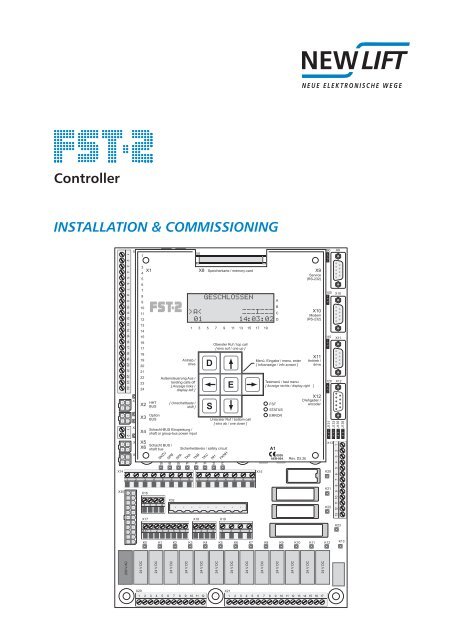
<strong>Controller</strong><br />
<strong>InstallatIon</strong> & <strong>commIssIonIng</strong><br />
X14<br />
X30<br />
230 V AC<br />
X1<br />
X2<br />
X4<br />
1<br />
3<br />
X1<br />
4<br />
5<br />
6<br />
7<br />
8<br />
9<br />
10<br />
11<br />
12<br />
13<br />
14<br />
15 J2<br />
16<br />
17<br />
18<br />
19<br />
20<br />
21<br />
22<br />
23<br />
24<br />
J1<br />
X3<br />
Option<br />
X3 BUS<br />
X.<br />
X7<br />
X2 HHT<br />
BUS<br />
X5<br />
X5<br />
X5<br />
X6<br />
Schacht BUS /<br />
shaft bus<br />
24 V DC<br />
X4<br />
X16<br />
X17<br />
SKZU<br />
SPB<br />
X32<br />
SPA<br />
TKA<br />
X8<br />
GESCHLOSSEN<br />
X20 X21<br />
>A< '''@'''<br />
01 14:03:02<br />
TKB<br />
TKC<br />
NHTL<br />
FKNHLT<br />
X15<br />
X9<br />
Service<br />
+ (RS-232)<br />
K0 K1 K2 K3 K4 K5 K6 K7 K8 K9 K10 K11 K12<br />
24 V DC<br />
[ Umschalttaste /<br />
shift ]<br />
24 V DC<br />
24 V DC<br />
X8 Speicherkarte / memory-card<br />
1 3 5 7 9 11 13 15 17 19<br />
Antrieb /<br />
drive<br />
Außensteuerung Aus /<br />
landing calls off<br />
[ Anzeige links /<br />
display left ]<br />
Schacht-BUS Einspeisung /<br />
shaft or group-bus power input<br />
Sicherheitskreis / safety circuit<br />
SKZU<br />
SPB<br />
SPA<br />
TKA<br />
TKB<br />
TKC<br />
NH<br />
FKNH<br />
X18 X19<br />
24 V DC<br />
Oberster Ruf / top call<br />
[ eins auf / one up ]<br />
Unterster Ruf / bottom call<br />
[ eins ab / one down ]<br />
24 V DC<br />
24 V DC<br />
24 V DC<br />
24 V DC<br />
A1<br />
A<br />
B<br />
C<br />
D<br />
Menü, Eingabe / menu, enter<br />
[ Infoanzeige / info screen ]<br />
FST<br />
STATUS<br />
ERROR<br />
0036<br />
AEB-004<br />
24 V DC<br />
Rev. D2.2b<br />
24 V DC<br />
X10<br />
Modem<br />
(RS-232)<br />
Testmenü / test menu<br />
[ Anzeige rechts / display right ]<br />
X12<br />
Drehgeber /<br />
encoder<br />
24 V DC<br />
X11<br />
Antrieb /<br />
drive<br />
24 V DC<br />
J90<br />
J100<br />
J110<br />
J120<br />
X9<br />
X10<br />
X11<br />
X12<br />
J131<br />
J133<br />
J135<br />
J136<br />
X13<br />
K20<br />
K21<br />
K22<br />
K23<br />
K13
Manufacturer NEW LIFT Steuerungsbau GmbH<br />
Lochhamer Schlag 8<br />
82166 Gräfelfing<br />
Phone +49 89 – 898 66 – 0<br />
Fax +49 89 – 898 66 – 300<br />
Mail info@newlift.de<br />
www.newlift.de<br />
Service line Phone +49 89 – 898 66 – 110<br />
E-mail service@newlift.de<br />
Date of issue 25.08.11<br />
Author KH / TB<br />
Release October 2010; SWB<br />
Hardware version 2.6<br />
Software version FST V1.100-0494<br />
Doc. No. mia_fst2_en<br />
Copyright © NEW LIFT Steuerungsbau GmbH, 2010.<br />
This manual is protected by copyright. All rights, including those of copying, of<br />
reproduction, of translation and of modification, in whole or in part, are reserved by<br />
the publisher.<br />
No part of this description may be reproduced in any form or copied with an<br />
electronic replication system without written permission.<br />
Although great care has been taken in the production of texts and figures, we<br />
cannot be held legally liable for possible mistakes and their consequences.<br />
B Installation & Commissioning FST-2
Contents<br />
1 About this manual 1<br />
1.1 General 1<br />
1.2 Signs and symbols used 1<br />
1.3 Further information 2<br />
1.4 How to contact us 2<br />
2 General safety regulations 3<br />
2.1 Qualifications of the installing engineer 3<br />
2.2 Residual dangers 3<br />
2.3 Safety regulations 4<br />
3 FST controller user interface 6<br />
3.1 Keypad functions 6<br />
3.1.1 When switching on 6<br />
3.1.2 Main screen 7<br />
3.1.3 Main menu and test menu 7<br />
3.1.4 Error list 8<br />
3.1.5 Information page 8<br />
3.1.6 Frequency inverter with DCP interface 8<br />
3.2 LC-Display and messages 8<br />
3.2.1 Main screen 8<br />
3.2.2 Line A – Safety circuit messages 9<br />
3.2.3 Line B – State messages 9<br />
3.2.4 Line C – Status messages 11<br />
3.2.5 Line C - Diagnostic messages 12<br />
3.2.6 Line D - Drive mode messages 12<br />
3.3 Information texts 12<br />
3.3.1 Information page 14<br />
3.4 LEDs 15<br />
4 Installation work 16<br />
4.1 Installation procedure 16<br />
4.2 Delivery contents 17<br />
4.3 Control cabinet 17<br />
4.4 Travelling cable 19<br />
4.5 car components 20<br />
4.5.1 Car top box 20<br />
4.5.2 FPM-1 21<br />
4.5.3 FPM-2 21<br />
4.6 Switching on the controller 22<br />
4.6.1 FST 22<br />
4.6.2 Checking the safety circuit 22<br />
4.6.3 Switching on installation mode 22<br />
4.6.4 car components 23<br />
Installation & Commissioning FST-2 I
4.7 Installation drive 23<br />
4.7.1 Installing the positioning system 23<br />
4.7.2 Installing magnet switch console and magnets 24<br />
4.7.3 Connecting the LON bus 26<br />
5 Determination of the shaft positioning system 28<br />
5.1 Absolute positioning 28<br />
5.2 Incremental positioning 29<br />
6 Commissioning the FST 30<br />
6.1 Commissioning procedure 30<br />
6.2 Commissioning absolute positioning 31<br />
6.2.1 Setting the type of shaft positioning system 31<br />
6.2.2 Checking the direction of rotation of the encoder 31<br />
6.2.3 Checking / setting the resolution of the encoder 31<br />
6.2.4 Setting bottom floor to 0 33<br />
6.3 Commissioning incremental positioning 34<br />
6.3.1 Setting the type of shaft positioning system 34<br />
6.3.2 Checking the direction of rotation of the encoder 34<br />
6.3.3 Checking / setting the resolution of the encoder 34<br />
6.3.4 Configuring the incremental encoder 36<br />
6.3.5 Setting bottom floor to 0 36<br />
6.3.6 Carrying out learn drive 37<br />
6.4 Carrying out calibration drive 38<br />
6.4.1 Checking positioning accuracy 39<br />
6.5 Levelling adjustment 39<br />
6.5.1 Levelling adjustments on the FST controller 40<br />
6.5.2 Levelling adjustment via HHT handheld terminal 40<br />
6.5.3 Level adjustment via FPM-1 or FPM-2 41<br />
6.6 Commissioning the safety circuit bypass control 41<br />
6.6.1 Operating principle of the safety circuit bypass control 42<br />
6.6.2 Checking the safety circuit bypass control 42<br />
6.6.3 Optimising re-levelling 43<br />
6.6.4 Readjustment 43<br />
6.7 Setting control options 43<br />
6.7.1 Password 43<br />
6.7.2 Crawl drive 44<br />
6.7.3 Door times 44<br />
6.7.4 Test triggering of the monitoring function according to EN 81 45<br />
6.7.5 LON module configuration 47<br />
6.7.6 CMM activation 51<br />
6.7.7 Emergency call filter 51<br />
6.7.8 Creating & loading a backup 51<br />
7 Pin assignment components 52<br />
7.1 FST 52<br />
7.1.1 FST Jumpers 52<br />
7.1.2 FST Terminal strips and sockets 53<br />
II Installation & Commissioning FST-2
7.2 FSM-2 58<br />
7.2.1 FSM-2 Jumpers 58<br />
7.2.2 FSM-2 Terminal strips and sockets 59<br />
7.3 FPM-1 63<br />
7.3.1 FPM-1 Jumpers 63<br />
7.3.2 FSM-1 Terminal strips and sockets 64<br />
7.4 FPM-2 65<br />
7.4.1 FPM-2 Jumpers 66<br />
7.4.2 FSM-2 terminal strips and sockets 66<br />
7.5 EAZ-256/40 and EAZ-256/64 68<br />
7.5.1 EAZ-256/40 and EAZ-256/64 Jumpers 68<br />
7.5.2 EAZ-256/40 and EAZ-256/64 terminal strip 69<br />
7.6 ADM-S and ADM-D 69<br />
7.7 ADM-XF and ADM-XK 70<br />
7.7.1 ADM-XF and ADM-XK Jumpers 70<br />
7.7.2 ADM-XF and ADM-XK Terminal strips sockets 71<br />
8 Commissioning the FST GROUP 72<br />
8.1 General 72<br />
8.2 LEDs FST GROUP 72<br />
8.3 Commissioning steps 73<br />
8.3.1 Switching on the GST controller board 73<br />
8.3.2 Checking basic settings on the GST controller board 73<br />
8.3.3 Checking basic settings in FST controllers 74<br />
8.3.4 Establishing bus connections 76<br />
8.3.5 Check the status of the systems 76<br />
8.3.6 Initialising GST controller board 76<br />
8.3.7 Testing group function 77<br />
9 Error list 78<br />
9.1 Error messages 78<br />
9.2 Event messages 84<br />
10 Notes 86<br />
Installation & Commissioning FST-2 III
IV Installation & Commissioning FST-2
1 About this manual<br />
About this manual<br />
General<br />
Read these instructions carefully before installing and commissioning the FST controller. In addition, chapter „2<br />
General safety regulations“ on page 3 must be observed. Operation of the FST controller is briefly explained in<br />
chapter „3 FST controller user interface“ on page 6.<br />
1.1 General<br />
This manual will help you during installation and commissioning of the FST controller and its components.<br />
The installation and commissioning manual contains important information for safe and proper installation and<br />
commissioning of the FST controller.<br />
Following these instructions will help to:<br />
› prevent danger,<br />
› avoid repair costs and downtime,<br />
› increase the reliability and lifespan of the FST controller and of the lift system.<br />
Local, national and on-site regulations regarding health and safety and protection of the environment must be<br />
taken into account in addition to this installation and commissioning manual.<br />
This manual only describes the assemblies of the lift system delivered by NEW LIFT. For information about<br />
components of the lift system that were not manufactured and supplied by NEW LIFT, please refer to the respective<br />
user information supplied by the manufacturer or supplier.<br />
1.2 Signs and symbols used<br />
The following signs and symbols are used for operational instructions:<br />
Symbols<br />
Delivery condition<br />
Settings that are supplied as standard are marked with an asterisk .<br />
System stop<br />
Marks settings requiring a system stop in case a change becomes necessary. The FST controller displays the<br />
text <strong>Lift</strong> must be stopped to change the value. OK? If you wish to change the value, confirm with<br />
YES, if you do not wish to change the value or wish to change it later, then confirm with NO.<br />
○ Re-start<br />
Marks settings that only become active after a re-start of the FST or of the components.<br />
► Activity symbol:<br />
Activities described after this symbol must be carried out in the given order.<br />
+ Key combination:<br />
Press the linked keys simultaneously.<br />
Abbreviation used for detailed terminal information<br />
P: power<br />
I: input<br />
O: outpur<br />
L: low active<br />
H: high active<br />
Safety-relevant information<br />
This symbol is located in front of safety-relevant information.<br />
Information notice<br />
This symbol is located in front of relevant information.<br />
Installation & Commissioning FST-2 1
About this manual<br />
Further information<br />
1.3 Further information<br />
The following documents, among others, are available for the FST controller and its components:<br />
› FST controller description<br />
› FST manual<br />
› FST short instructions<br />
› FST GROUP manual<br />
› ADM manual<br />
› EAZ-256 manual<br />
› EAZ-LCD and EAZ-VFD manual<br />
› EAZ-TFT manual<br />
› LCS manual<br />
› SAM manual<br />
› Fire recall manual<br />
These and other manuals can be found in the download area of our website under Service.<br />
1.4 How to contact us<br />
If, after referring to this manual, you still require assistance, our service line is there for you:<br />
Phone +49 89 – 898 66 – 110<br />
E-mail service@newlift.de<br />
Mon. - Thurs.: 08:00 a.m. – 12:00 p.m. and 1:00 p.m. – 5:00 p.m.<br />
Fr: 08:00 a.m. – 12:00 p.m. and 12:30 – 3:00 p.m.<br />
2 Installation & Commissioning FST-2
2 General safety regulations<br />
General safety regulations<br />
Qualifications of the installing engineer<br />
All important safety regulations are summarised in this chapter. These safety instructions must always be adhered<br />
to during all work on the installation.<br />
All persons performing installation and commissioning work on the FST controller must read this chapter and<br />
follow its regulations.<br />
Laws, regulations, guidelines and standards that apply in the country of operation must be followed in addition<br />
to the safety regulations mentioned in this manual.<br />
2.1 Qualifications of the installing engineer<br />
The installing engineer must:<br />
› be over 18 years of age (exception: apprentices who are over 16 years of age and are permanently supervised<br />
by an engineer qualified for training apprentices).<br />
› have first aid training,<br />
› have theoretical and practical knowledge of regulations and measures for the prevention of fire and explosions<br />
in his work area,<br />
› be able to identify, avoid and rectify all dangers that might occur during his work in the shaft and in the operating<br />
rooms,<br />
› be able to identify and rectify all irregularities and faults that might occur during installation and operation of a lift<br />
system,<br />
› have theoretical and practical knowledge of operating principles and requirements of electric controls and drive<br />
systems.<br />
All installation and commissioning work on electric and electronic components of the FST controller must be<br />
performed by or supervised by a qualified electrician.<br />
A qualified electrician has appropriate training and knowledge of regulations that allow him to judge the quality<br />
of the work performed and identify possible dangers (BGV A3).<br />
2.2 Residual dangers<br />
Danger for persons<br />
The following shall always apply during all work on the installation:<br />
Danger to life! Do not touch live parts while working on electrical equipment.<br />
› Before starting work, make sure the system is off circuit.<br />
› Only carry out any installation work on electrical components when these are switched off and in an unpowered<br />
state.<br />
› Only use insulated tools when working on electrical system components.<br />
Risk of injury when lifting or moving the control cabinet if it falls down or tips over.<br />
› Only transport and lift the control cabinet with suitable equipment (lift truck, hoisting gear etc.).<br />
› All workers must be trained in using these aids and must observe all applicable special regulations to avoid<br />
accidents.<br />
Falling parts or parts protruding into the shaft. Risk of serious injury or death.<br />
› Block the shaft access points.<br />
› Before beginning installation work, remove all foreign parts and assembly aids that are not required from the<br />
shaft.<br />
Electrical hazard, leaking gas or water due to pierced supply lines. Risk of serious injury or death.<br />
› Make sure no supply lines are in the installation location before starting any installation work.<br />
Installation & Commissioning FST-2 3
General safety regulations<br />
Safety regulations<br />
Danger of falling! Installing engineers and unauthorised persons can fall down the shaft. Risk of serious injury or<br />
death.<br />
› Block the shaft access points.<br />
› Use suitable protection (e.g. safety harnesses, scaffoldings) when working on or in the shaft.<br />
Danger of crushing due to intentional or accidental car movement. Risk of serious injury or death.<br />
› Block the shaft access points.<br />
› Before starting any work, make sure that there are no persons in the shaft or in the vicinity of moving parts of<br />
the drive.<br />
› Prevent unauthorised operation of the controller.<br />
Risk of material damage<br />
The following shall always apply during all work on the installation:<br />
Electrostatic charging<br />
› Keep the electronic assembly in its original packaging until installation.<br />
› Before opening the original packaging, a static discharge must be performed. To do this, touch a grounded<br />
piece of metal.<br />
› During work on electronic assemblies, periodically perform this discharge procedure.<br />
Electronic assemblies are destroyed by defective, interchanged or incorrectly mounted connectors, short-circuiting<br />
or excess voltage.<br />
› Check plugs for mechanical damage.<br />
› Never change pre-assembled connectors or cables.<br />
› Only connect loose or torn off wires according to circuit diagram details if this is possible on site (suitable material<br />
and tools must be available).<br />
› Pay attention to coding pins and latch lugs.<br />
2.3 Safety regulations<br />
General<br />
› The instructions of the lift manufacturer and the instructions in this manual must be followed during installation<br />
and commissioning of the lift system.<br />
› The shaft must be secured against unauthorised trespassing during installation and commissioning.<br />
› Assemblies, devices and cables must be installed and fastened securely and permanently.<br />
› Loads must be moved with suitable aids (lift trucks, hoisting gear etc.).<br />
› Sharp and pointed tools or other potentially dangerous objects may only be carried along in clothing if suitable<br />
protective measures have been taken to rule out any danger.<br />
› Alcohol and drugs must not be consumed before and during installation and commissioning.<br />
Documentation<br />
› A copy of the installation and commissioning manual must be available to the installing engineer at the time of<br />
installing and commissioning the FST controller and its components.<br />
› A copy of the installation and commissioning manual and the wiring diagrams must be kept in the control cabinet<br />
at all times after installation.<br />
› The wiring diagrams supplied with the FST controller are binding. Changes must only be made after consulting<br />
NEW LIFT and must be documented in writing on the system.<br />
› The factory test logs of the FST controller remain with NEW LIFT.<br />
Electricity<br />
› Regulations for installing and operating electrical equipment (VDE 0100) and regulations of local utilities must<br />
be followed.<br />
› The specified distances between different electrical assemblies must be controlled and maintained.<br />
› All installation work must be carried out with the system shut down and off circuit.<br />
› All cables and wires must be installed with sufficient strain relief.<br />
› The neutral and ground wires must be routed separately.<br />
› The control cabinet must be supplied with a clockwise rotary field.<br />
4 Installation & Commissioning FST-2
Working in the shaft<br />
General safety regulations<br />
Safety regulations<br />
› Any work in the shaft requires perfect and permanent communication between the supervisor on the FST controller<br />
in the motor room and the workers in the shaft.<br />
› Components in the shaft must be arranged or secured in such a way that persons accessing the shaft for inspection,<br />
maintenance or repair purposes are not in danger.<br />
› The maximum load of the lift system must not be exceeded.<br />
› The specified overruns of the emergency end switches in relation to the speed must be observed.<br />
› The emergency installations must not be activated during normal operation.<br />
› All emergency installations and braking systems must be checked for troublefree operation and all shaft entrances<br />
closed off before beginning work.<br />
› Installation and operation are prohibited if other persons could be in danger.<br />
› Workers must be secured against falling.<br />
› In case of any work interruptions, the car must be moved to the lowest stop position, the controller switched off<br />
and the power supply (e.g. UPS) permanently disconnected.<br />
Personal safety equipment of the installing engineer<br />
› Eye protection<br />
› Safety boots<br />
› Protective helmet<br />
› Safety harness<br />
› Clothing suitable to the ambient conditions of the installation location<br />
› Jewellery, watches and similar items may not be worn; a hair net must be used if applicable.<br />
Handling electronic assemblies<br />
› Leave electronic assemblies in their original packaging until installation.<br />
› Touch a grounded piece of metal prior to opening the original packaging to prevent damage from static charges.<br />
› All bus inputs and outputs not in use must be equipped with a terminal resistor (terminator). Exception: FSM-2<br />
X23 and FST X2 are only for use with the HHT hand-held terminal and must not be equipped with a terminator.<br />
Waste disposal<br />
› All packaging material must be disposed of in an environmentally acceptable manner; paper, plastic, metal,<br />
electronic assemblies etc. must be recycled.<br />
Installation & Commissioning FST-2 5
FST controller user interface<br />
Keypad functions<br />
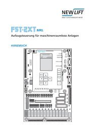
3 FST controller user interface<br />
The user interface of the FST controller is located on the FST main circuit board in the control cabinet of the lift<br />
system. The FST user interface consists of front panel, LC-Display, keypad and LEDs.<br />
1<br />
3<br />
X1<br />
4<br />
5<br />
6<br />
7<br />
8<br />
9<br />
10<br />
11<br />
12<br />
13<br />
14<br />
15<br />
16<br />
17<br />
18<br />
19<br />
20<br />
21<br />
22<br />
23<br />
24<br />
X2 HHT<br />
BUS<br />
X3<br />
X4<br />
X5<br />
X6<br />
Option<br />
BUS<br />
[ Umschalttaste /<br />
shift ]<br />
Speicherkarte / memory-card<br />
1 3 5 7 9 11 13 15 17 19<br />
Antrieb /<br />
drive<br />
Außensteuerung Aus /<br />
landing calls off<br />
[ Anzeige links /<br />
display left ]<br />
Schacht-BUS Einspeisung /<br />
shaft or group-bus power input<br />
Schacht BUS /<br />
shaft bus<br />
Fig. 3.1: FST controller user interface<br />
3.1 Keypad functions<br />
X8<br />
Sicherheitskreis / safety circuit<br />
SKZU<br />
SPB<br />
SPA<br />
TKA<br />
TKB<br />
TKC<br />
NH<br />
FKNH<br />
The FST controller is operated using seven keys.<br />
3.1.1 When switching on<br />
SAFETY CCT CLOSED<br />
>AX< >BX< '''@'''<br />
00 13:06:56<br />
Oberster Ruf / top call<br />
[ eins auf / one up ]<br />
Unterster Ruf / bottom call<br />
[ eins ab / one down ]<br />
Rev. D2.2b<br />
6 Installation & Commissioning FST-2<br />
A1<br />
A<br />
B<br />
C<br />
D<br />
Menü, Eingabe / menu, enter<br />
[ Infoanzeige / info screen ]<br />
FST<br />
STATUS<br />
ERROR<br />
0036<br />
AEB-004<br />
X9<br />
Service<br />
(RS-232)<br />
X10<br />
Modem<br />
(RS-232)<br />
X11<br />
Antrieb /<br />
drive<br />
Testmenü / test menu<br />
[ Anzeige rechts / display right ]<br />
X12<br />
Drehgeber /<br />
encoder<br />
S Pressing and holding the S key during the switch-on sequence of the FST starts emergency<br />
operation. In emergency operation, no drives are possible. Emergency operation is required if the<br />
FST cannot be switched on in normal mode due to a malfunction. The complete FST menu and the<br />
PC-Card functions are active in emergency operation!
3.1.2 Main screen<br />
SAFETY CCT CLOSED<br />
'''@'''<br />
00 13:06:56<br />
£<br />
¢<br />
¥<br />
¤<br />
E<br />
S<br />
S+£<br />
S+¢<br />
S+¤<br />
S+¥<br />
S+E<br />
S+¥+¤<br />
£+¢+¥+¤<br />
D<br />
Set car call to top floor<br />
Set car call to bottom floor<br />
Switch landing control on and off (switch function)<br />
Open test menu<br />
Open main menu<br />
FST controller user interface<br />
Keypad functions<br />
Activate emergency mode: press before switching on and keep pressed until the FST has<br />
fully run up (see FST manual)<br />
Set car call to next floor up<br />
Set car call to next floor down<br />
Scroll through the right status messages in line C<br />
Scroll through the left status messages in line C<br />
Display information page<br />
Switch diagnostic message in line C on or off<br />
Perform controller RESET<br />
3.1.3 Main menu and test menu<br />
MAIN MENU<br />
Drive<br />
Config<br />
>Positioning<br />
£<br />
¢<br />
¥<br />
¤<br />
E<br />
Clock Setting<br />
13:45:01<br />
£<br />
¢<br />
¥<br />
¤<br />
E<br />
Move cursor up<br />
Move cursor down<br />
Exit submenu<br />
Change menu level<br />
Switch to converter menu (DCP)<br />
Select submenu / menu item<br />
Increase value<br />
Decrease value<br />
Move cursor left<br />
Move cursor right<br />
Confirm setting<br />
Installation & Commissioning FST-2 7
FST controller user interface<br />
LC-Display and messages<br />
3.1.4 Error list<br />
ERROR[00037/00040]<br />
28.09 10:18:26 [012]<br />
Door close failure<br />
FLOOR:03 V00 R01 I00<br />
¢<br />
£<br />
S+£<br />
S+¢<br />
Switch to 2nd to 8th information byte in line D<br />
Switch to initial display in line D<br />
To previous error message<br />
To next error message<br />
3.1.5 Information page<br />
- FST Information -<br />
HW Ver.: 12-16<br />
SW VER:: V 1.100-0026<br />
18/05/1999<br />
£<br />
¢<br />
E<br />
Scroll one line up<br />
Scroll one line down<br />
Back to main screen<br />
3.1.6 Frequency inverter with DCP interface<br />
D<br />
Frequency inverters with DCP interface can be operated and configured from the FST menu (FST<br />
X11 connected). The display of the frequency inverter is simulated on the FST display by pressing the<br />
D-key once. The FST keys then perform the function of the frequency inverter keys. The FST display<br />
is restored by pressing the D-key again.<br />
3.2 LC-Display and messages<br />
The LC-Display consists of four lines (A, B, C and D) with 20 columns each. After switching on and during normal<br />
operation, the FST controller displays the main screen.<br />
3.2.1 Main screen<br />
SAFETY CCT CLOSED<br />
>AX< '''@'''<br />
00 13:06:56<br />
A Maximum active state of the safety circuit<br />
B Active state or error<br />
C Status of the lift system / diagnostic message<br />
D Data for current drive mode<br />
Line C has a special status. In normal mode (after switching on), it displays status messages (see „3.2.4 Line<br />
C – Status messages“ on page 11). By switching with key combination s+¥+¤, it displays diagnostic messages<br />
(see „3.2.5 Line C - Diagnostic messages“ on page 12).<br />
See also „3.1 Keypad functions“ on page 6.<br />
8 Installation & Commissioning FST-2
3.2.2 Line A – Safety circuit messages<br />
FST controller user interface<br />
LC-Display and messages<br />
Display Description<br />
SAFETY CCT CLOSED The safety circuit is completely closed (FST X14.1, FST X14.2).<br />
SFTY-CLOSED MISSING The input "Safety circuit closed" has no power. Possible causes:<br />
› Terminal FST X14.1 has no power (normally bridged with X14.2)<br />
› Relay K14 (230V) on the FST is faulty<br />
DOOR LOCK-A OPEN The shaft door contact of door side A is interrupted (FST X14.2, X14.3) .<br />
DOOR LOCK-B OPEN The shaft door contact of door side B is interrupted (FST X14.3, X14.4) .<br />
DOOR A OPEN<br />
The car door contact of side A is interrupted (FST X14.4, X14. 5).<br />
DOOR B OPEN<br />
The car door contact of side B is interrupted (FST X14.5, X14. 6).<br />
DOOR C OPEN<br />
The car door contact of side C is interrupted (FST X14.6, X14. 7).<br />
MANUAL DOOR OPEN A manual door contact is interrupted (FST X14.6, X14.7).<br />
EMERGENCY STOP An emergency switch in the shaft is interrupted (terminals FST X14.7, X14.8).<br />
EMERGENCY STOP CAR An emergency switch on the car is interrupted (FST X32.4).<br />
The messages DOOR C OPEN, MANUAL DOOR OPEN and EMERGENCY END SWITCH (line B) are triggered by<br />
the same safety circuit input of the FST (TC input: FST X14. 6) and exclude each other.<br />
3.2.3 Line B – State messages<br />
Display Description<br />
LOW 24 V!<br />
The 24V power supply of the FST board (FST X1.1, X1.2) is below the permitted<br />
range of 17 V. Check power supply and cables in the supply line.<br />
POST-EMERGENCY STOP Landing control is blocked by a safety circuit interruption (interruption before<br />
terminal FST X32.4), line A displays EMERGENCY STOP.<br />
LANDING CONTROL OFF The landing control has been switched off manually. Possible causes of the<br />
shutdown:<br />
› › ¥ Key of the FST keypad<br />
› Programmable input of an external RIO module<br />
› Input FST X1.14<br />
› Programmable input on the FST controller<br />
› Key switch on car panel (FPM-1 X4.37 / FPM-2 X1.13)<br />
› Key switch on landing control panel (ADM input X3.12 / X3.13)<br />
FIREMAN MODE<br />
A fire input is active. Possible causes of fire recall:<br />
› Fire input on landing call module (ADM input X3.12 / X3.13)<br />
› Programmable input on the FST controller<br />
› GST Group <strong>Controller</strong> (see GST manual)<br />
END-SWITCH TEST The manual end-switch test is being executed (see test menu in the FST<br />
manual).<br />
ES-SPEED MON. TEST The manual test of the deceleration monitoring function at the top and bottom<br />
end floors is running (see test menu in the FST manual).<br />
EVACUATION<br />
The controller is in evacuation mode. The reason for the evacuation signal may<br />
be:<br />
› A programmable input on the FST controller<br />
› A programmable input on the GST Group <strong>Controller</strong><br />
› LMS via protocol adapter module<br />
SEND FAX<br />
The controller is in fax mode (see Installation & Commissioning – Fax modem).<br />
LIFT OFF<br />
The controller has been switched off. Possible causes of switch-off:<br />
› Car lighting failure<br />
› Input "Car Lighting OFF", FST X1.13<br />
› Programmable I/O port of a RIO module (external)<br />
› Programmable I/O port of the FST controller<br />
› Externally by the GST Group <strong>Controller</strong> or the LMS <strong>Lift</strong> Monitoring System<br />
Installation & Commissioning FST-2 9
FST controller user interface<br />
LC-Display and messages<br />
Display Description<br />
FIREMAN SERVICE Fireman service mode has been activated. Possible causes of signal:<br />
› Key switch fireman service in car operating panel (FPM-1 X4.4 / FPM-2 X2.13)<br />
› Programmable I/O port of the FST controller<br />
› The state was saved after a power failure and has been reconstructed. The<br />
Fireman Mode Reset function must be executed to reset this state.<br />
› Key switch on landing control panel (ADM input X3.12 / X3.13)<br />
› GST Group <strong>Controller</strong> (see GST manual)<br />
FILE TRANSFER ACTIVE The controller is in data transmission mode to transfer files to a GST Group <strong>Controller</strong><br />
or to a PC.<br />
Attendant operation The attendant controller is active.<br />
INSPECTION MODE The controller is in inspection mode (input FSM-2 X22.2).<br />
Attention: Line A of the FST display must show EMERGENCY STOP CAR!<br />
CALIBRATION -- The calibration drive has been started. A ticker text displays the status.<br />
After completion of a successful calibration drive, the message CALIBRATION<br />
OK! appears. If the drive is interrupted prematurely, CALIBRATION ABORT!<br />
appears. Find the error in the error list and repeat the calibration drive<br />
APRON-EXTENDED! The car apron is open (due to a shaft door interruption). Monitoring is performed<br />
via a programmable input on the FST controller.<br />
LEARN DRIVE ACTIVE The controller performs a learn drive.<br />
LEARN DRIVE-START The controller starts a learn drive.<br />
LEARN DRIVE-OK! The learn drive has been completed successfully.<br />
LEARN DRIVE-ABORT! The learn drive has been aborted due to an error. Find the error in the error list<br />
and repeat the learn drive.<br />
SAFETY CURTAIN The safety curtain replacing the car door has been interrupted. The contact is<br />
in the safety circuit instead of the car door contacts (see System description –<br />
Safety curtain).<br />
DRM ...<br />
A runtime monitoring error has occurred, the installation is brought to a standstill.<br />
Possible causes are, amongst others:<br />
› Start-up problems<br />
› Runtime monitoring<br />
› Encoder failure<br />
› car communication<br />
› Motor failure<br />
› Forced stop<br />
› Emergency end switch<br />
› Door failure<br />
INSTALLATION MODE The controller is in installation mode.<br />
EMERGENCY END SWITCH The top emergency end switch is interrupted (FST X14.6, X14.7)<br />
ORIENTATION<br />
Only incremental positioning:<br />
After switching on, the controller performs an orientation drive to an end floor.<br />
The orientation drive can take place automatically or when the first call is placed.<br />
PARKING ACTIVE The controller sends the car to the programmed parking floor.<br />
LANDING PRIORITY A priority landing drive has been triggered. Possible causes of signal:<br />
› Key switch on landing control panel (ADM input X3.12 / X3.13)<br />
› Programmable input on the FST controller<br />
› Programmable input on an external RIO module<br />
CAR PRIORITY<br />
A priority car drive has been triggered. Possible causes of signal:<br />
› Key switch on car panel (FPM-1 X4.37 / FPM-2 X1.13)<br />
› Automatically after a type Auto 2 priority landing drive<br />
AUXILIARY MODE The controller is in auxiliary mode (input FST X18.2).<br />
Attention: Line A of the FST display must show EMERGENCY STOP!<br />
HOMING ACTIVE The hydraulic lift is sent to the lowest landing.<br />
SERVICE MODE<br />
The controller is in service mode (see test menu in the FST manual).<br />
SERVICE REQUIRED! One of the service counters has exceeded a set limit.<br />
SYSTEM STOP<br />
The controller has been stopped via the FST menu.<br />
OVER LOAD<br />
The overload input on the FSM or on a programmable input is active.<br />
10 Installation & Commissioning FST-2
FST controller user interface<br />
LC-Display and messages<br />
Display Description<br />
USER ERROR<br />
A user error has occurred (you can define up to three error messages as user<br />
errors). The number of the error is displayed.<br />
V.I.P. MODE<br />
The controller is in VIP mode. The source for the VIP mode can be:<br />
› LMS via protocol adapter module<br />
› Programmable input on the FST controller<br />
› FPM-2 X2.14 in the car operating panel<br />
FULL LOAD<br />
The full load input on the FSM is active.<br />
3.2.4 Line C – Status messages<br />
Line C is divided into two parts and displays one of the following status messages in the left part and one in the<br />
right part. This way you can select which two status messages you want shown simultaneously on the display.<br />
Select the status message in the left-hand area with S+¥, in the right-hand area with S+¤.<br />
Status Display Description<br />
Car doors Door A completely open<br />
>A<<br />
Door A completely closed<br />
{A}<br />
Door A is opening<br />
}A{<br />
Door A is closing<br />
<br />
Photocell or reversing contact door A active<br />
<br />
Door A is locked (test menu)<br />
<br />
Door is in loading mode (loading button has been pressed)<br />
-A-<br />
Door A is stopped<br />
?A?<br />
State of door A is unknown (check door end switches)<br />
{{}}<br />
Door open button active<br />
}}{{<br />
Door close button active<br />
<br />
Door open button permanently pressed<br />
>}{<<br />
Door close button permanently pressed<br />
Shaft positioning Z Zone message active<br />
F<br />
Zone message missing<br />
-<br />
Car is in levelled position<br />
'''@'' Car position relative to level position (2.5 mm / pixel)<br />
†<br />
Bottom correction switch active<br />
°<br />
Top correction switch active<br />
Car position P=6200 Current car position in relation to the level position of the bottom<br />
floor in mm.<br />
Levelling Pd= -2 Current position of the car relative to closest level position in<br />
[mm]<br />
Car speed V=1300 Current speed of the car in [mm/s]<br />
Set / actual speed '''''''-- Comparison between set and actual speed of the car. The left<br />
bar is a graphic display of the relation between actual speed and<br />
the set speed on the right. (Only displayed if no level position is<br />
displayed in the other area)<br />
Motor-Hours BS=4351 Operating hours of the drive<br />
Drive counter FZ=123456 Number of completed drives<br />
Load measurement L=100 kg Displays the current car load (only in combination with LCS)<br />
Memory occupied Rec: 45% Memory occupied on the PC-Card when recording.<br />
The door states marked with A also apply to doors B and C.<br />
Installation & Commissioning FST-2 11
FST controller user interface<br />
Information texts<br />
3.2.5 Line C - Diagnostic messages<br />
Line C can be switched from status messages to diagnostic messages with key combination S+¥+¤. You will<br />
find further information in the FST manual.<br />
3.2.6 Line D - Drive mode messages<br />
Column Display Description<br />
1 T Auto test drive active<br />
S<br />
No serial connection to the frequency inverter (FST X11)<br />
s<br />
Data transmission to the frequency inverter via serial connection is faulty (FST<br />
X11)<br />
2 ` Direction of travel UP<br />
\<br />
Direction of travel DOWN<br />
3-4 10 Current floor for the car<br />
5-8 [13] car call and landing call on target floor<br />
[13<br />
car call to target floor<br />
13]<br />
Landing call to target floor<br />
X13<br />
car control blocked<br />
13X<br />
Landing control blocked<br />
9 Not assigned<br />
10 G FST is integrated in a GST Group <strong>Controller</strong>.<br />
g<br />
FST is integrated in a GST Group <strong>Controller</strong> but communication with the GST is<br />
faulty<br />
s<br />
"Separated" group participants<br />
P<br />
Drive temporarily stopped<br />
11 R Flashes while recording data on the PC card<br />
F<br />
Card is cleared<br />
B<br />
Bank controller: user group active<br />
9-11 FTX Data exchange from FST active (from FST to GST, LMS, etc.)<br />
FRX<br />
Data exchange to FST active (from GST, LMS, etc. to FST)<br />
12 Not assigned<br />
13-20 10:44:12 Current time of the FST<br />
3.3 Information texts<br />
When triggering actions in the FST menu, information texts may appear in the display. They contain information<br />
on the result of the respective action.<br />
Display Description<br />
EMERGENCY MODE!<br />
The controller is in emergency mode. Drives are not possible. Emergency<br />
operation is activated by pressing the S key while switching the<br />
system on.<br />
Landing call button stuck:<br />
03/A<br />
Car-call button stuck: 02/B<br />
ADM unconfigured!<br />
DRIVE INHIBIT ON!<br />
Please Wait!<br />
REMOVE WRITE-PROTECT<br />
FAX/SMS SENT OK!<br />
The landing call from the specified floor and door side is permanently<br />
activated (is stuck). The message is repeated every minute until the<br />
error has been corrected.<br />
A landing call module connected to the shaft bus is not configured.<br />
Inform NEW LIFT service line!<br />
Mutual start-up blocking via the LMS bus is active. Starting will be<br />
delayed until the other networked systems have completed their acceleration<br />
phases.<br />
The triggered action has not been completed. Please wait!<br />
The PC-Card is write-protected. Move the door lock on the PC card to<br />
disable the write protect function.<br />
A status fax was sent successfully via the modem interface.<br />
12 Installation & Commissioning FST-2
FST controller user interface<br />
Information texts<br />
Display Description<br />
FAX/SMS -> GST!<br />
A fax/SMS (text message) is sent to the group controller where it will<br />
be sent via the FAX-modem.<br />
FAX/SMS NOT SENT!<br />
Transmission of a status fax via the modem interface was aborted.<br />
Check modem and telephone connection. MAIN MENU / Config /<br />
Modem/Fax/LMS<br />
FILE NOT FOUND!<br />
The inserted PC-Card does not contain the file(s) required for the<br />
triggered action.<br />
FST Software Update<br />
The software of the FST is updated with the PC-Card. The progress in<br />
[%] is displayed in line C.<br />
GST UPDATE COMPLETE!<br />
The software update of the GST Group <strong>Controller</strong> has been completed<br />
successfully.<br />
ZONE IS INCORRECT!<br />
The zone measured during the learn drive is too long (max - 300mm to<br />
+300mm)<br />
Calibration abort!<br />
The calibration drive was aborted. Check function of connected drive<br />
speeds. Locate reason for drive abort in the error list.<br />
NO SIGNAL<br />
The car is on the top floor and the correction top signal is missing (only<br />
incremental positioning). Check function of TC switch. Check settings<br />
in MAIN MENU / Positioning / Increm. Positioning. /<br />
TC/BC level.<br />
NO SIGNAL!<br />
The car is on the bottom floor and the correction bottom signal is<br />
missing (only incremental positioning). Check function of BC switch.<br />
Check settings in MAIN MENU / Positioning / Increm. Positioning.<br />
/ TC/BC level.<br />
CONFIG TRANSFER ERR!<br />
An error has occurred during copying of the controller configuration.<br />
CONFIG TRANSFER OK!<br />
<strong>Controller</strong> configuration copied successfully.<br />
CONFIG(D) CORRUPT!<br />
A parameter of the drive configuration is not plausible. Change a<br />
parameter in MAIN MENU / Drive and undo the change again. The<br />
information text disappears after saving the settings.<br />
CONFIG(S) CORRUPT!<br />
A parameter of the system configuration is not plausible. Change a<br />
parameter in MAIN MENU / Config and undo the change again. The<br />
information text disappears after saving the settings.<br />
LCS (L1) calibrated!<br />
The LCS empty load measurement was performed.<br />
LCS (L2) calibrated!<br />
The LCS reference load measurement was performed.<br />
LEARN DRIVE FAILURE!<br />
The started learn drive was not successful. Check function of signals<br />
zone B, bottom correction (BC) and top correction (TC). Locate reason<br />
for drive abort in the error list.<br />
LEARN DR. START FAILURE! The started learn drive was aborted due to the car not moving even<br />
with pre-selection active.<br />
DRV–TEST STARTED!<br />
A DRV test was triggered.<br />
DRV–TEST FINISHED!<br />
The DRV test was not completed successfully.<br />
CAR NUISANCE DETECT!<br />
The car nuisance protection function has triggered.<br />
See MAIN MENU / Config / Anti Nuisance.<br />
NOT IN THE ZONE!<br />
The started learn drive cannot be performed because the car is not in<br />
the door zone of the bottom floor. Check function of zone B signal and<br />
settings in MAIN MENU / Positioning / Increm. Positng. /<br />
ZoneB-Level.<br />
NOT IN FLOOR-0!<br />
The started learn drive cannot be completed because the car is not on<br />
the bottom floor (check bottom correction switch, BC)<br />
NOT FROM THIS FLOOR!<br />
The car is at an end floor. The end switch test cannot be started from<br />
this floor.<br />
EMERG.-CALL PRESSED<br />
An emergency call button was pressed or is defective (see wiring<br />
diagram).<br />
ONLY FROM END FLOOR!<br />
The triggered DRV test can only be started from an end floor.<br />
PC-CARD REMOVED!<br />
The inserted PC-Card was removed from slot X8.<br />
PC-CARD FLASH TYPE??<br />
The memory type of the inserted PC-Card is unknown to the controller.<br />
PC-CARD TYPE????!<br />
The PC-Card cannot be used. Please contact NEW LIFT.<br />
PC-CARD EMPTY!<br />
The inserted PC-Card was cleared successfully.<br />
Installation & Commissioning FST-2 13
FST controller user interface<br />
Information texts<br />
Display Description<br />
PC-CARD LOW BATTERY!<br />
The battery voltage of the inserted PC-Card is too low. Please replace<br />
battery before exchanging data.<br />
PC-CARD OK!<br />
The inserted PC-Card has been recognised by the controller and can<br />
be used.<br />
Checking Update File<br />
Updating the software. The inserted PC-Card is checked for update<br />
files.<br />
RECORDING RE-START!<br />
An already-started recording was restarted.<br />
RECORDING STOPPED!<br />
Recording was stopped.<br />
RECORDING NEW START!<br />
Recording is restarted.<br />
UPDATE FILE FOUND<br />
The file required for the software update was found on the PC-Card.<br />
The software is updated.<br />
UPDATE COMPLETE!<br />
The software update of the LON modules was completed successfully.<br />
WAITING TO RESET...<br />
Automatic Reset after changing a basic parameter (e.g. Drive type).<br />
This may take a few seconds.<br />
EXCESSIVE SLIPPAGE!!<br />
During the last drive of the learn drive, hysteresis of the connected<br />
magnet switches TC, BC and zone B was detected (only incremental<br />
positioning). This message appears if the result of the measurement is<br />
greater than 10 mm. Hysteresis will then automatically be limited to 10<br />
mm.<br />
DOOR-NUDGING!<br />
Nudging (forced closure) of the car door is active. Photocell and reversing<br />
contacts are ignored. See MAIN MENU / Doors / Doors-<br />
Selective / Photocell and MAIN MENU / Doors / Doors-<br />
Selective / Nudge Time<br />
3.3.1 Information page<br />
The information page contains important information on the individual configuration of your FST controller.<br />
It can be accessed with key combination S+E and closed with E. £ and ¢ serve for navigation within the<br />
information page.<br />
- FST Information<br />
HW Ver.: 25-19<br />
SW VER.: V1.100-0486<br />
01/02/2010<br />
Messages in lines B, C and D<br />
Display Description<br />
HW VER.:25-19<br />
Hardware version of the FST circuit board; here: 2.5<br />
SW Ver.:V1.100-0486<br />
: 01/02/2010<br />
Software version with release date<br />
Boot Ver:0104<br />
Software version of the operating system<br />
FSM Ver: FSM00125 Software version of the FSM car control module. If no software version is<br />
displayed here, there is no bus connection to the FSM.<br />
FPM Ver: FPM00128 Software version of the FPM car panel module. If no software version is<br />
displayed here, there is no bus connection to the FPM.<br />
<strong>Lift</strong>ID:A<br />
Internal identification of the controller. The ID displayed here must correspond<br />
to the jumper settings on the FSM and FPM.<br />
Neuron-ID..<br />
01 00 22 C1 fb 00<br />
Unique ID for identification of the FST<br />
SystemID..<br />
Test bench<br />
System location or name<br />
Factory number..<br />
RC1000234<br />
Order number of the individual lift system<br />
Start:01/02/10 08:23 Date and time of activation<br />
CAL :01/02/10 10:23 Date and time of last calibration drive<br />
14 Installation & Commissioning FST-2
3.4 LEDs<br />
FST<br />
FST controller user interface<br />
LEDs<br />
Display Description<br />
STATS:01/02/10 14:03 Start date and time of the current statistics recording<br />
Cfg:01/02/10 12:05 Date and time of the last change of a parameter in the FST menu<br />
CfgBk:01/02/10 12:06 Date and time of the current backup in the internal buffer<br />
Err:01/02/10 12:07 Date and time of the last error list reset<br />
Sec.Level:1<br />
Active security level of the FST<br />
Three LEDs on the front panel of the FST controller display the device status.<br />
LED Colour State Reason Action<br />
FST Green On The power supply is on<br />
The hardware of the FST controller is<br />
working correctly<br />
Off No power supply Check the 24V power supply of the<br />
FST controller.<br />
The hardware of the FST controller is<br />
faulty<br />
Contact the NEW LIFT service line<br />
STATUS Green On The drive processor is working correctly<br />
Flashing Landing control OFF ¥ switches landing control back on<br />
Off Fault in drive processor Contact the NEW LIFT service line<br />
ERROR red On Drive not possible Line B shows the reason of the error.<br />
A drive is only possible after the error<br />
has been corrected.<br />
FST GROUP<br />
Flashing One or more errors were added to the<br />
error list<br />
Off There is no error or event<br />
If you are using a group controller, additional LEDs are located on the front panel.<br />
The ERROR LED switches off after<br />
the error list is called up.<br />
Detailed information on the additional LEDs of the FST GROUP can be found in chapter „8.2 LEDs FST<br />
GROUP“ on page 74.<br />
Installation & Commissioning FST-2 15
Installation work<br />
Installation procedure<br />
4 Installation work<br />
This section contains important information regarding installation procedure, installation conditions and settings<br />
of the NEW LIFT components. On-site circumstances may require an installation procedure that differs from the<br />
one suggested here.<br />
The FST field bus controller is available with two different shaft positioning systems:<br />
› Absolute positioning<br />
› Incremental positioning<br />
The procedure during installation and commissioning depends on the type of shaft positioning system<br />
used! Before starting any installation work, make sure to determine the type of shaft positioning system<br />
used (wiring diagrams) and compare it to the actual delivery contents.<br />
This manual contains separate installation and commissioning instructions for each type of shaft positioning<br />
system!<br />
4.1 Installation procedure<br />
NEW LIFT recommends performing installation work according to „Fig. 4.1: Recommended installation procedure<br />
for NEW LIFT components“.<br />
The FST field bus controller consists of various modules and cables. The controller is only operational<br />
with all modules and cables.<br />
› Check the delivery contents using the shipping note, the wiring diagrams and the bus plan before you start any<br />
installation work!<br />
› Report missing or wrong parts to the NEW LIFT service line immediately to avoid delays with the commissioning<br />
procedure!<br />
First, mount, connect and adjust all NEW LIFT components necessary for commissioning the car. „Installation<br />
drives“ are performed with the car to mount the NEW LIFT components located in the shaft, such as shaft positioning,<br />
LON bus and zone magnets.The FST controller is then commissioned (see chapter „6 Commissioning<br />
the FST“ on page 31).<br />
checking delivery<br />
contents<br />
mounting & installing<br />
control cabinet<br />
mounting & installing<br />
positioning system<br />
mounting shaft light,<br />
drive and shaft<br />
installations<br />
switching on the controller<br />
& commissioning the car<br />
installation drive<br />
mounting & installing<br />
magnet switch control<br />
& zone magnet<br />
commissioning FST-2<br />
Fig. 4.1: Recommended installation procedure for NEW LIFT components<br />
mounting & installing<br />
travelling cable<br />
connecting<br />
LON-Bus<br />
connecting & installing<br />
car components<br />
16 Installation & Commissioning FST-2
4.2 Delivery contents<br />
NEW LIFT components and documentation:<br />
› Control cabinet or mounting plate with integrated FST controller<br />
› Electronic assemblies according to bus plan<br />
› Prefabricated LON bus cables according to bus plan<br />
› Prefabricated flat travelling cable according to bus plan<br />
› Terminal resistors (terminators) according to bus plan<br />
› FST quick guide (fixed in the control cabinet)<br />
› FST Installation & Commissioning manual (this document)<br />
› Wiring diagrams incl. bus plan<br />
› Other components according to the wiring diagram<br />
Checking the delivery contents<br />
Installation work<br />
Delivery contents<br />
Check if the NEW LIFT components are complete using the shipping note, the wiring diagram and the bus plan.<br />
At the same time, visually inspect the delivery for damage.<br />
When unpacking the delivery, check using the bus plan:<br />
› is any mechanical damage visible on the NEW LIFT components?<br />
› does the labelling of the NEW LIFT electronic assemblies correspond to the bus plan?<br />
› are the LON bus cables and the flat travelling cable of the length specified in the bus plan?<br />
Claiming damages during transport<br />
If any damage occurred during transport, report it immediately to the carrier.<br />
Reordering NEW LIFT components<br />
If any NEW LIFT electronic assemblies or cables are missing, contact the NEW LIFT service line immediately.<br />
We will need the following information in order to help you as quickly as possible:<br />
› 8-digit NEW LIFT serial number, e.g.: RC100123 (from the wiring diagram or the sticker on the inside of the<br />
control cabinet door)<br />
› Description of the missing NEW LIFT component (can be obtained from the wiring diagrams or bus plan)<br />
› Type and length of missing cable (can be obtained from the bus plan)<br />
› Your phone/fax number or e-mail address so we can contact you if necessary<br />
› Your delivery address<br />
4.3 Control cabinet<br />
Installing the control cabinet<br />
Move the control cabinet to the planned installation location and install it. The type of mounting brackets to<br />
be used depends on the installation location and the weight of the control cabinet and is to be selected by the<br />
installing engineer.<br />
The planned installation location can only be changed in exceptional cases, as the length of the prefabricated<br />
cables might not be adequate. Please inform the NEW LIFT service line so a solution can be found.<br />
Connecting the control cabinet<br />
The cable diameter of the supply, drive and ground lines depends on the power rating of the control cabinet and<br />
must be obtained from the included wiring documentation.<br />
Electric hazard due to live wires and parts. Risk of death or serious injury.<br />
Installation & Commissioning FST-2 17
Installation work<br />
Control cabinet<br />
X9..:<br />
drive<br />
X1:<br />
main supply,<br />
drive<br />
Hauptschalter<br />
Achtung !<br />
Kabinenbeleuchtung Schachtbeleuchtung Rückholsteuerung Außer Betrieb<br />
X1<br />
. 2<br />
. 3<br />
. 4<br />
. 5<br />
. 6<br />
.<br />
7<br />
. 8<br />
. 9<br />
.<br />
1<br />
0<br />
.<br />
1<br />
1<br />
.<br />
1<br />
2<br />
.<br />
1<br />
3<br />
.<br />
1<br />
4<br />
.<br />
1<br />
5<br />
.<br />
1<br />
6<br />
.<br />
1<br />
7<br />
.<br />
1<br />
8<br />
.<br />
1<br />
9<br />
.<br />
2<br />
0<br />
.<br />
2<br />
1<br />
.<br />
2<br />
2<br />
.<br />
2<br />
3<br />
.<br />
2<br />
4<br />
X4<br />
. 2<br />
X5, X40:<br />
lighting,<br />
emergency call<br />
Fig. 4.2: Standard control cabinet for controlled rope lift<br />
18 Installation & Commissioning FST-2<br />
GESCHLOSSEN<br />
>A< ###@###-<br />
01 14:03:02<br />
D<br />
SKZU SPB SPA TKA TKB TKC NHLT FKNHLT<br />
X20.2 .3 .4 .5 .6 .7 .8 .9 .10 X21.2 .3 .4 .5 .6 .7 X22.2 .3 .4 .5 .6<br />
X13.<br />
2<br />
. 3<br />
. 4<br />
. 5<br />
. 6<br />
.<br />
7<br />
. 8<br />
. 9<br />
.<br />
1<br />
0<br />
.<br />
1<br />
1<br />
. 12<br />
X100:<br />
safety circuit<br />
X5, X6: shaft bus A / B<br />
X32: travelling cable<br />
X30: travelling cable<br />
X31: travelling cable<br />
Potential equalisation must be carried out in accordance with applicable regulations and guidelines<br />
(VDE, DIN, EN and ISO) depending on the power rating.<br />
The neutral and ground wires must be routed separately.<br />
All cables and wires must be secured with sufficient strain relief.<br />
Connections according to the wiring diagram<br />
Before commissioning the control cabinet, the following connections must be made according to the wiring<br />
diagram:<br />
› Supply<br />
› Drive<br />
› Light<br />
› Safety circuit<br />
Customer wiring is shown in dashed lines in the wiring diagrams, factory wiring is shown in solid lines!<br />
Connecting the electronical voltage to ground<br />
There is a secure connection between PE and ground in the control cabinet, normally located next to the power<br />
supply „G2“. This central connection of both potentials has to be permanent, except for measuring the isolation.<br />
A yellow warningsign in the adequate language indicates this connection. It is vital, the warningsign is seen right<br />
away if the control cabinet is open.
Measuring the isolation<br />
Installation work<br />
Control cabinet<br />
Whilst measuring the isolation, it is vital NOT to have a connection between the earth wire (PE) and the Ground<br />
of the controller (GND). Futhermore, whilst measuring the isolation, it is vital NOT to have a connection between<br />
the measuring equipment and the electronical components. Failing this expires the warrenty claim towards <strong>New</strong><br />
<strong>Lift</strong> in case of harm or damage.<br />
If a connection exists between PE and GND whilst measuring the isolation, there is the danger of harming or<br />
damaging electronical components of the controller besides other (e.g.: frequency inverter, door controller, ...)<br />
with the testing voltage.<br />
Technical data - control cabinet (reference value for standard control cabinets)<br />
Power rating<br />
Weight<br />
The power rating depends on the power rating of the drive and the travel height of the lift and is, thus, different<br />
for each system.<br />
The weight of the control cabinet depends on the dimensions and on the power rating.<br />
min: 50 kg<br />
max: 200 kg<br />
Safety clearances<br />
The safety clearances specified in EN 81 must be observed, even with the control cabinet door open.<br />
Installation & Commissioning FST-2 19
Installation work<br />
Travelling cable<br />
4.4 Travelling cable<br />
The suspension brackets for the flat travelling cable are installed in the shaft and the travelling cable hung.<br />
Note:<br />
› The turning point of the flat travelling cable is at half the travel height + 1m<br />
› Minimum bending radius of PVC cable = 500 mm; minimum bending radius of halogen-free cable = 500 mm<br />
The travelling cable is connected according to the wiring diagram to terminals FST X30 and X31, and to the<br />
control cabinet socket X31.<br />
The control cabinet PE cables must be fastened to the provided ground bolts!<br />
controller side<br />
control cabinet socket X31<br />
connect to metal bolts (earth)<br />
Fig. 4.3: Flat travelling cable<br />
FST-2 X32<br />
fixed to car<br />
FST-2 X30<br />
car<br />
controller<br />
1000 mm<br />
= minimum bending<br />
radius 500 mm<br />
Fig. 4.4: Installation example of flat travelling cable in the shaft<br />
pit<br />
FSM-2 X31<br />
FSM-2 X30<br />
connect to plastic bolts<br />
car side<br />
FSM-2 X32<br />
The ends of the travelling cable are identical.<br />
Therefore it is not necessary to observe<br />
orientation.<br />
installation height:<br />
1/2 lifting height + 1m<br />
20 Installation & Commissioning FST-2
4.5 car components<br />
4.5.1 Car top box<br />
Installing the car top box<br />
Installation work<br />
car components<br />
The installation location of the car top box on the car roof must be specified on-site. The following criteria must<br />
be observed:<br />
› Easy access for later wiring work<br />
› Protective space on the car roof according to EN81<br />
› Proximity to main components door drive, car panel, weight sensor, etc.<br />
Stop<br />
Not-Halt<br />
Up<br />
Auf<br />
Fast<br />
Schnell<br />
Down<br />
Ab<br />
1<br />
Inspection<br />
Inspektion<br />
0<br />
F<br />
S<br />
T<br />
II<br />
NEWLIFT<br />
N E U E E L E K T R O N I S C H E W E G E<br />
10A/230V<br />
control pod<br />
(common-/ run-button optional)<br />
Fig. 4.5: Car top box<br />
230 VAC<br />
X9 .2 .3 .4 .5 .6<br />
X8 .2 .3 .4 .5 .6<br />
X7 .2 .3 .4 .5 .6<br />
X15.2 .3 .4 X14.2 .3 .4 .5 .6 X13.2 .3 .4<br />
X11.2 .3 .4 .5 X10.2 .3 .4 .5 .6 .7 .8 .9<br />
Service<br />
J81 J71 JK2 JT J31 J21<br />
1<br />
1<br />
2<br />
2<br />
3<br />
JK1 JK3 J5<br />
3<br />
K8 K7 K6 K5 K4 K3 K2 K1<br />
X12<br />
+5V<br />
HHT X23<br />
X23 immer offen lassen!<br />
Keinen Terminator stecken!<br />
X24 .2 .3 .4 .5 .6 .7 .8 .9<br />
X22 .2 .3 .4 .5<br />
Steuerbirne<br />
X25<br />
X32 .2 .3 .4 .5 .6 .7 .8 .9<br />
X27 .2 .3 .4 .5 .6 .7<br />
X21 .2 .3 .4 .5 .6 .7 .8 .9<br />
X17.2 .3 .4 X16.2 .3 .4<br />
X6 .2 .3 .4 .5 .6 .7 .8 .9 X5 .2 .3 .4 .5 X4 .2 .3 .4 X3 .2 .3 .4 .5 .6 X2 .2 .3 .4 .5 .6 X1 .2 .3 .4 .5 .6 .7 .8 .9<br />
230 VAC<br />
FSM 5 20 2.2<br />
J112<br />
1<br />
2<br />
3<br />
X30<br />
LIK/INK<br />
Hängekabel<br />
230 VAC<br />
Steuerbirne<br />
230 VAC<br />
Hängekabel<br />
230 VAC<br />
Installation & Commissioning FST-2 21<br />
K11 K10<br />
X26 .2 .3 .4<br />
230 VAC<br />
K9<br />
X31 .2 .3 .4 .5 .6 .7 .8 .9<br />
Hängekabel<br />
travelling cable<br />
X19.2 .3 .4 .5 .6 .7 .8 .9 X18.2 .3 .4 .5<br />
X20.2 .3 .4 .5<br />
230 VAC<br />
230 VAC<br />
car top box<br />
bolts for operating<br />
car panel<br />
car top control module FSM-2<br />
spare terminals<br />
With grouped lifts, each car top box is assigned to a specific control by default! Before installation of<br />
the car top box, check conformity by means of jumpers FPM-2 and FSM-2 (see „7.2.1 FSM-2 Jumpers“<br />
on page 60, „7.3.1 FPM-1 Jumpers“ on page 65 and „7.4.1 FPM-2 Jumpers“ on page 68.<br />
FSM-2 car top control module<br />
The FSM-2 car control module is mounted in the car top box on the car roof. The travelling cable is now connected<br />
to terminals FSM-2 X30, X31 and X32. The two shield connectors are connected to the plastic bolt in the car<br />
top box.<br />
The earthing of the car takes place via the PE cable installed in the connector of socket FSM-2 X31.<br />
When working, this connector must be connected first and disconnected last.<br />
Connecting the car top box control pod<br />
The car top box control pod is secured on a metal part of the car roof by its magnetic surface.<br />
The car top box control pod is connected to the car control module using FSM-2 X12 and FSM-2 X22. The connected<br />
car top box control pod remains on the car roof after commissioning.
Installation work<br />
car components<br />
Connecting door control<br />
The door control is connected to the FSM-2 car control module according to the wiring diagram.<br />
Function of the door end switches is set on the FSM-2 using jumpers J21, J31, J71 & J81!<br />
› Door drive without end switches: set all jumpers to 2-3. No door end switches and no bridges must be<br />
connected.<br />
› Door drive with end switch: set all jumpers to 1-2. Connect door end switches to the FSM-2 according to the<br />
wiring diagram.<br />
Connecting emergency call buttons and emergency light<br />
Connect all emergency call buttons as well as the emergency light to the FSM-2 according to the wiring<br />
diagram.<br />
To safeguard the emergency calls against wire breakage, emergency call buttons with normally closed<br />
contacts are required!<br />
Connect all emergency call buttons as normally closed contacts according to the wiring diagram. All emergency<br />
call button inputs not in use must be bridged at the FSM-2 or at the control cabinet!<br />
6 W max. power consumption emergency lighting on the FSM-2: The total of power of all connected<br />
emergency lights must not exceed 6 W.<br />
Other car components<br />
All other 230V and 24V car components must be connected to the provided terminal rails in the car top box<br />
according to the wiring diagram.<br />
Establishing bus connections<br />
All bus modules of the car (FSM-2, FPM-2, EAZ, etc.) must be connected using the appropriate bus cables as<br />
specified in the bus plan.<br />
4.5.2 FPM-1<br />
Depending on the installation position and delivery, the FPM-1 is already situated in the car top box or in the car<br />
operating panel.<br />
If the FPM-1 is installed in the car operating panel, it is connected to the FSM-2 (X12) by means of a bus cable<br />
(X1 socket).<br />
If the FPM-1 is installed in the car top box, the car operating panel must be connected to the FPM-1 (X4) via the<br />
50-pin sub-D connector.<br />
Other components are connected via X2 according to the bus plan.<br />
Adjusting the car doors<br />
In single door mode, the car call buttons of the FPM-1 are assigned via the jumpers of one door side (A, B, or<br />
C). In dual door mode, the FPM-1 can process car calls for door sides A and B. Details see „7.3.1 FPM-1 Jumpers“<br />
on page 65.<br />
4.5.3 FPM-2<br />
The FPM-2 is always incorporated into the car operating panel and is connected to the X11 socket of the FSM-2<br />
(X12) via a bus cable. Further components are connected via X12 according to the bus plan.<br />
Adjusting the car doors<br />
Im single door mode, the car call buttons of the FPM-2 are assigned to a door side (A, B, or C) by jumpers. In<br />
dual door mode the FPM-2 can process car calls for door sides A and B. Details see „7.4.1 FPM-2 Jumpers“ on<br />
page 68.<br />
22 Installation & Commissioning FST-2
4.6 Switching on the controller<br />
Check the following values prior to switching on the FST controller:<br />
› Supply line as clockwise three-phase rotation<br />
› Function of the fuses and the residual current device (RCD)<br />
› Function of the control cabinet components<br />
› Proper connection of the ground wires<br />
› Secure seating of all primary power supply lines<br />
Installation work<br />
Switching on the controller<br />
Display and operation of the FST controller is described in chapter „3 FST controller user interface“ on page 6.<br />
4.6.1 FST<br />
► Switch on control cabinet with main switch.<br />
► Switch on FST control voltage at the miniature circuit breaker (MCB) and residual current operated device<br />
(RCD) F143.<br />
At the end of the boot process, the bottom line briefly shows „“ 15 times and changes over to the standard<br />
display:<br />
SAFETY CCT CLOSED<br />
Installation mode<br />
>A<<br />
00 13:06:56<br />
4.6.2 Checking the safety circuit<br />
If line A does not display SAFETY CCT CLOSED, the wiring of the safety circuit is either incomplete or defective<br />
and must be checked or completed as required.<br />
States of the safety circuit<br />
Display Description<br />
Shk=<br />
Emergency stop car open<br />
Shk= K<br />
Emergency stop open<br />
Shk= NK<br />
Car door C open<br />
Shk= CNK<br />
Car door B open<br />
Shk= BCNK<br />
Car door A open<br />
Shk= ABCNK Door lock A open<br />
Shk= aABCNK Door lock B open<br />
Shk= baABCNK Circuit board defect<br />
Shk=ZabABCNK Safety circuit closed<br />
The auxiliary mode switch in the control cabinet as well as the inspection switch in the car top box control<br />
pod are in the safety circuit.<br />
If auxiliary control is switched on, EMERGENCY STOP appears in display line A; if inspection is switched<br />
on, EMERGENCY STOP CAR appears in the display:<br />
The safety circuit closes when the UP/DOWN buttons are operated (dead man control).<br />
4.6.3 Switching on installation mode<br />
Select MAIN MENU / Configuration / Installation / Installation mode.<br />
► Select YES.<br />
► Confirm selection with E.<br />
► Exit menu and save settings with ¥.<br />
Installation & Commissioning FST-2 23
Installation work<br />
Installation drive<br />
4.6.4 car components<br />
Electric hazard due to live wires and parts on the FSM-2. Some terminals of the FSM-2, such as car lighting,<br />
shaft light button and emergency lighting are live even after switching off the main switch.<br />
Check and secure unpowered state and perform installation work on electrical components in switched off and<br />
unpowered state.<br />
Requirements<br />
› Car installation complete<br />
› Connected travelling cable<br />
› Functional safety circuit<br />
› Unassigned bus inputs and outputs are terminated<br />
› Neither inspection nor auxiliary mode is switched on in the lift control system<br />
Checking the EMERGENCY-STOP switch of the car top control pod<br />
► Press the EMERGENCY-STOP switch on the car top control pod.<br />
Line A of the FST screen displays EMERGENCY STOP CAR. If not, there is an installation fault that must be<br />
corrected.<br />
► Release EMERGENCY STOP switch locking mechanism.<br />
Line A of the FST screen displays SAFETY CCT CLOSED.<br />
The auxiliary mode switch in the control cabinet as well as the inspection switch in the car top box control<br />
pod are in the safety circuit.<br />
If auxiliary control is switched on, EMERGENCY STOP appears in the first display line; if inspection is<br />
switched on, EMERGENCY STOP CAR appears in the display:<br />
The safety circuit closes when the UP/DOWN buttons are operated (dead man control).<br />
The inspection control has priority over the auxiliary control, i.e. an inspection drive is possible while<br />
the auxiliary control is switched on.<br />
4.7 Installation drive<br />
Installation drives to install shaft components such as (LON bus, zone switches and magnets and shaft positioning)<br />
can be performed using the car top box control pod on the car roof or the auxiliary control in the control<br />
cabinet.<br />
The requirements mentioned must be met and the following safety regulations as well as applicable regulations<br />
regarding the prevention of accidents must be observed when carrying out installation drives.<br />
Requirements<br />
› FST controller is in INSTALLATION MODE (see „4.6 Switching on the controller“ on page 23)<br />
› FST controller is in INSPECTION or AUXILIARY mode<br />
› Commissioned safety circuit (emergency end switch, EMERGENCY-STOP switch of the car top control pod,<br />
safety gear etc. wired and checked for operation)<br />
› Arrest checked for proper operation<br />
› Commissioned car incl. car doors<br />
› Drive has been commissioned<br />
› Knowledge of all dangers potentially occurring in the shaft and their prevention (see „2.3 Safety regulations“ on<br />
page 4<br />
In installation mode, functions and error messages are partially suppressed.<br />
4.7.1 Installing the positioning system<br />
Install the positioning system according to the manufacturer‘s instructions.<br />
24 Installation & Commissioning FST-2
4.7.2 Installing magnet switch console and magnets<br />
A magnet switch console is only required if one or more of the following conditions is met:<br />
› Function „re-levelling with open door“ is required<br />
› Function „approaching with open door“ is required<br />
› An incremental positioning is available<br />
Installation work<br />
Installation drive<br />
If none of the above conditions is met, a magnet switch console is not required. All shaft positioning<br />
occurs via the absolute encoder of an absolute positioning system, e.g. ELGO LIMAX2 <strong>Lift</strong><br />
A magnet switch console is always necessary for hydraulic lifts.<br />
The following table shows when to use which type of magnet switch.<br />
Shaft positioning Re-levelling and<br />
approaching with open<br />
door<br />
Required magnet switch<br />
Absolute positioning system NO None<br />
Absolute positioning system YES Zone A, Zone B<br />
Incremental positioning NO Zone B, correction top, correction bottom<br />
Incremental positioning YES Zone A, Zone B, correction top, correction bottom<br />
Installation procedure<br />
► Install the prefabricated magnet switch console on the car guide shoe or car beam<br />
► Level the car on each floor and install the zone magnets on the car guide rail.<br />
According to EN81, the maximum size of the door zone is 400 mm (200 mm in each direction). The<br />
actual dimensions of the door zone are forced by the length of the door cam.<br />
The distance to the zone magnets must not be larger than the length of the door cam. Maximum length<br />
400 mm!<br />
The zone magnets must be placed so both magnet switches are closed in the door zone and open outside<br />
the door zone (top north, bottom south).<br />
Move the car to the end floors and set the correction magnets (reference position for the correction<br />
magnets is the level position of the respective end floor).<br />
› Correction, top (magnet KO)<br />
Braking distance V3 (fast speed of the HydrUnit) + 500 mm = position of magnet KO, top<br />
› Correction, bottom (magnet KU)<br />
Braking distance V3 (fast speed of the HydrUnit) + 500 mm = position of magnet KU, bottom<br />
› The correction switches are always closed and open in the end floors (bottom floor south, top floor north).<br />
If the specified distance between magnets and magnet switches is not observed or the car has too<br />
much play in the guide rails, the safety bypass circuit can malfunction. With incremental positioning,<br />
positioning errors and deviations in the positioning accuracy may occur. It is also possible to drive past<br />
a floor!<br />
The distance between the magnet switch and magnet must be 10 ±2 mm!<br />
Installation & Commissioning FST-2 25
Installation work<br />
Installation drive<br />
magnet switch<br />
magnet switch console<br />
cage beam<br />
magnet<br />
max. 200 mm<br />
level<br />
max. 200 mm<br />
guide rail<br />
magnet switch<br />
Fig. 4.6: Magnet switch console for absolute positioning: installation of the magnet switch console and magnets<br />
door zone magnet<br />
magnet switch<br />
magnet switch console<br />
cage beam<br />
top correction magnet (KO)<br />
max. 200 mm<br />
level<br />
max. 200 mm<br />
guide rail<br />
magnet switch<br />
bottom correction magnet (KU)<br />
Fig.4.7: Magnet switch console for incremental positioning: installation with 4 magnets<br />
magnet switch console<br />
cage beam<br />
Fig. 4.8: Distance between the zone and correction switches<br />
guide rail<br />
magnet<br />
magnet switch<br />
26 Installation & Commissioning FST-2
4.7.3 Connecting the LON bus<br />
Bus plan<br />
green<br />
blue<br />
blue<br />
blue<br />
blue<br />
blue<br />
Installation work<br />
Installation drive<br />
All lift systems have various bus modules and cables. For configuring each lift control, a bus plan is supplied by<br />
NEW LIFT together with the wiring diagrams. All bus modules and their LON bus cables are shown in the bus<br />
plan.<br />
The bus plan of the system is used<br />
› for checking the delivery contents prior to starting installation (all modules and cables listed in the bus plan must<br />
be part of the delivery; verify correct number and length!)<br />
› as an overview of the used bus module types<br />
› as a connection overview for the bus modules<br />
control cabinet<br />
FST-2 A<br />
X2<br />
X5 X6 X3 X30<br />
T<br />
T: terminator<br />
HHT HHT<br />
ADM-S S/0/A/5/A<br />
LCS<br />
ADM-D<br />
ADM-D<br />
ADM-S<br />
EAZ<br />
ADM-S<br />
LON module sticker<br />
module typ<br />
S: ADM-S<br />
D: ADM-D<br />
Z: EAZ<br />
X: ADM-XF oder XK<br />
T T<br />
LON module sticker floor<br />
D/0/A/4/A<br />
D/0/A/3/A<br />
S/0/A/2/A<br />
Z/0/A/1/A<br />
S/0/A/0/A<br />
Typ / Bus / Tür / Etage / FST<br />
S / 0 / A / 5 / A<br />
Fig. 4.9: Bus plan of the FST controller<br />
travelling cable 30,0 m<br />
4<br />
3<br />
2<br />
1<br />
0<br />
-1<br />
FST-ID<br />
bus door side floor:<br />
0 = bottom floor<br />
HHT only;<br />
remains open, no terminator<br />
X30 X23<br />
FSM-2<br />
Installation & Commissioning FST-2 27<br />
car<br />
black<br />
black<br />
T<br />
X12<br />
car top box<br />
FPM<br />
FPM-2<br />
EAZ<br />
SAM<br />
car operating panel<br />
heat-shrink sleeing colors of bus cables<br />
0,5 m = black<br />
1,0 m = red<br />
3,0 m = white<br />
5,0 m = yellow<br />
7,0 m = blue<br />
10,0 m = green<br />
15,0 m = black<br />
20,0 m = red<br />
25,0 m = white<br />
30,0 m = yellow<br />
The landing call modules (ADM) as well as some other components are labelled with stickers marking the exact<br />
installation location for the component. A copy of this information is also in the bus plan.
Installation work<br />
Installation drive<br />
LON bus cables<br />
The supplied LON bus cables are prefabricated to the correct length and have a plug-in connection. Length and<br />
number of cables must be in accordance with the bus plan.<br />
The LON bus cables must be installed with suitable strain relief!<br />
Fig. 4.10: LON bus cable<br />
Colour code of shrink tubing<br />
heat-shrink sleeving color code<br />
Colour Length<br />
black 0.5 m<br />
red 1.0 m<br />
white 3.0 m<br />
yellow 5.0 m<br />
blue 7.0 m<br />
green 10.0 m<br />
black 15.0 m<br />
red 20.0 m<br />
white 25.0 m<br />
yellow 30.0 m<br />
LON bus cable<br />
resistor<br />
terminator<br />
Checking assemblies<br />
Labelling of electronic assemblies must be in accordance with the details in the bus plan; likewise, the installation<br />
location must be the planned location. Assembly settings on the FST controller can be modified at a later<br />
time, but this is time consuming.<br />
Landing call modules<br />
The landing call modules are mounted at their installation location either on stud bolts on the landing control<br />
panel or in housings in the shaft. The landing control panel components are connected to the landing call modules<br />
and floor position indicators according to the wiring diagram. On delivery, the respective jumper assignment<br />
is set by default.<br />
Connecting the LON bus<br />
The ADM landing call modules of the closest floor are connected to the FST controller according to the bus plan.<br />
The LON bus is looped through from ADM to ADM and/or EAZ floor position indicator, the bus cable is installed<br />
in the shaft, and unassigned bus inputs and outputs are terminated with a terminal resistance (terminator).<br />
Not terminated, open bus inputs and outputs can cause the FST controller to malfunction.<br />
Preferably, the „incoming“ bus cable should be connected to X1 (resp. X11 or X21) and the „outgoing“ cable to<br />
X2 (resp. X12 or X22). From a functional perspective, this is not relevant. It serves only the purpose of tracking<br />
the bus cables.<br />
28 Installation & Commissioning FST-2
5 Determination of the shaft positioning system<br />
The FST lift control system is available with different shaft positioning systems:<br />
› Absolute positioning system<br />
› Incremental positioning<br />
Determination of the shaft positioning system<br />
Absolute positioning<br />
The procedure during installation and commissioning depends on the type of shaft positioning system<br />
used! At this point, please determine which system you have.<br />
Each positioning system is packaged separately and has its own installation instructions (in the package).<br />
Below, you will find an overview of the systems recommended by NEW LIFT. These are matched to the FST lift<br />
controller and, thus, make commissioning a straightforward procedure. These systems can be ordered directly<br />
from NEW LIFT.<br />
The toothed belt systems available exclusively from NEW LIFT are always absolute positioning systems!<br />
5.1 Absolute positioning<br />
The absolute positioning system is installed as described in the supplied installation instructions.<br />
Absolute positioning recommended by NEW LIFT<br />
W & W Typ-12<br />
circular toothed belt<br />
W & W Typ-12A / -14A<br />
non-circular toothed belt<br />
Fig. 5.1: Absolute positioning systems<br />
W & W Typ-10 + EX<br />
circular toothed belt<br />
Schmersal USP 30/100<br />
ultra-sonic positioning<br />
W & W Typ-10 + supporting pulley<br />
circular toothed belt<br />
ELGO Limax<br />
magnetic tape positioning<br />
If you do not purchase the positioning system from NEW LIFT, you must absolutely determine which<br />
type of positioning system it is.<br />
Installation & Commissioning FST-2 29
Determination of the shaft positioning system<br />
Incremental positioning<br />
Connecting the absolute positioning system<br />
► Switch off the controller before connecting the encoder (F4)<br />
► The absolute encoder is connected to shaft encoder socket X12 of the FST board or to X25 of the FSM-2.<br />
The absolute encoder cables of FST-1 and FST-2 are not compatible with one another. Using the wrong<br />
absolute encoder cable can destroy electronic components! Plug X12 of the absolute encoder cable<br />
must be blue or have „FST-2“ printed on it!<br />
5.2 Incremental positioning<br />
Installation of the incremental positioning system is carried out according to the supplied installation instructions.<br />
Incremental positionen recommended by NEW LIFT<br />
W & W Typ-16A<br />
non-circular cord positioning<br />
Fig. 5.2: Incremental positioning systems<br />
W & W Typ-15<br />
circular cord positioning<br />
motor mounted positioning speed governor<br />
incremental positioning<br />
If you do not purchase the positioning system from NEW LIFT, you must absolutely determine which<br />
type of positioning system it is.<br />
The incremental encoder is connected to shaft encoder socket X12 of the FST board or to X25 of the FSM-2.<br />
If the incremental positioning system is used in combination with function „Landing and / or readjustment with<br />
open door“, 4 magnet switches are necessary:<br />
› Zone switch A<br />
› Zone switch B<br />
› Correction switch bottom<br />
› Correction switch top<br />
30 Installation & Commissioning FST-2
6 Commissioning the FST<br />
Commissioning the FST<br />
Commissioning procedure<br />
The FST controller is commissioned after all installation work has been completed. Information on the FST user<br />
interface can be found in chapter „3 FST controller user interface“ on page 6.<br />
6.1 Commissioning procedure<br />
Prerequisite for commissioning the FST controller is that all NEW LIFT components have been installed, connected<br />
and adjusted (see „Fig. 4.1: Recommended installation procedure for NEW LIFT components“ on page<br />
16).<br />
The FST controller is to be commissioned precisely according to the following worksteps.<br />
6.2 Commissioning absolute<br />
positioning<br />
setting the type of shaft positioning system<br />
5 Determining shaft positioning<br />
checking direction of rotation of encoder checking direction of rotation of encoder<br />
checking resolution of encoder checking resolution of encoder<br />
setting bottom fl oor to „0“<br />
Fig. 6.1: Commissioning the FST controller<br />
FST-2 commissioning procedure<br />
either absolute or<br />
incremental positioning<br />
switch off installation mode<br />
6.4 Carrying out calibration drive<br />
6.5 Leveling adjustments<br />
6.7 Setting control options<br />
6.3 Commissioning incremental<br />
positioining<br />
setting the type of shaft positioning system<br />
confi guring incremental encoder<br />
setting bottom fl oor to „0“<br />
carrying out learn drive<br />
6.6 Commissioning the safety bypass circuit*<br />
* for the function „landing with<br />
preopening doors“<br />
If the system is equipped with an absolute positioning system, please continue with chapter „6.2 Commissioning<br />
absolute positioning“ on page 32. If it is an incremental positioning system, please continue with chapter „6.3<br />
Commissioning incremental positioning“ on page 35.<br />
Installation & Commissioning FST-2 31
Commissioning the FST<br />
Commissioning absolute positioning<br />
6.2 Commissioning absolute positioning<br />
Requirements<br />
› Installation and function testing of all assemblies relevant for safety, both electrical and mechanical, has been<br />
completed.<br />
› The shaft positioning system has been installed and connected successfully.<br />
› The drive is fully configured.<br />
If one of the set values is changed after commissioning shaft positioning, the determined values must be checked<br />
and adjusted if necessary.<br />
6.2.1 Setting the type of shaft positioning system<br />
► MAIN MENU / Positioning / Global / Encoder<br />
► Use £ ¢ to set the value to Absolute.<br />
► Confirm selection with E.<br />
► Exit menu and save settings with ¥.<br />
6.2.2 Checking the direction of rotation of the encoder<br />
The car must be moved a few centimetres up and down to check the direction of rotation of the absolute<br />
encoder.<br />
Checking direction of rotation<br />
► Press S+¤ until „ P=.... „ is displayed in line C. The value is the current position of the encoder in [mm].<br />
► Move the car up and down using the auxiliary control.<br />
► Observe the changing encoder value.<br />
The encoder value increases when the car is moving up and decreases when the car is moving down. If the<br />
encoder value changes the other way round, the direction of rotation must be changed in the FST menu.<br />
Example<br />
› correct rotation of the encoder<br />
» when going up: 5, 6, 7, 8, 9, 10 ... or -10, -9, -8, -7, -6, -5, ...<br />
» when going down: 10, 9, 8, 7, 6, 5, ... or -5, -6, -7, -8, -9, -10, ...<br />
› incorrect rotation of the encoder<br />
» when going up: 10, 9, 8, 7, 6, 5, ... or -5, -6, -7, -8, -9, -10, ...<br />
» when going down: 5, 6, 7, 8, 9, 10 ... or -10, -9, -8, -7, -6, -5, ...<br />
Changing direction of rotation<br />
► MAIN MENU / Positioning / Global / Direction<br />
► Change direction of rotation with £ ¢<br />
► Confirm selection with E.<br />
► Exit menu and save settings with ¥.<br />
► Check direction of rotation again.<br />
6.2.3 Checking / setting the resolution of the encoder<br />
The resolution of the shaft positioning system is the factor between encoder impulses and distance covered in<br />
[mm]. It depends on the mechanical and electronic design of the positioning system.<br />
If the resolution is not set correctly, the programmed distances between floors are not in accordance<br />
with on-site conditions. The car can run into the end switch at nominal speed.<br />
The resolution must be checked before commissioning and must be changed if necessary. In the event<br />
of uncertainties, contact the NEW LIFT service line.<br />
32 Installation & Commissioning FST-2
Determining the resolution<br />
The resolution can be determined according to the following table:<br />
Shaft positioning Resolution<br />
Absolute positioning system with 85 mm toothed wheel 8.5333<br />
Absolute positioning system with 160 mm toothed wheel 4.4796<br />
W&W Type-10 4.4796<br />
W&W Type-10EX 4.4796<br />
W&W Type-10 + supporting roller 4.4796<br />
W&W Type-12 8.5333<br />
W&W Type-12A (car) 8.5333<br />
W&W Type-13 8.5333<br />
W&W Type-13A (car) 8.5333<br />
W&W Type-14A (car) 4.3460<br />
SCHMERSAL USP 30 1.0000<br />
SCHMERSAL USP 100 1.0000<br />
ELGO LIMAX2-<strong>Lift</strong> (magnetic tape) 8.0000<br />
Check the preset resolution and change if necessary<br />
► MAIN MENU / Positioning / Global / Resolution<br />
► Select the individual figures with ¥ ¤ and change the respective figure with £ ¢.<br />
► Confirm selection with E.<br />
► Exit menu and save settings with ¥.<br />
Commissioning the FST<br />
Commissioning absolute positioning<br />
When you have found and checked the resolution in the above table, directly continue with chapter „6.2.4 Set-<br />
ting bottom floor to 0 “ on page 34.<br />
If the required resolution is not listed in the above table, determine the value empirically. For information on<br />
doing this, read the following section.<br />
Determining the resolution empirically - Only use if the resolution is not known or not listed!<br />
It is useful to determine the resolution empirically if there are uncertainties regarding the actual resolution of the<br />
encoder or if no value from the above table can be used.<br />
For empirical determination, the car is moved up a certain distance. Then the distance actually covered is measured<br />
and compared to the virtual distance (FST software). The rule of proportion is then used to calculate the<br />
actual resolution.<br />
Procedure:<br />
► Level car on bottom floor.<br />
► Press S+¤ until „P=......“ is displayed in line C. The value is the current position of the encoder in [mm].<br />
► Make a note of the current value.<br />
► Move the car up approx. 2 m (6 ft 6“) using the auxiliary control (the longer the distance covered, the more<br />
accurate the empirical determination). The displayed P value has changed.<br />
► Make a note of the current value and subtract the first value from it. The calculated difference is the virtual<br />
distance covered.<br />
► Measure the actual distance the car covered with a metre rule as accurately as possible.<br />
If the actual distance is the same as the virtual distance, the set resolution is correct.<br />
If the actual distance is greater or shorter than the virtual distance, the set resolution is incorrect. The correct<br />
resolution can be calculated using the rule of proportion:<br />
Richtige Auflösung = Momentane Auflösung<br />
x<br />
Virtuelle Strecke<br />
Tatsächliche Strecke<br />
Installation & Commissioning FST-2 33
Commissioning the FST<br />
Commissioning absolute positioning<br />
6.2.4 Setting bottom floor to 0<br />
► Level car in floor 0 using the auxiliary control.<br />
► MAIN MENU / Config / Installation / Set Floor [n]<br />
► Use £ ¢ to set the value to 00.<br />
► Confirm setting with E.<br />
► Set YES with ¥ ¤.<br />
► Exit menu and save settings with ¥.<br />
All programmed distances between floors are relative to the current car position in floor 0.<br />
Checking programmed distances between floors<br />
► MAIN MENU / Positioning / Floor<br />
► The value PositionREL in FLOOR [0] is 000000.<br />
► Select all floors with S+£ and check the value PositionREL.<br />
› The value PositionREL corresponds to the programmed distance from the floor level position to the level position<br />
of floor 0 in [mm].<br />
› The value PositionREL of the top floor is the travel height of the system in [mm]!<br />
Please continue with chapter „6.4 Carrying out calibration drive“ on page 39.<br />
34 Installation & Commissioning FST-2
6.3 Commissioning incremental positioning<br />
Requirements<br />
Commissioning the FST<br />
Commissioning incremental positioning<br />
› Installation and function testing of all assemblies relevant for safety, both electrical and mechanical, has been<br />
completed.<br />
› The shaft positioning system has been installed and connected successfully.<br />
› The drive is fully configured.<br />
If one of the set values is changed after commissioning shaft positioning, the determined values must be checked<br />
and adjusted if necessary.<br />
6.3.1 Setting the type of shaft positioning system<br />
► MAIN MENU / Positioning / Global / Encoder<br />
► Use £ ¢ to set the value to Incremt.<br />
► Confirm selection with E.<br />
► Exit menu and save settings with ¥.<br />
6.3.2 Checking the direction of rotation of the encoder<br />
The car must be moved a few centimetres up and down to check the direction of rotation of the incremental<br />
encoder.<br />
Checking direction of rotation<br />
► Press S+¤ until „ P=.... „ is displayed in line C. The value is the current position of the encoder in [mm].<br />
► Move the car up and down using the auxiliary control.<br />
► Observe the changing encoder value.<br />
The encoder value increases when the car is moving up and decreases when the car is moving down. If the<br />
encoder value changes the other way round, the direction of rotation must be changed in the FST menu.<br />
Example<br />
› correct rotation of the encoder<br />
» when going up: 5, 6, 7, 8, 9, 10 ... or -10, -9, -8, -7, -6, -5, ...<br />
» when going down: 10, 9, 8, 7, 6, 5, ... or -5, -6, -7, -8, -9, -10, ...<br />
› incorrect rotation of the encoder<br />
» when going up: 10, 9, 8, 7, 6, 5, ... or -5, -6, -7, -8, -9, -10, ...<br />
» when going down: 5, 6, 7, 8, 9, 10 ... or -10, -9, -8, -7, -6, -5, ...<br />
Changing direction of rotation<br />
► MAIN MENU / Positioning / Global / Direction<br />
► Change direction of rotation with £ ¢<br />
► Confirm selection with E.<br />
► Exit menu and save settings with ¥.<br />
► Check direction of rotation again.<br />
6.3.3 Checking / setting the resolution of the encoder<br />
The resolution of the shaft positioning system is the factor between encoder impulses and distance covered in<br />
[mm]. It depends on the mechanical and electronic design of the positioning system.<br />
If the resolution is not set correctly, the programmed distances between floors are not in accordance<br />
with on-site conditions. The car can run into the end switch at nominal speed.<br />
The resolution must be checked before commissioning and must be changed if necessary. In the event<br />
of uncertainties, contact the NEW LIFT service line.<br />
Installation & Commissioning FST-2 35
Commissioning the FST<br />
Commissioning incremental positioning<br />
Determining the resolution<br />
The resolution can be determined according to the following table:<br />
Shaft positioning Resolution<br />
W&W Type-15 3.7788<br />
W&W Type-15EX 3.7788<br />
W&W Type-16A (car) 2.4174<br />
LM (PFB) LK200 13.0379<br />
LM (PFB) LK250 10.4303<br />
LM (PFB) LK300 8.6919<br />
LM (Jungbluth) HJ200 13.5618<br />
LM (Jungbluth) HJ250 11<br />
LM (Jungbluth) HJ300 8.6919<br />
Check the preset resolution and change if necessary<br />
► MAIN MENU / Positioning / Global / Resolution<br />
► Select the individual figures with ¥ ¤ and change the respective figure with £ ¢.<br />
► Confirm selection with E.<br />
► Exit menu and save settings with ¥.<br />
When you have found and checked the resolution in the above table, please directly continue with chapter<br />
„6.3.4 Configuring the incremental encoder“ on page 37.<br />
If the required resolution is not listed in the above table, determine the value empirically. For information on<br />
doing this, read the following section.<br />
Determining the resolution empirically - Only use if the resolution is not known or not listed!<br />
It is useful to determine the resolution empirically if there are uncertainties regarding the actual resolution of the<br />
encoder or if no value from the above table can be used.<br />
For empirical determination, the car is moved up a certain distance. Then the distance actually covered is measured<br />
and compared to the virtual distance (FST software). The rule of proportion is then used to calculate the<br />
actual resolution.<br />
Procedure:<br />
► Level car on bottom floor.<br />
► Press S+¤ until „P=......“ is displayed in line C. The value is the current position of the encoder in [mm].<br />
► Make a note of the current value.<br />
► Move the car up approx. 2 m (6 ft 6“) using the auxiliary control (the longer the distance covered, the more<br />
accurate the empirical determination). The displayed P value has changed.<br />
► Make a note of the current value and subtract the first value from it. The calculated difference is the virtual<br />
distance covered.<br />
► Measure the actual distance the car covered with a metre rule as accurately as possible.<br />
If the actual distance is the same as the virtual distance, the set resolution is correct.<br />
If the actual distance is greater or shorter than the virtual distance, the set resolution is incorrect. The correct<br />
resolution can be calculated using the rule of proportion:<br />
Richtige Auflösung = Momentane Auflösung<br />
x<br />
Virtuelle Strecke<br />
Tatsächliche Strecke<br />
36 Installation & Commissioning FST-2
6.3.4 Configuring the incremental encoder<br />
Commissioning the FST<br />
Commissioning incremental positioning<br />
Incremental positioning has the additional menu Increm. Positng. where the following parameters must be<br />
set.<br />
Setting the control register<br />
► MAIN MENU / Positioning / Increm. Positng. / Control<br />
► Select the individual figures with ¥ ¤ and change the respective figure with £ ¢.<br />
► Set the numbers according to „Fig. 6.2: Control register incremental positioning“; the default setting is:<br />
00000000.<br />
► Confirm selection with E.<br />
► Exit menu and save settings with ¥.<br />
Fig. 6.2: Control register incremental positioning<br />
0 = orientation drive enabled<br />
0 = door zone correction enabled<br />
0 = KO/KU-correction enabled<br />
reserved<br />
0 = incremental encoder plugged to FST-2 X12<br />
1 = incremental encoder signal via ACP or RSI<br />
0 = relevelling via position<br />
1 = relevelling via BO/BU signal (INK-module only)<br />
0 = KO/KU floors in HEX-coding<br />
1 = KO/KU floors in GRAY-coding (INK-module only)<br />
reserved<br />
Setting the zone level<br />
► MAIN MENU / Positioning / Increm. Positng. / Zone-B Level<br />
► Set the value HI with £ ¢.<br />
► Confirm selection with E.<br />
► Exit menu and save settings with ¥.<br />
Setting the correction level<br />
► MAIN MENU / Positioning / Increm. Positioning. / TC/BC level<br />
► Set the value LO with £ ¢.<br />
► Confirm selection with E.<br />
► Exit menu and save settings with ¥.<br />
6.3.5 Setting bottom floor to 0<br />
► Level car in floor 0 using the auxiliary control<br />
► MAIN MENU / Config / Installation / Set Floor [n]<br />
► Use £ ¢ to set the value to 00.<br />
► Confirm setting with E.<br />
► Set YES with ¥ ¤.<br />
► Exit menu and save settings with ¥.<br />
All programmed distances between floors are relative to the current car position in floor 0.<br />
If the zone switches and magnets or the correction switches and magnets are not installed and connected<br />
correctly, the car can run into the end switch at inspection speed.<br />
Checking the installation and wiring of the zone switches, correction switches and correction magnets.<br />
Installation & Commissioning FST-2 37
Commissioning the FST<br />
Commissioning incremental positioning<br />
6.3.6 Carrying out learn drive<br />
► MAIN MENU / Configuration / Installation / Learn Drive<br />
► Set YES with ¤ and confirm with E.<br />
► Monitor floor position indicator in line D of the FST display. The learn drive is only successful if the floor position<br />
indicator changes correctly.<br />
A learn drive is carried out and the values determined for the level position are entered in MAIN MENU /<br />
Positioning / Floor / Position ABS.<br />
During the learn drive, the car travels at inspection speed to the second highest floor. There, the speed is reduced<br />
to the approach speed. As soon as the car has reached the highest floor, the car comes to an abrupt stop.<br />
The car then returns to the second highest floor, again at approach speed.<br />
As soon as the car stops at this floor, a successful learn drive is confirmed in the FST display with LEARN<br />
DRIVE OK.<br />
Checking learn drive results<br />
► Select MAIN MENU / Positioning / Incremt. Positng. / Corr.Bottom.<br />
► Select MAIN MENU / Positioning / Incremt. Positng. / Corr.Top<br />
► The learn drive was successful if the values entered correspond to the positions of the TC / BC magnets in<br />
[mm] relative to the bottom floor.<br />
► Select MAIN MENU / Positioning / Floor.<br />
The learn drive was successful if the values entered in PositionREL, Zone Sw.UP and Zone Sw.DOWN<br />
correspond to the position of each floor and its zone magnets in [mm] relative to the bottom floor.<br />
► Use S + £ to select the individual floors.<br />
38 Installation & Commissioning FST-2
6.4 Carrying out calibration drive<br />
Commissioning the FST<br />
Carrying out calibration drive<br />
The deceleration distances of all possible drive speeds are determined during the calibration drive. The switchoff<br />
points for all speeds are calculated using these measured values.<br />
Requirements<br />
› Level positions checked manually (all systems) or learn drive carried out successfully (with INK-incremental<br />
positioning only)<br />
› Shaft positioning commissioned<br />
Switching off installation mode<br />
► MAIN MENU / Configuration / Installation / Installation Mode<br />
► Select OFF.<br />
► Confirm selection with E.<br />
► Exit menu and save settings with ¥.<br />
►<br />
The start position of the car in the shaft is not relevant for the calibration drive.<br />
Carrying out calibration drive<br />
► MAIN MENU / Config. / Installation / Calibration Drive<br />
► Set YES with ¥ ¤.<br />
► Confirm selection with E.<br />
Four measuring drives are carried out automatically for each drive speed.<br />
› CALIBRATION-START flashes several times in line B of the FST display.<br />
› During the measuring drives, a ticker text is displayed in line B. This text provides information on the total number<br />
of calibration drives and on the currently performed calibration drive.<br />
› If the measuring drives were successful, CALIBRATION-OK flashes several times in line B of the FST display.<br />
Following a successful calibration drive, please continue with chapter „6.4.1 Checking positioning accuracy“ on<br />
page 40.<br />
If the calibration drive is not completed successfully despite a number of attempts, the control is unable<br />
to determine the deceleration distances for the different speeds.<br />
The deceleration distances of the individual speeds must then and only then be adjusted manually.<br />
Manual adjustment of the deceleration distances - only use if the calibration drive was not<br />
successful!<br />
The controller requires the approach distance for each drive speed as well as the levelling distance for each<br />
floor according to the following figure:<br />
speed<br />
Fig. 6.3: Drive curve with approach distance and level position value<br />
Installation & Commissioning FST-2 39<br />
L1<br />
L2<br />
L1: landing<br />
L2: level<br />
travel time
Commissioning the FST<br />
Levelling adjustment<br />
Manual adjustment of the approach distance<br />
► Select MAIN MENU / Positioning / Landing.<br />
Landing [V1] shows the approach distances for speed V1 in both directions.<br />
► Select desired velocity with E.<br />
► Select the individual figures with ¥ ¤ and adjust the respective figure with £ ¢.<br />
The approach distances are at their optimum if a crawl drive of approx. 100 mm can be observed during each<br />
drive.<br />
Manual adjustment of level position values<br />
► Select MAIN MENU / Positioning / Floor / Level UP or Level DOWN.<br />
Floor [00] shows the level position values for both directions.<br />
► Select desired velocity with E.<br />
► Select the individual figures with ¥ ¤ and adjust the respective figure with £ ¢.<br />
The level position values are at their optimum when a positioning accuracy of Pd = ±2 mm can be achieved with<br />
every drive (see next step: „Checking positioning accuracy“).<br />
6.4.1 Checking positioning accuracy<br />
The Pd-value indicates whether the drive actually moves its specified distance to exactly within 0 mm. The current<br />
physical level position is not relevant at this point in time!<br />
► Use S+¥ to set „Pd = ...“ in line C.<br />
► Select TEST MENU / TEST Drive ON.<br />
► Approach any 2 floors once from above and below.<br />
► Approach the bottom floor from the top floor.<br />
► Approach the top floor from the bottom floor.<br />
► In case of short floor stops, approach each of them once from above and below.<br />
If the deviation of the Pd value for each floor is less than or equal to ±2 mm, the calibration drive has been completed<br />
successfully and the level position values have been set correctly.<br />
If the deviation is greater:<br />
► Check drive settings<br />
► Check positioning accuracy of motor<br />
► Check load dependency of motor<br />
► Check the slippage in the positioning system (toothed belt, toothed wheel, springs, cables, etc.)<br />
► Re-level the level position values again (see „Manual adjustment of the deceleration distances - only use if<br />
the calibration drive was not successful!“ on page 39)<br />
6.5 Levelling adjustment<br />
Each floor is approached with a car call and the positioning accuracy measured.<br />
When using the incremental positioning, the positioning accuracy in the car may depend on the direction<br />
of travel, even though the Pd value displayed by the controller is within the specified tolerance.<br />
► In this case, the positioning accuracy in the car is only measured when going up.<br />
► Correct the PositionREL values by the amount of the inaccuracy measured when going up.<br />
► Determine the positioning accuracy for downward travel and optimise it by changing parameter Positioning<br />
/ Increm. Positng. / ZoneB-Hysters.<br />
If the car is too high in the downwards direction, the value is to be increased; if it is too low, the value is to be<br />
reduced.<br />
Example: Car is 10 mm too high → ZoneB-Hysters: -8 → Decrease value to -18.<br />
40 Installation & Commissioning FST-2
car door<br />
car<br />
Fig. 6.4: Measuring car deviation relative to level position<br />
Correct the level position<br />
shaft door<br />
deviation from<br />
level position<br />
Commissioning the FST<br />
Levelling adjustment<br />
3 options are available for the levelling adjustment:<br />
› Via the FST controller<br />
Note the positioning accuracy of each floor in order to be able to subsequently make the adjustments on the<br />
FST.<br />
› Via the HHT hand-held terminal<br />
connect the HHT to the bus module in the car. Now you can enter corrections directly and conveniently from the<br />
car.<br />
› Via the FPM-1 / FPM-2<br />
If position indicators have been installed in the installation NEW LIFT, you can enter corrections directly and<br />
conveniently from the car or via the FPM-1 or FPM-2.<br />
A levelling adjustment can only be performed if a sufficient positioning accuracy (Pd value) of 2 mm is<br />
ensured!<br />
► Check the Pd value on the FST controller on all floors (see „6.4.1 Checking positioning accuracy“ on page 40).<br />
Only if the Pd value is less than or equal to 2 mm (optimum: 0 mm) can the levelling adjustment be performed in<br />
the car!<br />
The levelling adjustment always applies to the floor on which the car is located at the time the correction<br />
is made.<br />
6.5.1 Levelling adjustments on the FST controller<br />
► MAIN MENU / Configuration / Installation / Correct-levelling<br />
► Use £ ¢ to set the measured deviation from the level position<br />
► Car is too low: negative sign<br />
► Car is too high: positive sign<br />
► Confirm with E<br />
► Select YES with ¥¤ and confirm with E.<br />
► Exit menu and save settings with ¥ after all floors have been corrected.<br />
6.5.2 Levelling adjustment via HHT handheld terminal<br />
Connect the HHT to a bus connector of the FPM-1 or FPM-2, the EAZ or other bus module located in the car.<br />
You can also use the X23 connector on the FSM-2 in the car top box.<br />
The HHT can also be used to perform the levelling adjustment of all participants of a group without needing to<br />
unplug and reconnect the HHT. Connect the HHT to any group participant, press S and select the participant<br />
that you would like to adjust.<br />
The settings are made as described in chapter „6.5.1 Levelling adjustment on the FST controller“.<br />
Installation & Commissioning FST-2 41
Commissioning the FST<br />
Commissioning the safety circuit bypass control<br />
6.5.3 Level adjustment via FPM-1 or FPM-2<br />
► Select MAIN MENU / Config / Installation / Correct-levelling Select FPM / ON on the<br />
FST.<br />
After activating parameter Correct-Levels-COP-2, the landing control is disabled and the car remains<br />
stopped on the floor with open car doors. Line B of the FST display shows „Level adjustment FPM“ and the car<br />
operating panel is released for level adjustment. The following buttons on the car operating panel can now be<br />
used for levelling correction:<br />
Car panel<br />
button<br />
EAZ<br />
display<br />
Function<br />
Press down the door open button for three seconds:<br />
adjustment mode is activated, the floor position indicator displays "--".<br />
In adjustment mode, all drives (including re-levelling) are suppressed.<br />
Car too low:<br />
Enter the measured value in mm by successively pressing the door open button.<br />
The floor position indicator displays the entered value with a down arrow (too low).<br />
Here: 9 mm too low<br />
Car too high:<br />
Enter the measured value in mm by successively pressing the car call for the<br />
bottom floor. The floor position indicator displays the entered value with an up<br />
arrow (too high). Here: 8 mm too high.<br />
Pressing a higher car call (floor 01 or higher) activates the entry in 10 mm increments<br />
(car call 01 is acknowledged). Again pressing a higher car call activates the<br />
entry in mm increments (car call 01 is not acknowledged).<br />
Press down the door open button for three seconds: adjustment mode is ended,<br />
the floor position indicator briefly displays "OK". Use the car call to move to the<br />
next floor at which corrections are to be made. There, adjustment mode can again<br />
be activated.<br />
Disabling the car panel for levelling adjustments<br />
Config / Installation / Correct-Levels-COP / OFF<br />
After switching the FST controller off and on, the lift automatically returns to normal operation.<br />
6.6 Commissioning the safety circuit bypass control<br />
The safety circuit bypass control is integrated on the FST circuit board (K20 - K23) and enables car movements<br />
in the door zone with open shaft and car doors. This makes approaching and re-levelling with open doors<br />
possible.<br />
The safety circuit bypass control requires two magnet switches on the car roof: Zone A (S27) and Zone<br />
B (S28)<br />
► The safety circuit bypass control can only be activated and commissioned if these two magnet switches,<br />
including magnets, have been installed and connected (see „4.7.2 Installing magnet switch console and<br />
magnets“ on page 25).<br />
► If the two functions „Re-levelling with open doors“and „Approaching with open doors“ are not required, the<br />
safety circuit bypass control is not activated and the magnet switches Zone A & B are not required. The following<br />
section can be skipped. Commissioning can continue with „6.7 Setting control options“ auf Seite 44.<br />
42 Installation & Commissioning FST-2
Fig. 6.5: Safety circuit bypass control K20, K21, K22, K23<br />
K20<br />
K21<br />
K22<br />
K23<br />
Commissioning the FST<br />
Commissioning the safety circuit bypass control<br />
Please refer to the FST2 manual for a detailed description of the available functions.<br />
The safety circuit bypass control can be activated in the FST menu with the following parameters if the zone<br />
switches A & B are installed and connected:<br />
Installation & Commissioning FST-2 43<br />
X13<br />
Approaching with open doors<br />
► MAIN MENU / Doors / Doors-Basic / Pre-Opening / Yes<br />
► Exit menu and save settings with ¥.<br />
► Approach all floors and check if:<br />
»the doors open on approach<br />
»the car is in levelled position<br />
Re-levelling with open doors<br />
► MAIN MENU / Drive / Re-levelling<br />
► Set YES with ¢ £ and confirm with E.<br />
► Exit menu and save settings with ¥.<br />
► Check and optimise re-levelling.<br />
6.6.1 Operating principle of the safety circuit bypass control<br />
The relays K20, K21, K22, K23 are released in the initial state.<br />
If the car approaches the target floor, K21 (zone enabling) is activated by the control.<br />
If the car reaches the door zone, the magnet switches of zone A (S27) and zone B (S28) trigger and activate the<br />
two relays K22 and K23. The relays K22 and K23 provide the zone message for the control (car is in the door<br />
zone).<br />
If the control software has received the zone message, bypass relay K20 is activated if required, thereby<br />
causing K21 to release again. This relay state (K20 activated, K21 released, K22 activated, K23 activated)<br />
bridges the door contacts in the safety circuit and allows drive movements with the doors open.<br />
6.6.2 Checking the safety circuit bypass control<br />
The safety circuit bypass control is designed so that malfunction of the two magnet switches is detected and<br />
results in a system shutdown.<br />
The two following error states must be checked after commissioning the safety circuit bypass control:<br />
› Zone switch A (S27) is permanently open<br />
› Zone switch A (S27) is permanently closed<br />
Zone switch A (S27) permanently open<br />
► Disconnect zone switch A at terminal FST X13.11<br />
The error is detected while the car is at rest. The control shuts the system down with the error message DRM-<br />
MISSING ZONE.
Commissioning the FST<br />
Setting control options<br />
Zone switch A (S27) permanently closed<br />
► Bridge zone switch A at terminal FST X13.11 with terminal X1.24.<br />
► Set any call.<br />
The error is detected when the car is approaching the target floor. The control shuts the system down with the<br />
error message DRM-MISSING ZONE.<br />
6.6.3 Optimising re-levelling<br />
Re-levelling performance can be optimised with the following parameters found under MAIN MENU / Positioning<br />
/ Re-levelling Limits.<br />
Bündig<br />
Entladen<br />
Beladen<br />
Fig. 6.6: Definition of re-levelling parameters<br />
Limit Ab Ein<br />
Limit Ab Aus<br />
Limit Auf Aus<br />
Limit Auf Ein<br />
(Nachstellen schaltet ein)<br />
(Nachstellen schaltet ab)<br />
(Nachstellen schaltet ab)<br />
(Nachstellen schaltet ein)<br />
Activation of re-levelling can be delayed by the time set in MAIN MENU / Drive / Re-levelling Delay.<br />
6.6.4 Readjustment<br />
Adjusting re-levelling limits<br />
MAIN MENU / Positioning / Re-levelling Limits / Limit UP ON or Limit UP OFF<br />
Set parameter Limit UP ON to approx. 20 mm.<br />
For hydraulic systems, actuate the emergency drain valve or the hand pump; for rope lifts, actuate the auxiliary<br />
control and move the car 21 mm over level. Switch off the auxiliary control. The drive will now readjust.<br />
Use S+¤ to check „Pd = ...“ in line C<br />
› If Pd=0, readjustment is optimally set.<br />
› If Pd=-x, the drive stops too early<br />
► Increase the value of Limit UP OFF<br />
› If Pd=x, the drive stops too late<br />
► Reduce the value of Limit UP OFF<br />
Perform these settings in an analogous way for MAIN MENU / Positioning / Re-levelling Limits /<br />
Limit DN ON and Limit DN OFF.<br />
6.7 Setting control options<br />
6.7.1 Password<br />
The FST controller is password protected to prevent unauthorised manipulation of control parameters and<br />
endangerment of persons or impairment of the lift system resulting from unauthorised manipulation. Three security<br />
levels are available for commissioning, customer service and maintenance.<br />
Security levels<br />
No. Access Activity<br />
1 High Commissioning<br />
2 Medium Customer service<br />
3 Low Maintenance<br />
The password of the FST controller has four digits. The password is set to „0000“ on delivery.<br />
44 Installation & Commissioning FST-2
Setting the password<br />
Commissioning the FST<br />
Setting control options<br />
► MAIN MENU / System / Password setting / High<br />
► Select the individual figures with ¥ ¤, adjust the respective digit of the password with £ ¢ and confirm with<br />
E.<br />
► Exit menu and save settings with ¥.<br />
The same procedure is used for the other levels.<br />
Blocking the main menu<br />
► Select MAIN MENU / Lock Menu and activate passwords with E.<br />
► Exit menu and save settings with ¥.<br />
The password must be entered the next time you change from the main screen to the main menu.<br />
6.7.2 Crawl drive<br />
Setting crawl drive<br />
► MAIN MENU / Positioning / Global / Crawl Distance<br />
► Select the individual figures with ¥ ¤ and adjust the respective figure with £ ¢.<br />
► Confirm selection with E.<br />
► Exit menu and save settings with ¥.<br />
6.7.3 Door times<br />
1<br />
1<br />
2<br />
3<br />
4<br />
5<br />
Cam delay<br />
The function of the different door times is shown in the following diagram:<br />
Open delay<br />
2<br />
Opening time<br />
Min. wait landing / car<br />
Open hold time<br />
Car has reached level position, drive has stopped (resp. car has reached door zone)<br />
Car door(s) start opening<br />
Car door is fully open (the opening time should be adjusted to 20sec. for doors with limit switches)<br />
Car door starts closing again, if there are further calls<br />
Car door starts closing again, if there are no further calls<br />
Fig. 6.7: Diagram of door times<br />
3<br />
Setting opening time<br />
Opening and closing time for doors without end switches.<br />
► MAIN MENU / Doors / Doors-Selective / Opening Time<br />
► Select the individual figures with ¥ ¤, adjust the respective figure with £ ¢ and confirm with E.<br />
► Exit menu and save settings with ¥.<br />
Setting opening period<br />
Opening period is the time doors remain open when there is no car or landing call.<br />
► MAIN MENU / Doors / Doors-Selective / Open Hold Time<br />
► Select the individual figures with ¥ ¤, adjust the respective figure with £ ¢ and confirm with E.<br />
► Exit menu and save settings with ¥.<br />
Installation & Commissioning FST-2 45<br />
4<br />
5<br />
Zeit
Commissioning the FST<br />
Setting control options<br />
Setting reversing time<br />
After a reversing cycle, the door is kept open for the time set under Reversing Time.<br />
► MAIN MENU / Doors / Doors-Selective / Reversing Time<br />
► Select the individual figures with ¥ ¤, adjust the respective figure with £ ¢ and confirm with E.<br />
► Exit menu and save settings with ¥.<br />
Setting change delay<br />
Change delay is the interval between a change of direction of moving doors.<br />
► MAIN MENU / Doors / Doors-Selective / Change Delay<br />
► Select the individual figures with ¥ ¤, adjust the respective figure with £ ¢ and confirm with E.<br />
► Exit menu and save settings with ¥.<br />
Setting minimum wait landing<br />
Minimum wait time on a floor with pending landing calls.<br />
► MAIN MENU / Doors / Doors-Selective / Min.Wait Land<br />
► Select the individual figures with ¥ ¤, adjust the respective figure with £ ¢ and confirm with E.<br />
► Exit menu and save settings with ¥.<br />
Setting minimum wait car<br />
Minimum wait time on a floor with pending car calls.<br />
► MAIN MENU / Doors / Doors-Selective / Min.Wait Car<br />
► Select the individual figures with ¥ ¤, adjust the respective figure with £ ¢ and confirm with E.<br />
► Exit menu and save settings with ¥.<br />
6.7.4 Test triggering of the monitoring function according to EN 81<br />
Unless otherwise noted, you can reset the following errors by performing a fault reset in the test menu<br />
(¤ + E) or by switching controller fuse „F4“ OFF / ON.<br />
Contactor monitoring test<br />
If the car moves out of the level position of if the drive contactors have not triggered after an adjustable time,<br />
the FST brings the lift system to a standstill in accordance with EN81/12.7. Error message DRM CONTACTOR<br />
MONIT. is displayed.<br />
Test actuation:<br />
› Prevent the contactor monitoring contact or the contactor itself from activating. Important! Hold pressed down<br />
for at least 2 sec.<br />
Brake monitor test<br />
For rope lifts, the function of the electric brake can be monitored either separately or together for brake A / B. If,<br />
upon start of movement, the brake is not vented after an adjustable time or if the brake is not closed upon stopping,<br />
the lift comes to a standstill at the next floor and error message DRM-BRAKE FAILURE is output.<br />
Test actuation:<br />
› Prevent brake monitoring contacts on the drive or brake contactor from closing and opening.<br />
› Enter a drive command.<br />
› Upon completion of the drive, message DRM-BRAKE FAILURE appears.<br />
Drive monitor test<br />
If, during a drive, the car comes to a standstill outside of the target position in spite of the drive being controlled<br />
or if the position messages of the car are implausible, the FST brings the lift system to an immediate standstill.<br />
Fault message DRM-DRIVE MONITOR is displayed.<br />
Test actuation:<br />
› TEST MENU / DRM Test<br />
46 Installation & Commissioning FST-2
End switch test<br />
Commissioning the FST<br />
Setting control options<br />
A function test of the emergency end switch can be performed by means of test drive End switch Test Top<br />
and End switch Test Bot. To start an end switch test drive, the car must be at least one floor from the test<br />
end floor.<br />
The end switch test occurs at approach speed, i.e. the car reduces the speed as with a regular drive, but ignores<br />
the levelling reference. If the emergency end switch is functioning correctly, EMERGENCY STOP (end switch<br />
in the shaft) or EMERGENCY STOP CAR (end switch on the car) is displayed in the FST display, depending on<br />
the installation location.<br />
Test actuation with rope lifts<br />
› TEST MENU / End switch Test Top<br />
› The car drives to the top end switch, where it comes to a standstill. EMERGENCY STOP or EMERGENCY STOP<br />
CAR appears in the display.<br />
› The error can be reset by moving the car outside of the actuation range of the end switch by means of the auxiliary<br />
control.<br />
› TEST MENU / End switch Test Bot<br />
› The car drives to the bottom end switch, where it comes to a standstill. DRM-EMERG.LIMIT SW appears in the<br />
display.<br />
Test actuation with hydraulic lifts<br />
› TEST MENU / End switch Test Top<br />
› The car drives to the top end switch. EMERGENCY STOP or EMERGENCY STOP CAR appears in the display.<br />
› As soon as the car is moved outside of the actuation range of the end switch as a result of emergency drainage<br />
or leakage in the hydraulic cylinder, it drives to the bottom end switch, where it comes to a standstill. DRM-<br />
EMERG.LIMIT SW appears in the display.<br />
The switching point of the end switch can be determined by reading the „Pd“ value in the FST display.<br />
S + ¤ until „Pd“ appears.<br />
Buffer drive test<br />
During the buffer drive, the car moves immediately against the removable buffer at nominal speed!<br />
Provided that safety switches are installed on the buffer, the safety circuit, if functioning properly, is interrupted<br />
upon operation of the switch. EMERGENCY STOP then appears in the first line of the FST display.<br />
To start a buffer drive, the car must be at least one floor from the test end floor.<br />
Test actuation:<br />
› Select TEST MENU / End switch Test Top, press E and keep pressed down until the car comes into<br />
contact with the buffer.<br />
› EMERGENCY STOP appears in the display.<br />
Deceleration control/monitoring test<br />
By means of these tests, the function of the deceleration control/monitoring (internal software function) at the<br />
end floors can be checked. The test is only possible with the deceleration monitoring function activated.<br />
To start a deceleration control/monitoring test, the car must be at least one floor from the test end floor.<br />
Test actuation:<br />
› Select TEST MENU / V-Mon. Test Top or V-Mon. Test Bot., press E and keep pressed down until the<br />
car stops.<br />
› ES. SPEED MON. TEST! appears in the display.<br />
Checking the safety circuit bypass control<br />
See chapter „6.6 Commissioning the safety circuit bypass control“ on page 42.<br />
Installation & Commissioning FST-2 47
Commissioning the FST<br />
Setting control options<br />
Motor temperature-monitoring test<br />
If an operational fault occurs at the drive (e.g. due to overheating), it can be reported to the FST via the motor<br />
monitoring input.<br />
If the car is in motion, the drive is ended at the next floor in the current direction of travel and the lift is brought to<br />
a standstill for the duration of the operational fault. DRM-MOTOR FAILURE appears in the display.<br />
>In case of oil-hydraulic installations, the car is moved to the bottom floor prior to shutdown.<br />
Test actuation:<br />
› Disconnect the resistor (PTC) sensor during a drive.<br />
› This error is reset by connecting the temperature sensor.<br />
Emergency light and emergency call test<br />
To test the emergency light and the emergency call, park the lift with open doors on any floor. Switch off controller<br />
fuse F4 and light fuse F21. The emergency light in the car must then illuminate. Now press the emergency<br />
call button in the car, in the shaft pit or on the car roof to test the emergency signal.<br />
6.7.5 LON module configuration<br />
For various reasons, it is occasionally necessary to reconfigure a LON module. Previously, this was not possible<br />
if a laptop was not available at the installation site.<br />
For this case, an „emergency editor“ is now (beginning with software version V1.100-0301) embedded in the<br />
FST LON configuration menu for editing individual LON module configuration data bytes.<br />
Requirements<br />
The LON module editor can be used with the following modules:<br />
› ADM xx<br />
› EAZ xx<br />
› RIO-ADM2 (RIO)<br />
› SPK (speech computer I/F)<br />
Only modules that are in the FST LON module list can be edited. This list is created each time SEARCH<br />
LON MODULES is called from the LON CONFIGURATION menu.<br />
Please note that all ADMs in the LON module list appear as ADR.<br />
Expert knowledge is necessary for using the editor since no help functionality is provided and each of the individual<br />
bytes of the LON module configuration has a different function.<br />
Please always contact NEW LIFT if you do not know exactly which change is necessary for your needs.<br />
Procedure<br />
► Enable Edit mode with LON-EDIT ENABLE=YES.<br />
This value is not stored and is always reset to NO following an FST restart!<br />
► Byte-wise navigation through the configuration data.<br />
For modules that do not appear in the list mentioned above, the changed value is not stored. (see „Fig. 6.8<br />
Overview: editing LON modules“ on page 49).<br />
► Save value with E.<br />
Before editing, please write down the old values so that they can be restored in case of doubt.<br />
48 Installation & Commissioning FST-2
Fig. 6.8 Overview: editing LON modules<br />
Commissioning the FST<br />
Setting control options<br />
Some of the changed configuration values do not take effect until after a cold start of the LON module. This<br />
applies, in particular, to the configuration of RIO-2 or SPK modules to another FST-ID number (e.g. FST-A /<br />
FST-B). Please note that, in this case, the LON module with the new FST-ID will no longer be visible in the LON<br />
module list.<br />
Byte addresses<br />
Prg: ADR21214 EDITOR<br />
[Byte-01] [Byte-02] [Byte-03] [Byte-04]<br />
[Byte-05] [Byte-06] [Byte-07] [Byte-08]<br />
[Byte-09] [Byte-10] [Byte-11] [Byte-12]<br />
Set values<br />
The following lists show important set values in HEX format and their locations in the menu table. Please contact<br />
NEW LIFT if you require detailed information.<br />
○ Re-start required<br />
Installation & Commissioning FST-2 49
Commissioning the FST<br />
Setting control options<br />
Set values ADR20, ADR20B, ADR20E<br />
Byte Uses Set values Comment<br />
01 Floor [00]-[3F]<br />
02 Door ○ A=[00], B=[01], C=[02]<br />
03 Bus no. ○ [00]-[07]<br />
04 FST-Host<br />
ID ○<br />
[RL]<br />
0=FST-A, 1=FST-B, 2=FST-C etc.<br />
R=right FST; L=left FST<br />
Exmpl.: R=FST-B, L=FST-C → [12]<br />
05 Special 0=FST-A, 1=FST-B, 2=FST-C etc. FST selection for ADM-20E<br />
06 Config. bits Bit 0 / configured<br />
Bit 1 / selectivity: 1=call only for left FST<br />
Must be set!<br />
Bit 2 / arrow mode lock:<br />
0=FST-controlled; 1= ADM-controlled<br />
Normally 0<br />
Bit 3 / arrows:<br />
0=direction arrows; 1=departure arrows<br />
Bit 4,5 / reserved<br />
Bit 6 / occupied display option<br />
Bit 7 / disabled option<br />
only if bit 2 = 1<br />
07<br />
08<br />
Input pin 12<br />
Input pin 13<br />
09 Output pin<br />
7,14<br />
12: Fire recall<br />
03: Landing prio<br />
14: Remote shutdown<br />
15: Fire recall selective<br />
16: Remote shutdown selective, left FST<br />
36: Remote shutdown selective, right FST<br />
17: Smoke alarm<br />
09: Landing prio selective Byte-11 FST-mask:<br />
A=01, B=02, C=04, D=08, E=10, F=20,<br />
G=40, H=80<br />
Exmpl: A+B=03; A+C=05, A+B+F=23<br />
1A: Special function Please enquire with NEW LIFT<br />
0B. Fire recall reset (SIA)<br />
0C: Landing superprio<br />
0D: Landing superprio selective See landing prio selective<br />
Bit 0-3=output function no. pin 14<br />
Bit 4-7=output function no. pin 7<br />
10 Add. info Input-function dependent info pin 12<br />
11 Add. info Input-function dependent info pin 13<br />
12 Not used<br />
Set values ADR21, ADR22 (penthouse), ADR23 (bank)<br />
Byte Uses Set values Comment<br />
01 Floor [00]-[3F]<br />
02 Door ○ A=[00], B=[01], C=[02]<br />
03 Bus no. ○ [00]-[07]<br />
04 FST-Host<br />
ID ○<br />
[0L]: 0=FST-A, 1=FST-B, 2=FST-C etc. Left FST<br />
05 Reserved<br />
06 Config. bits Bit 0 / configured<br />
Bit 1 / selectivity: 1=call only for left FST<br />
Must be set!<br />
Bit 2 / arrow mode lock:<br />
0=FST-controlled; 1= ADM-controlled<br />
Normally 0<br />
Bit 3 / arrows:<br />
0=direction arrows; 1=departure arrows<br />
Bit 4,5/ EAZ mode:<br />
0=hex 1=grey 2=1-of-N<br />
Bit 6 / occupied display option<br />
Bit 7 / disabled option<br />
only if bit 2 = 1<br />
50 Installation & Commissioning FST-2
Byte Uses Set values Comment<br />
07<br />
08<br />
Input pin 12<br />
Input pin 13<br />
09 Output pin<br />
7,14<br />
Commissioning the FST<br />
Setting control options<br />
12: Fire recall<br />
03: Landing prio<br />
14: Remote shutdown<br />
15: Fire recall selective<br />
16: Remote shutdown selective, left FST 16: left FST; 36: right FST<br />
36: Remote shutdown selective, right FST<br />
17: Smoke alarm<br />
09: Landing prio selective Byte-11 FST-mask:<br />
A=01, B=02, C=04, D=08, E=10, F=20,<br />
G=40, H=80<br />
Exmpl: A+B=03; A+C=05, A+B+F=23<br />
1A: Special function Please enquire with NEW LIFT<br />
0B. Fire recall reset (SIA)<br />
0C: Landing superprio See landing prio selective<br />
Bit 0-3: output function no. pin 14<br />
Bit 4-7: output function no. pin 7<br />
10 Add. info Input-function dependent info pin 12<br />
11 Add. info Input-function dependent info pin 13<br />
12 Not used<br />
Set values ADR30 (EAZ-256)<br />
Byte Uses Set values Comment<br />
01 Floor [00]-[3F]<br />
02 Door ○ A=[00], B=[01], C=[02]<br />
03 Bus no. ○ [00]-[07]<br />
04 FST-Host<br />
ID ○<br />
[0L]: Left FST, A=0, B=1 etc.<br />
05 Reserved<br />
06 Config. bits Bit 0 / configured<br />
Bit 1 / selectivity: 1=call only for left FST<br />
Must be set!<br />
Bit 2 / arrow mode lock:<br />
0=FST-controlled; 1= ADM-controlled<br />
Normally 0<br />
Bit 3 / arrows:<br />
0=direction arrows; 1=departure arrows<br />
Bit 4,5, 6, 7: reserved<br />
only if bit 2 = 1<br />
07<br />
08<br />
Input pin 8<br />
Input pin 9<br />
12: Fire recall<br />
03: Landing prio<br />
14: Remote shutdown<br />
15: Fire recall selective<br />
16: Remote shutdown selective 16: left FST; 36: right FST<br />
17: Smoke alarm<br />
09: Landing prio selective Byte-11 FST-mask:<br />
A=01, B=02, C=04, D=08, E=10, F=20,<br />
G=40, H=80<br />
A+B=03; A+C=05, A+B+F=23 etc.<br />
1A: Special function Please enquire with NEW LIFT<br />
0B. Fire recall reset (SIA)<br />
0C: Landing superprio Please enquire with NEW LIFT<br />
09 Reserved<br />
10 Add. info Input-function dependent info pin 8<br />
11 Reserved<br />
12 Not used<br />
Installation & Commissioning FST-2 51
Commissioning the FST<br />
Setting control options<br />
6.7.6 CMM activation<br />
CMM (Critical Module Monitoring) modules ensure monitoring of LON modules with critical<br />
inputs, e.g. fire and smoke alarms, fire department key and super PRIO key (e.g. bed drives).<br />
Detect modules:<br />
MAIN MENU / Config / LON Configuration / Generate CMM List / YES<br />
Critical Module = 1 means that a CMM module was found.<br />
Activate modules:<br />
MAIN MENU / Config / LON Configuration / Active CMM / ON<br />
Test modules:<br />
Unplug LON bus plug to interrupt the bus connection to the CMM module. Error message DRM-CMM FAILURE<br />
occurs. As a result, a system stop forces the system to come to a standstill.<br />
It may take up to 3 min. for the error message to occur.<br />
6.7.7 Emergency call filter<br />
Acc. to EN81-28, precautions must be taken to enable the emergency call system to filter out non-genuine<br />
emergency calls. For this purpose, the emergency-call filter must be capable of deleting an emergency call if<br />
one of the following events occur:<br />
› The car is in the unlocking zone and car and shaft doors are completely open<br />
› The car is moving and the doors open on the next stop on a floor<br />
Adjustment options for FST controllers<br />
Main menu / Config / Emergency-Call -<br />
► No Filter<br />
► Observe door status<br />
► Ignore door status<br />
To ensure that the emergency call relays trigger, No Filter is set by NEW LIFT at the factory; there is one<br />
emergency call relay on the FST and one on the FSM-2.<br />
As stipulated in the standard, filtering can occur by setting the following parameters:<br />
► Observe door status:<br />
(End switch) emergency-call suppression occurs during the drive and while the car door(s) is/are open.<br />
► Ignore door status:<br />
Emergency-call suppression only occurs during the drive.<br />
6.7.8 Creating & loading a backup<br />
The FST has a backup memory function. Stored in this memory is the configuration of all system parameters<br />
most recently stored following delivery from the factory. It is recommended that a configuration only be written to<br />
the controller backup memory following successful commissioning.<br />
The previously stored backup is overwritten in this process.<br />
If parameters are now changed (e.g. due to an application error) that cause a malfunction or other undesired<br />
effect, the „functioning parameters“ can be restored by loading the backup. The prerequisite for this is that a<br />
„functioning parameter set“ be stored in the backup.<br />
Create backup: System / Config --> Backup<br />
Load backup: System / Config
7 Pin assignment components<br />
7.1 FST<br />
310<br />
85<br />
120 85<br />
X14<br />
X30<br />
10<br />
X1<br />
X2<br />
X5<br />
X6<br />
J2<br />
J1<br />
X3<br />
X4<br />
X16<br />
X17<br />
Fig. 7.1: FST main circuit board<br />
230 V AC<br />
7.1.1 FST Jumpers<br />
24 V DC<br />
X.<br />
X7 X8<br />
GESCHLOSSEN<br />
>A< '''@'''<br />
01 14:03:02<br />
SKZU<br />
SPB<br />
SPA<br />
TKA<br />
TKB<br />
TKC<br />
NHTL<br />
FKNHLT<br />
X32<br />
X20 X21<br />
GND / PE<br />
Pin assignment components<br />
FST<br />
Installation & Commissioning FST-2 53<br />
X15<br />
+<br />
J90<br />
X9<br />
J100<br />
X10<br />
J110<br />
X11<br />
J120<br />
X12<br />
X13<br />
K20<br />
K21<br />
K22<br />
K23<br />
K0 K1 K2 K3 K4 K5 K6 K7 K8 K9 K10 K11 K12 K13<br />
24 V DC<br />
24 V DC<br />
24 V DC<br />
X18 X19<br />
24 V DC<br />
24 V DC<br />
200<br />
27,5 145<br />
27,5<br />
77<br />
68<br />
The service jumper J1 is not plugged in.<br />
24 V DC<br />
24 V DC<br />
80 95<br />
10<br />
Load measurement inputs J2<br />
Switched GND for load measurement inputs 1-2<br />
Switched +24 V for load measurement inputs 2-3<br />
24 V DC<br />
24 V DC<br />
24 V DC<br />
24 V DC<br />
24 V DC<br />
J131<br />
J133<br />
J135<br />
J136
Pin assignment components<br />
FST<br />
Shielding X9 J90<br />
Shielding of the connecting cable on PE 1-2<br />
Shielding of the connecting cable on GND 2-3<br />
Shielding of the connecting cable insulated open<br />
Shielding X10 J100<br />
Shielding of the connecting cable on PE 1-2<br />
Shielding of the connecting cable on GND 2-3<br />
Shielding of the connecting cable insulated open<br />
Shielding X11 J110<br />
Shielding of the connecting cable on PE 1-2<br />
Shielding of the connecting cable on GND 2-3<br />
Shielding of the connecting cable insulated open<br />
Shielding X12 J120<br />
Shielding rotary encoder cable on PE 1-2<br />
Shielding rotary encoder cable on GND 2-3<br />
Position of the shaft positioning system J131 J133 J135 J136<br />
on the car; FSM-2 X25 1-2 1-2 1-2 1-2<br />
in the shaft / motor room; FST X12 2-3 2-3 2-3 2-3<br />
7.1.2 FST Terminal strips and sockets<br />
Bus connections<br />
X2: HHT hand-held terminal, remains constantly open and is not equipped with a terminator!<br />
X3: Option bus<br />
X5/X6: Shaft bus A/B<br />
FST: X1 Power supply / Messages / Inputs/outputs<br />
1 +24 V / 2 A (supply voltage of the FST)<br />
2 GND<br />
3 +24 V / 2 A (supply voltage of the FST)<br />
4 Programmable I/O port 0<br />
5 Programmable I/O port 1<br />
6 Programmable I/O port 2<br />
7 Programmable I/O port 3<br />
8 Programmable I/O port 4<br />
9 Programmable I/O port 5<br />
10 Programmable I/O port 6<br />
11 Programmable I/O port 7<br />
12 GND<br />
13 Car lighting OFF<br />
14 Landing calls OFF<br />
15 GND<br />
16 Temperature monitoring motor room<br />
17 Overload<br />
18 Full load<br />
19 Monitoring of brake A<br />
54 Installation & Commissioning FST-2
FST: X1 Power supply / Messages / Inputs/outputs<br />
20 Monitoring of brake B<br />
21 Drive monitoring<br />
22 Motor monitoring<br />
23 Standstill monitoring<br />
24 +24 V / 2 A (supply voltage of FST)<br />
Pin assignment components<br />
FST<br />
Installation & Commissioning FST-2 55
Pin assignment components<br />
FST<br />
FST: X4 Power supply shaft bus / Groups<br />
Pin1 +24 V<br />
Pin 2 GND<br />
FST X9 (J90)<br />
FST X10 (J100)<br />
X9: Service PC (RS-232 interface)<br />
X10: protocol adapter / modem<br />
1 DCD Data Carrier Detected<br />
2 RxD Receive Data<br />
3 TxD Transmit Data<br />
4 DTR Data Terminal Ready<br />
5 GND<br />
6 DSR Data Set Ready<br />
7 RTS Request To Send<br />
8 CTS Clear To Send<br />
9 RI Ring Indicator<br />
FST: X11 (J110) DCP for regulator activation<br />
1 Not assigned<br />
2 Not assigned<br />
3 Not assigned<br />
4 + Tx<br />
5 GND<br />
6 Not assigned<br />
7 + Rx<br />
8 - Rx<br />
9 - Tx<br />
FST: X12 (J120) Shaft positioning<br />
1 GND<br />
2 INK A+ / ABS CLK +<br />
3 GND<br />
4 INK B+ / ABS DATA +<br />
5 GND<br />
6 +24 V<br />
7 INK A - / ABS CLK -<br />
8 INK B - / ABS DATA -<br />
9 VCC +5 V<br />
FST: X13 Safety circuit bypass control (SCBC) /<br />
TC BC for incremental positioning<br />
1 FSM-2 X15.3 (only if J131 2-3)<br />
2 Top correction switch "TC" (only for incremental positioning)<br />
3 FSM-2 X15.4 (only if J133 2-3)<br />
4 Bottom correction switch "BC" (only for incremental positioning)<br />
5 FSM-2 X15.2 (only if J135 2-3)<br />
6 FSM-2 X15.1 (only if J136 2-3)<br />
7 SCBC zone release (with external SCBC)<br />
8 SCBC zone bypass (with external SCBC)<br />
9 SCBC zone signal (with external SCBC)<br />
10 SCBC encoder zone switch A (always bridged with X13.11)<br />
11 SCBC encoder zone switch A<br />
12 SCBC encoder zone switch B<br />
13 Simulation zone switch B (bridge with 13.12 if applicable)<br />
56 Installation & Commissioning FST-2
FST: X14 Safety circuit query 1<br />
1 Safety circuit closed<br />
2 Door lock or bolt contact door side B closed<br />
3 Door lock or bolt contact door side A closed<br />
4 Car door contact of door side A closed<br />
5 Car door contact of door side B closed<br />
6 Car door contact of door side C closed<br />
7 Emergency stop shaft closed<br />
8 Car emergency stop closed<br />
FST: X15 Safety circuit query 2<br />
1 Bypass UP<br />
2 Bypass DOWN<br />
3 L safety circuit<br />
4 L safety circuit<br />
5 Auxiliary mode bridging function<br />
6 N safety circuit<br />
7 Output bypass doors<br />
FST: X16 Intercom<br />
1 Intercom A or A<br />
2 Intercom A or B<br />
3 Intercom A or C<br />
4 Intercom A or D<br />
FST: X17 Emergency call device<br />
0 +24 V or HSG +12 V (beginning of the emergency call loop)<br />
1 Emergency call<br />
2 Emergency power supply<br />
3 GND<br />
4 Level switch +<br />
5 Level switch -<br />
6 Emergency call line A<br />
7 Emergency call line B<br />
FST: X18 Auxiliary control 24 V<br />
1 +24 V<br />
2 Auxiliary control ON<br />
3 Auxiliary control travel direction UP<br />
4 Auxiliary control travel direction DOWN<br />
FST: X19 Auxiliary control 230 V AC<br />
1 Auxiiary control ON<br />
2 Auxiliary control bridging function<br />
3 L auxiliary control<br />
4 Auxiliary control UP or DOWN<br />
Pin assignment components<br />
FST<br />
Installation & Commissioning FST-2 57
Pin assignment components<br />
FST<br />
FST: X20 Pre-selection<br />
1 Safety circuit "CLOSED"<br />
2 N safety circuit<br />
3 Pre-selection contact K0,K1 COM<br />
4 Pre-selection contact K0 NO<br />
5 Pre-selection contact K1 NO<br />
6 Pre-selection contact K2, K3 COM<br />
7 Pre-selection contact K2 NO<br />
8 Pre-selection contact K3 NO<br />
9 Pre-selection contact K4,K6 COM<br />
10 Pre-selection contact K4 NO<br />
11 Pre-selection contact K5 NO<br />
12 Pre-selection contact K6 NO<br />
FST: X21 Pre-selection<br />
1 Pre-selection contact K7 - K8 COM<br />
2 Pre-selection contact K7 NO<br />
3 Pre-selection contact K7 NC<br />
4 Pre-selection contact K8 NO<br />
5 Pre-selection contact K8 NC<br />
6 Pre-selection contact K9, K11, K12 COM<br />
7 Pre-selection contact K9 NO<br />
8 Pre-selection contact K10 COM<br />
9 Pre-selection contact K10 NO<br />
10 Pre-selection contact K10 NC<br />
11 Pre-selection contact K11 NO<br />
12 Pre-selection contact K12 NO<br />
13 Emergency call relay contact K13 COM1<br />
14 Emergency call relay contact K13 NO1<br />
15 Emergency call relay contact K13 NC1<br />
16 Emergency call relay contact K13 COM2<br />
17 Emergency call relay contact K13 NC2<br />
FST: X30<br />
Travelling cable<br />
FSM-2: X30<br />
1 +24 V<br />
2 LON bus car A<br />
3<br />
twisted with pin 15<br />
Twisted with pin 15; assignment options:<br />
› Incremental encoder on car: track B+<br />
› Incremental encoder in shaft: bottom correction BC<br />
› Absolute encoder on car: SSI DATA+<br />
› Absolute encoder in shaft: freely available<br />
4 Assignment options.<br />
› Incremental encoder on car: track A-<br />
› Absolute encoder on car: SSI CLK-<br />
› Incremental or absolute encoder in shaft: freely available<br />
5<br />
twisted with pin 17<br />
6<br />
twisted with pin 18<br />
Assignment options:<br />
› Speak A<br />
› Not assigned<br />
Assignment options:<br />
› Speak C<br />
› Not assigned<br />
7 Door zone encoder A<br />
8 Telephone A<br />
58 Installation & Commissioning FST-2
FST: X30<br />
Travelling cable<br />
FSM-2: X30<br />
9 Assignment options:<br />
› Incremental encoder on car: BC<br />
› Level reference A<br />
10 Emergency power +<br />
11 GND<br />
12 GND<br />
13 Emergency call<br />
14 LON bus car B<br />
15<br />
twisted with pin 3<br />
Assignment options:<br />
› Incremental encoder on car: track B-<br />
› Incremental encoder in shaft: top correction TC<br />
› Absolute encoder on car: SSI DATA-<br />
› Absolute encoder in shaft: freely available<br />
16 Assignment options:<br />
› Incremental encoder on car: track A+<br />
› Absolute encoder on car: SSI CLK+<br />
› Incremental or absolute encoder in shaft: freely available<br />
17<br />
twisted with pin 5<br />
18<br />
twisted with pin 6<br />
› Speak B<br />
› Not assigned<br />
› Speak D<br />
› Not assigned<br />
19 Door zone encoder B<br />
20 Telephone B<br />
21 Incremental encoder on car: TC<br />
Level reference B<br />
22 + 24 V<br />
FST: X32<br />
Travelling cable<br />
FSM-2: X32<br />
1 Car door side A<br />
2 Car door side B<br />
3 Car door side C<br />
4 Emergency stop car<br />
5 Bypass UP<br />
6 Bypass DOWN<br />
7 Bypass ON<br />
8 Bypass<br />
9 N safety circuit<br />
Pin assignment components<br />
FST<br />
Installation & Commissioning FST-2 59
Pin assignment components<br />
FSM-2<br />
7.2 FSM-2<br />
J81<br />
J71<br />
JK1<br />
JK2<br />
JK3<br />
JT<br />
J5<br />
J31<br />
J21<br />
Fig. 7.2: FSM-2<br />
140<br />
18<br />
7.2.1 FSM-2 Jumpers<br />
250<br />
125<br />
7,5 5<br />
X9<br />
X8<br />
X7<br />
X10<br />
K8<br />
X11<br />
X12<br />
X13 X14<br />
X30<br />
X15 X16 X17<br />
X24<br />
K7<br />
J25<br />
K6<br />
K5<br />
K4<br />
K3<br />
The service jumper J5 is not plugged in.<br />
Car door assignment JT<br />
Door A or door A & B open<br />
Door C plugged<br />
X23<br />
60 Installation & Commissioning FST-2<br />
X32<br />
J112<br />
X27<br />
X25<br />
X26<br />
K11<br />
K2<br />
X22<br />
X21<br />
K10<br />
K1<br />
X6 X5 X4 X3 X2 X1<br />
FST / car assignment Operating mode JK1 JK2 JK3<br />
FST A single or group mode open open open<br />
FST B group mode plugged open open<br />
FST C group mode open plugged open<br />
FST D group mode plugged plugged open<br />
FST E group mode open open plugged<br />
FST F group mode plugged open plugged<br />
FST G group mode open plugged plugged<br />
FST H group mode plugged plugged plugged<br />
Car assignments of the FSM-2 car control module and the FPM-2 car panel module must be identical.<br />
Door end switch CLOSED J21: Door A J71: Door B<br />
Door CLOSED end switch must be present, compulsorily switches the<br />
door CLOSED relay K3 (door A) or K8 (door B) off<br />
1-2 1-2<br />
Door CLOSED end switch can be present, does not act directly on the<br />
door CLOSED relay K3 (door A) or K8 (door B)<br />
2-3 2-3<br />
Door end switch OFF J31: Door A J81: Door B<br />
Door OPEN end switch must be present, compulsorily switches the door<br />
OPEN relay K2 (door A) or K7 (door B) off<br />
1-2 1-2<br />
Door OPEN end switch can be present, does not act directly on the door<br />
OPEN relay K2 (door A) or K7 (door B)<br />
2-3 2-3<br />
X31<br />
K9<br />
X18<br />
X19<br />
X20
encoder cable screen X25 J25<br />
screen connected to GND 1-2<br />
screen connected to PE 2-3<br />
Car lighting monitor J112<br />
Internal voltage monitoring 1-2<br />
External light sensor (X11) 2-3<br />
7.2.2 FSM-2 Terminal strips and sockets<br />
Bus connections<br />
X12: LON bus car<br />
X23: HHT hand-held terminal, remains constantly open and is not equipped with a terminator!<br />
FSM-2 X1 Safety circuit without bypass 230 V<br />
1 Switch 1<br />
2 PE<br />
3 Switch 1<br />
4 Switch 2<br />
5 PE<br />
6 Switch 2<br />
7 Switch 3<br />
8 PE<br />
9 Switch 3<br />
FSM-2 X2 Safety circuit with bypass 230 V<br />
1 Arrest switch<br />
2 PE<br />
3 Arrest switch<br />
4 Switch 4<br />
5 PE<br />
6 Switch 4<br />
FSM-2 X3 Safety circuit door contacts 230 V<br />
1 Door contact of car door A<br />
2 PE<br />
3 Door contact of car door A<br />
4 Door contact of car door B<br />
5 PE<br />
6 Door contact of car door B<br />
FSM-2 X4 Outputs approach chime<br />
1 +24 V<br />
2 Approach chime UP<br />
3 Approach chime DOWN<br />
4 GND<br />
FSM-2 X5 Inputs load measurement device<br />
1 +24 V<br />
2 Input empty load<br />
3 Input full load<br />
4 Input over load<br />
5 GND<br />
Pin assignment components<br />
FSM-2<br />
Installation & Commissioning FST-2 61
Pin assignment components<br />
FSM-2<br />
FSM-2 X6 Inputs car door A<br />
FSM-2 X10<br />
1 +24 V<br />
2 End switch door open<br />
3 +24 V<br />
4 End switch door closed<br />
5 +24 V<br />
6 Reversing contact door<br />
7 +24 V<br />
8 Light barrier door<br />
9 GND<br />
FSM-2 X7 Outputs car door A<br />
FSM-2 X9<br />
1 Relay K2, K3 common door signals<br />
2 Relay K3 door signal open door<br />
3 Relay K2 door signal close door<br />
4 Relay K1 for push function / light curtain test NO<br />
5 Relay K1 for push function / light curtain test NC<br />
6 Relay K1 for push function / light curtain test COM<br />
FSM-2 X8 Lock magnets<br />
1 Relay K5 curve door side A NC<br />
2 Relay K5 curve door side A COM<br />
3 Relay K5 curve door side A NO<br />
4 Relay K4 curve door side B NC<br />
5 Relay K4 curve door side B COM<br />
6 Relay K4 curve door side B NO<br />
FSM-2 X11 Car lighting sensor<br />
1 +24 V<br />
2 External sensor<br />
3 + HSG<br />
4 +8 V (max. 50mA)<br />
5 GND<br />
FSM-2 X13 Emergency call button / Emergency lighting<br />
1 Emergency lighting +<br />
2 Emergency lighting -<br />
3 Emergency call button car NC<br />
4 Emergency call button car COM<br />
FSM-2 X14 Zone switch<br />
1 +24 V resp. +HSG +12 V for A<br />
2 Zone switch A<br />
3 GND<br />
4 +24 V for B<br />
5 Zone switch B<br />
6 GND<br />
FSM-2 X15 Spare conductors for shaft positioning system<br />
Only use if the position encoder in the shaft or in the motor<br />
room is connected!<br />
1 USP+R<br />
2 USP-R<br />
3 USP+T / TC<br />
4 USP-T / BC<br />
62 Installation & Commissioning FST-2
FSM-2: X16 Spare conductors for intercom<br />
1 Speak D<br />
2 Speak C<br />
3 Speak B<br />
4 Speak A<br />
FSM-2: X17 Spare conductors LMS 24/7<br />
1 Level switch -<br />
2 Level switch +<br />
3 Exchange line B<br />
4 Exchange line A<br />
FSM-2: X18 AC door 400V AC<br />
1 PE<br />
2 L3<br />
3 L2<br />
4 L1<br />
5 N<br />
FSM-2: X19 Car lighting / ventilator<br />
1 Relay K10 car lighting<br />
2 PE<br />
3 N car lighting<br />
4 Relay K11 car ventilator<br />
5 PE<br />
6 N car lighting<br />
7 L car lighting<br />
8 PE<br />
9 N car lighting<br />
FSM-2: X20 Emergency call<br />
1 Emergency call button under car<br />
2 Emergency call button under car<br />
3 Relay K9 emergency call forwarding COM<br />
4 Relay K9 emergency call forwarding NC<br />
5 Relay K9 emergency call forwarding NO<br />
FSM-2: X21 Inspection control pod<br />
1 Inspection control pod UP<br />
2 Inspection control pod DOWN<br />
3 Inspection control pod ON<br />
4 Auxiliary control bridging function<br />
5 With bypass safety circuit switches 1 - 3<br />
6 Without bypass safety circuit switches 1 - 3<br />
7 N socket control pod<br />
8 PE<br />
9 L socket control pod<br />
FSM-2: X22 Inspection controller 24 V<br />
1 +24 V<br />
2 Inspection On<br />
3 Inspection UP<br />
4 Inspection DOWN<br />
5 Inspection drive fast<br />
Pin assignment components<br />
FSM-2<br />
Installation & Commissioning FST-2 63
Pin assignment components<br />
FSM-2<br />
FSM-2: X24 Spare inputs and outputs<br />
1 GND<br />
2 Programmable I/O port72<br />
3 Programmable I/O port73<br />
4 Programmable I/O port74<br />
5 Programmable I/O port75<br />
6 Programmable I/O port76<br />
7 Programmable I/O port77<br />
8 Programmable I/O port78<br />
9 +24 V<br />
FSM-2: X25 Shaft positioning<br />
1 GND<br />
2 INK A+ / ABS CLK +<br />
3 GND<br />
4 INK B+ / ABS DATA +<br />
5 GND<br />
6 +24 V<br />
7 INK A - / ABS CLK -<br />
8 INK B - / ABS DATA -<br />
9 +5 V<br />
FSM-2: X26 Car top box<br />
1 Emergency call button<br />
2 Emergency call button<br />
3 L shaft light button<br />
4 L shaft light<br />
FSM-2: X27 Inspection end switch<br />
1 Inspection end switch UP<br />
2 Inspection end switch UP<br />
3 Inspection end switch DOWN<br />
4 Inspection end switch DOWN<br />
5 Foldaway railing contact<br />
6 Foldaway railing contact<br />
7 N safety circuit<br />
FSM-2 X30: Identical construction with FST X30<br />
FSM-2: X31 Travelling cable 400V AC FSM-2 Terminal strip<br />
1 N X18.5<br />
2 L1 AC door X18.4<br />
3 L2 AC door X18.3<br />
4 L3 AC door X18.2<br />
5 N car lighting X19.3<br />
6 L car lighting X19.7<br />
7 L shaft light button X26.3<br />
8 L shaft light X26.4<br />
9 PE X19.5<br />
64 Installation & Commissioning FST-2
7.3 FPM-1<br />
FSM-2: X32 Travelling cable FSM-2 terminal strip<br />
1 Car door side A X3.1<br />
2 Car door side B X3.4<br />
3 Car door side C X3.6<br />
4 Car emergency stop X2.1<br />
5 Bypass UP X27.1<br />
6 Bypass DOWN X27.3<br />
7 Bypass ON X27.5<br />
8 Bypass X214.<br />
9 N safety circuit X27.7<br />
71<br />
7<br />
X2<br />
X1<br />
Fig. 7.3: Circuit board drawing FPM-1<br />
7.3.1 FPM-1 Jumpers<br />
28<br />
The service jumper J1 is not plugged in.<br />
93<br />
126<br />
X3<br />
J1<br />
Pin assignment components<br />
FPM-1<br />
Car door assignment Mode JT1 JT2 J2<br />
Door A single door mode open open open<br />
Door B single door mode plugged open open<br />
Door C single door mode open plugged open<br />
Door A+B dual door mode open open plugged<br />
Door A + B<br />
(fireman input X4.4, loading button X4.34 act on<br />
door B.)<br />
dual door mode open plugged plugged<br />
Door B + A<br />
(calls A and B switched)<br />
dual door mode plugged open plugged<br />
FST / car assignment Operating mode JK1 JK2 JK4<br />
FST A single or group mode open open open<br />
FST B group mode plugged open open<br />
FST C group mode open plugged open<br />
FST D group mode plugged plugged open<br />
FST E group mode open open plugged<br />
FST F group mode plugged open plugged<br />
FST G group mode open plugged plugged<br />
FST H group mode plugged plugged plugged<br />
Car assignments of the FSM-2 car control module and the FPM-2 car panel module must be identical.<br />
Installation & Commissioning FST-2 65<br />
X4<br />
JT1<br />
JT2<br />
JK1<br />
JK2<br />
JK4<br />
J2
Pin assignment components<br />
FPM-1<br />
7.3.2 FSM-1 Terminal strips and sockets<br />
Bus connections<br />
X1, X2 LON bus car<br />
FPM-1: X3 car call button extension<br />
1 + 24 V<br />
2 + 24 V<br />
3 + 5 V<br />
4 + 5 V<br />
5 Reset of SPI drivers<br />
6 GND<br />
7 Serial cycle<br />
8 GND<br />
9 Serial output<br />
10 GND<br />
11 Serial input<br />
12 GND<br />
13 SPI select 3<br />
14 GND<br />
15 SPI select 2<br />
16 GND<br />
17 SPI select 1<br />
18 GND<br />
19 FPE detection<br />
20 GND<br />
FPM-1: X4 Colour code Car operating panel signals<br />
in "single door mode"<br />
Car operating panel signals<br />
in "dual door mode"<br />
Technical data<br />
1 wh Button "Fan ON" Button "Fan ON" I; L<br />
2 br Button "Close door B" Button "Close door B" I; L<br />
3 gn Button "Close door A" Button "Close door A" I; L<br />
4 ye Key switch fireman service Key switch fireman service I; L<br />
5 gr Display 2 Display 2 I/O; L 250 mA / 24 V<br />
6 pk Overload display Overload display I/O; L 250 mA / 24 V<br />
7 bl Direction "UP" Direction "UP" I/O; L 250 mA / 24 V<br />
8 rd + 24 V + 24 V P<br />
9 bk Position indicator 6 Position indicator 6 I/O; L 250 mA / 24 V<br />
10 pr Position indicator 3 Position indicator 3 I/O; L 250 mA / 24 V<br />
11 gr pk Position indictor 0 (LSB) Position indictor 0 (LSB) I/O; L 250 mA / 24 V<br />
12 rd bl car call 15 car call 07 door side B I/O; L 250 mA / 24 V<br />
13 wh gn car call 12 car call 04 door side B I/O; L 250 mA / 24 V<br />
14 br gn car call 09 car call 01 door side B I/O; L 250 mA / 24 V<br />
15 wh ye car call 06 car call 06 door side A I/O; L 250 mA / 24 V<br />
16 ye br car call 03 car call 03 door side A I/O; L 250 mA / 24 V<br />
17 wh gr car call 00 car call 00 door side A I/O; L 250 mA / 24 V<br />
18 gr br GND GND P<br />
19 wh pk GND GND P<br />
20 pk br GND GND P<br />
21 wh bl GND GND P<br />
22 br bl + 24 V + 24 V P<br />
23 wh rd + 24 V + 24 V P<br />
24 br rd + 24 V + 24 V P<br />
25 wh bk Position indicator 7 (MSB) Position indicator 7 (MSB) I/O; L 250 mA / 24 V<br />
26 br bk Position indicator 4 Position indicator 4 I/O; L 250 mA / 24 V<br />
27 gr gn Position indicator 1 Position indicator 1 I/O; L 250 mA / 24 V<br />
66 Installation & Commissioning FST-2
FPM-1: X4 Colour code Car operating panel signals<br />
in "single door mode"<br />
Car operating panel signals<br />
in "dual door mode"<br />
Pin assignment components<br />
FPM-2<br />
Technical data<br />
28 ye gr car call release car call release I/O; L 250 mA / 24 V<br />
29 pk gn car call 13 car call 05 door side B I/O; L 250 mA / 24 V<br />
30 ye pk car call 10 car call 02 door side B I/O; L 250 mA / 24 V<br />
31 gn bl car call 07 car call 07 door side A I/O; L 250 mA / 24 V<br />
32 ye bl car call 04 car call 04 door side A I/O; L 250 mA / 24 V<br />
33 gn rd car call 01 car call 01 door side A I/O; L 250 mA / 24 V<br />
34 ye rd Landing control OFF or button "Loading control" I; L<br />
35 gn bk Button "Open door B" resp. "Partition door" I; L<br />
36 ye bk Button "Open door A" Button "Open door A" I; L<br />
37 gr bl Key switch car priority Key switch car priority I; L<br />
38 pk bl Display 1 Display 1 I/O; L 250 mA / 24 V<br />
39 gr rd Display 0 Display 0 I/O; L 250 mA / 24 V<br />
40 pk rd Direction "DOWN" Direction "DOWN" I/O; L 250 mA / 24 V<br />
41 gr bk GND GND P<br />
42 pk bk Position indicator 5 Position indicator 5 I/O; L 250 mA / 24 V<br />
43 bl bk Position indicator 2 Position indicator 2 I/O; L 250 mA / 24 V<br />
44 rd bk car call release secondary (only active with card readers in<br />
car)<br />
I/O; L 250 mA / 24 V<br />
45 wh br bk car call 14 car call 06 door side B I/O; L 250 mA / 24 V<br />
46 ye gn bk car call 11 car call 03 door side B I/O; L 250 mA / 24 V<br />
47 pk gr bk car call 08 car call 00 door side B I/O; L 250 mA / 24 V<br />
48 bk bl rd car call 05 car call 05 door side A I/O; L 250 mA / 24 V<br />
49 wh gn bk car call 02 car call 02 door side A I/O; L 250 mA / 24 V<br />
50 gn br bk + 24 V + 24 V A<br />
7.4 FPM-2<br />
96<br />
108<br />
68<br />
40<br />
12<br />
13,5<br />
Fig. 7.4: Circuit board drawing FPM-2<br />
X11<br />
X12<br />
X2<br />
X1<br />
J1<br />
143<br />
X5<br />
X21 X22 X23<br />
X3 X4<br />
X8 X7<br />
JT2 JK4 JK1<br />
JV JT1 JK2<br />
Installation & Commissioning FST-2 67<br />
X6
Pin assignment components<br />
FPM-2<br />
7.4.1 FPM-2 Jumpers<br />
The service jumper J1 is not plugged in.<br />
Car door assignment Door mode JT1 JT2<br />
Door A single door mode open open<br />
Door B single door mode plugged open<br />
Door C single door mode open plugged<br />
Door A+B dual door mode plugged plugged<br />
FST / car assignment Operating mode JK1 JK2 JK4<br />
FST A single or group mode open open open<br />
FST B group mode plugged open open<br />
FST C group mode open plugged open<br />
FST D group mode plugged plugged open<br />
FST E group mode open open plugged<br />
FST F group mode plugged open plugged<br />
FST G group mode open plugged plugged<br />
FST H group mode plugged plugged plugged<br />
Installation position EAZ-256.64 JV<br />
Vertical installation position plugged <br />
Horizontal installation position open<br />
7.4.2 FSM-2 terminal strips and sockets<br />
Bus connections<br />
X11, X12 LON bus<br />
FPM-2 X1 Function single door<br />
mode<br />
Function dual door<br />
mode<br />
Connected to Technical data<br />
1 +24V +24V FPM-2 X21.10 P<br />
2 car call 00 car call 00 A FPM-2 X21.1 I/O; L; 250 mA / 24 V<br />
3 car call 01 car call 01 A FPM-2 X21.2 I/O; L; 250 mA / 24 V<br />
4 car call 02 car call 02 A FPM-2 X21.3 I/O; L; 250 mA / 24 V<br />
5 car call 03 car call 03 A FPM-2 X21.4 I/O; L; 250 mA / 24 V<br />
6 car call 04 car call 04 A FPM-2 X21.5 I/O; L; 250 mA / 24 V<br />
7 car call 05 car call 05 A FPM-2 X21.6 I/O; L; 250 mA / 24 V<br />
8 car call 06 car call 06 A FPM-2 X21.7 I/O; L; 250 mA / 24 V<br />
9 car call 07 car call 07 A FPM-2 X21.8 I/O; L; 250 mA / 24 V<br />
10 car call release 01 car call release 01 FPM-2 X21.9 O; L; 250 mA / 24 V<br />
11 door OPEN door A OPEN FPM-2 X23.1 I/O; L; 250 mA / 24 V<br />
12 door CLOSED door A CLOSED FPM-2 X23.2 I/O; L; 250 mA / 24 V<br />
13 key switch car priority key switch car priority FPM-2 X23.7 I/O; L; 250 mA / 24 V<br />
14 dar fan car fan FPM-2 X23.5 I; L; 250 mA / 24 V<br />
15 GND GND FPM-2 X23.9 P<br />
FPM-2 X2 Function single door<br />
mode<br />
Function dual door<br />
mode<br />
Connected to Technical data<br />
1 +24V +24V FPM-2 X22.10 P<br />
2 car call 08 car call 00 B FPM-2 X22.1 I/O; L; 250 mA / 24 V<br />
3 car call 09 car call 01 B FPM-2 X22.2 I/O; L; 250 mA / 24 V<br />
4 car call 10 car call 02 B FPM-2 X22.3 I/O; L; 250 mA / 24 V<br />
5 car call 11 car call 03 B FPM-2 X22.4 I/O; L; 250 mA / 24 V<br />
6 car call 12 car call 04 B FPM-2 X22.5 I/O; L; 250 mA / 24 V<br />
7 car call 13 car call 05 B FPM-2 X22.6 I/O; L; 250 mA / 24 V<br />
8 car call 14 car call 06 B FPM-2 X22.7 I/O; L; 250 mA / 24 V<br />
68 Installation & Commissioning FST-2
FPM-2 X2 Function single door<br />
mode<br />
Function dual door<br />
mode<br />
Pin assignment components<br />
FPM-2<br />
Connected to Technical data<br />
9 car call 15 car call 07 B FPM-2 X22.8 I/O; L; 250 mA / 24 V<br />
10 car call release 02 car call release 02 FPM-2 X22.9 O; L; 250 mA / 24 V<br />
11 door OPEN door B OPEN FPM-2 X23.3 I; L; 250 mA / 24 V<br />
12 door CLOSED door B CLOSED FPM-2 X23.4 I; L; 250 mA / 24 V<br />
13 fireman service fireman service FPM-2 X23.6 I; L; 250 mA / 24 V<br />
14 pin 34 function pin 34 function FPM-2 X23.8 I; L; 250 mA / 24 V<br />
15 GND GND FPM-2 X23.9 P<br />
FPM-2 X3 Designation Technical data<br />
1 +24V P<br />
2 display 1 O; L; 250 mA / 24 V<br />
3 display 2 O; L; 250 mA / 24 V<br />
4 display 0 O; L; 250 mA / 24 V<br />
5 GND P<br />
FPM-2 X4 Designation Technical data<br />
1 direction UP O; L; 250 mA / 24 V<br />
2 direction DOWN O; L; 250 mA / 24 V<br />
3 +24V P<br />
FPM-2 X6 Designation Technical data<br />
1 car call release 01 O<br />
2 car call release 02 O<br />
FPM-2 X7<br />
FPM-2 X8<br />
Designation Technical data<br />
1 emergency light P<br />
2 GND P<br />
3 emergency call (COM)<br />
4 emergency call (NC)<br />
The EAZ-256.64 can be connected to the FPM-2 X5. This EAZ does not then require its own LON nodes.<br />
The LON bus is connected to X11 and X12 with the usual 4-pin bus connector.<br />
The following pin headers X21, X22 and X23 serve for the connection of the so-called HUNIOLIFT buttons by<br />
means of a 10-pin ribbon cable.<br />
FPM2- X21 Designation Technical data<br />
X21.1 car call 00 I/O; L; 250 mA / 24 V<br />
X21.2 car call 01 I/O; L; 250 mA / 24 V<br />
X21.3 car call 02 I/O; L; 250 mA / 24 V<br />
X21.4 car call 03 I/O; L; 250 mA / 24 V<br />
X21.5 car call 04 I/O; L; 250 mA / 24 V<br />
X21.6 car call 05 I/O; L; 250 mA / 24 V<br />
X21.7 car call 06 I/O; L; 250 mA / 24 V<br />
X21.8 car call 07 I/O; L; 250 mA / 24 V<br />
X21.9 car call release 01 O; L; 250 mA / 24 V<br />
X21.10 +24V P<br />
FPM2- X22 Designation Technical data<br />
X22.1 car call 08 I/O; L; 250 mA / 24 V<br />
X22.2 car call 09 I/O; L; 250 mA / 24 V<br />
X22.3 car call 10 I/O; L; 250 mA / 24 V<br />
X22.4 car call 11 I/O; L; 250 mA / 24 V<br />
X22.5 car call 12 I/O; L; 250 mA / 24 V<br />
X22.6 car call 13 I/O; L; 250 mA / 24 V<br />
Installation & Commissioning FST-2 69
Pin assignment components<br />
EAZ-256/40 and EAZ-256/64<br />
FPM2- X22 Designation Technical data<br />
X22.7 car call 14 I/O; L; 250 mA / 24 V<br />
X22.8 car call 15 I/O; L; 250 mA / 24 V<br />
X22.9 car call release 01 O; L; 250 mA / 24 V<br />
X22.10 +24V P<br />
FPM2- X23 Designation Technical data<br />
X23.1 door A OPEN I; L; 250 mA / 24 V<br />
X23.2 door A CLOSED I; L; 250 mA / 24 V<br />
X23.3 door B OPEN I; L; 250 mA / 24 V<br />
X23.4 door B CLOSED I; L; 250 mA / 24 V<br />
X23.5 fan I; L; 250 mA / 24 V<br />
X23.6 fire recall I; L; 250 mA / 24 V<br />
X23.7 priority I; L; 250 mA / 24 V<br />
X23.8 loading I; L; 250 mA / 24 V<br />
X23.9 GND P<br />
X23.10 +24V P<br />
7.5 EAZ-256/40 and EAZ-256/64<br />
X2 X1<br />
J6<br />
LD1<br />
J5<br />
J4<br />
V<br />
S<br />
J3<br />
X1<br />
X3<br />
X2<br />
X4 X6<br />
Fig. 7.5: Circuit board drawing position indicators EAZ-256/40 and EAZ-256/64<br />
7.5.1 EAZ-256/40 and EAZ-256/64 Jumpers<br />
Service<br />
70 Installation & Commissioning FST-2<br />
V C<br />
4 2 1<br />
The service jumper JS (EAZ-256/40) resp. JService (EAZ-256/64) is not plugged in.<br />
FST / car assignment EAZ-256/40 J3<br />
EAZ-256/64 J1<br />
EAZ-256/40 J4<br />
EAZ-256/64 J2<br />
EAZ-256/40 J5<br />
EAZ-256/64 J4<br />
FST A open open open<br />
FST B plugged open open<br />
FST C open plugged open<br />
FST D plugged plugged open<br />
FST E open open plugged<br />
FST F plugged open plugged<br />
FST G open plugged plugged<br />
FST H plugged plugged plugged<br />
Installation location EAZ-256/40 J6<br />
EAZ-256/64 JC<br />
landing open<br />
car plugged
Installation position EAZ-256/40 JV<br />
EAZ-256/64 JV<br />
horizontal open<br />
vertical plugged<br />
7.5.2 EAZ-256/40 and EAZ-256/64 terminal strip<br />
X3 EAZ-256/40 EAZ-256/64<br />
1 + 24 V + 24 V<br />
2 landing call UP landing call UP<br />
3 landing call DOWN landing call DOWN<br />
4 landing call release landing call release<br />
5 direction UP direction UP<br />
6 direction DOWN direction DOWN<br />
7 chime trigger +24 V<br />
8 key switch 1 key switch 1<br />
9 key switch 2 key switch 2<br />
10 GND GND<br />
7.6 ADM-S and ADM-D<br />
54<br />
48<br />
Fig. 7.6: Circuit board drawing hardware ADM-S and ADM-D<br />
ADM-S X3<br />
ADM-D X3<br />
ADM-S<br />
Function / programming<br />
5<br />
25<br />
5<br />
X1<br />
Pin assignment components<br />
ADM-S and ADM-D<br />
Installation & Commissioning FST-2 71<br />
50<br />
X2<br />
X3 X3<br />
J1<br />
ADM-D<br />
Function / programming<br />
Technical data<br />
1 + 24 V + 24 V P<br />
2 Landing call UP Landing call UP I/O; L; 350 mA / 24 V<br />
3 Landing call DOWN Landing call DOWN I/O; L; 350 mA / 24 V<br />
4 Landing call release Landing call release O; L; 350 mA / 24 V<br />
5 + 24 V + 24 V P<br />
6 Out-of-order, occupied display,<br />
special drive<br />
Occupied display, left O; L; 350 mA / 24 V<br />
7 Chime, floor position 5, Landing<br />
prio display<br />
Chime left, special drive O; L; 350 mA / 24 V<br />
8 Direction UP Direction UP left O; L; 350 mA / 24 V<br />
9 Direction DOWN Direction DOWN left O; L; 350 mA / 24 V<br />
10 GND GND P<br />
11 GND GND P
Pin assignment components<br />
ADM-XF and ADM-XK<br />
ADM-S X3<br />
ADM-D X3<br />
ADM-S<br />
Function / programming<br />
12 Key switch 1:<br />
fire recall, fire recall selective, fire<br />
recall reset, landing prio, landing<br />
prio selective, landing prio super,<br />
remote shutdown, remote shutdown<br />
selective, smoke alarm, soft<br />
switch<br />
13 Key switch 2:<br />
fire recall, fire recall selective, fire<br />
recall reset, landing prio, landing<br />
prio selective, landing prio super,<br />
remote shutdown, remote shutdown<br />
selective, smoke alarm, soft<br />
switch<br />
ADM-D<br />
Function / programming<br />
Key switch 1:<br />
fire recall, fire recall selective, fire<br />
recall reset, landing prio, landing<br />
prio selective, landing prio super,<br />
remote shutdown, remote shutdown<br />
selective, smoke alarm, soft<br />
switch<br />
Key switch 2:<br />
fire recall, fire recall selective, fire<br />
recall reset, landing prio, landing<br />
prio selective, landing prio super,<br />
remote shutdown, remote shutdown<br />
selective, smoke alarm, soft<br />
switch<br />
Technical data<br />
14 Floor position 4, landing prio<br />
display, soft output 0, soft output 1,<br />
acoustic click<br />
Landing prio display, acoustic click O; L; 350 mA / 24 V<br />
15 + 24 V + 24 V P<br />
16 Floor position bit 0 Direction DOWN right O; L; 350 mA / 24 V<br />
17 Floor position bit 1 Direction UP right O; L; 350 mA / 24 V<br />
18 Floor position bit 3 Occupied display, right O; L; 350 mA / 24 V<br />
19 Floor position bit 2 Chime right, special drive O; L; 350 mA / 24 V<br />
20 GND GND P<br />
7.7 ADM-XF and ADM-XK<br />
X21<br />
X22<br />
K3<br />
K2<br />
K1<br />
X11<br />
X10<br />
X9<br />
X8<br />
X7<br />
X6<br />
X5<br />
X4<br />
X3<br />
X2<br />
X14<br />
X13<br />
X12<br />
Fig. 7.7: Circuit board drawing ADM-XF and ADM-XK<br />
X1<br />
7.7.1 ADM-XF and ADM-XK Jumpers<br />
J0<br />
J1<br />
J2<br />
J3<br />
J4<br />
The following table lists the floor and door side assignment for the ADM.XF and the ADM.XK. The binary value<br />
comprises from right to left the jumper positions of jumpers J1, J2, J3 and J4 (1=closed, 0=open).<br />
Column ADM-XF lists the respective sockets, column ADM-XK the respective terminals for the settings.<br />
72 Installation & Commissioning FST-2<br />
X21<br />
X22<br />
K3<br />
K2<br />
K1<br />
X1<br />
I; L<br />
I; L<br />
J0<br />
J1<br />
J2<br />
J3<br />
J4
Pin assignment components<br />
ADM-XF and ADM-XK<br />
ADM-XF ADM-XK 0000 0001 0010 0011 0100 0101 0110 0111 1000 1001 1010 1011 1100 1101 1110<br />
X1 27 / 28 0A 0B 0B 0B 0B 0A 0A 0A 0A 0A 0A 0A 0B 14A 28A<br />
X2 29 / 30 1A 1A 1B 1B 1B 1B 1A 1A 1A 1A 1A 1B 1A 15A 29A<br />
X3 31 / 32 2A 2A 2A 2B 2B 2A 2B 2A 2A 2A 2A 2A 2B 16A 30A<br />
X4 33 / 34 3A 3A 3A 3A 3B 3A 3A 3B 3A 3A 3A 3B 3A 17A 31A<br />
X5 35 / 36 4A 4A 4A 4A 4A 4A 4A 4A 4A 4A 4A 4A 4B 18A 32A<br />
X6 37 / 38 5A 5A 5A 5A 5A 5A 5A 5A 5A 5A 5A 5B 5A 19A 33A<br />
X7 39 / 40 6A 6A 6A 6A 6A 6A 6A 6A 6A 6A 6A 6A 6B 20A 34A<br />
X8 41 / 42 7A 7A 7A 7A 7A 7A 7A 7A 0B 7A 7A 7B 7A 21A 35A<br />
X9 43 / 44 8A 8A 8A 8A 8A 8A 8A 8A 1B 8A 8A 8A 8B 22A 36A<br />
X10 45 / 46 9A 9A 9A 9A 9A 9A 9A 9A 2B 9A 9A 9B 9A 23A 37A<br />
X11 47 / 48 10A 10A 10A 10A 10A 10A 10A 10A 3B 10A 0B 10A 10B 24A 38A<br />
X12 49 / 50 11A 11A 11A 11A 11A 11A 11A 11A 4B 0B 1B 11B 11A 25A 39A<br />
X13 51 / 52 12A 12A 12A 12A 12A 12A 12A 12A 5B 1B 2B 12A 12B 26A 40A<br />
X14 53 / 54 13A 13A 13A 13A 13A 13A 13A 13A 6B 2B 3B 13B 13A 27A 41A<br />
7.7.2 ADM-XF and ADM-XK Terminal strips sockets<br />
ADM.XF X1 ... X14 Function Wire colour Technical data<br />
1 +24 V white (wh) P<br />
2 Landing call UP brown (br) I/O; L; 250 mA / 24 V<br />
3 Landing call DOWN green (gn) I/O; L; 250 mA / 24 V<br />
4 Release yellow (ye) O; L; 25 mA / 24 V °<br />
5 Occupied indicator grey (gr) O; L; 40 mA / 24 V *<br />
6 Direction UP pink (pk) O; L; 40 mA / 24 V *<br />
7 Direction DOWN blue (bl) O; L; 40 mA / 24 V *<br />
8 Key switch 1 red (rd) I; L<br />
9 Key switch 2 black (bk) I; L<br />
10 GND purple (pr) P<br />
ADM.XK X1 Function Technical data<br />
1, 3, 5, 7 Occupied display O; L; 140 mA / 24 V *<br />
2, 6 GND P<br />
4 Key switch 2 (switched in parallel or jointly used with<br />
terminal 8 - 16, 18, 20, 22, 24, 26)<br />
I; L<br />
8 Key switch I; L<br />
9, 11, 13, 15 Direction UP O; L; 140 mA / 24 V *<br />
10, 12, 14, 16 Direction DOWN O; L; 140 mA / 24 V *<br />
17, 19, 21, 23, 25 +24V P<br />
18, 20, 22, 24, 26 Release O; L; 70 mA / 24 V °<br />
27 Landing call 00 UP I/O; L; 250 mA / 24V<br />
28 Landing call 00 DOWN I/O; L; 250 mA / 24V<br />
29, 31, ..., 53 Landing call 01 UP, landing call 2 UP, ... landing call 13 UP I/O; L; 250 mA / 24V<br />
30, 32, ..., 54 Landing call 01 DOWN, landing call 2 DOWN, ..., landing<br />
call 13 DOWN<br />
I/O; L; 250 mA / 24V<br />
Installation & Commissioning FST-2 73
Commissioning the FST GROUP<br />
General<br />
8 Commissioning the FST GROUP<br />
8.1 General<br />
On delivery, the FST GROUP <strong>Controller</strong> is preconfigured to your specific requirements. Commissioning the FST<br />
GROUP <strong>Controller</strong> therefore only involves setting (checking) a few parameters and performing a few simple<br />
tests to check the group function. The GST board is not commissioned until after all FST controllers participating<br />
in group mode have been commissioned. The following requirements must be met for all lifts participating in<br />
group mode prior to commissioning of the FST-GROUP-<strong>Controller</strong>:<br />
› Fully commissioned shaft positioning (calibration drive successfully completed)<br />
› All landing call modules are connected to the appropriate control cabinets as per the bus plan<br />
› Enabled and functional landing control<br />
› All shaft buses are functional<br />
› Released and functional car doors (test menu)<br />
All parameters mentioned in the following can be found in the GST menu.<br />
The GST menu is called up via the user interface of the host FST under MAIN MENU / GST-Menu!<br />
8.2 LEDs FST GROUP<br />
If you are using a group controller, additional LEDs are located on the front panel.<br />
LED Colour State Meaning Reason / Remedy<br />
GST Green On Power supply of the GST board and<br />
shaft bus switched on<br />
Off No power supply for the shaft bus Check 24 V supply voltage.<br />
The hardware of the GST board is<br />
faulty<br />
Contact the NEW LIFT service line<br />
A - H Green On Group participant participates in<br />
group mode<br />
Flashing FST is detected but does not participate<br />
in group mode because it is not<br />
configured as a group member<br />
FST is detected but does not participate<br />
in group mode because the<br />
landing control on the FST is switched<br />
off.<br />
FST is detected but does not participate<br />
in group mode because the<br />
FST is automatically and temporarily<br />
excluded from group mode due to a<br />
special function.<br />
Briefly flashes Group enable is deactivated<br />
Rapid flashing FST GROUP is currently loading<br />
changed FST configurations into the<br />
GST memory<br />
Off FST is not detected because it is<br />
switched off.<br />
FST is not detected because it is not<br />
connected.<br />
Check parameters under Config_<br />
Groups Settings._Group Member<br />
Landing control OFF<br />
› manually via keypad<br />
› manually via key switch<br />
› as a result of active special<br />
function<br />
Special function such as the<br />
following is active:<br />
› fire recall- or evacuation drive<br />
› priority drives<br />
› transport of dangerous goods or<br />
similar<br />
Changed configuration used only<br />
for the update and comparison of<br />
the GST memory.<br />
Switch on FST and/or check<br />
power supply<br />
Check cable connection (group)<br />
74 Installation & Commissioning FST-2
8.3 Commissioning steps<br />
The FST GROUP <strong>Controller</strong> is commissioned according to the following steps<br />
switch on GST circuit board<br />
check basic settings on GST circuit board<br />
check basic settings on FST-2<br />
establish bus connection<br />
check status of the system<br />
initialise GST circuit board<br />
test group function<br />
Fig.8.1: Steps for commissioning the FST GROUP<br />
8.3.1 Switching on the GST controller board<br />
enable group controller<br />
set group size<br />
check lift ID<br />
activate group membership<br />
set off-set properties<br />
check bus mask<br />
test landing calls<br />
test departure arrows and gong<br />
Commissioning the FST GROUP<br />
Commissioning steps<br />
There are two fundamentally different power supply variants for the GST controller board:<br />
› The GST controller board uses the same power supply as the FST-<strong>Controller</strong>s that are participating in group<br />
mode (only for groups of two with a small number of floors)<br />
› The GST controller board and the shaft bus have one (or more) of their own power supply(ies) (power repeater)<br />
that are supplied via a supply line L6 (F6) of their own (larger groups)<br />
To switch on the GST board, the host FST and the power repeater (if present) must, therefore, be switched on.<br />
Switching on the GST controller board<br />
► Switch on the host FST via the main switch and controller fuse F4.<br />
► Switch on the power repeater via controller fuse F6.<br />
The GST LED on the FST GROUP illuminates.<br />
8.3.2 Checking basic settings on the GST controller board<br />
The „GST Enable“ and „Number of cars“ basic settings must be checked.<br />
Enabling the group controller<br />
► Select MAIN MENU / GST-Menu / Configuration / GST Enable.<br />
► Confirm selection with E.<br />
► Select YES with £ and confirm with E.<br />
Installation & Commissioning FST-2 75
Commissioning the FST GROUP<br />
Commissioning steps<br />
Setting the group size<br />
► Select MAIN MENU / GST-Menu / Configuration / Number of cars.<br />
► Confirm selection with E.<br />
► Use £/¢ to set the number of lifts participating in group mode and confirm with E.<br />
8.3.3 Checking basic settings in FST controllers<br />
The basic settings of all FST controllers participating in group mode must be checked in the FST menu under<br />
MAIN MENU / Config - Group Settings.<br />
Checking the lift ID-number<br />
All FST-<strong>Controller</strong>s participating in group mode must have a unique lift ID-number (FST-A (No.0) ... FST-H<br />
(No.7)).<br />
The lift ID-number must correspond to the jumper settings of bus modules FSM-2 and FPM-2 as well as<br />
the configuration of the landing call modules. If not observed, function of the FST-<strong>Controller</strong>s cannot be<br />
guaranteed!<br />
Only change the lift ID-number upon consultation with the NEW LIFT service line!<br />
► Select MAIN MENU / Config / Group Settings / <strong>Lift</strong> ID-Number.<br />
► Note the lift ID-number.<br />
► Repeat the procedure for all FST controllers participating in group mode.<br />
All FST-<strong>Controller</strong>s participating in group mode have a unique lift ID-number.<br />
Activating group membership<br />
► Select MAIN MENU / Config / Group Settings / Group Member.<br />
► Set YES with £ ¢ and confirm with E.<br />
Setting offset properties<br />
The group offset is the offset between the shafts of the FST-<strong>Controller</strong>s participating in group mode.<br />
If the bottom floor of all FST-<strong>Controller</strong>s is the same physical floor of the building, the group offset = 0 (normal<br />
case). If this is not the case, the group offset of the FST-<strong>Controller</strong> that travels to the bottom floor is to be set to<br />
0; for the other FST-<strong>Controller</strong>s, the value is to be set so that it corresponds to the floor offset of the shafts.<br />
Error-free function of the GST controller board is ensured only if the group offset is set correctly.<br />
In the event of uncertainties regarding the group offset, contact the NEW LIFT service line!<br />
76 Installation & Commissioning FST-2
numbering<br />
designation<br />
group offset<br />
settings<br />
Fig. 8.2: Group offset<br />
Setting offset properties<br />
Commissioning the FST GROUP<br />
Commissioning steps<br />
A B C A B C A B C D E<br />
FST-A = 0<br />
FST-B = 0<br />
FST-C = 0<br />
FST-A = 2<br />
FST-B = 2<br />
FST-C = 0<br />
► MAIN MENU / Config / Group Settings / Group Floor Offset.<br />
► Use £ to set the group offset and confirm with E.<br />
► Repeat the procedure for all FST controllers participating in group mode.<br />
FST-A = 0<br />
FST-B = 0<br />
FST-C = 4<br />
FST-D = 2<br />
FST-E = 1<br />
If one of the FST-<strong>Controller</strong>s has a group offset > 0, specify for this FST-<strong>Controller</strong> whether or not the set value<br />
is to affect control of the floor position indicator and departure arrow. This occurs separately for the position<br />
indicators in the car (flr offset-car) and on the floors (flr offset-landing).<br />
Offset properties for position indicators car & landing<br />
► Select MAIN MENU / Config / Group Settings / Flr Offset-Car or Flr Offset-Landing.<br />
► Use £¢ to set YES or NO and confirm with E.<br />
► Repeat the procedure for all FST-<strong>Controller</strong>s whose group offset is > 0.<br />
How the group offset affects control of the floor position indicators and departure arrows is now set.<br />
Correct function of the floor position indicators and departure arrows is only ensured if parameters Flr<br />
Offset-Car/ Landing are set correctly.<br />
In the event of uncertainties, contact the NEW LIFT service line.<br />
Checking bus masks<br />
The FST menu of each FST-<strong>Controller</strong> has two bus masks that define to which bus lines of the landing control<br />
this FST-<strong>Controller</strong> responds (ADM-Bus Mask-1 and ADM-Bus Mask-2). Bus-Mask 1 defines to which landing<br />
lines the FST-<strong>Controller</strong> responds in normal group mode. Bus-Mask 2 defines to which bus lines the FST-<strong>Controller</strong><br />
responds if individual lifts were separated from the group (e.g. by a programmable input/output).<br />
The Bus-Mask 1/2 parameters are 8-bit registers with the following structure:<br />
Installation & Commissioning FST-2 77
Commissioning the FST GROUP<br />
Commissioning steps<br />
Bit 0: bus line 0<br />
Bit 1: bus line 1<br />
Bit 2 - 5: bus line 2 - 5<br />
Bit 6: bus line 6<br />
Bit 7: bus line 7<br />
Fig. 8.3: Structure of the Bus-Mask 1 / 2 parameters<br />
1 = bus line is allocated to the FST-2<br />
0 = bus line is not allocated to the FST-2<br />
Adjust standard setting bus masks<br />
► Select MAIN MENU / Config / Group Settings / ADM-Bus Mask-1.<br />
► Select the individual figures with ¥ ¤ and adjust both figures to F with £ ¢ and confirm with E.<br />
► Repeat the procedure for all FST-<strong>Controller</strong>s.<br />
Normally, the value FF is set for both bus masks, i.e. calls from all bus lines can be sent to all participating<br />
FST-<strong>Controller</strong>s.<br />
Only in special cases or if lifts are dynamically separated from the group is a setting other than FF necessary.<br />
Proper function of the GST controller boards is ensured only if the bus masks are properly set.<br />
In the event of uncertainties, contact the NEW LIFT service line.<br />
8.3.4 Establishing bus connections<br />
To ensure communication of the FST-<strong>Controller</strong>s participating in group mode with the GST controller board, the<br />
connection cables between the individual FST control cabinets must be plugged-in according to the bus plan.<br />
Plugging-in bus cables<br />
► Have the wiring diagrams of each of the FST-<strong>Controller</strong>s participating in group mode at hand and open the<br />
bus plan (last page before the legend: „Bus topology“).<br />
► Establish the cross connections between the FST control cabinets specified in the bus plan using the bus<br />
cables intended for this purpose.<br />
8.3.5 Check the status of the systems<br />
Communication between the FST controllers and the GST controller boards is functioning properly if:<br />
› LEDs A ... H of the respective FST-<strong>Controller</strong>s constantly illuminate<br />
› A „G“ appears in line D, column 10 of the display of all FST-<strong>Controller</strong>s<br />
› The FST-<strong>Controller</strong>s participating in group mode run in normal mode<br />
Checking the status<br />
The status of the FST-<strong>Controller</strong>s participating in group mode is shown in the GST menu.<br />
► Select MAIN MENU / GST-Menu / Status Display.<br />
► Confirm selection with E.<br />
► Use ¢ to display the status of all systems.<br />
8.3.6 Initialising GST controller board<br />
Initialisation of the GST controller board is used for the initial reading-in of the control parameters of all connected<br />
FST-<strong>Controller</strong>s, particularly the assignment table for landing calls and shaft doors.<br />
Afterward, the FST GROUP <strong>Controller</strong> is ready for operation.<br />
Loading FST parameters<br />
► Select MAIN MENU / GST-Menu / Configuration / Load FST Config.<br />
► Select YES with ¤ and confirm with E.<br />
The parameter sets of all connected FST-<strong>Controller</strong>s are transferred to the GST controller board via the LON<br />
bus. This procedure takes several seconds. The corresponding LEDs A ... H flash several times to indicate that<br />
process has completed.<br />
78 Installation & Commissioning FST-2
8.3.7 Testing group function<br />
Commissioning the FST GROUP<br />
Commissioning steps<br />
The function of the FST GROUP <strong>Controller</strong> is tested by actuating the landing call and observing the call acknowledgement<br />
and the departure arrows and floor position indicators. This procedure must be repeated stepby-step<br />
on all floors and access sides.<br />
Testing landing calls<br />
► Actuate landing calls in both directions and observe the call acknowledgement.<br />
The call acknowledgements of all landing calls (all bus lines) illuminate in both directions of travel.<br />
One of the group lifts arrives on the floor and extinguishes all call acknowledgements in one direction of travel<br />
(all bus lines).<br />
► Use a car call to send the lift that arrived in the direction of travel that was extinguished to a different floor<br />
(ideally, one as far away as possible).<br />
A second lift arrives at the floor and extinguishes the still-illuminated call acknowledgements (all bus lines).<br />
► Repeat the procedure on all floors.<br />
Test departure arrows and chime<br />
► Actuate landing calls in both directions and observe the departure arrows.<br />
One of the group lifts arrives at the floor and activates its departure arrow in the current direction of travel.<br />
The arrival gong sounds.<br />
After the car call priority time elapses, both departure arrows are activated.<br />
► Use a car call to send the lift to a different floor (ideally, one as far away as possible) and again actuate the<br />
landing calls.<br />
► Repeat the procedure until the departure arrows and gongs of all group lifts have been activated once.<br />
► Repeat the procedure on all floors.<br />
The FST GROUP <strong>Controller</strong> has been commissioned.<br />
Installation & Commissioning FST-2 79
Error list<br />
Error messages<br />
9 Error list<br />
LC-Display<br />
The FST controller stores up to 100 event and error messages. These messages can be called up on the user<br />
interface of the FST (3 x E), with the PC-Card or via remote data transmission at any time.<br />
ERROR[00037/00040]<br />
28.09 10:18:26 [012]<br />
Door close failed<br />
FLOOR:03 V00 R01 I00<br />
A Event/error no. 37 of 40 total<br />
B Date / Time / Message Code<br />
C Text description of event/error<br />
D Floor<br />
Generated signals (V)<br />
Actual signals (R)<br />
Information byte Infobyte 1 (I)<br />
9.1 Error messages<br />
Code Message Description Comment<br />
1 NMI Serious CPU error detected via the<br />
watchdog monitor through internal fault.<br />
There is a possibility of a<br />
hardware error. In this case<br />
the circuit board must be<br />
replaced.<br />
Check the safety circuit inputs.<br />
3 EMERGENCY STOP-ON "ON" and "OFF" states of the emer-<br />
EMERGENCY STOP-OFF gency device that has triggered are<br />
displayed.<br />
Interruption of the safety circuit before<br />
terminal FST X14.7. All safety circuit<br />
inputs are de-energised.<br />
5 DRIVE–BOOT Error during start up of drive process. Internal error<br />
6 DRIVE–WATCHDOG Major CPU error in drive process area<br />
determined by watchdog supervision.<br />
Internal error<br />
7 DRIVE–XFER Error during transmission of data relevant<br />
for drive process.<br />
Internal error<br />
9 OPEN DOOR LOCK Door contact open while the car is The safety circuit of the door<br />
moving.<br />
circuit was interrupted while<br />
Infobyte2:<br />
the car was moving. Whether<br />
Safety circuit status:<br />
Bit 0 .. 2: not assigned<br />
Bit 3: emergency stop<br />
Bit 4: door contact C<br />
Bit 5: door contact B<br />
Bit 6: door contact A<br />
Bit 7: door lock<br />
("0" = interrupted, "1" = closed)<br />
the interruption was caused<br />
by a car door or shaft door is<br />
encoded in Infobyte2.<br />
10 MISSED TARGET Upon arrival at the target floor, the › Drive is not working accura-<br />
programmed level position was<br />
tely or is load dependent.<br />
exceeded or not reached<br />
› Increase crawl distance.<br />
› Carry out another calibration<br />
drive.<br />
› Check switch-off points prior<br />
to levelling.<br />
80 Installation & Commissioning FST-2
Code Message Description Comment<br />
11 DOOR OPEN FAILED Car door does not open.<br />
Infobyte2:<br />
0 = door A<br />
1 = door B<br />
2 = door C<br />
Infobyte 3:<br />
1 = door still closed<br />
2 = door partially open<br />
12 DOOR CLOSE FAILED Car door does not close.<br />
Infobyte2:<br />
0 = door A<br />
1 = door B<br />
2 = door C<br />
13 DOOR LOCK RETRY CNT<br />
Infobyte 3:<br />
1 = completely open, OPEN end switch<br />
is active<br />
2 = does not close completely, CLOSE<br />
end switch does not activate<br />
Error during closing of doors.<br />
Infobyte2:<br />
0 = door A<br />
1 = door B<br />
2 = door C<br />
Error list<br />
Error messages<br />
› Check door drive.<br />
› Check wiring of the safety<br />
circuit.<br />
› Check operation of door<br />
relays on FSM-2.<br />
› Check operation of door end<br />
switches and jumpers FSM-2<br />
J21, J31, J71, J81.<br />
› State of the safety circuit<br />
at the time of the error<br />
message is encoded in<br />
Infobyte 2.<br />
› The car door is mechanically<br />
or electrically blocked.<br />
› Check operation of door<br />
relays on FSM-2.<br />
› Check operation of door end<br />
switches and jumpers FSM-2<br />
J21, J31, J71, J81.<br />
The shaft door contact (lock)<br />
does not close even after n<br />
attempts.<br />
14 DRM–START PROBLEM<br />
The number of failed lock attempts is<br />
displayed under MAIN MENU – Doors –<br />
Doors-Basic – Lock fail.<br />
Reset TEST MENU – Fault Reset. The car does not start moving<br />
even with pre-selection active.<br />
15 DRM–DRIVE MONITOR Monitoring or drive error.<br />
No movement of the car could be determined<br />
during the drive.<br />
Reset TEST MENU – Fault Reset.<br />
16 DRM–ENCODER FAILURE Plausibility testing of car position with<br />
the encoder is faulty.<br />
Reset TEST MENU – Fault Reset.<br />
› The encoder position does<br />
not change even with preselection<br />
active.<br />
› The encoder is faulty.<br />
› No electric connection to<br />
encoder.<br />
› The drive does not move.<br />
› The encoder is faulty.<br />
› Check electric connection of<br />
the encoder.<br />
› During commissioning:<br />
check direction of rotation of<br />
the encoder and execute Set<br />
floor 0.<br />
› Encoder value is outside of<br />
the shaft range.<br />
Installation & Commissioning FST-2 81
Error list<br />
Error messages<br />
Code Message Description Comment<br />
17 DRM–CAR COMMS FAIL Communication between the FST controller<br />
and the FSM-2 car control module<br />
is faulty.<br />
› Plug-in connections of the<br />
trailing ribbon cable are not<br />
plugged or are loose.<br />
› Line break in trailing ribbon<br />
cable.<br />
› car control module FSM-2<br />
defective.<br />
› Check jumper settings JK1,<br />
JK2, JK3 on the car control<br />
module.<br />
18 DRM–END FLOOR SPEED Reset TEST MENU – Fault Reset. The delay control circuit at the<br />
top and bottom end floors has<br />
triggered.<br />
19 DRM–MISSING ZONE No zone message available.<br />
Reset TEST MENU – Fault Reset.<br />
20 DRM–BRAKE FAILURE The brakes do not react or cannot be<br />
released.<br />
Reset TEST MENU – Fault Reset.<br />
21 DRM–MOTOR FAILURE Temperature monitoring of the drive has<br />
triggered.<br />
22 DRM–FORCED STOP Input signal "Forced Stop" was active<br />
at a programmable input. The car is<br />
brought to a standstill with open door on<br />
the floor.<br />
23 DRM–EMERG.LIMIT SW Overtravel of the bottom floor (rope lifts)<br />
or highest floor (hydraulic lifts) according<br />
to EN81.<br />
Reset TEST MENU – Fault Reset.<br />
24 DRM–DOOR FAILURE The car door cannot be moved.<br />
Reset TEST MENU – Fault Reset.<br />
See menu item DRM-Door.<br />
› The car has reached a level<br />
position but does not receive<br />
a zone message from the<br />
safety device.<br />
› Check safety device and<br />
zone magnet switches.<br />
› The brake does not release<br />
even with pre-selection<br />
active.<br />
› The brake does not close<br />
even with the car stopped.<br />
Monitoring via input FST<br />
X1.19, X1.20.<br />
Motor overheated.<br />
Monitoring via input FST<br />
X1.22<br />
Refer to the order-specific<br />
wiring diagrams to determine<br />
which signal triggered the<br />
forced stop. See chapter "5.1<br />
Absolute positioning" on page<br />
).<br />
The lower or upper emergency<br />
end switch has triggered. The<br />
contact is queried by terminal<br />
FST X14.6 ("TC").<br />
In spite of active door control,<br />
the car door does not move;<br />
the control stops the lift.<br />
25 DRM CONTACTOR MONIT. Contactor monitoring has triggered. Terminal FST X1.23 must be<br />
supplied with 24V while at a<br />
standstill. Check circuit according<br />
to the wiring diagram. If<br />
necessary, increase parameter<br />
contactor monitoring<br />
time.<br />
26 DRM-SPECIAL I/O-PORT The special function monitored by a<br />
programmed input "Special I/O-Port"<br />
has failed.<br />
27 SLIP OUTSIDE LEVEL Unexpected car movement out of the<br />
stopping position.<br />
28 SLIP OUTSIDE ZONE Unexpected car movement out of the<br />
zone.<br />
29 DRIVE: CHKSUM-ERROR Error during transmission of drive data<br />
from/to drive processor<br />
One of the terminals X1.4<br />
... X1.11 is occupied with<br />
function "Special I/O port"<br />
(see wiring diagram). Check<br />
the switching sequence of this<br />
input.<br />
Car moves outside of the level<br />
range.<br />
Car moves outside of the zone<br />
range.<br />
Internal error<br />
82 Installation & Commissioning FST-2
Code Message Description Comment<br />
30 BUS-I/F TIMEOUT Fault in LON-bus interface. Internal error<br />
Error list<br />
Error messages<br />
31 START–ABORT Drive start sequence cancelled. The drive cannot be started.<br />
No return signals from drive or<br />
signals delayed:<br />
› See FST X1.19, X1.20 brake<br />
monitoring.<br />
› See wiring diagram FST<br />
X1.11.<br />
› See drive / brake<br />
delay.<br />
32 STOP–ABORT Drive stop sequence cancelled. The drive cannot be stopped.<br />
No return signals from drive or<br />
signals delayed:<br />
› See FST X1.19, X1.20 brake<br />
monitoring.<br />
› See brake delay in chapter<br />
"2 General safety regulations"<br />
on page .<br />
33 RELEVELLING ABORT An error has occurred during re-levelling<br />
and the re-levelling process was<br />
cancelled.<br />
34 BYPASS FAILURE Safety circuit bypass not available<br />
despite zone message.<br />
35 DOOR LOCK TIMEOUT The set door lock timeout is not long<br />
enough.<br />
36 CAR LIGHT FAILURE Sensor on FSM-2 reports defective car<br />
lighting.<br />
37 REGULATOR ERROR Error message from frequency inverter<br />
when using serially controlled inverters.<br />
38 REFILL PUMP TIMEOUT Error during refilling of the hydraulic<br />
counterweight.<br />
› Check drive and<br />
pre-selection.<br />
› Check safety circuit bypass<br />
control.<br />
› Check bypass relay FST<br />
K20.<br />
› See Doors / Doors<br />
basic/ Byp-off delay.<br />
› Check FST K20.<br />
› Check wiring of the safety<br />
circuit.<br />
› Check the safety circuit<br />
bypass control.<br />
› See Doors / Doors<br />
basic/ Byp-off delay.<br />
The car door is closed but the<br />
lock contact has not closed in<br />
the specified time.<br />
› Perform mechanical check<br />
of shaft doors (smooth<br />
running).<br />
› Check door lock contacts.<br />
› Increase door lock timeout<br />
(see Doors / Doors<br />
basic/ Door lock<br />
timeout).<br />
Check car lighting.<br />
Check sensor on FSM-2<br />
(jumper J112).<br />
Check error list of the<br />
frequency inverter. The<br />
number of the regulator error<br />
corresponds to the error code<br />
in the documentation of the<br />
frequency inverter.<br />
The cut-off pressure for<br />
refilling was not reached after<br />
30 sec. Check function and<br />
control of the refill valve.<br />
Installation & Commissioning FST-2 83
Error list<br />
Error messages<br />
Code Message Description Comment<br />
39 SAFETY CURTAIN BRK. The safety curtain was interrupted while<br />
the car was moving.<br />
Check unction and activation<br />
of the safety curtain (see<br />
Doors / Doors basic/<br />
Light curtain).<br />
40 SAFETY CURTAIN FAIL Error during test of safety curtain. The FST controller outputs a<br />
test signal to the FSM-2 X7<br />
or X9 for the safety curtain<br />
prior to each drive. The safety<br />
curtain acknowledges the test<br />
signal with an interruption of<br />
the safety circuit.<br />
› Check operation of the<br />
safety curtain test.<br />
› Check length of test impulse<br />
under MAIN MENU - Doors<br />
- Doors Basic - Safety<br />
Curtain Fail (see Doors /<br />
Doors Basic / Safety<br />
Curtain Fail)<br />
41 X12-SERIAL OFF No serial connection to the frequency<br />
inverter (FST X11, DCP)<br />
42 X12-SERIAL BAD Serial connection to the frequency<br />
inverter is faulty (FST X11, DCP)<br />
43 UPS FAILURE OFF<br />
UPS FAILURE ON<br />
State change at programmable input<br />
"UPS FAILURE" for monitoring a UPS<br />
error message<br />
44 APRON CONTACT FAIL The apron cannot be folded in again.<br />
45 EMERGENCY STOP TEST<br />
FAIL<br />
The emergency stop test for inclined lifts<br />
has failed.<br />
› Check connection cable<br />
between FST X11 and<br />
frequency inverter.<br />
› Check settings in frequency<br />
inverter (DCP03).<br />
› Check connection cable<br />
between FST X11 and<br />
frequency inverter.<br />
› Check shielding of connection<br />
cable.<br />
Check function of the UPS.<br />
46 UNEXPECTED STOP Error in DCP communication between<br />
FST and frequency inverter.<br />
47 ASV ERROR Error in controlling the pawl-control. Check signal interface<br />
of the pawl-control (see<br />
system description of the<br />
pawl-control).<br />
48 MOTOR-ROOM OVERHEAT The thermostat in the motor room has<br />
triggered (temperature > 40 °C).<br />
49 REVISION TOO FAST Inspection speed or auxiliary speed over<br />
800 mm/s.<br />
50 FAST-START DOOR SW. The quick start door "almost closed"<br />
switch closed too early.<br />
51 DRM-ZONE BRIDGED No movement was detected in the door<br />
zone switch during the last drive.<br />
52 SAFETY CCT BRIDGED During the last arrival and door opening,<br />
the safety circuit did not open.<br />
53 DRM-CMM FAILURE "Critical Module Monitoring" does<br />
not receive feedback from one of the<br />
modules.<br />
54 DRM-BELT SLIPPAGE Toothed belt monitoring has triggered.<br />
The toothed belt has slipped more than<br />
100 mm.<br />
Monitoring via terminal FST<br />
X1.16.<br />
Check drive speeds and shaft<br />
positioning.<br />
Check door switch.<br />
Door zone switches A and B<br />
are permanently connected<br />
to 24V.<br />
Check door lock/door switch<br />
safety circuit.<br />
The list number of the missing<br />
module is in the info byte.<br />
This can be displayed in<br />
Show-LON-Modules.<br />
› Check tension of toothed<br />
belt.<br />
› Check toothed belt and<br />
wheel for dirt deposits.<br />
84 Installation & Commissioning FST-2
Code Message Description Comment<br />
55 WRONG ENCODER DIR. During a learn or calibration drive:<br />
encoder position moves against the<br />
controlled direction.<br />
56 DRM-AUXILIARY BRAKE Error at auxiliary brake monitoring<br />
contact.<br />
57 DRM-RELEVEL.TIMEOUT The maximum allowed re-levelling time<br />
of 60 sec. has been exceeded.<br />
Error list<br />
Error messages<br />
› Change _ Positioning _<br />
Global _ Direction to<br />
other direction.<br />
› Check connections from the<br />
drive.<br />
› Check monitoring contacts.<br />
› Extend _ Drive _ Aux.<br />
Brake Max Time.<br />
Check drive.<br />
58 ROPE-TENSION-ERROR Input port signal contact has triggered. Input port is only used for<br />
signalling.<br />
59 LCS DATA MISSING FST does not receive load measurement<br />
from LCS.<br />
60 DRM LITHIUM BATTERY The battery voltage integrated in the<br />
FST is too low.<br />
This message must be activated with<br />
MISCEL-9=01000000.<br />
61 DRM PROGRAMMABLE1 The I/O port "LSU program1" (System/<br />
factory menu) is active.<br />
62 DRM PROGRAMMABLE2 The I/O port "LSU program2" (System/<br />
factory menu) is active.<br />
63 DRM PROGRAMMABLE3 The I/O port "LSU program3" (System/<br />
factory menu) is active.<br />
64 DRM DRIVE ERROR The monitoring input of the drive (X1.21<br />
NC) has switched on. The regulator<br />
error message contact is connected<br />
here as standard.<br />
Check LCS and, if applicable,<br />
jumper on LCS.<br />
Battery is empty and must be<br />
replaced.<br />
Correction depending on individual<br />
programming<br />
Correction depending on individual<br />
programming<br />
Correction depending on individual<br />
programming<br />
Check regulator. If no regulator<br />
error message contact<br />
is connected, the monitoring<br />
function must be deactivated<br />
(Drive / Drive<br />
monitor=NO)<br />
Installation & Commissioning FST-2 85
9.2 Event messages<br />
Code Message Description Comment<br />
128 COLDSTART Restart of FST controller › FST controller was switched off and<br />
on again on the fuse or the main<br />
switch.<br />
› Power failure<br />
› All 4 arrow buttons were pressed<br />
simultaneously.<br />
› Menu item FST-Reset was<br />
performed.<br />
129 INSPECTION-ON<br />
Inspection work is being carried The inspection changeover switch on<br />
INSPECTION-OFF out.<br />
the car roof is set to INSPECTION.<br />
131 POWER LOST Failure of the 24V power supply. System was switched off or power<br />
supply defective.<br />
132 REMOTE RESET The FST controller was reset by The FST was reset through the serial<br />
the GST Group <strong>Controller</strong>. interface.<br />
133 CALIBRATION–START<br />
CALIBRATION–OK!<br />
CALIBRATION-ABORT!<br />
Calibration progress is displayed. A calibration drive was triggered.<br />
134 LEARN DRIVE-START<br />
LEARN DRIVE--OK!<br />
LEARN DRIVE-ABORT!<br />
Learn drive progress is displayed. A learn drive was triggered.<br />
135 SOFTWARE UPDATE The software of the FST was<br />
updated with a PC-Card.<br />
136 EVACUATION-ON<br />
An evacuation drive was carried The evacuation signal on a program-<br />
EVACUATION-OFF<br />
EVACUATION-OK<br />
out.<br />
mable input/output was active.<br />
137 X12-SERIAL OK DCP-interface X12 in operation. The serial DCP-interface X11<br />
between FST and the frequency<br />
inverter was initialised without error<br />
(e.g. after being switched on).<br />
138 MONITOR-SIGNAL-ON State change at programmable The programmable input "Monitor"<br />
MONITOR-SIGNAL-OFF input "Monitor"<br />
has changed its state. This input can<br />
be used to register the state change<br />
of a given signal in the error list (see<br />
"6 Programmable I/O ports" on page<br />
).<br />
139 APRON OUT-ON<br />
State change at input "Apron For very small shaft pits, the state<br />
APRON OUT-OFF<br />
monitoring".<br />
of the electrically monitored apron is<br />
registered as a message in the error<br />
list.<br />
140 ORIENTATION Orientation drive during incre- › Power failure for non-level car<br />
mental positioning.<br />
› Serious inconsistency in magnet<br />
switch states TC, BC and Zone B.<br />
141 BATTERY EMPTY FST battery is empty and must<br />
be replaced.<br />
142 AUXILIARY-ON<br />
Auxiliary control was switched on The auxiliary mode switch in the<br />
AUXILIARY-OFF<br />
and off.<br />
control cabinet was actuated.<br />
143 FIREMAN MODE-ON Fire recall was switched on or off. › Fire recall received at FST, RIO or<br />
FIREMAN MODE-OFF<br />
ADM.<br />
› FIREMAN MODE-OFF is always<br />
displayed if fire-recall I/O ports are<br />
used (normally closed contacts).<br />
144 ENCODER RE-ALIGNED Toothed belt monitoring for abso- If the read position of an upward<br />
lute positioning:<br />
drive from the bottom floor is diffe-<br />
Automatic correction has rent from the reference position of<br />
occurred<br />
the zone signal.<br />
Positioning_Global_Enc. The shaft table was shifted<br />
Belt Mon. = ON<br />
accordingly.<br />
86 Montage- & Inbetriebnahmeanleitung FST-2
Code Message Description Comment<br />
145 LCS-DRIFT-ADJUSTMENT Load measuring system LCS<br />
automatically performed an<br />
empty load calibration.<br />
Config_Weight Sensor_LCS<br />
Settings_Auto-Adjustments_Drift<br />
Compensation<br />
= YES<br />
146 BLDG. AUTOM. STATUS I/O-Port "GLT-signals" can be<br />
used to display changes for<br />
external signals in the event list<br />
of the FST.<br />
I/O-Port=000n34F2<br />
n=0...9, A...F<br />
Placeholder n is registered in<br />
infobyte 1 of the event list.<br />
147 ARREST TEST ACTIVATED The arrest test has been<br />
performed.<br />
A constant additional load in excess<br />
of 30 kg has been present in the car<br />
for more than 2 hours.<br />
Change of the signal status from<br />
inactive to active.<br />
The remote-controlled arrest test<br />
device has been triggered.<br />
TEST MENU /<br />
Automatic arrest test or<br />
Immediate arrest test<br />
Montage- & Inbetriebnahmeanleitung FST-2 87
10 Notes<br />
88 Montage- & Inbetriebnahmeanleitung FST-2
Montage- & Inbetriebnahmeanleitung FST-2 89
90 Montage- & Inbetriebnahmeanleitung FST-2
Index<br />
A<br />
Absolute positioning 28, 31<br />
Adjusting the positioning<br />
system 31, 34<br />
B<br />
Backup 51<br />
Brake monitor 45<br />
Buffer drive 46<br />
Bus cable 27<br />
Bus mask 76<br />
Bus plan 26<br />
Buttons 6<br />
C<br />
Calibration drive 38<br />
Car assignment 59, 64, 67<br />
Car components 21<br />
Car top box 20<br />
Car top control module 20<br />
Car top control pod 20<br />
CMM activation 51<br />
Colour code 27<br />
Commissioning procedure 30<br />
FST-2 GROUP 74<br />
Configuring the incremental encoder 36<br />
Contactor monitoring 45<br />
Control cabinet 17<br />
Control options 43<br />
Control pod 20<br />
Correction level 36<br />
Crawl drive 44<br />
Critical Module Monitoring Siehe CMM<br />
D<br />
Delivery contents 17<br />
Direction of rotation, encoder 31<br />
Direction of rotation of the encoder 34<br />
Door assignment 59, 64, 67, 71<br />
Door control 21<br />
Doors<br />
Adjusting the car doors 21<br />
Door times 44<br />
Drive mode messages 12<br />
E<br />
Emergency call 47<br />
Emergency call button 21<br />
Emergency call filter 51<br />
Emergency light 21, 47<br />
Encoder<br />
Direction of rotation 31, 34<br />
Resolution 31, 34<br />
End switch 45<br />
Error list 8, 79<br />
Error message 79<br />
Event message 85<br />
Montage- & Inbetriebnahmeanleitung FST-2 91<br />
F<br />
FPM-1 21<br />
FPM-2 21<br />
Frequency inverter 8<br />
Front panel 6<br />
FST-2 GROUP 73<br />
G<br />
Group allocation 75<br />
Group offset 75<br />
GST 73<br />
I<br />
Incremental positioning 29, 34<br />
Information<br />
Information page 14<br />
Information texts 12<br />
Installation 16<br />
Installation procedure 16<br />
Installation drive 23<br />
Installation mode 22<br />
J<br />
Jumpers<br />
ADM-XF / ADM-XK 71<br />
EAZ-256 69<br />
FPM-1 64<br />
FPM-2 67<br />
FSM-2 59<br />
FST-2 52<br />
K<br />
Kabine Siehe Fahrkorb<br />
L<br />
LC-Display 8<br />
Learn drive 37<br />
LEDs 15, 73<br />
Levelling adjustment 39<br />
<strong>Lift</strong> ID 75<br />
Line A 9<br />
Line B 9<br />
Line C 11<br />
Line D 12<br />
LON module configuration 47<br />
LON module editor 48
M<br />
Magnet<br />
Installing magnets 24<br />
Magnet switch console 24<br />
Messages 8<br />
Monitoring function according to EN 81 45<br />
Motor temperature-monitoring 47<br />
N<br />
Nachholen Siehe Nachstellen<br />
Nachregulieren Siehe Nachstellen<br />
O<br />
Offset 75<br />
Open door<br />
Approach 42<br />
Re-levelling 42<br />
P<br />
Password 43<br />
Pin assignment 52<br />
Positioning accuracy 39<br />
Positioning system 23, 28<br />
Absolute positioning 28, 31<br />
Incremental positioning 29, 34<br />
R<br />
Re-levelling 43<br />
Resolution of the encoder 31, 34<br />
Runtime monitoring 45<br />
S<br />
Safety circuit 22<br />
States 22<br />
Safety circuit bypass control 41, 46<br />
Safety circuit messages 9<br />
Safety information 3<br />
Sockets<br />
FST-2 53<br />
State messages 9<br />
Status messages 11<br />
T<br />
Terminal assignment 52<br />
Terminals<br />
ADM-S / ADM-D 70<br />
ADM-XF / ADM-XK 72<br />
EAZ-256 70<br />
FPM-1 65<br />
FPM-2 67<br />
FSM-2 60<br />
FST-2 53<br />
Terminal strips<br />
FST-2 53<br />
Test<br />
Brake monitor 45<br />
Buffer drive 46<br />
Contactor monitoring 45<br />
Emergency call 47<br />
Emergency light 47<br />
End switch 45<br />
Group function 78<br />
Motor temperature-monitoring 47<br />
Runtime monitoring 45<br />
Safety circuit bypass control 46<br />
Travelling cable 19<br />
92 Montage- & Inbetriebnahmeanleitung FST-2<br />
Z<br />
Zone level 36
NEW LIFT Steuerungsbau GmbH<br />
Lochhamer Schlag 8<br />
82166 Gräfelfing<br />
Tel +49 89 – 898 66 – 0<br />
Fax +49 89 – 898 66 – 300<br />
Mail info@newlift.de<br />
Serviceline<br />
Tel +49 89 – 898 66 – 110<br />
Mail service@newlift.de<br />
www.newlift.de