2 The ELEVISION Lift Monitoring Software - New Lift
2 The ELEVISION Lift Monitoring Software - New Lift
2 The ELEVISION Lift Monitoring Software - New Lift

You also want an ePaper? Increase the reach of your titles
YUMPU automatically turns print PDFs into web optimized ePapers that Google loves.
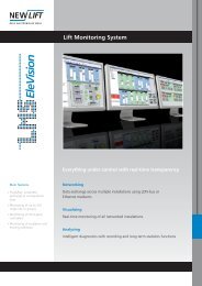
<strong>Lift</strong> <strong>Monitoring</strong> <strong>Software</strong><br />
Manual
Publisher NEW LIFT Steuerungsbau GmbH<br />
Lochhamer Schlag 8<br />
D-82166 Gräfelfing<br />
Phone: +49 (0) 89 / 89 866 - 0<br />
Fax: +49 (0) 89 / 89 866 - 300<br />
Doc. No. ELE_HB.EN11/01<br />
<strong>Software</strong> Version V1.1.2.1<br />
Date of issue 11/01<br />
Copyright © 2001, NEW LIFT Steuerungsbau GmbH<br />
All rights including those of copying and reproduction of parts of this<br />
description and of the translation are reserved by the publisher.<br />
No part of this description may be reproduced in any form or copied with an<br />
electronic replication system without the written permission of the<br />
publisher.<br />
ELE_HB.EN11/01
1 About this manual .............................................................................................. 5<br />
1.1 Signs and symbols used ......................................................................................... 5<br />
2 <strong>The</strong> <strong>ELEVISION</strong> <strong>Lift</strong> <strong>Monitoring</strong> <strong>Software</strong> ........................................... 7<br />
3 Installing and starting the program ........................................................ 9<br />
4 <strong>ELEVISION</strong> Project Management ............................................................ 11<br />
Creating a new project...................................................................................................... 11<br />
Project Manager ............................................................................................................... 12<br />
5 Program Modules ............................................................................................... 15<br />
5.1 Main Window ............................................................................................................. 15<br />
5.2 Campus Module ........................................................................................................ 19<br />
5.3 Group Module ............................................................................................................ 21<br />
5.4 Details Module ........................................................................................................... 23<br />
5.5 FST Panel Module .................................................................................................... 27<br />
5.6 Event Viewer Module .............................................................................................. 28<br />
5.7 Recording Module .................................................................................................... 30<br />
5.8 Special Functions Window.................................................................................. 31<br />
5.9 Statistics Module ...................................................................................................... 35<br />
5.10 Scheduler Module .................................................................................................... 37<br />
5.11 Settings Window...................................................................................................... 41<br />
5.12 About Window ........................................................................................................... 43<br />
Contents<br />
ELE_HB.EN11/01 3
Contents<br />
6 User Database and Rights ........................................................................... 45<br />
4 ELE_HB.EN11/01
1 About this manual<br />
1 About this manual<br />
This manual will give you a detailed overview of the <strong>ELEVISION</strong> <strong>Lift</strong><br />
<strong>Monitoring</strong> <strong>Software</strong>. <strong>The</strong> separate modules, functions and display levels<br />
of the software will be explained.<br />
This manual will help you during installation and use of the <strong>ELEVISION</strong> <strong>Lift</strong><br />
<strong>Monitoring</strong> <strong>Software</strong>. It contains important instructions on avoiding<br />
malfunctioning of <strong>ELEVISION</strong>.<br />
This document only describes the NEW LIFT assemblies and modules of<br />
<strong>ELEVISION</strong>.<br />
Please refer to the respective manufacturer’s or supplier’s documentation<br />
for information on components of the <strong>Lift</strong> <strong>Monitoring</strong> System not<br />
manufactured and delivered by NEW LIFT.<br />
� Signs and symbols used<br />
<strong>The</strong> following signs and symbols are used for activities and notes:<br />
Symbols � Activity Symbol:<br />
Activities described after this symbol must be carried out in the given<br />
order.<br />
Warning sign Note<br />
NOTE!<br />
<strong>The</strong> properties and functions of <strong>ELEVISION</strong> described in this manual<br />
can only be used to their full extent in combination with FST Control<br />
Systems manufactured by NEW LIFT Steuerungsbau GmbH.<br />
� Result symbol:<br />
<strong>The</strong> result of an activity is described.<br />
+ Key combination:<br />
Press the linked keys simultaneously.<br />
This sign marks instructions that must be followed with the<br />
<strong>ELEVISION</strong> <strong>Lift</strong> <strong>Monitoring</strong> <strong>Software</strong>.<br />
ELE_HB.EN11/01 5
1 About this manual<br />
6 ELE_HB.EN11/01
2 <strong>The</strong> <strong>ELEVISION</strong> <strong>Lift</strong> <strong>Monitoring</strong> <strong>Software</strong><br />
2 <strong>The</strong> <strong>ELEVISION</strong> <strong>Lift</strong> <strong>Monitoring</strong> <strong>Software</strong><br />
<strong>The</strong> <strong>ELEVISION</strong> <strong>Lift</strong> <strong>Monitoring</strong> <strong>Software</strong> is part of the LMS <strong>Lift</strong> <strong>Monitoring</strong><br />
System manufactured by NEW LIFT Steuerungsbau GmbH. It is a<br />
management software developed for monitoring and parametrising FST<br />
<strong>Lift</strong> Control Systems. Beyond that, <strong>ELEVISION</strong> provides a multitude of<br />
features and functions for data management and data processing.<br />
<strong>ELEVISION</strong> is a 32-bit PC software for Windows 9x, 2000 and NT designed<br />
with the latest development tools.<br />
System requirements To ensure troublefree operation of <strong>ELEVISION</strong>, the PC must meet the<br />
following requirements:<br />
Minimum Recommended<br />
Processor Pentium, 120 MHz Pentium II, 800 MHz<br />
Ports One free serial One free serial<br />
Operating system Windows 9x, NT (NT4 Windows 2000, NT (NT4<br />
with Service Pack 4!) with Service Pack 4!)<br />
Memory 32 MB RAM 128 MB RAM<br />
Video card 800 × 600 Pixel<br />
1024 × 768 Pixel<br />
with 256 colours with 256 colours<br />
Free disk space 10 MB 25 MB<br />
Program modules <strong>ELEVISION</strong> contains the following modules:<br />
Module Function<br />
<strong>Monitoring</strong> Real-time visualisation of all connected systems in<br />
various display levels.<br />
Error analysis Chronological archiving and analysis of error lists from<br />
the connected controls.<br />
Recording Transmission and evaluation of FST recordings.<br />
Statistics Creation of numerical and graphical statistics about<br />
runs, calls and errors.<br />
Remote control Triggering commands and parametrising using FST<br />
Remote Display.<br />
Editor Comfortable editing of FST parameter sets.<br />
ADM Config Editing parameters of landing button modules and<br />
position indicators using the LON bus.<br />
Scheduler Scheduling calendar-controlled actions.<br />
ELE_HB.EN11/01 7
2 <strong>The</strong> <strong>ELEVISION</strong> <strong>Lift</strong> <strong>Monitoring</strong> <strong>Software</strong><br />
Using the modules <strong>Monitoring</strong>, Error analysis, Recording, Statistics,<br />
Remote control and Scheduler is explained here.<br />
Please refer to the FST Editor Manual for further information on the<br />
modules Editor and ADM Config.<br />
8 ELE_HB.EN11/01
3 Installing and starting the program<br />
3 Installing and starting the program<br />
<strong>ELEVISION</strong> is a component of the LMS <strong>Lift</strong> <strong>Monitoring</strong> System and is<br />
delivered either on multiple floppy discs or on an installation CD.<br />
During the installation process <strong>ELEVISION</strong> is copied to the hard drive of<br />
the user's PC from where it can be started.<br />
<strong>The</strong> default installation folder of the program is<br />
c:\Programs\<strong>New</strong><strong>Lift</strong>\Elevision\<br />
During installation the user can select a different installation folder.<br />
Installation from floppy disc Proceed as follows to install <strong>ELEVISION</strong> from floppy discs:<br />
� Make sure the Windows operating system is running<br />
� Insert the first installation disc in drive a: of your PC<br />
� Start Windows Explorer and select drive a:<br />
� Start the installation program setup.exe and follow the instructions on<br />
the screen<br />
� ELEVSION is installed on your PC<br />
Installation from CD Proceed as follows to install <strong>ELEVISION</strong> from CD:<br />
� Make sure the Windows operating system is running<br />
� Insert the installation CD in the CD drive of your PC<br />
� Start Windows Explorer and select the CD-ROM-drive<br />
� Start the installation program setup.exe and follow the instructions on<br />
the screen<br />
� ELEVSION is installed on your PC<br />
<strong>The</strong> installation program has created a shortcut to <strong>ELEVISION</strong> on your<br />
desktop and the entry "NEW LIFT GmbH – <strong>ELEVISION</strong>" is added to the<br />
start menu of Windows.<br />
Quick start At the end of the installation process <strong>ELEVISION</strong> can be started by<br />
selecting the according option.<br />
Starting the program After successful installation <strong>ELEVISION</strong> can be started using the shortcut<br />
on your desktop or from the start menu of Windows.<br />
ELE_HB.EN11/01 9
3 Installing and starting the program<br />
NOTE!<br />
When starting the program for the first time no <strong>ELEVISION</strong> project is<br />
activated.<br />
� Create a new <strong>ELEVISION</strong> project by reading the control<br />
configuration of the connected systems (further information in<br />
“Creating a new project” on page 11).<br />
An existing <strong>ELEVISION</strong> project will be opened automatically when starting<br />
the program. If a modem connection is required for the project the<br />
connection will be established automatically.<br />
NOTE!<br />
When starting the program the last active <strong>ELEVISION</strong> project is opened<br />
automatically.<br />
� Make sure a direct serial connection or a modem connection to the<br />
lift systems is established before starting the program. Please refer<br />
to the description of the LMS System for information on the<br />
connection and cables required for your type of system.<br />
10 ELE_HB.EN11/01
4 <strong>ELEVISION</strong> Project Management<br />
Creating a new project<br />
4 <strong>ELEVISION</strong> Project Management<br />
<strong>ELEVISION</strong> has a project database for managing your projects. All data is<br />
saved in separate projects.<br />
A project includes:<br />
- Project name<br />
- Project description<br />
- Number and configuration of connected systems<br />
- Phone number for modem connection<br />
- Status, size and layout of the <strong>ELEVISION</strong> program windows<br />
(modules)<br />
- Error and event lists<br />
Managing this data in a project database eliminates the need for the user<br />
to read the control configuration required for graphical display of the<br />
systems over and over again. Furthermore, all required phone numbers,<br />
window settings as well as error and event lists are managed separately for<br />
each project.<br />
<strong>The</strong> Project Management is particularly important when using system<br />
type 1, where separate systems can be selected and monitored during an<br />
<strong>ELEVISION</strong> session. System types 2 and 3 with fixed hardware (Campus<br />
in the following) connected permanently to the LMS PC are mainly used for<br />
one project.<br />
Please refer to the description of the LMS System for further information on<br />
LMS system types.<br />
When starting <strong>ELEVISION</strong> for the first time or visualising a system or a<br />
Campus for the first time you must create a new project. You can do this<br />
using a special editing window that can be started from the main menu or<br />
the toolbar.<br />
NOTE!<br />
A serial connection to the connected systems must be established when<br />
creating a new project.<br />
� Make sure the serial connection required for you system type is<br />
established with the connected systems (see description of LMS<br />
System).<br />
ELE_HB.EN11/01 11
4 <strong>ELEVISION</strong> Project Management<br />
Project Manager<br />
Buttons<br />
Fig. 4.1 Creating a new project<br />
Enter the required data in the appropriate fields.<br />
Button Function<br />
Read and save the new project with the data entered<br />
Leave window without changes<br />
<strong>The</strong> <strong>ELEVISION</strong> Project Manager provides graphic access to the project<br />
management and gives you a simple and clear overview of all your<br />
systems.<br />
<strong>The</strong> Project Manager can be started from the main menu or the toolbar.<br />
Please refer to “Program Modules” on page 15 for further information.<br />
<strong>The</strong> list of saved projects can be displayed in two views: with project icons<br />
or in a list.<br />
12 ELE_HB.EN11/01
Fig. 4.2 Project Manager with icon view<br />
Fig. 4.3 Project Manager with list view<br />
4 <strong>ELEVISION</strong> Project Management<br />
ELE_HB.EN11/01 13
4 <strong>ELEVISION</strong> Project Management<br />
Buttons<br />
NOTE!<br />
Button Function<br />
Toggle Project Manager view<br />
Change description text of the selected project, see<br />
"Description" in list view<br />
Change name of the selected project<br />
Delete the selected project from project database<br />
Read and save system configuration of the selected<br />
project<br />
Open the selected project<br />
Leave Project Manager without changes<br />
When starting the program for the first time no <strong>ELEVISION</strong> project is in<br />
the Project Manager.<br />
� Close the Project Manager with "Cancel" and create a new<br />
<strong>ELEVISION</strong> project by reading the control configuration of the<br />
connected systems (further information in “Creating a new project”<br />
on page 11).<br />
14 ELE_HB.EN11/01
5 Program Modules<br />
5.1 Main Window<br />
Fig. 5.1 Main Window<br />
5 Program Modules<br />
5.1 Main Window<br />
<strong>The</strong> program modules and functions as well as the use of <strong>ELEVISION</strong> is<br />
presented here.<br />
<strong>The</strong> main window is one level above the modules and functions. It is<br />
opened automatically when starting the program. All modules and<br />
functions of <strong>ELEVISION</strong> are started from the main window.<br />
ELE_HB.EN11/01 15
5 Program Modules<br />
5.1 Main Window<br />
Main Menu and Toolbar <strong>The</strong>n main menu and the toolbar are located in the <strong>ELEVISION</strong> main<br />
window. <strong>The</strong>y provide comfortable access to all modules and functions.<br />
Fig. 5.2 Main Menu and Toolbar<br />
Functions<br />
Main Menu Toolbar Module or Function<br />
File<br />
- <strong>New</strong><br />
File<br />
- Open<br />
File<br />
- Exit<br />
View<br />
- Campus<br />
View<br />
- Monitor<br />
View<br />
- Detail<br />
View<br />
- Event Viewer<br />
View<br />
- FST-Keypad<br />
View<br />
- Recording<br />
View<br />
- FST Editor<br />
View<br />
- FST-Functions<br />
View<br />
- ADM-Config<br />
Create a new project using the editing<br />
window<br />
Open an existing project using the Project<br />
Manager<br />
- Quit <strong>ELEVISION</strong><br />
Open Campus Module<br />
Open Group Module<br />
Open Details Module<br />
Open Event Viewer Module<br />
Open FST Panel Module<br />
Open Recording Module<br />
Open Editor Module (included in Editor<br />
bundle, see Editor manual)<br />
Open window for entering special<br />
functions<br />
Open ADM-Config Module<br />
- Open Statistics Module<br />
- Open Scheduler Module<br />
Options<br />
- Tree View<br />
Options<br />
- Settings<br />
Options<br />
- User Dialog<br />
Windows<br />
- Cascade<br />
Toggle tree view on and off<br />
- Open settings window<br />
- Open window for user profiles<br />
cascade all active windows (modules)<br />
16 ELE_HB.EN11/01
Windows<br />
- Tile Horizontally<br />
Windows<br />
- Tile Vertically<br />
Windows<br />
- Minimize all<br />
Windows<br />
- Arrange all<br />
Windows<br />
- Display View 1<br />
Windows<br />
- Display View 2<br />
Windows<br />
- Store View 1<br />
Windows<br />
- Store View 2<br />
Help<br />
- About<br />
5 Program Modules<br />
5.1 Main Window<br />
Main Menu Toolbar Module or Function<br />
Tile all active windows (modules) on top of<br />
each other<br />
Tile all active windows (modules) next to<br />
each other<br />
- Minimize all active windows (modules)<br />
- Arrange all active windows (modules)<br />
Display window layout stored in View 1<br />
Display window layout stored in View 2<br />
- Save current window layout as<br />
View 1<br />
- Save current window layout as<br />
View 2<br />
- Program information window displaying<br />
the <strong>ELEVISION</strong> Version Number<br />
- Synchronize time of FST Controls with PC<br />
time.<br />
Tree View <strong>The</strong> tree view provides quick access to all systems of the campus.. <strong>The</strong><br />
systems can be identified with their system name. Double-clicking on a<br />
system opens the according Group or Details Module.<br />
Fig. 5.3 Tree View<br />
ELE_HB.EN11/01 17
5 Program Modules<br />
5.1 Main Window<br />
Status Bar <strong>The</strong> status bar contains the following information:<br />
Fig. 5.4 Status Bar<br />
Panel Information<br />
Current PC time<br />
Currently activated COM port<br />
18 ELE_HB.EN11/01
5.2 Campus Module<br />
5 Program Modules<br />
5.2 Campus Module<br />
<strong>The</strong> Campus Module provides the first display level of the real-time<br />
monitoring process (lowest resolution of display). It is only available with<br />
system types 2 and 3 and contains a top view of the entire campus.<br />
Double-clicking on one of the systems opens the Group or Details Module<br />
of that system.<br />
Fig. 5.5 Campus Module<br />
Area Function<br />
Top view of system A with floor position "5" highlighted in<br />
green means travel direction = UP.<br />
Top view of system A with floor position "5" highlighted in red<br />
means travel direction = DOWN.<br />
ELE_HB.EN11/01 19
5 Program Modules<br />
5.2 Campus Module<br />
Right mouse button <strong>The</strong> right mouse button opens a context menu in the Campus Module. With<br />
the context menu you can edit and configure the Campus Module.<br />
Menu item Function<br />
Edit Graphic positioning and measuring of the lift shafts in top view<br />
Options Changing the basic settings of the lift shafts in top view<br />
Campus Editor When opening the Campus Editor with the right mouse button you can<br />
position the lift shafts and change the size of the group fields using the<br />
mouse.<br />
By opening the context menu again with the right mouse button you can<br />
exit the Campus Editor.<br />
Fig. 5.6 Campus Editor<br />
NOTE!<br />
<strong>The</strong> Campus Editor is only available on the LMS Server when using the<br />
client-server option of system type 3.<br />
Options In the window for entering options you can also toggle the shaft names on<br />
and off and set the shaft size in pixels.<br />
20 ELE_HB.EN11/01
5.3 Group Module<br />
Fig. 5.7 Group Module<br />
5 Program Modules<br />
5.3 Group Module<br />
<strong>The</strong> Group Module provides the second display level of the real-time<br />
monitoring process (medium resolution of display). It contains a vertical<br />
model of the currently activated lift group.<br />
Remote control with landing and in-car calls is possible in the Group<br />
Module. A call can be started by clicking on the call with the right mouse<br />
button.<br />
Double-clicking on one of the lift shafts opens the Details Module of that<br />
system.<br />
ELE_HB.EN11/01 21
5 Program Modules<br />
5.3 Group Module<br />
Area Function<br />
FST A System name<br />
Position indicator and display for direction of travel<br />
Landing calls on door A (and on door B) can be activated by<br />
clicking with the mouse. <strong>The</strong> related call can be blocked by<br />
clicking on the call with the right mouse button.<br />
In-car calls on door A (and on door B) can be activated by<br />
clicking with the mouse. <strong>The</strong> related call can be blocked by<br />
clicking on the call with the right mouse button.<br />
Car with position of car doors on door A and B. <strong>The</strong> current<br />
direction of travel is indicated with a green arrow for up and a<br />
red arrow for down. A yellow frame around the car indicates<br />
approaching state, photocell and reversing switch are<br />
indicated with a yellow arrow.<br />
<strong>The</strong>re is no serial connection to this system or the system is<br />
switched off<br />
Current state of the safety circuit, the five LEDs indicate from<br />
left to right "Locking device", "Door A", "Door B", "Revolving<br />
door" und "Emergency stop"<br />
Current state of the FST Control and current speed of the<br />
drive, please refer to the FST manual for information on<br />
possible control states<br />
22 ELE_HB.EN11/01
5.4 Details Module<br />
Fig. 5.8 Details Module<br />
5 Program Modules<br />
5.4 Details Module<br />
<strong>The</strong> Details Module provides the third display level of the real-time<br />
monitoring process (highest resolution of display). It contains a vertical<br />
model of the currently activated lift system and detailed information on<br />
doors, drive, shaft positioning and error stack.<br />
Remote control with landing and in-car calls is possible in the Details<br />
Module. A call can be started by clicking on the call with the right mouse<br />
button.<br />
Double-clicking on the lift shaft opens the FST Panel Module of that<br />
system.<br />
<strong>The</strong> display of the vertical model with landing and in-car calls is identical<br />
with the display in the Group Module.<br />
ELE_HB.EN11/01 23
5 Program Modules<br />
5.4 Details Module<br />
Doors<br />
Car<br />
Positioning<br />
Area Function<br />
Status Current status of the car door<br />
Motor-Close Door close call is active<br />
Motor-Up Door open call is active<br />
Limitswitch-Closed Door limit switch close has triggered<br />
Limitswitch-Opened Door limit switch open has triggered<br />
Reversing Door is in reversing mode<br />
Photocell Photocell is interrupted<br />
Reversing switch Reversing switch is active<br />
Blocked Car door has been blocked from FST Menu<br />
<strong>The</strong> states listed here are valid for car door A and B.<br />
Area Function<br />
Load Sensor Displays the load of the car in percent (only displayed<br />
with analogue weighing devices)<br />
Weight State Displays the weight state of the car (e.g. overload, top<br />
load, empty load)<br />
Car Light Displays the state of the car light sensor on the car roof<br />
Min Wait Timer Displays if the set minimal wait time of the car on the<br />
current floor has elapsed<br />
Parking Displays if the car is parked<br />
Homing Displays if the car has been sent back do the lowest floor<br />
(hydraulic systems only)<br />
Group Member Displays if the system is member of a group<br />
In Group Displays if the system is currently running in group mode<br />
Area Function<br />
Position Current position of car measured in mm from levelling<br />
position of lowest floor<br />
Level Displays if the car is in the levelling zone<br />
Zone Displays if the car is in the door zone area<br />
Zone Enabled Displays if the FST Control has enabled the zone circuit<br />
Approaching Displays if the car is in approaching state<br />
24 ELE_HB.EN11/01
Service<br />
Drive<br />
Target<br />
Identification<br />
Safety Circuit<br />
Area Function<br />
5 Program Modules<br />
5.4 Details Module<br />
Service-Mode Displays if the Service Mode of the FST Control is<br />
activated (see FST manual)<br />
Service-due Displays if on of the set service counters for drives,<br />
motor hours or door cycles has exceeded its interval<br />
Motor hours Current value of operating hours counter<br />
Drive count Current value of run counter<br />
Door Cycles-A Current value of door cycle counter for car door A<br />
Door Cycles-B Current value of door cycle counter for car door B<br />
Area Function<br />
Motor State of the drive motor<br />
Drive Status Current status of the drive<br />
Velocity Current speed of car in mm/s<br />
Relevelling UP Displays if the car is in the relevelling zone "up" (is too<br />
low)<br />
Relevelling DOWN Displays if the car is in the relevelling zone "down" (is too<br />
high)<br />
Area Function<br />
Floor Next target floor of the car<br />
Target Dir. Direction of travel to next target floor<br />
Area Function<br />
<strong>Lift</strong> ID-Number Identification of the system in the lift group (A to H)<br />
<strong>Lift</strong> ID-Name Name or location of the system<br />
Order ID NEW LIFT factory number of the system<br />
Neuron ID Unique LON identification number of the FST Control<br />
Area Function<br />
TK State of locking switches (shaft doors)<br />
TA State of door contact for car door A<br />
TB State of door contact for car door B<br />
TC State of door contact for car door C (or revolving door<br />
switch)<br />
NH State of the emergency circuit<br />
ELE_HB.EN11/01 25
5 Program Modules<br />
5.4 Details Module<br />
Error Stack Button/Area Function<br />
Update error stack (synchronize with internal error<br />
storage of the FST)<br />
Date Date of the event<br />
Time Time of the event<br />
Floor Floor of the event<br />
Virtual Positioning<br />
Signals<br />
Additional coded event information (see FST manual)<br />
Real Positioning<br />
Signals<br />
Additional coded event information (see FST manual)<br />
Error Code ID of the event (see FST manual)<br />
Error Text Text description of the event<br />
Info Additional coded event information (see FST manual)<br />
26 ELE_HB.EN11/01
5.5 FST Panel Module<br />
5 Program Modules<br />
5.5 FST Panel Module<br />
<strong>The</strong> FST Panel Module provides the remote control functions of<br />
<strong>ELEVISION</strong>. It includes a copy of the FST user interface of the currently<br />
activated system with FST Display and FST Keyboard.<br />
<strong>The</strong> FST Panel Module provides all remote control functions and<br />
parametrising functions of the FST Control in a familiar environment. You<br />
can navigate through the FST Menu in the usual way by clicking on the<br />
buttons of the FST Keypad with the mouse.<br />
NOTE!<br />
Special function of the S key: <strong>The</strong> key combination S+ is made<br />
sequentially in the FST Panel Module.<br />
Please refer to the FST manual for information on the FST Display and on<br />
the navigation in the FST Menu.<br />
Fig. 5.9 FST Panel Module<br />
ELE_HB.EN11/01 27
5 Program Modules<br />
5.6 Event Viewer Module<br />
5.6 Event Viewer Module<br />
<strong>ELEVISION</strong> contains an event database with all FST events that are stored<br />
in the FST error stack in chronological order.<br />
<strong>The</strong> Event Viewer Module provides a detailed display of database entries<br />
as well as filter functions.<br />
Fig. 5.10 Event Viewer Module<br />
Button/Area Function<br />
Display error messages<br />
Display event messages<br />
Display LMS messages<br />
Update error stack (synchronize with internal error<br />
storage of the FST)<br />
Delete error stack (no undo!!!)<br />
Date/Time Date and time of the event<br />
Index Index of the event in the database (consecutively<br />
numbered)<br />
Code ID of the event (see FST manual)<br />
Floor Floor of the event<br />
Virt Additional coded event information (see FST<br />
manual)<br />
Real Additional coded event information (see FST<br />
manual)<br />
28 ELE_HB.EN11/01
5 Program Modules<br />
5.6 Event Viewer Module<br />
Button/Area Function<br />
Info Additional coded event information (see FST<br />
manual)<br />
Class Event class<br />
Messagetext Text description of the event<br />
Print event list on current system printer<br />
Print selected area only (currently highlighted<br />
events)<br />
ELE_HB.EN11/01 29
5 Program Modules<br />
5.7 Recording Module<br />
5.7 Recording Module<br />
With the Recording Module you can start, stop and save recordings of the<br />
currently activated FST Control from the LMS PC.<br />
With the additional FST VIEWER module you can analyse these<br />
recordings and convert them to graphical or numerical statistics.<br />
Fig. 5.11 Recording Module<br />
Button/Area Function<br />
Setting the recording filter:<br />
- Record drive curve<br />
- Record statistics<br />
- Record detailed information<br />
Start FST recording<br />
Stop FST recording<br />
List of all stored FST recordings<br />
Start drive recording viewer<br />
Create statistics for FST VIEWER<br />
Start text view of FST recording<br />
30 ELE_HB.EN11/01
5.8 Special Functions Window<br />
Fig. 5.12 Special Functions Window<br />
5 Program Modules<br />
5.8 Special Functions Window<br />
With the Special Functions Window you can define remote control<br />
functions (e.g. blocking doors) using the relating parameters. <strong>The</strong> defined<br />
functions can either be activated directly or you can enter them in the<br />
Scheduler.<br />
<strong>The</strong> Scheduler activates and deactivates the defined remote control<br />
functions.<br />
Group window In the group window you can select one of the connected systems for<br />
remote control.<br />
Select a system in the list displayed with the mouse.<br />
Depending on the requested remote control function only a complete group<br />
or a single FST in the group can be selected.<br />
ELE_HB.EN11/01 31
5 Program Modules<br />
5.8 Special Functions Window<br />
Fig. 5.13 Group window<br />
Floor window In the floor window the floors of the system selected in the group window<br />
are displayed graphically.<br />
Separate floors can be activated or deactivated (highlighted red) with the<br />
mouse.<br />
With the button "Set All" all floors can be activated. With the button "Delete<br />
All" all floors are deactivated.<br />
Fig. 5.14 Floor window<br />
Functions window <strong>The</strong> functions window provides all remote control functions and their<br />
function parameters. <strong>The</strong> functions are organized on separate tabs. <strong>The</strong>y<br />
are divided in the groups "FST-Functions", GST-Functions" and "Special<br />
Functions".<br />
<strong>The</strong> button "Start Direct" activates the selected function for the floors<br />
selected in the floor window and the system activated in the group window.<br />
<strong>The</strong> button "<strong>New</strong> Scheduler Entry" enters the selected function in the<br />
Scheduler. <strong>The</strong> Scheduler Module is opened automatically.<br />
32 ELE_HB.EN11/01
Fig. 5.15 Function window<br />
5 Program Modules<br />
5.8 Special Functions Window<br />
Function description <strong>The</strong> following table contains a short description of all remote control<br />
functions.<br />
All functions described here only apply to the system selected in the group<br />
window.<br />
FST-Functions<br />
Function Parameter Description<br />
Lock calls Landing calls Landing calls from the floor(s) selected in the floor window are<br />
blocked<br />
Car calls In-car calls from the floor(s) selected in the floor window are blocked<br />
Parkdrive - <strong>The</strong> floor selected in the floor window is set as parking floor<br />
<strong>Lift</strong> off Hard <strong>The</strong> system is shut down. <strong>The</strong> parameter "hard" deletes all pending<br />
in-car and landing calls.<br />
Landing control - All landing calls are blocked.<br />
Lock door Door A Car door A is locked and stays closed.<br />
Door B Car door B is locked and stays closed.<br />
Recording Get recording Transfer recording from the control to the PC<br />
Restart after Recording<br />
get<br />
Recording is restarted after data has been transferred<br />
Drive curve <strong>The</strong> drive curve is recorded<br />
Statistics Statistical events are recorded<br />
Detail Infos All control events are recorded in detail<br />
ELE_HB.EN11/01 33
5 Program Modules<br />
5.8 Special Functions Window<br />
Group-Functions<br />
Function Parameter Description<br />
Traffic-Programs Normal Mode Activates the group traffic program "Normal Mode"<br />
Up - Peak Activates the group traffic program "Up – Peak" for entering the<br />
building<br />
Down - Peak Activates the group traffic program "Down – Peak" for leaving the<br />
building<br />
Noon - Peak Activates the group traffic program "Noon – Peak"<br />
Group Special<br />
Functions<br />
- currently not available<br />
Please refer to the description of the GST System for further information on<br />
group traffic programs.<br />
Special Functions<br />
Function Parameter Description<br />
EAZ-Download EAZ Side A Upgrades the software of the position indicator on door side A<br />
EAZ Side B Upgrades the software of the position indicator on door side B<br />
NOTE!<br />
Special functions cannot be entered in the Scheduler.<br />
� Activate special functions with the button "Start Direct".<br />
� Only activate special functions after consulting the NEW LIFT<br />
Hotline.<br />
34 ELE_HB.EN11/01
5.9 Statistics Module<br />
Fig. 5.16 Statistics Module<br />
5 Program Modules<br />
5.9 Statistics Module<br />
<strong>The</strong> Statistics Module provides a graphical and numerical display of the<br />
internal FST statistics memory (long-term memory). <strong>The</strong> statistics memory<br />
can be transferred from the control to the PC where it can be evaluated.<br />
Long-term statistics of calls, drives, wait times, door cycles and system<br />
states can be displayed in different forms (bar diagrams).<br />
ELE_HB.EN11/01 35
5 Program Modules<br />
5.9 Statistics Module<br />
<strong>The</strong> following table contains a description of all components of the<br />
Statistics Module.<br />
Area Component Function<br />
Number Cold starts Number of on/off cycles of the control (cold starts)<br />
Homings Number of homing processes<br />
Floors travelled Number of floors the car has passed (distance covered)<br />
Motor starts Number of runs<br />
FST Transfer internal FST statistics memory to PC and display<br />
Delete currents statistics display on PC<br />
File Save the currently displayed statistics memory to the hard drive of the PC<br />
Open a statistics memory saved on the hard drive of the PC<br />
Print the currently displayed bar diagram<br />
<strong>The</strong> following bar diagrams are provided by the Statistics Module:<br />
Diagram Display Description Number of bars<br />
Car calls Floor Number of in-car calls by floor One bar per floor<br />
Time Number of in-car calls by time One bar per hour from<br />
midnight to midnight<br />
Landing calls Floor Number of landing calls by floor One bar per travel<br />
direction and floor<br />
Time Number of landing calls by time One bar per travel<br />
direction and floor from<br />
midnight to midnight<br />
Runs Floor Number of runs by floor One bar per floor<br />
Time Number of runs by time One bar per hour from<br />
midnight to midnight<br />
High resolution Number of runs by time One bar per 5 minutes<br />
from midnight to midnight<br />
Wait times Floors Mean wait time by floor One bar per travel<br />
direction and floor<br />
Door cycles Floors Number of door open cycles by floor One bar per floor<br />
System states Times Frequency of the different states in hours One bar per state<br />
Percent Frequency of the different states in percent One bar per state<br />
Counter Frequency of the different states as counter One bar per state<br />
36 ELE_HB.EN11/01
5.10 Scheduler Module<br />
Fig. 5.17 Scheduler Module<br />
5 Program Modules<br />
5.10 Scheduler Module<br />
<strong>The</strong> Scheduler Module provides a scheduler in form of a calendar where<br />
times for switching on and off remote control functions can be entered.<br />
<strong>The</strong> Scheduler activates and deactivates the entered remote control<br />
functions automatically.<br />
ELE_HB.EN11/01 37
5 Program Modules<br />
5.10 Scheduler Module<br />
Time window In the time window you can edit times for switching the remote control<br />
function selected in the function table on and off. You can also select the<br />
retry cycle for the function.<br />
Fig. 5.18 Time window<br />
Area Component Function<br />
Start Enter the start date by selecting it from the calendar.<br />
Enter start time<br />
Stop Enter the stop date by selecting it from the calendar.<br />
Enter stop time<br />
38 ELE_HB.EN11/01
Area Component Function<br />
Retry No retry<br />
Daily<br />
Weekly<br />
Number of days / weeks of the retry cycle<br />
5 Program Modules<br />
5.10 Scheduler Module<br />
Activate Activate the times for switching on/off and the retry cycle in the function<br />
table.<br />
Function table <strong>The</strong> function table provides a list of all remote control functions and their<br />
status entered in the Scheduler.<br />
You can select and edit (e.g. start time) remote control functions in the<br />
function table.<br />
Fig. 5.19 Function table<br />
ELE_HB.EN11/01 39
5 Program Modules<br />
5.10 Scheduler Module<br />
Area Component Function<br />
Columns Start Displays the start time<br />
Stop Displays the stop time<br />
Action Short description of the remote control function<br />
Status Status of the remote control function<br />
- INACTIVE: Function is not enabled in the Scheduler<br />
- WAITING: Function is enabled in the Scheduler and is waiting for its start time<br />
- ACTIVE: Function is enabled in the Scheduler and is active<br />
- DELAYED: Function is active but can currently not be executed (due to other<br />
functions), waiting until it can be activated<br />
- EXECUTED: Function without retry has been executed successfully<br />
Buttons Enable the remote control function selected in the function table in the Scheduler<br />
Edit function parameters of the remote control function selected in the function<br />
table. <strong>The</strong> Special Functions Window is displayed.<br />
Delete the remote control function selected in the function table from the<br />
Scheduler<br />
Enter a new remote control function in the function table. <strong>The</strong> Special Functions<br />
Window is displayed.<br />
NOTE!<br />
<strong>The</strong> time functions of the Scheduler are controlled by the PC clock.<br />
� For proper use of the Scheduler the <strong>ELEVISION</strong> PC must have a<br />
permanent serial connection to the connected systems.<br />
� This means that proper use of the Scheduler with system type 1 is<br />
only possible with a direct serial connection.<br />
NOTE!<br />
<strong>The</strong> time functions of the Scheduler are stored in the project database.<br />
<strong>The</strong>y are not lost when restarting the program.<br />
� Delete unwanted time functions from the function table of the<br />
Scheduler.<br />
40 ELE_HB.EN11/01
5.11 Settings Window<br />
5 Program Modules<br />
5.11 Settings Window<br />
<strong>The</strong> Settings Window provides two basic <strong>ELEVISION</strong> settings.<br />
You can select if the last project should be opened automatically when<br />
starting the program. And you can switch the current project to modem<br />
operation.<br />
Fig. 5.20 Settings Window<br />
Area Component Function<br />
General Reopen last project during<br />
EleVision Startup<br />
You can select if the last project should be opened automatically<br />
when starting the program<br />
PC COM-Port Select the serial port of the PC for connecting to the controls<br />
Language Language Language of <strong>ELEVISION</strong>. When changing the language an<br />
additional language module available from NEW LIFT is required.<br />
Modem Use Modem Defines if a modem is to be used for serial data transmission with<br />
system type 1 (see description of the LMS System)<br />
Modem-Initstring 1 First initialisation string of the modem (pre-set)<br />
Modem-Initstring 2 Second initialisation string of the modem (pre-set)<br />
Dial String Phone number of the remote site<br />
Save settings and close window<br />
Leave window without changes<br />
ELE_HB.EN11/01 41
5 Program Modules<br />
5.11 Settings Window<br />
NOTE!<br />
For projects with modem operation activated an additional button is<br />
displayed in the toolbar.<br />
� With the additional button you can establish or deactivate the<br />
modem connection (see following table)<br />
Button Function<br />
Deactivate connection<br />
Establish connection<br />
42 ELE_HB.EN11/01
5.12 About Window<br />
5 Program Modules<br />
5.12 About Window<br />
In the about window you can find the version number of <strong>ELEVISION</strong>.<br />
Fig. 5.21 About Window<br />
NOTE!<br />
Technical questions can only be answered by the NEW LIFT Hotline<br />
with the ELEVSION version number.<br />
� Open the about window and note the<br />
<strong>ELEVISION</strong> version number (e.g. 1.1.2.1 Nov 13 2001).<br />
ELE_HB.EN11/01 43
5 Program Modules<br />
5.12 About Window<br />
44 ELE_HB.EN11/01
6 User Database and Rights<br />
Main Menu and Toolbar<br />
6 User Database and Rights<br />
With system type 3 (LMS client-server option) <strong>ELEVISION</strong> provides a user<br />
database. <strong>The</strong> user database prevents unauthorized access to the<br />
systems.<br />
All users that want to log in on the master PC with a LMS Client must have<br />
a user name and password for identification in the login window. If the<br />
name and password entered are stored in the user database the user is<br />
granted access to <strong>ELEVISION</strong> with his/her user rights.<br />
Fig. 6.1 Log in window<br />
Button/Area Function<br />
Login name User name given to the user<br />
Password Password for that user name<br />
Verify user name/password and <strong>ELEVISION</strong> login<br />
Logout and exit <strong>ELEVISION</strong><br />
Close and reopen login window<br />
Exit <strong>ELEVISION</strong> without login<br />
Creating a new user For all users of <strong>ELEVISION</strong> Clients an account must be created in the user<br />
database before their first login.<br />
You can create a new user profile in the user profile window.<br />
ELE_HB.EN11/01 45
6 User Database and Rights<br />
NOTE!<br />
Creating LMS users and editing user profiles can only be done on the<br />
master PC. User data cannot be accessed from the LMS Clients.<br />
Fig. 6.2 User profile window<br />
Button/Area Function<br />
User name User name given to the LMS Client<br />
Password Password for that user name<br />
Block list PAM List of PAM Addresses that are excepted from the<br />
Addresses<br />
rights management (no remote control possible for<br />
these FST Controls)<br />
Send calls Defines if the user can make use of the remote control<br />
functions for in-car and landing calls<br />
Trigger functions Defines if the user can trigger functions (task specific<br />
special functions)<br />
FST-Keypad Defines if the user can make use of the remote control<br />
functions of the FST Panel Module<br />
Campus Edit Defines if the user can change the layout of the<br />
systems in the Campus Module<br />
ADMIN No function at present<br />
Scroll forward/backward in the user database<br />
Add a new user<br />
Delete user from database<br />
Enter user data in database<br />
Leave window without changes<br />
46 ELE_HB.EN11/01
6 User Database and Rights<br />
Your NEW LIFT Hotline: e-mail: hotline@newlift.de<br />
Lochhamer Schlag 8 Phone: +49 (0) 89 / 89 866 - 0<br />
D-82166 Gräfelfing Fax: +49 (0) 89 / 89 866 - 300<br />
ELE_HB.EN11/01 47