
Create successful ePaper yourself
Turn your PDF publications into a flip-book with our unique Google optimized e-Paper software.
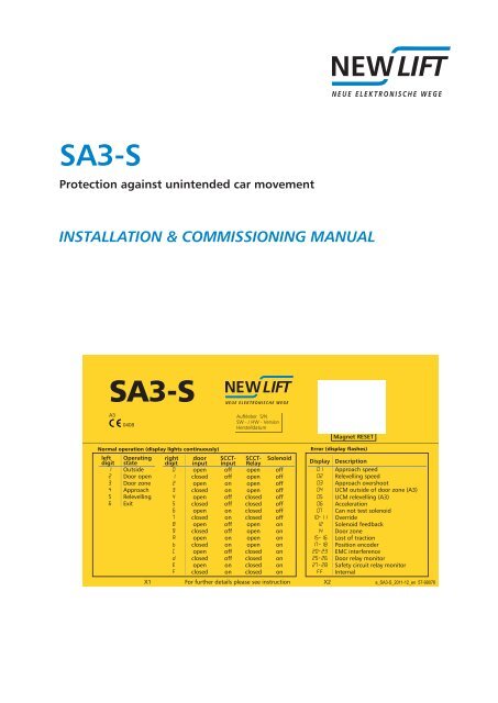
<strong>SA3</strong>-S<br />
Protectionagainstunintendedcarmovement<br />
INSTALLATION & COMMISSIONING MANUAL<br />
<strong>SA3</strong>-S<br />
A3<br />
0408<br />
Aufkleber S/N<br />
SW - / HW - Version<br />
Herstelldatum<br />
MagnetRESET<br />
left<br />
digit<br />
Operating<br />
state<br />
right<br />
digit<br />
door<br />
input<br />
SCCTinput<br />
SCCT-<br />
Relay Display Description<br />
1 Outside<br />
01 Approachspeed<br />
2 Dooropen<br />
02 Relevellingspeed<br />
3 Doorzone<br />
03 Approachovershoot<br />
4 Approach<br />
04 UCMoutsideofdoorzone(A3)<br />
5 Relevelling<br />
05 UCMrelevelling(A3)<br />
6 Exit<br />
06 Acceleration<br />
07 Cannottestsolenoid<br />
10-11 Override<br />
12 Solenoidfeedback<br />
14 Doorzone<br />
15-16 Lostoftraction<br />
17-18 Positionencoder<br />
20-23 EMCinterference<br />
25-26 Doorrelaymonitor<br />
27-28 Safetycircuitrelaymonitor<br />
FF Internal<br />
X1 Forfurtherdetailspleaseseeinstruction X2<br />
a_<strong>SA3</strong>-S_2011-12_en 57-99076<br />
Solenoid<br />
Normal operation (display lights continuously) Error (display flashes)<br />
0 open off open off<br />
1 closed off open off<br />
2 open on open off<br />
3 closed on open off<br />
4 open off closed off<br />
5 closed off closed off<br />
6 open on closed off<br />
7 closed on closed off<br />
8 open off open on<br />
9 closed off open on<br />
A open on open on<br />
b closed on open on<br />
C open off closed on<br />
d closed off closed on<br />
E open on closed on<br />
F closed on closed on
<br />
<br />
Manufacturer NEWLIFTSteuerungsbauGmbH<br />
LochhamerSchlag8<br />
82166Gräfelfing<br />
Phone+49 89 – 898 66 – 0<br />
Fax +49 89 – 898 66 – 300<br />
Mail info@newlift.de<br />
www.newlift.de<br />
Serviceline Phone+49 89 – 898 66 – 110<br />
E-mailservice@newlift.de<br />
Dateofissue 05.11.2012<br />
Author BP<br />
Release BP11/2012<br />
Hardwareversion V1.31/V1.32<br />
Doc.No. mia_<strong>SA3</strong>S_en<br />
Copyright ©NEWLIFTSteuerungsbauGmbH,2012.<br />
Thismanualisprotectedbycopyright.Allrights,includingthoseofcopying,of<br />
reproduction,oftranslationandofmodification,inwholeorinpart,arereservedby<br />
thepublisher.<br />
Nopartofthisdescriptionmaybereproducedinanyformorcopiedwithan<br />
electronicreplicationsystemwithoutwrittenpermission.<br />
Althoughgreatcarehasbeentakenintheproductionoftextsandfigures,we<br />
cannotbeheldlegallyliableforpossiblemistakesandtheirconsequences.<br />
<strong>SA3</strong>-SInstallation&CommissioningManual
Contents<br />
1 Aboutthismanual 1<br />
1.1 General 1<br />
1.2 Abbreviationsandsymbolsused 1<br />
2 Generalsafetyregulations 2<br />
2.1 Qualificationsoftheinstallingengineer 2<br />
2.2 Residualdangers 2<br />
2.3 Safetyregulations 3<br />
3 Technicaldata 5<br />
4 Planningthesystem 6<br />
5 Interfaces 8<br />
5.1 Connectiontothecontrolsystem 9<br />
5.2 Connectiontothesafetycircuit 10<br />
5.3 Display 11<br />
5.4 RemoteDisplayModule 13<br />
5.4.1 UserInterfaces 13<br />
6 Installation 14<br />
7 Commissioning 15<br />
7.1 RemoteDisplayModule 15<br />
8 Behaviourincaseoferrors 16<br />
9 Functiontestduringcommissioning 17<br />
10 Inspectionduringcommissioning 21<br />
11 Annualinspection 24<br />
12 Wastedisposal 25<br />
13 Appendix 26<br />
13.1 Releaseoftrappedpersons 26<br />
13.2 Calculatingthestoppingdistance 26<br />
13.2.1 Downwardstoppingdistance 26<br />
13.2.2 Upwardstoppingdistance 27<br />
14 Notice 29<br />
<strong>SA3</strong>-SInstallation&CommissioningManual I<br />
<br />
<br />
II <strong>SA3</strong>-SInstallation&CommissioningManual
1 Aboutthismanual<br />
Aboutthismanual<br />
The <strong>SA3</strong>-S safety device was developed to satisfy the "protection against unintended car movement" stipulated<br />
in the standard (EN 81-1:1998+A3:2009, 9.11).<br />
Read these instructions carefully before installing and commissioning the safety device. In addition, chapter „2<br />
General safety regulations“.<br />
Objectives of this manual:<br />
› Provision of the technical data<br />
› Installation and commissioning instructions<br />
› Maintenance instructions<br />
› Test instructions<br />
› Operation of the device.<br />
1.1 General<br />
This manual is intended to simplify installation and commissioning of the safety device. In addition, this manual<br />
also serves as a reference for the operator.<br />
It describes the commissioning, installation and maintenance procedures for a lift in connection with the <strong>SA3</strong>-S<br />
safety device for the "protection against unintended car movement".<br />
It contains important information for safe and proper installation and commissioning of the safety device.<br />
Following these instructions will help to:<br />
› prevent danger,<br />
› avoid repair costs and downtime,<br />
› increase the reliability and lifespan of the control system and of the lift system.<br />
Local, national and on-site regulations regarding health and safety and protection of the environment must be<br />
taken into account in addition to this installation and commissioning manual.<br />
This manual only describes the assemblies of the lift system delivered by NEW LIFT. For information about<br />
components of the lift system that were not manufactured and supplied by NEW LIFT, please refer to the respective<br />
user information supplied by the manufacturer or supplier.<br />
1.2 Abbreviationsandsymbolsused<br />
The following signs and symbols are used for operational instructions:<br />
Abbreviation Description<br />
SCCT Safetycircuit<br />
PE ProtectiveEarth;earthwire<br />
GND Ground;referencepotentialforsignalandoperatingvoltages<br />
AC Alternatingcurrent<br />
DC Directcurrent<br />
GB Overspeedgovernor<br />
Safety-relevant information<br />
This symbol is located in front of safety-relevant information.<br />
Information notice<br />
This symbol is located in front of relevant information.<br />
<strong>SA3</strong>-SInstallation&CommissioningManual 1
Generalsafetyregulations<br />
2 Generalsafetyregulations<br />
All important safety regulations are summarised in this chapter. These safety instructions must always be adhered<br />
to during all work on the installation.<br />
All persons performing installation and commissioning work on the <strong>SA3</strong>-S safety device must read this chapter<br />
and follow its regulations.<br />
Laws, regulations, guidelines and standards that apply in the country of operation must be followed in addition<br />
to the safety regulations mentioned in this manual.<br />
2.1 Qualificationsoftheinstallingengineer<br />
The installing engineer must:<br />
› be over 18 years of age (exception: apprentices who are over 16 years of age and are permanently supervised<br />
by an engineer qualified for training apprentices).<br />
› have first aid training,<br />
› have theoretical and practical knowledge of regulations and measures for the prevention of fire and explosions<br />
in his work area,<br />
› be able to identify, avoid and rectify all dangers that might occur during his work in the shaft and in the operating<br />
rooms,<br />
› be able to identify and rectify all irregularities and faults that might occur during installation and operation of a lift<br />
system,<br />
› have theoretical and practical knowledge of operating principles and requirements of electric controls and drive<br />
systems.<br />
All installation and commissioning work on electric and electronic components of the safety device must be<br />
performed by or supervised by a qualified electrician.<br />
A qualified electrician has appropriate training and knowledge of regulations that allow him to judge the quality<br />
of the work performed and identify possible dangers (BGV A3).<br />
2.2 Residualdangers<br />
Danger for persons<br />
The following shall always apply during all work on the installation:<br />
Danger to life! Do not touch live parts while working on electrical equipment.<br />
› Before starting work, make sure the system is off circuit.<br />
› Only carry out any installation work on electrical components when these are switched off and in an unpowered<br />
state.<br />
› Only use insulated tools when working on electrical system components.<br />
› Pay attention to the accident prevention regulations.<br />
Electrical hazard, leaking gas or water due to pierced supply lines. Risk of serious injury or death.<br />
› Make sure no supply lines are in the installation location before starting any installation work.<br />
› Danger of falling! Installing engineers and unauthorised persons can fall down the shaft. Risk of serious injury or<br />
death.<br />
› Block the shaft access points.<br />
› Use suitable protection (e.g. safety harnesses, scaffoldings) when working on or in the shaft.<br />
Danger of crushing due to intentional or accidental car movement. Risk of serious injury or death.<br />
› Block the shaft access points.<br />
› Before starting any work, make sure that there are no persons in the shaft or in the vicinity of moving parts of<br />
the drive.<br />
› Prevent unauthorised operation of the control system.<br />
2 <strong>SA3</strong>-SInstallation&CommissioningManual
Risk of material damage<br />
The following shall always apply during all work on the installation:<br />
Electrostatic charging<br />
› Keep the electronic assembly in its original packaging until installation.<br />
Generalsafetyregulations<br />
› Before opening the original packaging, a static discharge must be performed. To do this, touch a grounded<br />
piece of metal.<br />
› During work on electronic assemblies, periodically perform this discharge procedure.<br />
Electronic assemblies are destroyed by defective, interchanged or incorrectly mounted connectors, short-circuiting<br />
or excess voltage.<br />
› Check plugs for mechanical damage.<br />
› Never change pre-assembled connectors or cables.<br />
› Only connect loose or torn off wires according to circuit diagram details if this is possible on site (suitable material<br />
and tools must be available).<br />
› Pay attention to coding pins and latch lugs.<br />
2.3 Safetyregulations<br />
General<br />
› The instructions of the lift manufacturer and the instructions in this manual must be followed during installation<br />
and commissioning of the safety device.<br />
› The shaft must be secured against unauthorised trespassing during installation, commissioning, inspection and<br />
maintenance.<br />
› Assemblies, devices and cables must be installed and fastened securely and permanently.<br />
› Loads must be moved with suitable aids (lift trucks, hoisting gear etc.).<br />
› Sharp and pointed tools or other potentially dangerous objects may only be carried along in clothing if suitable<br />
protective measures have been taken to rule out any danger.<br />
› Alcohol and drugs must not be consumed before and during installation and commissioning.<br />
Documentation<br />
› A copy of the installation and commissioning manual must be available to the installing engineer at the time of<br />
installing and commissioning.<br />
› A copy of the installation and commissioning manual and the wiring diagrams must be kept in the control cabinet<br />
at all times after installation.<br />
› The wiring diagrams supplied with the <strong>SA3</strong>-S safety device are binding. Changes must only be made after consulting<br />
NEW LIFT and must be documented in writing on the system.<br />
› The factory-side inspection records of the <strong>SA3</strong>-S safety device remain with the manufacturer.<br />
Electricity<br />
› Regulations for installing and operating electrical equipment (VDE 0100) and regulations of local utilities must<br />
be followed.<br />
› The specified distances between different electrical assemblies must be controlled and maintained.<br />
› All installation work must be carried out with the system shut down and off circuit.<br />
› All cables and wires must be installed with sufficient strain relief.<br />
› The neutral and ground wires must be routed separately.<br />
<strong>SA3</strong>-SInstallation&CommissioningManual 3
Generalsafetyregulations<br />
Working in the shaft<br />
› Any work in the shaft requires perfect and permanent communication between the supervisor on the lift controller<br />
and the workers in the shaft.<br />
› Components in the shaft must be arranged or secured in such a way that persons accessing the shaft for inspection,<br />
maintenance or repair purposes are not in danger.<br />
› The maximum load of the lift system must not be exceeded.<br />
› The specified overruns of the emergency end switches in relation to the speed must be observed.<br />
› The emergency installations must not be activated during normal operation.<br />
› All emergency installations and braking systems must be checked for trouble-free operation and all shaft entrances<br />
closed off before beginning work.<br />
› Installation and operation are prohibited if other persons could be in danger.<br />
› Workers must be secured against falling.<br />
› In case of any work interruptions, the car must be moved to the lowest stop position, the control system switched<br />
off and the power supply (e.g. UPS) permanently disconnected.<br />
Personal safety equipment of the installing engineer<br />
› Eye protection<br />
› Safety boots<br />
› Protective helmet<br />
› Safety harness<br />
› Clothing suitable to the ambient conditions of the installation location<br />
› Jewellery, watches and similar items may not be worn; a hair net must be used if applicable.<br />
Handling electronic assemblies<br />
› Leave electronic assemblies in their original packaging until installation.<br />
› Touch a grounded piece of metal prior to opening the original packaging to prevent damage from static charges.<br />
Waste disposal<br />
› All packaging material must be disposed of in an environmentally acceptable manner; paper, plastic, metal,<br />
electronic assemblies etc. must be recycled.<br />
4 <strong>SA3</strong>-SInstallation&CommissioningManual
3 Technicaldata<br />
Technicaldata<br />
Parameters Min. Type Max.<br />
Operating voltage 1 24V DC<br />
Power consumption with energised solenoid 1A<br />
Power consumption with deenergised solenoid 0.3A<br />
Temperature: operation 0°C 65°C<br />
Temperature: storage & transport -20°C 70°C<br />
Relative humidity: operation (non-condensing) 15% 85%<br />
Relative humidity: storage & transport (non-condensing) 5% 95%<br />
Cable length to overspeed governor 2 100m<br />
Cable length to control system 2 100m<br />
Error-signal output current 0.7A<br />
Protection type IP64<br />
Possible safety circuit voltages 3 230V/50Hz, 110V/50Hz,<br />
24VDC - 150VDC<br />
Safeguarding of the safety circuit (external) 4A<br />
Position resolution (pulse interval) with HJ200 0.94mm<br />
Position resolution (pulse interval) with HJ250 0.94mm<br />
Position resolution (pulse interval) with HJ300 0.92mm<br />
Reaction time "A3" until solenoid has deenergised 82 ms<br />
Service life 20 years<br />
Table 1: Technical data<br />
1 The operating voltage must also remain active during a power failure of the main supply (see chapter "Planning the<br />
system").<br />
2 The maximum possible cable length to the overspeed governor and to the control system is heavily dependent on the<br />
distance of the cable to other sources of interference.<br />
3 Possible safety circuit voltages:<br />
The required voltage must be specified when ordering<br />
<strong>SA3</strong>-SInstallation&CommissioningManual 5
Planningthesystem<br />
4 Planningthesystem<br />
In order to use the <strong>SA3</strong>-S safety system together with a lift system, the following requirements must be satisfied:<br />
1. The lift control system must make available a signal that always becomes inactive when the car<br />
is not to be moved ("in motion" signal). This signal must be inactive on each stop. Level: 0V (car is<br />
moving) / 24V or high impedance (car is not moving). The signal is needed in order to test the solenoids<br />
at the overspeed governor and to allow that the magnetic coil drops with closed doors (quiescent state<br />
of the lift).<br />
2. The product must be supplied with power via a 24Vemergencypowerdevice.<br />
Reason: If power fails during travel, the solenoids must remain energised until the car stops, as the<br />
safety gear will otherwise be actuated. This delay is taken into account in the device, but can only take<br />
effect if the power supply is ensured for several seconds following power failure. Required is 24V/1A<br />
for about 10 sec. In addition, an UPS is needed in order to energise the solenoid during an emergency<br />
rescue so that the car can be moved. The emergency power supply must be designed accordingly.<br />
3. An override input ensures that the car can also be moved in the event of a power failure so that persons<br />
can be freed.<br />
In the override state, the solenoid energises and the safety circuit relay opens. Level: 0V (override) /<br />
high impedance (normal operation). For override, a separate switch must be wired in the control cabinet.<br />
It is to be labelled with "Ovrd. <strong>SA3</strong>-S".<br />
4. The safety gear that is to be used in combination with the <strong>SA3</strong>-S must satisfy the requirements of EN<br />
81-1:1998 + A3:2009 or EN81-2:1998 + A3:2009<br />
5. The car apron must satisfy the requirements of EN 81-1:1998 + A3:2009 point 8.4.<br />
An apron acc. to EN 81-21 is permissible only if the car apron satisfies the requirements specified in<br />
EN 81-1, section 8.4 over the entire shaft upon leaving the lowest floor. If this cannot be ensured, the<br />
calculation of the permissible upward stopping distance (see chapter "Upward stopping distance") can<br />
only take into account the vertical part of the car below the car threshold for the apron length.<br />
6. A formula must be used to theoretically verify that the car achieves the stopping distance specified in<br />
the standard. The "upward" and "downward" cases are to be calculated separately. The following data<br />
are necessary for this purpose:<br />
› Maximum length of the door zones in the up and down directions (normally 200mm in both<br />
directions)<br />
› Maximum reaction path of safety gear and overspeed governor (the path of the car from the<br />
time the safety cable is blocked until the safety gear reaches its guaranteed braking deceleration)<br />
in both directions<br />
› Minimum braking deceleration of the safety gear in both directions<br />
› Internal passage height to the car interior (for calculating the maximum downward stopping<br />
distance)<br />
› Length of the apron below the car (for calculating the maximum upward stopping distance)<br />
› Mass of empty car, cable and counterweight (for calculating the maximum possible upward<br />
acceleration)<br />
The product may only be used if the required stopping distances can be achieved. For some parameters,<br />
standard values may be used.<br />
7. The safety circuit of the lift system must be modified according to the specifications. In the standard<br />
device, the safety circuit voltage is 230V / 50Hz. Other voltages are possible on request.<br />
8. The PowerGood input signals a power failure at the control system. Level: 24V: current present / 0V or<br />
high impedance: power failure. Ideally, this input is supplied by the power supply of the control system.<br />
9. If the system is equipped with the "approach with open doors" function, the two door zone signals<br />
must be wired. These signals must also be monitored by an external safety circuit bypass control. Level:<br />
24V (door zone) / 0V or high impedance (outside of the door zone).<br />
10. To reset the product in the A3 case or after an error, a button ("reset") can be wired in the control<br />
cabinet. Level: 24V (reset) / 0V or high impedance (normal operation). The button is to be labelled with<br />
"Reset <strong>SA3</strong>-S". Alternatively, the <strong>SA3</strong>-S safety device can be reset with the aid of a magnet below the<br />
display.<br />
11. The "error" output of the product can be wired with an error lamp (24V, max. 0.7mA) or with the control<br />
system. This output is for information only and is not a safety function. The error lamp is not necessary if<br />
the device display can be viewed.If the error output is read by the controller, the controller must not stop<br />
the system in case of an error.<br />
6 <strong>SA3</strong>-SInstallation&CommissioningManual
12. Reset button and error display can be replaced by a "display module" in the control cabinet.<br />
Planningthesystem<br />
13. Position: <strong>SA3</strong>-S generates a two-channel incremental output which can be used as a position input for<br />
the control system. The resolution of the output is better than 1mm. Level: differential driver stage (2x<br />
two-wire)<br />
14. For the purpose of the arrest test, a button (N.C.) can be connected in the power supply of the device<br />
(connection B-3). Upon actuation of the button, the solenoid on the overspeed governor deenergises<br />
and the safety gear is triggered.<br />
15. The <strong>SA3</strong>-S safety system can be installed in hydraulic lifts. If a double-acting safety gear is used here,<br />
the same premises apply as to rope lifts. If only one safety gear should be used in the downwards direction,<br />
the following requirements must be met:<br />
› Safety gear in the downwards direction must conform to the requirements of EN81-2:1998 +<br />
A3:2009.<br />
› According to EN 81 the speed restrictor must also have force guided safety switches which<br />
opens the safety circuit in upward direction during magnet releasing.<br />
› Voltage of safety circuit must act directly on the braking element (e. g. motor contactor), i. e. by<br />
opening the safety circuit the car must come to a standstill through gravitational force.<br />
16. In case of hydraulic lifts the safety gear should not get jammed, during the car with the releasing solenoid<br />
coil is sinking slowly. For that prupose, the controller might activate the signal „in motion“for a short<br />
time.<br />
17. The <strong>SA3</strong>-S safety device has electronic inputs. In order to avoid disturbances of the system, carry out<br />
suitable interference suppression measures. These include:<br />
› Suppression circuits of all inductors (contactor, relay, brake systems…)<br />
› Suitable line filter for disruption of safety circuit from motor control<br />
› Suitable shielding of the cables to the motor and to the the inverter etc.<br />
› As possible a separate laying of the disturbing cable lines<br />
<strong>SA3</strong>-SInstallation&CommissioningManual 7
Interfaces<br />
5 Interfaces<br />
5.1 Circuitvariants<br />
There are 3 valid circuit variants for the <strong>SA3</strong>-S safety system. The following information applies to all variants:<br />
› In case there is no door bypass in the system, the two door zone inputs are not required, they are left open. The<br />
rest of the circuit will remain consistently. It is advisable to use in this case variant 2<br />
› Both GND potentials (from the power supply 24V and 24V emergency power supply) can be connected together<br />
externally.<br />
› If the system has the auxiliary control, the safety circuit relay can be placed in the safety circuit, where it is<br />
bypassed by the auxiliary control. Safety circuit relay can be located at any position in the safety circuit, e.g.<br />
also in front of the door contacts.<br />
Attention! During simultaneous use of override and auxiliary control make sure that all shaft and car doors are<br />
closed.<br />
8 <strong>SA3</strong>-SInstallation&CommissioningManual
5.1.1 Ageneralvariant<br />
The general variant can be used for all types of installations.<br />
N<br />
Variante 1:<br />
Sicherheitskreis/<br />
safety circuit<br />
Hängekabel/<br />
trailing cable<br />
Netzteil/<br />
power supply<br />
24V<br />
Türzone/<br />
door zone<br />
GND<br />
Türzone B/door zone B<br />
Türzone A/door zone A<br />
Aufzugsteuerung/<br />
lift control<br />
Türumgehung/door overbridge<br />
(Sicherheitsschaltung/<br />
safety circuit)<br />
B A<br />
Fahrkorbtüren/<br />
cabin door<br />
Position<br />
InFahrt/<br />
moving<br />
A-3 A-8 A-7 A-1 A-5 A-2 B-4 B-8 B-3 A-4 B-7<br />
B-1,B-2<br />
B-5,B-6<br />
A-6<br />
Sperrmittel/<br />
shaft doors<br />
Figure 1: Overview of the complete system (variant 1)<br />
Tür-Relais/<br />
door relais<br />
Externes Display/<br />
external display<br />
<strong>SA3</strong>-S<br />
N-Leiter/neutral<br />
SHK-Relais/<br />
safety circuit relais<br />
C-2 C-1 C-3 C-6 D-1 D-3 D-5 D-2<br />
Sicherheitskreis/<br />
safety circuit<br />
Notstromversorgung/<br />
backup supply<br />
Interfaces<br />
Geschwindigkeitsbegrenzer/<br />
overspeed<br />
governor<br />
Motorschütze/<br />
motor<br />
contactor<br />
<strong>SA3</strong>-SInstallation&CommissioningManual 9<br />
24V<br />
GND<br />
S/N: 250 8/11<br />
HW: VX.XX (230V/50Hz)<br />
SW: XXXXXXXX<br />
TÜV-A-AT-1/11/256CEES/X<br />
Auftrennung des Sicherheitskreises<br />
disruption of safety circuit
Interfaces<br />
5.1.2 Thesystemwithoutdoorbypass<br />
If the system does not have a door bypass, the door input (C6) is connected behind the last door in the safety<br />
circuit.The door relay has no function in this case.<br />
N<br />
Variante 2:<br />
Sicherheitskreis/<br />
safety circuit<br />
Hängekabel/<br />
trailing cable<br />
Netzteil/<br />
power supply<br />
24V<br />
GND<br />
24V GND<br />
Aufzugsteuerung/<br />
lift control<br />
keine Türumgehung/<br />
no door overbridge<br />
B A<br />
Fahrkorbtüren/<br />
cabin door<br />
Position<br />
InFahrt/<br />
moving<br />
A-3 A-8 A-7 A-1 A-5 A-2 B-4 B-8 B-3 A-4 B-7<br />
B-1,B-2<br />
B-5,B-6<br />
A-6<br />
Sperrmittel/<br />
shaft doors<br />
Figure 2: Overview of the complete system (variant 2)<br />
Tür-Relais/<br />
door relais<br />
Externes Display/<br />
external display<br />
<strong>SA3</strong>-S<br />
N-Leiter/neutral<br />
SHK-Relais/<br />
safety circuit relais<br />
C-2 C-1 C-3 C-6 D-1 D-3 D-5 D-2<br />
Sicherheitskreis/<br />
safety circuit<br />
Notstromversorgung/<br />
backup supply<br />
Geschwindigkeitsbegrenzer/<br />
overspeed<br />
governor<br />
Motorschütze/<br />
motor<br />
contactor<br />
10 <strong>SA3</strong>-SInstallation&CommissioningManual<br />
24V<br />
GND<br />
S/N: 250 8/11<br />
HW: VX.XX (230V/50Hz)<br />
SW: XXXXXXXX<br />
TÜV-A-AT-1/11/256CEES/X<br />
Auftrennung des Sicherheitskreises<br />
disruption of safety circuit
5.1.3 Thesystemwithautomaticdoors<br />
Interfaces<br />
If the system has automatic doors, i.e. during normal operation shaft and car doors always open simultaneously,<br />
the door input (C6) is connected between car and shaft doors in the safety circuit. The door relay has no function<br />
in this case.<br />
N<br />
Variante 3:<br />
Sicherheitskreis/<br />
safety circuit<br />
Hängekabel/<br />
trailing cable<br />
Netzteil/<br />
power supply<br />
24V<br />
Türzone/<br />
door zone<br />
GND<br />
Türzone B/door zone B<br />
Türzone A/door zone A<br />
Aufzugsteuerung/<br />
lift control<br />
Türumgehung/door overbridge<br />
(Sicherheitsschaltung/<br />
safety circuit)<br />
B A<br />
Fahrkorbtüren/<br />
cabin door<br />
Position<br />
InFahrt/<br />
moving<br />
A-3 A-8 A-7 A-1 A-5 A-2 B-4 B-8 B-3 A-4 B-7<br />
B-1,B-2<br />
B-5,B-6<br />
A-6<br />
Sperrmittel/<br />
shaft doors<br />
Automatische Türen/automatic doors<br />
Figure 3: Overview of the complete system (variant 3)<br />
Tür-Relais/<br />
door relais<br />
Externes Display/<br />
external display<br />
<strong>SA3</strong>-S<br />
N-Leiter/neutral<br />
SHK-Relais/<br />
safety circuit relais<br />
C-2 C-1 C-3 C-6 D-1 D-3 D-5 D-2<br />
Sicherheitskreis/<br />
safety circuit<br />
Notstromversorgung/<br />
backup supply<br />
Geschwindigkeitsbegrenzer/<br />
overspeed<br />
governor<br />
Motorschütze/<br />
motor<br />
contactor<br />
<strong>SA3</strong>-SInstallation&CommissioningManual 11<br />
24V<br />
GND<br />
S/N: 250 8/11<br />
HW: VX.XX (230V/50Hz)<br />
SW: XXXXXXXX<br />
TÜV-A-AT-1/11/256CEES/X<br />
Auftrennung des Sicherheitskreises<br />
disruption of safety circuit
Interfaces<br />
5.2 Connectiontothecontrolsystem<br />
The specified wire colours apply for the 16-pin standard cable.<br />
<strong>SA3</strong>-S Wire Signal Level4 A-1 white PowerGood (input, high-active), the signal must become inactive<br />
in the event of a power failure (emergency power operation)<br />
24V: no power failure<br />
A-2 brown Error (output, high-active), the output can control a small error<br />
lamp or similar<br />
24V: error<br />
A-3 green Door zone A (input, high-active) 24V: door zone<br />
A-4 yellow Override (input, low-active) 0V: override<br />
A-5 grey GND (control system, not buffered)<br />
A-6 pink InMotion (input, low-active) 0V: InMotion<br />
A-7 blue Reset (input, high-active), input for resetting an error state 24V: reset<br />
A-8 red Door zone B (input, high-active) 24V: door zone<br />
B-1 black Position /A (output) line driver<br />
B-2 violet Position /B (output) line driver<br />
B-3 grey/pink 24V emergency power supply<br />
B-4 red/blue Display module (output, D-) line driver<br />
B-5 white/green Position A (output) line driver<br />
B-6 brown/<br />
green<br />
Position B (output) line driver<br />
B-7 white/yellow GND emergency power supply<br />
B-8 yellow/<br />
brown<br />
Display module (output, D+) line driver<br />
Table 2: Pin assignments for the control system<br />
PowerGood (A-1):<br />
The signal indicates to the safety device whether the power supply of the lift is OK. During emergency power<br />
operation, the safety device is separated from the power supply 10 sec. after the car is stopped to avoid loading<br />
the supply batteries unnecessarily.<br />
Error (A-2):<br />
The output indicates that an error which must be reset manually has occurred in the device. A small signal lamp<br />
can be operated on this output. Alternatively, the error can be read on the display.<br />
Door zone (A-3, A-8):<br />
The two door zone inputs indicate that the car is currently in a door zone. They must be independent of one<br />
another (2-channel).<br />
The door zone inputs must be monitored by a tested safety circuit bypass control (EN81-1, 14.2.1.2) which<br />
prevents operation of the lift in case of an error (EN81-1, 14.1.2.3.2.1.).<br />
The door zone inputs are not connected, if the installation has no door bypass (the safety circuit bypass control).<br />
Override (A-4):<br />
If the override input is set to GND, the solenoid energises. It is used for freeing persons. If the safety device is<br />
supplied with power (PowerGood), an error is detected, that ensures that the safety circuit is opened. The override<br />
input also functions in the event of a power failure, since this function is supplied by the emergency power<br />
battery. If override is not active, the input must be high impedance.<br />
Attention: The car must not be moved if the solenoid is deenergised, since the safety brake is then active. The<br />
emergency release should remain locked until the override is active.<br />
4 The unspecified input levels can be set to the opposite potential or be high impedance<br />
12 <strong>SA3</strong>-SInstallation&CommissioningManual
InMotion (A-6):<br />
Interfaces<br />
The input is used to signal to the safety device that the car is to be moved by the control system. It is needed<br />
for testing the solenoid. In addition, the solenoid deenergises if the car is at a standstill with closed doors (not<br />
"InMotion").<br />
This measure serves to save wear and tear on the solenoid and helps to reduce the stand-by losses. The reference<br />
potential is GND (A-5)<br />
Reset (A-7):<br />
An error state can be reset via this input (see chapter "Behaviour in case of errors").<br />
Position output (B-1, B-2, B-5, B-6)<br />
The control system can be supplied with an incremental position signal via the position output. The reference<br />
potential is GND (A-5)<br />
Display module (B-4, B-8):<br />
An external display module can be connected via this output. It has the same display as the internal display.<br />
5.3 Connectiontothesafetycircuit<br />
As already explained above (see chapter „circuit types “), there are three possibilities to integrate the system in<br />
the safety circuit of installation.<br />
The system can be delivered for various voltage types of safety circuit (AC and DC). The standard version is<br />
230V/50Hz.<br />
Terminal assignment of signals from the safety circuit:<br />
The specified wire designations apply for the 12-pin standard cable.<br />
<strong>SA3</strong>-S Wire Signal<br />
C-1 1 Door simulation (input, door relay)<br />
C-2 2 Input N-wire (AC) or GND (DC)<br />
C-3 3 Door simulation (output, door relay)<br />
C-4 4 Earth<br />
C-5 5 Earth<br />
C-6 6 Door safety circuit (door input)<br />
D-1 7 Safety circuit relay (input, scct relay)<br />
D-2 8 Output N-wire (AC) or GND (DC)<br />
D-3 9 Safety circuit relay (output, scct relay)<br />
D-4 10 Earth<br />
D-5 11 Safety circuit (scct input)<br />
D-6 PE Earth<br />
Table 3: Pin assignments for the safety circuit<br />
In general:<br />
› The safety circuit must be opened at the input C-6, if the car door or a shaft door is opened.<br />
› The N-wire (the GND wire) of safety circuit must be led over the safety device.<br />
The separation of N-wire connection must cause deactivating of the main contactor!<br />
› The auxiliary control can bypass the safety circuit with a force-guided contact. Bypassing is required to free<br />
trapped passengers.<br />
<strong>SA3</strong>-SInstallation&CommissioningManual 13
Interfaces<br />
5.3.1 Ageneralvariant<br />
The general variant can be used for all types of installations.<br />
N<br />
Variante 1:<br />
Sicherheitskreis/<br />
safety circuit<br />
Hängekabel/<br />
trailing cable<br />
Aufzugsteuerung/<br />
lift control<br />
Türumgehung/door overbridge<br />
(Sicherheitsschaltung/<br />
safety circuit)<br />
B A<br />
Fahrkorbtüren/<br />
cabin door<br />
Position<br />
InFahrt/<br />
moving<br />
A-3 A-8 A-7 A-1 A-5 A-2 B-4 B-8 B-3 A-4 B-7<br />
B-1,B-2<br />
B-5,B-6<br />
A-6<br />
Sperrmittel/<br />
shaft doors<br />
Figure 4: Modification of the safety circuit (variant 1)<br />
Explanationofthewiringdiagram:<br />
Tür-Relais/<br />
door relais<br />
<strong>SA3</strong>-S<br />
N-Leiter/neutral<br />
SHK-Relais/<br />
safety circuit relais<br />
C-2 C-1 C-3 C-6 D-1 D-3 D-5 D-2<br />
Sicherheitskreis/<br />
safety circuit<br />
S/N: 250 8/11<br />
HW: VX.XX (230V/50Hz)<br />
SW: XXXXXXXX<br />
TÜV-A-AT-1/11/256CEES/X<br />
Auftrennung des Sicherheitskreises<br />
disruption of safety circuit<br />
Motorschütze/<br />
motor<br />
contactor<br />
› The safety circuit is interrupted at the end of the series connection of the door contacts. The door contacts are<br />
connected to input C-6.<br />
› With the aid of the door relay, the safety device ensures that the safety circuit is closed if all doors are closed.<br />
For this purpose, the start of the door series connection must be connected to input C-1, and the end (after<br />
interruption) must be connected to C-3.<br />
› The safety circuit input D-5 should be connected to the end of the safety circuit. It is responsible, among other<br />
things for the detection of the loss of traction, i.e., if the a safety circuit is open but the car is still moving or is not<br />
braked, it is „force-braked“.<br />
› The relay of safety circuit can be looped in at any point in the safety circuit. It opens in case of an error (e.g.,<br />
A3 detection) and is closed again by resetting the error. The safety circuit relay is not bypassed by override.<br />
To release persons by means of auxiliary mode control, it must be placed at a point in the safety circuit that is<br />
bypassed by auxiliary mode. The safety circuit relay is opened every 24 hours for a short time. This is necessary<br />
to guarantee the proper operation of the relay.<br />
Attention! During simultaneous use of override and the auxiliary control make sure that all shaft and car doors<br />
are closed.<br />
14 <strong>SA3</strong>-SInstallation&CommissioningManual
5.3.2 Thesystemwithoutdoorbypass<br />
This variant is always to be used if the system does not have a door bypass.<br />
N<br />
Variante 2:<br />
Sicherheitskreis/<br />
safety circuit<br />
Hängekabel/<br />
trailing cable<br />
24V GND<br />
Aufzugsteuerung/<br />
lift control<br />
keine Türumgehung/<br />
no door overbridge<br />
B A<br />
Fahrkorbtüren/<br />
cabin door<br />
Position<br />
InFahrt/<br />
moving<br />
A-3 A-8 A-7 A-1 A-5 A-2 B-4 B-8 B-3 A-4 B-7<br />
B-1,B-2<br />
B-5,B-6<br />
A-6<br />
Sperrmittel/<br />
shaft doors<br />
Figure 5: Modification of the safety circuit (variant 2)<br />
Explanationofwiringdiagram:<br />
Tür-Relais/<br />
door relais<br />
<strong>SA3</strong>-S<br />
N-Leiter/neutral<br />
SHK-Relais/<br />
safety circuit relais<br />
C-2 C-1 C-3 C-6 D-1 D-3 D-5 D-2<br />
Sicherheitskreis/<br />
safety circuit<br />
S/N: 250 8/11<br />
HW: VX.XX (230V/50Hz)<br />
SW: XXXXXXXX<br />
TÜV-A-AT-1/11/256CEES/X<br />
Auftrennung des Sicherheitskreises<br />
disruption of safety circuit<br />
Interfaces<br />
Motorschütze/<br />
motor<br />
contactor<br />
› The safety circuit must not be disrupted after the doors. The input C-6 is be connected to the safety circuit after<br />
the last door.<br />
› The door relay is not integrated into the safety circuit.<br />
› The safety circuit input D-5 should be connected to the end of the safety circuit. It is responsible, among other<br />
things for the detection of the loss of traction, i.e., if the a safety circuit is open but the car is still moving or is not<br />
braked, it is „force-braked“.<br />
› The relay of safety circuit can be looped in at any point in the safety circuit. It opens in case of an error (e.g.,<br />
A3 detection) and is closed again by resetting the error. The safety circuit relay is not bypassed by override.<br />
To release persons by means of auxiliary mode control, it must be placed at a point in the safety circuit that is<br />
bypassed by auxiliary mode. The safety circuit relay is opened every 24 hours for a short time. This is necessary<br />
to guarantee the proper operation of the relay.<br />
Attention! During simultaneous use of override and the auxiliary control make sure that all shaft and car doors<br />
are closed.<br />
<strong>SA3</strong>-SInstallation&CommissioningManual 15
Interfaces<br />
5.3.3 Thesystemwithautomaticdoors<br />
This variant should be used if the system has automatic doors, i.e. during normal operation shaft and car doors<br />
always open simultaneously.<br />
N<br />
Variante 3:<br />
Sicherheitskreis/<br />
safety circuit<br />
Hängekabel/<br />
trailing cable<br />
Türzone/<br />
door zone<br />
Aufzugsteuerung/<br />
lift control<br />
Türumgehung/door overbridge<br />
(Sicherheitsschaltung/<br />
safety circuit)<br />
B A<br />
Fahrkorbtüren/<br />
cabin door<br />
Position<br />
InFahrt/<br />
moving<br />
A-3 A-8 A-7 A-1 A-5 A-2 B-4 B-8 B-3 A-4 B-7<br />
B-1,B-2<br />
B-5,B-6<br />
A-6<br />
Sperrmittel/<br />
shaft doors<br />
Automatische Türen/automatic doors<br />
Figure 6: Modification of the safety circuit (variant 3)<br />
Explanation of wiring diagram:<br />
Tür-Relais/<br />
door relais<br />
<strong>SA3</strong>-S<br />
N-Leiter/neutral<br />
SHK-Relais/<br />
safety circuit relais<br />
C-2 C-1 C-3 C-6 D-1 D-3 D-5 D-2<br />
Sicherheitskreis/<br />
safety circuit<br />
S/N: 250 8/11<br />
HW: VX.XX (230V/50Hz)<br />
SW: XXXXXXXX<br />
TÜV-A-AT-1/11/256CEES/X<br />
Motorschütze/<br />
motor<br />
contactor<br />
Auftrennung des Sicherheitskreises<br />
disruption of safety circuit<br />
› Thesafetycircuitmustnotbedisruptedafterthedoors.TheinputC-6isconnectedtothesafetycircuitbet<br />
weencarandshaftdoors(lockingdevice).<br />
› Thedoorrelayisnotintegratedintothesafetycircuit.<br />
› Thesafetycircuitinput(D-5)shouldbeconnectedtotheendofthesafetycircuitifpossible.Italsodetects<br />
thelossoftractioncapacity,i.e.iftheasafetycircuitinputisopen,thecarstillmovesanddoesnotbrake,it<br />
willbe„brakedbyforce“.<br />
› Therelayofsafetycircuitcanbewiredintothesafetyloopatanyposition.Itopensintheeventofanerror<br />
(e.g.,A3release)andisclosedagainbyresettingtheerror.Therelayofasafetycircuitisnotbypassedby<br />
override.Toreleasepersonsbymeansofauxiliarymodecontrol,itmustbeatapointinthesafetycircuitthat<br />
isbypassedbyauxiliarymode.Therelayofsafetycircuitisopenedbrieflyevery24hours.Thisisnecessaryto<br />
guaranteetheproperoperationoftherelay.<br />
<br />
› Attention!Duringsimultaneoususeofoverrideandauxiliarycontrolmakesurethatallshaftandcardoors<br />
areclosed.<br />
16 <strong>SA3</strong>-SInstallation&CommissioningManual
5.4 Display<br />
5.4.1 Normaloperation<br />
Interfaces<br />
In normal operation, important status information of the system appears on the display. The system is in<br />
normal operation if the display illuminates continuously and the error output is inactive (error lamp does not light<br />
up).<br />
The left digit of the display shows the current state of the car:<br />
Leftdigit Operatingstate Description<br />
1- Outside The car is located outside of a door zone; the doors are closed<br />
2- Dooropen The car is located outside of a door zone; at least one door is open<br />
3- Doorzone The car is located within a door zone; the doors are closed<br />
4- Approach The car is approaching a floor with open doors<br />
5- Re-levelling The car moves with open doors within a door zone (re-levelling)<br />
6- Exit The car is within a door zone; the doors are closed again<br />
Table 4: Display - left side<br />
The right digit of the display shows the most important inputs and outputs of the system. The display is<br />
encoded in hexadecimal format.<br />
Rightdigit Doorinput SHKinput SHKrelay Solenoid<br />
-0 Open Off Open Off<br />
-1 Closed Off Open Off<br />
-2 Open On Open Off<br />
-3 Closed On Open Off<br />
-4 Open Off Closed Off<br />
-5 Closed Off Closed Off<br />
-6 Open On Closed Off<br />
-7 Closed On Closed Off<br />
-8 Open Off Open On<br />
-9 Closed Off Open On<br />
-A Open On Open On<br />
-b Closed On Open On<br />
-C Open Off Closed On<br />
-d Closed Off Closed On<br />
-E Open On Closed On<br />
-F Closed On Closed On<br />
Table 5: Display - right side<br />
<strong>SA3</strong>-SInstallation&CommissioningManual 17
Interfaces<br />
Process of stops within the door zone:<br />
��<br />
��<br />
��<br />
��<br />
��<br />
��<br />
��<br />
��<br />
Outside of the zone range:<br />
Car is not in the door zone range. Doors are closed.<br />
Door zone:<br />
Car has approached a door zone. Doors are closed.<br />
Approaching / Landing:<br />
Car moves in the door zone. Doors are bypassed and opened (approaching / landing<br />
with open doors).<br />
Re-levelling:<br />
Car is in the door zone. Doors are bypassed and opened.<br />
Re-levelling:<br />
Car is in the door zone. Doors are opened. Bypass is not active.<br />
Ascending:<br />
Car is in the door zone. Doors are closed. The solenoid is attracted.<br />
Standby:<br />
Car is in the door zone. Doors are closed. The solenoid is released.<br />
Outsideofthezonerange:<br />
The car is not in the door zone range. The doors are closed.<br />
18 <strong>SA3</strong>-SInstallation&CommissioningManual
Process of stops outside of the zone range:<br />
��<br />
��<br />
��<br />
��<br />
��<br />
5.4.2 Error messages<br />
Outside of the zone range:<br />
The car is not in the door zone range. The doors are closed.<br />
Outsideofthezonerange:<br />
Doorsareopened.Carisstillmoving(vibrationofthecarduringlanding).<br />
Door open:<br />
Car with open doors without movement.<br />
Outside of the zone range:<br />
Car with closed doors without movement. The solenoid is released.<br />
Outside of the zone range:<br />
The car is not in the door zone range. The doors are closed.<br />
Interfaces<br />
If an error is present in the system, the display switches to error mode. In this case, the error number flashes on<br />
the display. The first error will always be displayed. Following errors does not appear on the display.<br />
List of possible errors<br />
Display Level Description<br />
01 2 Approachspeedtoohigh(approachingwithopendoors)<br />
02 3 Re-levellingspeedtoohigh(re-levellingwithopendoors)<br />
03 3 Approachingwithopendoorsbeyondthedoorzone<br />
04 3 Carmoveswithopendoors(outsideofadoorzone)<br />
05 3 Re-levellingwithopendoorsbeyondthedoorzone<br />
06 3 Accelerationtoohigh(free-fallsituation)<br />
07 1 Solenoidcouldnotbetested<br />
08 1 SHKrelaycouldnotbetested<br />
09 3 solenoidwillnotactivate<br />
10 3 solenoidoff,shortcircuittoGND(oroverride)<br />
11 3 solenoidon,shortcircuittoGND(oroverride)<br />
12 1 Errorinfeedbackcircuitofthesolenoid<br />
13 3 Solenoidcouldnotbetested<br />
14 3 Dooropenandscctclosedwhilenotindoorzone<br />
15 3 Carmoveswhilesafetycircuitopen(lossoftraction)<br />
16 3 Cardoesnotbrakewhilesafetycircuitopen(lossoftraction)<br />
17 3 Errorinpositioninput(channel1)<br />
18 3 Errorinpositioninput(channel2)<br />
19 1 Differentpositionsinbothchannels<br />
20 1 Faultinasafetycircuitinput(EMC)<br />
21 2 Faultinasafetycircuitinput(EMC)<br />
22 3 Faultinasafetycircuitinput(EMC)<br />
23 1 Faultintheinternalbussystem<br />
<strong>SA3</strong>-SInstallation&CommissioningManual 19
Interfaces<br />
Display Level Description<br />
25 2 Errorindoorrelaymonitoring<br />
26 2 Errorindoorrelaymonitoring<br />
27 3 Errorinsafetycircuitrelaymonitoring<br />
28 3 Errorinsafetycircuitrelaymonitoring<br />
30 2 Comparisonofsafetycircuitinputbetweenthechannels<br />
31 2 Comparisonofdoorinputbetweenthechannels<br />
32 1 Comparisonofdoorzoneinputbetweenthechannels<br />
33 2 Comparisonoffeedbackcircuitsswitchofsolenoidbetweenthechannels<br />
FF 1-3 Internalerror(contactmanufacturer)<br />
Table 6: List of error codes<br />
Descriptionoftheerrorlevels:<br />
Level1 Thesystemwaitesuntilthecarstopsmovinganddoorsareopen.Then<br />
relayofsafetycircuitwillopen.Thisbringscartoastandstill.<br />
Level2 Relayofsafetycircuitwillopenimmediately.Thisbringscartoanimmediatestandstill.<br />
Level3 Relayofsafetycircuitwillopenimmediately.Solenoidwillbereleased.Thisbringscarto<br />
astandstill.<br />
20 <strong>SA3</strong>-SInstallation&CommissioningManual
5.5 RemoteDisplayModule<br />
Interfaces<br />
In cases where the <strong>SA3</strong>-S has to be mounted in an inaccessible location where direct operation of the unit or<br />
reading of the display is not possible, the <strong>SA3</strong>-Remote Display Module can be used to provide remote control<br />
and monitoring of the <strong>SA3</strong>-S. The Remote Display Module is designed to be mounted on a DIN-rail in the control<br />
cabinet. It duplicates the <strong>SA3</strong>-S‘s built-in display and additionally provides a door-zone indicator and a error<br />
reset switch.<br />
34,0<br />
77,0<br />
Figure 3: Dimensions Remote Display Module in mm<br />
5.5.1 UserInterfaces<br />
Double digit 7-segment LED display.<br />
The 7-sement LED display duplicates the <strong>SA3</strong>-S‘s built-in display. The Remote Display Module will show „--“<br />
(„minus,minus“) whenever it does is not receiving valid data.<br />
Yellow LED (door zone)<br />
The yellow LED indicaes that the car is currently inside the door -zone. When either of the two door-zone<br />
signals of the <strong>SA3</strong>-S are closed, the LED is illuminated, otherwise it is turned off.<br />
Green LED (communications link)<br />
The Green LED indicates that data is being received by the Remote Display Module via the RS485 lines.<br />
Red Button (<strong>SA3</strong>-S reset)<br />
The red button can be used to reset a <strong>SA3</strong>-S error. The reset procedure is the same as when using a separately<br />
hard wired reset switch.<br />
Electrical connections:<br />
Terminal Description <strong>SA3</strong>-S-terminal Function<br />
1 B485 B4 RS485 data line (negative)<br />
2 A485 B8 RS485 data line (positive)<br />
3 Reset A7 resetting the output of errors<br />
4 +24V A1 power supply (24V ±10%, 40mA)<br />
5 GND A5 reference potential<br />
Table 7: Electrical connections Remote Display Module<br />
<strong>SA3</strong>-SInstallation&CommissioningManual 21
Installation<br />
6 Installation<br />
The <strong>SA3</strong>-S can be installed either at the overspeed governor or near the control system. Ideally, installation is<br />
such that the display can be seen. The remote display module is then not necessary.<br />
55,3<br />
Ø 6,8<br />
Ø 5,2<br />
Figure 4: <strong>SA3</strong>-S dimensions in mm<br />
22 <strong>SA3</strong>-SInstallation&CommissioningManual<br />
201,7<br />
189,0<br />
171,9<br />
X1 X2<br />
On the bottom of the housing, an additional approx. 100mm are needed for plugs and cable outlet. The left plug<br />
(X1) is the connection to the overspeed governor (position sensor, solenoid and readback contact). The right<br />
plug (X2) contains the connection to the control system. Both the safety circuit as well as the 24V control signals<br />
are transmitted here. Outside of the plug, two or three separate lines are used for safety circuit and control<br />
signals.<br />
Connection to the overspeed governor:<br />
The connection to the overspeed governor is pre-assembled by the Jungblut company (order option: cable<br />
length).<br />
Connection to the control system:<br />
The connection to the control system is pre-assembled by the Jungblut company (order option: cable length).<br />
The connection to the control system consists of two or three separate cables for the safety circuit and the 24V<br />
control signals.<br />
Cable assignments correspond to tables 2 and 3 from chapter 5.<br />
80,0<br />
100,1<br />
121,2
7 Commissioning<br />
Commissioning<br />
During the course of its manufacture, the <strong>SA3</strong>-S safety device passes through a test procedure which ensures<br />
that the device leaves the manufacturer in perfect condition. If the device was damaged during transport, please<br />
contact the manufacturer.<br />
Installation<br />
1. Installationandcommissioningoftheoverspeedgovernorisdescribedintheprovidedmanual<br />
2. Switchoffthemainswitchofthecontrolsystem.<br />
3. Installthesafetydeviceattheintendedlocationinthemachineroom,shaftorcontrolcabinet<br />
4. Connecttheoverspeedgovernorandthesafetydevicewiththecableprovidedforthispurpose(X1,<br />
smallplugonsafetydevice)<br />
5. Connectthecontrolsystemandthesafetydevicewiththecableprovidedforthispurpose(X2,large<br />
plugonsafetydevice)<br />
6. Switchonthemainswitchofthecontrolsystem.<br />
7. Thedisplayonthesafetydevicemustlightup.<br />
8. Ifthedisplayflashes(error)oriftheerrorlamplightsup,trytoresettheerror(seechapter"Behaviour<br />
incaseoferrors").<br />
9. Iftheerrorcannotbereset,trytorectifytheerrorwiththeaidoftheerrornumber(seechapter"Display")<br />
10. Testingofthesafety-relevantfunctionsisdescribedinchapter"Testduringcommissioning".<br />
7.1 RemoteDisplayModule<br />
Themoduleshouldbeconnectedaccordingtotheterminalassignment„table7electrical connections<br />
Remote Display Module“.Afterthe<strong>SA3</strong>-Sispowered,theRemoteDisplayModulewillstartoperatingimmediately,andduplicatethe<strong>SA3</strong>-S‘sbuilt-indisplay.<br />
<br />
› CheckthatthedisplaysontheRemoteDisplayModuleandthe<strong>SA3</strong>-Sarethesame.<br />
› Checkthatthedoor-zoneindicatorfunctionscorrectly.<br />
› Presstheredresetbuttonwhenthecarisstationary,andcheckthatthethedisplayontheRemoteDisplay<br />
Moduleshows„88“<br />
<br />
Information:<br />
Ifthegreencommunications-linkLEDisilluminated,butthedisplayontheRemoteDisplayModuleisshowing„--“,tryswappingthetwoRS485datalines.<br />
<strong>SA3</strong>-SInstallation&CommissioningManual 23
Behaviourincaseoferrors<br />
8 Behaviourincaseoferrors<br />
An error is indicated by the lighting of the error lamp or the flashing of the (external or internal) 7-segment display.<br />
The flashing error number provides indication of the location at which the error may have occurred.<br />
If an error occurs, rectify the error with the aid of the error number (see chapter "Display"). If that is not possible,<br />
please contact the system supplier.<br />
The following steps must be performed to reset a detected error:<br />
1. Theerrorlamplightsupandthedisplayflashestheerrorcode<br />
2. Rectifytheerror.Indoingso,thedisplayonthesafetydevicemaybeofassistance(seechapter"Display")<br />
3. Activatetheerrorresetinput(pressandholdtheresetbutton)orplaceastrongpermanentmagnet<br />
(e.g.,BP15fromtheSchmersalcompany)underthedisplay.<br />
4. Allsegmentsofthedisplayarethenswitchedon(displayshows"88").Abrieftimelater,thedisplay<br />
goesdarkandtheerroroutput(errorlamp)switchesoff.<br />
5. Younowhavetwosecondsinwhichtoreleasetheresetbuttonortoremovethemagnet.Theerroris<br />
resetonlyduringthistimewindow.<br />
6. If,followinganerrorreset,thedisplaycontinuestoflashoriftheerroroutputisactive,allerrorshave<br />
notyetbeenrectified.Repeattheresetprocedureuntilnofurthererrorsaredisplayed.<br />
Comment on the magnet:<br />
At the marked location on the bottom of the internal display is a magnet sensor which triggers the reset procedure.<br />
If the reset does not function reliably, try changing the orientation of the magnet.<br />
24 <strong>SA3</strong>-SInstallation&CommissioningManual
9 Functiontestduringcommissioning<br />
Functiontestduringcommissioning<br />
After installing the <strong>SA3</strong>-S safety system, the lift engineer must ensure that all components function properly.<br />
The following test steps are to be performed. If one of the test steps fails, switch off the installation at the main<br />
switch and find the error.<br />
Information:<br />
Forhydraulicelevatorswithoutcounterweightthebrakewon‘tbereleased(teststep16,17and18),butthe<br />
drainvalvewillbeopened.Thecardoesnotmoveupwards,butstartstomovedownwards.Thetestinthe<br />
doorzonemustbecarriedoutatthebottomofthedoorzone.<br />
Allteststepstocarryoutinthedoorzoneareinvalidforthesystemswithoutdoorbypasswithfunctions<br />
„approachingwithopendoors“or„re-levelling“.The system is permanently „outside the door zone“.<br />
Test<br />
step<br />
Description Confirmation<br />
1 CalculationofthestoppingdistancefortheA3function:<br />
Withtheaidofacalculation,itmustbeverifiedthatthestoppingdistanceintheevent<br />
ofanunintendedcarmovementwithopendoors(A3function)correspondstothedistancesrequiredinthestandard(seeappendix"Calculationthestoppingdistance").<br />
2 Visualinspection:<br />
Checkwhetherthereareanyvisiblemechanicaldefects.Examples:Defectivesafetydevicehousing,defectiveconnectorsleevehousing,chafedcables,soiledsolenoid,locking<br />
solutionontheoverspeedgovernor,etc.<br />
3 Mechanicalinspection:<br />
Mechanicalinspectionofthefasteners(solenoid,positionencoder,safetydevice,overspeedgovernor)<br />
4 Earthcontinuitytest:<br />
Usingacontinuitytester,checkwhetherthehousingofthesafetydeviceiselectrically<br />
connectedtoearth.Todothis,measurethecontinuitybetweenthehousingandanotherearthedlocation.<br />
5 Switchingon:<br />
Switchonthesystem;thedisplayofthesafetydevicemustlightup.<br />
6 Display:<br />
Ifanerrorisdisplayed,resetit(seechapter"Behaviourincaseoferrors").<br />
Checkwhetherthedisplaycorrespondstotheactualstateofthecar(seechapter"Display").Iftherearedeviations(e.g.,doorzoneisnotdetected),checkthewiring.<br />
7 Errorbehaviourineventofpowerfailure:<br />
Ifanerrorisdisplayed,resetit.<br />
SwitchofftheemergencypowersupplyoropenterminalB-3.Thisinterruptstheoperatingvoltageofthesafetydevice.<br />
Checkwhetherthesafetydeviceisswitchedoff.Thiscanbedeterminedbythefactthat<br />
displayisdark,thesolenoidisdeenergisedandthesafetycircuitisopen.<br />
Reversethemanipulation.Thesafetydevicemustagainfunctionproperly.<br />
Produceanerroronthesafetydevice(e.g.,brieflyactuatetheoverrideandresetit).An<br />
errormustbedisplayedonthesafetydevice.<br />
SwitchofftheemergencypowersupplyoropenterminalB-3.<br />
Afterabrieftime,reversethemanipulation.Thesafetydevicemuststilldisplayanerror,<br />
thesafetycircuitmustbeopenandthesolenoidmustbedeenergised.<br />
Resettheerror.<br />
8 Functiontestoffeedbackcircuit:<br />
Ifanerrorisdisplayed,resetit.<br />
Produceanerroronthesafetydevicebymanuallymovingthemagnetontheoverspeedgovernortotheoppositeposition.Anerror("12")mustbedisplayedonthesafety<br />
device.<br />
Resettheerror.<br />
<strong>SA3</strong>-SInstallation&CommissioningManual 25
Functiontestduringcommissioning<br />
Test<br />
step<br />
Description Confirmation<br />
9 Emergencypowersupply,emergencyreleaseandPowerGood:<br />
Ifanerrorisdisplayed,resetit.<br />
SwitchoffthepowersupplyofthecontrolsystemoropenthePowerGoodinput(terminalA-1)onthesafetydevice.<br />
Checkwhetherthesafetydeviceswitchesoffonitsownapproximately10sec.later.This<br />
canbedeterminedbythefactthatdisplayisdark,thesolenoidisdeenergisedandthe<br />
safetycircuitisopen.<br />
Afterwards,switchthecontrolsystembackonorreconnectthePowerGoodsignal.The<br />
safetydevicemustagainfunctionproperly.<br />
Actuatetheoverrideandresetit.Anerrormustbedisplayedonthesafetydevice.<br />
SwitchoffthepowersupplyofcontrolsystemoropenthePowerGoodinput(terminal<br />
A-1)onthesafetydevice.<br />
Checkwhetherthesafetydeviceswitchesoffonitsownapproximately10sec.later.<br />
Afterwards,switchthecontrolsystembackonorreconnectthePowerGoodsignal.The<br />
safetydevicemuststilldisplayanerror,thesafetycircuitmustbeopenandthesolenoid<br />
mustbedeenergised.<br />
Resettheerror.<br />
10 Testofthezoneswitch(2-channeloperation):<br />
Movethecartoadoorzonewiththeaidoftheinspectioncontroller<br />
Makecertainthatbothdoorzonesignalsoriginatefromindependentzoneswitches.<br />
Youcancheckthisbyindividuallytogglingthezoneswitchesonthecarwiththeaidof<br />
amagnetorbydisconnectingtheconnectionsonthemagnetswitch(forfurtherinformation,seealsothetestofthesafetycircuitbypasscontrol)<br />
Onlyifbothzoneswitchesareactivedoes"5-"appearinthedisplay;otherwise"2-"is<br />
displayed.(Inthiscase,onlytheleftdigitofthedisplayisrelevant.)<br />
11 Testoftheclosedpositionofthedoorrelayandofthesafetycircuitrelay:<br />
Movethecartoapositionoutsideofadoorzone,closealldoorsandcheckwhether<br />
thesafetycircuitisclosed.<br />
12 Testofthedoorinputandofthedoorrelay:<br />
Closeandopenadoorandcheckwhetherthestateofthedoorappearscorrectlyonthe<br />
displayandwhetherthesafetycircuitofthesystemopensandcloses(thedoorbypass<br />
mustbeinactiveduringthetest).<br />
13 Testoftheerrorreset,testofthesafetycircuitrelay:<br />
Switchoffpowertotheinstallation.<br />
Simulateanerrorbyunpluggingthesmallplugofthesafetydevice.<br />
Switchontheinstallation.<br />
Thesafetydevicemustdetectanerror(displayflashes,errorlamplightsup).<br />
Checkwhetherthesafetycircuitopens.<br />
Reversethemanipulation.<br />
Resettheerrorviatheexternalerrorreset(resetbutton).Ifthereisnoexternalreset,use<br />
themagneticresettoresettheerror.(seechapter"Behaviourincaseoferrors")<br />
14 Testofthesafetycircuitinput:<br />
Closeandopenthesafetycircuit(e.g.,attheinspectioncontroller)andcheckwhether<br />
thestateofthesafetycircuitisshowncorrectlyonthedisplay.<br />
15 TestoftheInMotionsignal,testofthesolenoid:<br />
Checkwhetherthesolenoiddeenergisesifthecarisatastandstill,ifthedoorsare<br />
closedandifnodrivecommandispending.<br />
16 Testofsafetycircuitmonitoring:<br />
Positionthecarbetweentwofloors(outsideofthedoorzone).<br />
Switchoffpowertotheinstallation.<br />
Openthesafetycircuitinputofthesafetydevice(terminalD-5).<br />
Switchontheinstallation.<br />
Closealldoors.<br />
Releasethebrake,causingthecartomoveslowly.<br />
Checkwhetherthesafetycatchengages.Thesafetydevicemustdisplayerror"15".<br />
Reversethemanipulation.<br />
Freethecarfromthesafetygearwiththeaidofoverrideandauxiliarymode.<br />
Resettheerror.<br />
26 <strong>SA3</strong>-SInstallation&CommissioningManual
Test<br />
step<br />
Functiontestduringcommissioning<br />
Description Confirmation<br />
17 TestoftheA3function(outsideofthedoorzone):<br />
Positionthecarbetweentwofloors(outsideofthedoorzone).<br />
Switchoffpowertotheinstallation.<br />
Openthedoorinputandthescctinputofthesafetydevice(terminalC-6andD-5).<br />
Switchontheinstallation.<br />
Releasethebrake,causingthecartomoveslowly.<br />
Thesafetydevicemustdisplayerror"04".<br />
Reversethemanipulation.<br />
Freethecarfromthesafetygearwiththeaidofoverrideandauxiliarymode.<br />
Resettheerror.<br />
18 TestoftheA3function(withinthedoorzone):<br />
Turnoff„relevelling“inthecontroller.<br />
Positionthecarinthedoorzone,notover10cmfromtheupperedgeofthedoorzone<br />
away(notonthetopfloor).<br />
Switchoffpowertotheinstallation.<br />
Openthedoorinputofthesafetydevice(terminalC-6)oropenadoor..<br />
Switchontheinstallation.<br />
Releasethebrake,causingthecartomoveawayfromthefloor.<br />
Checkthat,attheedgeofthedoorzone,themagnetdeenergises,causingthesafety<br />
geartoengage.Thesafetydevicemustdisplayerror"05".<br />
Reversethemanipulation.<br />
Freethecarfromthesafetygearwiththeaidofoverrideandauxiliarymode.<br />
Resettheerror.<br />
Turnon„relevelling“inthecontroller,ifnecessary.<br />
19 Testofmonitoringofthesafetycircuitbypasscontrol:<br />
Usetheauxiliarymodecontroltopositionthecarsothatitisnotflushinadoorzone<br />
andleaveauxiliarymodeswitchedon.Relevellingmustbeturnedoninthecorntroller.<br />
Switchoffpowertotheinstallation.<br />
Openadoorzoneinput(A-3)andthedoorinput(C-6)onthesafetydevice.<br />
Switchontheinstallation.<br />
Switchofftheauxiliarycontrol.Thecontrolsystemactivatesthesafetycircuitbypass<br />
controlforthepurposeofre-levellingandattemptstore-level.<br />
Thesafetydevicedetectsanerror"14"becausethesafetycircuitisclosed,whilethe<br />
doorsareopenandthecarisnotinadoorzoneforthesafetydevice.<br />
Reversethemanipulation.<br />
Resettheerror.<br />
20 N-conductorinterruption:<br />
Positionthecaronafloor.Itmustbepossibletomovethecarwiththeaidofauxiliary<br />
mode.<br />
Switchoffpowertotheinstallation.<br />
OpenterminalC-2(N-conductor)ofthesafetydevice.<br />
Switchontheinstallation.<br />
Thecarmustnolongermovewiththeaidofauxiliarymode,sincethemaincontactors<br />
nolongerenergise.<br />
Reversethemanipulation.<br />
Switchoffpowertotheinstallation.<br />
OpenterminalD-2(N-conductor)ofthesafetydevice.<br />
Switchontheinstallation.<br />
Thecarmustnolongermovewiththeaidofauxiliarymode,sincethemaincontactors<br />
nolongerenergise.<br />
Reversethemanipulation.<br />
Itmustagainbepossibletomovethecarwiththeaidofauxiliarymode.<br />
<strong>SA3</strong>-SInstallation&CommissioningManual 27
Functiontestduringcommissioning<br />
Test<br />
step<br />
Description Confirmation<br />
21 Capacitivecoupling(onlyAC-safetycircuit):<br />
Causedbyacapacitivecouplingonlonglines(travellingcable,linesinshaft)itmay<br />
happenthatvoltageatthedoorentranceisunacceptablyhigheventhoughonedooris<br />
opened.<br />
Movethecartotheloweststoppositionandopenthedoorthere.<br />
SwitchonallAC-consumingdevices(e.gcarlighting,shaftlight),lyingparalleltosafety<br />
circuit.<br />
Usingamultimeter,measurethevoltagewithacorrespondingvoltagerange<br />
atthedoorentranceC-6incomparisontoN-wire(C-2).<br />
Repeattheprocedureforthehigheststopposition.<br />
Forversion230V/50Hz:Thevoltagemayhaveamaximumof16,5V.<br />
Forversion110V/50Hz:Thevoltagemayhaveamaximumof9,1V.<br />
22 Beabsolutelycertaintoagainreverseallmanipulationsofthesafetycircuit!<br />
28 <strong>SA3</strong>-SInstallation&CommissioningManual
10 Inspectionduringcommissioning<br />
Inspectionduringcommissioning<br />
Inspectionprocedureiscarriedoutbyanotifiedbodyafterinstallationofthethe<strong>SA3</strong>-Ssafetysystem.The<br />
followingteststepsmustbecarriedout.<br />
Ifoneoftheteststepswasnotsuccessful,turnoffthesystematthemainswitchanddiagnosethefault.<br />
Information:<br />
Forhydraulicelevatorswithoutcounterweightthebrakewon‘tbereleased(teststep10,11and12),but<br />
thedrainvalvewillbeopened.Thecardoesnotmoveupwards,butstartstomovedownwards.Thetestin<br />
thedoorzonemustbecarriedoutatthebottomofthedoorzone.<br />
Allteststepstocarryoutinthedoorzoneareinvalidforthesystemswithoutdoorbypasswithfunctions<br />
„approachingwithopendoors“or„re-levelling“.Thesystemispermanently„outsidethedoorzone“.<br />
Test<br />
step<br />
Description Confirmation<br />
1 CalculationofthestoppingdistancefortheA3function:<br />
Withtheaidofacalculation,itmustbeverifiedthatthestoppingdistanceintheevent<br />
ofanunintendedcarmovementwithopendoors(A3function)correspondstothedistancesrequiredinthestandard(seeappendix"Calculationofthestoppingdistance").<br />
2 Visualinspection:<br />
Checkwhetherthereareanyvisiblemechanicaldefects.Examples:Defectivemonitoring<br />
boxhousing,defectiveconnectorsleevehousing,chafedcables,soiledsolenoid,damagedlockingsolutionontheoverspeedgovernor,etc.<br />
3 Mechanicalinspection:<br />
Mechanicalinspectionofthefasteners(solenoid,positionencoder,safetydevice,overspeedgovernor)<br />
4 Earthcontinuitytest:<br />
Usingacontinuitytester,checkwhetherthehousingofthesafetydeviceiselectrically<br />
connectedtoearth.Todothis,measurethecontinuitybetweenthehousingandanotherearthedlocation.<br />
5 Functiontestoffeedbackcircuit:<br />
Ifanerrorisdisplayed,resetit.<br />
Produceanerroronthesafetydevicebymanuallymovingthemagnetontheoverspeedgovernortotheoppositeposition.Anerror("12")mustbedisplayedonthesafety<br />
device.<br />
Resettheerror.<br />
6 Emergencypowersupply,emergencyreleaseandPowerGood:<br />
Ifanerrorisdisplayed,resetit.<br />
SwitchoffthepowersupplyofthecontrolsystemoropenthePowerGoodinput(terminalA-1)onthesafetydevice.<br />
Checkwhetherthesafetydeviceswitchesoffonitsownapproximately10sec.later.<br />
Thiscanbedeterminedbythefactthatdisplayisdark,thesolenoidisdeenergisedand<br />
thesafetycircuitisopen.<br />
Afterwards,switchthecontrolsystembackonorreconnectthePowerGoodsignal.The<br />
safetydevicemustagainfunctionproperly.<br />
Actuatetheoverrideandresetit.Anerrormustbedisplayedonthesafetydevice.<br />
SwitchoffthepowersupplyofcontrolsystemoropenthePowerGoodinput(terminal<br />
A-1)onthesafetydevice.<br />
Checkwhetherthesafetydeviceswitchesoffonitsownapproximately10sec.later.<br />
Afterwards,switchthecontrolsystembackonorreconnectthePowerGoodsignal.The<br />
monitoringdevicemuststilldisplayanerror,thesafetycircuitmustbeopenandthe<br />
solenoidmustbedeenergised.<br />
Resettheerror.<br />
7 Testofthezoneswitch(2-channeloperation):<br />
Positionthecarinadoorzoneandclosealldoors.<br />
Makecertainthatbothdoorzonesignalsoriginatefromindependentzoneswitches.<br />
Youcancheckthisby,e.g.,individuallytogglingthezoneswitchesonthecarwiththe<br />
aidofamagnetorbydisconnectingtheconnectionsonthemagnetswitch.(Formore<br />
information,seealsothetestofthesafetycircuitbypasscontrol.)<br />
Onlyifbothzoneswitchesareactivedoes"3-"(or"6-")appearinthedisplay;otherwise<br />
"1"isdisplayed.(Onlythefirstdigitofthedisplayisrelevant.)<br />
<strong>SA3</strong>-SInstallation&CommissioningManual 29
Inspectionduringcommissioning<br />
Test<br />
step<br />
Description Confirmation<br />
8 Testofthedoorinputandofthedoorrelay:<br />
Closeandopenadoorandcheckwhetherthestateofthedoorappearscorrectlyon<br />
thedisplayandwhetherthesafetycircuitofthesystemopensandcloses(thedoor<br />
bypassmustbeinactiveduringthetest).<br />
9 Testoftheerrorreset,testofthesafetycircuitrelay:<br />
Switchoffpowertotheinstallation.<br />
Simulateanerrorbyunpluggingthesmallplugofthesafetydevice.<br />
Switchontheinstallation.<br />
Thesafetydevicemustdetectanerror(displayflashes,errorlamplightsup).<br />
Checkwhetherthesafetycircuitopens.<br />
Reversethemanipulation.<br />
Resettheerrorviatheexternalerrorreset(resetbutton).Ifthereisnoexternalreset,<br />
usethemagneticresettoresettheerror.(seechapter"Behaviourincaseoferrors")<br />
10 Testofsafetycircuitmonitoring:<br />
Positionthecarbetweentwofloors(outsideofthedoorzone).<br />
Switchoffpowertotheinstallation.<br />
Openthesafetycircuitinputofthesafetydevice(terminalD-5).<br />
Switchontheinstallation.<br />
Closealldoors.<br />
Releasethebrake,causingthecartomoveslowly.<br />
Checkwhetherthesafetycatchengages.Thesafetydevicemustdisplayerror"15".<br />
Reversethemanipulation.<br />
Freethecarfromthesafetygearwiththeaidofoverrideandauxiliarymode.<br />
Resettheerror.<br />
11 TestoftheA3function(outsideofthedoorzone):<br />
Positionthecarbetweentwofloors(outsideofthedoorzone).<br />
Switchoffpowertotheinstallation.<br />
Openthedoorinputofthesafetydevice(terminalC-6).<br />
Switchontheinstallation.<br />
Releasethebrake,causingthecartomoveslowly.<br />
Thesafetydevicemustdisplayerror"04".<br />
Reversethemanipulation.<br />
Freethecarfromthesafetygearwiththeaidofoverrideandauxiliarymode.<br />
Resettheerror.<br />
12 TestoftheA3function(withinthedoorzone):<br />
Turnoff„relevelling“inthecontroller.<br />
Positionthecarinthedoorzone,notover10cmfromtheupperedgeofthedoorzone<br />
away(notonthetopfloor).<br />
Switchoffpowertotheinstallation.<br />
Openthedoorinputofthesafetydevice(terminalC-6)oropenadoor..<br />
Switchontheinstallation.<br />
Releasethebrake,causingthecartomoveawayfromthefloor.<br />
Checkthat,attheedgeofthedoorzone,themagnetdeenergises,causingthesafety<br />
geartoengage.Thesafetydevicemustdisplayerror„05“.<br />
Reversethemanipulation.<br />
Freethecarfromthesafetygearwiththeaidofoverrideandauxiliarymode.<br />
Resettheerror.<br />
Turnon„relevelling“inthecontroller,ifnecessary.<br />
13 Testofmonitoringofthesafetycircuitbypasscontrol:<br />
Usetheauxiliarymodecontroltopositionthecarsothatitisnotflushinadoorzone<br />
andleaveauxiliarymodeswitchedon.Relevellingmustbeturnedoninthecorntroller.<br />
Switchoffpowertotheinstallation.<br />
Openadoorzoneinput(A-3)andthedoorinput(C-6)onthesafetydevice.<br />
Switchontheinstallation.<br />
Switchofftheauxiliarycontrol.Thecontrolsystemactivatesthesafetycircuitbypass<br />
controlforthepurposeofre-levellingandattemptstore-level.<br />
Thesafetydevicedetectsanerror„14“becausethesafetycircuitisclosed,whilethe<br />
doorsareopenandthecarisnotinadoorzoneforthesafetydevice.<br />
Reversethemanipulation.<br />
Resettheerror.<br />
30 <strong>SA3</strong>-SInstallation&CommissioningManual
Test<br />
step<br />
Inspectionduringcommissioning<br />
Description Confirmation<br />
14 N-conductorinterruption:<br />
Positionthecaronafloor.Itmustbepossibletomovethecarwiththeaidofauxiliary<br />
mode.<br />
Switchoffpowertotheinstallation.<br />
OpenterminalC-2(N-conductor)ofthesafetydevice.<br />
Switchontheinstallation.<br />
Thecarmustnolongermovewiththeaidofauxiliarymode,sincethemaincontactors<br />
nolongerenergise.<br />
Reversethemanipulation.<br />
Switchoffpowertotheinstallation.<br />
OpenterminalD-2(N-conductor)ofthesafetydevice.<br />
Switchontheinstallation.<br />
Thecarmustnolongermovewiththeaidofauxiliarymode,sincethemaincontactors<br />
nolongerenergise.<br />
Reversethemanipulation.<br />
Itmustagainbepossibletomovethecarwiththeaidofauxiliarymode.<br />
15 Capacitivecoupling(onlyAC-safetycircuit):<br />
Causedbyacapacitivecouplingonlonglines(travellingcable,linesinshaft)itmay<br />
happenthatvoltageatthedoorentranceisunacceptablyhigheventhoughonedooris<br />
opened.<br />
Movethecartotheloweststoppositionandopenthedoorthere.<br />
SwitchonallAC-consumingdevices(e.gcarlighting,shaftlight),lyingparalleltosafety<br />
circuit<br />
Usingamultimeter,measurethevoltagewithacorrespondingvoltagerangeatthe<br />
doorentranceC-6incomparisontoN-wire(C-2).<br />
Repeattheprocedureforthehigheststopposition.<br />
Forversion230V/50Hz:Thevoltagemayhaveamaximumof16,5V.<br />
Forversion110V/50Hz:Thevoltagemayhaveamaximumof9,1V.<br />
16 Beabsolutelycertaintoagainreverseallmanipulationsofthesafetycircuit!<br />
<strong>SA3</strong>-SInstallation&CommissioningManual 31
Annualinspection<br />
11 Annualinspection<br />
Theprescribedinspectionintervalisoneyear.<br />
Thefollowingteststepsarenecessarytocarryoutannualinspection:<br />
Information:<br />
Forhydraulicelevatorswithoutcounterweightthebrakewon‘tbereleased(teststep4and5),drainvalveis<br />
opened.Thecardoesnotmoveupwards,butstartstomovedownwards.Thetestinthedoorzonemustbe<br />
carriedoutatthebottomofthedoorzone.<br />
Allteststepstocarryoutinthedoorzoneareinvalidforthesystemswithoutdoorbypasswithfunctions<br />
„approachingwithopendoors“or„re-levelling“.Thesystemispermanently„outsidethedoorzone“.<br />
Test<br />
step<br />
Description Confirmation<br />
1 Lifecycle:<br />
Checkwhetherthemaximumservicelifeofthe<strong>SA3</strong>-S(20years)hasbeenexceeded.Relevantistheageoftheoldestcomponent(monitoringelectronicsor<br />
overspeedgovernor)<br />
2 Visualinspection:<br />
Checkwhetherthereareanyvisiblemechanicaldefects.<br />
Examples:Defectivemonitoringboxhousing,defectiveconnectorsleeve<br />
housing,chafedcables,soiledsolenoid,damagedlockingsolutionontheoverspeedgovernor,…<br />
3 Mechanicalinspection:<br />
Manuallycheckthefasteners(solenoid,positionencoder,safetydevice,overspeedgovernor,connectors)<br />
4 TestoftheA3function(outsideofthedoorzone):<br />
Positionthecarbetweentwofloors(outsideofthedoorzone).<br />
Switchoffpowertotheinstallation.<br />
Openthedoorinputofthesafetydevice(terminalC-6).<br />
Switchontheinstallation.<br />
Releasethebrake,causingthecartomoveslowly.<br />
Thesafetydevicemustdisplayerror"04".<br />
Reversethemanipulation.<br />
Freethecarfromthesafetygearwiththeaidofoverrideandauxiliarymode.<br />
Resettheerror.<br />
5 TestoftheA3function(withinthedoorzone):<br />
Turnoff„relevelling“inthecontroller.<br />
Positionthecarinthedoorzone,notover10cmfromtheupperedgeofthe<br />
doorzoneaway(notonthetopfloor).<br />
Switchoffpowertotheinstallation.<br />
Openthedoorinputofthesafetydevice(terminalC-6)oropenadoor..<br />
Switchontheinstallation.<br />
Releasethebrake,causingthecartomoveawayfromthefloor.<br />
Checkthat,attheedgeofthedoorzone,themagnetdeenergises,causingthe<br />
safetygeartoengage.Thesafetydevicemustdisplayerror„05“.<br />
Reversethemanipulation.<br />
Freethecarfromthesafetygearwiththeaidofoverrideandauxiliarymode.<br />
Resettheerror.<br />
Turnon„relevelling“inthecontroller,ifnecessary.<br />
6 Beabsolutelycertaintoagainreverseallmanipulationsofthesafetycircuit!<br />
The electronic components, including the position sensors, were designed for maintenance-free operation for a<br />
life cycle of up to 20 years. For this reason, no further tests are necessary during annual inspection.<br />
32 <strong>SA3</strong>-SInstallation&CommissioningManual
12 Replacingexistingsystems<br />
Thefollowingstepsarenecessarytoreplacea<strong>SA3</strong>-SBoxinanexistingsystem:<br />
Replacingexistingsystems<br />
1. Theinstallingengineer/servicetechnicianmustmakesurethatthenewboxworksproperly.Inadditionhehastocarryouttheteststepsagain(seechapter“Functiontestduringcommissioning”).<br />
2. Anotifiedbodyneednotcarryoutare-examinationofthewholesystem.Ifthetestprocedurechangesduringreplacement(seechapter„Inspectionduringcommissioning“),thenotifiedbodymust<br />
carryoutchangedtestingstepsduringthenextregularinspectionofthesite.<br />
Information:<br />
Anewteststep15(„Capacitivecoupling“)hasexistedsincehardwareversionV1.31.Thisteststepisthereforetocarryoutoncebythenotifiedbody.<br />
<strong>SA3</strong>-SInstallation&CommissioningManual 33
Wastedisposal<br />
13 Wastedisposal<br />
At the end of the maximum life cycle of 20 years, the <strong>SA3</strong>-S safety device may no longer be operated. It is to be<br />
disposed of properly.<br />
34 <strong>SA3</strong>-SInstallation&CommissioningManual
14 Appendix<br />
14.1 Releaseoftrappedpersons<br />
Described here is how persons can be freed if trapped in the car.<br />
ATTENTION:<br />
Appendix<br />
Upon actuation of the override, a safety system of the lift system is disabled. From this time on, the safety of the<br />
enclosed persons is the responsibility of the installation operator.<br />
1 Intheeventofapowerfailure,switchoffthemainswitch.<br />
2 Activatetheoverride.<br />
3 Move the car to the next floor by either releasing the brake or by using auxiliary mode control.<br />
4 Allow the passengers to exit.<br />
5 Switch the main switch back on again.<br />
For other escape facilities, see the respective lift system.<br />
14.2 Calculatingthestoppingdistance<br />
During commissioning, it is to be verified by means of a calculation that the maximum stopping distance corresponds<br />
to the values required by the standard. This verification is to be performed separately for both directions.<br />
The calculation is performed with the aid of the formulas given below. The values in the fields with a thick border<br />
must be determined before starting the calculation. Please note that it may be necessary to convert the values<br />
to the correct units.<br />
14.2.1Downwardstoppingdistance<br />
A: Initial situation (end of the door zone):<br />
For a lift without door zones, initial position x =200mm is to be used.<br />
A<br />
Gravitationalacceleration g 9810mm/s2 Downwardacceleration5 a =g A 9810mm/s2 Distanceofthelowerdoorzone<br />
edgefrom"flush"<br />
xA mm<br />
Initialspeed vA 315.0mm/s<br />
5 The "downward acceleration" aA = g specified here is the worst case. For individual cases, a lower value,<br />
which shortens the stopping distance accordingly, can be used following consultation with the tester on site.<br />
B: Reaction time of the safety device and of the solenoid:<br />
The safety device and the solenoid require a certain amount of time before they detect the error state and can<br />
react to it.<br />
Reactiontime tB 0.082s<br />
Position 2 x =x +v t +a t /2 B A A B A B<br />
mm<br />
Speed v =v +a t B A A B mm/s<br />
<strong>SA3</strong>-SInstallation&CommissioningManual 35
Appendix<br />
C: Reaction distance of overspeed governor and safety gear:<br />
The overspeed governor and the safety gear require a certain distance before the brakes can take effect.<br />
Reactiondistanceofoverspeed<br />
governor<br />
xG mm<br />
Reactiondistanceofsafetygear xF mm<br />
Reactiondistanceofoverspeed<br />
governor+safetygear<br />
x =x +x GF G F<br />
mm<br />
Position x =x +x C B GF mm<br />
Speed 2 v =�(v + 2aAx )<br />
C B<br />
GF<br />
mm/s<br />
D: Braking distance of the safety gear:<br />
The progressive safety gear requires a braking distance before the car comes to a standstill.<br />
Minimumbrakedelayofthesafety<br />
gear<br />
aB mm/s2 Endposition 2 x =x +v /2aB D C C<br />
mm<br />
Maximum stopping distance:<br />
The max. stopping distance is dependent on the height of the door passage (at least 2000mm).<br />
Doorpassageheight x T mm<br />
Max.downwardstoppingdistance x max =x T -1000mm mm<br />
In the worst case, maximum stopping distance x max must be greater than or equal to end position x D of the car.<br />
The requirement according to EN81-1:2010, 9.11.6 is then satisfied.<br />
14.2.2Upwardstoppingdistance<br />
A: Initial situation (end of the door zone):<br />
For a lift without door zones, initial position x =200mm is to be used.<br />
A<br />
Gravitationalacceleration g 9810mm/s2 Massofcounterweight mG kg<br />
Massofcables mS kg<br />
Massofcar(empty) mF kg<br />
Maximumupwardacceleration a =g(m +m -m )/(m +m +m ) A G S F G S F mm/s2 Distanceoftheupperdoorzone<br />
edgefrom"flush"<br />
xA mm<br />
Initialspeed vA 315.0mm/s<br />
B: Reaction time of the safety device and of the solenoid:<br />
The safety device and the solenoid require a certain amount of time before they detect the error state and can<br />
react to it.<br />
Reactiontime tB 0.082s<br />
Position 2 x =x +v t +a t /2 B A A B A B<br />
mm<br />
Speed v =v +a t B A A B mm/s<br />
36 <strong>SA3</strong>-SInstallation&CommissioningManual
C: Reaction distance of overspeed governor and safety gear:<br />
The overspeed governor and the safety gear require a certain distance before the brakes can take effect.<br />
Appendix<br />
Reactiondistanceofoverspeed<br />
governor<br />
xG mm<br />
Reactiondistanceofsafetycatch xF mm<br />
Reactiondistanceofoverspeed<br />
governor+safetycatch<br />
x =x +x GF G F<br />
mm<br />
Position x =x +x C B GF mm<br />
Speed 2 v =�(v + 2aAx )<br />
C B<br />
GF<br />
mm/s<br />
D: Breaking distance of the safety gear:<br />
The progressive safety gear requires a braking distance before the car comes to a standstill.<br />
Brakedelay aB mm/s2 Position 2 x =x +v /2aB D C C<br />
mm<br />
Maximum stopping distance:<br />
The max. stopping distance is dependent on the length of the apron below the car and the door passage height.<br />
Apronlength xS mm<br />
Maximumupwardstoppingdistance<br />
x =x +200mm Smax S mm<br />
Doorpassageheight xT mm<br />
Stoppingwaydoorpassageheight x =x -1000mm Tmax T mm<br />
Max.upwardstoppingdistance x =minimum(x ;x ) max Smax Tmax mm<br />
Comment on the apron length:<br />
The car apron must satisfy the requirements of EN 81-1:1998 + A3:2009 point 8.4. The apron length is then the<br />
vertical distance between the car threshold and the "lowest part of the car apron" (see EN 81-1:1998 + A3:2009,<br />
sections 9.11.5 and 9.11.6, figure 4).<br />
An apron according to EN 81-21 is only permissible if the car apron satisfies the requirements specified in EN<br />
81-1, section 8.4 over then entire shaft upon leaving the lowest floor. If this cannot be ensured, only the vertical<br />
part of the car below the car threshold may be taken into account in the calculation of the maximum upward<br />
stopping distance.<br />
Maximum stopping distance x must be greater than or equal to the worst case end position x of the car. The<br />
max D<br />
requirement according to EN81-1:2010, 9.11.6 is then satisfied.<br />
<strong>SA3</strong>-SInstallation&CommissioningManual 37
Notice<br />
15 Notice<br />
38 <strong>SA3</strong>-SInstallation&CommissioningManual
Notice<br />
<strong>SA3</strong>-SInstallation&CommissioningManual 39
Notice<br />
40 <strong>SA3</strong>-SInstallation&CommissioningManual
NEWLIFTSteuerungsbauGmbH<br />
LochhamerSchlag8<br />
82166Gräfelfing<br />
Phone+49 89 – 898 66 – 0<br />
Fax +49 89 – 898 66 – 300<br />
Mail info@newlift.de<br />
Serviceline<br />
Phone+49 89 – 898 66 – 110<br />
Mail service@newlift.de<br />
www.newlift.de