CPT International 02/2017
The leading technical journal for the global foundry industry – Das führende Fachmagazin für die weltweite Gießerei-Industrie
The leading technical journal for the
global foundry industry – Das führende Fachmagazin für die
weltweite Gießerei-Industrie

Create successful ePaper yourself
Turn your PDF publications into a flip-book with our unique Google optimized e-Paper software.
www.giesserei.eu<br />
June<br />
<strong>2017</strong><br />
CASTING<br />
PLANT AND TECHNOLOGY<br />
INTERNATIONAL<br />
2<br />
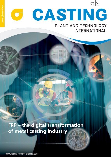
FRP – the digital transformation<br />
of metal casting industry
EDITORIAL<br />
Adjusting screws<br />
to optimize casting!<br />
In the foundries of the 21st century it is no longer merely a matter of mass<br />
production with maximum productivity, but increasingly making castings of<br />
higher quality, with greater energy efficiency, greater flexibility – and thus<br />
increased future-orientation. The issue that you are currently holding offers<br />
some examples of this. There is, for example, the expert analysis by Heinz<br />
Kadelka from Linde Gas in Düsseldorf, who has examined the current possibilities<br />
of pre-warming ladles by means of porous burners and natural gas oxygen<br />
burners. Turn to P. 10 to find out which burner system could optimize<br />
your casting process.<br />
The specialist article by Steffen Geisweid and Dennis Wolzenburg from Heinrich<br />
Wagner Sinto is another highlight. They report on the installation of a<br />
high-tech EFA-SD Seiatsu.plus molding plant and P-30-M casting plant at<br />
M. Busch in Wehrstapel, Germany. These so-called Foundry 3plus systems<br />
represent the current state-of-the-art in modern molding plant construction.<br />
Find out more on P. 20.<br />
There are also numerous possibilities for improving casting technology –<br />
whether by optimizing production with ANSYS Space-Claim software, used at<br />
Eisenwerke Erla in Schwarzenberg (from P. 24), by simulating castings with<br />
Magmasoft at the large Chinese FAW automotive foundry in Changchun (from<br />
P. 26), or through the use of 3-D printers at the Industry 4.0 Christenguss<br />
foundry in Switzerland (from P. 30). The aims that they all share are always<br />
greater flexibility, higher quality, and the maximum possible exploitation of<br />
design freedom during casting.<br />
This issue is also dedicated to a topic that is sometimes only mentioned at the<br />
fringes of the foundry sector, but which should receive far more attention:<br />
safety at work. The global player Georg Fischer (GF) from Schaffhausen in Switzerland<br />
has declared war on sources of danger at foundries with its zero-risk<br />
campaign: awareness of this topic among the workforce has been raised with<br />
poster motifs and a variety of events. The result: the accident rate has fallen<br />
considerably. Tina Köhler, head of communications at GF, stresses that many<br />
people still consider foundries to be dangerous places. “We need to get away<br />
from this image, so we have to do something about safety at work,” she is<br />
convinced. More about this on P. 32.<br />
Have a good read !<br />
Robert Piterek<br />
e-mail: robert.piterek@bdguss.de<br />
Casting Plant & Technology 2 / <strong>2017</strong> 3
FEATURES<br />
INTERVIEW<br />
with Christopher Boss<br />
“EUROGUSS is to become an even better refection of the industry” 6<br />
MATERIALS<br />
Strunz, Alexander<br />
High-performance tungsten-based materials enable<br />
improved casting process 8<br />
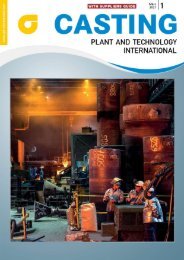
Cover-Photo:<br />
RGU GmbH<br />
Karl-Harr Str. 1<br />
44263 Dortmund<br />
Tel.: +49 (0) 231 419970<br />
Fax: +49 (0) 231 41997-99<br />
info@rgu.de<br />
www.rgu.de<br />
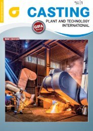
The software company RGU, which has<br />
provided the cover image to us, focuses<br />
exclusively on foundries. FRP stands for<br />
Foundry Resource Planning (derived from<br />
Enterprise Resource Planning, ERP). Read<br />
more on RGU on page 43.<br />
MELTING SHOP<br />
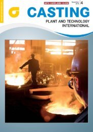
Kadelka, Heinz; Weber, Mike<br />
Ladle heating examined under the aspects of energy<br />
<br />
CASTING TECHNOLOGY<br />
Geisweid, Steffen; Wolzenburg, Dennis<br />
Commissioning of Foundry 3plus at M. Busch in Wehrstapel 20<br />
SIMULATION<br />
Tosse, Thomas<br />
Quicker solution concepts with ANSYS SpaceClaim 24<br />
Baosheng, Lu<br />
Manufacturability of a cylinder block sand core 26<br />
<br />
xx 10 xx 20<br />
How do porous burners perform in camparison to natural<br />
<br />
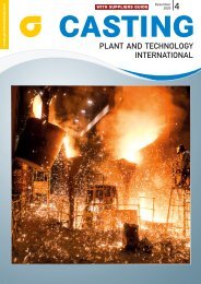
Linde Gas and Gienanth foundry (Photo: Linde Gas)<br />
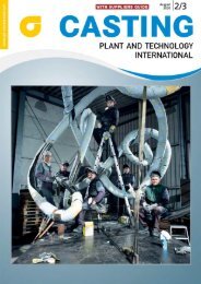
With the commissioning of Foundry 3plus the German<br />
foundry M.Busch has made one of the largest investments<br />
of its company history (Photo: M. Busch)
CASTING<br />
2 | <strong>2017</strong><br />
PLANT AND TECHNOLOGY<br />
INTERNATIONAL<br />
AUTOMATION<br />
Dizdarevic, Mirela<br />
On the way to “Casting 4.0” 30<br />
WORK SAFETY<br />
Piterek, Robert<br />
On course for a new safety culture 32<br />
CLEANING, FETTLING & FINISHING<br />
Paarmann, Ralf<br />
The future is big! 36<br />
COMPANY<br />
Beste, Dieter<br />
Matthies Druckguss: combining tradtion with innovation 40<br />
COLUMNS<br />
Editorial 3<br />
News in brief 43<br />
Brochures 48<br />
Fairs and congresses/Ad index 50<br />
Preview/Imprint 51<br />
xx 30<br />
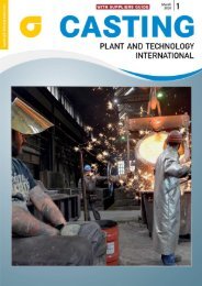
With its vision of Guss 4.0, Christenguss AG of Bergdietikon in Switzerland is also blazing the trail into a digital future. The<br />
foundry manufactures complex sand casting molds in a 3-D printing process. Florian Christen, CEO of a traditional family<br />
business in its fourth generation sees his company as an innovation technology leader (Photo: Christenguss AG)
INTERVIEW<br />
“EUROGUSS is to become an even<br />
better refection of the industry”<br />
From 16 to 18 January 2018, the European die castings sector will meet once again in Nuremberg<br />
at the EUROGUSS trade fair. The exhibitors’ applications are ongoing, the trade fair preparations<br />
in full swing. We spoke to Christopher Boss (31), the new Director Exhibitions, about the<br />
development of EUROGUSS and the international involvement of the NürnbergMesse Group in<br />
the die casting sector. Boss has a degree in business science, has been in the trade fair and exhibition<br />
branch for around 10 years and has worked for NürnbergMesse for around one year.<br />
EUROGUSS 2016 was the most successful<br />
ever staged. With around 580 exhibitors,<br />
more than 12,000 visitors and<br />
the additionally-occupied exhibition<br />
hall, it set new records. You recently<br />
took over as Director Exhibitions from<br />
Heike Slotta, who in future – continuing<br />
her strong bond with EUROGUSS<br />
– will be increasingly involved strategically.<br />
Which objectives have you set<br />
yourself for the coming fair?<br />
In Europe, EUROGUSS is the leading trade<br />
fair for the entire die-casting value-added<br />
chain: from raw materials through to<br />
technology and processes up to finished<br />
products. I was fortunate to immediately<br />
experience the fair live already in my<br />
second week at work and I’m delighted<br />
to continue to be involved in future in<br />
shaping this meeting place which is recognized<br />
and popular in the sector.<br />
In terms of both exhibitors as well as<br />
visitors, EUROGUSS has in recent years<br />
recorded impressive growth rates. My<br />
objective, together with the team, is to<br />
continue this growth trend. In 2018,<br />
we are seeking to break the 600-mark<br />
for exhibitors and further increase internationality.<br />
How would you like to reach this objective?<br />
Since I started at NürnbergMesse, I’ve<br />
been travelling a lot to customers and<br />
events at home and abroad. I have conducted<br />
numerous, interesting, specialist<br />
discussions and meetings aimed at<br />
getting to know the sector better and<br />
finding out which adjustments we can<br />
make in order to establish EUROGUSS<br />
even more strongly as a mirror for<br />
Christopher Boss is new Director Exhibitions of the EUROGUSS Trade fair in Nuremberg,<br />
Germany (Photo: NürnbergMesse)<br />
the sector. We will retain the product<br />
range core of the event, but further<br />
extend the range depth. The focus of<br />
EUROGUSS will continue to be Europe.<br />
Of course, die casting is in particular<br />
dependent on the automotive sector,<br />
but we will also be increasingly inviting<br />
target groups from other sectors to<br />
EUROGUSS, for whom the die casting<br />
process with its many advantages offers<br />
a genuine alternative.<br />
Are there changes to the trade fair<br />
concept?<br />
The EUROGUSS concept has proved<br />
itself most effectively. This is confirmed<br />
to us not only by the fantastic<br />
exhibitor and visitor figures from the<br />
last event, but also by the top ratings<br />
awarded in the exhibitors’ and visitors’<br />
survey. 98 % of the visitors surveyed<br />
stated that they were satisfied with the<br />
range presented at the fair and 94 % of<br />
exhibitors assess their trade fair participation<br />
as an overall success. So we<br />
should not tinker with the trade fair<br />
concept in general. Nevertheless, it is<br />
necessary to further refine the concept<br />
and extend the trade fair range to include<br />
attractive formats.<br />
What should exhibitors and visitors<br />
look forward to at the next EURO-<br />
GUSS in 2018?<br />
The exhibitors’ applications process<br />
is going very well. Three quar-<br />
6 Casting Plant & Technology 2 / <strong>2017</strong>
ters of exhibition space is already<br />
booked around 10 months before<br />
the event. Many exhibitors have enlarged<br />
their stands. Of course, all the<br />
market leaders are once again present,<br />
but new exhibitors are also on<br />
board. The theme of surface technology,<br />
which was highlighted for<br />
the first time at EUROGUSS 2016, is<br />
being extended further and presented<br />
in a pavilion. The “Forschung, die<br />
Wissen schafft” (Research for Knowledge)<br />
special show, where the latest<br />
research projects from universities<br />
and technical colleges are presented,<br />
has been popular with the trade visitors<br />
for years. It too will of course also<br />
be part of the event again. The exhibitors<br />
and visitors can also look forward<br />
to interesting lectures and presentations<br />
on current themes and issues<br />
at the “<strong>International</strong>er Deutscher<br />
Druckgusstag” (<strong>International</strong> German<br />
Die Casting Congress) specialist<br />
event, which is being organized by<br />
our esteemed partner, the Verband<br />
Deutscher Druckgießereien (VDD,<br />
Association of German Die-Casting<br />
Foundries).<br />
There will be excitement surrounding<br />
the award presentations for the<br />
<strong>International</strong> Aluminium Die Casting<br />
Competition and the Zinc Die<br />
Casting Competition. As you can see,<br />
there is once again a great deal on offer<br />
at EUROGUSS.<br />
In addition to EUROGUSS in Nuremberg,<br />
the NürnbergMesse Group,<br />
within the framework of its internationalization<br />
strategy, has indeed for<br />
several years also been successfully<br />
staging die casting trade fairs and<br />
exhibitions worldwide, for example<br />
in China and India. What advantages<br />
does that bring to the company?<br />
Yes, that is correct. For several years,<br />
the NürnbergMesse Group has been<br />
strengthening the positioning of its<br />
successful events at the home location<br />
of Nuremberg through so-called<br />
product families worldwide. That<br />
means in the case of EUROGUSS that<br />
this event is functioning as the mother<br />
of the product family so to speak<br />
and has offshoots in attractive foreign<br />
markets outside Europe. As an<br />
international product manager, I am<br />
trying to make use of the synergy effects<br />
between the individual members<br />
of the product family in the various<br />
markets. It is important for us that<br />
these events are always perfectly tailored<br />
to the requirements of their respective<br />
markets. We are accompanying<br />
our customers on their way into<br />
these exciting and prospering markets<br />
and offering them the proven exhibition<br />
quality and service they are<br />
familiar with from Nuremberg. In this<br />
connection, for example last December,<br />
the largest die casting trade fair<br />
in India was held with around 140<br />
exhibitors, ALUCAST, organized and<br />
staged by NürnbergMesse India. According<br />
to forecasts, the Indian die<br />
casting market offers great growth<br />
potential for European companies.<br />
The date for the next ALUCAST is 6<br />
to 8 December 2018 in Delhi. In China<br />
too, the largest die casting market<br />
in the world, we have been active<br />
since 2013 and are involved in shaping<br />
the dynamic development of the<br />
CHINA DIECASTING trade fair in<br />
Shanghai through our subsidiary<br />
NürnbergMesse China. Last year,<br />
CHINA DIECASTING registered 295<br />
exhibitors and 12,<strong>02</strong>7 trade visitors.<br />
The next fair will be held from 19 to<br />
21 July <strong>2017</strong>. We are expecting around<br />
350 exhibitors and 15,000 trade visitors.<br />
www.nuernbergmesse.de/en<br />
your competent partner<br />
for Cast Iron !<br />
Gray cast iron up to 70 t<br />
Nodular cast iron up to 50 t<br />
Steel cast<br />
up to 6 t<br />
Mechanical processing<br />
Painting<br />
Dimensions: length: 14,5 m<br />
Ø 7 m<br />
weight 70 t<br />
EMDE Industrie-Technik GmbH D-39418 Staßfurt<br />
+49 (0) 39 25 - 985 0 www.emde.de info@emde.de<br />
Casting Plant & Technology 2 / <strong>2017</strong> 7
MATERIALS<br />
Alexander Strunz, Munich<br />
High-performance tungsten-based<br />
materials enable improved casting<br />
process<br />
Bayerische Metallwerke GmbH, Dachau, Germany, offers an innovative material for casting tool<br />
construction with its product family Triamet A, a tungsten-based heavy metal alloy that can<br />
withstand more frequent temperature changes<br />
Fire cracks and corrosion are the most<br />
common types of casting tool damage<br />
in light metal casting. Usually such damage<br />
reduces product quality, which may<br />
worsen even further under some circumstances<br />
due to adhesion or inadequate<br />
heat dissipation. With its Triamet A product<br />
family, a tungsten-based heavy metal<br />
alloy, Bayerische Metallwerke GmbH offers<br />
an innovative and ecological alternative<br />
that avoids these problems. Thanks<br />
to a tungsten content of up to 98 %, the<br />
Triamet A materials withstand the stresses<br />
of frequent temperature changes in<br />
the casting process over the long term<br />
and set themselves apart with high corrosion<br />
resistance compared to aluminium<br />
and copper alloys.<br />
With many types of hot work steel<br />
used in light metal casting for the production<br />
of tools, the hardness and<br />
strength decrease relatively quickly<br />
due to the high thermal stresses. Crack<br />
formation caused by thermal fatigue of<br />
the material is common. This can reduce<br />
the quality of the end product<br />
and lead to significant financial costs<br />
The Triamet A materials are used primarily in<br />
gravity diecasting and high-pressure diecasting,<br />
for instance for the production of aluminium<br />
rims and cylinder heads<br />
(Photos: Wolfram Industry)<br />
8 Casting Plant & Technology 2 / <strong>2017</strong>
and time expenditures for repair work<br />
and loss of use.<br />
With the Triamet A product series,<br />
Bayerische Metallwerke GmbH offers<br />
various tungsten-based alloys that can<br />
avoid these problems. Tools made of<br />
Triamet A are highly resistant to liquid<br />
aluminium and magnesium. This can<br />
increase the service life by 10 to 500<br />
times compared to conventional materials,<br />
depending on the field of application<br />
and the type of casting process.<br />
The negligibly small alloy formation<br />
tendency and the formation of a natural<br />
separating layer counteract sticking<br />
of the work piece to the casting mold,<br />
which has a positive impact on product<br />
quality as well.<br />
Low thermal expansion co-<br />
<br />
Fire cracks in casting molds are caused<br />
mainly by thermal fatigue due to alternating<br />
compressive and tensile stress<br />
on the tools. The lower the thermal<br />
conductivity and the higher the thermal<br />
expansion coefficient of a material,<br />
the greater this stress will be. Compared<br />
to the commonly used steel, the<br />
thermal conductivity of Triamet A at<br />
70 to 105 W/mK is about 3 to 5 times<br />
higher while the thermal expansion<br />
coefficient at 5.2-6.5 [10 -6 K -1 ] is simultaneously<br />
only about 50 %. This greatly<br />
reduces stresses in the tool. The high<br />
resistance to temperature changes significantly<br />
reduces the fire cracking tendency<br />
and therefore greatly increases<br />
the service life.<br />
<br />
<br />
binder phase<br />
Bayerische Metallwerke GmbH uses a<br />
nickel and iron binder phase (Figure 1)<br />
for the production of Triamet A, added<br />
to the tungsten powder at the rate of 2<br />
– 10 %. Nickel acts as a catalyst that accelerates<br />
diffusion processes on the surface<br />
of the tungsten power and thereby<br />
reduces the sintering temperature by<br />
about 1,000 °C. Subsequently the Triamet<br />
green parts are sintered at about<br />
1,500 °C – in contrast to the 2,500 °C<br />
required for pure tungsten – so that a<br />
unique microstructure with a spherical<br />
tungsten phase encased by the<br />
binder phase is formed. All Triamet A<br />
series products set themselves apart<br />
with a very high density from 17.0<br />
± 0.15 g/cm 3 for Triamet A17 to about 18.8<br />
± 0.2 g/cm 3 for A19.<br />
The Triamet A materials are used<br />
primarily in gravity die casting and<br />
high-pressure die casting, for instance<br />
for the production of aluminium rims<br />
and cylinder heads.<br />
Figure 1: The lower the proportion of the binder phase, the higher the density will be.<br />
However, the ductility of the heavy metal also increases as the binder proportion rises<br />
http://wolfram-industrie.de/en<br />
Casting Plant & Technology 2 / <strong>2017</strong> 9
used for ladle heating and holding at operating temperature (Photos & Graphics: Linde Gas)<br />
Heinz Kadelka, Linde Gas, Düsseldorf, and Mike Weber, Gienanth GmbH, Eisenberg<br />
Ladle heating examined under the<br />
<br />
cost optimization<br />
<br />
<br />
ers<br />
employed to heat ladles used for pouring and treating melts of grey cast, ductile or compacted<br />
graphite iron<br />
Field experiment<br />
The objectives of the experiment were to<br />
examine the economic efficiency, flexibility,<br />
energy efficiency, service life, sintering<br />
and temperature changes during<br />
and associated with ladle heating. The<br />
tests were conducted with a 4-t pouring<br />
ladle for cast iron melts. They involved<br />
the heating of the ladle by porous burners<br />
and natural gas/oxygen burners.<br />
Background<br />
Ladles account for a significant share of<br />
the total energy input in iron melting<br />
processes. They have to be heated to operating<br />
temperature and then continu-<br />
10 Casting Plant & Technology 2 / <strong>2017</strong>
above the inside bottom<br />
All in<br />
one line<br />
M3: In the middle of the refractory<br />
<br />
inside bottom<br />
<br />
<br />
the inside bottom<br />
Figure 1:<br />
ously held at that temperature. This is<br />
to be performed with maximum efficiency<br />
and flexibility, while subjecting<br />
the ladle to fewest possible temperature<br />
changes, in order to maximize the lining<br />
life and minimize ladle repair.<br />
980<br />
900<br />
Temperature measurement in the<br />
<br />
<br />
Test set-up<br />
Figure 1 shows the positions of the<br />
thermocouples in the refractory lining<br />
of the 4-t pouring ladle.<br />
Inherent energy content of<br />
a pouring ladle at operating<br />
temperature<br />
Through-heating of a ladle depends<br />
largely on the heat content of the refractory<br />
material, especially the superheating<br />
of the inside surface zone. After<br />
the molten metal has been filled<br />
into the ladle, the thermal energy<br />
from the melt is introduced into the<br />
ladle and transferred towards the outside<br />
via the refractory lining. Especially,<br />
the reading at measuring point M 1,<br />
at 2.5 cm from the inside refractory surface,<br />
shows a pronounced temperature<br />
rise (approx. 970 °C; Figure 2) after the<br />
molten iron has been filled into the ladle.<br />
For the here presented experiment,<br />
the ladle was filled with 3 t of molten<br />
iron, simulating optimal through-heating.<br />
After 8 min, the melt was poured.<br />
At that stage, the first 2.5 cm of the refractory<br />
lining thickness were superheated<br />
(Figure 3). Within this surface<br />
layer of only 2.5 cm thickness, a temperature<br />
difference of more than 550 °C<br />
Temperature in °C<br />
820<br />
740<br />
660<br />
580<br />
500<br />
<br />
M3<br />
<br />
M2<br />
<br />
420<br />
12:01:26 12:<strong>02</strong>:53 12:04:19 12:05:46 12:07:12 12:07:12 12:10:05 12:11:31 12:12:58<br />
Figure 2: Heating of the refractory lining by the melt for approx. 8 min. Thermal be-<br />
<br />
the iron melt in the ladle at 12 o’clock: 1,501 °C<br />
between the surface and M 1 was measured.<br />
In case of ladle preheating by<br />
burners, it is recommended that care<br />
should be taken to ensure that this heat<br />
content be input by the burner. Otherwise<br />
it would be extracted from melt.<br />
Time in min<br />
Resistance to temperature<br />
changes<br />
When ladles are being filled with molten<br />
metal, the inside surface layer of the<br />
ladles heats up. The temperature transfer<br />
from the melt is lower when the temperature<br />
of this layer is already at a high<br />
level before the molten metal is filled in,<br />
(figure 3). When this layer is “cold” or<br />
has not been heated up to a sufficiently<br />
high level, the temperature changes<br />
will be great, leading to early wear,<br />
short lifetimes and slag caking in the ladles.<br />
After pouring, this energy content<br />
is transferred into the interior of the refractory<br />
lining via the superheated surface<br />
zone, as shown in figure 3.<br />
Casting Plant & Technology 2 / <strong>2017</strong> 11
MELTING SHOP<br />
Cooling down of the refractory<br />
material<br />
In Figure 4, this process can be observed<br />
to take place at M 3 for a period<br />
of approximately 30 min from 14:04 to<br />
14:20 h. The thermal energy is introduced<br />
into the refractory material like a<br />
wave, resulting in a rise in temperature.<br />
The superheated mass in the surface layer<br />
of the refractory lining (walls and bottom)<br />
can be assumed to amount to more<br />
than 200 kg. Heat content: approx. 4 to<br />
5 m 3 of natural gas. Even if the inside ladle<br />
surface is already “cold” (dark red),<br />
a few millimeters down into the refractory<br />
lining temperatures clearly above<br />
1,200 °C must be expected.<br />
Criteria for the comparison<br />
The basic objective was to achieve natural<br />
conditions as described above<br />
as “the inherent energy content of a<br />
pouring ladle at operating temperature”.<br />
For the investigated 4-t pouring<br />
ladle, the temperature level in the middle<br />
of the refractory lining was used as<br />
a basis of reference. The objective was<br />
to heat the ladle by means of the different<br />
burner systems in such a way<br />
that these temperatures were reliably<br />
reached and held at a constant level.<br />
During the experiment, at measurement<br />
point M3 in the middle of the refractory<br />
lining temperatures between<br />
approx. 640 °C and approx. 660 °C<br />
were measured. At M1 near the inside<br />
surface, temperatures above 820 °C<br />
were to be reached, in order to achieve<br />
the same temperature level as a ladle in<br />
the actual production process.<br />
Temperature in °C<br />
1600<br />
1440<br />
1280<br />
1120<br />
960<br />
800<br />
<br />
<br />
0 5 10 15 20 25 30<br />
Distance from inside surface in mm<br />
Figure 3: Heat transfer into the inside refractory surface zone (2.5 mm); M1 the surface<br />
temperature corresponds to the molten iron temperature, idealized (after “8 min”)<br />
Temperature in °C<br />
850<br />
800<br />
750<br />
14:04:53<br />
854°C<br />
<br />
700<br />
15:04<br />
M3<br />
652 °C<br />
650 639°C<br />
605 °C<br />
600<br />
550<br />
M2<br />
559 °C<br />
572 °C<br />
500<br />
14:<strong>02</strong>:24 14:09:36 14:16:48 14:24:00 14:31:12 14:38:24 14:45:36 14:52:48 15:00:00<br />
Time in min<br />
Figure 4: Temperature curves after the melt was poured, with the ladle covered and<br />
without use of burner<br />
Preliminary considerations<br />
concerning the ladle management<br />
and current practice<br />
Ladle heating by means of porous<br />
burners, as currently practiced in the<br />
foundry, was used as the reference for<br />
assessing the economic efficiency. Actually,<br />
the current situation could already<br />
be optimized by simple means,<br />
e.g. improved ladle covering in connection<br />
with a precisely controlled<br />
natural gas/air ratio. Also thermocouples<br />
installed in the ladle lid, which<br />
would control or interrupt the operation<br />
of the burner as required after<br />
reaching the pre-defined temperatures,<br />
would provide an improvement.<br />
Creating awareness among the operating<br />
staff may also lead to a significant<br />
reduction in energy use. Only after<br />
these conventional measures have<br />
been implemented should the reference<br />
situation be re-defined. This situation<br />
should be used as decision basis<br />
for future heating strategies. The comparison<br />
was based on the neutral cost<br />
assumption, including of course technical<br />
oxygen costs. Generally, it is attempted<br />
to achieve an optimal or physically<br />
feasible situation as well as the<br />
effect of “near-surface zone superheating”,<br />
in a cost-neutral way no matter<br />
which type of burner system was used.<br />
Heating of the 4-t pouring ladle<br />
by natural/gas oxygen<br />
burners (oxyfuel burners)<br />
After 90 min, the self-defined target<br />
was reached attaining a temperature of<br />
649 °C. At 2.5 cm from the inside surface,<br />
the temperature reached 832 °C<br />
(Figure 5), which corresponds to the<br />
12 Casting Plant & Technology 2 / <strong>2017</strong>
MELTING SHOP<br />
temperature attained in the ladle at operating<br />
temperature after melt filling (figure<br />
2: 823 °C). The surface temperature of<br />
the refractory lining was securely above<br />
1,550 °C, which is in line with other measurements.<br />
The burner achieved a degree<br />
of efficiency (ETA v) of 71 %.<br />
Heating of the 4-t pouring ladle<br />
by porous burners<br />
Porous burners<br />
The current design provides the possibility<br />
of individual height adjustment.<br />
The burner roof is suitable for almost<br />
all ladle diameters. The ladles are covered<br />
in such a way that there is only a<br />
small open gap at the circumference.<br />
Waste gas removal is via a tube integrated<br />
into the roof. The combustion<br />
gas and the combustion air are guided<br />
through porous ceramic material<br />
and ignited inside a high-temperature-resistant<br />
stainless steel tube. The<br />
tube, which is connected with the ladle<br />
lid, is lowered down into the ladle<br />
until the burner sits on the ladle rim.<br />
The combustion gases will then rise between<br />
the inside ladle wall and the outside<br />
burner tube.<br />
Constraints<br />
For material-technological reasons,<br />
the gas temperature must not exceed<br />
a certain limit. In the experiment,<br />
the temperature was not to exceed<br />
1,000 °C (thermocouple at the outside<br />
of the burner tube). Iron foundry<br />
Gienanth in Eisenberg defined the<br />
target temperature at 1,000 °C (taking<br />
into account design-related and material-specific<br />
requirements to avoid excessive<br />
thermal stress).<br />
Parameters of the experiments<br />
Natural gas input was determined to<br />
be 12.44 m 3 /h; the maximum temperature<br />
measured at the surface of<br />
the burner tube was 1,<strong>02</strong>0 °C. The maximal<br />
waste gas temperature was just below<br />
1,000 °C. From these facts it can<br />
be derived that heat transfer into the<br />
refractory material does take place at<br />
this temperature.<br />
Achievement of target temperatures<br />
at the measuring points in the refractory<br />
lining<br />
Refractory temperature in °C<br />
With a total energy input of 56 m 3 of<br />
natural gas and after an average heating<br />
time of 4.5 h , 538 °C were measured<br />
at M3 in the middle of the refractory<br />
lining. At 2.5 cm from the<br />
inside surface, 650 °C were measured<br />
(M1, ). The efficiency relative<br />
to the temperature in the middle<br />
of the refractory lining was calculated<br />
to amount to approx. 47 %. The porous<br />
burner failed to reach the target<br />
of heating the ladle to operating temperatures<br />
(> 640 °C) at neutral costs<br />
(538 °C). Consequently porous burners<br />
are unable to achieve the effect of<br />
surface zone superheating.<br />
General comparison of the<br />
preheating performance<br />
After approx. 4.5 h (270 min), heating<br />
by means of the porous burner<br />
achieved a temperature of 538 °C (ETA<br />
v 47 %). In contrast, the oxyfuel burner<br />
achieved this temperature already after<br />
1.22 h (73 min), (ETA v 71 %). The<br />
oxyfuel burner reached the temperature<br />
level of the porous burner (538 °C)<br />
with approx. 10 % less energy costs (in-<br />
Figure 5: Heating of a 4-t ladle to operating temperature by means of a natural gas/oxy-<br />
2<br />
Refractory temperature in °C<br />
680<br />
560<br />
440<br />
320<br />
200<br />
1000<br />
800<br />
600<br />
400<br />
200<br />
0<br />
<br />
Start<br />
<br />
<br />
<br />
10:04:48 10:19:12 10:33:36 10:48:00 11:<strong>02</strong>:24 11:16:48 11:31:12 11:45:36 12:00:00<br />
<br />
<br />
<br />
Start<br />
<br />
<br />
Time axis in min<br />
Heating curve of a porous burner. Comparison of a porous burners with an O 2<br />
burner<br />
M3<br />
M2<br />
<br />
<br />
<br />
<br />
<br />
80<br />
08:24:00 09:36:00 10:48:00 12:00:00 13:12:00 14:24:00<br />
M3<br />
M2<br />
Heating time in min<br />
<br />
<br />
14 Casting Plant & Technology 2 / <strong>2017</strong>
cluding technical oxygen) (Figure 7).<br />
Prolonging the heating time of the porous<br />
burner leads only to an insignificant<br />
increase in temperature. At the<br />
same time, the efficiency (ETA v) decreases<br />
dramatically. In the experiments,<br />
the oxyfuel burner achieved<br />
the actual temperature level of the ladle<br />
in the casting process already after<br />
90 min (649 °C). Corresponding<br />
comparisons are provided in figures 2<br />
and 5. The energy input to make up<br />
the difference in temperatures in the<br />
refractory lining measured in M3 in<br />
case of porous burner use (538 °C) and<br />
in case of oxyfuel burner use (649 °C)<br />
has to be compensated by thermal energy<br />
transferred from the molten metal<br />
(higher tapping temperature) into the<br />
refractory lining. However, it would<br />
be more useful to employ burners to<br />
achieve this exchange of energy rather<br />
than to accept the negative metallurgical<br />
effects of an excessively high<br />
tapping temperature.<br />
Temperature in °C<br />
600<br />
500<br />
400<br />
300<br />
200<br />
100<br />
0<br />
73 min<br />
<br />
<br />
<br />
0 50 100 150 200 250 300<br />
Figure 7: Heating curves of a porous burner versus a natural gas/oxygen burner<br />
<br />
<br />
M3 porous burner<br />
<br />
Time in min<br />
267 min<br />
<br />
gies<br />
on the temperature<br />
<br />
With the melt being tapped from the<br />
induction furnace at almost identical<br />
temperatures in both cases<br />
(1,530/1,531 °C), 3 min after ladle filling<br />
the temperature difference between<br />
porous burner use and oxyfuel burner<br />
use amounts to 29 K (1498/1469 °C), af-<br />
Competence in<br />
Shot Blast Technology<br />
We offer a complete service in surface preparation technology,<br />
not just as machine designers and manufacturers.<br />
Our emphasis is on providing reliable service on:<br />
• Wear and Spare Parts<br />
• Repair and (remote) maintenance<br />
• Inspection and process advice<br />
• Machine upgrades and performance<br />
enhancement<br />
• Upgraded used machines<br />
AGTOS<br />
Gesellschaft für technische Oberflächensysteme mbH<br />
Gutenbergstraße 14 · D-48282 Emsdetten<br />
Tel. +49(0)2572 96<strong>02</strong>6-0 · info@agtos.de<br />
www.agtos.com<br />
156-11/13-4c-GB<br />
Casting Plant & Technology 2 / <strong>2017</strong> 15
MELTING SHOP<br />
ter another 5 min the difference has increased<br />
to 63 K (Figure 8). In the experiment,<br />
temperature losses of 125 °C were<br />
measured in the ladle heated with the<br />
porous burner. In the ladle heated with<br />
the oxyfuel burner, temperature losses<br />
of only 61 K were found – a difference<br />
of 64 K between the two burner types.<br />
From this a potential for lowering the<br />
tapping temperature in the induction<br />
furnace can be derived. The advantage:<br />
Cost savings on electrical energy and<br />
proven metallurgical benefits.The process<br />
advantage of a natural gas/oxygen<br />
burner is shown in figure 7. The physical<br />
aspects will be discussed below in<br />
the paragraphs dealing with convection<br />
and radiation. The reference temperatures<br />
in figure 2, which were measured<br />
as part of the experiment, were reached<br />
with natural gas/oxygen heating, thus<br />
fulfilling the requirement for the comparison:<br />
measuring point M1, near the<br />
inside surface, approx. 820 °C and measuring<br />
point M3, in the middle of the<br />
refractory lining, approx. 640 - 660 °C.<br />
Ladle heating by means of the oxyfuel<br />
burner differs only marginally from a ladle<br />
in the production process heated by<br />
molten metal. Particularly Figures 9 and<br />
3 show that the inside surface zone retains<br />
a similar temperature level.<br />
Temperature difference between<br />
the inside surface of<br />
the refractory lining and the<br />
subsurface measuring point<br />
M1 (25 mm)<br />
An important aspect to be considered is<br />
the energy content of the temperature<br />
difference. As shown in figure 9, after<br />
4.5 h the porous burner achieved a temperature<br />
of 990 °C at the surface of the<br />
refractory lining. Compared to the temperature<br />
achieved by the oxyfuel burner,<br />
there is a different of more than 560 K.<br />
The energy content in the surface zone of<br />
the refractory lining is the same as that of<br />
a ladle at operating temperature.<br />
Accordingly, whenever the ladle is<br />
heated by a porous burner, the refractory<br />
lining needs additional energy input<br />
of 185 K to make up for the difference<br />
(M1, 647/832 °C) (figures 5 and 6). This<br />
additional energy has to come from the<br />
melting process. Consequently, higher<br />
melt temperatures would be necessary.<br />
Temperature in °C<br />
1520<br />
1500<br />
1480<br />
1460<br />
1440<br />
1420<br />
1400<br />
Refractory temperature in °C<br />
1350<br />
1150<br />
950<br />
750<br />
500<br />
350<br />
150<br />
1530 1531<br />
Melting temperature<br />
in induction furnace<br />
Figure 8: Iron temperatures for different heating methods. Temperature level of porous<br />
burner versus O 2<br />
burner<br />
0 2 4 6 8 10 12<br />
Temperature at different refactory lining depths in cm<br />
Figure 9: Comparison of the achieved temperatures at the measuring points in the inside<br />
lining surface zone, in the middle of the lining and in the lining close to the ladle wall.<br />
Comparison of heating by molten metal, natural gas/oxygen burner and porous burner<br />
Physical aspects and comparison<br />
of natural gas/air combustion<br />
and natural gas/oxygen<br />
combustion<br />
Flame temperature<br />
The flame temperature basically depends<br />
on the natural gas/air or natural<br />
gas/oxygen ratio and the burner design.<br />
The comparison is based on the<br />
use of natural gas (methane, figure 9).<br />
In practice, natural gas/air combustion<br />
only achieves flame temperatures of<br />
1498<br />
Temperature in ladle, 3 min<br />
<br />
<br />
1469 1469<br />
Temperature<br />
molten iron<br />
1406<br />
<br />
<br />
<br />
burner<br />
<br />
Porous burner<br />
Porous burner<br />
Temperature, 8 min after<br />
pouring of the melt<br />
< 1,700 to 1,800 °C, O 2<br />
burners temperatures<br />
< 2,850 °C.<br />
Combustion with air versus combustion<br />
with technical oxygen (approximate<br />
calculation)<br />
» Original fuel rate:10 m³/h of natural<br />
gas (CH4).<br />
» Combustion at 100 m³/h of air.<br />
» Combustion requires approx.<br />
20 m³/h of oxygen and approx. 80 m³<br />
of nitrogen (air: 20,9 % O 2<br />
, 78 % N 2<br />
).<br />
16 Casting Plant & Technology 2 / <strong>2017</strong>
Spectral radiation<br />
Spectral radiation density<br />
Wave length<br />
Figure 10: Planck’s radiation law<br />
Fuel<br />
<br />
temperatures<br />
<br />
<br />
Propane/Butane <br />
Hydrogen <br />
Methane (natural gas) <br />
<br />
Table 1: <br />
Temperature Control.<br />
Smart. Reliable.<br />
» Combustion products: H 2<br />
O and CO 2<br />
.<br />
» Lost energy (N 2<br />
): If a temperature of<br />
approx. 1,100 °C is measured in the<br />
waste gas flow of the ladle, 33 % of the<br />
required energy provided by natural<br />
gas is needed to heat up the nitrogen.<br />
Combustion with O 2<br />
In case of combustion with technical<br />
oxygen no burden in the form of nitrogen<br />
needs to be heated. Consequently,<br />
only 6.6 m 3 /h of natural gas are needed.<br />
The higher flame temperature in<br />
case of combustion with pure oxygen<br />
(2,860 °C according to ) provides<br />
a further energetic benefit, namely the<br />
radiation effect (Figure 10). Versus combustion<br />
with air, this effect reduces the<br />
necessary energy input by another approx.<br />
15 % . Compared to combustion<br />
with air, the use of oxygen reduces the<br />
consumption of natural gas to approx.<br />
5.1 m 3 /h for virtually the same combustion<br />
result. This equals a reduction by<br />
approx. 50 %. Natural gas/oxygen combustion<br />
achieves adiabatic temperatures<br />
of more than 2,860 °C. All state-of-theart<br />
burner equipment provides the possibility<br />
of accurately adjusting the mixing<br />
ratio (stoichiometry). Therefore, the<br />
differences in efficiency depend exclusively<br />
on the burner design.<br />
Heat transfer by radiation<br />
Figure 11 illustrates the heat transfer<br />
by radiation.<br />
» Radiation in case of porous burner<br />
use: Gas temperature 1,300 K,<br />
Proven quality<br />
& Swiss precision<br />
Reliable Swiss quality, in use successfully<br />
for 50 years. The temperature<br />
control units from REGLOPLAS are<br />
convincing because of their precision,<br />
long service life and compatibility.<br />
Casting Plant & Technology 2 / <strong>2017</strong> 17<br />
www.regloplas.com
MELTING SHOP<br />
wave length 2 μm, spectral radiance<br />
105 W/ (m² μm).<br />
» Radiation in case of natural gas/oxygen<br />
combustion: Gas temperature<br />
3,100 K, wave length 0.77 μm, spectral<br />
radiance 106 W/ (m² μm). As a result<br />
of the higher temperatures, the<br />
wave lengths are shorter. This produces<br />
tenfold higher heat transfer rates.<br />
Heat transfer by convection<br />
No physical strategy for ladle heating<br />
can be derived from the calculation<br />
of the heat transfer from a gas mixture<br />
of 1,000 °C into a refractory wall<br />
of 1,300 °C. Actually, the wall surface<br />
transfers heat into the combustion gas.<br />
The consequence is that heat is extracted<br />
from the refractory wall (surface),<br />
leading to a drop in the wall temperature<br />
(figure 11), but not to the heating<br />
of the ladle.<br />
Fluid temperature<br />
Surface<br />
temperature<br />
Fluid 1<br />
Thermal interface<br />
Solid wall<br />
Figure 11: Principle of heat transfer by convection<br />
Thermal interface<br />
Fluid 2<br />
Surface<br />
temperature<br />
Fluid temperature<br />
Negative convection<br />
Particularly during this phase the surface<br />
temperature has to be kept at a<br />
high level in order for the ladle to retain<br />
its operating temperatures for the<br />
next melt without suffering any major<br />
temperature changes.<br />
Comparison: Holding at temperature<br />
– Heating up and<br />
holding an in-process ladle at<br />
operating temperature<br />
Porous burner<br />
The burner design as well as the used<br />
materials and their thermal properties<br />
put constraints on the temperature control<br />
between the inside surface of the ladle<br />
and the burner sleeve of the porous<br />
burner system. Consequently, the temperature<br />
depends directly on the materials<br />
used in the porous burner design.<br />
A thermocouple installed in the burner<br />
limits the heating process to a maximum<br />
temperature of approx. 1,000 °C.<br />
It can be assumed that the gas temperature<br />
between the surface of the burner<br />
sleeve and the surface of the refractory<br />
lining in the ladle is not significantly<br />
higher. The natural cooling curve in<br />
Figure 12 represents cooling with the ladle<br />
covered and without any additional<br />
energy input. Immediately covering the<br />
ladle is therefore more efficient than using<br />
a porous burner.<br />
Temperature in °C<br />
800<br />
700<br />
600<br />
500<br />
400<br />
M3 porous burner<br />
<br />
<br />
300<br />
10:04:48 10:19:12 10:33:36 10:48:00 11:<strong>02</strong>:24 11:16:48 11:31:12 11:45:36 12:00:00<br />
Figure 12: Comparison of the natural cooling behaviour of a ladle at operating temperature<br />
in the covered state versus use of porous burner heating for 1 h with 12.5 m <br />
<br />
Burner use<br />
Despite the energy input by the porous<br />
burner, the ladle temperature fell<br />
markedly.<br />
<br />
<br />
the ladle is covered<br />
<br />
burner use<br />
natural gas<br />
Time in min<br />
<br />
<br />
Comparison: Holding at temperature<br />
(M1 (2.5 cm))<br />
The ladle was transferred to the respective<br />
burner stand right after the<br />
melt had been poured. The intention<br />
was to demonstrate that it would be<br />
possible to hold the ladle at a maximum<br />
temperature level. Figure 13<br />
shows that the above explained physical<br />
effects lead to the situation that in<br />
case of porous burner use the surface<br />
(M1) cools down, negating the heating<br />
effect of the hot refractory surface<br />
zone. From this it can be concluded<br />
that the porous burner should only be<br />
used after temperatures < 500 °C have<br />
been reached (M3). This would mean<br />
a waiting time of more than 3 h, without<br />
any actual effect on the intended<br />
18 Casting Plant & Technology 2 / <strong>2017</strong>
Temperature in °C<br />
Figure 13: Comparison of the temperature holding performance of a natural gas/oxygen<br />
burner using 4 m of O 2<br />
versus a porous burner using<br />
of natural gas and air directly after pouring; at M1<br />
Savings euros/year<br />
920<br />
840<br />
760<br />
680<br />
600<br />
0 10<br />
20 30 40 50<br />
30 000<br />
25 000<br />
20 000<br />
15 000<br />
10 000<br />
5000<br />
<br />
repairs<br />
<br />
Porous burner<br />
Time in min<br />
<br />
service life<br />
Savings potential<br />
<br />
Savings on electricity<br />
Figure 14: Savings potential provided by a natural gas/oxygen burner based on approx.<br />
25,000 t of molten metal per year<br />
the use of conventional porous burners.<br />
The shortfall in energy incurred<br />
when using porous burners would<br />
either have to be compensated by a<br />
higher tapping temperature or higher<br />
temperature losses would have to be<br />
tolerated when pouring the first melt<br />
(difference of up to 60 K in case of the<br />
investigated ladle). In the overall comparison,<br />
the cost-benefit ratio is clearly<br />
in favour of the natural/gas oxygen<br />
burner.<br />
The advantages:<br />
» high flexibility, operating temperature<br />
after 60 to 90 min<br />
» short non-productive times<br />
» longer service times<br />
» improved resistance to temperature<br />
changes<br />
» cleaner ladles<br />
» lower tapping temperature of induction<br />
furnace<br />
» less lining repair<br />
Cost advantage of the natural<br />
gas/oxygen burner<br />
Especially the use of natural gas/oxygen<br />
burners for heating the ladle to operating<br />
temperature provides obvious<br />
cost saving potential, optimizing the<br />
overall “thermal costs” of the process<br />
( ). The reduction in necessary<br />
energy costs associated with the melting<br />
process is clearly assessable. Moreover,<br />
the problem of thermal fatigue is<br />
alleviated, guaranteeing extended service<br />
lives in conjunction with the effect<br />
of cleaner ladles. The statement<br />
that the ladles are “cleaner” is backed<br />
by the fact that material caking from<br />
the pouring process melts off at high<br />
temperatures and deposits at the ladle<br />
bottom.<br />
heating of the ladle to operating temperature.<br />
Natural gas/oxygen burner<br />
Immediate use of a natural gas/oxygen<br />
burner requires extra energy and may<br />
lead to ladle overheating. Therefore, it<br />
is indispensible to control the burner<br />
operation by means of thermocouples.<br />
Operating times can be programmed<br />
according to the size of the ladle. The<br />
effect of ladle covering on the operating<br />
temperature and the cooling behaviour<br />
is shown in figure 4. After approx.<br />
60 min, a temperature of 605 °C<br />
(at M 3) is reached, which is almost the<br />
same as in the beginning.<br />
Comparison<br />
By means of natural gas/oxygen burners<br />
it was possible to achieve operating<br />
temperature states very similar to<br />
those in an in-process ladle, at energy<br />
costs not exceeding those involved in<br />
Bottom line<br />
In an iron foundry, the applicability<br />
of porous burners is limited. However,<br />
their use is justified in case of low<br />
pouring temperatures, great wall thicknesses<br />
and for ladle drying. Compared<br />
to this, the use of natural gas/oxygen<br />
burners for ladle heating achieves a<br />
physically optimal operating result at<br />
lower energy costs.<br />
www.linde-gas.de<br />
www.gienanth.com
CASTING TECHNOLOGY<br />
Pouring line during the pouring process of pouring units 1 and 2 (Photos & Graphics: M.Busch)<br />
Steffen Geisweid and Dennis Wolzenburg, Heinrich Wagner Sinto, Bad Laasphe<br />
Commissioning of Foundry 3plus<br />
at M. Busch in Wehrstapel<br />
The company M. Busch GmbH & Co. KG located in Bestwig, Germany, has made one of the<br />
largest investments in their company history: At its site in Wehrstapel the nearly 200 years old<br />
company positions itselves soundly for the future with the new Seiatsu molding plant using the<br />
modern compaction process Seiatsu.plus<br />
20 Casting Plant & Technology 2 / <strong>2017</strong>
Figure 1: View of the two steps of the molding plant<br />
Figure 2: Left: cope molding machine; right: drag molding machine<br />
After 24 years of operation of the existing<br />
Seiatsu molding plant of Foundry<br />
3, the new molding plant type<br />
EFA-SD Seiatsu.plus including an additional<br />
pouring unit type P-30-M<br />
has now been started up successfully.<br />
Both machineries were delivered<br />
and installed by the local “world market<br />
leader” Heinrich Wagner Sinto<br />
Maschinenfabrik GmbH (HWS) who<br />
are domiciled in Bad Laasphe in South<br />
Westphalia, Germany.<br />
The task presented to the suppliers<br />
was a modernization and increase of<br />
output of the foundry at the same time.<br />
For the scope of the molding plant, the<br />
existing pattern plates should be useable<br />
in the new molding plant without<br />
any adaption, the length and the<br />
width of the molding boxes remained<br />
unchanged.<br />
During the preliminary planning,<br />
the logistics and material flows of the<br />
old foundry were reassessed by Busch.<br />
On this basis, the areas for molding,<br />
core setting, pouring and shake-out<br />
were defined. The use of available<br />
building surfaces permitted installation<br />
in 2 steps so that production was<br />
not hindered during the first phase<br />
of installation. The green sections in<br />
the drawing (Figure 1) identify step 1,<br />
the red sections show the subsequent<br />
step 2. The flow of the molding boxes<br />
is represented in yellow/orange.<br />
Due to the required output of molds,<br />
it was no longer possible to work with<br />
one single molding machine only. As<br />
the existing building structures had to<br />
be maintained, it was not feasible to<br />
use a so-called twin-type molding machine.<br />
So HWS developed a concept<br />
with two single molding machines<br />
that mold the drag and the cope each.<br />
Both molding machines are operating<br />
with the proven Seiatsu molding<br />
process using a multi-ram press for<br />
the hydraulic secondary compaction.<br />
For another increase of precision and<br />
dimensional accuracy of the molds,<br />
the molding machine for the copes is<br />
equipped with the pattern-side compaction<br />
process Seiatsu.plus of the latest<br />
generation. In this respect, it must<br />
be noted that the compaction from<br />
pattern side has been realized successfully<br />
in more than 20 molding plants<br />
since 2004. By using this process, up<br />
to 30 % higher values of edge compaction<br />
can be achieved (depending on<br />
the complexity of the component geometry)<br />
(Figures 2 and 3).<br />
The direction of travel is opposite to<br />
the previous plant because of the redevelopment<br />
of the material flows, the<br />
core setting line could be placed into the<br />
same area as before. Thus, the optimal<br />
Casting Plant & Technology 2 / <strong>2017</strong> 21
CASTING TECHNOLOGY<br />
Figure 3: Drag with molded cods for brake drums<br />
Figure 4: View onto the drag/core setting line; left above is the cope line<br />
connection to the core-making shop remains<br />
as it is (Figure 4).<br />
The pouring line was relocated to the<br />
opposite side of the foundry which results<br />
in a considerably shorter transportation<br />
distance for the supply of liquid<br />
iron. As a result of the required mold<br />
output, there are two fully automatic<br />
HWS pouring units type “P-30-M” (M<br />
= accompanying changing unit of ladles)<br />
at the pouring line. One of them<br />
had been installed shortly before at the<br />
previous pouring line, the second new<br />
pouring unit is identical in design. The<br />
key function of the pouring units is the<br />
software-monitored fill quantity of the<br />
ladle and data communication. Thus,<br />
the pouring units can “decide autonomously”<br />
which unit pours which mold<br />
so that the logistics of the supply of liquid<br />
metal proceed in an optimal way.<br />
For cooling the poured molds, Busch<br />
still relies on the proven concept of the<br />
mold cod cooling. After a defined cooling<br />
phase inside the molding box, two<br />
mold cods each are transferred into a<br />
mold jacket. The 4-floor cooling structure<br />
that had already been installed at<br />
the former molding plant, was extended<br />
by using additional steel structure in<br />
order to reach the required total cooling<br />
time. The lifting and lowering devices<br />
at the front faces have completely<br />
been redesigned according to the current<br />
state of the art. Shake-out of the<br />
jackets is done by means of a cod lifter<br />
that lowers the cod into the cellar and<br />
pushes it off onto a new casting cooler.<br />
Monitored and controlled is the<br />
molding plant by the latest version<br />
of the production monitoring system<br />
ALS 2010 Advanced that has been developed<br />
by HWS themselves. This system<br />
provides the administration of<br />
process and pattern parameters, the visualization<br />
of cooling times and plant<br />
states as well as the data communication<br />
with the peripherals.<br />
The GLS 2010 (monitoring system for<br />
pouring units, Figure 5) has been developed<br />
particularly for the administration<br />
and processing of data of pouring<br />
machines. It assists the plant personnel<br />
by displaying all important process data<br />
such as pouring weight, pouring time<br />
and pouring temperature as well as by<br />
the representation of molding box information<br />
of the molds that are located<br />
in the pouring area.<br />
Further important functions like a<br />
comfortable administration of pouring<br />
parameters, an evaluation of malfunction<br />
periods and cycle times and a detailed<br />
logging of quantities are also part<br />
of the standard package of this management<br />
system. The GLS uses, of course,<br />
the same operating interface as the ALS.<br />
For fully automatic pouring, a repeat<br />
accuracy of 100 % of the pouring<br />
parameters must be ensured at the<br />
pouring machine in case of a pattern<br />
change. By means of an optional data<br />
communication to the control system<br />
of the molding plant, the transmitted<br />
pattern number enables the automatic<br />
loading of a pattern-specific pouring<br />
program. Using these regulation<br />
and control parameters, the fully automatic<br />
pouring is started.<br />
The whole pouring process can be<br />
observed by an installed camera. For a<br />
22 Casting Plant & Technology 2 / <strong>2017</strong>
Figure 5: Monitor view of the HWS pouring unit monitoring system GLS 2010<br />
Figure 6: Monitor view Vision Control System (VCS)<br />
later analysis of the process, the pouring<br />
cycles are available in an archive.<br />
Integration to other systems is ensured<br />
by defined interfaces, such as MRP interface,<br />
export database or Excel or XML interface.<br />
A tool for permanent quality assurance<br />
is the Vision Control System<br />
(VCS) that has also been developed by<br />
HWS (Figure 6). This system serves for<br />
the camera-based automatic check of<br />
green sand molds for molding defects.<br />
It is suitable to check the produced<br />
molds and thus for quality assurance<br />
at the same time. The examination is<br />
based on a comparison of the molds<br />
with reference data and reference parameters<br />
that are defined and filed in<br />
a pattern-specific way. In connection<br />
with other data collecting and data<br />
evaluation systems, Foundry 4.0 arrives<br />
latest by now.<br />
The first step had been installed in<br />
spring 2016 and comprized the two<br />
single molding machines, the punchout<br />
unit, the central hydraulic station<br />
and other peripherals. In order to be<br />
prepared best for the critical second<br />
step, a preliminary commissioning of<br />
the first step had been realized, i.e. the<br />
central hydraulic station as well as all<br />
drives themselves have been tested in<br />
operating mode, even the molding cycle<br />
of the molding machines had been<br />
performed.<br />
During the company holidays in<br />
summer 2016, the second step was installed.<br />
Commissioning and acceptance<br />
of the molding plant were carried<br />
out on schedule and with success.<br />
Both the existing (and relocated) and<br />
the new second pouring unit have<br />
started their work and are pouring now<br />
the liquid metal fully automatically.<br />
The new Foundry 3plus at Busch is<br />
producing now with one of the most<br />
modern molding plants that have<br />
ever been delivered by HWS. Equipped<br />
with the latest software solutions and<br />
the compaction process Seiatsu.plus,<br />
Busch are now well prepared for the<br />
requirements of the future.<br />
www.wagner-sinto.de<br />
www.m-busch.de<br />
Casting Plant & Technology 2 / <strong>2017</strong> 23
SIMULATION<br />
Thomas Tosse, Munich<br />
Quicker solution concepts<br />
with ANSYS SpaceClaim<br />
Eisenwerk Erla GmbH in Schwarzenberg, Germany, is one of the longest established companies<br />
and most important employers in the entire Ore Mountains. The specialist for castings of turbocharger<br />
and exhaust manifold components employs 400 specialized employees and achieved<br />
sales of 110 million euros in 2012/13. The Development Department of the automotive supplier<br />
uses all leading CAD systems - but only one during the offer phase: ANSYS SpaceClaim<br />
Collaboration during product<br />
development<br />
Development activities should lead to<br />
maximum customer satisfaction. For<br />
this purpose, employees exploit the latest<br />
versions of all common automotive<br />
3-D CAD systems, e.g. CATIA, Pro/Engineer<br />
and Solid Edge. In addition, simulation<br />
software is used for solidification<br />
and mold-filling processes in order to<br />
turn customer definitions into a foundry-implementable<br />
product as quickly<br />
as possible, as well as find savings potentials<br />
and optimization approaches.<br />
<br />
iron hammer on the River Erl (Photos: ANSYS Germany GmbH)<br />
After an eventful 600-year history, Eisenwerk<br />
Erla is now one of Germany’s most<br />
modern and efficient jobbing foundries.<br />
In its lavishly renovated works, highly<br />
specialized personnel develop, manufacture<br />
and process demanding products in<br />
all modern casting materials in compliance<br />
with all environmental standards.<br />
The range extends from mass-produced<br />
automotive castings with complicated<br />
and core-intensive designs in high-alloyed<br />
materials to components for machine<br />
construction (Figure 1). The works<br />
has a total annual capacity of more than<br />
23,000 tonnes for producing castings<br />
weighing from 0.1 kg to 40 kg for more<br />
than 200 customers worldwide. Eisenwerk<br />
Erla advises its customers on the use<br />
of numerous materials, from spheroidal<br />
or lamellar graphite cast iron, through<br />
SiMo and Ni-Resist, to stainless steel. The<br />
company’s competences also include the<br />
development of materials for special cases.<br />
It maintains close relationships with<br />
universities, and exploits modern test<br />
bench technology in the works.<br />
Making viable offers quickly<br />
This begins with the comprehensive examination<br />
of incoming customer enquiries,<br />
as well as analysis of the specifications<br />
on the basis of the drawings and<br />
appropriate data sets provided, in order<br />
to create an optimum production feasibility<br />
assessment as quickly as possible.<br />
Eisenwerk Erla receives new enquiries<br />
every day. An item can take between<br />
half-an-hour and two weeks to process,<br />
depending on its complexity. During<br />
this phase, the company has been using<br />
two licenses a day from 3-D direct modeler<br />
ANSYS SpaceClaim since 2012. The<br />
design team got to know SpaceClaim<br />
at Euromold 2011 and then evaluated<br />
a test version. They were immediately<br />
impressed by the rapid potentials for<br />
directly manipulating geometries. No<br />
information is available on the history<br />
and parametric design of the original<br />
systems because interested parties only<br />
provide neutral STEP files of the desired<br />
parts with their enquiries ( ).<br />
Nevertheless, the component must be<br />
comprehensively analyzed and requires<br />
numerous modifications before an economically<br />
and technically optimum offer<br />
can be made.<br />
24 Casting Plant & Technology 2 / <strong>2017</strong>
models using ANSYS SpaceClaim opens<br />
<br />
<br />
Direct manipulation of geometries<br />
on STEP models<br />
Without considering the development<br />
history of the component, the direct<br />
modeler permits rapid changes to the<br />
filleting of the components, addition of<br />
demolding inclines, or enlargement of<br />
individual model areas. For cost reasons,<br />
the castings should require as few cores<br />
as possible for production – so the inner<br />
contours and undercuts must also be reworked.<br />
Particular geometries can easily<br />
be pulled out with ANSYS SpaceClaim<br />
and then further processed for core production.<br />
There are simple commands<br />
and rapid methods for arranging several<br />
parts in clusters. Missing connectors can<br />
also be rapidly reconstructed. “We can<br />
carry out all manipulations of the STEP<br />
files, from necessary foundry-related fillets<br />
to removal of interfering contours,<br />
quicker and easier with SpaceClaim than<br />
with other CAD systems,” says one of the<br />
responsible designers. Using SpaceClaim<br />
ANSYS SpaceClaim<br />
during this phase shortens Eisenwerk Erla’s<br />
processing time by about 10 %.<br />
Holistic production concept<br />
For casting simulation, SpaceClaim provides<br />
data in STL format so that it can be<br />
analyzed according to the finite element<br />
method in WinCast Experto (from RWP<br />
GmbH in Roetgen). The data for each<br />
optimization loop must be saved so that<br />
one can understand modifications and,<br />
if necessary, change them back again.<br />
“It is helpful here if the models can be<br />
changed with backward steps or parameters,”<br />
say the designers. The final work<br />
step is checking the separation of components<br />
from the cluster. It is often necessary<br />
to construct special equipment so<br />
that the individual parts can be safety<br />
and accurately separated again after casting<br />
– another cost factor in the technical<br />
solution. Here, too, SpaceClaim scores<br />
with rapid geometry creation for all aspects<br />
of existing components.<br />
If one has ever seen a rocket take off, flown in an airplane or driven a car,<br />
worked with a computer or mobile device, crossed a bridge, or put on wearable<br />
technology, the chances are good that one has used a product for<br />
which software from ANSYS played a critical role in its creation. ANSYS is<br />
one of the world’s leading suppliers of technical simulation solutions. The<br />
company helps the most innovative companies in the world to implement<br />
radically better products for their customers. Insofar that ANSYS offers the<br />
best and widest range of technical simulation software, the company helps<br />
customers solve the most complex of design challenges and design products<br />
that go to the limits of human imagination.<br />
Finally, enquiries are answered with<br />
a holistic solution concept in which all<br />
technical and economic issues are clarified<br />
and assured. Numerous models<br />
and drawings from ANSYS SpaceClaim<br />
contribute to this – the original modelling<br />
is not supplied in the offer phase.<br />
Creation of drawings too in<br />
future<br />
In a close network with pattern and<br />
tool construction partners, the Development<br />
Department determines right<br />
from the start the best symbiosis between<br />
the required design, accuracies<br />
and practical implementation in production.<br />
For this purpose, even more<br />
meaningful drawings should in future<br />
be created: Eisenwerk Erla wants to particularly<br />
emphasize in the drawings certain<br />
controlling dimensions that may<br />
not be changed. For this purpose, there<br />
will soon be another training course at<br />
LINO GmbH in Hagen, the authorized<br />
sales partner of ANSYS SpaceClaim. Except<br />
for the basic training in 2012, and<br />
a course on “Expanded modelling techniques”,<br />
its services have hardly been<br />
exploited: “ANSYS SpaceClaim really is<br />
a very good program,” says the Design<br />
Manager. “When direct modelling is<br />
involved, we cannot think of any comparable<br />
system with which very complex<br />
external models can be so quickly<br />
and easily processed with several measurements<br />
and mold inclines.”<br />
www.spaceclaim.com/de<br />
Casting Plant & Technology 2 / <strong>2017</strong> 25
SIMULATION<br />
Lu Baosheng, Changchun, China<br />
Manufacturability of a cylinder<br />
block sand core<br />
Quality sand cores are a natural requirement for most high integrity castings. Just as for the castings,<br />
the challenges are related to technical, environmental and cost aspects. One key factor for a<br />
robust core production is manufacturability: the reliability of production considering the given facility<br />
conditions. For FAW Foundry, core process simulation using MAGMA C+M is an important<br />
tool to establish a robust state-of-the art production of lightweight automotive cylinder blocks<br />
Sand core production is as complex<br />
and demanding as the manufacture of<br />
metal castings. A robust and high quality<br />
production means efficient development,<br />
reduced energy consumption<br />
and waste, and foremost a guaranteed<br />
consistent quality. A typical example<br />
for these diverse targets is a core for an<br />
automotive cylinder block being produced<br />
for a renowned and internationally<br />
active automobile company.<br />
Through the consequent and early use of MAGMA C+M The FAW engineers have<br />
saved a considerable amount of resources (Graphics: MAGMA)<br />
Simulation at the initial<br />
design of cores<br />
When engineering a new product, the<br />
FAW team, Changchun, China, uses<br />
simulation to develop and verify their<br />
shooting and curing process as early as<br />
possible to ensure an effective development<br />
process. The complex interaction<br />
of sand and gas flow during core box filling<br />
and binder curing can be visualized<br />
and assessed at early stages of the design<br />
and without the need for real core boxes<br />
and experiments. FAW operates several<br />
types of core shooting machines,<br />
with different types of shoot heads, core<br />
boxes and cores. To effectively plan the<br />
work flow in their facility, knowledge<br />
regarding the machine configuration<br />
and shooting and gassing parameters<br />
suited to produce each core is essential.<br />
The key point was: Could FAW<br />
manu facture the cylinder block core<br />
on different machines, possibly with<br />
different core boxes and core designs?<br />
When challenged with this question,<br />
the FAW engineers had already<br />
successfully developed Design<br />
A, combining their experience with<br />
26 Casting Plant & Technology 2 / <strong>2017</strong>
Figure 1: Sand core of design A - result of the core shooting simulation with MAGMA C+M (left), produced cores (right)<br />
Figure 2: Simulative determination of design changes with MAGMA C + M at machine change: (left) 3-D-CAD model, design A,<br />
(right) 3-D MAGMA model, design B<br />
virtual experimentation in MAGMA<br />
C+M by MAGMA Gießereitechnologie<br />
GmbH, Aachen, Germany. The design<br />
featured a horizontally split core<br />
box, including optimized placement<br />
and size of shoot nozzles and vents.<br />
The results of the real core production<br />
and the predictions of the simulation<br />
matched well (Figure 1), and cores<br />
were being produced successfully.<br />
Testing of core production on<br />
other machine types<br />
However, when the core shooting machines<br />
used were considered for production<br />
of another core, the suitability<br />
of a different machine type needed<br />
to be evaluated quickly and reliably. To<br />
get the job done, the FAW engineers<br />
again relied on MAGMA C+M.<br />
While the new and old designs shared<br />
the same general concept, the possibilities<br />
to place shoot nozzles and vents<br />
were different (Figure 2). This mainly<br />
concerned two nozzles on the core’s<br />
side arms, which could no longer be<br />
used. Regardless, the cores had to be<br />
produced according to the same quality<br />
specifications. Early prototyping<br />
shop floor tests were impossible, as production<br />
was being carried out “just in<br />
time”.<br />
To get a reliable answer, the engineers<br />
created a new design, ran the<br />
MAGMA C+M simulation and checked<br />
the results. Within just a few hours,<br />
their virtual experiment produced the<br />
results needed to get them answers to<br />
their questions.<br />
Simulative assessment of the<br />
<br />
First, the core box filling was evaluated<br />
using the MAGMA C+M results<br />
‘Sand Density’ and ‘Sand Trace’. The<br />
Casting Plant & Technology 2 / <strong>2017</strong> 27
SIMULATION<br />
former is a criterion for the local density<br />
of the sand and the latter shows<br />
the shoot nozzle from which the sand<br />
originates. Considering these results,<br />
problematic areas where different sand<br />
fronts meet can easily be identified. Secondly,<br />
the binder curing was assessed.<br />
MAGMA C+M determines the amount<br />
of adsorbed amine in the core, indicating<br />
core sections not cured sufficiently.<br />
This result can also be used to identify<br />
the smallest possible amount of amine<br />
needed to produce sound cores, cutting<br />
down consumable costs and avoiding<br />
production waste.<br />
Simulative analysis of the<br />
curing process<br />
As it turned out, the design modifications<br />
resulted in critical problems. For<br />
the filling, the results showed incompletely<br />
filled core sections in the middle<br />
and the lower parts of the arms.<br />
Severe problems were also identified<br />
Figure 3: <br />
Figure 4:sign<br />
B (left), not completely hardened area in the lower core half, design B (right)<br />
28 Casting Plant & Technology 2 / <strong>2017</strong>
FAW Foundry Co., Ltd.<br />
...is a wholly-owned subsidiary<br />
of the FAW Group, is a stateowned<br />
enterprise, and is the<br />
largest production base for automotive<br />
castings in China. FAW<br />
Foundry was founded in 1953<br />
parallel to the establishment of<br />
the FAW Group. It consists of 7<br />
branch companies, 1 subsidiary<br />
and 2 joint stock companies.<br />
FAW Foundry produces iron,<br />
aluminum, magnesium and other<br />
nonferrous parts covering all<br />
important automotive castings.<br />
With its own R&D Department –<br />
Technical Center, FAW Foundry<br />
has capacity for casting development,<br />
design, scientific research<br />
and CAE application in product<br />
design and manufacturing.<br />
during curing, especially in sections<br />
in the lower core half, which was insufficiently<br />
cured. Further simulations<br />
considering different core shooting<br />
parameters like blowing pressure and<br />
blowing time were quickly carried out,<br />
but these measures could not resolve<br />
the issues.<br />
Based on the simulation results,<br />
the engineers could not recommend<br />
switching the core shooting<br />
machines. When discussing how to<br />
proceed, the simulation results were<br />
essential in communicating the problems<br />
to be expected. In the end, the<br />
engineers’ advice was followed and a<br />
switching of the machines avoided.<br />
Later, a trial series with the modified<br />
design was carried out within a research<br />
project. Once more, these trials<br />
showed a good match between the results<br />
of the software and the cores produced<br />
on the shop floor.<br />
In the end, FAW saved significant resources<br />
with minimal effort by consequently<br />
using MAGMA C+M as early<br />
as possible in engineering its core production<br />
process.<br />
www.magmasoft.com<br />
www.faw-foundry.com.cn
Christenguss AG is already producing complex sand molds in 3-D printing (Photos: Christenguss AG)<br />
Mirela Dizdarevic, ExOne GmbH, Gersthofen<br />
On the way to “Casting 4.0”<br />
Industry 4.0, Foundry 4.0, Guss 4.0 – nowadays developments are occurring so fast that instead<br />
of new concepts, only version designations are being assigned. With its vision of Guss 4.0,<br />
Christenguss AG of Bergdietikon in Switzerland is also blazing the trail into a digital future.<br />
The real and the virtual world are increasingly<br />
growing together. Industry<br />
4.0 – the fusion of modern information<br />
and communications technology with<br />
production – has become an essential<br />
development and is currently a much<br />
discussed topic. There are already a<br />
few companies in the foundry industry<br />
implementing innovative solutions<br />
on the way towards Foundry 4.0. From<br />
the outset, Christenguss AG in Switzerland<br />
has been committed to progress.<br />
The constant pursuit of modernization<br />
and optimization mean that Christenguss<br />
is already presenting itself as a top<br />
modern foundry that manufactures<br />
complex sand casting molds in a 3-D<br />
printing process. It is in this way that<br />
the Bavarian company ExOne from<br />
Gersthofen near Augsburg provides a<br />
valuable service with an S-Max production<br />
printer. This allows the foundry<br />
the production of sand molds of the<br />
highest quality and great individuality,<br />
from batch sizes upwards. The innovative<br />
3-D process also takes sustainability<br />
into account, as ExOne Sales Manager<br />
Holger Barth explains: “Thanks to<br />
maximum process reliability and high<br />
product quality, the rejects are reduced<br />
to a minimum, and only the parts that<br />
are effectively needed are produced.<br />
This saves resources, because the energy<br />
required for the remelting of defective<br />
components is reduced.”<br />
Quality, individuality and<br />
process safety<br />
These points also convince Florian<br />
Christen, CEO of the traditional family<br />
business in its fourth generation and<br />
a man with a strong drive for innovation.<br />
He sees his company as an innovation<br />
and technology leader in the<br />
field and would like to make it the most<br />
advanced in the industry. In his own<br />
words, he even plans to “fundamentally<br />
change the entire foundry industry<br />
with innovative Ideas.” Christen<br />
wants to consciously use the opportunities<br />
offered through digitization<br />
in the foundry – both for itself and for<br />
its customers. His vision is called Guss<br />
4.0 (Guss is a play on words in German,<br />
meaning “cast” or “casting”). If in the<br />
future things go according to his wishes<br />
the production of each individual<br />
casting will be able to be automatically<br />
controlled and regulated. The desire<br />
to increase efficiency and to optimize<br />
product quality forms the background<br />
of his plans. Besides Guss 4.0, which<br />
is the vision of a fully automated cast-<br />
30 Casting Plant & Technology 2 / <strong>2017</strong>
Figure 1: For complex internal contours, the contours of the casting are measured<br />
by means of a CT scan<br />
ing process, Christenguss is putting its<br />
faith in using the latest technology in<br />
the digital detection of raw parts. This<br />
is a costly undertaking, especially due<br />
to the fact that in older models, it is often<br />
the case that no drawings or original<br />
data are available (anymore) to<br />
form the basis of the casting’s digitalization.<br />
To also avoid storage, insurance<br />
and inspection costs and to prevent<br />
tool loss, the tool data can be digitized<br />
and archived as a precaution.<br />
In each of these cases, the solution<br />
is “reverse engineering”, i.e. detailed<br />
reverse engineering. In conjunction<br />
with 3-D printing, this is not only an<br />
efficient method for simulating parts<br />
that are no longer available, it is often<br />
the only way to reconstruct certain<br />
components quickly and at relatively<br />
low cost. Christenguss uses the ExOne<br />
S-Max for 3-D printing.<br />
<br />
<br />
Since the digital capture of castings using<br />
laser scanning are pushed to their<br />
limits especially when it comes to complex<br />
inner contours (Figure 1), in this<br />
case Christenguss also has the option to<br />
detect with a CT scan. In this process,<br />
the raw part is x-rayed three-dimensionally<br />
so that even the most complex inner<br />
contours are mapped. A dataset is then<br />
generated in the STL format from the CT<br />
scan. This dataset or the corresponding<br />
same point-clouds are read in the course<br />
of reverse engineering and the data is<br />
aligned to the coordinate system. After<br />
performing data analysis, non-cast-relevant<br />
parts are removed and the polygons<br />
are optimized. Using SolidWorks design<br />
software, the part is then constructed<br />
digitally and the casting systems and<br />
the mold are drawn ( ). Then,<br />
the mold is printed at Christenguss on<br />
the ExOne S-Max and cast on site. Lastly,<br />
the finished cast blank finally undergoes<br />
a visual inspection. The timeline<br />
for the entire process from the CT scan<br />
to the finished blank only amounts to<br />
about three to four weeks. Thus, the respective<br />
digital three-dimensional data<br />
can be obtained very quickly from any<br />
existing object of any size or shape without<br />
the original data.<br />
<br />
<br />
“Obsolete parts can thus be quickly<br />
reproduced in reverse engineering<br />
by means of the digital process,” confirms<br />
Holger Barth of ExOne. “For example,<br />
if the original manufacturer is<br />
no longer in business or no longer offering<br />
the part.” He also makes the point<br />
that Christenguss has become a real<br />
specialist in the field of tool-less mold<br />
production – particularly by using the<br />
S-Max-printer: “It produces complex<br />
sand cores and molds directly from CAD<br />
data, eliminating the need for physical<br />
models. In this way, Christenguss even<br />
produces complex inner contours with<br />
a printed sand core from the S-Max.”<br />
Changes and optimizations in the CAD<br />
data can be immediately implemented<br />
in the product design and the casting<br />
can therefore start within a short time<br />
and without additional tools. There is<br />
also a great freedom of design when<br />
printing detailed, high-precision cores<br />
and complex geometries.<br />
In conclusion, Florian Christen again<br />
refers to time and cost savings: “Thanks<br />
to the 3-D-printing of the molds, positioning<br />
systems can also be integrated<br />
directly into the sprue for a casting.<br />
As a result, this means specific set-ups<br />
for machining and plastering of parts<br />
are only necessary to a very limited extent.”<br />
This is another benefit for the<br />
foundry and thus also for their customers<br />
– and a wonderful prospect for Florian<br />
Christen’s vision of Guss 4.0.<br />
The casting systems and the casting mold are generated in the software<br />
<br />
www.christenguss.ch<br />
Casting Plant & Technology 2 / <strong>2017</strong> 31
WORK SAFETY<br />
Robert Piterek, German Foundry Association, Düsseldorf<br />
On course for<br />
a new safety culture<br />
Georg Fischer Automotive initiated its Zero-Risk Campaign in 2015 with a series of posters, a<br />
training video and a variety of events. The aim is to considerably increase safety at work at production<br />
sites in Europe, Asia and America. The campaign, which will last for several more years,<br />
<br />
<br />
“Safety at work is not a sexy topic.”<br />
Tina Köhler has no illusions and<br />
adds, “When colleagues talk to an employee<br />
about wearing protective goggles<br />
his request will most probably receive<br />
a grumpy response.” The head<br />
of communications at Georg Fischer<br />
(GF) wants the Zero-Risk Campaign to<br />
change this attitude to safety at work at<br />
all the Group’s works and thus ensure<br />
that all workers are healthy when they<br />
go home in the evening. The Manager<br />
of Marketing & Communication has<br />
set the bar high: safety rules should become<br />
second nature for all Group employees<br />
so that one day they will thank<br />
their colleagues for such instructions.<br />
Tina Köhler (GF Automotive’s Head of Communication), Robert Piterek (BDG-Editor)<br />
and Frank Bettinger (Manager of Environmental Protection and Occupational Safety at<br />
GF Singen) during a tour of the works at the Georg Fischer foundry in Singen (left to<br />
right, Photos: Klaus Bolz).<br />
Accidents happen because<br />
risks are taken<br />
Georg Fischer decided to call it the<br />
Zero-Risk Campaign because Köhler<br />
wants this campaign to fight the causes<br />
of accidents. “Accidents happen because<br />
risks are taken,” she explains. And “Zero-Risk”<br />
should gain worldwide recognition<br />
and thus be standardized at all the<br />
Group’s works. Köhler’s fervent commitment<br />
to greater awareness of risk comes<br />
from an accident at the Georg Fischer<br />
works in the Westgerman city of Mettmann<br />
that focused her attention on<br />
health and safety at work. Since then she<br />
has been using marketing and communication<br />
methods to advocate maximum<br />
safety at her employer’s production sites.<br />
With support from the Head of GF<br />
Automotive, Josef Edbauer, the campaign<br />
got underway at all the company’s<br />
works in Germany, Austria and<br />
32 Casting Plant & Technology 2 / <strong>2017</strong>
The almost-silent electric fork-lift trucks<br />
are equipped with a blue light in order<br />
to prevent accidents caused by collisions<br />
with them.<br />
sponsible for environmental protection<br />
and occupational safety at the<br />
Singen works, early on started aiming<br />
to reduce accident rates to zero.<br />
The Singen works of Georg Fischer<br />
Automotive is a high-tech factory<br />
where manual work on its five production<br />
lines has been reduced to a minimum<br />
over the course of time. As in<br />
many other modern foundries, robots<br />
are components of foundry equipment<br />
that are now taken for granted, as are<br />
ergonomic workplaces, e.g. for core<br />
insertion and the machining of castings.<br />
But this cannot completely rule<br />
out the risk of an accident for the workers,<br />
even if accident rates have fallen<br />
considerably. The Zero-Risk Campaign<br />
was therefore right on cue for Bettinger,<br />
who has been working at the automotive<br />
suppliers for more than 25<br />
years: “Here in Singen we had already<br />
introduced some effective measures<br />
before the campaign started. The introduction<br />
of a safety culture was the<br />
next important step for us.”<br />
Smelter in full gear at an induction furnace in the works. The personal protective equipment<br />
used by GF’s smelters has no back because no danger is posed from this direction.<br />
“We want to protect workers whilst burdening them as little as possible,” says Frank<br />
Bettinger.<br />
China in 2015. This affected more than<br />
5,000 employees, who had achieved<br />
production of 600,000 tonnes of iron<br />
and light metal castings in 2015 with<br />
sales worth 1.23 billion euros. The focus<br />
was initially on the three most frequent<br />
types of accidents – involving<br />
eye injuries, serious cuts, or tripping<br />
up. Whereby the benchmark for the<br />
correct treatment of health and safety<br />
at work was the Georg Fischer Singen<br />
iron foundry near Lake Constance,<br />
which employs about 1,100 personnel<br />
and had already been making great<br />
efforts to reduce the number of accidents<br />
since 2010. Frank Bettinger, re-<br />
The illusion of invulnerability<br />
It is in the nature of accident prevention<br />
measures that they eventually<br />
reach their limits: “We do a lot for our<br />
employees, but cannot wrap them in<br />
cotton wool or keep them in a bubble<br />
– there is no 100 % safe work,” admits<br />
Bettinger. So there is no way around<br />
having a safety culture in order to<br />
minimize residual risks. The aim must<br />
be to place safety at work in the foreground<br />
so that employees are always<br />
aware of potential risks. But one cannot<br />
simply decree a safety culture – because<br />
there are three human behavioral<br />
traits against it: “Firstly, there is<br />
the illusion of invulnerability that we<br />
all know from driving,” explains Tina<br />
Köhler. “Most of us are convinced that<br />
we will not have a car accident – it only<br />
happens to others. Recognizing this<br />
illusion is important in order to increase<br />
awareness for safety at work,”<br />
she stresses. Then there is the risk of<br />
too much or too little routine during<br />
the work. Both are considered frequent<br />
causes of accidents. Finally, there is our<br />
treatment of rules which, for various<br />
reasons (such as time pressures), are<br />
not observed. Breaches of the rules rapidly<br />
become dangerous for one’s own<br />
health and that of others.<br />
The communication experts at<br />
Georg Fischer avoid the use of shocking<br />
pictures in order to make the series<br />
of campaign posters as effective as possible.<br />
The reason: pictures of bloody<br />
helmets or amputated limbs achieve<br />
the opposite to what is intended. Experts<br />
confirm that this merely results<br />
Casting Plant & Technology 2 / <strong>2017</strong> 33
WORK SAFETY<br />
in a suppression of the risks. The posters<br />
therefore have an almost aesthetic<br />
design, a blue eye patch, a pink crack<br />
in a hand, or yellow stairs deviding a<br />
male’s leg, bearing the slogan “Everything<br />
is fine before the accident. Everything<br />
is different afterwards.” The focus<br />
is on the content!<br />
Machining castings at GF Singen. Fettlers need particularly good protection while<br />
working<br />
Campaign prevents every<br />
<br />
The three topics were then worked on<br />
at the various sites last year. First came<br />
the warning against eye injuries, accompanied<br />
by appropriate posters<br />
and events, as well as the so-called<br />
“walk-in eye” that made a stopover<br />
in Singen for three days. This allowed<br />
the personnel to admire a large walkin<br />
eye, undergo an eye test, and have<br />
their intraocular pressure measured.<br />
Whereby the highlight was that they<br />
could also be temporarily deprived<br />
of their eyesight there. Tina Köhler is<br />
certain that, “This gave them a totally<br />
different understanding of the topic.”<br />
GF Singen also invited the employees<br />
and their families to coffee<br />
and cake in the works. “Our ulterior<br />
motive for this was that the presence<br />
of their families at the works provided<br />
stimuli to avoid taking any risks,”<br />
Bettinger remembers. There was also<br />
an event organized by UVEX, which<br />
produces protective goggles. Beyond<br />
2016, further events on the topics of<br />
hand injuries and tripping risks will<br />
then follow. A glance at the accident<br />
figures clearly shows that the campaign<br />
has had an effect – they fell by<br />
more than a quarter (26 %) during the<br />
first six months of 2016, compared to<br />
the same period of the previous year.<br />
There has been a reduction of about<br />
20 % in the number of accidents compared<br />
to the business years of 2015<br />
and 2016.<br />
Shake-out station for cast iron. Cranes for handling the castings provide ergonomic support for the employees during their work<br />
34 Casting Plant & Technology 2 / <strong>2017</strong>
Taking your eye off the ball<br />
No accidents at work<br />
Everything is fine before an accident.Everything changes after one.<br />
For you, your family and your friends. Don’t let it come to that. Protect<br />
yourself! Don’t take any risks. Look out for yourself – and for your<br />
co- workers.<br />
Aesthetic series of posters: potential dangers<br />
at works are referred to tastefully<br />
during the Zero-Risk Campaign<br />
The core-setting line of a molding plant. Protective goggles and hearing protection<br />
are standard safety equipment at almost all workplaces<br />
On-site risk assessment is<br />
essential<br />
Georg Fischer’s safety at work campaign<br />
has had a dramatic effect on accident<br />
figures throughout the Group.<br />
The main work for the wellbeing of the<br />
employees, however, will continue to be<br />
carried out by those responsible on-site,<br />
such as Frank Bettinger. When he talks<br />
about his everyday work it soon becomes<br />
clear that he is leaving no stone<br />
unturned in order to prevent accidents<br />
at the Singen works or rule out any repetition<br />
of them: a three-man team is constantly<br />
underway among the roughly<br />
1,100 employees at the site to provide<br />
information on safety at work and carefully<br />
investigate how any accidents occurred.<br />
There were 63 accidents at work<br />
last year, a fall of almost 60 % compared<br />
to 2010 (during which 148 accidents<br />
occurred) – a major success that<br />
can be traced back to Bettinger’s commitment,<br />
in particular. He and his team<br />
enter departments every day and observe<br />
the processes in order to estimate<br />
the risks. Modifications, that could be<br />
new sources of risk for the employees’<br />
workplaces, are often undertaken on<br />
the extended company grounds in central<br />
Singen. When new workers are engaged,<br />
Bettinger tries as hard as possible<br />
to rule out potential hazards before<br />
they start work – from individual provision<br />
of personal protective equipment<br />
(PPE) to ergonomy at the workplace.<br />
For the experienced engineer, poor ergonomic<br />
working conditions are “Accidents<br />
waiting to happen, that must be<br />
closely monitored, particularly considering<br />
demographic change.”<br />
He faces a mammoth task by the end<br />
of <strong>2017</strong>: training all 1,100 employees<br />
within the framework of the Zero-Risk<br />
Campaign. But instead of throwing his<br />
hands up in horror because of having<br />
to organize 80 - 100 courses in groups<br />
of 10 - 15 personnel, the Manager of<br />
Environmental Protection and Occupational<br />
Safety is looking forward to<br />
being able to give his specialist field<br />
a completely new significance in the<br />
company, and he is already certain<br />
that the campaign will change the<br />
company from within.<br />
A training video has been made for all<br />
the sites – in German, English and Chinese<br />
– in order to drive forward and stabilize<br />
cultural change in the company.<br />
The video portrays the sources of risk<br />
in an exaggerated form and shows what<br />
should not happen. Executives and<br />
managers are all closely integrated in<br />
the process. An accident occurring in,<br />
say, Singen must be investigated by the<br />
manager, documented, and preventive<br />
long-term or short-term measures defined.<br />
“And he or she must immediately<br />
ensure that the accident does not happen<br />
again during the next shift,” stresses<br />
Bettinger. “We thus obtain very good<br />
information, and will continuously improve<br />
safety at work,” he adds.<br />
Zero-Risk Campaign to be<br />
continued<br />
Talks about the second phase of the<br />
Zero-Risk Campaign have already taken<br />
place with Dirk Lindemann, Head<br />
of Iron Casting Europe, and Markus<br />
Rosenthal, Head of Light Metal<br />
Die-Casting Europe. The further course<br />
of the campaign will be decided at a<br />
meeting scheduled for autumn. Then<br />
this information will be passed on to<br />
the Managing Directors of the works.<br />
According to Frank Bettinger, positive<br />
side-effects of the efforts undertaken on<br />
the topic of occupational safety include<br />
the reduced number of sick days among<br />
employees, fewer plant downtimes, and<br />
– as Tina Köhler stressed – the additional<br />
attractiveness of jobs: “Unfortunately,<br />
many people still believe that foundries<br />
are dirty, loud and dangerous. The<br />
entire sector has to move away from this<br />
image – the up-and-coming generation<br />
wants highly technical jobs, so we have<br />
to do something about safety at work!”<br />
www.gfau.com<br />
Casting Plant & Technology 2 / <strong>2017</strong> 35
CLEANING, FETTLING & FINISHING<br />
Ralf Paarmann, Burscheid<br />
The future is big!<br />
The potentials for improvement, however, is to be found in the small details, one could say. Although<br />
northern Germans tend to be on the quiet side, one exception is located on the River Elbe.<br />
Global Castings GmbH, in Stade, is developing at record speed and, although everything is consis-<br />
tion<br />
has taken place there in collaboration with blasting media producer Ervin Amasteel<br />
The stage was set for growth when the<br />
Danish Global Castings Group took<br />
over the foundry of Casting Technology<br />
Stade (CTS) in August 2014.<br />
The production site now extends to<br />
30,000 m² and the number of employees<br />
has risen from 30 to 170. Casting at<br />
Stade mainly consists of components<br />
for offshore wind energy – workpieces<br />
that weigh 20 to 60 tonnes each.<br />
With two 40-tonne melting furnaces,<br />
the company is designed for casting<br />
and processing unit weights of up to<br />
120 tonnes. These northern Germans<br />
therefore rank among the true heavyweights<br />
of casting technology.<br />
Three times a month became<br />
four times a day<br />
As a result of its rapid development –<br />
casting in Stade used to take place only<br />
two or three times a month, but now<br />
occurs three to four times a day – decisions<br />
at Global Castings have to be<br />
made quickly. “We do not take long<br />
practising, we simply act,” explains<br />
Marian Bienek, Production Manager<br />
at Global Castings in Stade. Given<br />
this drive, there was an immediate reaction<br />
when the cleaning results for<br />
the steel-casting giants no longer met<br />
quality demands, necessitating laborious<br />
and time-intensive post-processing<br />
in Denmark before delivery. This<br />
was not compatible with the company’s<br />
straightforward philosophy.<br />
Read more on page 38 >><br />
Among other things, the offshore windenergy<br />
industry relies on high-quality cast<br />
components produced by Global Castings<br />
in Stade (Photo: Shutterstock)
CLEANING, FETTLING & FINISHING<br />
Attention turned to the steel<br />
blasting-media<br />
Global Castings wanted to achieve<br />
the best possible surface quality onsite<br />
and was prepared to make the corresponding<br />
changes to the parameters<br />
involved in cleaning the castings.<br />
Production Manager Oliver Schmidt<br />
( Figure 1) focused on the blasting-media:<br />
“It was only a matter of nudging all<br />
the other factors, adjusting the numbers<br />
behind the decimal point. But<br />
when it came to the blasting-media we<br />
believed that we could make the most<br />
difference here, i.e. achieve shorter<br />
blasting-times, lower costs, longer service<br />
lives and, above all, considerably<br />
better cleaning performance.” The bottom<br />
line was that quality and economic<br />
efficiency had to be right.<br />
Before the takeover by Global Castings,<br />
blasting was carried out in Stade with<br />
a high-carbon round-grain steel blasting-media<br />
from a Slovenian producer.<br />
This used to be sufficient, according<br />
to Schmidt: “The demands made<br />
of the parts we produced were lower<br />
at that time; the surface became verifiably<br />
clean at some point – finished.”<br />
Quality demands rose enormously<br />
with Global Castings and the focus on<br />
construction for offshore wind-energy<br />
plants, because the standards and inspection<br />
requirements for the wind industry<br />
are extremely high, particularly<br />
for components that are installed at<br />
sea and exposed to considerable stresses.<br />
“If something fails there, one cannot<br />
simply nip out to a wind turbine of<br />
these dimensions and repair it quickly.<br />
Things have to work properly for at<br />
least 30 years,” comments Schmidt.<br />
The Global Castings Group<br />
The international Global Castings Group in Denmark has other production<br />
sites in Denmark, Sweden and China. The Group is owned by the VTC<br />
holding company in Munich. www.globalcastings.com<br />
The production site of Ervin Amasteel Germany is located in Glaubitz.<br />
The parent company is located in the USA. www.ervin.eu<br />
Figure 1: Production Manager Oliver Schmidt (left) and Marian Bienek (Photo: Ralf Paarmann)<br />
An Amamix from Ervin<br />
Amasteel, made up of shot<br />
and grit, was the favourite<br />
So Global Castings started scouring<br />
the European market for a new steel<br />
blasting-media that could meet all<br />
the demands. In the end, a product<br />
from blasting-media producer Ervin<br />
Amasteel proved decisive. The right<br />
blasting-media mix was quickly found<br />
in collaboration with the experts from<br />
Ervin (which has been operating a<br />
production site in Glaubitz in Saxony<br />
since 2014). A mixture of high-carbon<br />
round grain (shot) and a medium-hard<br />
high-carbon angular grain (grit) was<br />
chosen. A series of tests in the laboratory<br />
showed that the Amamix (Figures 2<br />
and 3) would probably not only meet,<br />
but clearly exceed, the requirements of<br />
Global Castings.<br />
<br />
in practice<br />
Workpieces at Global Castings are<br />
blasted via seven turbines in an overhead-rail<br />
blasting-plant designed for<br />
large castings. All the laboratory results<br />
with the Amasteel blasting-media<br />
were confirmed here. Without<br />
damaging the material surfaces, the<br />
cleaning performance of the Amamix<br />
was considerably better than<br />
that achieved with the previous blasting-media.<br />
Furthermore the low consumption<br />
of the Amasteel product was<br />
a positive side effect. No detour via<br />
Denmark has been necessary for the<br />
castings since then.<br />
38 Casting Plant & Technology 2 / <strong>2017</strong>
It was not only the result that impressed<br />
Schmidt, but also the straightforwardness<br />
of the blasting-media producer:<br />
“We explained what we needed<br />
and that is precisely what we got. There<br />
was a mutual exchange of experiences<br />
that rapidly brought us to our objective.<br />
And when we at Global Castings<br />
see that the path taken is going in<br />
the right direction, then we consistently<br />
continue along it and make the appropriate<br />
investments.”<br />
The direction is towards large<br />
castings in serial production<br />
This is equally true of the entire development<br />
of the company in Stade. For,<br />
while others are getting smaller and<br />
disappearing into micro-technology,<br />
precisely the opposite is taking place<br />
at Global Castings. “The future is big,”<br />
Schmidt is certain. The production processes,<br />
the casting plant and the finishing<br />
work with the installation of two<br />
enormous new machining centres, are<br />
designed for high-volume production at<br />
the foundry. In addition, there will soon<br />
be a second blasting-shop to ensure<br />
that surface treatment does not lag behind<br />
at Stade. The production of higher<br />
unit weights in serial quality makes the<br />
foundry unusual in the sector.<br />
Figure 2: Amamix fresh grain (Photos: Axel Elkemann/Amasteel)<br />
Figure 3: Amamix operating mixture.<br />
Port terminal was an important<br />
locational factor<br />
The site at Stade was deliberately chosen<br />
from this point of view. In addition<br />
to the modern foundry, there is a port<br />
terminal on the company grounds – a<br />
decisive factor. The extremely heavy<br />
workpieces can be delivered rapidly<br />
and economically to their destinations<br />
by ship from the port. The personnel<br />
at Stade want nothing to do with the<br />
rigid and closed image that foundries<br />
have. “We are open at Global Castings<br />
and have discussions with other companies.<br />
Our own employees also come<br />
from a variety of sectors. One constantly<br />
has to learn, develop and improve,”<br />
states Schmidt. The company leaves<br />
nothing to chance in its continuous<br />
optimization process, because potential<br />
is often found in the little things,<br />
even for those who play big as in this<br />
case with the blasting-media.<br />
http://ervinamasteel.eu<br />
Casting Plant & Technology 2 / <strong>2017</strong> 39
COMPANY<br />
Dieter Beste, Düsseldorf<br />
Matthies Druckguss: combining<br />
tradition with innovation!<br />
Longstanding customers and loyal personnel – Jörn Matthies has many constants at his works.<br />
After all, Matthies Druckguss is a real family-run company whose 60-year history makes it highly<br />
appreciative of its values. There is also, however, a lot of change in the range of activities offered<br />
by Matthies Druckguss. And a focus on the future. Important prerequisites that enable the entrepreneur<br />
to compete on the market, and even prove that he is a pioneer<br />
Since 1974 Jörn Matthies has been continuing<br />
what his father, Willy Matthies,<br />
started in 1955: die-casting production.<br />
In 2008 Jörn’s son Marco also<br />
joined Matthies Druckguss as Works<br />
Manager. And with him 20 more employees<br />
in production and administration.<br />
Many of the personnel have been<br />
loyal to the company for more than 25<br />
years. A real family-run company. And<br />
one that can evidently take on the big<br />
players. This is no accident, but the result<br />
of an unflagging innovative spirit.<br />
The company’s impressive variety of<br />
working materials, for example, is convincing:<br />
it offers a total of nine different<br />
aluminum, zinc and brass alloys.<br />
Moreover, the company undertakes<br />
unit numbers that competitors only<br />
rarely offer – with minimum runs from<br />
just 1,000 units per series. That this is<br />
profitable, despite the high mold costs<br />
that initially accrue for die-casting, is<br />
also due to the large number of active<br />
customers. Many of them regularly<br />
have their castings produced by Matthies,<br />
sometimes over decades. This is<br />
another steady feature of the company’s<br />
history. In addition to German<br />
customers, Matthies also supplies companies<br />
from Austria, Romania, Norway<br />
or India, for example. Customers come<br />
from the most varied of sectors: from<br />
machine construction to sanitary engineering.<br />
Most of the products are<br />
destined for use in safety technology<br />
and shading equipment (including<br />
castings for awnings, blinds and other<br />
elements that provide protection<br />
Successful together! The Matthies team builds upon personal contact, a holistically functioning process chain, and extensive expertise<br />
(Photos: Matthies).<br />
40 Casting Plant & Technology 2 / <strong>2017</strong>
against the sun). New markets have<br />
been opened up in the lighting industry<br />
thanks to the increasing use of LED<br />
technology.<br />
A holistic process chain for<br />
high added value<br />
The company’s ambition is to present<br />
customers with precisely the result<br />
that they want. And with a quality that<br />
sets standards. In order to ensure that<br />
this is the case, Matthies Druckguss<br />
employs a completely holistic process<br />
chain – from the very first consultation,<br />
through acceptance of the pattern,<br />
to production itself. This also includes<br />
the machining that gives the<br />
products their final finishing touches.<br />
CNC processing and milling are now<br />
an integral part of the company’s portfolio,<br />
further distinguishing Matthies<br />
from the pack.<br />
And the company never loses sight<br />
of quality management, including<br />
not just inspection and measurement<br />
technology, but also the regular training<br />
of employees. This keeps standards<br />
high. Finally, the company maintains<br />
its own forwarding company – ensuring<br />
reliable, safe deliveries that arrive<br />
on time.<br />
Matthies cast design – surface<br />
<br />
The brand Matthies cast design is the<br />
company’s latest milestone. This process<br />
of surface finishing makes it possible,<br />
for the first time, to produce optically<br />
high-quality die-castings with<br />
A good ERP system supports the employees<br />
with documentation and archiving.<br />
Matthies exploits state-of-the-art measuring equipment and inspection methods, such<br />
as X-ray inspection, spectral analyses and heat-imaging cameras<br />
<br />
in compliance with the DIN EN ISO<br />
9001:2008 standard since 2003<br />
Casting Plant & Technology 2 / <strong>2017</strong> 41
COMPANY<br />
high-gloss polishing. And economically<br />
too, which in turn ensures that<br />
the castings can be used for decorative<br />
purposes.<br />
Thus, for example, high-gloss polished<br />
aluminum castings are excellent<br />
for the furniture industry, for the interiors<br />
of vehicles, or for décor. The production<br />
process is also advantageous<br />
for corrosion protection. The new process<br />
helps protect the environment<br />
and cuts costs because it does not require<br />
any expensive galvanic chrome<br />
plating of the parts. The use of acids,<br />
chemical cleaners and additional polishing<br />
waxes is also unnecessary, and<br />
the electricity consumption of the production<br />
steps is considerably reduced.<br />
Customers expect complete<br />
solutions<br />
Jörn Matthies considers activities such<br />
as these vital if his company is to remain<br />
competitive in the long term,<br />
“Customers do not want to take any<br />
risks nowadays. They therefore expect<br />
a single contact that will take on the<br />
entire responsibility, consolidate their<br />
requirements, and offer them complete<br />
solutions. This has changed our<br />
role enormously over time: we now<br />
mainly consider ourselves to be service<br />
providers.” And many customers want<br />
to keep their stocks to a minimum –<br />
which is fine for Matthies considering<br />
the low unit numbers that they can<br />
deliver if necessary. Despite his service-provider<br />
attitude, however, the<br />
entrepreneur also considers a cooperative<br />
approach with his customers important:<br />
“Both sides should make sure<br />
that the joy of doing business remains<br />
intact, and that one can meet and work<br />
together as equals.”<br />
Exchanges within the sector<br />
How are customer demands changing?<br />
What direction is the market<br />
taking? These are also questions that<br />
interest the Coastal Group of the German<br />
Foundry Association (BDG). The<br />
Committee represents eight northern<br />
German foundry companies. Jörn<br />
Matthies has been involved with it as<br />
the Chairman for six years. He profits,<br />
above all, from the possibility of<br />
exchanging information within the<br />
Matthies Druckguss is now managed by Jörn Matthies. Since 2008 he has been supported<br />
by his son Marco Matthies (right) as Works Manager<br />
View of the production hall at Matthies Druckguss<br />
sector. “The Group provides an ideal<br />
platform for discussing certain topics<br />
and for learning from the experiences<br />
of the other members.” The agenda<br />
often includes costs meetings, for example,<br />
at which representatives from<br />
the companies discuss price structures<br />
in the sector as well as savings potentials.<br />
“This allows us to better assess<br />
where we stand and what challenges<br />
we will have to expect in the future.”<br />
And he does not underestimate the importance<br />
of this opportunity to drive<br />
forward BDG activities, and thus influence<br />
political decisions made in the<br />
sector’s interests.<br />
In November 2016 the company was<br />
re-certified as being in compliance<br />
with DIN EN ISO 9001:2008. A sign<br />
that Matthies Druckguss continues to<br />
take his values and intentions seriously<br />
– and is working to achieve the best<br />
castings results for his customers.<br />
www.druckgiesser.com<br />
42 Casting Plant & Technology 2 / <strong>2017</strong>
NEWS<br />
RGU<br />
<br />
Since November 2016, RGU GmbH,<br />
Dortmund, Germany, has a new presence<br />
in the Asia-Pacific region with an<br />
operation based in Singapore covering<br />
all markets as its regional Headquarter.<br />
“The new entity opens up possibilities<br />
for strategic and project-related<br />
work directly on site. We believe in this<br />
region and are establishing our RGU.<br />
FRP software family here – increasing<br />
our presence in the Asia-Pacific region,”<br />
says Ronald Kreft, Managing Director<br />
of RGU GmbH.<br />
RGU was founded in 1984. For more<br />
than 30 years the company has been<br />
delivering specific software solutions<br />
to foundries. From the initial enquiry<br />
through to when cast parts are ready<br />
for shipment, RGU supports processes<br />
with its RGU.FRP software.<br />
Because RGU focuses exclusively on<br />
foundries, FRP stands for Foundry Resource<br />
Planning (derived from Enterprise<br />
Resource Planning, ERP).<br />
<br />
UNIVERSITY OF KRAKOW<br />
<br />
<br />
This year the Faculty of Foundry Engineering<br />
in Krakow, Poland, can look<br />
back on 65 years of R&D in foundry<br />
technology. The occasion was celebrated<br />
in a two-day event in Krakow.<br />
Two scientific sessions for graduate and<br />
PhD students were held on the first<br />
day along with an industries session<br />
where, amongst other things, practice<br />
in foundries and modern research solutions<br />
and measuring instruments for<br />
science and industry were considered.<br />
The day of celebrations ended with a<br />
traditional Foundryman’s Ball organized<br />
by the faculty student council<br />
at the Faculty of Foundry Engineering.<br />
The main part of the 65th anniversary<br />
of the Faculty of Foundry Engineering<br />
took place on the second day<br />
in the Witek Conference Center in Krakow.<br />
This Jubilee gathered together<br />
over 200 participants and was attended<br />
by the department staff and a large<br />
group of invited guests, representing<br />
the domestic and foreign research<br />
units and academic associations related<br />
to casting. The anniversary was attended<br />
by representatives of international<br />
scientific institutions including<br />
the University of Jonkoping, Sweden,<br />
the University of Bucharest, Romania,<br />
the Central Metallurgical R & D Institute,<br />
Egypt, and the University of Burgundy,<br />
France.<br />
The Faculty of Foundry Engineering<br />
at AGH (AGH University of Science and<br />
Technology Krakow) educates specialists<br />
for the whole spectrum of foundry<br />
technology, making it a unique faculty<br />
of this profile and scope within universities<br />
in Poland and Europe. The Faculty<br />
educates in two fields of study – engineering<br />
of foundry processes and<br />
computer-aided engineering processes<br />
– and offers full-time and extramural<br />
engineering, MA and PhD courses.<br />
There are four departments: the department<br />
of foundry process engineering;<br />
the department of cast alloys and<br />
composites engineering; the department<br />
of molding materials, mold technology<br />
and cast non-ferrous metals;<br />
and the department of chemistry and<br />
corrosion of metals. A very important<br />
activity is the collaboration with leading<br />
universities and research centres in<br />
Poland and abroad. The Faculty actively<br />
co-operates with approx 80 % of the<br />
country’s almost 500 foundries.<br />
Source: Foundry Trade Journal<br />
<br />
Casting Plant & Technology 2 / <strong>2017</strong> 43
NEWS<br />
<br />
<br />
Two companies – O/Cava Meccanica<br />
S.P.A., Ferrere, Italy and Heinrich Wagner<br />
Sinto (HWS), Bad Laasphe, Germany<br />
– have committed themselves to a<br />
joint approach towards the foundry industry,<br />
based on trust and mutual technical<br />
expertise.<br />
O/Cava Meccanica is a leading company<br />
producing high-quality casting<br />
components for industrial vehicles, axles<br />
and agricultural machinery. It<br />
strives to offer customers high-tech finished<br />
products with high added-value.<br />
HWS, a world-class manufacturer of<br />
tight-flask molding lines, aims to continue<br />
its approach to achieve perfection<br />
in every single mold.<br />
In May <strong>2017</strong>, HWS was awarded an order<br />
for a completely new molding line for<br />
O/Cava Meccanica’s foundry in Ferrere.<br />
Flask size is 940x940x400+60/350 mm<br />
with a maximum capacity of 200 molds<br />
per hour. The line is equipped with a ZFA-<br />
SD 5 twin-molding machine with Seiatsu<br />
airflow and multi-ram piston squeezing,<br />
combined with Seiatsu.plus cope and<br />
drag from the pattern side. It completely<br />
replaces the old molding machine and<br />
line installed in 1990.<br />
Initial concept meetings between O/<br />
Cava and HWS took place about threeand-a-half<br />
years ago. Various scenarios<br />
were discussed before finally achieving<br />
<br />
<br />
joint approval of a new concept converting<br />
a molding line with vertical and<br />
horizontal electro-mechanical drive<br />
systems and cooling inside the cooling<br />
house to double cooling jackets within<br />
a welded structure.<br />
Just two years ago, O/Cava awarded<br />
HWS an order to replace the existing<br />
Mecana pouring automat. Nine months<br />
later, the new HWS automatic pouring<br />
system passed the final acceptance test.<br />
During the design, installation and<br />
commissioning phases both companies<br />
confirmed that this partnership would<br />
be further expanded, and that that they<br />
would team up to rebuild the heart of<br />
the foundry, i.e. the molding plant.<br />
<br />
<br />
MONOMETER ROTARY FURNACES<br />
<br />
Refining technology by Monometer,<br />
Leigh-on-Sea, UK is now being applied<br />
successfully to achieve selective removal of<br />
heavy metal impurities down to 100ppm<br />
in copper secondary metallurgy. Related<br />
applications for this technology include<br />
degassing, desulphurization and decarburizing.<br />
Metallurgical treatment combines<br />
flux injection with gaseous diffusion and<br />
is supported by plc-controlled and repeatable<br />
variable flame chemistry.<br />
Utilizing established Monometer rotary<br />
furnace operating parameters and<br />
design, the Monometer refining technology<br />
integrates seamlessly with existing<br />
processes of smelting, refining and<br />
alloying. With optional retro-integration,<br />
foundries achieve the higher purities<br />
and specifications of products typically<br />
associated with more costly feed<br />
materials – despite using lower-grade<br />
charge materials.<br />
The rotary furnace technology of the<br />
British company extends to smelting<br />
the typical foundry dross and oxide<br />
wastes formed during normal furnace<br />
operations. Each of the smelting, refining<br />
and alloying processes is carried out<br />
Monometer Rotary Furnace<br />
(Photo: Monometer)<br />
44 Casting Plant & Technology 2 / <strong>2017</strong>
in a single furnace system for a range of<br />
metal specifications while avoiding carryover<br />
contamination between cycles.<br />
For example, Monometer’s recent installation<br />
in the Chelyabinsk region of<br />
Russia enabled the production of copper<br />
granules from Birch/Cliff scrap to a suitable<br />
specification for the ultimate production<br />
of copper sulphate for the food industry.<br />
Monometer supplied the turnkey<br />
installation including the furnace system,<br />
charger, flux injector, refining injection<br />
technology and bag house filter system.<br />
The Monometer furnace system is typically<br />
supplied with a 4.5 to 6 tonne capacity<br />
Monometer rotary tilting furnace, although<br />
furnaces with bath capacities up<br />
to 10 m 3 are available as standard. All furnace<br />
sizes are suitable for higher temperature<br />
processes, such as the treatment of<br />
copper concentrate, sponge iron and<br />
metallur gical adjustment of cast irons, or<br />
may be applied to applications such as degassing<br />
of aluminium, by the diffusion of<br />
argon or nitrogen, and targeted element<br />
removal such as for sulphur and carbon.<br />
Heavy metals such as nickel require cycles<br />
of selective flux treatment in the process of<br />
oxidation followed by reduction. Other<br />
components of the plant may include the<br />
Monometer low dust and low noise rotary<br />
charger, porous gas diffusion technology,<br />
oxy-fuel burner system, exhaust filter for<br />
all particulates and fines including hooding,<br />
settler, bag filter, the fluxing agents injector,<br />
and consumable spare parts.<br />
Monometer continues to develop rotary<br />
furnace technology to increase flexibility<br />
and thermal efficiency. As part of this programme<br />
fully regenerative burner systems<br />
suitable for a range of medium temperature<br />
processes are now supplied in areas where<br />
oxygen is either relatively expensive or<br />
practically unavailable.Regenerative burners<br />
offer energy efficiency and reduced cycle<br />
times approaching the performance of<br />
oxy-fuel melting, without consuming<br />
bought-in oxygen. Monometer’s lower cost<br />
options for burner technology include low<br />
no x<br />
systems operating with high efficiency<br />
multi-pass tubular recuperators, and a<br />
range of low and medium pressure burners.<br />
All Monometer burners are designed to operate<br />
with most liquid fuels incl. standard<br />
furnace and diesel oils, reclaimed oils, coal<br />
tar fuels and many bio fuels.<br />
<br />
Void in casting, after<br />
machining, seen with a<br />
Hawkeye Pro Hardy 7”<br />
We Manufacture<br />
80 Models of Borescopes<br />
…and have 20 years experience helping<br />
you select the right one!<br />
Quickly and easily inspect for sand, voids, flash, and surface<br />
finish irregularities, even inside complex castings!<br />
Sand visible with a<br />
Hawkeye Pro Slim<br />
12” Rigid Borescope<br />
Flash as seen with a<br />
Hawkeye V2<br />
Video Borescope<br />
High-quality rigid, flexible and video borescopes, at far<br />
lower prices than comparable instruments!<br />
Manufacturers of complex castings now have a fast, affordable<br />
way to improve quality control in their visual inspection process<br />
with Hawkeye ® Pro Borescopes. We stock over 80 models of rigid,<br />
flexible and video borescopes, and accessories. The right scope for<br />
your application can deliver detailed images of sand, voids, flash,<br />
surface-finish irregularities, and numerous other defects that can<br />
affect the quality of a wide range of mission-critical castings used in<br />
transportation, power generation, and more.<br />
Visit us at the:<br />
METALCASTING CONGRESS<br />
Booth 523 • Milwaukee, WI<br />
April 25 - 27, <strong>2017</strong><br />
gradientlens.com 585.235.2620
NEWS<br />
<br />
<br />
South Africa is actively expanding<br />
supply-side support for local metals<br />
and components manufacturing as<br />
the manufacturing industry moves<br />
into the fourth industrial revolution.<br />
In addition, South African (SA) metal<br />
casting businesses need to transform<br />
in terms of human capital, innovation<br />
and sustainability to arrest the decline<br />
of the sector and compete on a global<br />
scale.<br />
South Africa has about 170 foundries<br />
which directly employ about 9,500<br />
people. A total of 25 foundries have<br />
closed in South Africa since 2010, shedding<br />
1,600 jobs.<br />
This emerged at the Metal Casting<br />
Conference in March which was held<br />
in Johannesburg and included the<br />
World Foundry Organisation (WFO)<br />
Technical Forum as well as the 7th<br />
BRICS Foundry Forum.<br />
“In the next Industrial Policy Action<br />
Plan (IPAP), we are emphasizing the<br />
importance of supporting the metals<br />
and casting industries to modernize<br />
and grow. This requires support in<br />
terms of research and development,<br />
human resource development and<br />
supply-side support in the form of incentives<br />
for the metals and agroprocessing<br />
industries. Along with demand-side<br />
initiatives, such as local<br />
procurement designations, this support<br />
will help to grow demand,” said<br />
General Lionel October, Director of the<br />
South African Department of Trade &<br />
Industry.<br />
The 291 delegates heard emphasis<br />
being given to new markets and strategy<br />
as well as leaders for the future in<br />
the plenary sessions. Metallurgy, technology<br />
and processes were covered in<br />
industry and technical presentations<br />
as well as academic streams, and 28 exhibitors<br />
participated in the exhibition.<br />
John Davies, CEO of the South African<br />
Institute of Foundrymen, said,<br />
“Foundries need to embrace and adapt<br />
to the new manufacturing technologies<br />
of the fourth industrial revolution<br />
by being informed of the latest research<br />
and developments. While there<br />
are challenges, ultimately there is a<br />
need to modernize for sustainability.”<br />
Some of the challenges faced by<br />
foundries include the costs of compliance<br />
with new regulations, such as air<br />
emissions standards. They put a strain<br />
on small and medium-sized foundry<br />
<br />
-<br />
<br />
businesses, which are also dealing with<br />
a lack of off-take agreements and high<br />
levels of capital investment requirements<br />
due to ageing infrastructure and<br />
capital equipment.<br />
The 7th BRICS Foundry Forum, in<br />
conjunction with the World Foundry<br />
Organisation working group for Human<br />
Capital Development, hosted a<br />
collaboration workshop with international<br />
and local industry players to<br />
find practical and immediate actions<br />
to drive the growth of the global industry.<br />
<br />
<br />
New site in China<br />
In order to meet the increasing demands of clients throughout<br />
the country and serve as a hub to support clients and projects<br />
throughout the Asia Pacific region, the site of Italpresse<br />
in China has been relocated to a larger shop in Kunshan.<br />
Italpresse, Capriano del Colle, Italy, has been active in<br />
China since 1990 and the branch in Shanghai was established<br />
in 2005 with the aim of supporting sales activities,<br />
project management and service for local customers.<br />
ConviTec<br />
Vibration machines and conveying technology<br />
Project planning – Manufacturing - Service<br />
www.convitec.net · 069 / 84 84 89 7- 0<br />
The site will be coordinated by Marco Antonacci, the new<br />
General Manager of Italpresse Kunshan Die Casting Equipment,<br />
CO, LTD., who will be supporting customers as regards<br />
sales, spare parts, service and technical requests with the cooperation<br />
of the onsite sales and service team.<br />
“Our expansion in China’s market reflects our continuing<br />
commitment to providing superior service to our global clients<br />
as well as our local China-based clients,” stated Antonacci,<br />
“The entire Asia-Pacific market remains a key strategic<br />
area for Italpresse.”<br />
Every year the Chinese market demands further improved<br />
quality and performance, which is why Italpresse intends to<br />
improve its presence in China. The new site intends to meet<br />
the needs of the customers, increasing spare parts availability<br />
on site, customer care and project management capability.<br />
<br />
46 Casting Plant & Technology 2 / <strong>2017</strong>
In the manufacture of castings, the molten<br />
metal’s temperature is still often<br />
measured manually with immersion<br />
thermometers. For measuring, the immersion<br />
probe is dipped into the melt.<br />
A new element is necessary for each<br />
measurement. Because of costs of about<br />
1 US-dollar (0.9 euro) per element, the<br />
mere running costs reach several thousand<br />
dollars a year. Excluding costs for<br />
the operating personnel.<br />
With the modern CellaTemp PT 183<br />
infrared thermometer from Keller HCW,<br />
Ibbenbüren-Laggenbeck, Germany, the<br />
operator of the casting machine can<br />
now measure infrared radiation – and<br />
thus the temperature of the molten<br />
metal – without contact and from a safe<br />
distance. The device, specially developed<br />
for measuring molten metals, can<br />
detect the correct temperature of slag<br />
and oxide-free surfaces within seconds<br />
due to its intelligent filter function. The<br />
two-color or dual wavelength measuring<br />
method ensures stable and accurate<br />
temperature readings, despite dust and<br />
smoke in the field of view. The rectangular<br />
measuring area of the pyrometer<br />
also contributes towards reliable measurement,<br />
even in a fluctuating pouring<br />
stream.<br />
The portable CellaTemp PT 183 is<br />
used at the runner of blast and cupola<br />
furnaces, when pouring into the ladle,<br />
and especially when pouring the melt<br />
into molds. This measuring location, in<br />
particular, is decisive for the process and<br />
enables the control and documentation<br />
of compliance with the permitted pouring<br />
temperature for each casting produced.<br />
Proof of compliance with the necessary<br />
pouring temperature cannot be<br />
provided because the temperature is<br />
measured using immersion probes in<br />
the furnace or ladle before filling. Complex<br />
components have a scrap rate well<br />
over 10 %. Measurement with the pyrometer<br />
can reduce the scrap rate to below<br />
3 %. The resulting cost savings amount<br />
to several thousand dollars a month, depending<br />
on output quantities.<br />
Fixed measuring systems with connection<br />
to central data acquisition are<br />
available on the market. The CellaTemp<br />
PT 183 mobile device is used for quick<br />
checks in between. A patented traffic<br />
light status indicator, integrated in the<br />
viewfinder, tells the user the optimum<br />
measuring distance.<br />
In contrast to immersion thermometers,<br />
infrared thermometers are wearfree,<br />
maintenance-free and extremely<br />
long-lived. Investment costs are therefore<br />
amortized in 2 - 3 months.<br />
<br />
Industrial-Grade 3D Printing<br />
Materialize Sand Molds & Cores Directly from CAD Files<br />
Consult with our Experts. Invest in an ExOne system<br />
or simply have ExOne manufacture a part for you.<br />
+49 (0) 821 650 63 0 • ExOne.com
BROCHURES<br />
Briquetting systems<br />
4 pages, English<br />
This brochure outlines the range of metal chips briquetting machines offered by RUF<br />
Maschinenbau. With the systems, metals can be processed into briquettes measuring<br />
between 60x50 mm and 150x120 mm with throughput rates between 30 and<br />
tive<br />
briquette formats.<br />
Information: www.briquetting.com<br />
Foundry vibratory equipment<br />
14 pages, English<br />
Specialists in vibratory equipment, interVIB, manufacture a wide range of machinery for<br />
-<br />
<br />
trough conveyors, vibratory screens, etc.<br />
www.intervib.de<br />
Solutions for the foundry industry<br />
8 pages, English, German<br />
This brochure provides an overview of the wide range of vibration and conveying sys-<br />
<br />
molding, core sand transport and recycling solutions, including the lost foam process<br />
and melting operations.<br />
Information: www.joest.com<br />
LIBS element analyzers for the recycling industry<br />
12 pages, English<br />
In this brochure, SECOPTA describes the advantages of employing LIBS (Laser Induced<br />
<br />
grouping of aluminium alloys, assorting low-alloy steel scrap, separating stainless steel<br />
<br />
<br />
Information: www.secopta.de<br />
48 Casting Plant & Technology 2 / <strong>2017</strong>
Engineered valves for critical applications<br />
24 pages, English<br />
A comprehensive brochure detailing the range of valves engineered by IMI TH Jansen<br />
for applications in areas such as iron and steel, water management, and chemical and<br />
-<br />
<br />
Information: www.imi-critical.com<br />
Strip centre measurement at high temperatures<br />
6 pages, English<br />
<br />
EMG-Vivaldi® sensor designed for measurements through the furnace insulation and<br />
an enclosed, gas-tight plate on the furnace wall. The system is based on the use of a<br />
ultra-wideband slot antenna, which is also called Vivaldi antenna.<br />
Information: www.emg-automation.com<br />
Coatings<br />
20 pages, English<br />
A brochure providing information about coating products offered by SG Group. Includ-<br />
<br />
for steel and iron castings, lost foam casting, metal mold surfaces in aluminium casting<br />
and specialized products such as chill coatings.<br />
Information: www.shengquan.com<br />
Sand plant installations<br />
2 pages, English<br />
<br />
systems built by JML, including all stages of the sand preparation processes from the<br />
-<br />
<br />
Information: www.jml-industrie.com<br />
Casting Plant & Technology 2 / <strong>2017</strong> 49
Fairs and Congresses<br />
Metal + Metallurgy China <strong>2017</strong><br />
<br />
<br />
Metef <strong>2017</strong><br />
<br />
www.metef.com<br />
5. <strong>International</strong> Cupola Conference<br />
<br />
www.bdguss.de<br />
2. <strong>International</strong> Thermprocess Summit<br />
<br />
<br />
China Diecasting + Aluminium <strong>2017</strong><br />
<br />
<br />
57th <strong>International</strong> Foundry Conference <strong>2017</strong><br />
<br />
<br />
Advertisers´ Index<br />
Admar Group 45<br />
AGTOS Ges. für technische<br />
<br />
<br />
<br />
<br />
<br />
<br />
<br />
<br />
<br />
Giesstechnische Produ <br />
<br />
<br />
<br />
<br />
Jasper Ges. für Energiewirtschaft und<br />
<br />
<br />
<br />
<br />
<br />
<br />
<br />
<br />
<br />
Monometer Group
PREVIEW / IMPRINT<br />
Preview of the next issue<br />
Publication date: September <strong>2017</strong><br />
Brake disk production at Grohmann Aluworks GmbH & Co. KG<br />
Selection of topics:<br />
M. Holzapfel: Grohmann relies on new software<br />
In order to remain competitive, foundry company Grohmann from Bisingen, Germany, has replaced its insulated IT landscape<br />
with software that has also rationalized and optimized business processes throughout the company.<br />
C. Gallerne: Virtual manufacturing solution for castings<br />
Until recently, there has been a lack of simulation solutions that take the real performance of die-casting machines into account.<br />
Procast is software that calculates the hydraulic injection force by including geometrical and gas counter-pressure.<br />
T. Möldner: From simulation to the optimized furnace<br />
Researchers have developed a system for monitoring and controlling the melting process, enabling a significant reduction<br />
in melting times and improvements in energy efficiencies of up to 15%.<br />
Imprint<br />
Publisher:<br />
German Foundry Association<br />
Editor in Chief:<br />
Michael Franken M.A.<br />
Editor:<br />
Robert Piterek M.A.<br />
Editorial Assistant:<br />
Ruth Frangenberg-Wolter<br />
P.O. Box 10 51 44<br />
D-40042 Düsseldorf<br />
Telephone: +49 211 6871-358<br />
Telefax: +49 211 6871-365<br />
E-mail: redaktion@bdguss.de<br />
Published by:<br />
Giesserei-Verlag GmbH<br />
P.O. Box 10 25 32<br />
D-40016 Düsseldorf, Germany<br />
Telephone: +49 211 6707-0<br />
Telefax: +49 211 6707-597<br />
E-Mail: cpt@stahleisen.de<br />
Managing Director:<br />
Frank Toscha<br />
Advertising Manager:<br />
Katrin Küchler<br />
Circulation:<br />
Gabriele Wald<br />
Production Manager:<br />
Burkhard Starkulla<br />
Layout:<br />
Mike Reschke<br />
Advertising rate card No. 27 from 1.1.2016<br />
Publication: Quarterly<br />
Annual subscription rate (incl. postage)<br />
Home: € 110,– incl. 7% VAT; Member States<br />
in the EC: Subscribers with VAT-No. and<br />
Third Countries: € 110,–; Subscribers without<br />
VAT-No.: € 110,– plus 7% VAT;<br />
Single copy € 33,–.<br />
Minimum subscription period 12 months.<br />
Termination of subscriptions can only be<br />
made from 31st December and notice of<br />
termination must be received by the<br />
Publishers by 15th November.<br />
Otherwise, the subscription is automatically<br />
renewed and payable for a further<br />
12 months.<br />
© <strong>2017</strong> Giesserei-Verlag GmbH · Düsseldorf<br />
Printed by:<br />
Kraft Premium GmbH<br />
Industriestr. 5 – 9<br />
76275 Ettlingen, Germany<br />
Printed on paper bleached totally chlorine-free<br />
All rights, including those of translation into<br />
foreign languages and storage in data banks,<br />
reserved.<br />
Photomechanical reproduction (photocopy,<br />
microcopy) of this technical publication or<br />
parts of it is not allowed without special<br />
permission.<br />
The reproduction in this journal of registered<br />
trademarks does not warrant the assumption,<br />
even without any special marking, that such<br />
names are to be considered free under the<br />
trade-mark law and may be used by anyone.<br />
<br />
Audit Bureau of Circulation<br />
ISSN 0935-7262<br />
Casting Plant & Technology 2 / <strong>2017</strong> 51