

Caution: This document contains mixed page sizes ... - Igor Chudov
Caution: This document contains mixed page sizes ... - Igor Chudov
Caution: This document contains mixed page sizes ... - Igor Chudov

Create successful ePaper yourself
Turn your PDF publications into a flip-book with our unique Google optimized e-Paper software.
R17<br />
i<br />
5<br />
CR13 CR12<br />
F1+ F2-<br />
EXCITER FIELD<br />
I I<br />
I CR15 I<br />
FIGURE 8. SILICON CONTROLLED<br />
RECTIFIER BRIDGE<br />
[GI<br />
TESTING OUTPUT BRIDGE DIODES<br />
The output bridge rectifier diodes (Figure 8), CR12,<br />
CR14, and CR15, are located on the voltage regulator<br />
printed circuit board. Using an accurate ohmmeter,<br />
test diodes CR12, CR14, and CR15 as follows:<br />
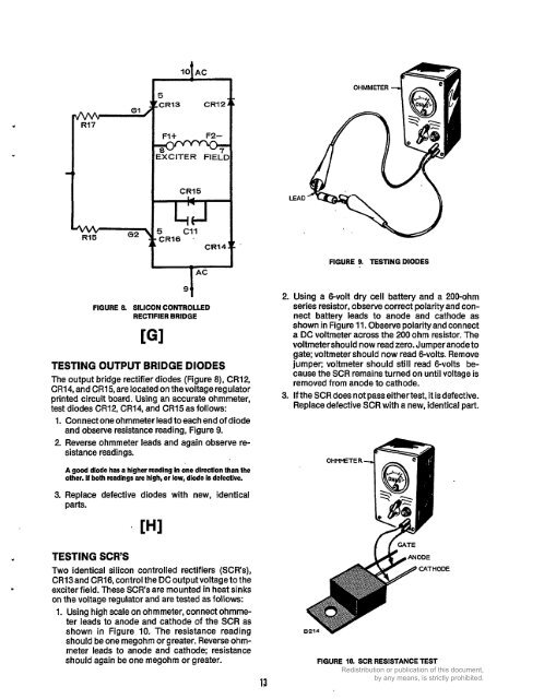
1. Connect one ohmmeter lead to each end of diode<br />
and observe resistance reading, Figure 9.<br />
2. Reverse ohmmeter leads and again observe resistance<br />
readings.<br />
A good diode has a higher reading In one direction than the<br />
other. If both readings are high, or low, diode is defective.<br />
3. Replace defective diodes with new, identical<br />
parts.<br />
TESTING SCR'S<br />
Two identical silicon controlled rectifiers (SCR's),<br />
CR13and CR16, control the DC output voltage to the<br />
exciter field. These SCR's are mounted in heat sinks<br />
on the voltage regulator and are tested as follows:<br />
1. Using high scale on ohmmeter, connect ohmme-<br />
ter leads to anode and cathode of the SCR as<br />
shown in Figure 10. The resistance reading<br />
should be one megohm or greater. Reverse ohm-<br />
meter leads to anode and cathode; resistance<br />
should again be one megohm or greater.<br />
8<br />
13<br />
FIGURE 9. TESTING DIODES<br />
2. Using a &volt dry cell battery and a 200-ohm<br />
series resistor, observe correct polarity and con-<br />
nect battery leads to anode and cathode as<br />
shown in Figure 11. Observe polarityand connect<br />
a DC voltmeter across the 200 ohm resistor. The<br />
voltmeter should now read zero. Jumper anode to<br />
gate: voltmeter should now read &volts. Remove<br />
jumper; voltmeter should still read &volts be-<br />
cause the SCR remains turned on until voltage is<br />
removed from anode to cathode.<br />
3. If the SCR does not pass eithertest, it is defective.<br />
Replace defective SCR with a new, identical part.<br />
OHMMETER<br />
FIGURE 10. SCR RESISTANCE TEST


