

Caution: This document contains mixed page sizes ... - Igor Chudov
Caution: This document contains mixed page sizes ... - Igor Chudov
Caution: This document contains mixed page sizes ... - Igor Chudov

Create successful ePaper yourself
Turn your PDF publications into a flip-book with our unique Google optimized e-Paper software.
generator adapter. The brushless exciter stator<br />
mounts in the end bell while the exciter rotor and its<br />
rotating rectifier assemblies mount on the generator<br />
rotor shaft.<br />
All generators have four wires extending from the<br />
stator housing in addition to the AC output leads,<br />
Figure 2. Lead B2 is from the battery charge winding<br />
and connects to terminal 7 of the engine control.<br />
Lead F1+ and F2- are from the exciter field winding<br />
and are connected to the output terminals of the<br />
voltage regulator. Leads 1 and Pare connected to the<br />
stator windings and provide reference voltage and<br />
input powerto thevoltage regulator. These four leads<br />
are connected at the factory.<br />
Figure 2 is a composite illustration showing four output leads for<br />
single-phase units, l2output leadsfor *phase broad range units,<br />
and four output leadsforcode 9x3-phase 347l600volt generators.<br />
CHARGING<br />
BAlTERY<br />
RESISTOR CHARGING<br />
TO VOLTAGE 1<br />
REGULATOR<br />
F 2 - n<br />
r 7 7<br />
TO<br />
ENGINE<br />
-CONTROL<br />
. FIGURE 2 SINGLE AND THREE PHASE GENERATOR<br />
SCHEMATIC (COMPOSITE)<br />
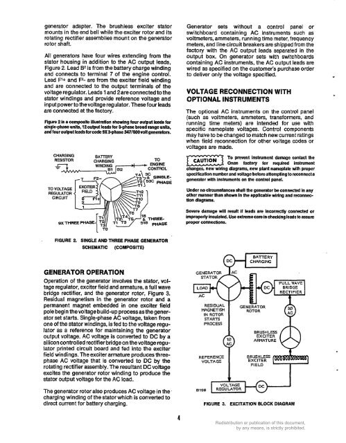
GENERATOR OPERATION<br />
Operation of the generator involves the stator, vol-<br />
tage regulator, exciter field and armature, a full wave<br />
bridge rectifier, and the generator rotor, Figure 3.<br />
Residual magnetism in the generator rotor and a<br />
permanent magnet embedded in one exciter field<br />
pole begin thevoltage build-up processasthe gener-<br />
ator set starts. Single-phase AC voltage, taken from<br />
one of the stator windings, is fed to the voltage regu-<br />
lator as a reference for maintaining the generator<br />
output voltage. AC voltage is converted to DC by a<br />
silicon controlled rectifier bridge on the voltage regu-<br />
lator printed circuit board and fed into the exciter<br />
field windings. The exciter armature produces three-<br />
phase AC voltage that is converted to DC by the<br />
rotating rectifier assembly. The resultant DC voltage<br />
excites the generator rotor winding to produce the<br />
stator output voltage for the AC load.<br />
The generator rotor also produces AC voltage in the '<br />
charging winding of the stator which is converted to<br />
direct current for battery charging.<br />
4<br />
Generator sets without a control panel or<br />
switchboard containing AC instruments such as<br />
voltmeters, ammeters, running time meter, frequency<br />
meters, and line circuit breakers are shipped from the<br />
factory with the AC output leads separated in the<br />
output box. On generator sets with switchboards<br />
containing AC instruments, the AC output leads are<br />
wired as specified on the customer's purchase order<br />
to deliver only the voltage specified. -<br />
VOLTAGE RECONNECTION WITH<br />
OPTIONAL INSTRUMENTS<br />
The optional AC instruments on the control panel<br />
(such as voltmeters, ammeters, transformers, and<br />
running time meters) are intended for use with<br />
specific nameplate voltages. Control components<br />
may have to be changed to match new current ratings<br />
when field reconnection for other voltage codes or<br />
voltages are made.<br />
a To prevent instrument damage contact the<br />
CAUT,ON<br />
Onan factory for required instrument<br />
changes, new wiring diagrams, new plant nameplate with proper<br />
specification number and voltagebefore attempting to reconnect a<br />
generator with instruments on the control panel.<br />
Under no circumstances shall the generator be connected in any<br />
other mannerthan shown in the applicable wiring and reconnec-<br />
tion diagrams.<br />
Severe damage will result if leads are incorrectly connected or<br />
improperly insulated. Use extreme care in checking leads to assure<br />
proper connections.<br />
I<br />
RESIDUAL .<br />
MAGNETISM<br />
IN ROTOR<br />
STARTS<br />
ROTOh<br />
REFERENCE<br />
B RUSHLESS<br />
VOLTAGE EXCITER<br />
FIELD<br />
h<br />
FULL WAVE<br />
BRIDGE<br />
RECTI FIE R<br />
FIGURE 3. EXCITATION BLOCK DIAGRAM<br />
I


