D - Timken
D - Timken D - Timken
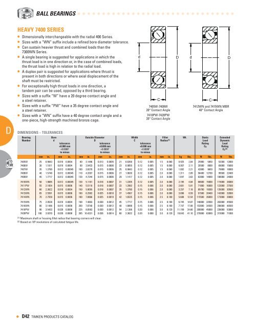
D A A A A A • BAll BeARIngS hEAvY 7 00 SERIES • Dimensionally interchangeable with the radial 400 Series. • Sizes with a “WN” suffix include a refined bore diameter tolerance. • Can sustain heavier thrust and combined loads than the 7300WN Series. • A single bearing is suggested for applications in which the thrust load is in one direction or, in the case of combined loads, the thrust load is high in relation to the radial load. • A duplex pair is suggested for applications where thrust is present in both directions or where axial displacement of the shaft must be restricted. • For exceptionally high thrust loads in one direction, a tandem pair can be used, opposed by a third bearing. • Sizes with a suffix “W” have a 20 degree contact angle and a steel retainer. • Sizes with a suffix “PW” have a 35 degree contact angle and a steel retainer. • Sizes with a “WN” suffix have a 40 degree contact angle and a one-piece, high-strength machined bronze cage. DIMENSIONS – TOLERANCES Bearing Bore Outside Diameter Width Fillet Wt. Static Extended Number d D C Radius (1) Load Dynamic tolerance tolerance tolerance Rating Load +0.000 mm +0.0000" to minus +0.000 mm +0.0000" to minus +0.000 mm +0.0000" to minus CO Rating CE ( ) mm in. mm in. mm in. mm in. mm in. mm in. mm in. kg lbs. N lbs. N lbs. 7405W 25 0.9843 0.010 0.0004 80 3.1496 0.013 0.0005 21 0.8268 0.12 0.005 1.5 0.060 0.925 2.04 25900 5850 53300 12000 7406W 30 1.1811 0.010 0.0004 90 3.5433 0.015 0.0006 23 0.9055 0.12 0.005 1.5 0.060 0.957 2.11 35500 8000 69000 15600 7407W 35 1.3780 0.012 0.00045 100 3.9370 0.015 0.0006 25 0.9843 0.12 0.005 1.5 0.060 1.002 2.21 42800 9650 79900 18000 7408W 40 1.5748 0.012 0.00045 110 4.3307 0.015 0.0006 27 1.0630 0.12 0.005 2.0 0.080 1.311 2.89 56400 12700 99500 22400 7409W 45 1.7717 0.012 0.00045 120 4.7244 0.015 0.0006 29 1.1417 0.12 0.005 2.0 0.080 1.647 3.63 62000 14000 106000 24000 7410WN 50 1.9685 0.012 0.00045 130 5.1181 0.018 0.0007 31 1.2205 0.12 0.005 2.0 0.080 2.195 4.84 66600 15000 115000 26000 7411PW 55 2.1654 0.015 0.0006 140 5.5118 0.018 0.0007 33 1.2992 0.15 0.006 2.0 0.080 2.681 5.91 71000 16000 122000 27500 7412WN 60 2.3622 0.010 0.0004 150 5.9055 0.018 0.0007 35 1.3780 0.15 0.006 2.0 0.080 3.257 7.18 85700 19300 135000 30500 7413WN 65 2.5591 0.015 0.0006 160 6.2992 0.025 0.0010 37 1.4567 0.15 0.006 2.0 0.080 3.896 8.59 91500 20400 142000 32000 7414WN 70 2.7559 0.015 0.0006 180 7.0866 0.025 0.0010 42 1.6535 0.15 0.006 2.5 0.100 5.688 12.54 115500 26000 173000 39000 7415WN 75 2.9528 0.010 0.0004 190 7.4803 0.030 0.0012 45 1.7717 0.15 0.006 2.5 0.100 6.745 14.87 148000 33500 202000 45500 7416WN 80 3.1496 0.015 0.0006 200 7.8740 0.030 0.0012 48 1.8898 0.15 0.006 2.5 0.100 7.747 17.08 153000 34500 206000 46500 7418PW 90 3.5433 0.020 0.0008 225 8.8583 0.030 0.0012 54 2.1268 0.20 0.008 3.0 0.120 11.159 24.60 200000 45000 236000 53000 7420PW 100 3.9370 0.020 0.0008 265 10.4331 0.036 0.0014 60 2.3622 0.20 0.008 3.0 0.120 18.643 41.10 279000 63000 315000 71000 (1) Maximum shaft or housing fillet radius that bearing corners will clear. (2) Based on 10 6 revolutions of calculated fatigue life. D TIMKEN PRODUCTS CATALOG d D d D C 7405W-7409W 7412WN and 7415WN MBR 20° Contact Angle 40° Contact Angle 7410PW-7420PW 35° Contact Angle C
LIGhT 00 SERIES • Features the same bores and outside diameters as the corresponding bearings in the 200 Series single-row radial type. • Double-row angular contact ball bearings meet the demand for increased axial and radial rigidity in applications where the design limits space. • Available in both Conrad and maximum capacity types. • Suffix “K” denotes Conrad (example: 5203K). • Suffix “W” or no suffix denotes maximum capacity type (example: 5212W, 5213). • Please note: these double-row series bearings are not prelubricated. DIMENSIONS – TOLERANCES Radial and Angular Contact Ball Bearings Bearing Bore Outside Diameter Width Fillet Contact Wt. Static Extended Number d D C Radius (1) Angle Load Dynamic tolerance tolerance Rating Load +0.000 mm +0.0000" to minus +0.000 mm +0.0000" +0.00 mm, -0.1 mm to minus +0.000", -0.005" Co Rating CE ( ) mm in. mm in. mm in. mm in. mm in. in. mm in. kg lbs. N lbs. N lbs. 5200K (2) 10 0.3937 0.008 0.0003 30 1.1811 0.009 0.00035 14.27 0.562 9 ⁄16 0.6 0.024 20° 0.054 0.12 5060 1140 10600 2400 5201K (2) 12 0.4724 0.008 0.0003 32 1.2598 0.012 0.00045 15.88 0.625 5 ⁄8 0.6 0.024 20° 0.068 0.15 4700 1060 9060 2040 5202K (2) 15 0.5906 0.008 0.0003 35 1.3780 0.012 0.00045 15.88 0.625 5 ⁄8 0.6 0.024 20° 0.073 0.16 7100 1600 13500 3050 5203K (2) 17 0.6693 0.008 0.0003 40 1.5748 0.012 0.00045 17.48 0.688 11 ⁄16 0.6 0.024 20° 0.104 0.23 9200 2080 16800 3800 5204K (2) 20 0.7874 0.010 0.0004 47 1.8504 0.012 0.00045 20.62 0.812 13 ⁄16 1.0 0.039 20° 0.163 0.36 12600 2850 22600 5100 5205K (2) 25 0.9843 0.010 0.0004 52 2.0472 0.013 0.0005 20.62 0.812 13 ⁄16 1.0 0.039 20° 0.186 0.41 15100 3400 24800 5600 5206K 30 1.1811 0.010 0.0004 62 2.4409 0.013 0.0005 23.83 0.938 15 ⁄16 1.0 0.039 20° 0.295 0.65 21700 4900 34600 7800 5206W 30 1.1811 0.010 0.0004 62 2.4409 0.013 0.0005 23.83 0.938 15 ⁄16 1.0 0.039 30° 0.295 0.65 27000 6100 39000 8800 5207K 35 1.3780 0.012 0.00047 72 2.8346 0.013 0.0005 26.97 1.062 1 1 ⁄16 1.0 0.039 20° 0.481 1.06 29000 6550 45000 10200 5207W 35 1.3780 0.012 0.00047 72 2.8346 0.013 0.0005 26.97 1.062 1 1 ⁄16 1.0 0.039 30° 0.481 1.06 36800 8300 51500 11600 5208K 40 1.5748 0.012 0.00047 80 3.1496 0.013 0.0005 30.17 1.188 1 3 ⁄16 1.0 0.039 20° 0.566 1.32 33900 7650 51500 11600 5208W 40 1.5748 0.012 0.00047 80 3.1496 0.013 0.0005 30.17 1.188 1 3 ⁄16 1.0 0.039 30° 0.599 1.32 47000 10600 62000 14000 5209K 45 1.7717 0.012 0.00047 85 3.3456 0.015 0.0006 30.17 1.188 1 3 ⁄16 1.0 0.039 20° 0.699 1.54 39000 8800 57000 12900 5209W 45 1.7717 0.012 0.00047 85 3.3456 0.015 0.0006 30.17 1.188 1 3 ⁄16 1.0 0.039 30° 0.699 1.54 51500 11600 64800 14600 5210K 50 1.9685 0.012 0.00047 90 3.5433 0.015 0.0006 30.17 1.188 1 3 ⁄16 1.0 0.039 20° 0.753 1.66 44400 10000 62000 14000 5210W 50 1.9685 0.012 0.00047 90 3.5433 0.015 0.0006 30.17 1.188 1 3 ⁄16 1.0 0.039 30° 0.753 1.66 56000 12700 66600 15000 5211K 55 2.1654 0.015 0.0006 100 3.9370 0.015 0.0006 33.32 1.312 (4) 1 5 ⁄16 1.5 0.059 20° 1.039 2.29 71000 12700 76000 17300 5211W 55 2.1654 0.015 0.0006 100 3.9370 0.015 0.0006 33.32 1.312 (4) 1 5 ⁄16 1.5 0.059 30° 1.039 2.29 62000 16000 84000 19000 5212K 60 2.3622 0.015 0.0006 110 4.3307 0.015 0.0006 36.53 1.438 (4) 1 7 ⁄16 1.5 0.059 20° 1.388 3.06 88800 14000 85000 19300 5212W 60 2.3622 0.015 0.0006 110 4.3307 0.015 0.0006 36.53 1.438 (4) 1 7 ⁄16 1.5 0.059 30° 1.388 3.06 72000 20000 103000 23800 5213K 65 2.5591 0.015 0.0006 120 4.7244 0.015 0.0006 38.10 1.500 (4) 1 1 ⁄2 1.5 0.059 20° 1.923 4.24 76800 17300 101000 22800 5213 (3) 65 2.5591 0.015 0.0006 120 4.7244 0.015 0.0006 38.10 1.500 (4) 1 1 ⁄2 1.5 0.059 30° 1.923 4.24 92000 20800 99500 22400 5214K 70 2.7559 0.015 0.0006 125 4.9213 0.018 0.0007 39.67 1.562 (4) 1 9 ⁄16 1.5 0.059 20° 2.096 4.62 84000 19000 108000 24500 5214 (3) 70 2.7559 0.015 0.0006 125 4.9213 0.018 0.0007 39.67 1.562 (4) 1 9 ⁄16 1.5 0.059 30° 2.096 4.62 126000 28500 139000 31500 5215K 75 2.9528 0.015 0.0006 130 5.1181 0.018 0.0007 41.28 1.625 (4) 1 5 ⁄8 1.5 0.059 20° 2.336 5.15 85700 19300 108000 24500 5215 (3) 75 2.9528 0.015 0.0006 130 5.1181 0.018 0.0007 41.28 1.625 (4) 1 5 ⁄8 1.5 0.059 30° 2.336 5.15 137000 31000 144000 32500 5216 (3) 80 3.1496 0.015 0.0006 140 5.5118 0.018 0.0007 44.45 1.750 (4) 1 3 ⁄4 2.0 0.079 30° 2.867 6.32 162000 36500 168000 38000 5217 (3) 85 3.3465 0.020 0.0008 150 5.9055 0.018 0.0007 49.23 1.938 (5) 1 15 ⁄16 2.0 0.079 30° 3.629 8.00 177000 40000 188000 42500 5218W 90 3.5433 0.020 0.0008 160 6.2992 0.025 0.0010 52.37 2.062 (5) 2 1 ⁄16 2.0 0.079 20° 4.518 9.96 191000 43000 202000 45500 5219 (3) 95 3.7402 0.020 0.0008 170 6.6929 0.025 0.0010 55.58 2.188 (5) 2 3 ⁄16 2.0 0.079 30° 5.411 11.93 235000 53000 244000 55000 5220W 100 3.9370 0.020 0.0008 180 7.0866 0.025 0.0010 60.32 2.375 (5) 2 3 ⁄8 2.0 0.079 20° 6.541 14.42 253000 57000 259000 58500 5221W 105 4.1339 0.020 0.0008 190 7.4803 0.030 0.0012 65.10 2.563 (5) 2 9 ⁄16 2.0 0.079 20° 7.537 16.60 301000 67600 300000 67500 5222 (3) 110 4.3307 0.020 0.0008 200 7.8740 0.030 0.0012 69.85 2.750 (5) 2 3 ⁄4 2.0 0.079 30° 9.503 20.95 339000 76500 326000 73500 (1) Maximum shaft or housing fillet radius that bearing corners will clear. (2) Sizes have PRB molded nylon retainers. (3) These sizes have contact angle converging inside the bearing. (4) Width tolerance is +.00 mm to -.15 mm (+.000 to -.006"). (5) Width tolerance is +.00 mm to -.20 mm (+.000 to -.008"). (6) Based on 10 6 revolutions of calculated fatigue life. Note: See page D45 for Shield and Snap Ring Combinations. d C D TIMKEN PRODUCTS CATALOG D • AD A A A A A
- Page 1 and 2: D D BALL BEARINGS BALL BEARINGS Rad
- Page 3 and 4: RADIAL AND ANGULAR CONTACT BEARINGS
- Page 5 and 6: Radial and Angular Contact Ball Bea
- Page 7 and 8: XLS AND EXTRA LARGE 100 SERIES Bear
- Page 9 and 10: EXTRA SMALL 0 METRIC SERIES MEChANI
- Page 11 and 12: FLANGED SERIES CYLINDRICAL O.D. •
- Page 13 and 14: SPECIAL BEARINGS • Pulley, guide
- Page 15 and 16: EXTRA LIGhT 100K SERIES (continued)
- Page 17 and 18: ShIELDS, SEALS AND SNAP RING COMBIN
- Page 19 and 20: Listed in the table below are Timke
- Page 21 and 22: d E C B B1 K Radial and Angular Con
- Page 23 and 24: LIGhT, WIDE TYPE W 00PP SERIES W 00
- Page 25 and 26: ShIELDS, SEALS AND SNAP RING COMBIN
- Page 27 and 28: Listed in the table below are Timke
- Page 29 and 30: C exterior shroud cap. d D d • Pr
- Page 31 and 32: TRI-PLY SEAL SERIES RELUBRICATABLE
- Page 33 and 34: hEX BORE BEARINGS • Designed to b
- Page 35 and 36: FARM RADIAL SPECIALS (continued) BE
- Page 37 and 38: SPECIAL BEARINGS 200KRR3 J202KRR8 2
- Page 39 and 40: BIh SERIES - MAXIMUM CAPACITY TYPE
- Page 41 and 42: 7000WN PRODUCT FAMILY INTRODUCTION
- Page 43: MEDIUM 7 00WN SERIES • Dimensiona
- Page 47 and 48: ShIELD AND SNAP RING COMBINATIONS 0
- Page 49 and 50: WIDE INNER RING Wide Inner Ring Ove
- Page 51 and 52: Wide Inner Ring Ball Bearings Page
- Page 53 and 54: RA-DD SERIES BEARINGS The RA-DD Ser
- Page 55 and 56: KR, KRR, KRRB INDUSTRIAL SERIES NON
- Page 57 and 58: GN-KRRB HEAVy SERIES RELUBRICATABLE
- Page 59 and 60: GRA-RR, GRA-RRB STANDARD SERIES REL
- Page 61 and 62: GyA-RR, GyA-RRB STANDARD SERIES REL
- Page 63 and 64: KL, KLB, KLL, KLLB SPECIAL SERIES N
- Page 65 and 66: KLLG SPECIAL SERIES WITH WIRELOC
- Page 67 and 68: Tri-Ply Seal Industrial Series B 1
- Page 69 and 70: Gy-KRRB SETSCREW INDUSTRIAL SERIES
- Page 71 and 72: ER INDUSTRIAL SERIES RELUBRICATABLE
- Page 73 and 74: SMN HEAVy SERIES A AND B TyPES/MUOA
- Page 75 and 76: SMN-S HEAVy SERIES • Construction
- Page 77 and 78: HOUSED UNITS Housed Units Overview:
- Page 79 and 80: Wide Inner Ring Ball Bearings House
- Page 81 and 82: TIMKEN SELF-LOCKING COLLAR INSTALLA
- Page 83 and 84: TIMKEN SURvIvOR NT SERIES Timken S
- Page 85 and 86: YAK INDUSTRIAL SERIES SETSCREW UNIT
- Page 87 and 88: RAS, TAS, LAS INDUSTRIAL SERIES •
- Page 89 and 90: YAS INDUSTRIAL SERIES SETSCREW UNIT
- Page 91 and 92: SAS STANDARD SERIES • The SAS is
- Page 93 and 94: RAKHL EXPANSION SERIES • Designed
D<br />
A<br />
A<br />
A<br />
A<br />
A<br />
•<br />
BAll BeARIngS<br />
hEAvY 7 00 SERIES<br />
• Dimensionally interchangeable with the radial 400 Series.<br />
• Sizes with a “WN” suffix include a refined bore diameter tolerance.<br />
• Can sustain heavier thrust and combined loads than the<br />
7300WN Series.<br />
• A single bearing is suggested for applications in which the<br />
thrust load is in one direction or, in the case of combined loads,<br />
the thrust load is high in relation to the radial load.<br />
• A duplex pair is suggested for applications where thrust is<br />
present in both directions or where axial displacement of the<br />
shaft must be restricted.<br />
• For exceptionally high thrust loads in one direction, a<br />
tandem pair can be used, opposed by a third bearing.<br />
• Sizes with a suffix “W” have a 20 degree contact angle and<br />
a steel retainer.<br />
• Sizes with a suffix “PW” have a 35 degree contact angle and<br />
a steel retainer.<br />
• Sizes with a “WN” suffix have a 40 degree contact angle and a<br />
one-piece, high-strength machined bronze cage.<br />
DIMENSIONS – TOLERANCES<br />
Bearing Bore Outside Diameter Width Fillet Wt. Static Extended<br />
Number d D C Radius (1) Load Dynamic<br />
tolerance tolerance tolerance Rating Load<br />
+0.000 mm<br />
+0.0000"<br />
to minus<br />
+0.000 mm<br />
+0.0000"<br />
to minus<br />
+0.000 mm<br />
+0.0000"<br />
to minus<br />
CO Rating<br />
CE<br />
( )<br />
mm in. mm in. mm in. mm in. mm in. mm in. mm in. kg lbs. N lbs. N lbs.<br />
7405W 25 0.9843 0.010 0.0004 80 3.1496 0.013 0.0005 21 0.8268 0.12 0.005 1.5 0.060 0.925 2.04 25900 5850 53300 12000<br />
7406W 30 1.1811 0.010 0.0004 90 3.5433 0.015 0.0006 23 0.9055 0.12 0.005 1.5 0.060 0.957 2.11 35500 8000 69000 15600<br />
7407W 35 1.3780 0.012 0.00045 100 3.9370 0.015 0.0006 25 0.9843 0.12 0.005 1.5 0.060 1.002 2.21 42800 9650 79900 18000<br />
7408W 40 1.5748 0.012 0.00045 110 4.3307 0.015 0.0006 27 1.0630 0.12 0.005 2.0 0.080 1.311 2.89 56400 12700 99500 22400<br />
7409W 45 1.7717 0.012 0.00045 120 4.7244 0.015 0.0006 29 1.1417 0.12 0.005 2.0 0.080 1.647 3.63 62000 14000 106000 24000<br />
7410WN 50 1.9685 0.012 0.00045 130 5.1181 0.018 0.0007 31 1.2205 0.12 0.005 2.0 0.080 2.195 4.84 66600 15000 115000 26000<br />
7411PW 55 2.1654 0.015 0.0006 140 5.5118 0.018 0.0007 33 1.2992 0.15 0.006 2.0 0.080 2.681 5.91 71000 16000 122000 27500<br />
7412WN 60 2.3622 0.010 0.0004 150 5.9055 0.018 0.0007 35 1.3780 0.15 0.006 2.0 0.080 3.257 7.18 85700 19300 135000 30500<br />
7413WN 65 2.5591 0.015 0.0006 160 6.2992 0.025 0.0010 37 1.4567 0.15 0.006 2.0 0.080 3.896 8.59 91500 20400 142000 32000<br />
7414WN 70 2.7559 0.015 0.0006 180 7.0866 0.025 0.0010 42 1.6535 0.15 0.006 2.5 0.100 5.688 12.54 115500 26000 173000 39000<br />
7415WN 75 2.9528 0.010 0.0004 190 7.4803 0.030 0.0012 45 1.7717 0.15 0.006 2.5 0.100 6.745 14.87 148000 33500 202000 45500<br />
7416WN 80 3.1496 0.015 0.0006 200 7.8740 0.030 0.0012 48 1.8898 0.15 0.006 2.5 0.100 7.747 17.08 153000 34500 206000 46500<br />
7418PW 90 3.5433 0.020 0.0008 225 8.8583 0.030 0.0012 54 2.1268 0.20 0.008 3.0 0.120 11.159 24.60 200000 45000 236000 53000<br />
7420PW 100 3.9370 0.020 0.0008 265 10.4331 0.036 0.0014 60 2.3622 0.20 0.008 3.0 0.120 18.643 41.10 279000 63000 315000 71000<br />
(1) Maximum shaft or housing fillet radius that bearing corners will clear.<br />
(2) Based on 10 6 revolutions of calculated fatigue life.<br />
D TIMKEN PRODUCTS CATALOG<br />
d D d<br />
D<br />
C<br />
7405W-7409W 7412WN and 7415WN MBR<br />
20° Contact Angle 40° Contact Angle<br />
7410PW-7420PW<br />
35° Contact Angle<br />
C


