D - Timken
D - Timken D - Timken
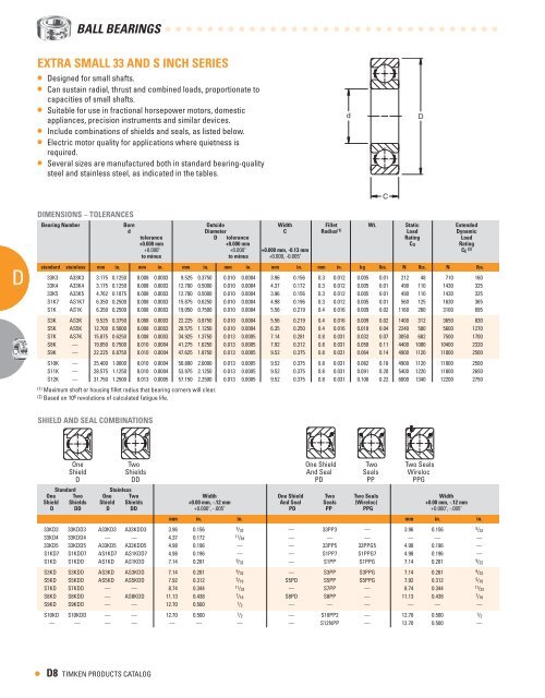
D A A A A A • BAll BeARIngS EXTRA SMALL AND S INCh SERIES • Designed for small shafts. • Can sustain radial, thrust and combined loads, proportionate to capacities of small shafts. • Suitable for use in fractional horsepower motors, domestic appliances, precision instruments and similar devices. • Include combinations of shields and seals, as listed below. • Electric motor quality for applications where quietness is required. • Several sizes are manufactured both in standard bearing-quality steel and stainless steel, as indicated in the tables. DIMENSIONS – TOLERANCES Bearing Number Bore Outside Width Fillet Wt. Static Extended d Diameter C Radius (1) Load Dynamic tolerance D tolerance Rating Load +0.000 mm +0.000" to minus +0.000 mm +0.000" to minus +0.000 mm, -0.1 mm +0.000, -0.005" CO Rating CE ( ) standard stainless mm in. mm in. mm in. mm in. mm in. mm in. kg lbs. N lbs. N lbs. 33K3 A33K3 3.175 0.1250 0.008 0.0003 9.525 0.3750 0.010 0.0004 3.96 0.156 0.3 0.012 0.005 0.01 212 48 710 160 33K4 A33K4 3.175 0.1250 0.008 0.0003 12.700 0.5000 0.010 0.0004 4.37 0.172 0.3 0.012 0.005 0.01 490 110 1430 325 33K5 A33K5 4.762 0.1875 0.008 0.0003 12.700 0.5000 0.010 0.0004 3.96 0.156 0.3 0.012 0.005 0.01 490 110 1430 325 S1K7 AS1K7 6.350 0.2500 0.008 0.0003 15.875 0.6250 0.010 0.0004 4.98 0.196 0.3 0.012 0.005 0.01 560 125 1630 365 S1K AS1K 6.350 0.2500 0.008 0.0003 19.050 0.7500 0.010 0.0004 5.56 0.219 0.4 0.016 0.009 0.02 1160 260 3100 695 S3K AS3K 9.525 0.3750 0.008 0.0003 22.225 0.8750 0.010 0.0004 5.56 0.219 0.4 0.016 0.009 0.02 1400 312 3650 830 S5K AS5K 12.700 0.5000 0.008 0.0003 28.575 1.1250 0.010 0.0004 6.35 0.250 0.4 0.016 0.018 0.04 2240 500 5600 1270 S7K AS7K 15.875 0.6250 0.008 0.0003 34.925 1.3750 0.013 0.0005 7.14 0.281 0.8 0.031 0.032 0.07 3050 682 7500 1700 S8K — 19.050 0.7500 0.010 0.0004 41.275 1.6250 0.013 0.0005 7.92 0.312 0.8 0.031 0.050 0.11 4400 1000 10400 2320 S9K — 22.225 0.8750 0.010 0.0004 47.625 1.8750 0.013 0.0005 9.52 0.375 0.8 0.031 0.064 0.14 4900 1120 11000 2500 S10K — 25.400 1.0000 0.010 0.0004 50.800 2.0000 0.013 0.0005 9.52 0.375 0.8 0.031 0.082 0.18 4900 1120 11000 2500 S11K — 28.575 1.1250 0.010 0.0004 53.975 2.1250 0.013 0.0005 9.52 0.375 0.8 0.031 0.091 0.20 5400 1220 11800 2650 S12K — 31.750 1.2500 0.013 0.0005 57.150 2.2500 0.013 0.0005 9.52 0.375 0.8 0.031 0.100 0.22 6000 1340 12200 2750 (1) Maximum shaft or housing fillet radius that bearing corners will clear. (2) Based on 10 6 revolutions of calculated fatigue life. ShIELD AND SEAL COMBINATIONS One One Shield Shield Two Two Shields One One Shield Shield And And Seal Seal Two Two Seals Seals Two Two Seals Seals WIRELOC Wireloc WIRELOC D D DD PD PD PP PP PPG PPG One Standard One Shield Two Two Stainless One Shields Two Width One Shield One And Shield Seal Two Two Seals Two Seals Two Seals WIRELOC Width Shield D Shields Shield DD Shields +0.00 mm, -.1 mm And Seal PD Seals PP (Wireloc) PPG +0.00 mm, -.1 mm D DD D DD +0.000", -.005" PD PP PPG +0.000", -.005" D8 TIMKEN PRODUCTS CATALOG mm in. in. mm in. in. 33KD3 33KDD3 A33KD3 A33KDD3 3.96 0.156 5 /32 — 33PP3 — 3.96 0.156 5 /32 33KD4 33KDD4 — — 4.37 0.172 11 /64 — — — — — — 33KD5 33KDD5 A33KD5 A33KDD5 4.98 0.196 — — 33PP5 33PPG5 4.98 0.196 — S1KD7 S1KDD7 AS1KD7 AS1KDD7 4.98 0.196 — — S1PP7 S1PPG7 4.98 0.196 — S1KD S1KDD AS1KD AS1KDD 7.14 0.281 9 /32 — S1PP S1PPG 7.14 0.281 9 /32 S3KD S3KDD AS3KD AS3KDD 7.14 0.281 9 /32 — S3PP S3PPG 7.14 0.281 9 /32 S5KD S5KDD AS5KD AS5KDD 7.92 0.312 5 /16 S5PD S5PP S5PPG 7.92 0.312 5 /16 S7KD S7KDD — — 8.74 0.344 11 /32 — S7PP — 8.74 0.344 11 /32 S8KD S8KDD — AS8KDD 11.13 0.438 7 /16 S8PD S8PP — 11.13 0.438 7 /16 S9KD S9KDD — — 12.70 0.500 1 /2 — — — — — — S10KD S10KDD — — 12.70 0.500 1 /2 — S10PP2 — 12.70 0.500 1 /2 — — — — — — — — S12NPP — 12.70 0.500 — d d C C D D
FLANGED SERIES CYLINDRICAL O.D. • Four sizes offered in flanged construction. • Integral shoulders for mounting in through-bored housings. • Straight outside diameters. • Interchangeable with corresponding unflanged sizes. • Available with double shields. • Electric motor quality for applications where quietness is required. DIMENSIONS – TOLERANCES TAPERED O.D. • F Flanged series has shoulders integral with the bearings for mounting in through-bored housings. • Used where compactness is essential or where it is not desirable to machine housing shoulders. • All sizes in series have tapered outside diameters and are available with double shields. • Suitable applications include precision instruments, packaging machinery and motion picture projectors. • Several sizes in the series are manufactured in both standard bearing-quality, chromium-alloy, high-carbon steel and stainless steel (stainless steel specified by suffix “A”). • Electric motor quality where quietness is required. Radial and Angular Contact Ball Bearings C C Open Type Shielded Type Bearing Number Bore Outside Width Inner Ring Flange Shielded Type Wt. Static Extended d Diameter C Shoulder Overall Load Dynamic chamfer D Width Rating Load J x ° A CO Rating +0.000 mm -0.008 mm +0. mm -0.00 mm +0.000 mm -0.010 mm +0.00 mm -0.1 mm +0.1 mm -0.0 mm E +0.00 mm -0.1 mm CE ( ) +0.0000” +0.010” +0.000” +0.000” h +0.005” ±0.0 mm +0.000” h open shielded* -0.0003” -0.000” -0.0004" -0.005” Min. -0.002” ±0.002” -0.005” Min. mm in. mm in. mm in. mm in. mm in. mm in. mm in. mm in. mm in. kg lbs. N lbs. N lbs. F33K3 F33KDD3 3.175 0.1250 0.30 0.012 9.525 0.3750 3.96 0.156 5.13 0.202 11.18 0.440 0.76 0.030 3.96 0.156 4.65 0.183 0.005 0.01 212 48 710 160 F33K5 F33KDD5 4.762 0.1875 0.30 0.012 12.700 0.5000 3.96 0.156 6.86 0.270 14.35 0.565 1.07 0.042 4.98 0.196 6.30 0.248 0.005 0.01 490 110 1430 325 FS1K7 FS1KDD7 (1) 6.350 0.2500 0.30 0.012 15.875 0.6250 4.98 0.196 8.86 0.349 17.53 0.690 1.07 0.042 4.98 0.196 8.43 0.332 0.005 0.01 560 125 1630 365 FS3K FS3KDD (1) 9.525 0.3750 0.41 0.016 22.225 0.8750 5.56 0.219 13.13 0.517 24.61 0.969 1.57 0.062 7.14 0.281 12.06 0.475 0.009 0.02 1400 310 3650 830 (1) Also available in stainless steel. To specify, add prefix "A" before bearing number. (2) Based on 10 6 revolutions of calculated fatigue life. * Also available with two contact seals. To specify, replace "KDD" in part number with "PP". DIMENSIONS – TOLERANCES C C Open Type Shielded Type Bearing Number Bore Outside Ring Widths Flange Wt. Static Extended d Diameter Inner Outer Load Dynamic chamfer D Width Rating Load J x ° Inner C A CO CE ( ) +0.008 mm +0.0 mm +0.000 mm Width Project h ( ) +.00 mm +0.1 mm -0.00 mm -.00 mm -0.10 mm B F -0.10 mm Taper -0.0 mm E +0.0003” +0.010” +0.000” ±0. mm ±0.1 mm +0.000" Per +0.005” ±0.0 mm open shielded -0.0000” -0.000” -0.0004" ±0.010" -0.005” Min. -0.004” Foot -0.002” ±0.002" mm in. mm in. mm in. mm in. mm in. mm in. mm in. mm in. mm in. mm in. kg lbs. N lbs. N lbs. F2 (1) — 4.762 0.1875 0.25 0.010 11.130 0.4382 4.80 0.189 0.41 0.016 6.93 0.273 4.14 0.163 2.03 0.080 12.70 0.500 1.07 0.042 0.005 0.01 465 106 1160 260 — F2DD-2 3.175 0.1250 0.25 0.010 9.534 0.3757 4.77 0.188 0.38 0.015 4.60 0.181 4.14 0.163 1.90 0.075 11.13 0.438 0.94 0.037 0.005 0.01 212 48 710 160 F3 — 4.762 0.1875 0.25 0.010 14.305 0.5632 5.54 0.218 0.38 0.015 6.93 0.273 4.95 0.195 2.03 0.080 15.88 0.625 1.07 0.042 0.005 0.01 490 110 1430 325 — F3DD 4.762 0.1875 0.25 0.010 14.305 0.5632 6.35 0.250 0.38 0.015 6.22 0.245 5.74 0.226 1.73 0.068 15.88 0.625 1.07 0.042 0.005 0.01 490 110 1430 325 F4 F4DD 6.350 0.2500 0.25 0.010 15.893 0.6257 6.35 0.250 0.38 0.015 8.41 0.331 5.74 0.226 1.73 0.068 17.45 0.687 1.07 0.042 0.005 0.01 560 125 1630 365 F5 F5DD (2) 7.938 0.3125 0.25 0.010 17.480 0.6882 6.35 0.250 0.38 0.015 10.41 0.410 (2) 5.74 0.226 1.73 0.068 19.05 0.750 1.07 0.042 0.005 0.01 865 196 2400 540 (1) Full type, no retainer. Not suggested for speeds over 500 RPM. (2) H dimension is 9.68 mm (.381") for F5DD. (3) Land dimension of the inner ring. (4) Based on 106 revolutions of calculated fatigue life. D D B J E E d F d H A H A D D TIMKEN PRODUCTS CATALOG D J B J E E d F d H A H A • AD A A A A A
- Page 1 and 2: D D BALL BEARINGS BALL BEARINGS Rad
- Page 3 and 4: RADIAL AND ANGULAR CONTACT BEARINGS
- Page 5 and 6: Radial and Angular Contact Ball Bea
- Page 7 and 8: XLS AND EXTRA LARGE 100 SERIES Bear
- Page 9: EXTRA SMALL 0 METRIC SERIES MEChANI
- Page 13 and 14: SPECIAL BEARINGS • Pulley, guide
- Page 15 and 16: EXTRA LIGhT 100K SERIES (continued)
- Page 17 and 18: ShIELDS, SEALS AND SNAP RING COMBIN
- Page 19 and 20: Listed in the table below are Timke
- Page 21 and 22: d E C B B1 K Radial and Angular Con
- Page 23 and 24: LIGhT, WIDE TYPE W 00PP SERIES W 00
- Page 25 and 26: ShIELDS, SEALS AND SNAP RING COMBIN
- Page 27 and 28: Listed in the table below are Timke
- Page 29 and 30: C exterior shroud cap. d D d • Pr
- Page 31 and 32: TRI-PLY SEAL SERIES RELUBRICATABLE
- Page 33 and 34: hEX BORE BEARINGS • Designed to b
- Page 35 and 36: FARM RADIAL SPECIALS (continued) BE
- Page 37 and 38: SPECIAL BEARINGS 200KRR3 J202KRR8 2
- Page 39 and 40: BIh SERIES - MAXIMUM CAPACITY TYPE
- Page 41 and 42: 7000WN PRODUCT FAMILY INTRODUCTION
- Page 43 and 44: MEDIUM 7 00WN SERIES • Dimensiona
- Page 45 and 46: LIGhT 00 SERIES • Features the sa
- Page 47 and 48: ShIELD AND SNAP RING COMBINATIONS 0
- Page 49 and 50: WIDE INNER RING Wide Inner Ring Ove
- Page 51 and 52: Wide Inner Ring Ball Bearings Page
- Page 53 and 54: RA-DD SERIES BEARINGS The RA-DD Ser
- Page 55 and 56: KR, KRR, KRRB INDUSTRIAL SERIES NON
- Page 57 and 58: GN-KRRB HEAVy SERIES RELUBRICATABLE
- Page 59 and 60: GRA-RR, GRA-RRB STANDARD SERIES REL
D<br />
A<br />
A<br />
A<br />
A<br />
A<br />
•<br />
BAll BeARIngS<br />
EXTRA SMALL AND S INCh SERIES<br />
• Designed for small shafts.<br />
• Can sustain radial, thrust and combined loads, proportionate to<br />
capacities of small shafts.<br />
• Suitable for use in fractional horsepower motors, domestic<br />
appliances, precision instruments and similar devices.<br />
• Include combinations of shields and seals, as listed below.<br />
• Electric motor quality for applications where quietness is<br />
required.<br />
• Several sizes are manufactured both in standard bearing-quality<br />
steel and stainless steel, as indicated in the tables.<br />
DIMENSIONS – TOLERANCES<br />
Bearing Number Bore Outside Width Fillet Wt. Static Extended<br />
d Diameter C Radius (1) Load Dynamic<br />
tolerance D tolerance Rating Load<br />
+0.000 mm<br />
+0.000"<br />
to minus<br />
+0.000 mm<br />
+0.000"<br />
to minus<br />
+0.000 mm, -0.1 mm<br />
+0.000, -0.005"<br />
CO Rating<br />
CE<br />
( )<br />
standard stainless mm in. mm in. mm in. mm in. mm in. mm in. kg lbs. N lbs. N lbs.<br />
33K3 A33K3 3.175 0.1250 0.008 0.0003 9.525 0.3750 0.010 0.0004 3.96 0.156 0.3 0.012 0.005 0.01 212 48 710 160<br />
33K4 A33K4 3.175 0.1250 0.008 0.0003 12.700 0.5000 0.010 0.0004 4.37 0.172 0.3 0.012 0.005 0.01 490 110 1430 325<br />
33K5 A33K5 4.762 0.1875 0.008 0.0003 12.700 0.5000 0.010 0.0004 3.96 0.156 0.3 0.012 0.005 0.01 490 110 1430 325<br />
S1K7 AS1K7 6.350 0.2500 0.008 0.0003 15.875 0.6250 0.010 0.0004 4.98 0.196 0.3 0.012 0.005 0.01 560 125 1630 365<br />
S1K AS1K 6.350 0.2500 0.008 0.0003 19.050 0.7500 0.010 0.0004 5.56 0.219 0.4 0.016 0.009 0.02 1160 260 3100 695<br />
S3K AS3K 9.525 0.3750 0.008 0.0003 22.225 0.8750 0.010 0.0004 5.56 0.219 0.4 0.016 0.009 0.02 1400 312 3650 830<br />
S5K AS5K 12.700 0.5000 0.008 0.0003 28.575 1.1250 0.010 0.0004 6.35 0.250 0.4 0.016 0.018 0.04 2240 500 5600 1270<br />
S7K AS7K 15.875 0.6250 0.008 0.0003 34.925 1.3750 0.013 0.0005 7.14 0.281 0.8 0.031 0.032 0.07 3050 682 7500 1700<br />
S8K — 19.050 0.7500 0.010 0.0004 41.275 1.6250 0.013 0.0005 7.92 0.312 0.8 0.031 0.050 0.11 4400 1000 10400 2320<br />
S9K — 22.225 0.8750 0.010 0.0004 47.625 1.8750 0.013 0.0005 9.52 0.375 0.8 0.031 0.064 0.14 4900 1120 11000 2500<br />
S10K — 25.400 1.0000 0.010 0.0004 50.800 2.0000 0.013 0.0005 9.52 0.375 0.8 0.031 0.082 0.18 4900 1120 11000 2500<br />
S11K — 28.575 1.1250 0.010 0.0004 53.975 2.1250 0.013 0.0005 9.52 0.375 0.8 0.031 0.091 0.20 5400 1220 11800 2650<br />
S12K — 31.750 1.2500 0.013 0.0005 57.150 2.2500 0.013 0.0005 9.52 0.375 0.8 0.031 0.100 0.22 6000 1340 12200 2750<br />
(1) Maximum shaft or housing fillet radius that bearing corners will clear.<br />
(2) Based on 10 6 revolutions of calculated fatigue life.<br />
ShIELD AND SEAL COMBINATIONS<br />
One One<br />
Shield Shield<br />
Two Two<br />
Shields<br />
One One Shield Shield<br />
And And Seal Seal<br />
Two Two<br />
Seals Seals<br />
Two Two Seals<br />
Seals<br />
WIRELOC Wireloc WIRELOC<br />
D D DD PD PD PP PP PPG<br />
PPG<br />
One Standard<br />
One Shield Two<br />
Two Stainless<br />
One Shields Two Width<br />
One Shield<br />
One And Shield Seal Two<br />
Two<br />
Seals Two Seals<br />
Two Seals<br />
WIRELOC<br />
Width<br />
Shield D Shields Shield DD Shields +0.00 mm, -.1 mm And Seal PD Seals PP (Wireloc) PPG +0.00 mm, -.1 mm<br />
D DD D DD +0.000", -.005" PD PP PPG +0.000", -.005"<br />
D8 TIMKEN PRODUCTS CATALOG<br />
mm in. in. mm in. in.<br />
33KD3 33KDD3 A33KD3 A33KDD3 3.96 0.156 5 /32 — 33PP3 — 3.96 0.156 5 /32<br />
33KD4 33KDD4 — — 4.37 0.172 11 /64 — — — — — —<br />
33KD5 33KDD5 A33KD5 A33KDD5 4.98 0.196 — — 33PP5 33PPG5 4.98 0.196 —<br />
S1KD7 S1KDD7 AS1KD7 AS1KDD7 4.98 0.196 — — S1PP7 S1PPG7 4.98 0.196 —<br />
S1KD S1KDD AS1KD AS1KDD 7.14 0.281 9 /32 — S1PP S1PPG 7.14 0.281 9 /32<br />
S3KD S3KDD AS3KD AS3KDD 7.14 0.281 9 /32 — S3PP S3PPG 7.14 0.281 9 /32<br />
S5KD S5KDD AS5KD AS5KDD 7.92 0.312 5 /16 S5PD S5PP S5PPG 7.92 0.312 5 /16<br />
S7KD S7KDD — — 8.74 0.344 11 /32 — S7PP — 8.74 0.344 11 /32<br />
S8KD S8KDD — AS8KDD 11.13 0.438 7 /16 S8PD S8PP — 11.13 0.438 7 /16<br />
S9KD S9KDD — — 12.70 0.500 1 /2 — — — — — —<br />
S10KD S10KDD — — 12.70 0.500 1 /2 — S10PP2 — 12.70 0.500 1 /2<br />
— — — — — — — — S12NPP — 12.70 0.500 —<br />
d<br />
d<br />
C<br />
C<br />
D<br />
D


