“Weather The Storm”, with Wind Driven Rain Louvers
“Weather The Storm”, with Wind Driven Rain Louvers
“Weather The Storm”, with Wind Driven Rain Louvers

You also want an ePaper? Increase the reach of your titles
YUMPU automatically turns print PDFs into web optimized ePapers that Google loves.
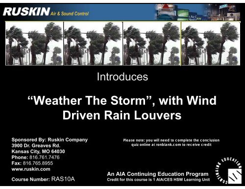
Introduces<br />
<strong>“Weather</strong> <strong>The</strong> <strong>Storm”</strong>, <strong>with</strong> <strong>Wind</strong><br />
<strong>Driven</strong> <strong>Rain</strong> <strong>Louvers</strong><br />
Sponsored By: Ruskin Company<br />
Please note: you will need to complete the conclusion<br />
quiz online at ronblank.com to receive credit<br />
3900 Dr. Greaves Rd.<br />
Kansas City, MO 64030<br />
Phone: 816.761.7476<br />
Fax: 816 816.765.8955 765 8955<br />
www.ruskin.com<br />
Course Number: RAS10A<br />
An AIA Continuing Education Program<br />
Credit for this course is 1 AIA/CES HSW Learning Unit
An American Institute of Architects (AIA)<br />
Continuing Education Program<br />
Approved Promotional Statement:<br />
Ron Blank & Associates, Inc. is a registered provider <strong>with</strong> <strong>The</strong><br />
American Institute of Architects Continuing Education System. Credit<br />
earned d upon completion l ti of f thi this program will ill bbe reported t d tto CES<br />
Records for AIA members. Certificates of Completion are available for<br />
all course participants upon completion of the course conclusion quiz<br />
<strong>with</strong> +80%. +80%<br />
Please note: you will need to complete the conclusion quiz online at<br />
ronblank.com to receive credit<br />
This program is registered <strong>with</strong> the AIA/CES for continuing<br />
professional education. As such, it does not include content that<br />
may be deemed or construed to be an approval or endorsement<br />
by the AIA or Ron Blank & Associates, Inc. of any material of<br />
construction or any method or manner of handling, using,<br />
distributing, or dealing in any material or product.
An American Institute of Architects (AIA)<br />
Continuing Education Program<br />
Course Format: This is a structured structured, web web-based, based self study course <strong>with</strong><br />
a final exam.<br />
Course Credit: 1 Health Safety & Welfare (HSW) Learning Unit (LU)<br />
CCompletion l ti CCertificate: tifi t A confirmation fi ti iis sentttto youby b email il andd you<br />
can print one upon successful completion of a course or from your<br />
RonBlank.com transcript. If you have any difficulties printing or<br />
recei receiving ing your o r Certificate please send req requests ests to carol@ronblank carol@ronblank.com com<br />
Design professionals, professionals please remember to print or save<br />
your certificate of completion after successfully completing<br />
a course conclusion quiz. Email confirmations will be sent<br />
to the email address you y have pprovided in yyour<br />
RonBlank.com account.
Copyright Materials<br />
This presentation is protected by UU.S. S and international copyright<br />
laws. Reproduction, distribution, display and use of the<br />
presentation <strong>with</strong>out written permission of<br />
© Ron Blank & Associates, Inc. 2010 and<br />
© Ruskin Company 2010 is prohibited.
Learning Objectives<br />
UUpon completion l ti of f thi this course th the ddesign i professional f i l<br />
will be able to:<br />
• Explain what a Louver is<br />
• List the terms associated <strong>with</strong> <strong>Louvers</strong><br />
• Explain how louvers are tested and what the new,<br />
more stringent test methods are<br />
• Understand how Test Methods influence louver design<br />
• Review the AMCA International’s standards for louver<br />
design and testing
<strong>Louvers</strong>!<br />
<strong>Louvers</strong> are applied universally to many building types
Form and<br />
Function<br />
<strong>Louvers</strong> are available in all types of shapes and sizes. <strong>Louvers</strong><br />
provide protection from noise and local weather conditions while<br />
providing idi outdoor d air i ffor ventilation.<br />
il i
Form and Function<br />
Because of their versatility, louvers make excellent choices for air<br />
intake and air exhaust in and out of buildings.<br />
<strong>Louvers</strong> can be located on top of buildings or at ground level.<br />
8
Form and Function<br />
<strong>Louvers</strong> can also be part of the design for mechanical rooms.<br />
9
Form and Function<br />
Or garage and warehouse ventilation.<br />
10
Form and Function<br />
<strong>Louvers</strong> can be an integral part of a building’s architecture.<br />
11
Form and Function<br />
Continuous line designs give architects the flexibility they need.<br />
12
Here is a Louvered Architectural Mechanical Room Enclosure. It is 4<br />
Form and Function<br />
stories high, and is another good example of how special architectural<br />
considerations id i can bbe executed d using i llouvers.
Form and Function<br />
Triangular shapes are very popular designs.<br />
14
Form and Function<br />
From High g Rise to<br />
Low Rise, louvers<br />
are constructed to<br />
meet the demands<br />
of the buildings<br />
atheistic and<br />
mechanical needs.
Form and Function<br />
<strong>Louvers</strong> are only limited by your imagination.<br />
16
Louver Design Considerations<br />
Wh When ddesigning i i llouvers, consideration id ti should h ld bbe given i tto<br />
the following five criteria:<br />
– Airflow<br />
– <strong>Rain</strong> Defense<br />
– Structural Integrity<br />
– Noise<br />
– Aesthetics
Airflow / Three Factors<br />
• Airflow/Volume<br />
– <strong>The</strong> measurement of the rate of airflow that passes<br />
through a louver,(measured in cfm or m3 through a louver,(measured in cfm or m s)<br />
• Pressure Drop<br />
– <strong>The</strong> resistance to airflow across an open louver<br />
( (stated t t d iin iinches h of f water/Pa) t /P )<br />
• Free Area Velocity<br />
– Rate of airflow that passes through the free area of a<br />
louver (expressed in fpm/ms)
Airflow<br />
All Three Factors Depend On <strong>The</strong> Other Other…<br />
• Airflow is the amount of air needed to perform the air<br />
handling ffunctions nctions in the bbuilding. ilding<br />
• Pressure Drop p can increase or decrease <strong>with</strong> airflow<br />
depending on the louver design.<br />
• Free Area Velocity varies as louver construction varies.<br />
Closely spaced louver blades generally have lower free<br />
areas and thus higher free area velocity for a given cfm<br />
airflow.<br />
• In Europe, Free Area Velocity is not a generally used<br />
term. Sometimes jet velocity (meaning the same thing)<br />
is used, but normally face velocity (air volume divided by<br />
the core area) is used.
<strong>Rain</strong> Defense<br />
• AMCA 500 500-LL is the current louver test standard that<br />
includes Water Penetration and <strong>Wind</strong> <strong>Driven</strong> <strong>Rain</strong> test<br />
criteria.<br />
• Water Penetration Test refers to the test method that<br />
uses “Still Air.” <strong>The</strong> velocity at which .01 ounces of<br />
water passed through the louver louver.<br />
– No European equivalent to the Water Penetration<br />
test, only the <strong>Wind</strong> <strong>Driven</strong> Test.<br />
• <strong>Wind</strong> <strong>Driven</strong> <strong>Rain</strong> Tests New to the U.S. test standard<br />
<strong>with</strong> wind pressure applied to face of louver. <strong>The</strong>y are<br />
lloosely l bbased d on EEuropean test standards d d generated d<br />
by HEVAC.<br />
• Effectiveness Class is the new water penetration<br />
classification used for <strong>Wind</strong> <strong>Driven</strong> <strong>Rain</strong>.
Structural Integrity<br />
• Wi <strong>Wind</strong>loads: dl d<br />
– American Society of Civil Engineers (ASCE)<br />
formula<br />
– British Standard BS6399 formula<br />
– Hidden or Visible supports pp<br />
– Effective <strong>Wind</strong> Speed (mph)<br />
– Louver panel size<br />
• Blade Span (Span tables)<br />
• Intermediate bracing
Structural Integrity<br />
• <strong>The</strong> ASCE formula takes into account the basic wind speed<br />
(mph), importance factor, exposure factor, height above<br />
ground and any louvers <strong>with</strong>in 10' from corners. Roughly 10%<br />
of projects have this requirement.<br />
• In the UK, the British Standard BS6399 formula is used.<br />
<strong>The</strong> UK Building Research Establishment developed a<br />
computer program on disc that calculates the wind load for you<br />
using the BS formula. <strong>The</strong> louver company is responsible for<br />
proper sizing of the louver supports. <strong>The</strong>re is no standard in<br />
the UK for louver component deflection although most<br />
manufacturers follow curtain wall standards standards.<br />
• <strong>The</strong> louver support system affects the appearance and<br />
performance p of the louver. <strong>The</strong> hidden vertical blade support pp<br />
can ad as much as 6” to the depth of the louver. <strong>Wind</strong> speeds<br />
can be determined by local authorities or by local codes. 20<br />
PSF is the design standard unless otherwise specified.<br />
• <strong>Wind</strong> speeds can be determined by local authorities or by<br />
local codes.
Noise<br />
• Sound Transmission Loss<br />
– ASTM E90-99 - Standard Test Method for Laboratory<br />
MMeasurement t of f Airborne Ai b Sound S d TTransmission i i LLoss of f<br />
Building Partitions and Elements.<br />
• Sound Transmission Classification (STC)<br />
– <strong>The</strong> STC rating is calculated in accordance <strong>with</strong> ASTM<br />
test method E413-87(1999) ( ) Standard Classification for<br />
Rating Sound Insulation.<br />
• Free Field Noise Reduction<br />
– Free Field Noise Reduction is specified in decibels and<br />
represents the louvers sound reduction in open areas.
Aesthetics<br />
• Louver Shape<br />
– Performance difference<br />
• Finish Type<br />
– To match building construction elements<br />
– Flouropolymer p y and Anodize most common<br />
– Polyester Powder Coat often used in the UK
Finish<br />
• Mill finish<br />
• Flouropolymers (Ex., Kynar, Lumiflon)<br />
– 50% and 70% PVDF<br />
– Two-Coat and Three-Coat<br />
– Mica<br />
• Anodize<br />
– Clear Anodize (204R1, 215R1)<br />
– Color Anodize (Brown and black shades)<br />
• Powdered Coats<br />
• Prime Coats
Standards and Codes<br />
With all of the design flexibility of a louver, testing to real<br />
world conditions becomes a very key task. <strong>Louvers</strong> must<br />
not only look good, good but they must perform in various<br />
elements of nature.<br />
S h t i ti k th t th l k<br />
So what organization makes sure that the louvers work as<br />
required?
AMCA International<br />
Certified Ratings g Program… g<br />
• <strong>The</strong> Certified Ratings Program was developed in response to<br />
concerns over product performance on the part of buyers buyers,<br />
specifiers, and users of air movement and air control devices.<br />
<strong>The</strong> Certified Ratings Program assures that a product line has<br />
been tested and rated in conformance <strong>with</strong> AMCA International’s<br />
International s<br />
test standards and rating requirements. A state-of-the-art testing<br />
laboratory, specifically designed and equipped <strong>with</strong> the latest<br />
equipment to carry-out carry out tests in accordance <strong>with</strong> all of AMCA<br />
International’s test standards and other international standards,<br />
supports the program.<br />
• This product performance information is valuable for making<br />
product comparisons.
AMCA International<br />
Certified Ratings g Program… g<br />
• <strong>The</strong> Certified Ratings Program requires periodic retesting (every<br />
three years) to verify performance performance. <strong>The</strong> program also allows for<br />
challenge testing, which can be initiated by competing<br />
manufacturers.<br />
• <strong>The</strong> AMCA Certified Ratings Program is far more rigorous than<br />
any program commonly used in the UK. <strong>The</strong> Building Services<br />
Research and Information Association (BSRIA) ( ) has developed p<br />
test standards on behalf of the Heating and Ventilating and Air<br />
Conditioning Manufacturers Association (HEVAC). However,<br />
there is no system <strong>with</strong> the BSRIA/HEVAC program to supply<br />
performance f information i f ti for f product d t comparisons i nor is i th there<br />
periodic re-testing.<br />
Th b tt li i th t AMCA I t ti l’ C tifi d R ti<br />
• <strong>The</strong> bottom-line is that AMCA International’s Certified Ratings<br />
Program helps people make informed decisions on purchasing<br />
and specifying air movement and air control products.
AMCA International<br />
Licensed Products…<br />
How do you know the product you specified is<br />
licensed by y AMCA International?<br />
<strong>The</strong>re are basically four ways to determine if a product is participating<br />
in AMCA International’s Certified Ratings Program. <strong>The</strong>y are:<br />
11. Visit AMCA International International’s s website at www www.amca.org amca org and click on<br />
Licensed Products. <strong>The</strong> products are displayed by manufacturers<br />
or companies and by product type.<br />
2. Check the manufacturer’s catalog. g All catalogs g containing g<br />
certified ratings are submitted to AMCA International’s technical<br />
staff for approval before publication.<br />
3. Look for the Certified Ratings Seal on the product.<br />
4. Contact AMCA International’s Certified Ratings Program<br />
Department by phone (847) 394-0150 or fax (847) 253-0088 or email<br />
crp@amca.org.<br />
<strong>The</strong>re is no system for licensed products under the British/European test<br />
method, but BSRIA Test Reports are issued as supporting documents.
AMCA<br />
Louver Test Methods<br />
<strong>The</strong>re are two distinct methods:<br />
• Water Penetration at “Still Air” conditions<br />
• <strong>Wind</strong> <strong>Driven</strong> <strong>Rain</strong> conditions<br />
Each method carries its own certification.
AMCA Standard 500-L<br />
Tests and Certifies the following:<br />
• Free Air Velocity through Louver<br />
• Pressure Drop<br />
• BBeginning i i PPoint i t of f WWater t<br />
Penetration<br />
• Water Rejecting Effectiveness<br />
• Discharge Loss<br />
• Leakage (for operable louvers)
Standard 500-L 500 L <strong>Louvers</strong><br />
Three main factors affect Free Area (FA):<br />
• Blade Angle<br />
Larger illustration on the<br />
• Blade Depth<br />
following slide<br />
• Blade Overlap<br />
Blade Angle has the most direct impact on FA<br />
Oth Other factors f t that th t affect ff t FA: FA<br />
Size of louver- i.e. A 4' X 4' louver will have a different FA than a 2' X 2'<br />
louver of the same blade configuration. g <strong>The</strong> reason for this is that the FA<br />
includes the frame; the head, sill and jambs- the smaller the louver<br />
opening the greater percentage of the overall is 'frame"- and therefore<br />
there is less area through which air can pass.<br />
Some manufacturers in US and Europe do not use the AMCA method of<br />
measuring free area and only consider the space between the blades at<br />
the front front. <strong>The</strong>refore <strong>The</strong>refore, their free areas are higher than manufacturers who<br />
follow the AMCA method.
Standard 500-L <strong>Louvers</strong><br />
FFree Area A<br />
• Measured Clearance<br />
• Minimum Inside<br />
Blade to Frame<br />
• Minimum Inside<br />
Blade to Blade
Standard 500-L <strong>Louvers</strong><br />
• Once a louver size is below 4' 4 X4' X 4 , FA is reduced<br />
drastically as a proportion of the over all louver area. <strong>The</strong><br />
frame then constitutes a greater percentage of the overall<br />
area.<br />
• <strong>The</strong> converse is also true, <strong>with</strong> louver FA increasing as<br />
the louver increases in size and the frame becomes a<br />
lesser percentage of the overall louver area.<br />
• All manufacturers publish FA data charts for unit sizes sizes. If<br />
FA is a major concern, be sure to consult the respective<br />
manufacturers data chart.<br />
• Free Area by itself should NEVER be a design criteria.<br />
<strong>The</strong> designer must also consider Pressure Drop. <strong>The</strong><br />
chart on the following slide will further explain explain.
Standard 500-L <strong>Louvers</strong><br />
Free Area Tables<br />
By Actual FA<br />
or % FA<br />
35
Standard 500-L <strong>Louvers</strong><br />
PPressure DDrop<br />
• Pressure Drop (PD) is a key design<br />
element for louvers.<br />
• <strong>The</strong> more flowing air changes<br />
direction, as when passing over a<br />
louver blade and through a louver louver,<br />
the higher the PD will be. Blade<br />
design has a direct impact on PD.<br />
Generally speaking, the more steps,<br />
nooks, crannies and drainage<br />
provisions there are on a specific<br />
blade configuration, g , the higher g the<br />
PD.<br />
Figure 5.4 test set up is for air intakes and 5.5<br />
is for air discharges or exhausts.
Standard 500-L <strong>Louvers</strong><br />
Louver specifications frequently reference FA and PD PD. This<br />
does not take into consideration the key issue of volume of<br />
air passing through an opening.<br />
Depth of a louver is a notable issue <strong>with</strong> regard to PD. A<br />
deeper louver <strong>with</strong> a tighter blade spacing configuration and<br />
less abrupt blade angle reduces PD, but the trade off is cost.<br />
A deep louver <strong>with</strong> many blades will cost more than a<br />
narrower louver <strong>with</strong> fewer blades. Gradual curved blades<br />
provide for a lower PD than abruptly changing blades.<br />
So, there is a give-and-take relationship between louver<br />
ddesign, i ddepth, h performance, f and d cost.
Standard 500-L <strong>Louvers</strong><br />
Although the concept of FA and PD makes sense sense, the prime<br />
issue of louver sizing should be "how much air do you need<br />
to move through the louver" and "what is the maximum<br />
pressure drop you can live <strong>with</strong>”.<br />
From this information a louver may be selected and sized to<br />
meet all important criteria, satisfying the mechanical<br />
engineer and the design architect. architect <strong>The</strong> mechanical engineer<br />
gets his air performance, the design architect gets his<br />
appearance and water protection.<br />
Let’s talk a little more about water protection…
Standard 500-L <strong>Louvers</strong><br />
54 5.4 Wall W llIIntake k<br />
Pressure Required to Accelerate Air and Overcome<br />
Losses due to Blockage and Entrance Conditions
Standard 500-L <strong>Louvers</strong><br />
55 5.5 Wall W llDi Discharge h<br />
Pressure Required to Accelerate Air and Overcome<br />
Losses due to Blockage and Exit Conditions
Standard 500-L <strong>Louvers</strong><br />
WWater Penetration P i or WWater Rejection R j i<br />
• Two Test Configurations<br />
• 5.6 Water Penetration for “Still Air”<br />
• 55.11 11 Water Rejection for <strong>Wind</strong> <strong>Driven</strong> <strong>Rain</strong><br />
Th <strong>The</strong> engineering i i<br />
community is very familiar<br />
<strong>with</strong> figure g 5.6. It is the<br />
standard to which most<br />
louvers are specified.<br />
<strong>The</strong> new kid on the<br />
block is 5.11
Standard 500-L <strong>Louvers</strong><br />
55.6 6 Water Penetration
Standard 500-L <strong>Louvers</strong><br />
Test Conditions<br />
• 4” per hour rain<br />
• 1250 fpm max free area velocity<br />
(approx 14 mph)<br />
• Weight of water penetration per ft2 free area @ free area velocity
Standard 500-L <strong>Louvers</strong><br />
Test Conditions<br />
• This photograph of an AMCA still<br />
air i ttest t chamber h b llets t you bbetter tt<br />
understand the test. Please note<br />
that water is released under still<br />
air i conditions. diti AAnd d cascading di<br />
down both the “building” face as<br />
well as in front of the louver.<br />
With a steady intake of up to<br />
1250 fpm, measurements are<br />
taken <strong>with</strong> regard to pressure<br />
drop and point of beginning water<br />
penetration. Using this test a<br />
louver is rated and certified.
Standard 500-L <strong>Louvers</strong><br />
Test Conditions<br />
• Remember though, that this test is administered under<br />
“l “laboratory” b t ” still till air i conditions diti and d makes k no provision i i<br />
to gauge the louver’s effectiveness when subjected to<br />
the horizontal, wind driven rain typical of a moderate to<br />
severe storm. t<br />
• Drainable blade louvers tested in accordance <strong>with</strong><br />
AMCA Still Air Tests, Tests (not the AMCA <strong>Wind</strong> <strong>Driven</strong> <strong>Rain</strong><br />
Water Penetration Test), will entrain some water when<br />
subjected to storm conditions. This style of louver<br />
performs better than the standard non non-drainable drainable styles<br />
for water penetration. Always consider the <strong>Wind</strong> <strong>Driven</strong><br />
<strong>Rain</strong> Performance designs when protection from water<br />
carryover is a must must.
MASTERSPEC – EVALUATIONS 8/93<br />
“Water-penetration testing measures the weight of water in<br />
ounces per sq. ft. of louver free area passing from the<br />
l louver’s ’ exterior t i tto th the iinterior t i at t various i air i iintake t k<br />
velocities...<br />
It is important to realize that the test is based on<br />
still air conditions and simulates the effect of falling rain and<br />
rain flowing down the wetted surface of a building over a<br />
louver…<br />
This test was backed up by the Masterspec in 1993 because it was the best<br />
the industry had to offer.
MASTERSPEC – EVALUATIONS 8/93<br />
…While this may provide accurate data for rain conditions<br />
<strong>with</strong> only fan-induced air-intake velocities velocities,<br />
no test currently exists that provides data on louver<br />
y<br />
performance during exposure to wind driven rain”
Real Life Conditions<br />
Severe Storm footage - Real life conditions. Extensive,<br />
continuous wind-driven wind driven rain rain.
Typical Drainable Louver Shape<br />
This is a typical 5 6 tested<br />
This is a typical 5.6 tested<br />
drainable louver
“Still Still Air” Air Louver in <strong>Wind</strong> <strong>Driven</strong> Test<br />
Here is the same type of typical drainable louver in a wind-<br />
driven rain test test.
Examples of Wrong Installations<br />
International Airport:<br />
Electrical service area for<br />
the Monorail system shut down/<br />
immobilized for days due to Standard louvers<br />
poor louver selection used where Storm<br />
Resistant could<br />
have been.<br />
Location and performance of the louver is critical to success of the<br />
building design.<br />
51
Louver <strong>Rain</strong> Defense<br />
• Prevents Damage<br />
– Minimizes mold in HVAC<br />
system<br />
– Critical for Generators,<br />
Production Plants<br />
RAIN<br />
– Electrical switchgear areas<br />
– Insulation in duct WIND<br />
• Protects interior finishes &<br />
contents.<br />
– Exhibition Halls, Halls<br />
Warehousing, Museums…
Louver <strong>Rain</strong> Defense<br />
• AMCA standard 500-L-99<br />
– AMCA revised its standard to include recommendations<br />
for wind driven rain testing of louvers based on HEVAC<br />
method. th d<br />
• Masterspec 2000<br />
– Includes substantial changes to the advice given when<br />
selecting louvers. <strong>Wind</strong> driven rain resistant louvers<br />
are now recommended for use.<br />
Products to meet these needs and recommendations<br />
have been developed p and are increasingly g y specified. p
Louver <strong>Rain</strong> Defense<br />
• New test methods were required to meet the demands of<br />
the building designs and prevent water intrusion.<br />
• In real-life storm conditions where <strong>Wind</strong> <strong>Driven</strong> <strong>Rain</strong> is<br />
commonplace, rainwater penetrates even the highest<br />
rated louvers tested under the AMCA still air test.<br />
• IIn response to t this thi serious i problem, bl llouver manufacturers f t<br />
introduced products specifically engineered to prevent rain<br />
entry y<br />
under storm conditions.
Louver <strong>Rain</strong> Defense<br />
• To maintain a standard of comparison <strong>with</strong>in the industry industry,<br />
AMCA expanded its testing and certification process to<br />
include the testing of louvers under moderate and severe<br />
storm conditions.<br />
• Further, in their 2000 update, Masterspec included<br />
specific recommendations for the use of “Storm Storm Resistant” Resistant<br />
louvers anywhere water entry was a concern.<br />
• Clearly, y, <strong>Wind</strong> <strong>Driven</strong> <strong>Rain</strong> and the Damage g it can cause<br />
has become a significant factor in both the design and<br />
testing of louver products.
“Still Still Air” Air vs vs. <strong>Wind</strong> <strong>Wind</strong><strong>Driven</strong><strong>Rain</strong>Tests<br />
<strong>Driven</strong> <strong>Rain</strong> Tests<br />
You can visually and descriptively compare the two tests on the<br />
following slide.<br />
Basic comparison:<br />
1. <strong>The</strong> AMCA <strong>Wind</strong> <strong>Driven</strong> <strong>Rain</strong> test records multiple data points<br />
at each of 8 ventilation rates, over as a period of 8 hours or<br />
more per test- while the AMCA still air test tests for only 15<br />
minutes to determine the beginning point of water penetration.<br />
penetration<br />
2. AMCA still air test tests to establish a point of beginning water<br />
penetration. <strong>The</strong> AMCA <strong>Wind</strong> <strong>Driven</strong> <strong>Rain</strong> test rates a louver’s<br />
effectiveness at preventing water from passing through an<br />
opening at various test conditions.<br />
3. AMCA still air test has one set of parameters to test a louver. .<br />
<strong>The</strong> AMCA <strong>Wind</strong> <strong>Driven</strong> <strong>Rain</strong> test varies the testing parameters<br />
ventilation rate and air intake velocity) to rate the louver at a<br />
variety of test points.
“Still Still Air” Air vs vs. <strong>Wind</strong> <strong>Wind</strong><strong>Driven</strong><strong>Rain</strong>Tests<br />
<strong>Driven</strong> <strong>Rain</strong> Tests
“Still Still Air” Air vs vs. <strong>Wind</strong> <strong>Wind</strong><strong>Driven</strong><strong>Rain</strong>Tests<br />
<strong>Driven</strong> <strong>Rain</strong> Tests<br />
AMCA AMCA<br />
<strong>Wind</strong> <strong>Driven</strong> <strong>Rain</strong> “Still Still Air Air”<br />
Test Duration 30 minutes (minimum) 15 minutes (minimum)<br />
Air Intake (fpm)<br />
Maximum 1250+ 1250 1250<br />
Minimum No No<br />
<strong>Wind</strong> <strong>Driven</strong> <strong>Rain</strong> Yes No<br />
<strong>Rain</strong> Fall Rate 75mm/hr (3 (3") ) 4"/hr 4/hr<br />
or 200mm/hr (8”)<br />
Static Pressure Drop Yes Yes<br />
Free Area Yes Yes<br />
Test Points Numerous 4<br />
Louver Test Size 1mx1m core or 48”x48” 48" X 48"<br />
Goal Establish louver Establish point p of<br />
effectiveness by<br />
varying test conditions penetration<br />
beginning water<br />
As you can readily discern, the <strong>Wind</strong> driven rain test is much more comprehensive<br />
and provides a more thorough evaluation of the test louver’s louver s performance <strong>with</strong><br />
regard to effectiveness against rain penetration.<br />
Here is a point by point comparison, BSRIA/HEVAC test standard doesn’t have the<br />
higher 200mm/hr (8”/hr) rain category.
Video – <strong>Wind</strong><strong>Driven</strong>Test<br />
<strong>Wind</strong> <strong>Driven</strong> Test<br />
Look at the wind driven rain test in action action.
AMCA 500-L Test- Test - Video<br />
<strong>Wind</strong> <strong>Driven</strong> <strong>Rain</strong><br />
testing at 29 mph<br />
wind velocity and 3 3”<br />
of rain per hour<br />
Water is outside<br />
where it belongs<br />
As you can see, virtually all water is denied entry to the building and is<br />
drained in a controlled manner to the sill pan, where it leaves the louver.<br />
Remember Remember, <strong>with</strong> the new test standards it is no longer adequate to<br />
specify that a manufacturer must have louvers AMCA certified in<br />
accordance <strong>with</strong> AMCA 500-L-99. You must now clarify what test criteria<br />
and tests the louvers must be tested to…<br />
Still Air or <strong>Wind</strong> <strong>Driven</strong> <strong>Rain</strong> (and if <strong>Wind</strong> <strong>Driven</strong> rain, which condition,<br />
Standard or Extreme)
AMCA 500-L test - Video<br />
<strong>Wind</strong> <strong>Driven</strong> <strong>Rain</strong> testing at 29 mph wind velocity<br />
<strong>Wind</strong> <strong>Driven</strong> <strong>Rain</strong> testing at 29 mph wind velocity<br />
and 3” of rain per hour
Standard 500-L <strong>Louvers</strong><br />
• Rejection Effectiveness<br />
Classes<br />
A 99% to 100%<br />
B 95% to 98.9%<br />
C 94.9% to 80%<br />
D below 80%<br />
• 3” rain/29 mph wind<br />
• 8” rain/50 mph wind<br />
Four performance classed and two levels of simulated weather<br />
conditions diti are obtained bt i d <strong>with</strong> ith his hi test. t t<br />
Again, no 8” per hour rain/50 mph wind category in the<br />
BSRIA/HEVAC standard.
LITERRS<br />
OF WATTER<br />
PER HOUR H<br />
30<br />
25<br />
20<br />
15<br />
10<br />
5<br />
0<br />
RAIN ENTERING YOUR BUILDING<br />
STANDARD FIXED<br />
DRAINABLE<br />
WIND<br />
DRIVEN<br />
DRAINABLE<br />
STANDAARD<br />
FIXEDD<br />
Lets Compare!!!<br />
Volume of water entering a<br />
4’ X 4’ louver during a onehour<br />
period.<br />
Based on <strong>Wind</strong> <strong>Driven</strong> <strong>Rain</strong><br />
testing g at<br />
29 mph wind velocity<br />
(For comparison purposes<br />
only)<br />
28 liters = approx.<br />
6 1/2 gallons<br />
Liters entering through a 4' x 4' Louver durin<br />
As you y can see, , the wind driven<br />
a one hhour perios. i Li Liters bbased don Wi <strong>Wind</strong> dDDriv i<br />
<strong>Rain</strong> Testing at 29 mph velocity (equal to<br />
60-90 mph windspeeds in real life storms.)<br />
rain louvers perform very well in<br />
stopping water intrusion.
Standard 500-L <strong>Louvers</strong><br />
Actual/<strong>The</strong>oretical airflow<br />
• Discharge Loss Classes<br />
– 1 - .4 and above<br />
– 2 - .3 to .399<br />
– 3 - .2 to .299<br />
– 4 - .199 and below<br />
• EXAMPLE: A2 up to 2 m/s<br />
– at least 99% efficient and between .3 & .399 loss at 394 fpm core<br />
velocity l it ( (maximum) i )<br />
Obviously a solid metal plate would have 100% water rejection effectiveness<br />
as well. But since we’re talking g about getting g g air into the building, g, the AMCA<br />
standard must also consider the louver’s efficiency in allowing air in.<br />
<strong>The</strong> Discharge Loss Coefficient is a comparison of the actual airflow though<br />
the louver versus the theoretical airflow through an opening the same size as<br />
th the llouver. Th <strong>The</strong>oretical ti l airflow i fl fformula l iis found f d in i AMCA 501. 501 <strong>The</strong> Th higher hi h the th<br />
class, the better airflow performance.<br />
BSRIA/HEVAC Discharge Loss classes are identical.
Louver Evolution:<br />
Up p to the Test!<br />
Louver design has evolved as the<br />
test methods have improved.<br />
Let’s take a more detailed look at Louver<br />
esaea oedeaedoo a oue<br />
Evolution as we focus on the louver’s<br />
principal function of rain defense.
Louver Evolution and Expansion<br />
• “Z” Z or “J” J Non-Drainable Blade Louver<br />
– Good airflow; very little rain defense<br />
• “K” Non-Drainable Blade Louver<br />
– Old “stormproof”; average airflow; very little rain<br />
defense<br />
• Drainable <strong>Louvers</strong><br />
– Good airflow; some rain defense<br />
• <strong>Wind</strong> <strong>Driven</strong> <strong>Rain</strong> “Storm Resistant” <strong>Louvers</strong><br />
– Good airflow on vertical blade; moderate airflow on<br />
horizontal blade; stops most wind driven rain<br />
• “H “Hurricane” i ” RResistant i t t L<strong>Louvers</strong><br />
–<br />
– Florida Code Compliant <strong>Louvers</strong><br />
– Moderate airflow; most stringent tests; severe storm<br />
conditions; missile impact resistance
Non-Drainable <strong>Louvers</strong><br />
Discussing specifics on<br />
“Z or J” and “K”<br />
Each Louver:<br />
Good airflow<br />
Looks good<br />
What we have here is your<br />
• Stop rain entry?<br />
typical non-drainable blade<br />
• No!<br />
llouver. Thi This iis a versatile til DDo not t use if water t entry t<br />
louver option anywhere<br />
is a concern<br />
Good as a screen<br />
water defense is not a<br />
concern concern. It has a high free<br />
area, generally a low<br />
pressure drop, may be used<br />
in either mullioned or<br />
continuous i li line<br />
configurations, can be used<br />
Cross<br />
for custom shapes and can<br />
section<br />
be created <strong>with</strong> a radius. radius<br />
Further, this louver is often<br />
inverted and used as a sight<br />
Non-drainable blade louvers<br />
screen.<br />
are readily available in depths<br />
from 2” to 6”. Other dimensions<br />
are available and vary by<br />
manufacturer.
Drainable <strong>Louvers</strong><br />
Drainable Blade <strong>Louvers</strong> have traditionally Good airflow<br />
been bee the e workhorse o o se oof the e louver ou e line e in the e Looks good Visible mullions<br />
U.S. and remain the most widely specified<br />
louver today. This is because since their<br />
<strong>Rain</strong> Entry Improvement<br />
introduction the louver has performed<br />
exceptionally well in the AMCA 500 still air test. No <strong>Wind</strong> <strong>Driven</strong><br />
<strong>The</strong>y also have been presented in the UK and <strong>Rain</strong> prevention<br />
Europe as performance louvers because they<br />
generally do keep more water out. Remember,<br />
however, that the AMCA 500 still air test is a<br />
laboratory condition condition, and does not take into<br />
consideration wind driven rain, present in most<br />
storms.<br />
One reason for their excellent test rating is the<br />
iintroduction t d ti of f a ddrainable i bl hhead, d which hi h stops t<br />
most of the water running down the face of the<br />
building from passing through the louver and<br />
entering the collection chamber.<br />
Third paragraph, Drainable blade louvers are<br />
typically used in an exposed mullion condition.<br />
Blades must supported on a minimum of every<br />
Generally speaking, if a mullioned<br />
5 feet of length and have an exposed mullion<br />
look is desirable, this is a great<br />
ffor drainage d i every 10 ffeet. t AMCAC AMCA Certified tifi d louver to specify in sheltered areas<br />
Ratings do not apply to any sections over 10<br />
such as below grade areaways, or<br />
feet length.<br />
anywhere else rain in a still air<br />
condition is the norm.
Flat<br />
Hook<br />
Drainable<br />
Drainable <strong>Louvers</strong><br />
Double Drain<br />
High<br />
Performance<br />
Recessed Drain<br />
Here we have several examples of<br />
flat, non-drainable or “hook”,<br />
drainable, double drainable,<br />
high performance, performance and<br />
recessed drain louver blades.<br />
Generally speaking, variations<br />
on the blade profiles shown<br />
here all are readily y available<br />
from most manufacturers.<br />
Selection of one over another is<br />
typically a function of published<br />
louver performance and test<br />
ddata, the h desired d i d aesthetic h i look l k<br />
including mullions or<br />
continuous line appearance,<br />
blade angle and blade spacing.<br />
KEY DESIGN CONSIDERATIONS:<br />
• Louver blade shape- (louver Profile)<br />
• Louver spacing (louver pitch)<br />
• Visible louver support system<br />
(visible louver mullions) providing a<br />
framed appearance<br />
• Non visible support systems add as<br />
much as much as 6” to the overall<br />
depth of a louver but provide<br />
uninterrupted blade appearance.<br />
• Overall louver shape<br />
69
Horizontal Blade Design<br />
Horizontal Blade Design<br />
• <strong>The</strong> most common "look" of a louver is one in which the louver blades<br />
run horizontally horizontally. In this design we need to ensure the blades are<br />
adequately supported, either by visible jambs/mullions or, in the case of<br />
architectural line blades, by concealed blade brace supports fastened<br />
to vertical channels, channels or both. both<br />
• Aesthetically, either option is readily attainable, and most<br />
manufacturers f t offer ff numerous blade bl d profiles fil ddesigned i d ffor either ith visible i ibl<br />
mullion or architectural line looks. Intervals of vertical support, whether<br />
visible or concealed, are a factor of engineering based upon the<br />
established wind load.<br />
load
Horizontal Blade Design<br />
Horizontal Blade Design<br />
• Horizontal blades are either mechanically fastened or welded to jambs<br />
and mullions mullions, or are supported by blade braces connected to vertical<br />
channels or angles. Generally speaking, horizontal drainable blade<br />
louvers should not span more than 10' <strong>with</strong>out a provision for vertical<br />
drainage drainage. This is to ensure the entrained water is removed from the<br />
louver blade before it fills the drain, overflows, and returns to the airflow.<br />
• It iis recommended d d th that t ddesigners i consult lt <strong>with</strong> ith a manufacturer f t early l iin<br />
the design process to ensure the desired mullion interval- to match a<br />
building module for instance- is attainable <strong>with</strong>in the established project<br />
load requirements<br />
requirements.<br />
• Where rain entry is not a concern, continuous line louver blades <strong>with</strong>out<br />
provision for drainage may be utilized to attain the desired uninterrupted<br />
linear look.
Hidden<br />
Mullions<br />
Horizontal Line Blade Design<br />
Visible Mullions<br />
When a continuous line look is desired, a hidden mullion design is preferred. Hidden mullions are<br />
usually usua y recessed ecessed well e be behind d tthe e louver ou e face ace so as to be inconspicuous co sp cuous oor invisible s b e to tthe e casua casual<br />
observer. <strong>The</strong>y are generally utilized in “aesthetical” applications. However, due to their design,<br />
fully recessed mullion systems do not provide downspouts to adequately relieve drainable blades.<br />
72<br />
Drainable blade louvers require partially recessed or visible mullions for proper operation.
Vertical Blade Design<br />
VVertical ti l Blade Bl d Design D i<br />
• Vertical louvers have the distinction<br />
of providing a flowing, continuous,<br />
curtain-like appearance <strong>with</strong>out the<br />
need for an expressed vertical<br />
mullion. Thus, the vertical blades<br />
themselves act as individual<br />
drains.<br />
• Since rainwater naturally wants to<br />
move from the sky to the ground, a<br />
vertical louver of Storm Resistant<br />
design is an excellent and<br />
economical way to provide<br />
protection from wind driven rain.
<strong>Wind</strong> <strong>Driven</strong> <strong>Rain</strong> Louver Designs<br />
<strong>Wind</strong> <strong>Driven</strong> <strong>Rain</strong> louver<br />
design includes:<br />
– Sophisticated Blade<br />
Profiles<br />
– Closely Spaced<br />
– Vertical and<br />
Horizontal Blades<br />
– Increased Depth
Hurricane <strong>Louvers</strong><br />
“Miami-Dade Miami Dade County Approved”<br />
Approved<br />
• Hurricane Tests:<br />
– Water Penetration<br />
• No System Airflow<br />
– Building Envelope<br />
Failure
Hurricane Approval 45<br />
• Miami Miami-Dade Dade County Approval Still <strong>The</strong> Best<br />
• Applications<br />
– Wet Room<br />
– Dry Room<br />
– Open p Room<br />
– Closed Room<br />
• Installation Is Part Of Testing Approval
Hurricane Tests<br />
• Conformance To Florida Code<br />
• Approved Miami-Dade County<br />
– TAS100(a) <strong>Wind</strong> <strong>Driven</strong> <strong>Rain</strong> Penetration - Wet/Dry<br />
– TAS201 Missile Impact - Closed<br />
– TAS202 St Static ti Ai Air PPressure - OOpen<br />
– TAS203 Cyclic Air Pressure - Closed
Tests<br />
TAS 100(A) WIND DRIVEN RAIN<br />
TEST<br />
• NO SYSTEM AIRFLOW<br />
• 15 MINUTES: 35, 70 AND 90 MPH<br />
WINDS<br />
• 5 MINUTES: 110 MPH<br />
• 8.8” PER HOUR RAINFALL<br />
• ZERO PENETRATION AT 35 & 70<br />
MPH<br />
• .05% ALLOWED AT 90 & 110 MPH<br />
TAS 201 MISSILE IMPACT<br />
• 9 LB. 2” X 4” PINE BOARD, 7’ TO 9’<br />
LONG<br />
• IMPACT VELOCITY: 34 MPH (50<br />
FPS)<br />
• NO MISSILE PENETRATION OR<br />
COMPONENTS DETACHMENT<br />
TAS 202 STATIC PRESSURE TAS 203 CYCLIC PRESSURE<br />
• HIGH STATIC WIND PRESSURE<br />
RESISTANCE<br />
• 1/2 AND FULL TEST LOADS (1.5 X<br />
DESIGN LOAD) )<br />
– 100 PSF RATING - TEST 75 &<br />
150 PSF<br />
• LOUVER COMPONENT<br />
DEFLECTION AND ANCHORAGE<br />
METHOD<br />
• CYCLIC LOADS TO SIMULATE WIND<br />
GUSTS<br />
• PERFORMED AFTER IMPACT TEST<br />
– 600 CYCLES AT .5 X DESIGN<br />
LOAD<br />
– 70 CYCLES AT .6 X DESIGN<br />
LOAD<br />
– 1 CYCLE C C AT 1.3 3 X DESIGN S G<br />
LOAD<br />
• CYCLES ARE BOTH POS. & NEG.<br />
• SAME TEST SET-UP AS TAS 202
TAS 201 Test Photos
TAS 202 Test Photos
Important<br />
• “Miami “Miami-Dade Dade Co County nt Appro Approved” ed” has more than one<br />
meaning<br />
– UUsually ll Wi <strong>Wind</strong> d LLoad d ttested t d (TAS202)<br />
– Usually Impact tested (TAS201 & TAS203)<br />
– Sometimes <strong>Wind</strong> <strong>Driven</strong> <strong>Rain</strong> tested (TAS100A)<br />
Refer back to slide 78 to see the differences in tests.
Learning Objectives<br />
Th <strong>The</strong> ddesign i professional f i l will ill now bbe able bl tto:<br />
• Explain what a Louver is<br />
• List the terms associated <strong>with</strong> <strong>Louvers</strong><br />
• Explain how louvers are tested and what the new,<br />
more stringent test methods are<br />
• Understand how Test Methods influence louver design<br />
• Review the AMCA International’s standards for louver<br />
design and testing
Introduces<br />
<strong>“Weather</strong> <strong>The</strong> <strong>Storm”</strong>, <strong>with</strong> <strong>Wind</strong><br />
<strong>Driven</strong> <strong>Rain</strong> <strong>Louvers</strong><br />
Sponsored By: Ruskin Company<br />
Please note: you will need to complete the conclusion<br />
quiz online at ronblank.com to receive credit<br />
3900 Dr. Greaves Rd.<br />
Kansas City, MO 64030<br />
Phone: 816.761.7476<br />
Fax: 816 816.765.8955 765 8955<br />
www.ruskin.com<br />
Course Number: RAS10A<br />
An AIA Continuing Education Program<br />
Credit for this course is 1 AIA/CES HSW Learning Unit