Double clutch
Double clutch Double clutch
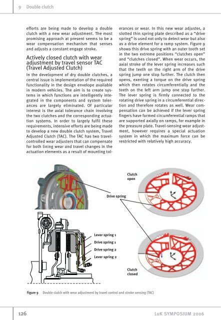
9 Double clutch efforts are being made to develop a double clutch with a new wear adjustment. The most promising approach at present seems to be a wear compensation mechanism that senses and adjusts a constant engage stroke. Actively closed clutch with wear adjustment by travel sensor TAC (Travel Adjusted Clutch) In the development of dry double clutches, a central issue is implementation of the required functionality in the design envelope available in modern vehicles. The aim is to create systems in which functions are intelligently integrated in the components and system tolerances are largely eliminated. Of particular interest is the axial tolerance chain involving the two clutches and the corresponding actuation systems. In order to largely fulfil these requirements, intensive efforts are being made to develop a new double clutch system, Travel Adjusted Clutch (TAC). The TAC has two travelcontrolled wear adjusters that can compensate for both lining wear and travel changes in the actuation elements as a result of mounting tol- Figure 9 Double clutch with wear adjustment by travel control and stroke sensing (TAC) erances or wear. In this new wear adjuster, a slotted thin spring plate described as a “drive spring” is used not only to detect wear but also as a drive element for a ramp system. Figure 9 shows this drive spring with an outer tooth set in the two extreme positions “clutches open” and “clutches closed”. When wear occurs, the axial stroke of the lever spring increases such that the teeth on the right arm of the drive spring jump one stop further. The clutch then opens, exerting a torque on the drive spring which then rotates circumferentially and the teeth on the left arm jump one stop further. The lever spring is firmly connected to the rotating drive spring in a circumferential direction and therefore rotates as well. Wear compensation can be achieved if the lever spring fingers have formed circumferential ramps that are supported axially on ramps, for example in the preasure plate. Travel-sensing wear adjustment, however requires a special actuation system in which the maximum force can be restricted with relatively high accuracy. 126 LuK SYMPOSIUM 2006
The wet clutch Complexity and requirements The wet double clutches currently in the market or due to enter the market in the near future are actuated by hydraulic means. The pressure chambers rotate at the speed of the internal combustion engine (figure 10). This design with rotating actuator pistons is generally also used for the clutches in classical converter transmissions. In order to move the hydraulic oil from the hydraulic unit to the pressure chambers, rotary passages are required that are sealed by slotted dynamic seals allowing leakage. This leakage is one reason why an additional hydraulic power pack is necessary to hold the clutch at the contact point while the engine is not rotating in order to achieve stop/start functionality. The clutch can then be closed easily and quickly when the engine restarts. The pressure chambers are sealed by two seals each on the inside and outside diameter. In order to compensate for the influence of the centrifugal oil pressure that builds up under rota- Figure 10 Wet double clutch with rotating actuator pistons LuK SYMPOSIUM 2006 Figure 11 Wet lever-actuated double clutch Double clutch 9 tion, additional oil chambers are included parallel to pressure chambers. At least one further seal is required per centrifugal oil chamber. The seals are largely responsible for the hysteresis in clutch actuation. LuK, however, favours an actuation concept using lever springs similar to the state of the art used in dry, actively closed clutches (figure 11). The force is applied by the non-rotating, static actuation elements via engage bearings to the lever springs rotating at engine speed [5]. The engage bearings are thus the interface between stationary and rotating parts. The lever spring is suspended in the outer disc carrier and actuates a contact ring that presses the disc assembly together. If an actuator fails, the clutch opens automatically because of the force of lever spring. The external actuation forces are supported directly on a cover bearing, so the crankshaft is free from axial forces. This system has the advantage that several actuation systems are suitable for use. If hydrostatic actuation elements or rotary or swivel levers are used in combination with slave cylinders, classic hydraulic control systems and electrohydraulic power packs can be utilised. An electromechanical actuator system can be simply adapted, too. Actuation systems with an electrically-driven energy source independent of the internal com- 127
- Page 1 and 2: LuK SYMPOSIUM 2006 Double clutch -
- Page 3 and 4: Figure 2 Comparison of passively cl
- Page 5 and 6: Figure 4 Clutch temperature curve a
- Page 7: Figure 7 Double clutch with small i
- Page 11 and 12: Figure 13 Comparison of lever actua
- Page 13 and 14: Figure 16 New cooling concept The h
- Page 15 and 16: higher fuel consumption; the actuat
- Page 17: Figure 20 Modular clutch concept Lu
9 <strong>Double</strong> <strong>clutch</strong><br />
efforts are being made to develop a double<br />
<strong>clutch</strong> with a new wear adjustment. The most<br />
promising approach at present seems to be a<br />
wear compensation mechanism that senses<br />
and adjusts a constant engage stroke.<br />
Actively closed <strong>clutch</strong> with wear<br />
adjustment by travel sensor TAC<br />
(Travel Adjusted Clutch)<br />
In the development of dry double <strong>clutch</strong>es, a<br />
central issue is implementation of the required<br />
functionality in the design envelope available<br />
in modern vehicles. The aim is to create systems<br />
in which functions are intelligently integrated<br />
in the components and system tolerances<br />
are largely eliminated. Of particular<br />
interest is the axial tolerance chain involving<br />
the two <strong>clutch</strong>es and the corresponding actuation<br />
systems. In order to largely fulfil these<br />
requirements, intensive efforts are being made<br />
to develop a new double <strong>clutch</strong> system, Travel<br />
Adjusted Clutch (TAC). The TAC has two travelcontrolled<br />
wear adjusters that can compensate<br />
for both lining wear and travel changes in the<br />
actuation elements as a result of mounting tol-<br />
Figure 9 <strong>Double</strong> <strong>clutch</strong> with wear adjustment by travel control and stroke sensing (TAC)<br />
erances or wear. In this new wear adjuster, a<br />
slotted thin spring plate described as a “drive<br />
spring” is used not only to detect wear but also<br />
as a drive element for a ramp system. Figure 9<br />
shows this drive spring with an outer tooth set<br />
in the two extreme positions “<strong>clutch</strong>es open”<br />
and “<strong>clutch</strong>es closed”. When wear occurs, the<br />
axial stroke of the lever spring increases such<br />
that the teeth on the right arm of the drive<br />
spring jump one stop further. The <strong>clutch</strong> then<br />
opens, exerting a torque on the drive spring<br />
which then rotates circumferentially and the<br />
teeth on the left arm jump one stop further.<br />
The lever spring is firmly connected to the<br />
rotating drive spring in a circumferential direction<br />
and therefore rotates as well. Wear compensation<br />
can be achieved if the lever spring<br />
fingers have formed circumferential ramps that<br />
are supported axially on ramps, for example in<br />
the preasure plate. Travel-sensing wear adjustment,<br />
however requires a special actuation<br />
system in which the maximum force can be<br />
restricted with relatively high accuracy.<br />
126 LuK SYMPOSIUM 2006


