
You also want an ePaper? Increase the reach of your titles
YUMPU automatically turns print PDFs into web optimized ePapers that Google loves.
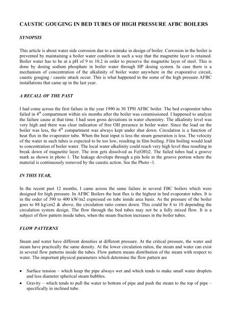
CAUSTIC GOUGING IN BED TUBES OF HIGH PRESSURE <strong>AFBC</strong> BOILERS<br />
SYNOPSIS<br />
This article is about water side corrosion due to a mistake <strong>in</strong> design <strong>of</strong> boiler. Corrosion <strong>in</strong> the boiler is<br />
prevented by ma<strong>in</strong>ta<strong>in</strong><strong>in</strong>g a boiler water condition <strong>in</strong> such a way that the magnetite layer is reta<strong>in</strong>ed.<br />
Boiler water has to be at a pH <strong>of</strong> 9 to 10.2 <strong>in</strong> order to preserve the magnetite layer <strong>of</strong> steel. This is<br />
done by dos<strong>in</strong>g sodium phosphate <strong>in</strong> boiler water through HP dos<strong>in</strong>g system. In case there is a<br />
mechanism <strong>of</strong> concentration <strong>of</strong> the alkal<strong>in</strong>ity <strong>of</strong> boiler water anywhere <strong>in</strong> the evaporative circuit,<br />
caustic <strong>goug<strong>in</strong>g</strong> / caustic attack occur. This is what happened <strong>in</strong> the some <strong>of</strong> the <strong>high</strong> <strong>pressure</strong> <strong>AFBC</strong><br />
<strong>in</strong>stallations that came up <strong>in</strong> the last year.<br />
A RECALL OF THE PAST<br />
I had come across the first failure <strong>in</strong> the year 1990 <strong>in</strong> 30 TPH <strong>AFBC</strong> boiler. The <strong>bed</strong> evaporator <strong>tubes</strong><br />
failed <strong>in</strong> 4 th compartment with<strong>in</strong> six months after the boiler was commissioned. I happened to analyze<br />
the failure cause at that time. I had seen gross deviations <strong>in</strong> water chemistry. The alkal<strong>in</strong>ity level was<br />
very <strong>high</strong> and there was clear <strong>in</strong>dication <strong>of</strong> free OH presence <strong>in</strong> boiler water. S<strong>in</strong>ce the load on the<br />
boiler was less, the 4 th compartment was always kept under shut down. Circulation is a function <strong>of</strong><br />
heat flux <strong>in</strong> the evaporator tube. When the heat <strong>in</strong>put is less the steam generation is less. The velocity<br />
<strong>of</strong> the water <strong>in</strong> such <strong>tubes</strong> is expected to be too low, result<strong>in</strong>g <strong>in</strong> film boil<strong>in</strong>g. Film boil<strong>in</strong>g would lead<br />
to concentration <strong>of</strong> boiler water. The local water alkal<strong>in</strong>ity could reach very <strong>high</strong> level thus result<strong>in</strong>g <strong>in</strong><br />
break down <strong>of</strong> magnetite layer. The iron gets dissolved as Fe(OH)2. The failed <strong>tubes</strong> had a groove<br />
mark as shown <strong>in</strong> photo 1. The leakage develops through a p<strong>in</strong> hole <strong>in</strong> the groove portion where the<br />
material is cont<strong>in</strong>uously removed by the caustic action. See the Photo -1.<br />
IN THIS YEAR,<br />
In the recent past 12 months, I came across the same failure <strong>in</strong> several FBC <strong>boilers</strong> which were<br />
designed for <strong>high</strong> <strong>pressure</strong>. In <strong>AFBC</strong> Boilers the heat flux is the <strong>high</strong>est <strong>in</strong> <strong>bed</strong> evaporator <strong>tubes</strong>. It is<br />
<strong>in</strong> the order <strong>of</strong> 390 to 400 kW/m2 expressed on tube <strong>in</strong>side area basis. As the <strong>pressure</strong> <strong>of</strong> the boiler<br />
goes to 88 kg/cm2 & above, the circulation ratio comes down. This could be 8 to 10 depend<strong>in</strong>g the<br />
circulation system design. The flow through the <strong>bed</strong> <strong>tubes</strong> may not be a fully mixed flow. It is a<br />
subject <strong>of</strong> flow pattern <strong>in</strong>side <strong>tubes</strong>, when the steam fraction <strong>in</strong>creases <strong>in</strong> the boiler <strong>tubes</strong>.<br />
FLOW PATTERNS<br />
Steam and water have different densities at different <strong>pressure</strong>. At the critical <strong>pressure</strong>, the water and<br />
steam have practically the same density. At the lower circulation ratios, the steam and water can exist<br />
<strong>in</strong> several flow patterns <strong>in</strong>side the <strong>tubes</strong>. Flow pattern means distribution <strong>of</strong> the steam with respect to<br />
water. The important physical parameters which determ<strong>in</strong>e the flow pattern are<br />
• Surface tension – which keep the pipe always wet and which tends to make small water droplets<br />
and less diameter spherical steam bubbles.<br />
• Gravity – which tends to pull the water to bottom <strong>of</strong> pipe and push the steam to the top <strong>of</strong> pipe –<br />
specifically <strong>in</strong> <strong>in</strong>cl<strong>in</strong>ed tube.
There are various patterns <strong>of</strong> flow that exist <strong>in</strong>side <strong>tubes</strong>. The patterns are def<strong>in</strong>ed with respect to<br />
orientation <strong>of</strong> <strong>tubes</strong>.<br />
FLOW PATTERN IN VERTICALLY ORIENTED TUBE<br />
The common flow patterns for vertical upward flow, which is when the boiler tube is oriented vertical,<br />
are as shown <strong>in</strong> figure 1. As the quality, that is steam to water ratio <strong>in</strong>creases, the flow patterns change<br />
from bubbly to wispy annular flow. In the boiler the steam / water ratio that is prevail<strong>in</strong>g <strong>in</strong> the<br />
particular circuit along with the mass flux would have decided the flow pattern <strong>in</strong>side tube.<br />
Undoubtedly, the flow has to be bubbly flow so that the water / steam flow well mixed <strong>in</strong>side tube<br />
without any steam blanket<strong>in</strong>g <strong>in</strong>side the tube. Otherwise the metal temperature would go up result<strong>in</strong>g<br />
<strong>in</strong> tube bursts.<br />
Bubbly flow: the steam / water bubbles are uniform <strong>in</strong> size.<br />
Slug / Plug flow: the steam flows as large bullet shaped bubble. Also the steam bubbles prevail as<br />
small bubbles <strong>in</strong> water. This flow pattern is also called plug flow.<br />
Churn flow: Highly unstable flow <strong>of</strong> oscillatory <strong>in</strong> nature. The water near the tube walls cont<strong>in</strong>uously<br />
pulses up and down.<br />
Annular flow: The liquid travels partly as annular film on the walls <strong>of</strong> the tube and partly as small<br />
drops distributed <strong>in</strong> the steam which flows <strong>in</strong> the centre <strong>of</strong> the <strong>tubes</strong>.<br />
Wispy- annular flow: As the water flow rate is <strong>in</strong>creased <strong>in</strong> annular flow, the concentration <strong>of</strong> drops <strong>in</strong><br />
the steam core <strong>in</strong>creases. Ultimately the droplet concentration <strong>in</strong> the core leads to large lumps or<br />
streaks / wisps <strong>of</strong> water <strong>in</strong> the steam core. The flow pattern is the characteristic <strong>of</strong> <strong>high</strong> mass flux.<br />
FLOW PATTERN IN HORIZONTALLY ORIENTED TUBE<br />
The phases tend to separate due to density difference caus<strong>in</strong>g a form <strong>of</strong> stratified flow to be very<br />
common. This makes the heavier water phase to accumulate at the bottom <strong>of</strong> tube. When the tube is<br />
<strong>in</strong>cl<strong>in</strong>ed at an angle the pattern the slug / plug flow is common. The common flow patterns <strong>in</strong><br />
horizontal <strong>tubes</strong> are illustrated <strong>in</strong> figure 2.<br />
Flow patterns vary from that <strong>of</strong> vertical <strong>tubes</strong> due to gravitational forces which act perpendicular to the<br />
direction <strong>of</strong> flow. As the steam fraction <strong>in</strong>creases, the flow pattern changes from Plug to annular flow.<br />
Plug flow: The <strong>in</strong>dividual steam bubbles have coalesced to produce long plugs. The steam bubbles<br />
tend to flow along the top <strong>of</strong> the tube.<br />
Stratified flow: the steam to water <strong>in</strong>terface is smooth.<br />
Wavy flow: the stratified flow may not rema<strong>in</strong> smooth for long as the steam fraction <strong>in</strong>creases, the<br />
flow becomes wavy.<br />
Slug flow: the wave amplitude is so large that the wave touches the top <strong>of</strong> the tube.<br />
Dispersed bubble flow: many small steam bubbles are distributed uniformly across the entire tube<br />
cross section when the steam and water velocities are <strong>high</strong>.<br />
Figure 3 is the very well known representation <strong>of</strong> the steam bubble behavior <strong>in</strong>side a horizontally<br />
oriented tube. It is the designer’s job to design the evaporation circuit with proper downcomer and<br />
riser arrangements, evaporator tube arrangements to ensure the nucleate boil<strong>in</strong>g prevails <strong>in</strong> each part<br />
<strong>of</strong> the boil<strong>in</strong>g circuit.<br />
WHAT CAN HAPPEN INSIDE THE BED TUBE UNDER VERY LESS HEAT INPUT?<br />
When the velocity <strong>in</strong>side the tube is less, the steam bubble may rise to the top and form a bubble<br />
adher<strong>in</strong>g to tube wall at 12 o clock position. In vertically oriented tube the steam bubble would get <strong>in</strong> to
the water phase. As the steam bubble sticks to the top, the water beg<strong>in</strong>s to concentrate <strong>in</strong> alkal<strong>in</strong>ity.<br />
The <strong>tubes</strong> may not fail due to steam blanket<strong>in</strong>g because the gas side temperature may be low. But<br />
corrosion mechanism beg<strong>in</strong>s and results <strong>in</strong> a gouged tube as seen <strong>in</strong> photo 2.<br />
WHAT CAN HAPPEN INSIDE BED TUBE UNDER SITUATION OF HIGH HEAT INPUT,<br />
HORIZONTAL / LOW SLOPED ORIENTATION / LESS VELOCITY?<br />
High heat <strong>in</strong>put would help <strong>in</strong> form<strong>in</strong>g more steam bubbles to facilitate the growth <strong>of</strong> the bubble. As<br />
the bubble size <strong>in</strong>creases, it would raise to the top <strong>of</strong> the tube <strong>in</strong> the absence <strong>of</strong> sufficient horizontal<br />
velocity or when the tube is horizontal or <strong>in</strong>cl<strong>in</strong>ed to very low angle. Now the steam forms a blanket<br />
<strong>in</strong>side the tube, may be for a moment, before be<strong>in</strong>g washed away by water.<br />
SO WHAT IF THE STEAM BLANKETS THE TUBE?<br />
When the blanket is heavy and <strong>in</strong> the absence <strong>of</strong> horizontal velocity component, the steam would get<br />
superheated and tube would have failed due to <strong>high</strong> metal temperature. The failure would have been<br />
<strong>in</strong>stantaneous. This is called dry out and the heat flux is called critical heat flux.<br />
When there is a horizontal velocity component the steam bubbles and water wett<strong>in</strong>g alternately take<br />
place at the top <strong>of</strong> the tube. This is descri<strong>bed</strong> as slug flow / <strong>in</strong>termittent flow. Now we have a<br />
mechanism <strong>of</strong> local concentration <strong>of</strong> solids due to evaporative boil<strong>in</strong>g. The water go<strong>in</strong>g along the top<br />
<strong>of</strong> the <strong>tubes</strong> has a different velocity as compared to the stream <strong>of</strong> water go<strong>in</strong>g along bottom <strong>of</strong> <strong>tubes</strong>.<br />
This boiler water sample, upon which the control is based, represents an average <strong>of</strong> all the water<br />
with<strong>in</strong> the boiler and as such it conta<strong>in</strong>s water subjected to both the most severe and the least severe<br />
conditions with<strong>in</strong> the boiler. Hence water chemistry except for presence <strong>of</strong> corroded iron at drum<br />
<strong>in</strong>ternals, does not <strong>in</strong>dicate concentration <strong>of</strong> solids / chemicals <strong>in</strong>side the low sloped <strong>bed</strong> <strong>tubes</strong>. The<br />
low slope <strong>tubes</strong> may prevent adequate mix<strong>in</strong>g with the bulk liquid phase and over time, a<br />
concentration gradient will develop between the bulk boiler water and the localized solution <strong>in</strong> contact<br />
with the magnetite surface. Localized concentrations for some species may be two or more orders <strong>of</strong><br />
magnitude <strong>high</strong>er than <strong>in</strong> the bulk boiler water (Cohen et al., 1962). Under these conditions, species,<br />
such as NaOH and NaCl, with relatively <strong>high</strong> solubilities tend to stay <strong>in</strong> solution, while those <strong>of</strong> more<br />
limited solubility, such as those <strong>in</strong>corporat<strong>in</strong>g phosphate species, may exceed their solubility limits,<br />
and undergo precipitation. In general wherever the <strong>tubes</strong> had failed due to <strong>goug<strong>in</strong>g</strong>, the analysis<br />
<strong>in</strong>dicated phosphate salts.<br />
APPEARANCES OF FAILED BED TUBES<br />
The <strong>goug<strong>in</strong>g</strong> type failures (as <strong>in</strong> photo 1) have been seen <strong>in</strong> at least six <strong>in</strong>stallations where the slope <strong>of</strong><br />
the <strong>bed</strong> tube happened to be less than 5 deg. The steam to water fraction happened to be <strong>high</strong>er and the<br />
overall circulation ratio was estimated as 8-12. Depend<strong>in</strong>g upon the water outlet temperature at<br />
economiser, the water <strong>in</strong>side the <strong>bed</strong> <strong>tubes</strong> beg<strong>in</strong> to boil at a distance from the wall. The <strong>goug<strong>in</strong>g</strong> mark<br />
was seen <strong>in</strong>side the tube after the steam<strong>in</strong>g po<strong>in</strong>t. At one unit where the economiser outlet water<br />
temperature was very less, the <strong>goug<strong>in</strong>g</strong> was seen <strong>in</strong> the upper portion <strong>of</strong> hairp<strong>in</strong> <strong>bed</strong> coil.<br />
WHAT NEEDS TO BE DONE TO DELAY THE FAILURE?<br />
When it happened, the immediate concern was to how to keep the boiler on l<strong>in</strong>e before any remedial<br />
measures could be taken.<br />
1. Operat<strong>in</strong>g at lower loads / lower <strong>pressure</strong> will lead to delayed failure. This is ma<strong>in</strong>ly due to the<br />
reason that the steam to water ratio is more at rated load & rated <strong>pressure</strong>.
2. Operation <strong>of</strong> the boiler with<strong>in</strong> narrow range <strong>of</strong> phosphate <strong>of</strong>fers a time delay aga<strong>in</strong>st unavoidable<br />
failure.<br />
WHAT IS TO BE DONE TO PREVENT THE FAILURES IN FUTURE?<br />
When it was zeroed down that the angle <strong>of</strong> slope <strong>of</strong> the <strong>bed</strong> coil was the prime cause for failure, the<br />
next question was how to rectify the design defect.<br />
1. To prevent failure the slope <strong>of</strong> the tube has to be raised. In many cases the <strong>in</strong>crease <strong>in</strong> angle would<br />
have resulted <strong>in</strong> less <strong>bed</strong> HTA. Alternate configurations have to be thought <strong>of</strong> to avoid lower<br />
slopes. While replacement <strong>of</strong> <strong>bed</strong> <strong>tubes</strong> <strong>in</strong>creased slopes shall be considered. This conclusion was<br />
based on one boiler operat<strong>in</strong>g with 10 deg slope at 110 kg/cm2 <strong>pressure</strong>.<br />
2. The circulation ratio can be improved by adopt<strong>in</strong>g better designed downcomer riser layout. We can<br />
not adopt a common downcomer system for two circuits which have different heat flux. This<br />
mistake is seen <strong>in</strong> some units: the downcomer is common for water walls that were hav<strong>in</strong>g less<br />
steam<strong>in</strong>g rates. In such circuits there will be poor flow rates. This also reduces the mass flow rate<br />
<strong>in</strong> <strong>bed</strong> <strong>tubes</strong> depend<strong>in</strong>g upon how the branch<strong>in</strong>g is done.<br />
3. Rifle bore / <strong>in</strong>ternally rib<strong>bed</strong> <strong>tubes</strong> are to be used to enhance mix<strong>in</strong>g <strong>of</strong> steam and water. In the<br />
<strong>in</strong>stallations where the <strong>tubes</strong> had already failed this was the only solution. Rifle bore <strong>tubes</strong> have<br />
spiral ribs which impart swirl<strong>in</strong>g motion to steam-water mixture flow<strong>in</strong>g through the <strong>tubes</strong>. The<br />
mix<strong>in</strong>g <strong>of</strong> steam & water ensures the constituents <strong>of</strong> water <strong>in</strong>side the tube are the same as that <strong>of</strong><br />
bulk water. Rifle bore / <strong>in</strong>ternally rib<strong>bed</strong> <strong>tubes</strong> are be<strong>in</strong>g used <strong>in</strong> once-through <strong>boilers</strong>. In future for<br />
88 kg/cm2 and beyond, rifle bore <strong>tubes</strong> are to be used.<br />
A REVIEW OF CAUSTIC GOUGING MECHANISMS<br />
<strong>Caustic</strong> <strong>goug<strong>in</strong>g</strong> is a form <strong>of</strong> corrosion <strong>of</strong> steel. It generally results from fouled heat<strong>in</strong>g surface and the<br />
active corrodent (sodium hydroxide) <strong>in</strong> the boiler water. Concentrated solutions <strong>of</strong> alkali occur <strong>in</strong><br />
situations where the normal water wash<strong>in</strong>g <strong>of</strong> tube metal is restricted after the steam bubble release.<br />
The concentrations <strong>of</strong> corrosive solutions occur at the heat transfer surfaces as the result <strong>of</strong> foul<strong>in</strong>g by<br />
porous deposits such as iron and copper oxides. These deposits are typically formed from particles<br />
suspended <strong>in</strong> boiler water. Once the corrosive concentration mechanism is started, the additional<br />
corrosion products are generated from porous deposits. Boil<strong>in</strong>g under the deposits is <strong>of</strong>ten referred as<br />
Wick boil<strong>in</strong>g. Boiler water permeates the porous deposit by capillary action through small pores like a<br />
liquid permeat<strong>in</strong>g a wick. Steam then escapes through the larger pores (channels) leav<strong>in</strong>g non volatile<br />
solutes beh<strong>in</strong>d. These new deposits then concentrate beneath deposits.<br />
Feedwater solids concentrate <strong>in</strong> the boiler relative to blow down rates. Boiler water solids may<br />
concentrate an additional 2000 times at the heat transfer surface as a result <strong>of</strong> a concentrat<strong>in</strong>g film<br />
produced from non boil<strong>in</strong>g equilibrium. The formation <strong>of</strong> a steam bubble further concentrates boiler<br />
solids. These conditions are most likely reached <strong>in</strong> the presence <strong>of</strong> porous deposit.<br />
Once the local caustic concentrations are reached such that caustic attack occurs, the corrosion can<br />
proceed to failure <strong>in</strong> a very short time. <strong>Caustic</strong> corrosion is an irregular th<strong>in</strong>n<strong>in</strong>g or <strong>goug<strong>in</strong>g</strong> <strong>of</strong> the tube<br />
water side surface. Areas subject to caustic attack typically show smooth round roll<strong>in</strong>g contours<br />
surrounded by encrusted boiler water solids and crystall<strong>in</strong>e dense oxides. The oxides however are not<br />
protective. Particles <strong>of</strong> metallic copper may also be em<strong>bed</strong>ded <strong>in</strong> the deposit layer.<br />
Failures due to caustic attack are caused by metal loss. The damage progresses to failure when the tube<br />
wall th<strong>in</strong>s to a po<strong>in</strong>t where rupture occurs locally. The microstructure does not change and the tube<br />
metal reta<strong>in</strong>s ductility.<br />
<strong>Caustic</strong> attack can also lead to other type <strong>of</strong> failures. One form is the hydrogen damage which results<br />
from hydrogen liberated <strong>in</strong> the corrosion process diffus<strong>in</strong>g <strong>in</strong> to the metal. The hydrogen can then
eact with iron carbides <strong>in</strong> the metal to produce methane which develops <strong>pressure</strong> lead<strong>in</strong>g to the<br />
formation <strong>of</strong> <strong>in</strong>ter-crystall<strong>in</strong>e cracks. Stress corrosion crack<strong>in</strong>g can also occur due to hydrogen<br />
diffusion along the gra<strong>in</strong> boundaries.<br />
DETAILED CORROSION MECHANISM<br />
FORMATION OF MAGNETITE LAYER<br />
The control <strong>of</strong> corrosion <strong>in</strong> boiler environment is<br />
based on ma<strong>in</strong>ta<strong>in</strong><strong>in</strong>g conditions which enhance<br />
passive film formation. Magnetite, Fe 3 O 4 is the<br />
preferred <strong>high</strong> temperature iron oxide form. Well<br />
crystallized (unhydrated) magnetite forms a dense<br />
layer result<strong>in</strong>g <strong>in</strong> excellent passivation. The<br />
formation <strong>of</strong> magnetite takes place as shown below.<br />
Fe 2+<br />
Fe 3+<br />
Ferrous ion<br />
Ferric Ion<br />
FeO Ferrous oxide – Iron II oxide<br />
Fe 2 O 3 Ferric oxide – Iron III oxide<br />
Fe 3 O 4 Ferrous ferric oxide – Iron II, III oxide<br />
FeOH 2 Iron II hydroxide<br />
FeO(OH) Iron II oxide hydroxide<br />
Fe(OH) 3 Iron III hydroxide<br />
(Reaction -1) Fe + 2H 2 O Fe +2 + 2OH - + H 2<br />
(Reaction -2) Fe +2 + 2OH - Fe (OH) 2<br />
(Reaction -3) 3Fe(OH) 2 Fe 3 O 4 + 2H 2 O + H 2<br />
It is seen from reaction 2, that the hydroxyl ions are to help <strong>in</strong> cont<strong>in</strong>uous formation <strong>of</strong> Fe(OH) 2 – that<br />
is soluble iron II oxide. Fe 3 O 4 forms over the <strong>in</strong>ner surface <strong>of</strong> tube <strong>of</strong>fer<strong>in</strong>g a cont<strong>in</strong>uous protection.<br />
On the whole it is a passivation process is basically due to an active surface <strong>of</strong> Fe be<strong>in</strong>g corroded to a<br />
relatively <strong>in</strong>active state <strong>of</strong> Fe 3 O 4 .<br />
Under good operat<strong>in</strong>g condition, the oxidation <strong>of</strong> iron to magnetite at the metal surface is slow<br />
because the magnetite forms a f<strong>in</strong>e, tight adherent layer with good protective properties. The film<br />
generally displays good adhesive strength <strong>in</strong> part because thermal coefficients <strong>of</strong> l<strong>in</strong>er expansion for<br />
magnetite and layer are very similar. Therefore vary<strong>in</strong>g heat load and surface temperature do not cause<br />
undue stress between the film and the underly<strong>in</strong>g metal surface.<br />
DETERIORATION OF MAGNETITE LAYER IN HIGHLY ALKALINE ENVIRONMENT<br />
Magnetite is considered to be a co polymer <strong>of</strong> the iron (II) hydroxide –FeO and iron (III) oxide –<br />
Fe2O3. In this system the bonds <strong>of</strong> divalent iron are more easily hydrolyzed. That is FeO can become<br />
FeO.OH by the follow<strong>in</strong>g equation. The iron (II) hydroxide system (aqueous) is considered to be <strong>in</strong><br />
solution equilibrium with magnetite as follows.<br />
(Reaction -4) - Fe 3 O 4 + 2H 2 O Fe(OH) 2 + 2FeO.OH<br />
The solubility <strong>of</strong> magnetite layer <strong>in</strong> <strong>high</strong>ly alkal<strong>in</strong>e atmosphere (OH - ) is expla<strong>in</strong>ed as below. Under<br />
<strong>high</strong>ly alkal<strong>in</strong>e conditions the ferrous hydroxide <strong>in</strong> solution may react as follows.<br />
(Reaction -5) - Fe(OH) 2 + OH- Fe(OH) 3 HFeO 2 + 2H 2 O<br />
(Reaction -6) - Fe(OH) 2 + 2OH- Fe(OH) 4 FeO 2 -2 + 2H 2 O
<strong>Caustic</strong> attack occurs <strong>in</strong> this manner through activation <strong>of</strong> the carbon steel surface by removal <strong>of</strong><br />
passive oxide layer <strong>in</strong>hibit<strong>in</strong>g its formation. These conditions lead to the formation <strong>of</strong> a velvet black,<br />
f<strong>in</strong>ely crystall<strong>in</strong>e, reactive magnetite. It has low adherence and practically no protective effect.<br />
As a result the magnetite layer is dissolved <strong>in</strong> the form soluble ferrate ions as the equilibrium <strong>in</strong><br />
reaction 4 is driven to the right via removal <strong>of</strong> ferrous oxide. In addition further formation <strong>of</strong><br />
magnetite layer is <strong>in</strong>hibited as the equilibrium <strong>in</strong> reaction 2 is driven to favor soluble ferrate ion<br />
formation <strong>in</strong>stead <strong>of</strong> magnetite as illustrated <strong>in</strong> reaction 3.<br />
The distortion <strong>of</strong> equilibrium illustrated <strong>in</strong> reactions 2 and 4 follow<strong>in</strong>g the reactions 5 and 6 requires<br />
the presence <strong>of</strong> very <strong>high</strong> concentration <strong>of</strong> hydroxyl ions. Concentration <strong>of</strong> hydroxyl ions can be found<br />
at boiler heat<strong>in</strong>g surfaces where normal wash<strong>in</strong>g <strong>of</strong> surfaces by boiler water is restricted due to either<br />
presence <strong>of</strong> deposits or the development <strong>of</strong> a film <strong>of</strong> superheated steam at the surface <strong>of</strong> tube.<br />
CONCLUSION<br />
To summarize, steam blanket<strong>in</strong>g can also lead to caustic <strong>goug<strong>in</strong>g</strong>. This occurs when stratification <strong>of</strong><br />
the steam water mixture produces <strong>high</strong> concentration <strong>of</strong> caustic. Steam blanket<strong>in</strong>g can occur when the<br />
fluid velocity is <strong>in</strong>sufficient to ma<strong>in</strong>ta<strong>in</strong> turbulence and produce phase mix<strong>in</strong>g. Steam blanket<strong>in</strong>g can<br />
also occur <strong>in</strong> low sloped <strong>tubes</strong> where the heat flux is <strong>high</strong>.
Figure 1: flow patterns <strong>in</strong> vertical oriented tube.<br />
Figure 2. Flow patterns <strong>in</strong> horizontal <strong>tubes</strong>.<br />
Figure 3. Boil<strong>in</strong>g phenomenon <strong>in</strong> horizontal <strong>tubes</strong> for various steam fraction.
Photo 1- shows the deposition <strong>of</strong> chemical at<br />
top portion <strong>of</strong> <strong>bed</strong> tube.<br />
Photo 2- shows the material loss at<br />
top portion <strong>of</strong> <strong>bed</strong> tube.<br />
Photo 3- shows the <strong>in</strong>ternally rib<strong>bed</strong><br />
tube / also known as rifle bore tube.