
Create successful ePaper yourself
Turn your PDF publications into a flip-book with our unique Google optimized e-Paper software.
CASE STUDIES IN FAILURES IN BOILERS<br />
By K.K.Parthiban, Sri Devi Boiler Equipment and Spares- Karnataka & Venus energy audit system – Tamilnadu<br />
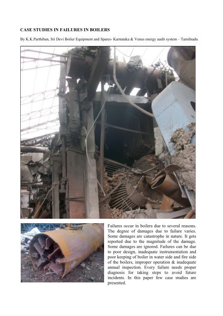
Failures occur <strong>in</strong> <strong>boiler</strong>s due to several reasons.<br />
The degree of damages due to failure varies.<br />
Some damages are catastrophe <strong>in</strong> nature. It gets<br />
reported due to the magnitude of the damage.<br />
Some damages are ignored. Failures can be due<br />
to poor design, <strong>in</strong>adequate <strong>in</strong>strumentation and<br />
poor keep<strong>in</strong>g of <strong>boiler</strong> <strong>in</strong> water side and fire side<br />
of the <strong>boiler</strong>s, improper operation & <strong>in</strong>adequate<br />
annual <strong>in</strong>spection. Every failure needs proper<br />
diagnosis for tak<strong>in</strong>g steps to avoid future<br />
<strong>in</strong>cidents. In this paper few case <strong>studies</strong> are<br />
presented.
CASE STUDY 1- FAILURE ANALYSIS OF FURNACE SHELL PLATE<br />
The <strong>boiler</strong> is an 8 TPH oil fired <strong>boiler</strong>. It is a three pass wet back <strong>boiler</strong>. The furnace shell plate had<br />
failed <strong>in</strong> a repetitive manner. The furnace shell plate had bulged <strong>in</strong>side two times <strong>in</strong> a six month<br />
period. The location was seen to be about 1.5 meter from the front tube sheet. The orientation of<br />
failed portion was at 6 o clock position. The plate had caved towards the furnace due to <strong>in</strong>ternal steam<br />
pressure. The plate was locally replaced dur<strong>in</strong>g the first failure. The second failure was also <strong>in</strong> the<br />
same location. After the bulg<strong>in</strong>g had taken place, the water started seep<strong>in</strong>g from the repair weldment<br />
itself. After observ<strong>in</strong>g black smoke <strong>in</strong> chimney, the <strong>boiler</strong> was stopped by the <strong>boiler</strong> operators.<br />
Observations dur<strong>in</strong>g the visit<br />
1. The failed portions of the plates were seen to be bulg<strong>in</strong>g towards the axis of the furnace. Scale<br />
was seen underneath the plates on water side. The extent of scales for the first failure was not<br />
known. However this time the scal<strong>in</strong>g was found to be about 0.5 mm.<br />
2. Apart from this, the <strong>boiler</strong> showed a small layer of hardness scale over the tubes. The scale is<br />
seen to be very high where the water is fed <strong>in</strong> to the <strong>boiler</strong>. There is def<strong>in</strong>itely slipp<strong>in</strong>g of<br />
hardness to <strong>boiler</strong>.<br />
3. The <strong>boiler</strong> water TDS reports confirmed that the TDS had been as high as 10000 ppm before first<br />
failure. After the chemical clean<strong>in</strong>g, <strong>in</strong>structions were given to operators to <strong>in</strong>crease the blow<br />
down and ma<strong>in</strong>ta<strong>in</strong> 5000 ppm of TDS <strong>in</strong> <strong>boiler</strong> water. Even then, the water TDS was seen to<br />
<strong>in</strong>crease along with pH as reported by operators. In fact the pH booster dosage was stopped<br />
see<strong>in</strong>g the pH go<strong>in</strong>g to 11. This could have been happened due to high dosage rate of anti scalant.<br />
4. The chemical was be<strong>in</strong>g added through a small plastic tank with a cock for regulation. This could<br />
result <strong>in</strong> non-uniform dosage rates. The system would be dependent on skill of the persons.<br />
5. The burner was seen with a baffle plate <strong>in</strong>side the w<strong>in</strong>d box. It was suspected that there may not<br />
be uniform air flow <strong>in</strong> the burner. Hence a ribbon test was arranged to check the uniform<br />
distribution of air. It was found that there was m<strong>in</strong>imum air flow at the bottom portion. Ideally<br />
such a test must be conducted by an anemometer. The baffle plate was oriented vertically and the<br />
air distribution was checked for. An operator physically checked for distribution. This was much<br />
better this time. Yet quantification was required. A test with anemometer was recommended.<br />
Cause for shell plate <strong>failures</strong><br />
1. The plate had failed at the same place twice. This clearly po<strong>in</strong>ted out chances of flame<br />
imp<strong>in</strong>gement. Incidentally on flame imp<strong>in</strong>gement, the scale formation would be more. On<br />
<strong>in</strong>crease <strong>in</strong> metal temperature, the plate would swell and would lead to failure.<br />
2. There was scale present all over the <strong>boiler</strong>. It meant that there was deviation <strong>in</strong> water quality. Yet<br />
the scale thickness was not alarm<strong>in</strong>gly high. The <strong>boiler</strong> was cleaned off dislodged hardness scales<br />
<strong>in</strong>side the <strong>boiler</strong> shell. Yet the quantity of dislodged scales which were ly<strong>in</strong>g outside the <strong>boiler</strong><br />
house was seen to be meager.<br />
3. The feed water hardness was not monitored properly. Even when the hardness was reported to be<br />
24 & 44, Nalco representative had certified that all the water parameters were OK. His signed<br />
report was available.
Photo 1: The part of the furnace shell that bulged<br />
second time.<br />
Photo 2: The back side (water side) of the bulged<br />
plate, show<strong>in</strong>g scales (second time).<br />
Photo 3: Part of the furnace shell that bulged<br />
first.<br />
Photo 4: The back side (water side) of the bulged<br />
plate show<strong>in</strong>g the scales (first time).<br />
Photo 5: water side show<strong>in</strong>g small amount of<br />
scales.<br />
Photo 6: Burner air flow test. It showed less air<br />
flow at bottom when tested with flags.
Safety plan<br />
The follow<strong>in</strong>g were advised to the plant eng<strong>in</strong>eers:<br />
1. The furnace shell repair was not done to satisfactory level. Hence it was advised to carry out<br />
radiography test. But this could delay the <strong>boiler</strong> start<strong>in</strong>g as there were procedures <strong>in</strong> br<strong>in</strong>g<strong>in</strong>g the<br />
radioactive source. Hence it was arranged to have an ultrasonic test. The local company did that<br />
at site and certified that the weldment did not have cracks.<br />
2. The furnace shell was covered with 65 mm thick refractory brick layer to protect the weakened<br />
plate. Also this would prevent the flame imp<strong>in</strong>gement, if it was there earlier.<br />
3. Furnace shell is considered to be most vulnerable part of the <strong>boiler</strong>. For safety reasons,<br />
procedures should be followed. Manufacturer only should attend to such failure. Tube<br />
replacement is a different matter and it can be attended by a <strong>boiler</strong> repairer.<br />
4. Burner flame shape should be checked by the suppliers’ service technician at the earliest. There<br />
should not be any imp<strong>in</strong>gement.<br />
5. Water softener must be checked by the supplier. Hardness test kit should be replaced.<br />
6. Hardness levels should be checked before regeneration. This is an important aspect of the water<br />
chemistry.<br />
7. The water treatment chemical supplier is required to ensure that there is no deviation <strong>in</strong> water<br />
chemistry due to the wrong dosage of chemical itself.<br />
Boiler shell failure can result <strong>in</strong> catastrophe. Care is required to follow the proper procedure <strong>in</strong><br />
repair.
CASE STUDY 2: FAILURE INVESTIGATION OF A HIGH PRESSURE SHELL BOILER<br />
This is about an <strong>in</strong>vestigation of a Boiler accident <strong>in</strong> the 12 TPH, 35 kg/cm2, 350 deg C FBC <strong>boiler</strong><br />
at this plant.<br />
About this <strong>boiler</strong><br />
The <strong>boiler</strong> was <strong>in</strong>stalled about 4 years back. Almost two years the <strong>boiler</strong> had been <strong>in</strong> operation on a<br />
cont<strong>in</strong>uous basis after it was converted from grate fir<strong>in</strong>g to FBC. Previously the <strong>boiler</strong> was designed<br />
for wood chips. Later it was modified for rice husk cum GN shell fir<strong>in</strong>g. The <strong>boiler</strong> is provided with<br />
reciprocat<strong>in</strong>g pump. The feed l<strong>in</strong>e is connected to both shell & steam drum. The downcomers are<br />
taken from steam drum to waterwall, shell, bed coils by separate downcomers. The feed water is<br />
produced from a DM plant. The raw water TDS is < 300 ppm. The treated water TDS is about 0.1<br />
ppm only. The blow down TDS had been 50 ppm only. The shell tubes were also seen to be clear of<br />
any deposits.<br />
Incident<br />
The shell that comes after the convection SH is meant for steam generation as a <strong>boiler</strong> bank. This<br />
shell is made of two segments with a cirseam. The tube sheet and ma<strong>in</strong> shell are of 25 mm thick. The<br />
rear part of shell got ripped off from its place. Three persons lost their life <strong>in</strong> this <strong>in</strong>cident.<br />
Observations<br />
At the time of visit, the <strong>boiler</strong> parts were practically left <strong>in</strong> same condition after the <strong>in</strong>cident. The<br />
shell plate part that came off from the ma<strong>in</strong> shell was available for closer <strong>in</strong>spection. Also the ma<strong>in</strong><br />
shell could be exam<strong>in</strong>ed to some extent among the debris.<br />
Rul<strong>in</strong>g out water level loss<br />
It was learnt that the 2 nos Mobrey level controllers were operational. The feed pumps were always<br />
runn<strong>in</strong>g on / off based on switch action from Mobrey. In the event of low water level, the ma<strong>in</strong><br />
furnace tubes such waterwall & bed coils fail <strong>in</strong> this <strong>boiler</strong> s<strong>in</strong>ce they are <strong>in</strong> high temperature area. In<br />
the event that shell goes dry, the front tube sheet opens first and not the rear. Hence it was clear that<br />
the shell burst was not due to low water level.<br />
Possible failure modes- lamellar tear <strong>in</strong> raw material<br />
Generally such <strong>failures</strong> can happen due to raw material defect or manufactur<strong>in</strong>g defect. As the shell<br />
plate showed sign of lamellar tear<strong>in</strong>g, it could have been parent material defect. Usually the shell<br />
plates are 100% ultrasonically tested for overlapp<strong>in</strong>g and lamellar tears at sub surface level. It was<br />
advised to conduct an ultrasonic test alone the entire circumference of the failed plate. Yet the<br />
lamellar tear would not spread to entire circumference. It should have blown the shell by local<br />
open<strong>in</strong>g, as the tube sheet to shell weld was quite stronger. The <strong>boiler</strong> manufacturer who visited<br />
along with Inspect<strong>in</strong>g authority had blamed the <strong>in</strong>cident as raw material defect with lamellar crack <strong>in</strong><br />
the parent material itself.<br />
Possible failure modes- by cyclic stresses
The feed water stub is term<strong>in</strong>ated at shell at 450 mm from the rear tube sheet. There was no<br />
distributor pipe to direct the water away from shell plate & the weldment. The feed water<br />
temperature be<strong>in</strong>g 80 -90 deg C, there can be cyclic stresses at the shell to tube sheet jo<strong>in</strong>t.<br />
Fluctuat<strong>in</strong>g temperatures <strong>in</strong>troduce stresses which ultimately can lead to crack propagation.<br />
Possible failure modes- Improper weld<br />
On closer <strong>in</strong>spection at the rear tube sheet, it was seen that the <strong>in</strong>side seam weld is not properly<br />
fused. See photo below. Also the thick tube sheet at weld zone suggests that the tube sheet is not<br />
edge prepared properly before the weldment. If this is true, plate can shear along the thickness as it is<br />
a not properly fused jo<strong>in</strong>t. This would like a lamellar tear<strong>in</strong>g only. We can see one side of the weld<br />
hold<strong>in</strong>g the shell plate.<br />
Absence of sleeve design for feed pipe<br />
In high pressure <strong>boiler</strong>s, the feed pipe has to be welded to the ma<strong>in</strong> shell through a sleeve pipe. There<br />
has to be feed distributor pipe and water has to be admitted <strong>in</strong> water space and not near shell plate.<br />
The <strong>boiler</strong> had failed due to various design defects and poor workmanship only<br />
<br />
<br />
The edge preparation and weldment of shell & tubesheet was not as per code recommendations.<br />
The feedwater should not be pumped to shell where steam generation was there. The feed water<br />
should have been connected to steam drum only. This would have helped <strong>in</strong> better water<br />
chemistry at all circuits.<br />
Photo 1: It is seen that the tube sheet to shell weld is not torn off even a bit. This can happen if the<br />
fusion was not proper.
Tube sheet – This should be 3 mm at this edge<br />
Improperly fused<br />
Weldment<br />
Shell plate part<br />
Shell plate part<br />
Gas outlet duct plate<br />
Photo 2: This is the part of shell stick<strong>in</strong>g to the rear tube sheet. It is suggested to check the weld<br />
preparation once the <strong>boiler</strong> is brought down from the debris. Look<strong>in</strong>g at the thickness anyone<br />
would doubt whether edge preparation was done or not for the shell. The lip is supposed to be 3<br />
mm only. See the draw<strong>in</strong>g attached <strong>in</strong> the next figure. Anybody can observe there is improper<br />
fusion of shell plate with tube sheet.
Figure 1: The above figure is from IBR handbook for the end plate to shell. This detail shall be<br />
checked for by closer <strong>in</strong>spection. In the presence of larger lip detail, the shell plate would shear<br />
off across thickness.<br />
Photo 3: The shell is made of two lengths of plates with a circular seam weld. The shell rear<br />
part got ripped out from place. The front tube sheet was <strong>in</strong>tact along with the front half of the<br />
shell. In case of water level loss <strong>in</strong> this <strong>boiler</strong>, the waterwall / bed tube fail first. Even if they do<br />
not fail, the front tube sheet of the shell is the next vulnerable place of failure. Hence it is not<br />
possible that the shell burst due to water starvation. The location of stub is 450 mm away from<br />
the tube sheet to shell jo<strong>in</strong>t where the shell got ripped open. It is possible there had been<br />
alternate stresses developed lead<strong>in</strong>g to tear<strong>in</strong>g of shell plate across thickness.
Photo 4 & 5: The feed water <strong>in</strong>let stub to shell is seen without a sleeve pipe. This had led to<br />
cracks development due to cyclic thermal stresses. However the shell plate did not fail due to<br />
this crack as it is seen to be <strong>in</strong>tact with ma<strong>in</strong> shell nearby.<br />
Figure 2: The above should have been the stub detail for feed water stub at both shell and steam<br />
drum.
CASE STUDY 3: DIAGNOSTIC REPORT ON MAIN STEAM LINE FAILURE<br />
This case is about the ma<strong>in</strong> steam pipe <strong>failures</strong> which were experienced <strong>in</strong> the ten days. The<br />
<strong>in</strong>sulation was removed and <strong>in</strong>spected by plant personnel. The steam pipe OD has grown from 168<br />
mm to a maximum 210 mm. This can be seen from the photographs below.<br />
The <strong>boiler</strong> is designed for 66 kg/cm2 g & 495 deg C maximum. The steam pipe is of P11 material.<br />
The radiant SH outlet pipe is of 150 nb and is of 80 schedule thickness. The ma<strong>in</strong> steam l<strong>in</strong>e is also<br />
of 150 nb & of 80 Schedule. As per the standard IBR calculation this is suitable for the service<br />
conditions.<br />
Analysis<br />
1. The failed pipes were <strong>in</strong>spected. The pipes were seen bulged. It <strong>in</strong>dicates that the pipe had not<br />
been able to withstand the service pressure under the present steam conditions. There can be<br />
material composition problem.<br />
2. The steam temperature had gone up to 520 deg C as seen from log book. In the last one year, the<br />
steam temperature had gone up beyond design temperature on many occasions. This is due to the<br />
high amount of f<strong>in</strong>es <strong>in</strong> coal.<br />
3. It was <strong>in</strong>formed that the secondary air was <strong>in</strong>creased to 100% to control steam temperature.<br />
4. The stress values of pipe come down by 30% on higher temperature and this can lead to bulg<strong>in</strong>g<br />
of pipes. The thickness calculation of the pipe is done based on the creep stress for 1 %<br />
elongation at design temperature / rupture stress <strong>in</strong> 100000 hrs at design temperature. At 525 deg<br />
C, the pipe can withstand a pressure of 50.32 kg/cm2 only on rupture stress basis.<br />
Actions taken to br<strong>in</strong>g down the steam temperature<br />
The bed height and furnace refractory height were adjusted to <strong>in</strong>crease the heat absorption and thus<br />
the steam temperature excursion was resolved. In fact at many plants, the design temperature limits<br />
are not known to operat<strong>in</strong>g team.<br />
The swell<strong>in</strong>g of the pipe is seen as the pipe was unable to withstand the temperature.
CASE STUDY 4: DIAGNOSIS OF STEAM DRUM FAILURE<br />
This case is about a catastrophic failure of the steam drum of the 14 TPH, 36 kg/ cm2 FBC <strong>boiler</strong>. It<br />
was <strong>in</strong>formed that the <strong>boiler</strong> had been <strong>in</strong> service for the past three years.<br />
The <strong>in</strong>cident had taken place almost about month ago. The steam drum had bulleted to the nearby<br />
factory upon the failure. The steam drum end plate got opened and due the reaction forces the steam<br />
drum had flown from its position. At the time of the visit, the debris was removed from the position.<br />
The steam drum was moved to manufacturer’s storage yard.<br />
Observations on <strong>in</strong>spection<br />
Flat ends for steam drum!<br />
The steam drum was seen with the flat end design. It was not right to have manufactured the steam<br />
drum at the time where dished ends could be procured. Flat dished ends tend to bulge under pressure.<br />
To prevent this <strong>boiler</strong> code suggests the use of gusset plates to hold the flat end plate <strong>in</strong> place. Before<br />
the weld<strong>in</strong>g technology was developed riveted gussets were <strong>in</strong> vogue. In the case of gussets, <strong>boiler</strong><br />
design codes provide method of calculation for siz<strong>in</strong>g the thickness and geometry of the gussets.<br />
Welded gussets and the type of weld<br />
The gussets are to be welded to the shell and end plates by full penetration welds. It was seen that the<br />
welds were not full penetration welds. It was also seen that the welds were not properly fused. It was<br />
also seen that the welds are undersized and not as per code requirements. The photographs taken on<br />
all the gussets can be seen below. It was seen from manufacturer’s draw<strong>in</strong>g that preheat<strong>in</strong>g was not<br />
adopted for such thick welds. It was also seen that welds were made without edge preparation to<br />
facilitate fusion and full penetration welds. IBR code had given the revised weld detail <strong>in</strong> the<br />
annexure A of chapter XII. The BS code from which IBR was formed also asks for full penetration<br />
weld.<br />
Inspection record for fillet welds<br />
Fillet welds are be<strong>in</strong>g only visually <strong>in</strong>spected at Manufacturers' works. The fillets welds cannot be<br />
easily <strong>in</strong>spected for the reason that the welds are <strong>in</strong> conf<strong>in</strong>ed area. Records are not possible for fillet<br />
welds unlike dished end welds that are X-rayed. By virtue of choice of flat end drum for high<br />
pressure service, the steam drum had become a vulnerable element for failure.<br />
Break<strong>in</strong>g away of weldment<br />
If the weld is not done with proper fusion and preheat<strong>in</strong>g, the welds would give way <strong>in</strong> service.<br />
Boilers undergo cyclic heat<strong>in</strong>g and cool<strong>in</strong>g depend<strong>in</strong>g on the plant disturbances. The fillet welds<br />
with imperfections open up gradually and result <strong>in</strong> a catastrophe. This is what happened exactly here.<br />
The gussets were found with <strong>in</strong>adequate fusion. In fact all thick fillet welds are susceptible for failure<br />
from crack creation and propagation. Absence of preheat<strong>in</strong>g can also cause crack development<br />
dur<strong>in</strong>g the cool<strong>in</strong>g process.<br />
Overpressure operation
Over pressure operation of the <strong>boiler</strong> can cause failure of the flat ends. Unless all three safety valves<br />
are gagged, over pressure operations are not possible. It is also true that the factor of safety for stress<br />
value is much higher. Hence m<strong>in</strong>or over pressure can not cause catastrophe.<br />
Anchor bolts<br />
Steam drum & shell require anchor bolts with steel / RCC structure, with proper expansion<br />
provisions. In the event of mishaps, the steam energy will be partly absorbed by the supports. In this<br />
case, the steam drum & shell were simply rested on RCC base. Due to this, the steam drum had<br />
travelled like a bullet to adjacent factory.<br />
Conclusion<br />
It was concluded that the failure was caused by improper weldment. The type of weldment made is<br />
not a completely fusion jo<strong>in</strong>t. For a properly fused jo<strong>in</strong>t the gusset should have been edge prepared as<br />
per annexure A of IBR chapter XII or as per BS code BS-EN-12953. Preheat<strong>in</strong>g should have been<br />
carried out. Weld size records should have been created.<br />
Photo 1: The steam drum was <strong>in</strong>spected at manufacturer’s storage yard. It is seen that the flat ends<br />
are provided for the steam drum, <strong>in</strong>stead of dished ends. The flat end had come off from the steam<br />
drum, which had led to this <strong>in</strong>cident.
Photo 2, 3 & 4: most of the welds shown are without fusion of the gussets. The weldment is<br />
not seen to the gussets. When the weld is properly fused, metal will be seen pulled out <strong>in</strong> a<br />
haphazard manner. The edge preparation is supposed to be with hardly any land as per IBR<br />
regulation / BS code.
Differences between fillet weld types: The gusset weld should have been type D as per IBR<br />
code. What was done as per 1a. This is used only structural design.<br />
No matter what the weld<strong>in</strong>g process is, Tee Butt welds need to be carefully designed to<br />
ensure full fusion is consistently obta<strong>in</strong>ed. When produc<strong>in</strong>g Tee Butt welds by weld<strong>in</strong>g from<br />
both sides (recommended for arc weld<strong>in</strong>g processes) the land and bevel angle need to be<br />
designed so that the weld<strong>in</strong>g process can consistently achieve 70 – 80% penetration of the<br />
land from one side, Note that thicker parts will require more arc energy heat <strong>in</strong>put <strong>in</strong> order to<br />
provide full fusion. When produc<strong>in</strong>g full penetration Tee Butt welds it is imperative to:<br />
<br />
<br />
<br />
<br />
<br />
<br />
<br />
Control the size of the land to close tolerances;<br />
Control the size and angle of the bevel when required;<br />
Achieve consistent fit-up every time (preferably zero root gaps);<br />
Use mechanized weld<strong>in</strong>g processes that can replicate amperage, voltage and travel speed;<br />
Ma<strong>in</strong>ta<strong>in</strong> constant contact tip to work distances;<br />
Use a consistent pre-heat temperature;<br />
Ensure the power source can operate at 100% duty cycle at the nom<strong>in</strong>ated current and<br />
voltage.