You also want an ePaper? Increase the reach of your titles
YUMPU automatically turns print PDFs into web optimized ePapers that Google loves.
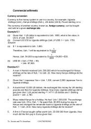
Electromagnetic Induction
Objectives: After completing this<br />
module, you should be able to:<br />
• Calculate the magnitude and direction of<br />
the induced current or emf in a conductor<br />
moving with respect to a given B-field.<br />
• Calculate the magnetic flux through an<br />
area in a given B-field.<br />
• Apply Lenz’s law and the right-hand rule<br />
to determine directions of induced emf.<br />
• Describe the operation and use of ac and<br />
dc generators or motors.
Induced Current<br />
When a conductor moves<br />
across flux lines, magnetic<br />
forces on the free electrons<br />
induce an electric current.<br />
Right-hand force rule shows<br />
current outward for down and<br />
inward for up motion. (Verify)<br />
B<br />
Down<br />
Up<br />
I<br />
I<br />
Down<br />
Up<br />
v<br />
F<br />
F<br />
v<br />
B<br />
B
Induced EMF: Observations<br />
Faraday’s observations:<br />
• Relative motion induces emf.<br />
B<br />
Flux lines F in Wb<br />
• Direction of emf depends on<br />
direction of motion.<br />
• Emf is proportional to rate at<br />
which lines are cut (v).<br />
• Emf is proportional to the<br />
number of turns N.<br />
N turns; velocityv<br />
Faraday’s Law:<br />
E=<br />
F<br />
-N<br />
t<br />
The negative sign means that E opposes its cause.
Magnetic Flux Density<br />
• Magnetic flux lines<br />
F are continuous<br />
and closed.<br />
B<br />
<br />
F<br />
A<br />
A<br />
f<br />
• Direction is that<br />
of the B vector at<br />
any point.<br />
Magnetic Flux<br />
density:<br />
When area A is<br />
perpendicular to flux:<br />
B<br />
<br />
F<br />
A<br />
; F =<br />
BA<br />
The unit of flux density is the weber per square meter.
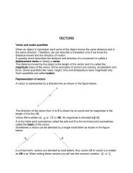
Calculating Flux When Area is<br />
Not Perpendicular to Field<br />
The flux penetrating the<br />
area A when the normal<br />
vector n makes an angle<br />
of q with the B-field is:<br />
FBAcosq<br />
a<br />
A<br />
q<br />
B<br />
n<br />
The angle q is the complement of the angle a that the<br />
plane of the area makes with B field. (Cos q = Sin a)
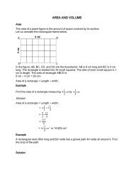
Example 1: A current loop has an area of 40 cm 2<br />
and is placed in a 3-T B-field at the given angles.<br />
Find the flux F through the loop in each case.<br />
x x x x<br />
x x x x<br />
A<br />
x x x x<br />
x x x x<br />
n<br />
n<br />
q<br />
n<br />
A = 40 cm 2 (a) q = 0 0 (b) q = 90 0 (c) q = 60 0<br />
(a) F = BA cos 0 0 = (3 T)(0.004 m 2 )(1);<br />
(b) F = BA cos 90 0 = (3 T)(0.004 m 2 )(0);<br />
F 12.0 mWb<br />
F 0 mWb<br />
(c) F = BA cos 60 0 = (3 T)(0.004 m 2 )(0.5); F 6.00 mWb
Application of Faraday’s Law<br />
Faraday’s Law:<br />
E=<br />
F<br />
-N<br />
t<br />
A change in flux F can<br />
occur by a change in area or<br />
by a change in the B-field:<br />
F = B A<br />
F = A B<br />
Rotating loop = B A<br />
n<br />
n<br />
Loop at rest = A B<br />
n
Example 2: A coil has 200 turns of area 30 cm 2 .<br />
It flips from vertical to horizontal position in a<br />
time of 0.03 s. What is the induced emf if the<br />
constant B-field is 4 mT?<br />
A = 30 cm 2 – 0 = 30 cm 2<br />
F = B A = (3 mT)(30 cm 2 )<br />
F = (0.004 T)(0.0030 m 2 )<br />
N<br />
N = 200 turns<br />
n<br />
q<br />
B<br />
S<br />
F = 1.2 x 10 -5 Wb<br />
B = 4 mT; 0 0 to 90 0<br />
E<br />
N<br />
F<br />
t<br />
-5<br />
1.2 x 10 Wb<br />
(200)<br />
0.03 s<br />
E = -0.080 V<br />
The negative sign indicates the polarity of the voltage.
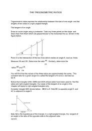
Lenz’s Law<br />
Lenz’s law: An induced current will be in such a direction<br />
as to produce a magnetic field that will oppose the<br />
motion of the magnetic field that is producing it.<br />
Induced B<br />
Left motion<br />
Induced B<br />
I<br />
Right motion<br />
I<br />
N<br />
Flux increasing to left induces<br />
loop flux to the right.<br />
S<br />
N<br />
Flux decreasing by right move<br />
induces loop flux to the left.<br />
S
Example 3: Use Lenz’s law to determine direction<br />
of induced current through R if switch is closed<br />
for circuit below (B increasing).<br />
Close switch. Then what is<br />
direction of induced current?<br />
R<br />
The rising current in right circuit causes flux to increase<br />
to the left, inducing current in left circuit that must<br />
produce a rightward field to oppose motion. Hence<br />
current I through resistor R is to the right as shown.
Directions of Forces<br />
and EMFs<br />
An emf E is induced by<br />
moving wire at velocity v<br />
in constant B field. Note<br />
direction of I.<br />
x x x x x x x x x<br />
x x x x x x I x x<br />
x x x x x x x x x<br />
x x I x x x x<br />
v<br />
x<br />
vx<br />
x x x x x Lx x x x<br />
x x x x x x x x<br />
x x x x x x x x x<br />
x<br />
From Lenz’s law, we see<br />
that a reverse field (out) is<br />
created. This field causes a<br />
leftward force on the wire<br />
that offers resistance to the<br />
motion. Use right-hand<br />
force rule to show this.<br />
I<br />
B<br />
v<br />
Induced<br />
emf<br />
x x x<br />
x x<br />
x x x<br />
x x<br />
x x x<br />
x x<br />
x x x<br />
Lenz’s law<br />
I<br />
v<br />
B
Motional EMF in a Wire<br />
Force F on charge q in wire:<br />
F = qvB; Work = FL = qvBL<br />
Work qvBL<br />
E= <br />
q q<br />
EMF:<br />
E= BLv<br />
x x x x x x<br />
I<br />
x<br />
x x x x x x<br />
x x x x x x x<br />
x x<br />
I<br />
x x x x<br />
x x x x x<br />
L<br />
x v x<br />
x x x x x x<br />
x x x x x x x<br />
x<br />
F<br />
B<br />
v<br />
If wire of length L moves with<br />
velocity v an angle q with B:<br />
E=BLv sinq<br />
v sin q<br />
B<br />
q<br />
v<br />
Induced Emf E
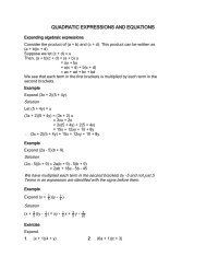
Example 4: A 0.20-m length of wire moves at<br />
a constant speed of 5 m/s in at 140 0 with a<br />
0.4-T B-Field. What is the magnitude and<br />
direction of the induced emf in the wire?<br />
E=<br />
E=BLv sinq<br />
0<br />
(0.4 T)(0.20 m)(5 m/s)sin140<br />
v<br />
q<br />
North<br />
B<br />
E = -0.257 V<br />
South<br />
Using right-hand rule, point fingers<br />
to right, thumb along velocity, and<br />
hand pushes in direction of induced<br />
emf—to the north in the diagram.<br />
v<br />
South<br />
I<br />
North<br />
B
The AC Generator<br />
• An alternating AC current is<br />
produced by rotating a loop<br />
in a constant B-field.<br />
• Current on left is outward<br />
by right-hand rule.<br />
• The right segment has an<br />
inward current.<br />
Rotating Loop in B-field<br />
B<br />
v I<br />
I<br />
v<br />
B<br />
• When loop is vertical, the<br />
current is zero.<br />
I in R is right, zero, left, and then zero as loop rotates.
Operation of AC Generator<br />
I=0<br />
I=0
Calculating Induced EMF<br />
Rectangular<br />
loop a x b<br />
Each segment a<br />
has constant<br />
velocity v.<br />
a<br />
n<br />
B<br />
b<br />
Area A = ab<br />
. n<br />
q<br />
b/2<br />
q<br />
x<br />
B<br />
v<br />
Both segments a moving with<br />
v at angle q with B gives emf:<br />
E= Bavsin q;<br />
vwr<br />
w<br />
b<br />
2<br />
E<br />
T<br />
<br />
2Ba w sinq<br />
<br />
b<br />
2<br />
<br />
E BAwsin<br />
q<br />
T<br />
v = wr<br />
q<br />
r = b/2<br />
v sin q<br />
n<br />
x<br />
q<br />
B<br />
v
Sinusoidal Current of Generator<br />
+E<br />
xx.<br />
.<br />
-E<br />
The emf varies sinusoidally with max and min emf<br />
For N turns, the EMF is:<br />
E NBAwsin<br />
q
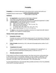
Example 5: An ac generator has 12 turns of<br />
wire of area 0.08 m 2 . The loop rotates in a<br />
magnetic field of 0.3 T at a frequency of 60<br />
Hz. Find the maximum induced emf.<br />
w = 2pf = 2p(60 Hz) = 377 rad/s<br />
Emf is maximum when q = 90 0 .<br />
E<br />
max<br />
=NBAw; Since sinq 1<br />
E =<br />
max<br />
2<br />
(12)(0.3 T)(.08 m )(377 rad/s)<br />
. n<br />
q B<br />
x<br />
f = 60 Hz<br />
The maximum emf generated is therefore:<br />
E max = 109 V<br />
If the resistance is known, then Ohm’s law (V = IR) can<br />
be applied to find the maximum induced current.
The DC Generator<br />
The simple ac generator<br />
can be converted to a dc<br />
generator by using a single<br />
split-ring commutator to<br />
reverse connections twice<br />
per revolution.<br />
Commutator<br />
E<br />
t<br />
DC Generator<br />
For the dc generator: The emf fluctuates in magnitude,<br />
but always has the same direction (polarity).
The Electric Motor<br />
In a simple electric motor, a current loop experiences a<br />
torque which produces rotational motion. Such motion<br />
induces a back emf to oppose the motion.<br />
Applied voltage – back emf<br />
= net voltage<br />
V – E b = IR<br />
Since back emf E b increases with<br />
rotational frequency, the starting<br />
current is high and the operating<br />
current is low: E b = NBAw sin q<br />
E b<br />
I<br />
V<br />
Electric Motor
Armature and Field Windings<br />
In the commercial motor,<br />
many coils of wire around<br />
the armature will produce<br />
a smooth torque. (Note<br />
directions of I in wires.)<br />
Series-Wound Motor: The<br />
field and armature wiring<br />
are connected in series.<br />
Motor<br />
Shunt-Wound Motor: The field windings and the<br />
armature windings are connected in parallel.
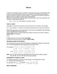
Example 6: A series-wound dc motor has an<br />
internal resistance of 3 W. The 120-V supply<br />
line draws 4 A when at full speed. What is the<br />
emf in the motor and the starting current?<br />
E b<br />
Recall that:<br />
V – E b = IR<br />
I<br />
V<br />
120 V – E b = (4 A)(3 W<br />
The back emf<br />
in motor:<br />
E b = 108 V<br />
The starting current I s is found by noting that E b = 0<br />
in beginning (armature has not started rotating).<br />
120 V – 0 = I s (3 W I s = 40 A
Summary<br />
Faraday’s Law:<br />
E=<br />
F<br />
-N<br />
t<br />
A change in flux F can<br />
occur by a change in area or<br />
by a change in the B-field:<br />
F = B A<br />
F = A B<br />
Calculating flux through an area in a B-field:<br />
B<br />
<br />
F<br />
A<br />
; F =<br />
BA<br />
FBAcosq
Summary (Cont.)<br />
Lenz’s law: An induced current will be in such a direction<br />
as to produce a magnetic field that will oppose the<br />
motion of the magnetic field that is producing it.<br />
Induced B<br />
Left motion<br />
Induced B<br />
I<br />
Right motion<br />
I<br />
N<br />
Flux increasing to left induces<br />
loop flux to the right.<br />
S<br />
N<br />
Flux decreasing by right move<br />
induces loop flux to the left.<br />
S
Summary (Cont.)<br />
An emf is induced by a wire<br />
moving with a velocity v at an<br />
angle q with a B-field.<br />
v sin q<br />
E= BLv sinq<br />
Induced Emf E<br />
In general for a coil of N turns of area A rotating<br />
with a frequency in a B-field, the generated emf<br />
is given by the following relationship:<br />
B<br />
q<br />
v<br />
For N turns, the EMF is:<br />
E NBAwsin<br />
q
Summary (Cont.)<br />
The ac generator is<br />
shown to the right. The<br />
dc generator and a dc<br />
motor are shown below:<br />
DC Generator<br />
V<br />
Electric Motor
Summary (Cont.)<br />
The rotor generates a back<br />
emf in the operation of a<br />
motor that reduces the<br />
applied voltage. The<br />
following relationship exists:<br />
Applied voltage – back emf<br />
= net voltage<br />
V – E b = IR<br />
Motor
CONCLUSION: Chapter 31A<br />
Electromagnetic Induction