H - Parker Hannifin - Solutions for the Truck Industry
H - Parker Hannifin - Solutions for the Truck Industry
H - Parker Hannifin - Solutions for the Truck Industry

Create successful ePaper yourself
Turn your PDF publications into a flip-book with our unique Google optimized e-Paper software.
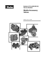
Mobile<br />
Accessory Valves<br />
Catalog HY14-2405/US
Catalog HY14-2405/US<br />
Contents<br />
catalog-cvr.p65, dd<br />
Mobile Accessory Valves<br />
Series and Description Page<br />
CFD<br />
Technical In<strong>for</strong>mation ............................................................................................................................................ 1<br />
Ordering In<strong>for</strong>mation ............................................................................................................................................. 1<br />
Dimensions ........................................................................................................................................................... 2<br />
CFDA<br />
Technical In<strong>for</strong>mation ............................................................................................................................................ 3<br />
Ordering In<strong>for</strong>mation ............................................................................................................................................. 3<br />
Dimensions ........................................................................................................................................................... 4<br />
DC25<br />
Technical In<strong>for</strong>mation ............................................................................................................................................ 5<br />
Ordering In<strong>for</strong>mation ............................................................................................................................................. 6<br />
Dimensions ........................................................................................................................................................... 6<br />
DS12, DS75<br />
Technical In<strong>for</strong>mation ............................................................................................................................................ 7<br />
Ordering In<strong>for</strong>mation ............................................................................................................................................. 7<br />
Dimensions ........................................................................................................................................................... 8<br />
DWV<br />
Technical In<strong>for</strong>mation ............................................................................................................................................ 9<br />
Ordering In<strong>for</strong>mation ............................................................................................................................................. 9<br />
Dimensions ..........................................................................................................................................................10<br />
DXV<br />
Technical In<strong>for</strong>mation ...........................................................................................................................................11<br />
Ordering In<strong>for</strong>mation ............................................................................................................................................11<br />
Dimensions ..........................................................................................................................................................12<br />
HP<br />
Technical In<strong>for</strong>mation ...........................................................................................................................................13<br />
Ordering In<strong>for</strong>mation ............................................................................................................................................14<br />
Dimensions ..........................................................................................................................................................15<br />
Per<strong>for</strong>mance Curve ..............................................................................................................................................15<br />
WARNING<br />
II<br />
Continued on next page<br />
FAILURE OR IMPROPER SELECTION OR IMPROPER USE OF THE PRODUCTS AND/OR SYSTEMS DESCRIBED HEREIN OR RELATED ITEMS CAN CAUSE DEATH,<br />
PERSONAL INJURY AND PROPERTY DAMAGE.<br />
This document and o<strong>the</strong>r in<strong>for</strong>mation from <strong>Parker</strong> <strong>Hannifin</strong> Corporation, its subsidiaries and authorized distributors provide product and/or system options <strong>for</strong> fur<strong>the</strong>r investigation by<br />
users having technical expertise. It is important that you analyze all aspects of your application and review <strong>the</strong> in<strong>for</strong>mation concerning <strong>the</strong> product or system in <strong>the</strong> current product<br />
catalog. Due to <strong>the</strong> variety of operating conditions and applications <strong>for</strong> <strong>the</strong>se products or systems, <strong>the</strong> user, through its own analysis and testing, is solely responsible <strong>for</strong> making <strong>the</strong><br />
final selection of <strong>the</strong> products and systems and assuring that all per<strong>for</strong>mance, safety and warning requirements of <strong>the</strong> application are met.<br />
The products described herein, including without limitation, product features, specifications, designs, availability and pricing, are subject to change by <strong>Parker</strong> <strong>Hannifin</strong> Corporation<br />
and its subsidiaries at any time without notice.<br />
The items described in this document are hereby offered <strong>for</strong> sale by <strong>Parker</strong> <strong>Hannifin</strong> Corporation, its subsidiaries or its authorized distributors. This offer and its acceptance are governed<br />
by <strong>the</strong> provisions stated in <strong>the</strong> "Offer of Sale".<br />
© Copyright 2005 <strong>Parker</strong> <strong>Hannifin</strong> Corporation, All Rights Reserved<br />
Offer of Sale<br />
<strong>Parker</strong> <strong>Hannifin</strong> Corporation<br />
Hydraulic Valve Division<br />
Elyria, Ohio, USA
Catalog HY14-2405/US<br />
Contents<br />
catalog-cvr.p65, dd<br />
Mobile Accessory Valves<br />
Series and Description Page<br />
LO<br />
Technical In<strong>for</strong>mation ...........................................................................................................................................16<br />
Ordering In<strong>for</strong>mation ............................................................................................................................................16<br />
Dimensions ..........................................................................................................................................................17<br />
LOA<br />
Technical In<strong>for</strong>mation ...........................................................................................................................................18<br />
Ordering In<strong>for</strong>mation ............................................................................................................................................18<br />
Dimensions ..........................................................................................................................................................19<br />
PD and PDC<br />
Technical In<strong>for</strong>mation ...........................................................................................................................................20<br />
Ordering In<strong>for</strong>mation ............................................................................................................................................20<br />
Dimensions ..........................................................................................................................................................21<br />
RPJL<br />
Technical In<strong>for</strong>mation ...........................................................................................................................................22<br />
Ordering In<strong>for</strong>mation ............................................................................................................................................22<br />
Dimensions ..........................................................................................................................................................23<br />
Per<strong>for</strong>mance Curve ..............................................................................................................................................22<br />
RPL<br />
Technical In<strong>for</strong>mation ...........................................................................................................................................24<br />
Ordering In<strong>for</strong>mation ............................................................................................................................................24<br />
Dimensions ..........................................................................................................................................................25<br />
Per<strong>for</strong>mance Curve ..............................................................................................................................................24<br />
S, H, SM and HM<br />
Technical In<strong>for</strong>mation ...........................................................................................................................................26<br />
Ordering In<strong>for</strong>mation ............................................................................................................................................27<br />
Dimensions .................................................................................................................................................. 28 - 29<br />
Per<strong>for</strong>mance Curves ............................................................................................................................................30<br />
WJL<br />
Technical In<strong>for</strong>mation ...........................................................................................................................................31<br />
Ordering In<strong>for</strong>mation ............................................................................................................................................31<br />
Dimensions ..........................................................................................................................................................32<br />
Per<strong>for</strong>mance Curves ............................................................................................................................................32<br />
Offer of Sale ...........................................................................................................................................................33<br />
III<br />
<strong>Parker</strong> <strong>Hannifin</strong> Corporation<br />
Hydraulic Valve Division<br />
Elyria, Ohio, USA
Catalog HY14-2405/US<br />
Mobile Accessory Valves<br />
Technical In<strong>for</strong>mation Series CFD<br />
General Description<br />
Series CFD flow controls are a constant volume,<br />
priority-type flow control designed <strong>for</strong> power steering.<br />
Operation<br />
Flow enters <strong>the</strong> valve through <strong>the</strong> inlet. The spool<br />
orifice size is fixed and determines flow from <strong>the</strong><br />
controlled flow port. When controlled flow demand is<br />
satisfied, <strong>the</strong> balance of <strong>the</strong> inlet flow passes through<br />
<strong>the</strong> excess flow port and returns to <strong>the</strong> tank. The<br />
excess flow port is not a work port and must not be<br />
pressurized. In addition, flow cannot be reversed<br />
through <strong>the</strong> excess flow port.<br />
Flow through <strong>the</strong> controlled port can be reversed, but it<br />
is not pressure compensated.<br />
Features<br />
•<br />
Fixed flow rate<br />
Cross drilled spool provides extremely accurate metering<br />
Hardened metering spool<br />
High tensile, cast iron body<br />
Specifications<br />
Input Flow<br />
Operating Pressure<br />
56.25 LPM (15 GPM)<br />
SAE Ports 177 Bar (2500 PSI)<br />
NPTF Ports 138 Bar (2000 PSI)<br />
Minimum<br />
Compensation<br />
Pressure<br />
3.45 Bar (50 PSI)<br />
Operating Nitrile Seals:<br />
Temperature -40°C to +93°C<br />
Range (Ambient) (-40°F to +200°F)<br />
Material Body – High strength cast iron<br />
Filtration ISO Code 16/13<br />
SAE Class 4 or better<br />
Mounting Position In-line; no restrictions<br />
CFD.p65, dd<br />
1<br />
CF<br />
Ordering In<strong>for</strong>mation<br />
CFD<br />
Constant<br />
Volume<br />
Priority Flow<br />
Control<br />
P<br />
Port Size<br />
EF<br />
Code CF Port EF Port P Port T Port<br />
10 SAE-8 SAE-10 SAE-10 3/8" NPTF<br />
50 3/8" NPTF 1/2" NPTF 1/2" NPTF 3/8" NPTF<br />
75 1/2" NPTF 3/4" NPTF 3/4" NPTF 3/8" NPTF<br />
Service Parts<br />
SAE - 10 plug 10HP50V-S<br />
SAE - 4 plug 4HP50V-S<br />
Spool Seal 3910N-7<br />
Note: The body and <strong>the</strong> internal parts are<br />
non-service items.<br />
CF EF<br />
<strong>Parker</strong> <strong>Hannifin</strong> Corporation<br />
Hydraulic Valve Division<br />
Elyria, Ohio, USA<br />
Controlled<br />
Flow<br />
Code Description<br />
1 3.75 LPM (1.0 GPM)<br />
1.5 5.63 LPM (1.5 GPM)<br />
2 7.5 LPM (2 GPM)<br />
3 11.25 LPM (3 GPM)<br />
4 15 LPM (4 GPM)<br />
5 18.75 LPM (5 GPM)<br />
P
Catalog HY14-2405/US<br />
Mobile Accessory Valves<br />
Dimensions Series CFD<br />
Inch equivalents <strong>for</strong> millimeter dimensions are shown in (**)<br />
CFD.p65, dd<br />
6.4<br />
(0.25)<br />
11.2<br />
(0.44)<br />
33.3<br />
(1.31)<br />
11.2<br />
(0.44)<br />
58.7<br />
(2.31)<br />
153.9<br />
(6.06)<br />
87.2<br />
(3.44)<br />
87.3<br />
(3.44)<br />
141.2<br />
(5.56)<br />
2<br />
11.2<br />
(0.44)<br />
33.3<br />
(1.31)<br />
79.5<br />
(3.13)<br />
Mounting Bolt Holes<br />
2 places<br />
8.81<br />
(0.35)<br />
101.6<br />
(4.00)<br />
47.8<br />
(1.88)<br />
38.1<br />
(1.50)<br />
<strong>Parker</strong> <strong>Hannifin</strong> Corporation<br />
Hydraulic Valve Division<br />
Elyria, Ohio, USA<br />
23.9<br />
(0.94)
Catalog HY14-2405/US<br />
Mobile Accessory Valves<br />
Technical In<strong>for</strong>mation Series CFDA<br />
General Description<br />
Series CFDA flow controls offer a dependable means<br />
of obtaining flow adjustment up to 56.25 LPM<br />
(15 GPM). It provides easy manual control where<br />
frequent flow change is required. Pressure compensation<br />
provides a smooth, constant output flow regardless<br />
of pressure changes at <strong>the</strong> controlled flow port.<br />
Operation<br />
Flow enters <strong>the</strong> valve through <strong>the</strong> inlet. Rotating <strong>the</strong><br />
adjusting knob varies <strong>the</strong> flow from <strong>the</strong> controlled flow<br />
port. When controlled flow demand is satisfied, <strong>the</strong><br />
balance of <strong>the</strong> inlet flow passes through <strong>the</strong> excess<br />
flow port and returns to <strong>the</strong> tank. The excess flow port<br />
is not a work port and must not be pressurized.<br />
Flow through <strong>the</strong> controlled port can be reversed, but<br />
is not pressure compensated.<br />
Features<br />
• Adjustable flow rate<br />
Cross drilled spool provides extremely accurate metering<br />
Hardened metering spool<br />
High tensile, cast iron body<br />
Specifications<br />
Input Flow<br />
Operating Pressure<br />
56.25 LPM (15 GPM)<br />
SAE Ports 177 Bar (2500 PSI)<br />
NPTF Ports 138 Bar (2000 PSI)<br />
Flow Adjustment 6 turns of knob from minimum to<br />
Range maximum flow<br />
Operating Nitrile Seals:<br />
Temperature -40°C to +93°C<br />
Range (Ambient) (-40°F to +200°F)<br />
Material Body – High strength cast iron<br />
Filtration ISO Code 16/13<br />
SAE Class 4 or better<br />
Mounting Position In-line; no restrictions<br />
CFDA.p65, dd<br />
3<br />
Ordering In<strong>for</strong>mation<br />
CFDA<br />
Pressure<br />
Compensated<br />
Bypass Type<br />
Flow Control<br />
Service Parts<br />
Port Size<br />
Knob 03236001<br />
Seal Knob Cap 3910N-7<br />
Note: The body and <strong>the</strong> internal parts are<br />
non-service items.<br />
Code Description<br />
10 SAE-10 (3/4" - 16 UNF)<br />
50 1/2" - 14 NPT<br />
75 3/4" - 14 NPT<br />
<strong>Parker</strong> <strong>Hannifin</strong> Corporation<br />
Hydraulic Valve Division<br />
Elyria, Ohio, USA
Catalog HY14-2405/US<br />
Mobile Accessory Valves<br />
Dimensions Series CFDA<br />
Inch equivalents <strong>for</strong> millimeter dimensions are shown in (**)<br />
6.4<br />
(0.25)<br />
CFDA.p65, dd<br />
11.2<br />
(0.44)<br />
33.3<br />
(1.31)<br />
141.2<br />
(5.56)<br />
58.7<br />
(2.31)<br />
87.3<br />
(3.44)<br />
Approx<br />
174.8<br />
(6.88)<br />
87.2<br />
(3.44)<br />
153.9<br />
(6.06)<br />
4<br />
11.2<br />
(0.44)<br />
33.3<br />
(1.31) 101.6<br />
(4.00)<br />
79.5<br />
(3.13)<br />
Mounting Bolt Holes<br />
2 places<br />
8.81<br />
(0.35)<br />
47.8<br />
(1.88)<br />
38.1<br />
(1.50)<br />
<strong>Parker</strong> <strong>Hannifin</strong> Corporation<br />
Hydraulic Valve Division<br />
Elyria, Ohio, USA<br />
23.9<br />
(0.94)
Catalog HY14-2405/US<br />
Mobile Accessory Valves<br />
Technical In<strong>for</strong>mation Series DC25<br />
General Description<br />
Series DC25 accessory valves are priority flow controls.<br />
They are designed <strong>for</strong> applications where<br />
two separate hydraulic circuits are to be served from<br />
a single pump. The valve provides a priority flow to<br />
<strong>the</strong> primary (CF) circuit, and an excess flow to a<br />
secondary (EF) circuit or to <strong>the</strong> tank. When <strong>the</strong> excess<br />
flow port is plugged, <strong>the</strong> valve will function as a<br />
restrictive-type, pressure compensated flow control.<br />
Features<br />
•<br />
Excess flow can be used in a secondary circuit<br />
Hardened metering spool<br />
Specifications<br />
Input Flow 112.5 LPM (30 GPM)<br />
Adjustable Controlled<br />
Flow Range 3.75-97.5 LPM (1-26 GPM)<br />
Accuracy of ± 10% @ 11.25 LPM (3 GPM)<br />
Adjustment or greater<br />
Operating Pressure SAE Ports<br />
210 Bar (3000 PSI)<br />
DC25.p65, dd<br />
NPTF Ports<br />
138 Bar (2000 PSI)<br />
Minimum<br />
Operating Pressure 4.8 Bar (70 PSI)<br />
Operating Temperature Nitrile Seals: -40°C to +93°C<br />
Range (Ambient) (-40°F to +200°F)<br />
Material Body – High strength cast iron<br />
Spool – Hardened and ground<br />
steel<br />
Filtration ISO Code 16/13, SAE Class 4<br />
or better<br />
Mounting Position In-line; no restrictions<br />
Knob Rotation 360° full adjustment<br />
5<br />
Excess Flow Controlled Flow<br />
Operation<br />
Inlet<br />
Flow enters <strong>the</strong> inlet port and passes through an<br />
adjustable control orifice. The control orifice can be<br />
varied externally in <strong>the</strong> adjustable version.<br />
Flow through <strong>the</strong> adjustable control orifice causes a<br />
pressure drop which is sensed across <strong>the</strong> compensator<br />
spool. Excess flow across <strong>the</strong> compensator spool<br />
increases <strong>the</strong> pressure drop across it. This changes<br />
<strong>the</strong> pressure drop and shifts <strong>the</strong> spool allowing it to<br />
maintain priority flow and diverting more flow to <strong>the</strong><br />
excess flow port. When pressure in <strong>the</strong> excess flow<br />
port exceeds <strong>the</strong> pressure in <strong>the</strong> controlled flow port,<br />
<strong>the</strong> spool will also shift to maintain <strong>the</strong> required priority<br />
flow to <strong>the</strong> primary circuit.<br />
If <strong>the</strong> controlled flow port is blocked, <strong>the</strong> compensator<br />
spool will return to <strong>the</strong> closed position, allowing no flow<br />
through <strong>the</strong> valve.<br />
<strong>Parker</strong> <strong>Hannifin</strong> Corporation<br />
Hydraulic Valve Division<br />
Elyria, Ohio, USA
Catalog HY14-2405/US<br />
Mobile Accessory Valves<br />
Ordering In<strong>for</strong>mation Series DC25<br />
DC25 A<br />
Priority Flow<br />
Control<br />
DC25.p65, dd<br />
Flow Control<br />
Adjustment<br />
Knob<br />
Adjustment<br />
Port Size<br />
Code Description<br />
10 SAE-10<br />
12 SAE-12<br />
50 1/2" NPTF<br />
75 3/4" NPTF<br />
Dimensions<br />
Inch equivalents <strong>for</strong> millimeter dimensions are shown in (**)<br />
#12 SAE Ports<br />
1-1/16 UN-2B Thread<br />
3 Places<br />
113.5<br />
(4.47)<br />
88.9<br />
(3.50)<br />
9.5<br />
(0.38)<br />
63.5<br />
(2.50)<br />
26.2<br />
(1.03)<br />
Inlet<br />
167.1 (6.58)<br />
.350 Diameter thru<br />
Mtg Hole - 2 Places<br />
26.2<br />
(1.03)<br />
EF CF<br />
6<br />
Service Parts<br />
Relief Valve Kits<br />
34 to 86 Bar (500 to 1250 PSI) 20089001<br />
121 to 138 Bar (1750 to 2000 PSI) 20089004<br />
138 to 179 Bar (2000 to 2600 PSI) 20089005<br />
(SAE ported<br />
valves only)<br />
179 to 207 Bar (2600 to 3000 PSI) 20089006<br />
(SAE ported<br />
valves only)<br />
Knob Kit 00712017<br />
Note: The body and <strong>the</strong> spool are not service items.<br />
61.9<br />
(2.44)<br />
35.7<br />
(1.41)<br />
<strong>Parker</strong> <strong>Hannifin</strong> Corporation<br />
Hydraulic Valve Division<br />
Elyria, Ohio, USA
Catalog HY14-2405/US<br />
Mobile Accessory Valves<br />
Technical In<strong>for</strong>mation Series DS<br />
General Description<br />
Series DS12 and DS75 accessory valves are twoposition,<br />
double selector valves. They are designed <strong>for</strong><br />
directing flow from one single hydraulic circuit to two<br />
separate hydraulic lines. This permits operation of two,<br />
double-acting cylinders with:<br />
- one four-way control valve, or<br />
- four single-acting cylinders with two three-way<br />
control valves.<br />
The valve should be operated (shifted) prior to applying<br />
pressure to it. When <strong>the</strong> spool begins to move, all<br />
ports are momentarily connected.<br />
Operation<br />
In <strong>the</strong> normal mode, pump flow can enter <strong>the</strong> valve<br />
through ei<strong>the</strong>r A or B port. The o<strong>the</strong>r port <strong>the</strong>n becomes<br />
<strong>the</strong> return port. Port A is connected to Port D;<br />
Port B is connected to Port C. When <strong>the</strong> lever is<br />
pushed in, Port A is connected to Port E; Port B is<br />
connected to Port F.<br />
Features<br />
• Chrome plated spool<br />
High-tensile cast iron body<br />
Specifications<br />
Input Flow<br />
Operating Pressure<br />
93.75 LPM (25 GPM)<br />
SAE Ports 207 Bar (3000 PSI)<br />
NPTF Ports 138 Bar (2000 PSI)<br />
Operating Temperature Nitrile Seals:<br />
Range (Ambient) -40°C to +93°C<br />
(-40°F to +200°F)<br />
Material Body – High strength cast iron<br />
Spool – Hardened and ground<br />
steel<br />
Filtration ISO Code 16/13<br />
SAE Class 4 or better<br />
Mounting Position In-line; no restrictions<br />
DS.p65, dd<br />
7<br />
C Port<br />
Ordering In<strong>for</strong>mation<br />
DS<br />
Double<br />
Selector Valve<br />
Service Parts<br />
B<br />
Port<br />
F E C D F E C D<br />
A<br />
Port<br />
Port Size<br />
B A B<br />
Code Description<br />
12 SAE 12 (1 1/16" - 12 UN)<br />
75 3/4" - 14 NPT<br />
Note: NPT pipe ports are not<br />
recommended <strong>for</strong> pressures<br />
above 138 Bar (2000 PSI)<br />
Handle Kit 06656001<br />
Kit – Spool Seals and 06492001<br />
Retaining Rings<br />
Clevis and Lock Washer Kit 08650235<br />
Note: The body and <strong>the</strong> spool are not service items.<br />
A<br />
D Port<br />
F Port E Port<br />
<strong>Parker</strong> <strong>Hannifin</strong> Corporation<br />
Hydraulic Valve Division<br />
Elyria, Ohio, USA
Catalog HY14-2405/US<br />
Mobile Accessory Valves<br />
Dimensions Series DS<br />
Inch equivalents <strong>for</strong> millimeter dimensions are shown in (**)<br />
22.4<br />
(0.88)<br />
30.2<br />
(1.19)<br />
30.2<br />
(1.19)<br />
22.4<br />
(0.88)<br />
DS.p65, dd<br />
84.1<br />
(3.31)<br />
77.7<br />
(3.06)<br />
28.7<br />
(1.13)<br />
9.7<br />
(0.38) bolts<br />
Two Mtg. holes <strong>for</strong><br />
Travel<br />
111.3<br />
(4.38)<br />
16.0<br />
(0.59)<br />
82.6<br />
(3.25)<br />
14.2<br />
(0.56)<br />
41.4<br />
(1.63)<br />
9.7<br />
(0.38)<br />
8<br />
215.9<br />
(8.50)<br />
72.1<br />
(2.84)<br />
45.2<br />
(1.78)<br />
Standard handle – may be<br />
mounted to ei<strong>the</strong>r side or in<br />
vertical position. Handle is<br />
shown in side position.<br />
Approx. overall length<br />
with lever handle<br />
144.5<br />
(5.69)<br />
C D<br />
B A<br />
F E<br />
54.1<br />
(2.13)<br />
35.8<br />
(1.41)<br />
<strong>Parker</strong> <strong>Hannifin</strong> Corporation<br />
Hydraulic Valve Division<br />
Elyria, Ohio, USA<br />
149.4<br />
(5.88)
Catalog HY14-2405/US<br />
Mobile Accessory Valves<br />
Technical In<strong>for</strong>mation Series DWV<br />
General Description<br />
Series DWV relief valves are differential area, crossover<br />
reliefs (cushion valves). They are designed to<br />
eliminate or minimize shock, surge, or overload<br />
conditions on hydraulic equipment. They may be used<br />
with cylinders of equal displacement, or with motors to<br />
provide crossover relief when <strong>the</strong> motors are stopped.<br />
Operation<br />
The DWV relief valve relieves oil from one side of <strong>the</strong><br />
actuator to tank, <strong>the</strong>re<strong>for</strong>e reducing shock and preventing<br />
overload. It also eliminates cavitation and <strong>the</strong><br />
need <strong>for</strong> a separate tank connection. The valve should<br />
be installed as close to <strong>the</strong> actuator as possible <strong>for</strong><br />
best results.<br />
Features<br />
• Compact, low profile design<br />
Fast response to cushion shocks and protect actuators<br />
Cartridge style relief valves<br />
High tensile, compacted graphite body<br />
Specifications<br />
Input Flow<br />
Operating Pressure<br />
93.75 LPM (25 GPM)<br />
SAE Ports 210 Bar (3000 PSI)<br />
NPTF Ports 138 Bar (2000 PSI)<br />
Operating Temperature Nitrile Seals:<br />
Range (Ambient) -40°C to +93°C<br />
(-40°F to +200°F)<br />
Material Body – High strength<br />
cast iron<br />
Filtration<br />
Poppet – Hardened and<br />
ground steel<br />
ISO Code 16/13<br />
SAE Class 4 or better<br />
Mounting Position In-line; no restrictions<br />
DWV.p65, dd<br />
9<br />
Ordering In<strong>for</strong>mation<br />
DWV<br />
Differential Area<br />
Crossover Relief<br />
Port Size<br />
Code Description<br />
8 SAE-8 (3/4" - 16 UNF)<br />
10 SAE-10 (7/8" - 14 UNF)<br />
12 SAE-12 (1 1/16" - 12 UNF)<br />
50 1/2" - 14 NPT<br />
75 3/4" - 14 NPT<br />
Adjustment<br />
Option<br />
<strong>Parker</strong> <strong>Hannifin</strong> Corporation<br />
Hydraulic Valve Division<br />
Elyria, Ohio, USA<br />
Pressure<br />
Range<br />
Code Setting Range<br />
1250 89 Bar (1250 PSI) 35 - 89 Bar (500 - 1250 PSI)<br />
2000 142 Bar (2000 PSI) 89 - 142 Bar (1250 - 2000 PSI)<br />
2500 177 Bar (2500 PSI) 142 - 177 Bar (2000 - 2500 PSI)<br />
3000 210 Bar (3000 PSI) 142 - 210 Bar (2000 - 3000 PSI)<br />
Service Parts<br />
Code Description<br />
Omit Shim Adjustable<br />
A Screw Adjustable<br />
Relief Valve Cartridges<br />
35 - 89 Bar (500 - 1250 PSI) WHA-1250<br />
89 - 142 Bar (1250 - 2000 PSI) WHA-2000<br />
142 - 177 Bar (2000 - 2500 PSI) WHA-2500<br />
177 - 210 Bar (2500 - 3000 PSI) WHA-3000<br />
O-Ring Seal Kit<br />
Relief Adjustments<br />
Screw Adjustment –<br />
1/4 turn = 200 PSI ±10%<br />
00712359<br />
Shim Adjustment – 100 PSI 00462001<br />
150 - 250 PSI 00459001<br />
250 - 450 PSI 00458001<br />
Note: The body and <strong>the</strong> internal parts of <strong>the</strong> relief valve<br />
(including <strong>the</strong> spring) are non-service items.
Catalog HY14-2405/US<br />
Technical In<strong>for</strong>mation<br />
Per<strong>for</strong>mance Curves<br />
Dimensions<br />
Inch equivalents <strong>for</strong> millimeter dimensions are shown in (**)<br />
DWV.p65, dd<br />
Mobile Accessory Valves<br />
Series DWV<br />
Low End – 34 to 207 Bar (500 to 3000 PSI) High End – 34 to 207 Bar (500 to 3000 PSI)<br />
Pressure<br />
PSI Bar<br />
3500 241<br />
3000 207<br />
2500 172<br />
2000 138<br />
1500 103<br />
1000<br />
500<br />
69<br />
34<br />
0<br />
LPM<br />
0<br />
GPM<br />
61.8<br />
(2.44)<br />
A<br />
A<br />
18.9 37.9 56.8 75.7<br />
5 10 15<br />
Flow<br />
20<br />
30.9<br />
(1.22)<br />
7497 Spring<br />
1870 Spring<br />
7078 Spring<br />
7638 Spring<br />
1869 Spring<br />
94.6<br />
25<br />
10<br />
Pressure<br />
22.4<br />
(0.88)<br />
PSI Bar<br />
3500 241<br />
3000 207<br />
2500 172<br />
2000 138<br />
1500 103<br />
1000<br />
500<br />
69<br />
34<br />
0<br />
LPM<br />
0<br />
GPM<br />
207.9<br />
(8.19)<br />
89.2<br />
(3.51)<br />
7497 Spring<br />
1870 Spring<br />
7078 Spring<br />
7638 Spring<br />
1869 Spring<br />
18.9 37.9 56.8 75.7<br />
5 10 15<br />
Flow<br />
20<br />
44.5<br />
(1.75)<br />
22.4<br />
(0.88)<br />
8.74<br />
(0.34)<br />
Dia. Hole (2)<br />
104.0<br />
(4.09)<br />
17.5<br />
(0.69)<br />
17.5<br />
(0.69)<br />
94.6<br />
25<br />
88.9<br />
(3.50)<br />
<strong>Parker</strong> <strong>Hannifin</strong> Corporation<br />
Hydraulic Valve Division<br />
Elyria, Ohio, USA<br />
124.0<br />
(4.88)
Catalog HY14-2405/US<br />
Mobile Accessory Valves<br />
Technical In<strong>for</strong>mation Series DXV<br />
General Description<br />
Series DXV relief valves are direct acting, crossover<br />
reliefs (cushion valves). They are designed to eliminate<br />
or minimize shock, surge, or overload conditions on<br />
hydraulic equipment. They may be used with cylinders<br />
of equal displacement, or with motors to provide<br />
crossover relief when <strong>the</strong> motors are stopped.<br />
Operation<br />
The DXV relief valve relieves oil from one side of <strong>the</strong><br />
actuator to tank, <strong>the</strong>re<strong>for</strong>e reducing shock and preventing<br />
overload. It also eliminates cavitation and <strong>the</strong><br />
need <strong>for</strong> a separate tank connection. The valve should<br />
be installed as close to <strong>the</strong> actuator as possible <strong>for</strong><br />
best results.<br />
Features<br />
• Compact, low profile design<br />
Hardened seats <strong>for</strong> long life<br />
Fast response to cushion shocks and protect actuators<br />
High tensile, compacted graphite body<br />
Specifications<br />
Input Flow<br />
Operating Pressure<br />
37.5 LPM (10 GPM)<br />
SAE Ports 210 Bar (3000 PSI)<br />
NPTF Ports 138 Bar (2000 PSI)<br />
Operating Temperature Nitrile Seals:<br />
Range (Ambient) -40°C to +93°C<br />
(-40°F to +200°F)<br />
Material Body – High strength<br />
cast iron<br />
Filtration<br />
Poppet – Hardened and<br />
ground steel<br />
ISO Code 16/13<br />
SAE Class 4 or better<br />
Mounting Position In-line; no restrictions<br />
DXV.p65, dd<br />
11<br />
Relief A<br />
Ordering In<strong>for</strong>mation<br />
DXV<br />
Direct Acting<br />
Crossover Relief<br />
Port Size<br />
Code Description<br />
8 SAE-8 (3/4" - 16 UNF)<br />
10 SAE-10 (7/8" - 14 UNF)<br />
38 3/8" - 18 NPT<br />
50 1/2" - 14 NPT<br />
75 3/4" - 14 NPT<br />
Adjustment<br />
Option<br />
<strong>Parker</strong> <strong>Hannifin</strong> Corporation<br />
Hydraulic Valve Division<br />
Elyria, Ohio, USA<br />
Pressure<br />
Range<br />
Code Setting Range<br />
400 28 Bar (400 PSI) 3.5 - 28 Bar (50 - 400 PSI)<br />
750 53 Bar (750 PSI) 28 - 53 Bar (400 - 750 PSI)<br />
900 64 Bar (900 PSI) 53 - 64 Bar (750 - 900 PSI)<br />
1300 92 Bar (1300 PSI) 64 - 92 Bar (900 - 1300 PSI)<br />
1450 103 Bar (1450 PSI) 91 - 103 Bar (1300 - 1450 PSI)<br />
1800 128 Bar (1800 PSI) 103 - 128 Bar (1450 - 1800 PSI)<br />
2000 142 Bar (2000 PSI) 128 - 142 Bar (1800 - 2000 PSI)<br />
3000* 210 Bar (3000 PSI) 142 - 210 Bar (2000 - 3000 PSI)<br />
* SAE ported bodies only.<br />
Service Parts<br />
Actuator A<br />
Actuator B<br />
Valve A Valve B<br />
Code Description<br />
Omit Shim Adjustable<br />
Upper Relief Valve Seal 2115N-7<br />
Relief Adjustments<br />
Shim Adjustment<br />
100 PSI 00462001<br />
150 - 250 PSI 00459001<br />
250 - 450 PSI 00458001<br />
Note: The body and <strong>the</strong> internal parts of <strong>the</strong> relief valve<br />
(including <strong>the</strong> spring) are non-service items.<br />
Relief B
Catalog HY14-2405/US<br />
Dimensions<br />
Inch equivalents <strong>for</strong> millimeter dimensions are shown in (**)<br />
DXV.p65, dd<br />
48.5<br />
(1.91)<br />
Mobile Accessory Valves<br />
Series DXV<br />
12<br />
101.5<br />
(4.00)<br />
25.4<br />
(1.00)<br />
138.9<br />
(5.47)<br />
50.8<br />
(2.00)<br />
25.4<br />
(1.00)<br />
8.74<br />
(0.34)<br />
Dia. Hole (2)<br />
10.1<br />
(0.40)<br />
74.7<br />
(2.94)<br />
94.7<br />
(3.73)<br />
<strong>Parker</strong> <strong>Hannifin</strong> Corporation<br />
Hydraulic Valve Division<br />
Elyria, Ohio, USA
Catalog HY14-2405/US<br />
Mobile Accessory Valves<br />
Technical In<strong>for</strong>mation Series HP<br />
General Description<br />
Series HP50 pilot pressure valves are designed to<br />
provide a separately mounted, pilot pressure system<br />
<strong>for</strong> solenoid and hydraulic remote-controlled, directional<br />
control valves.<br />
The pilot pressure valve is installed in <strong>the</strong> hydraulic<br />
system between <strong>the</strong> pump and <strong>the</strong> directional control<br />
valve.<br />
This valve can be used <strong>for</strong> o<strong>the</strong>r applications where a<br />
pilot pressure is required. Possible applications are<br />
remote-controlled, variable displacement pumps or<br />
motors and differential locks.<br />
The valve consists of a mechanical sequence valve<br />
and a pressure reducing cartridge. The pilot operated<br />
sequence valve creates a stand-by pressure greater<br />
than <strong>the</strong> pressure reducing cartridge. The pressure<br />
reducing cartridge limits <strong>the</strong> maximum pressure in <strong>the</strong><br />
pilot circuit.<br />
Features<br />
• Eliminates separate pilot pump and relief valve <strong>for</strong> a pilot<br />
system<br />
Simplifies plumbing <strong>for</strong> a pilot system<br />
Easily installed into an existing hydraulic system<br />
Optional main system relief valve available<br />
Solenoid kits available<br />
Operation<br />
The mechanical pressure build up valve can be used<br />
in open center systems where <strong>the</strong> pump is not in<br />
stand-by operation <strong>for</strong> long periods of time. Pilot<br />
pressure is maintained at all times.<br />
HP.p65, dd<br />
JOY<br />
STICK<br />
13<br />
Specifications<br />
Input Flow 187.5 LPM (50 GPM)<br />
Pilot Flow 18.75 LPM (5 GPM)<br />
Operating Pressure<br />
Inlet 240 Bar (3500 PSI)<br />
Tank 24 Bar (350 PSI)<br />
Operating Nitrile Seals:<br />
Temperature -40°C to +93°C<br />
Range (Ambient) (-40°F to +200°F)<br />
Material Body – High strength cast iron<br />
Filtration ISO Code 16/13, SAE Class 4<br />
or better<br />
Mounting Position In-line; no restrictions<br />
Understanding <strong>the</strong> HP pilot pressure valve<br />
Many open center systems have very little pressure<br />
drop through <strong>the</strong> directional valve when in <strong>the</strong> neutral<br />
position. These systems do not provide enough<br />
pressure <strong>for</strong> pilot operation. To create pilot pressure,<br />
use <strong>the</strong> HP valve.<br />
The HP valve has four basic component parts:<br />
1. Sequence valve slave<br />
2. Sequence valve pilot<br />
3. Reducing valve<br />
4. Relief valve<br />
The sequence slave (part #1) and <strong>the</strong> sequence pilot<br />
(part #2) create <strong>the</strong> back pressure that is used <strong>for</strong> pilot<br />
operation. The reducing valve (part #3) protects <strong>the</strong><br />
pilot system from high pressure. The relief valve<br />
(part #4) protects <strong>the</strong> pump. Note that <strong>the</strong> relief valve<br />
is located on <strong>the</strong> pump side of <strong>the</strong> sequence valve.<br />
<strong>Parker</strong> <strong>Hannifin</strong> Corporation<br />
Hydraulic Valve Division<br />
Elyria, Ohio, USA
Catalog HY14-2405/US<br />
Mobile Accessory Valves<br />
Ordering In<strong>for</strong>mation Series HP<br />
HP<br />
Hydraulic<br />
Pilot<br />
Pressure<br />
Valves<br />
Service Parts<br />
20.7 Bar (300 PSI) Pilot Pressure Reducing Valve 11416001<br />
34.5 Bar (500 PSI) Pilot Pressure Reducing Valve 11416002<br />
NR - no relief plug 04142003<br />
Relief Valve RP51-A<br />
Pressure Build Up Valve 20275001<br />
Upper Seal - Pressure Build Up Valve 3914V-9<br />
Lower Seal - Pressure Build Up Valve 2019N-7<br />
Lower Back Up Ring - Pressure Build Up Valve 407480<br />
12 VDC Solenoid Unloader Kit 10722001<br />
24 VDC Solenoid Unloader Kit 00711871<br />
Relief Valve Seal Kit 00712223<br />
Note: The body and <strong>the</strong> internal parts are non-service items.<br />
HP.p65, dd<br />
50<br />
Port Size<br />
Code Description<br />
Pump SAE-20 (1 5/8"-12 UNF)<br />
Valve SAE-20 (1 5/8"-12 UNF)<br />
Tank SAE-20 (1 5/8"-12 UNF)<br />
Pilot SAE-6 (9/16"-18 UNF)<br />
Gage SAE-4 (7/16"-20 UNF)<br />
Port Pressure<br />
Setting<br />
Code Description<br />
3 20.7 Bar (300 PSI)<br />
5 34.5 Bar (500 PSI)<br />
14<br />
MA<br />
Pressure<br />
Build Up<br />
Mechanically Adjustable<br />
Relief<br />
Option<br />
Code Description<br />
RPA Adjustable Relief –<br />
Pilot Operated (RP51-A)<br />
NR No Relief<br />
<strong>Parker</strong> <strong>Hannifin</strong> Corporation<br />
Hydraulic Valve Division<br />
Elyria, Ohio, USA
Catalog HY14-2405/US<br />
Mobile Accessory Valves<br />
Technical In<strong>for</strong>mation Series HP<br />
Dimensions<br />
Inch equivalents <strong>for</strong> millimeter dimensions are shown in (**)<br />
155.4<br />
(6.12)<br />
Per<strong>for</strong>mance Curve<br />
HP.p65, dd<br />
134.8<br />
(5.31)<br />
95.2<br />
(3.75)<br />
Pressure<br />
PSI<br />
50<br />
Bar<br />
3.5<br />
Nom. 0<br />
-50 -3.5<br />
0<br />
LPM<br />
0<br />
GPM<br />
106.7<br />
(4.20)<br />
67.1<br />
(2.64)<br />
15<br />
11.2<br />
(0.44)<br />
35.3<br />
(1.39)<br />
12.8<br />
(0.51)<br />
59.2<br />
(2.33)<br />
Pilot Per<strong>for</strong>mance (Nominal)<br />
3.8 7.6 11.4 15.1 18.9 22.7<br />
1 2 3<br />
Flow<br />
4 5 6<br />
47.6<br />
(1.88)<br />
26.5<br />
7<br />
50.0<br />
(1.97)<br />
62.0<br />
(2.44)<br />
87.5<br />
(3.44)<br />
44.5<br />
(1.75)<br />
30.2<br />
(1.19)<br />
<strong>Parker</strong> <strong>Hannifin</strong> Corporation<br />
Hydraulic Valve Division<br />
Elyria, Ohio, USA<br />
98.3<br />
(3.87)<br />
60.2<br />
(2.37)
Catalog HY14-2405/US<br />
Mobile Accessory Valves<br />
Technical In<strong>for</strong>mation Series LO<br />
General Description<br />
Series LO valves are single and double, pilot operated<br />
check valves. They are designed to lock a cylinder or<br />
part of a circuit without leakage, while a control valve<br />
is in a neutral position. Lock valves function as check<br />
valves, allowing flow to a cylinder and blocking reverse<br />
flow until pilot pressure is applied to unlock <strong>the</strong> circuit.<br />
This valve works best when used with a directional<br />
control valve that vents <strong>the</strong> work ports to tank when it<br />
is in a neutral mode.<br />
Operation<br />
Free flow is permitted from <strong>the</strong> valve port to <strong>the</strong> work<br />
port through <strong>the</strong> check valve. This check prevents<br />
reverse flow in <strong>the</strong> absence of pilot pressure. When<br />
adequate pilot pressure is applied at <strong>the</strong> pilot port, <strong>the</strong><br />
pilot piston unseats <strong>the</strong> check poppet permitting free<br />
flow.<br />
Features<br />
• Hardened seats<br />
Ball/Spring check valves<br />
High tensile, cast iron body<br />
Specifications<br />
Input Flow<br />
Operating Pressure<br />
93.75 LPM (25 GPM)<br />
SAE Ports 210 Bar (3000 PSI)<br />
NPTF Ports 138 Bar (2000 PSI)<br />
Pilot Ratio 3.36 to 1<br />
Operating Temperature Nitrile Seals:<br />
Range (Ambient) -40°C to +93°C<br />
(-40°F to +200°F)<br />
Material Body – High strength<br />
cast iron<br />
Filtration ISO Code 16/13<br />
SAE Class 4 or better<br />
Mounting Position In-line; no restrictions<br />
LO.p65, dd<br />
16<br />
Ordering In<strong>for</strong>mation<br />
LO<br />
Pilot Operated<br />
Check Valve<br />
Port Size<br />
Code Description<br />
10 SAE-10 (7/8" - 14 UNF)<br />
50 1/2" - 14 NPT<br />
Service Parts<br />
Check Valve 07350001<br />
Note: The body and <strong>the</strong> internal parts are<br />
non-service items.<br />
C1<br />
V1<br />
C1<br />
V1<br />
C2<br />
V2<br />
C2<br />
V2<br />
Type<br />
Single<br />
PO Check<br />
Double<br />
PO Check<br />
Code Description<br />
S Single<br />
D Double<br />
<strong>Parker</strong> <strong>Hannifin</strong> Corporation<br />
Hydraulic Valve Division<br />
Elyria, Ohio, USA
Catalog HY14-2405/US<br />
Dimensions<br />
Inch equivalents <strong>for</strong> millimeter dimensions are shown in (**)<br />
67.5<br />
(2.66)<br />
LO.p65, dd<br />
59.6<br />
(2.35)<br />
Valve Cyl<br />
28.7<br />
(1.13)<br />
134.8<br />
(5.31)<br />
119.1<br />
(4.69)<br />
57.1<br />
(2.25)<br />
Cyl<br />
1 2<br />
Valve<br />
Mobile Accessory Valves<br />
Series LO<br />
17<br />
8.74<br />
(0.34)<br />
Dia. thru 2 Places<br />
47.7<br />
(1.88)<br />
23.9<br />
(0.94)<br />
41.1<br />
(1.62)<br />
45.2<br />
(1.78)<br />
47.8<br />
(1.88)<br />
20.6<br />
(0.81)<br />
22.6<br />
(0.89)<br />
<strong>Parker</strong> <strong>Hannifin</strong> Corporation<br />
Hydraulic Valve Division<br />
Elyria, Ohio, USA<br />
95.5<br />
(3.76)
Catalog HY14-2405/US<br />
Mobile Accessory Valves<br />
Technical In<strong>for</strong>mation Series LOA<br />
General Description<br />
Series LOA valves are single and double, pilot operated<br />
check valves. They are designed to lock a<br />
cylinder or part of a circuit without leakage, while a<br />
control valve is in a neutral position. Lock valves<br />
function as check valves, allowing flow to a cylinder<br />
and blocking reverse flow until pilot pressure is applied<br />
to unlock <strong>the</strong> circuit. This valve works best when used<br />
with a directional control valve that vents <strong>the</strong> work<br />
ports to tank when it is in a neutral mode.<br />
Operation<br />
Free flow is permitted from <strong>the</strong> valve port to <strong>the</strong> work<br />
port through <strong>the</strong> check valve. This check prevents<br />
reverse flow in <strong>the</strong> absence of pilot pressure. When<br />
adequate pilot pressure is applied at <strong>the</strong> pilot port, <strong>the</strong><br />
pilot piston unseats <strong>the</strong> check poppet permitting free<br />
flow.<br />
Features<br />
• Hardened seats<br />
Ball/Spring check valves<br />
High tensile, cast iron body<br />
Specifications<br />
Input Flow<br />
Operating Pressure<br />
30 LPM (8 GPM)<br />
SAE Ports 210 Bar (3000 PSI)<br />
NPTF Ports 138 Bar (2000 PSI)<br />
Pilot Ratio 3.36 to 1<br />
Operating Temperature Nitrile Seals:<br />
Range (Ambient) -40°C to +93°C<br />
(-40°F to +200°F)<br />
Material Body – High strength<br />
cast iron<br />
Filtration ISO Code 16/13<br />
SAE Class 4 or better<br />
Mounting Position In-line; no restrictions<br />
LOA.p65, dd<br />
18<br />
Ordering In<strong>for</strong>mation<br />
LOA<br />
Cylinder<br />
Pilot Operated<br />
Check Valve<br />
Port Size<br />
Code Description<br />
6 SAE-6 (9/16" - 18 UNF)<br />
25 1/4" - 14 NPT<br />
38 3/8" - 18 NPT<br />
Service Parts<br />
C1<br />
V1<br />
C1<br />
V1<br />
C2<br />
V2<br />
C2<br />
V2<br />
Valve Valve<br />
Check Valve 04169001<br />
Note: The body and <strong>the</strong> internal parts are<br />
non-service items.<br />
Type<br />
Single<br />
PO Check<br />
Double<br />
PO Check<br />
Cylinder<br />
Code Description<br />
S Single<br />
D Double<br />
<strong>Parker</strong> <strong>Hannifin</strong> Corporation<br />
Hydraulic Valve Division<br />
Elyria, Ohio, USA
Catalog HY14-2405/US<br />
Dimensions<br />
Inch equivalents <strong>for</strong> millimeter dimensions are shown in (**)<br />
LOA.p65, dd<br />
76.2<br />
(3.00)<br />
38.1<br />
(1.50)<br />
33.3<br />
(1.31)<br />
8.74<br />
Dia.<br />
(0.34)<br />
2 Holes<br />
28.7<br />
(1.13)<br />
28.7<br />
(1.13)<br />
16.0<br />
(0.63)<br />
Mobile Accessory Valves<br />
Series LOA<br />
19<br />
74.7<br />
(2.94)<br />
69.9<br />
(2.75) 35.1<br />
(1.38)<br />
Cyl.<br />
3115<br />
Valve<br />
17.5<br />
(0.69)<br />
17.5<br />
(0.69)<br />
Cyl.<br />
USA<br />
Valve<br />
<strong>Parker</strong> <strong>Hannifin</strong> Corporation<br />
Hydraulic Valve Division<br />
Elyria, Ohio, USA
Catalog HY14-2405/US<br />
Mobile Accessory Valves<br />
Technical In<strong>for</strong>mation Series PD and PDC<br />
General Description<br />
Series PD and PDC accessory valves are pressure<br />
compensated flow dividers. They are designed <strong>for</strong><br />
applications where two separate hydraulic circuits are<br />
to be served from a single pump. The valve splits <strong>the</strong><br />
flow in three ratios between <strong>the</strong> two hydraulic lines.<br />
Flow through <strong>the</strong> series PD flow divider cannot be<br />
reversed. Flow through <strong>the</strong> PDC flow divider can be<br />
combined in <strong>the</strong> reverse direction and synchronized in<br />
both directions.<br />
Series PD and PDC flow dividers will divide <strong>the</strong> inlet<br />
flow to ±10% of <strong>the</strong> specified outlet flow when used<br />
within recommended capacities. In addition, many<br />
actuators can displace fluid different from <strong>the</strong> ratio of<br />
<strong>the</strong> divider. This can cause two actuators to ei<strong>the</strong>r lock<br />
up or become out of synch. A means of rephasing <strong>the</strong><br />
actuators is recommended.<br />
Operation<br />
As flow enters <strong>the</strong> inlet port of <strong>the</strong> PD version, it will<br />
pass through <strong>the</strong> control orifices in <strong>the</strong> interconnected<br />
spools. The flow passing through <strong>the</strong> orifices in <strong>the</strong><br />
spools creates a pressure drop which pulls <strong>the</strong> two<br />
spools away from each o<strong>the</strong>r. The flow <strong>the</strong>n passes to<br />
<strong>the</strong> two-divider outlet ports.<br />
When flow is to be combined in <strong>the</strong> PDC versions, it<br />
enters <strong>the</strong> valve through <strong>the</strong> two-divider outlet ports.<br />
The flow passes through <strong>the</strong> orifices in <strong>the</strong> spools<br />
creating a pressure drop which pushes <strong>the</strong> two spools<br />
towards each o<strong>the</strong>r. The combined flow <strong>the</strong>n passes to<br />
<strong>the</strong> inlet port. The design of <strong>the</strong> PD spool does not<br />
allow flow to combine.<br />
Features<br />
•<br />
Pressure compensated<br />
Cross drilled spool provides accurate metering<br />
High tensile, cast iron body<br />
Ordering In<strong>for</strong>mation<br />
Flow Divider<br />
Code Description<br />
PD Flow Divider<br />
PDC Flow Divider/<br />
Combiner<br />
NPT pipe ports are not<br />
recommended <strong>for</strong><br />
pressures above<br />
138 Bar (2000 PSI)<br />
Service Parts<br />
PD-PDC.p65, dd<br />
Port Size<br />
Code Description<br />
10 SAE-10 (3/4" - 16 UNF)<br />
12 SAE 12 (1 1/16" - 12 UNF)<br />
50 1/2" - 14 NPT<br />
75 3/4" - 14 NPT<br />
Note: The PDC is only<br />
available in a 50/50<br />
ratio.<br />
Ratio<br />
Code Description<br />
50 50/50<br />
60 60/40<br />
70 70/30<br />
Spool Seal 3914N-9 (2 required)<br />
Note: The body and <strong>the</strong> internal parts are non-service items.<br />
20<br />
Specifications<br />
Input Flow<br />
PD / PDC50 18.75 - 75 LPM (5 - 20 GPM)<br />
PD / PDC75 75 - 131.25 LPM (20 - 35 GPM)<br />
PD / PDC12 75 - 131.25 LPM (20 - 35 GPM)<br />
Accuracy<br />
Operating Pressure<br />
±10%<br />
SAE Ports 177 Bar (2500 PSI)<br />
NPTF Ports 138 Bar (2000 PSI)<br />
Operating Nitrile Seals:<br />
Temperature -40°C to +93°C<br />
Range (Ambient) (-40°F to +200°F)<br />
Material Body – High strength cast iron<br />
Spool – Hardened and ground steel<br />
Filtration ISO Code 16/13<br />
SAE Class 4 or better<br />
Mounting Position In-line; no restrictions<br />
Per<strong>for</strong>mance Curves<br />
In Divider Mode from Inlet to Joined Legs<br />
Pressure<br />
PSI Bar<br />
400 28<br />
300<br />
21<br />
200 14<br />
100 7<br />
0<br />
LPM<br />
0<br />
GPM<br />
Low Flow - Series PD<br />
High Flow - Series PD, PDC<br />
Low Flow - Series PDC<br />
18.9 37.9 56.8 75.7 94.6 113.6 132.5<br />
5 10 15<br />
Flow<br />
20 25 30 35<br />
<strong>Parker</strong> <strong>Hannifin</strong> Corporation<br />
Hydraulic Valve Division<br />
Elyria, Ohio, USA
Catalog HY14-2405/US<br />
Mobile Accessory Valves<br />
Dimensions Series PD and PDC<br />
Inch equivalents <strong>for</strong> millimeter dimensions are shown in (**)<br />
Series PD<br />
Standard Flow Divider<br />
Mounting Holes (3)<br />
8.74 (0.34) Dia.<br />
Series PDC<br />
Flow Divider / Combiner<br />
Mounting Holes (3)<br />
8.74 (0.34) Dia.<br />
PD-PDC.p65, dd<br />
Outlet 144.5<br />
(5.69)<br />
36.5<br />
(1.44)<br />
50.8<br />
(2.00)<br />
101.6<br />
(4.00)<br />
Inlet<br />
Outlet 139.9<br />
(5.51)<br />
36.5<br />
(1.44)<br />
50.8<br />
(2.00)<br />
Inlet<br />
36.5<br />
(1.44)<br />
36.5<br />
(1.44)<br />
101.6<br />
(4.00)<br />
Outlet<br />
Outlet<br />
21<br />
23.8<br />
(0.94)<br />
23.8<br />
(0.94)<br />
49.2<br />
(1.94)<br />
100.8<br />
(3.97)<br />
27.7<br />
(1.09)<br />
100.8<br />
(3.97)<br />
49.2<br />
(1.94)<br />
9/16" Hex<br />
47.6<br />
(1.87)<br />
25.4<br />
(1.00)<br />
45.2<br />
(1.78)<br />
47.6<br />
(1.87)<br />
45.2<br />
(1.78)<br />
25.4<br />
(1.00)<br />
<strong>Parker</strong> <strong>Hannifin</strong> Corporation<br />
Hydraulic Valve Division<br />
Elyria, Ohio, USA
Catalog HY14-2405/US<br />
Mobile Accessory Valves<br />
Technical In<strong>for</strong>mation Series RPJL<br />
General Description<br />
Series RPJL accessory valves are relief valves used<br />
<strong>for</strong> limiting <strong>the</strong> maximum pressure which can be<br />
applied to <strong>the</strong> portion of <strong>the</strong> hydraulic circuit where it is<br />
connected.<br />
Series RPJL relief valves are pilot operated, poppettype<br />
relief valves. Their best application is a main<br />
system relief where smooth consistent per<strong>for</strong>mance is<br />
required.<br />
Operation<br />
The pilot section opens when inlet pressure on <strong>the</strong><br />
RPJL relief valve exceeds <strong>the</strong> valve setting. This pilot<br />
flow creates a pressure imbalance across <strong>the</strong> main<br />
section causing <strong>the</strong> valve to open. The pilot section<br />
closes once <strong>the</strong> inlet pressure drops below <strong>the</strong> valve<br />
setting. This <strong>the</strong>n re-seats <strong>the</strong> poppet in <strong>the</strong> main valve<br />
and closes it.<br />
Features<br />
• Compact, low profile design<br />
Hardened and ground poppet<br />
High tensile, compacted graphite body<br />
Ordering In<strong>for</strong>mation<br />
RPJL A<br />
In-line Mounted<br />
Port Size<br />
Pilot-operated<br />
Relief Valve<br />
Code Description<br />
10 SAE-10 (7/8" - 14 UNF)<br />
Inlet and Outlet<br />
12 SAE 12 (1 1/16" - 12 UNF)<br />
Inlet and Outlet<br />
50 1/2" - 14 NPT<br />
75 3/4" - 14 NPT Pressure Ports<br />
1/2" - 14 NPT Tank Port<br />
Service Parts<br />
Relief Valve RP51-A-5000<br />
O-Ring Seal Kit 00712223<br />
Body Kit<br />
RPJL-10 K-WJL-10<br />
RPJL-50 K-WJL-50<br />
RPJL-75 K-WJL-75<br />
Relief Adjustment<br />
1/4 turn = 200 PSI ±10%<br />
Note: The internal parts of <strong>the</strong> relief valve<br />
(including <strong>the</strong> spring) are non-service items.<br />
RPJL.p65, dd<br />
Adjustment<br />
Option<br />
Adjustable<br />
Note: NPT pipe ports are not recommended <strong>for</strong> pressures above<br />
138 Bar (2000 PSI)<br />
A right angle flow (<strong>for</strong>mer T option) is created by plugging one<br />
of <strong>the</strong> P ports.<br />
22<br />
Specifications<br />
Input Flow<br />
Operating Pressure<br />
93.75 LPM (25 GPM)<br />
SAE Ports 350 Bar (5000 PSI)<br />
NPTF Ports 138 Bar (2000 PSI)<br />
Operating Temperature Nitrile Seals:<br />
Range (Ambient) -40°C to +93°C<br />
(-40°F to +200°F)<br />
Material Body – High strength cast iron<br />
Spool – Hardened and ground<br />
steel<br />
Filtration ISO Code 16/13<br />
SAE Class 4 or better<br />
Mounting Position In-line; no restrictions<br />
Per<strong>for</strong>mance Curves<br />
Crack – 34 to 345 Bar (500 to 5000 PSI)<br />
Pressure<br />
Tank<br />
Inlet<br />
PSI Bar<br />
5000 345<br />
4500 310<br />
4000 276<br />
3500 241<br />
3000 207<br />
2500 172<br />
2000 138<br />
1500 103<br />
1000 69<br />
500 34<br />
0<br />
LPM<br />
0<br />
GPM<br />
37.9 75.7 113.6 151.4<br />
10 20 30<br />
Flow<br />
40<br />
189.3<br />
50<br />
<strong>Parker</strong> <strong>Hannifin</strong> Corporation<br />
Hydraulic Valve Division<br />
Elyria, Ohio, USA
Catalog HY14-2405/US<br />
Dimensions<br />
Inch equivalents <strong>for</strong> millimeter dimensions are shown in (**)<br />
54.3<br />
(2.14)<br />
RPJL.p65, dd<br />
22.6<br />
(0.89)<br />
28.4<br />
(1.12)<br />
28.4<br />
(1.12)<br />
108.2<br />
(4.26)<br />
Mobile Accessory Valves<br />
Series RPJL<br />
23<br />
45.2<br />
(1.78)<br />
28.4<br />
(1.12)<br />
<strong>Parker</strong> <strong>Hannifin</strong> Corporation<br />
Hydraulic Valve Division<br />
Elyria, Ohio, USA
Catalog HY14-2405/US<br />
Mobile Accessory Valves<br />
Technical In<strong>for</strong>mation Series RPL<br />
General Description<br />
Series RPL relief valves are pilot operated, ball-type<br />
relief valves. Their best application is a main system<br />
relief where smooth consistent per<strong>for</strong>mance is required.<br />
Operation<br />
The pilot section opens when inlet pressure on <strong>the</strong><br />
RPL relief valve exceeds <strong>the</strong> valve setting. This pilot<br />
flow creates a pressure imbalance across <strong>the</strong> main<br />
section causing <strong>the</strong> valve to open. The pilot section<br />
closes once <strong>the</strong> inlet pressure drops below <strong>the</strong> valve<br />
setting. As a result, this re-seats <strong>the</strong> poppet in <strong>the</strong><br />
main valve and closes it.<br />
Features<br />
• Compact, low profile design<br />
Pilot operated <strong>for</strong> smooth, stable operation<br />
High tensile, compacted graphite body<br />
Specifications<br />
Input Flow<br />
Operating Pressure<br />
225 LPM (60 GPM)<br />
SAE Ports 350 Bar (5000 PSI)<br />
NPTF Ports 138 Bar (2000 PSI)<br />
Operating Temperature Nitrile Seals:<br />
Range (Ambient) -40°C to +93°C<br />
(-40°F to +200°F)<br />
Material Body – High strength<br />
cast iron<br />
Filtration<br />
Poppet – Hardened and<br />
ground steel<br />
ISO Code 16/13<br />
SAE Class 4 or better<br />
Mounting Position In-line; no restrictions<br />
Ordering In<strong>for</strong>mation<br />
RPL A<br />
Pilot Operated<br />
Relief Valve<br />
RPL.p65, dd<br />
Port Size<br />
Code Description<br />
12 SAE 12 (1 1/16" - 12 UN)<br />
16 SAE 16 (1 5/16" - 12 UN)<br />
75 3/4" - 14 NPT<br />
100 1" - 11 1/2 NPT<br />
Adjustment<br />
Option<br />
Adjustable<br />
24<br />
Tank<br />
Pressure<br />
Inlet<br />
Per<strong>for</strong>mance Curves<br />
Service Parts<br />
Pressure<br />
Inlet<br />
Crack – 34 to 345 Bar (500 to 5000 PSI)<br />
Pressure<br />
PSI Bar<br />
5000 345<br />
4500 310<br />
4000 276<br />
3500 241<br />
3000 207<br />
2500 172<br />
2000 138<br />
1500 103<br />
1000 69<br />
500 34<br />
0<br />
LPM<br />
0<br />
GPM<br />
37.9 75.7 113.6 151.4<br />
10 20 30<br />
Flow<br />
40<br />
Relief Valve RP60-A<br />
External Seal – relief valve 3914N-9<br />
Body Kit<br />
RPL-16 K-RPL-16<br />
RPL-75 K-RPL-75<br />
RPL-100 K-RPL-100<br />
Relief Adjustment<br />
1/4 turn = 200 PSI ±10%<br />
Note: The body and <strong>the</strong> internal parts of <strong>the</strong> relief valve<br />
(including <strong>the</strong> spring) are non-service items<br />
189.3 227.1<br />
50 60<br />
<strong>Parker</strong> <strong>Hannifin</strong> Corporation<br />
Hydraulic Valve Division<br />
Elyria, Ohio, USA
Catalog HY14-2405/US<br />
Dimensions<br />
Inch equivalents <strong>for</strong> millimeter dimensions are shown in (**)<br />
74.6<br />
(2.94)<br />
RPL.p65, dd<br />
60.4<br />
(2.38)<br />
85.9<br />
(3.38)<br />
43.0<br />
(1.69)<br />
104.6<br />
(4.12)<br />
95.3<br />
(3.75)<br />
Mobile Accessory Valves<br />
Series RPL<br />
25<br />
44.5<br />
(1.75)<br />
45.7<br />
(1.80)<br />
68.1<br />
(2.68)<br />
<strong>Parker</strong> <strong>Hannifin</strong> Corporation<br />
Hydraulic Valve Division<br />
Elyria, Ohio, USA<br />
166.7<br />
(6.56)
Catalog HY14-2405/US<br />
Mobile Accessory Valves<br />
Technical In<strong>for</strong>mation Series S, H, SM and HM<br />
General Description<br />
Series S and SM accessory valves are two-position,<br />
three way selector valves. They are designed <strong>for</strong><br />
directing flow from one single pump to one, or <strong>the</strong><br />
o<strong>the</strong>r of two separate hydraulic lines. An example of<br />
this is <strong>the</strong> operation of two single-acting cylinders,<br />
independent of each o<strong>the</strong>r.<br />
Series H and HM accessory valves are two-position,<br />
three way selector valves. They are designed to be<br />
used with a three-position, four way valve to provide a<br />
float or free-wheeling condition. Application examples<br />
include plows, loaders, and certain winches.<br />
All four versions of this valve should be shifted prior to<br />
<strong>the</strong> application of pressure. The flow <strong>for</strong>ces might<br />
make this valve difficult to shift under normal operating<br />
pressure and flow conditions.<br />
Operation<br />
Flow enters <strong>the</strong> valve at <strong>the</strong> inlet port. When <strong>the</strong> lever<br />
is pushed in, <strong>the</strong> spool shifts allowing inlet flow to<br />
reach <strong>the</strong> work port fur<strong>the</strong>st away from <strong>the</strong> lever. When<br />
<strong>the</strong> lever is pulled out, <strong>the</strong> spool shifts allowing inlet<br />
flow to reach <strong>the</strong> work port closest to <strong>the</strong> lever.<br />
Features<br />
• Pressure balanced spool<br />
Chrome plated spool<br />
High-tensile cast iron body<br />
Specifications<br />
Input Flow<br />
37.5 LPM (10 GPM) HM-8 and HM-50<br />
75 LPM (20 GPM) S-8, SM-8, S-10, S-50 and SM-50<br />
112.5 LPM (30 GPM) S-12, H-12, S-75 and H-75<br />
225 LPM (60 GPM)<br />
Operating Pressure<br />
S-16, S-100<br />
SAE Ports 207 Bar (3000 PSI)<br />
NPTF Ports 138 Bar (2000 PSI)<br />
S-H-SM-HM.p65, dd<br />
26<br />
Series S<br />
Series S and SM<br />
Series H and HM<br />
Series S and SM<br />
Series H and HM<br />
Operating Temperature Nitrile Seals:<br />
Range (Ambient) -40°C to +93°C (-40°F to +200°F)<br />
Material Body – High strength cast iron<br />
Spool – Hardened and ground<br />
steel<br />
Filtration ISO Code 16/13<br />
SAE Class 4 or better<br />
Mounting Position In-line; no restrictions<br />
<strong>Parker</strong> <strong>Hannifin</strong> Corporation<br />
Hydraulic Valve Division<br />
Elyria, Ohio, USA
Catalog HY14-2405/US<br />
Ordering In<strong>for</strong>mation<br />
Series<br />
Code Description<br />
S Circuit Selector<br />
SM Circuit Selector<br />
H Float Selector<br />
HM Float Selector<br />
The following models are not available:<br />
H-8 HM-10 SM-10<br />
H-10 HM-12 SM-12<br />
H-16 HM-16 SM-16<br />
H-50 HM-75 SM-75<br />
H-100 HM-100 SM-100<br />
All valves are shipped with a knob.<br />
Service Parts<br />
Knob Kit with Lockwasher 06645001<br />
all versions<br />
Clevis Kit 08650235<br />
Spool Seal & Retaining Ring Kit<br />
Size 12 and 75 only (H or S) 06492001<br />
Size 8, 10 and 50 only (H or S) 06490001<br />
Size 16 and 100 only (H or S) 06493001<br />
Spool Seal, Retaining Ring & 11411001<br />
Back-up Ring Kit (HM & SM Only)<br />
Note: The body and <strong>the</strong> spool are not service items.<br />
S-H-SM-HM.p65, dd<br />
Mobile Accessory Valves<br />
Series S, H, SM and HM<br />
Code Description<br />
8 SAE 8 (3/4" - 16 UNF)<br />
10 SAE 10 (7/8" - 14 UNF)<br />
12 SAE 12 (1 1/16" - 12 UN)<br />
50 1/2" - 14 NPT<br />
75 3/4" - 14 NPT<br />
100 1" - 11 1/2 NPT<br />
27<br />
Port Size<br />
<strong>Parker</strong> <strong>Hannifin</strong> Corporation<br />
Hydraulic Valve Division<br />
Elyria, Ohio, USA
Catalog HY14-2405/US<br />
Dimensions<br />
Inch equivalents <strong>for</strong> millimeter dimensions are shown in (**)<br />
Spool end tapped<br />
3/8-16 UNC<br />
16.0 (0.63) ∆P<br />
S-H-SM-HM.p65, dd<br />
Travel<br />
Mobile Accessory Valves<br />
Series S and H<br />
Ports (3X)<br />
See "How to Order"<br />
Series A B C D E F G H I J K L M N O P Q R<br />
S-50<br />
147.1<br />
(5.79)<br />
24.6<br />
(0.97)<br />
41.4<br />
(1.63)<br />
42.9<br />
(1.69)<br />
84.1<br />
(3.31)<br />
30.2<br />
(1.19)<br />
6.4<br />
(0.25)<br />
90.4<br />
(3.56)<br />
54.1<br />
(2.13)<br />
45.2<br />
(1.78)<br />
26.9<br />
(1.06)<br />
7.9<br />
(0.31)<br />
8.9<br />
(0.35)<br />
66.6<br />
(2.62)<br />
28.5<br />
(1.12)<br />
25.4<br />
(1.00)<br />
50.8<br />
(2.00)<br />
117.4<br />
(4.62)<br />
S-75<br />
168.2<br />
(6.62)<br />
28.7<br />
(1.13)<br />
53.9<br />
(2.12)<br />
52.3<br />
(2.06)<br />
101.6<br />
(4.00)<br />
38.1<br />
(1.50)<br />
6.4<br />
(0.25)<br />
111.3<br />
(4.38)<br />
76.2<br />
(3.00)<br />
55.6<br />
(2.19)<br />
38.1<br />
(1.50)<br />
9.7<br />
(0.38)<br />
8.9<br />
(0.35)<br />
66.6<br />
(2.62)<br />
28.5<br />
(1.12)<br />
25.4<br />
(1.00)<br />
58.7<br />
(2.31)<br />
138.2<br />
(5.44)<br />
S-100<br />
188.5<br />
(7.42)<br />
30.2<br />
(1.19)<br />
65.0<br />
(2.56)<br />
57.2<br />
(2.25)<br />
114.3<br />
(4.50)<br />
42.9<br />
(1.69)<br />
6.4<br />
(0.25)<br />
125.5<br />
(4.94)<br />
87.4<br />
(3.44)<br />
62.7<br />
(2.47)<br />
43.7<br />
(1.72)<br />
9.7<br />
(0.38)<br />
10.4<br />
(0.41)<br />
88.9<br />
(3.50)<br />
35.1<br />
(1.38)<br />
31.8<br />
(1.25)<br />
73.2<br />
(2.88)<br />
158.8<br />
(6.25)<br />
H-75<br />
168.2<br />
(6.62)<br />
28.7<br />
(1.13)<br />
53.9<br />
(2.12)<br />
52.3<br />
(2.06)<br />
101.6<br />
(4.00)<br />
38.1<br />
(1.50)<br />
6.4<br />
(0.25)<br />
111.3<br />
(4.38)<br />
76.2<br />
(3.00)<br />
55.8<br />
(2.19)<br />
38.1<br />
(1.50)<br />
9.7<br />
(0.38)<br />
8.9<br />
(0.35)<br />
66.6<br />
(2.62)<br />
28.5<br />
(1.12)<br />
25.4<br />
(1.00)<br />
58.7<br />
(2.31)<br />
138.2<br />
(5.44)<br />
28<br />
<strong>Parker</strong> <strong>Hannifin</strong> Corporation<br />
Hydraulic Valve Division<br />
Elyria, Ohio, USA
Catalog HY14-2405/US<br />
Dimensions<br />
Inch equivalents <strong>for</strong> millimeter dimensions are shown in (**)<br />
Series SM and HM share a<br />
common housing, but have<br />
dissimilar spools. Common<br />
dimensions are depicted while<br />
differences are charted.<br />
Series A B C<br />
SM<br />
16.0<br />
(0.63)<br />
150.4<br />
(5.92)<br />
120.7<br />
(4.75)<br />
HM<br />
10.4<br />
(0.40)<br />
140.7<br />
(5.54)<br />
111.3<br />
(4.38)<br />
S-H-SM-HM.p65, dd<br />
Spool<br />
Travel<br />
Ports – 3 Places<br />
See "How to Order"<br />
Overall<br />
Length<br />
55.6<br />
(2.19)<br />
17.5<br />
(0.69)<br />
Overall<br />
Length,<br />
Less Knob<br />
and Clevis<br />
A<br />
16.7<br />
(0.62)<br />
38.1<br />
(1.50)<br />
Mobile Accessory Valves<br />
Series SM and HM<br />
19.1<br />
(0.75)<br />
29<br />
38.1<br />
(1.50)<br />
44.5<br />
(1.75)<br />
C<br />
B<br />
Mounting Holes<br />
5/16-18 UNC – 2 Places<br />
0.97 (0.38) ∆P<br />
<strong>Parker</strong> <strong>Hannifin</strong> Corporation<br />
Hydraulic Valve Division<br />
Elyria, Ohio, USA<br />
39.6<br />
(1.56)<br />
Spool end tapped<br />
3/8-16 UNC<br />
16.0 (0.63) ∆P<br />
69.9<br />
(2.75)
Catalog HY14-2405/US<br />
Per<strong>for</strong>mance Curves<br />
Series S<br />
Pressure<br />
Pressure<br />
PSI<br />
50 Bar<br />
40<br />
30<br />
20<br />
10<br />
3<br />
2<br />
1<br />
0<br />
LPM<br />
0<br />
GPM<br />
PSI<br />
100<br />
75<br />
50<br />
25<br />
Bar<br />
6<br />
4<br />
2<br />
0<br />
LPM<br />
0<br />
GPM<br />
S-H-SM-HM.p65, dd<br />
S-50<br />
30 60 90<br />
5 10 15 20 25<br />
Flow<br />
S-75<br />
120<br />
30<br />
30 60 90 120<br />
10 20 30<br />
Flow<br />
150<br />
35 40<br />
150<br />
40<br />
S-100<br />
200<br />
50 60<br />
Note: Model S selectors will tolerate flow rates well in excess of those<br />
shown here. Consideration should be given to <strong>the</strong> restrictiveness of<br />
<strong>the</strong> port adaptors.<br />
Series H<br />
180<br />
50<br />
Mobile Accessory Valves<br />
Series S, H, SM and HM<br />
30<br />
Series SM<br />
Pressure<br />
PSI<br />
150<br />
100<br />
50<br />
Bar<br />
10<br />
6<br />
2<br />
0<br />
LPM<br />
0<br />
GPM<br />
Series HM<br />
Pressure<br />
PSI Bar<br />
500<br />
27<br />
375<br />
250 18<br />
125<br />
9<br />
0<br />
LPM<br />
0<br />
GPM<br />
10 30<br />
50<br />
5<br />
10<br />
Flow<br />
15<br />
5<br />
Flow<br />
15<br />
30<br />
70<br />
<strong>Parker</strong> <strong>Hannifin</strong> Corporation<br />
Hydraulic Valve Division<br />
Elyria, Ohio, USA<br />
20<br />
10
Catalog HY14-2405/US<br />
Mobile Accessory Valves<br />
Technical In<strong>for</strong>mation Series WJL<br />
General Description<br />
Series WJL accessory valves are relief valves used <strong>for</strong><br />
limiting <strong>the</strong> maximum pressure which can be applied<br />
to <strong>the</strong> portion of <strong>the</strong> hydraulic circuit where it is connected.<br />
Series WJL relief valves are differential poppet-type<br />
relief valves. Their best application is a cylinder port<br />
relief where fast response time is required.<br />
Operation<br />
Pressure on <strong>the</strong> inlet of <strong>the</strong> WJL relief valve acts on<br />
<strong>the</strong> differential area of <strong>the</strong> poppet (area difference<br />
between <strong>the</strong> O.D. of <strong>the</strong> poppet and <strong>the</strong> seat diameter)<br />
to produce a <strong>for</strong>ce which is opposed by <strong>the</strong> spring<br />
<strong>for</strong>ce. The poppet is pushed off its seat when pressure<br />
reaches <strong>the</strong> valve setting. The spring <strong>for</strong>ce re-seats <strong>the</strong><br />
poppet once <strong>the</strong> pressure drops below <strong>the</strong> valve<br />
setting.<br />
Features<br />
• Compact, low profile design<br />
Hardened and ground poppet<br />
High tensile, compacted graphite body<br />
Specifications<br />
Input Flow<br />
Operating Pressure<br />
93.75 LPM (25 GPM)<br />
SAE Ports 210 Bar (3000 PSI)<br />
NPTF Ports 138 Bar (2000 PSI)<br />
Operating Temperature Nitrile Seals:<br />
Range (Ambient) -40°C to +93°C<br />
(-40°F to +200°F)<br />
Material Body – High strength cast iron<br />
Spool – Hardened and ground<br />
steel<br />
Filtration ISO Code 16/13<br />
SAE Class 4 or better<br />
Mounting Position In-line; no restrictions<br />
Note: A right angle flow path (<strong>for</strong>mer T option) is created by plugging<br />
one of <strong>the</strong> P ports.<br />
Service Parts<br />
Relief Valve Cartridges<br />
35 - 89 Bar (500 - 1250 PSI) WHA-1250<br />
89 - 142 Bar (1250 - 2000 PSI) WHA-2000<br />
142 - 177 Bar (2000 - 2500 PSI) WHA-2500<br />
177 - 210 Bar (2500 - 3000 PSI) WHA-3000<br />
O-Ring Seal Kit 00712223<br />
WJL.p65, dd<br />
31<br />
Tank<br />
Inlet<br />
Ordering In<strong>for</strong>mation<br />
WJL<br />
In-line Mounted WH<br />
Differential Poppet<br />
Relief Valve<br />
Note: The internal parts of <strong>the</strong> relief valve (including <strong>the</strong> spring) are non-service items.<br />
Port Size<br />
Code Description<br />
10 SAE-10 (7/8" - 14 UNF)<br />
12 SAE 12 (1 1/16" - 12 UNF)<br />
50 1/2" - 14 NPT<br />
75 3/4" - 14 NPT Pressure Ports<br />
12" - 14 NPT Tank Port<br />
P P<br />
Note: NPT pipe ports are not recommended <strong>for</strong> pressures<br />
above 138 Bar (2000 PSI)<br />
<strong>Parker</strong> <strong>Hannifin</strong> Corporation<br />
Hydraulic Valve Division<br />
Elyria, Ohio, USA<br />
T<br />
Adjustment<br />
Option<br />
Code Description<br />
Omit Shim<br />
Adjustable<br />
A Screw<br />
Adjustable<br />
Pressure<br />
Range<br />
Code Setting Range<br />
1250 89 Bar (1250 PSI) 35 - 89 Bar (500 - 1250 PSI)<br />
2000 142 Bar (2000 PSI) 89 - 142 Bar (1250 - 2000 PSI)<br />
2500 177 Bar (2500 PSI) 142 - 177 Bar (2000 - 2500 PSI)<br />
3000 210 Bar (3000 PSI) 142 - 210 Bar (2000 - 3000 PSI)<br />
Body Kits<br />
WJL-10 K-WJL-10<br />
WJL-50 K-WJL-50<br />
WJL-75 K-WJL-75<br />
Relief Adjustments<br />
Screw Adjustment –<br />
1/4 turn = 200 PSI ±10%<br />
Shim Adjustment – 100 PSI 00462001<br />
150 - 250 PSI 00459001<br />
250 - 450 PSI 00458001
Catalog HY14-2405/US<br />
Technical In<strong>for</strong>mation<br />
Per<strong>for</strong>mance Curves<br />
Pressure<br />
PSI Bar<br />
3500 241<br />
3000 207<br />
2500 172<br />
2000 138<br />
1500 103<br />
1000<br />
500<br />
Dimensions<br />
WJL.p65, dd<br />
69<br />
34<br />
0<br />
LPM<br />
0<br />
GPM<br />
7497 Spring<br />
1870 Spring<br />
7078 Spring<br />
7638 Spring<br />
1869 Spring<br />
18.9 37.9 56.8 75.7<br />
5 10 15<br />
Flow<br />
20<br />
94.6<br />
25<br />
Mobile Accessory Valves<br />
Series WJL<br />
Low End – 34 to 207 Bar (500 to 3000 PSI) High End – 34 to 207 Bar (500 to 3000 PSI)<br />
Inch equivalents <strong>for</strong> millimeter dimensions are shown in (**)<br />
27.9<br />
(1.10)<br />
27.9<br />
(1.10)<br />
22.6<br />
(0.89)<br />
54.3<br />
(2.14)<br />
32<br />
Pressure<br />
137.8<br />
(5.43)<br />
PSI Bar<br />
3500 241<br />
3000 207<br />
2500 172<br />
2000 138<br />
1500 103<br />
1000<br />
500<br />
69<br />
34<br />
0<br />
LPM<br />
0<br />
GPM<br />
31.8<br />
(1.25)<br />
7497 Spring<br />
1870 Spring<br />
7078 Spring<br />
7638 Spring<br />
1869 Spring<br />
18.9 37.9 56.8 75.7<br />
5 10 15<br />
Flow<br />
20<br />
45.2<br />
(1.78)<br />
28.4<br />
(1.12)<br />
94.6<br />
25<br />
<strong>Parker</strong> <strong>Hannifin</strong> Corporation<br />
Hydraulic Valve Division<br />
Elyria, Ohio, USA
Catalog HY14-2405/US<br />
Offer of Sale<br />
The items described in this document and o<strong>the</strong>r documents or descriptions provided by <strong>Parker</strong> <strong>Hannifin</strong> Corporation, its subsidiaries and its authorized<br />
distributors are hereby offered <strong>for</strong> sale at prices to be established by <strong>Parker</strong> <strong>Hannifin</strong> Corporation, its subsidiaries and its authorized distributors. This<br />
offer and its acceptance by any customer ("Buyer") shall be governed by all of <strong>the</strong> following Terms and Conditions. Buyer’s order <strong>for</strong> any such items,<br />
when communicated to <strong>Parker</strong> <strong>Hannifin</strong> Corporation, its subsidiary or an authorized distributor ("Seller") verbally or in writing, shall constitute acceptance<br />
of this offer.<br />
1. Terms and Conditions of Sale: All descriptions, quotations, proposals,<br />
offers, acknowledgments, acceptances and sales of Seller’s products<br />
are subject to and shall be governed exclusively by <strong>the</strong> terms and<br />
conditions stated herein. Buyer’s acceptance of any offer to sell is limited<br />
to <strong>the</strong>se terms and conditions. Any terms or conditions in addition to, or<br />
inconsistent with those stated herein, proposed by Buyer in any acceptance<br />
of an offer by Seller, are hereby objected to. No such additional,<br />
different or inconsistent terms and conditions shall become part of <strong>the</strong><br />
contract between Buyer and Seller unless expressly accepted in writing<br />
by Seller. Seller’s acceptance of any offer to purchase by Buyer is<br />
expressly conditional upon Buyer’s assent to all <strong>the</strong> terms and conditions<br />
stated herein, including any terms in addition to, or inconsistent with those<br />
contained in Buyer’s offer, Acceptance of Seller’s products shall in all<br />
events constitute such assent.<br />
2. Payment: Payment shall be made by Buyer net 30 days from <strong>the</strong> date<br />
of delivery of <strong>the</strong> items purchased hereunder. Amounts not timely paid<br />
shall bear interest at <strong>the</strong> maximum rate permitted by law <strong>for</strong> each month<br />
or portion <strong>the</strong>reof that <strong>the</strong> Buyer is late in making payment. Any claims by<br />
Buyer <strong>for</strong> omissions or shortages in a shipment shall be waived unless<br />
Seller receives notice <strong>the</strong>reof within 30 days after Buyer’s receipt of <strong>the</strong><br />
shipment.<br />
3. Delivery: Unless o<strong>the</strong>rwise provided on <strong>the</strong> face hereof, delivery shall<br />
be made F.O.B. Seller’s plant. Regardless of <strong>the</strong> method of delivery,<br />
however, risk of loss shall pass to Buyer upon Seller’s delivery to a carrier.<br />
Any delivery dates shown are approximate only and Seller shall have no<br />
liability <strong>for</strong> any delays in delivery.<br />
4. Warranty: Seller warrants that <strong>the</strong> items sold hereunder shall be free<br />
from defects in material or workmanship <strong>for</strong> a period of 18 months from<br />
date of shipment from <strong>Parker</strong> <strong>Hannifin</strong> Corporation. THIS WARRANTY<br />
COMPRISES THE SOLE AND ENTIRE WARRANTY PERTAINING TO<br />
ITEMS PROVIDED HEREUNDER. SELLER MAKES NO OTHER WAR-<br />
RANTY, GUARANTEE, OR REPRESENTATION OF ANY KIND WHAT-<br />
SOEVER. ALL OTHER WARRANTIES, INCLUDING BUT NOT LIM-<br />
ITED TO, MERCHANTABILITY AND FITNESS FOR PURPOSE,<br />
WHETHER EXPRESS, IMPLIED, OR ARISING BY OPERATION OF<br />
LAW, TRADE USAGE, OR COURSE OF DEALING ARE HEREBY<br />
DISCLAIMED. NOTWITHSTANDING THE FOREGOING, THERE<br />
ARE NO WARRANTIES WHATSOEVER ON ITEMS BUILT OR AC-<br />
QUIRED WHOLLY OR PARTIALLY, TO BUYER’S DESIGNS OR<br />
SPECIFICATIONS.<br />
5. Limitation Of Remedy: SELLER’S LIABILITY ARISING FROM OR<br />
IN ANY WAY CONNECTED WITH THE ITEMS SOLD OR THIS CON-<br />
TRACT SHALL BE LIMITED EXCLUSIVELY TO REPAIR OR RE-<br />
PLACEMENT OF THE ITEMS SOLD OR REFUND OF THE PURCHASE<br />
PRICE PAID BY BUYER, AT SELLER’S SOLE OPTION. IN NO EVENT<br />
SHALL SELLER BE LIABLE FOR ANY INCIDENTAL, CONSEQUEN-<br />
TIAL OR SPECIAL DAMAGES OF ANY KIND OR NATURE WHATSO-<br />
EVER, INCLUDING BUT NOT LIMITED TO LOST PROFITS ARISING<br />
FROM OR IN ANY WAY CONNECTED WITH THIS AGREEMENT OR<br />
ITEMS SOLD HEREUNDER, WHETHER ALLEGED TO ARISE FROM<br />
BREACH OF CONTRACT, EXPRESS OR IMPLIED WARRANTY, OR<br />
IN TORT, INCLUDING WITHOUT LIMITATION, NEGLIGENCE, FAIL-<br />
URE TO WARN OR STRICT LIABILITY.<br />
6. Changes, Reschedules and Cancellations: Buyer may request to<br />
modify <strong>the</strong> designs or specifications <strong>for</strong> <strong>the</strong> items sold hereunder as well<br />
as <strong>the</strong> quantities and delivery dates <strong>the</strong>reof, or may request to cancel all<br />
or part of this order, however, no such requested modification or cancellation<br />
shall become part of <strong>the</strong> contract between Buyer and Seller unless<br />
accepted by Seller in a written amendment to this Agreement. Acceptance<br />
of any such requested modification or cancellation shall be at<br />
Seller’s discretion, and shall be upon such terms and conditions as Seller<br />
may require.<br />
7. Special Tooling: A tooling charge may be imposed <strong>for</strong> any special<br />
tooling, including without limitation, dies, fixtures, molds and patterns,<br />
acquired to manufacture items sold pursuant to this contract. Such special<br />
tooling shall be and remain Seller’s property notwithstanding payment of<br />
any charges by Buyer. In no event will Buyer acquire any interest in<br />
apparatus belonging to Seller which is utilized in <strong>the</strong> manufacture of <strong>the</strong><br />
items sold hereunder, even if such apparatus has been specially converted<br />
or adapted <strong>for</strong> such manufacture and notwithstanding any charges<br />
training.p65, dd<br />
33<br />
paid by Buyer. Unless o<strong>the</strong>rwise agreed, Seller shall have <strong>the</strong> right to alter,<br />
discard or o<strong>the</strong>rwise dispose of any special tooling or o<strong>the</strong>r property in its<br />
sole discretion at any time.<br />
8. Buyer’s Property: Any designs, tools, patterns, materials, drawings,<br />
confidential in<strong>for</strong>mation or equipment furnished by Buyer or any o<strong>the</strong>r<br />
items which become Buyer’s property, may be considered obsolete and<br />
may be destroyed by Seller after two (2) consecutive years have elapsed<br />
without Buyer placing an order <strong>for</strong> <strong>the</strong> items which are manufactured using<br />
such property, Seller shall not be responsible <strong>for</strong> any loss or damage to<br />
such property while it is in Seller’s possession or control.<br />
9. Taxes: Unless o<strong>the</strong>rwise indicated on <strong>the</strong> face hereof, all prices and<br />
charges are exclusive of excise, sales, use, property, occupational or like<br />
taxes which may be imposed by any taxing authority upon <strong>the</strong> manufacture,<br />
sale or delivery of <strong>the</strong> items sold hereunder. If any such taxes must<br />
be paid by Seller or if Seller is liable <strong>for</strong> <strong>the</strong> collection of such tax, <strong>the</strong><br />
amount <strong>the</strong>reof shall be in addition to <strong>the</strong> amounts <strong>for</strong> <strong>the</strong> items sold. Buyer<br />
agrees to pay all such taxes or to reimburse Seller <strong>the</strong>re<strong>for</strong>e upon receipt<br />
of its invoice. If Buyer claims exemption from any sales, use or o<strong>the</strong>r tax<br />
imposed by any taxing authority, Buyer shall save Seller harmless from<br />
and against any such tax, toge<strong>the</strong>r with any interest or penalties <strong>the</strong>reon<br />
which may be assessed if <strong>the</strong> items are held to be taxable.<br />
10. Indemnity For Infringement of Intellectual Property Rights: Seller<br />
shall have no liability <strong>for</strong> infringement of any patents, trademarks, copyrights,<br />
trade dress, trade secrets or similar rights except as provided in this<br />
Part 10. Seller will defend and indemnify Buyer against allegations of<br />
infringement of U.S. Patents, U.S. Trademarks, copyrights, trade dress<br />
and trade secrets (hereinafter ‘Intellectual Property Rights’). Seller will<br />
defend at its expense and will pay <strong>the</strong> cost of any settlement or damages<br />
awarded in an action brought against Buyer based on an allegation that<br />
an item sold pursuant to this contract infringes <strong>the</strong> Intellectual Property<br />
Rights of a third party. Seller’s obligation to defend and indemnify Buyer<br />
is contingent on Buyer notifying Seller within ten (10) days after Buyer<br />
becomes aware of such allegations of infringement, and Seller having sole<br />
control over <strong>the</strong> defense of any allegations or actions including all<br />
negotiations <strong>for</strong> settlement or compromise. If an item sold hereunder is<br />
subject to a claim that it infringes <strong>the</strong> Intellectual Property Rights of a third<br />
party, Seller may, at its sole expense and option, procure <strong>for</strong> Buyer <strong>the</strong><br />
right to continue using said item, replace or modify said item so as to make<br />
it noninfringing, or offer to accept return of said item and return <strong>the</strong><br />
purchase price less a reasonable allowance <strong>for</strong> depreciation. Notwithstanding<br />
<strong>the</strong> <strong>for</strong>egoing, Seller shall have no liability <strong>for</strong> claims of infringement<br />
based on in<strong>for</strong>mation provided by Buyer, or directed to items<br />
delivered hereunder <strong>for</strong> which <strong>the</strong> designs are specified in whole or part<br />
by Buyer, or infringements resulting from <strong>the</strong> modification, combination or<br />
use in a system of any item sold hereunder. The <strong>for</strong>egoing provisions of<br />
this Part 10 shall constitute Seller’s sole and exclusive liability and Buyer’s<br />
sole and exclusive remedy <strong>for</strong> infringement of Intellectual Property Rights.<br />
If a claim is based on in<strong>for</strong>mation provided by Buyer or if <strong>the</strong> design <strong>for</strong> an<br />
item delivered hereunder is specified in whole or in part by Buyer, Buyer<br />
shall defend and indemnify Seller <strong>for</strong> all costs, expenses or judgments<br />
resulting from any claim that such item infringes any patent, trademark,<br />
copyright, trade dress, trade secret or any similar right.<br />
11. Force Majeure: Seller does not assume <strong>the</strong> risk of and shall not be<br />
liable <strong>for</strong> delay or failure to per<strong>for</strong>m any of Seller’s obligations by reason<br />
of circumstances beyond <strong>the</strong> reasonable control of Seller (hereinafter<br />
‘Events of Force Majeure’). Events of Force Majeure shall include without<br />
limitation, accidents, acts of God, strikes or labor disputes, acts, laws,<br />
rules or regulations of any government or government agency, fires,<br />
floods, delays or failures in delivery of carriers or suppliers, shortages of<br />
materials and any o<strong>the</strong>r cause beyond Seller’s control.<br />
12. Entire Agreement/Governing Law: The terms and conditions set<br />
<strong>for</strong>th herein, toge<strong>the</strong>r with any amendments, modifications and any<br />
different terms or conditions expressly accepted by Seller in writing, shall<br />
constitute <strong>the</strong> entire Agreement concerning <strong>the</strong> items sold, and <strong>the</strong>re are<br />
no oral or o<strong>the</strong>r representations or agreements which pertain <strong>the</strong>reto. This<br />
Agreement shall be governed in all respects by <strong>the</strong> law of <strong>the</strong> State of Ohio.<br />
No actions arising out of <strong>the</strong> sale of <strong>the</strong> items sold hereunder or this<br />
Agreement may be brought by ei<strong>the</strong>r party more than two (2) years after<br />
<strong>the</strong> cause of action accrues.<br />
9/91-P<br />
<strong>Parker</strong> <strong>Hannifin</strong> Corporation<br />
Hydraulic Valve Division<br />
Elyria, Ohio, USA
Catalog HY14-2405/US<br />
<strong>Parker</strong> Hydraulics International Sales Offices<br />
North America<br />
Hydraulics Group<br />
Headquarters<br />
6035 Parkland Boulevard<br />
Cleveland, OH 44124-4141 USA<br />
Tel: 216-896-3000<br />
Fax: 216-896-4031<br />
Motion & Control Sales Division<br />
651 Robbins Drive PO Box 3500<br />
Troy, MI 48007-3500 USA<br />
Tel: 248-589-2400<br />
Fax: 248-577-4890<br />
Motion & Control Sales<br />
Division – Canada<br />
8485 Parkhill Drive<br />
Milton, Ontario L9T 5E9 Canada<br />
Tel: 905-693-3000<br />
Fax: 905-876-0788<br />
Mobile Sales<br />
Mobile Systems Division<br />
595 Schelter Road<br />
Suite 100<br />
Lincolnshire, IL 60069 USA<br />
Tel: 847-821-1500<br />
Fax: 847-821-7600<br />
Pacific Region<br />
16655 Noyes Avenue<br />
Irvine, CA 92606 USA<br />
Tel: 949-660-7033<br />
Fax: 949-852-9577<br />
Great Plains Region<br />
931 Alice Court<br />
St. Charles, IL 60174 USA<br />
Tel: 630-377-0271<br />
Fax: 630-377-0271<br />
Midwest Region<br />
4494 32nd Street<br />
Grinnell, IA 50112 USA<br />
Tel: 641-236-3694<br />
Fax: 641-236-8884<br />
Sou<strong>the</strong>rn Region<br />
2300 Bush Circle<br />
Carrollton, TX 75007 USA<br />
Tel: 972-307-2949<br />
Fax: 972-307-9410<br />
Eastern Region<br />
100 Corporate Drive<br />
Lebanon, NJ 08833 USA<br />
Tel: 610-330-0970<br />
Fax: 925-396-6481<br />
sales.p65, dd<br />
Industrial Sales<br />
Great Lakes Region<br />
3700 Embassy Parkway<br />
Suite 260<br />
Fairlawn, OH 44333 USA<br />
Tel: 330-670-2680<br />
Fax: 330-670-2681<br />
Sou<strong>the</strong>rn Region<br />
1225 Old Alpharetta Road<br />
Suite 290<br />
Alpharetta, GA 30005 USA<br />
Tel: 770-619-9767<br />
Fax: 770-619-9806<br />
Chicago Region<br />
1163 E. Ogden Avenue<br />
Suite 705, #358<br />
Naperville, IL 60563 USA<br />
Tel: 630-964-0796<br />
Fax: 866-473-9274<br />
Pacific Region<br />
16655 Noyes Avenue<br />
Irvine, CA 92606 USA<br />
Tel: 949-660-7033<br />
Fax: 949-852-9577<br />
Eastern Region<br />
100 Corporate Drive<br />
Lebanon, NJ 08833 USA<br />
Tel: 908-236-4121<br />
Fax: 908-236-4146<br />
Europe<br />
Europe Hydraulics Group<br />
<strong>Parker</strong> <strong>Hannifin</strong> Corporation<br />
<strong>Parker</strong> House<br />
55 Maylands Avenue<br />
Hemel Hempstead, Herts<br />
HP2 4SJ England<br />
Tel: 44 1442 458000<br />
Fax: 44 1442 458085<br />
Austria<br />
<strong>Parker</strong> <strong>Hannifin</strong> GmbH<br />
Badener Strasse 12<br />
A-2700 Wiener Neustadt, Austria<br />
Tel: 43 2622 23501-96<br />
Fax: 43 2622 23501-977<br />
Belgium<br />
<strong>Parker</strong> <strong>Hannifin</strong> SA NV<br />
Parc Industriel Sud, Zone II<br />
Rue du Bosquet 23<br />
B-1400 Nivelles, Belgium<br />
Tel: 32 67 280900<br />
Fax: 32 67 280999<br />
Czech Republic<br />
<strong>Parker</strong> <strong>Hannifin</strong> s.r.o.<br />
Prumyclova zona Kecany<br />
250 67 Klecany, Czech Republic<br />
Tel: 420 24 083 111<br />
Denmark<br />
<strong>Parker</strong> <strong>Hannifin</strong> Denmark A/S<br />
Industriparken 37<br />
2750 Ballerup, Denmark<br />
Tel: 45 43 56 04 00<br />
Fax: 45 43 73 31 07<br />
Europe<br />
Finland<br />
<strong>Parker</strong> <strong>Hannifin</strong> Oy<br />
Ylästöntie 16<br />
FIN-01510 Vantaa, Finland<br />
Tel: 358 9 476 731<br />
Fax: 358 9 4767 3200<br />
France<br />
<strong>Parker</strong> <strong>Hannifin</strong> France SAS<br />
142, rue de la Foret<br />
74130 Contamine sur Arve, France<br />
Tel: 33 450 25 80 25<br />
Fax: 33 450 25 24 25<br />
Germany<br />
<strong>Parker</strong> <strong>Hannifin</strong> GmbH<br />
Gutenbergstrasse 38<br />
41564 Kaarst, Germany<br />
Tel: 49 (0)2131 4016 0<br />
Fax: 49 (0)2131 4016 9199<br />
Greece<br />
<strong>Parker</strong> <strong>Hannifin</strong> Corporation<br />
A<strong>the</strong>ns Representative Office<br />
197 Syngrou Av.<br />
171 21 Nea Smyrni, A<strong>the</strong>ns, Greece<br />
Tel: 0030 210 933-6450<br />
Fax: 0030 210 933-6451<br />
Hungary<br />
<strong>Parker</strong> <strong>Hannifin</strong> Corporation<br />
Hungarian Trade Representative Office<br />
H-1149 Budapest<br />
Egressy u. 100, Hungary<br />
Tel: 36 12204155<br />
Fax: 36 14221525<br />
Ireland<br />
<strong>Parker</strong> <strong>Hannifin</strong> Ireland Ltd.<br />
Blackthorn Close,<br />
Stillorgan Industrial Park<br />
Blackrock, Co Dublin, Ireland<br />
Tel: 353 1 293 9999<br />
Fax 353 1 293 9900<br />
Italy<br />
<strong>Parker</strong> <strong>Hannifin</strong> S.p.A.<br />
Via Privata Archimede 1<br />
20094 Corsico (MI), Italy<br />
Tel: 39 02 451921<br />
Fax: 39 02 4479340<br />
The Ne<strong>the</strong>rlands<br />
<strong>Parker</strong> <strong>Hannifin</strong> B.V.<br />
Edisonstraat 1<br />
7570 AT Oldenzaal, The Ne<strong>the</strong>rlands<br />
Tel: 31 541 585000<br />
Fax: 31 541 585459<br />
Norway<br />
<strong>Parker</strong> <strong>Hannifin</strong> A/S<br />
Berghagan<br />
PO Box 3008<br />
N-1402 Ski, Norway<br />
Tel: 47 64 911000<br />
Fax: 47 64 911090<br />
(continued on next page)<br />
<strong>Parker</strong> <strong>Hannifin</strong> Corporation<br />
Hydraulic Valve Division<br />
Elyria, Ohio, USA<br />
9/04
Catalog HY14-2405/US<br />
<strong>Parker</strong> Hydraulics International Sales Offices<br />
Europe<br />
Poland<br />
<strong>Parker</strong> <strong>Hannifin</strong> Sp z.o.o.<br />
ul. Parowcowa 8B<br />
PL 02-445 Warsaw, Poland<br />
Tel: 48 22 8634942<br />
Fax: 48 22 8634944<br />
Portugal<br />
<strong>Parker</strong> <strong>Hannifin</strong> Portugal, Lda.<br />
Travessa da Bataria 184 R/C<br />
Dto./1 Esq.<br />
Leca da Palmeiraj-4450-625, Portugal<br />
Tel: 351 22 9997360<br />
Fax: 351 22 9961527<br />
Romania<br />
Hidro Consulting Impex SRL<br />
Bucaresti <strong>Parker</strong> Representative Office<br />
Bld. Ferdinand nr. 27 Sect. 2<br />
703131 Bucarest, Romania<br />
Tel: 40 21 2521382<br />
Fax: 40 21 2523381<br />
Russia<br />
<strong>Parker</strong> <strong>Hannifin</strong> Corporation<br />
Trekhrudniy Pereulok 9, bld.2<br />
Office 106<br />
123001 Moscow, Russia<br />
Tel: 7 095 234 00 54<br />
Fax: 7 095 234 05 28<br />
Slovenia<br />
<strong>Parker</strong> <strong>Hannifin</strong> Corporation<br />
Vel. Bucna vas 7<br />
SI-8000 Novo Mesto, Slovenia<br />
Tel: 386 7337 6650<br />
Fax: 386 7337 6651<br />
Spain<br />
<strong>Parker</strong> <strong>Hannifin</strong> España SA<br />
Parque Industrial Las Monjas<br />
Calle Estaciones 8<br />
28850 Torrejón de Ardoz<br />
Madrid, Spain<br />
Tel: 34 91 6757300<br />
Fax: 34 91 6757711<br />
Sweden<br />
<strong>Parker</strong> <strong>Hannifin</strong> AB<br />
Fagerstagatan 51<br />
Box 8314<br />
SE-163 08 Spånga, Sweden<br />
Tel: 46 (0)8 59 79 5000<br />
Fax: 46 (0)8 59 79 5110<br />
United Kingdom<br />
<strong>Parker</strong> <strong>Hannifin</strong> GB Ltd.<br />
Tachbrook Drive Park<br />
Tachbrook Drive<br />
Warwick, CV34 6TU, England<br />
Tel: 44 1926 317878<br />
Fax: 44 1926 317855<br />
Middle East<br />
United Arab Emirates<br />
<strong>Parker</strong> <strong>Hannifin</strong> Corporation<br />
PO Box 46451<br />
Abu Dhabi, United Arab Emirates<br />
Tel: 971 2 6788587<br />
Fax: 971 2 6793812<br />
sales.p65, dd<br />
Asia Pacific<br />
Australia Headquarters<br />
<strong>Parker</strong> <strong>Hannifin</strong> Pty Ltd.<br />
9 Carrington Road<br />
Castle Hill, NSW 2154, Australia<br />
Tel: 612 9634 7777<br />
Fax: 612 9842 5111<br />
China<br />
<strong>Parker</strong> <strong>Hannifin</strong> Beijing Office<br />
Suite B9-11, 21/F, Hanwei Plaza<br />
No. 7 Guanghua Road<br />
Chaoyang District<br />
Beijing, 100004, China<br />
Tel: 86 10 6561 0520<br />
Fax: 86 10 6561 0526<br />
<strong>Parker</strong> <strong>Hannifin</strong> Shanghai Office<br />
Room 1101, Peregrine Plaza<br />
1325 Huai Hai Road (M)<br />
Shanghai 200031, China<br />
Tel: 86 21 6445 9339<br />
Fax: 86 21 6445 9717<br />
Hong Kong<br />
<strong>Parker</strong> <strong>Hannifin</strong> Hong Kong Ltd.<br />
8/F Kin Yip Plaza<br />
9 Cheung Yee Street<br />
Cheung Sha Wan, Hong Kong<br />
Tel: 852 2428 8008<br />
Fax: 852 2480 4256<br />
India<br />
<strong>Parker</strong> <strong>Hannifin</strong> India Pvt Ltd.<br />
Plot No. EL-26, TTC Indl Area<br />
Mahape, Navi Mumbai 400 709, India<br />
Tel: 91 22 55907081-85<br />
Fax 91 22 55907080<br />
Japan<br />
<strong>Parker</strong> <strong>Hannifin</strong> Japan Ltd.<br />
Shirokanedai Building 2nd floor<br />
3-2-10, Shirokanedai<br />
Minato-ku<br />
Tokyo 108-0071, Japan<br />
Tel: 81 3 6408 3900<br />
Fax: 81 3 5449 7201<br />
Korea Headquarters<br />
<strong>Parker</strong> <strong>Hannifin</strong> Corporation<br />
777 Jung-ri, Dongtan-myeon<br />
Hwaseong-city<br />
Kyunggi-do, 445-813, Korea<br />
Tel: 82 31 379 2200<br />
Fax: 82 31 377 9710<br />
<strong>Parker</strong> Pannifin Korea Ltd.<br />
Daehwa Venture Plaza, 6F<br />
169 Samsung-Dong<br />
Kangnam-ku, Seoul, 135-090, Korea<br />
Tel: 82 2 559 0400<br />
Fax: 82 2 556 8187<br />
Singapore<br />
<strong>Parker</strong> <strong>Hannifin</strong> Singapore<br />
No. 11, Fourth Chin Bee Road<br />
619702 Jurong Town, Singapore<br />
Tel: 65 6887 6300<br />
Fax: 65 265 5125<br />
Asia Pacific<br />
Taiwan<br />
<strong>Parker</strong> <strong>Hannifin</strong> Taiwan Co., Ltd.<br />
No. 40, Wuchiuan 3rd Rd.,<br />
Wuku Industrial Park<br />
Taipei County, Taiwan 248, R.O.C.<br />
Tel: 886 2 22988987<br />
Fax: 886 2 22988982<br />
Thailand<br />
<strong>Parker</strong> <strong>Hannifin</strong> Thailand Co., Ltd.<br />
1023, 3rd floor, TPS building<br />
Pattanakarn Road, Suanluang<br />
Bangkok 10250, Thailand<br />
Tel: 662 717 8140<br />
Fax: 662 717 8148<br />
Latin America<br />
Pan American Division<br />
7400 N. W. 19th Street, Suite A<br />
Miami, FL 33126 USA<br />
Tel: 305-470-8800<br />
Fax: 305-470-8808<br />
Argentina<br />
<strong>Parker</strong> <strong>Hannifin</strong> Argentina SAIC<br />
Stephenson 2711 esq. Costa Rica<br />
1667 Tortuguitas<br />
Buenos Aires, Argentina<br />
Tel: 54 3327 44 4129<br />
Fax: 54 3327 44 4199<br />
Brazil<br />
Hydraulics Division<br />
<strong>Parker</strong> <strong>Hannifin</strong> Ind. e Com. Ltd.a.<br />
Av. Frederico Ritter, 1100<br />
Cachoeirinha RS, 94930-000 Brazil<br />
Tel: 55 51 470 9144<br />
Fax: 55 51 470 6909<br />
Chile<br />
<strong>Parker</strong> <strong>Hannifin</strong> Chile Ltd.a.<br />
Av. Americo Vespucio 2760-E<br />
Conchali - Santiago, Chile<br />
Tel: 56-2-623-1216<br />
Fax: 56-2-623-1421<br />
Venezuela<br />
<strong>Parker</strong> <strong>Hannifin</strong> de Venezuela, S.A.<br />
Av. Principal con calle Miraima<br />
Edificio Draza<br />
Boleita Norte<br />
Caracas, Venezuela<br />
Tel: 58 212 238 5422<br />
Fax: 58 212 239 2272<br />
South Africa<br />
<strong>Parker</strong> <strong>Hannifin</strong> Africa Pty Ltd.<br />
<strong>Parker</strong> Place<br />
10 Berne Avenue Aeroport<br />
P.O. Box 1153<br />
Kempton Park 1620,<br />
Republic of South Africa<br />
Tel: 27 11 9610700<br />
Fax: 27 11 3927213<br />
<strong>Parker</strong> <strong>Hannifin</strong> Corporation<br />
Hydraulic Valve Division<br />
Elyria, Ohio, USA<br />
5/02
About <strong>Parker</strong> <strong>Hannifin</strong> Corporation<br />
<strong>Parker</strong> <strong>Hannifin</strong> is a leading global motion-control<br />
company dedicated to delivering premier customer<br />
service. A Fortune 500 corporation listed on <strong>the</strong> New<br />
York Stock Exchange (PH), our components and systems<br />
comprise over 1,400 product lines that control<br />
motion in some 1,000 industrial and aerospace markets.<br />
<strong>Parker</strong> is <strong>the</strong> only manufacturer to offer its<br />
customers a choice of hydraulic, pneumatic, and<br />
electromechanical motion-control solutions. Our Company<br />
has <strong>the</strong> largest distribution network in its field,<br />
with over 7,500 distributors serving nearly<br />
400,000 customers worldwide.<br />
The Aerospace Group is<br />
a leader in <strong>the</strong> development,<br />
design, manufacture and servicing<br />
of control systems and<br />
components <strong>for</strong> aerospace and<br />
related high-technology markets,<br />
while achieving growth<br />
through premier customer<br />
service.<br />
The Fluid Connectors<br />
Group designs, manufactures<br />
and markets rigid and flexible<br />
connectors, and associated<br />
products used in pneumatic<br />
and fluid systems.<br />
The Hydraulics Group<br />
designs, produces and markets<br />
a full spectrum of hydraulic<br />
components and systems to<br />
builders and users of industrial<br />
and mobile machinery and<br />
equipment.<br />
The Automation Group<br />
is a leading supplier of pneumatic<br />
and electromechanical<br />
components and systems to<br />
automation customers worldwide.<br />
<strong>Parker</strong> <strong>Hannifin</strong> Corporation<br />
6035 Parkland Blvd.<br />
Cleveland, Ohio 44124-4141<br />
Telephone: (216) 896-3000<br />
Fax: (216) 896-4000<br />
www.parker.com<br />
<strong>Parker</strong> <strong>Hannifin</strong> Corporation<br />
<strong>Parker</strong>’s Charter<br />
To be a leading worldwide manufacturer of components<br />
and systems <strong>for</strong> <strong>the</strong> builders and users of durable goods.<br />
More specifically, we will design, market and manufacture<br />
products controlling motion, flow and pressure.<br />
We will achieve profitable growth through premier<br />
customer service.<br />
Product In<strong>for</strong>mation<br />
North American customers seeking product in<strong>for</strong>mation,<br />
<strong>the</strong> location of a nearby distributor, or repair<br />
services will receive prompt attention by calling <strong>the</strong><br />
<strong>Parker</strong> Product In<strong>for</strong>mation Center at our toll-free<br />
number: 1-800-C-PARKER (1-800-272-7537). In Europe,<br />
call 00800-C-PARKER-H (00800-2727-5374).<br />
The Climate & Industrial<br />
Controls Group designs,<br />
manufactures and markets system-control<br />
and fluid-handling<br />
components and systems to<br />
refrigeration, air-conditioning<br />
and industrial customers<br />
worldwide.<br />
The Seal Group designs,<br />
manufactures and distributes<br />
industrial and commercial<br />
sealing devices and related<br />
products by providing<br />
superior quality and total<br />
customer satisfaction.<br />
The Filtration Group<br />
designs, manufactures and<br />
markets quality filtration and<br />
clarification products, providing<br />
customers with <strong>the</strong> best<br />
value, quality, technical support,<br />
and global availability.<br />
The Instrumentation<br />
Group is a global leader in<br />
<strong>the</strong> design, manufacture and<br />
distribution of high-quality<br />
critical flow components <strong>for</strong><br />
worldwide process instrumentation,<br />
ultra-high-purity, medical<br />
and analytical applications.<br />
6/99
Catalog HY14-3201/US Hydraulic Valve Division<br />
DIN Slip-In Cartridge Valves Elyria, Ohio, USA<br />
Tel: (440) 366-5200<br />
Fax: (440) 366-5253<br />
Catalog 2400/US Hydraulic Valve Division<br />
Mobile Hydraulic Valves Elyria, Ohio, USA<br />
Tel: (440) 366-5200<br />
Fax: (440) 366-5253<br />
Catalog HY14-2502/US Hydraulic Valve Division<br />
Industrial Hydraulic Valves Elyria, Ohio, USA<br />
Tel: (440) 366-5200<br />
Fax: (440) 366-5253<br />
Catalog HY14-2550/US Hydraulic Valve Division<br />
Electrohydraulic Elyria, Ohio, USA<br />
Motion Control Products Tel: (440) 366-5200<br />
Fax: (440) 366-5253<br />
<strong>Parker</strong> <strong>Hannifin</strong> Corporation<br />
Hydraulic Valve Division<br />
520 Ternes Avenue<br />
Elyria, Ohio 44035 USA<br />
Tel: (440) 366-5200<br />
Fax: (440) 366-5253<br />
www.parker.com/hydraulicvalve<br />
Catalog HY14-2405/US,<br />
7.5M, 1/05, RRD
2/2/2005 Mobile Accessory Valve<br />
Conversion and Changes<br />
OLD PART OLD NEW PART DESCRIPTION<br />
NUMBER DESCRIPTION NUMBER CHANGE<br />
CFD-10-10-NR FLOW CONTROL NO RELIEF NO LONGER OFFERED NONE<br />
CFD-10-2 FLOW CONTROL 500-1500PSI NO LONGER OFFERED USE CFD-10-2<br />
CFD-10-2-HP FLOW CONTROL 1500-2500PSI NO LONGER OFFERED USE CFD-10-2<br />
CFD-10-2-HP-200 FLOW CONTROL 2000PSI NO LONGER OFFERED USE CFD-10-2<br />
CFD-10-6-HP FLOW CONTROL 1500-2500PSI NO LONGER OFFERED NONE<br />
CFD-10-7-NR FLOW CONTROL NO RELIEF NO LONGER OFFERED NONE<br />
CFD-50-2-NR FLOW CONTROL NO RELIEF CFD-50-2 CFD-50-2-NR<br />
CFD-50-3 FLOW CONTROL 500-1500PSI NO LONGER OFFERED USE CFD-10-3<br />
CFD-50-3-HP FLOW CONTROL 1500-2500PSI NO LONGER OFFERED USE CFD-10-3<br />
CFD-50-4 FLOW CONTROL 500-1500PSI NO LONGER OFFERED USE CFD-50-4<br />
CFD-50-4-HP FLOW CONTROL 1500-2500PSI NO LONGER OFFERED USE CFD-50-4<br />
CFD-50-5 FLOW CONTROL 500-1500PSI NO LONGER OFFERED USE CFD-50-5<br />
CFD-50-5-HP FLOW CONTROL 1500-2500PSI NO LONGER OFFERED USE CFD-50-5<br />
CFD-75-2-HP FLOW CONTROL 1500-2500PSI NO LONGER OFFERED USE CFD-75-2<br />
CFD-75-4-HP FLOW CONTROL 1500-2500PSI NO LONGER OFFERED USE CFD-75-4<br />
CFD-75-5-HP FLOW CONTROL 1500-2500PSI NO LONGER OFFERED USE CFD-75-5<br />
CFD-75-5-NR FLOW CONTROL NO RELIEF CFD-75-5 CFD-75-5-NR<br />
CFD-75-6 FLOW CONTROL 500-1500PSI NO LONGER OFFERED NONE<br />
CFD-75-6-HP FLOW CONTROL 1500-2500PSI NO LONGER OFFERED NONE<br />
CFD-75-7-HP FLOW CONTROL 1500-2500PSI NO LONGER OFFERED NONE<br />
00984625 CFD-10-1-HP 2000PSI NO LONGER OFFERED USE CFD-10-1<br />
00984781 CFD-10-2-HP 1500-2500PSI NO LONGER OFFERED USE CFD-10-2<br />
00983661 CFD-10-3-HP 2000PSI NO LONGER OFFERED USE CFD-10-3<br />
07261101 CFD-10-4-HP 1500-2500PSI NO LONGER OFFERED USE CFD-10-4<br />
07261108 CFD-10-6-HP 1500-2500PSI NO LONGER OFFERED NONE<br />
07261001 CFD-50-1.5 500-1500PSI NO LONGER OFFERED USE CFD-50-1.5<br />
08650687 CFD-50-1.5-HP 2000PSI NO LONGER OFFERED USE CFD-50-1.5<br />
00983228 CFD-50-10-HP 1500-2500PSI NO LONGER OFFERED NONE<br />
07261004 CFD-50-2-HP 1500-2500PSI NO LONGER OFFERED USE CFD-50-2<br />
07261106 CFD-50-2-NR CFD-50-2 07261106<br />
07261005 CFD-50-3 500-1500PSI NO LONGER OFFERED USE CFD-50-3<br />
07261006 CFD-50-3-HP 1500-2500PSI NO LONGER OFFERED USE CFD-50-3<br />
07261059 CFD-50-4 500-1500PSI NO LONGER OFFERED USE CFD-50-4<br />
08650686 CFD-50-4-HP 2000PSI NO LONGER OFFERED USE CFD-50-4<br />
07261009 CFD-50-4-HP 1500-2500PSI NO LONGER OFFERED USE CFD-50-4<br />
07261007 CFD-50-4-NR CFD-50-4 07261007<br />
07261011 CFD-50-5 500-1500PSI NO LONGER OFFERED USE CFD-50-5<br />
07261012 CFD-50-5-HP 1500-2500PSI NO LONGER OFFERED USE CFD-50-5<br />
07261010 CFD-50-5-NR CFD-50-5 07261010<br />
07261013 CFD-50-6 500-1500PSI NO LONGER OFFERED NONE<br />
07261017 CFD-50-8 500-1500PSI NO LONGER OFFERED NONE<br />
07261105 CFD-75-1.5 NR CFD-75-1.5 USE CFD-75-1.5<br />
00983349 CFD-75-10-NR NO LONGER OFFERED NONE<br />
07261026 CFD-75-2-HP 1500-2500PSI NO LONGER OFFERED USE CFD-75-2<br />
07261029 CFD-75-3-HP 1500-2500PSI NO LONGER OFFERED USE CFD-75-3<br />
00983561 CFD-75-3-NR CFD-75-3 00983561<br />
08650685 CFD-75-4-HP 2000PSI NO LONGER OFFERED USE CFD-75-4<br />
07261031 CFD-75-4-HP 1500-2500PSI NO LONGER OFFERED USE CFD-75-4<br />
07261032 CFD-75-5-NR CFD-75-5 07261032<br />
Page 1 of 10<br />
<strong>Parker</strong> Hydraulic Valve Division<br />
Elyria, Ohio 44035
2/2/2005 Mobile Accessory Valve<br />
Conversion and Changes<br />
OLD PART OLD NEW PART DESCRIPTION<br />
NUMBER DESCRIPTION NUMBER CHANGE<br />
07261037 CFD-75-6-HP 1500-2500PSI NO LONGER OFFERED NONE<br />
08650684 CFD-75-8-HP 2000PSI NO LONGER OFFERED NONE<br />
07261040 CFD-75-8-NR NO LONGER OFFERED NONE<br />
CFDA-10 FLOW CONTROL ADJUSTABLE CFDA-10 FLOW CONTROL ADJUSTABLE<br />
CFDA-50 FLOW CONTROL ADJUSTABLE CFDA-50 FLOW CONTROL ADJUSTABLE<br />
CFDA-75 FLOW CONTROL ADJUSTABLE CFDA-75 FLOW CONTROL ADJUSTABLE<br />
CFDA-L-10 FLOW CONTROL ADJ LOCKING CFDA-10 FLOW CONTROL ADJUSTABLE<br />
CFDA-L-50 FLOW CONT ADJ LOCKING CFDA-50 FLOW CONTROL ADJUSTABLE<br />
CFDA-L-75 FLOW CONT ADJ LOCKING CFDA-75 FLOW CONTROL ADJUSTABLE<br />
07261089 CFDA-10 CFDA-10 07261089<br />
07261052 CFDA-50 CFDA-50 07261052<br />
07261054 CFD-A-75 CFDA-75 07261054<br />
07261109 CFDA-L-10 NO LONGER OFFERED USE CFDA-10<br />
07261053 CFDA-L-50 NO LONGER OFFERED USE CFDA-50<br />
07261055 CFDA-L-75 NO LONGER OFFERED USE CFDA-75<br />
CFQ-A-10 FLOW CONTROL ADJUSTABLE NO LONGER OFFERED NONE<br />
CFQ-A-12 FLOW CONTROL ADJUSTABLE NO LONGER OFFERED NONE<br />
CFQ-A-38-R FLOW CONTROL ADJUSTABLE NO LONGER OFFERED NONE<br />
CFQ-A-50 FLOW CONTROL ADJUSTABLE NO LONGER OFFERED NONE<br />
CFQ-A-50-R FLOW CONTROL ADJUSTABLE NO LONGER OFFERED NONE<br />
CFQ-A-75 FLOW CONTROL ADJUSTABLE NO LONGER OFFERED NONE<br />
CFQ-A-75-R FLOW CONTROL ADJUSTABLE NO LONGER OFFERED NONE<br />
CFQ-A-12-R FLOW CONTROL ADJUSTABLE NO LONGER OFFERED NONE<br />
CFQ-A-8 FLOW CONTROL ADJUSTABLE NO LONGER OFFERED NONE<br />
CFQ-A-38 FLOW CONTROL ADJUSTABLE NO LONGER OFFERED NONE<br />
CFQ-A-10-R FLOW CONTROL ADJUSTABLE NO LONGER OFFERED NONE<br />
00984648 CFQ-A-10 NO LONGER OFFERED NONE<br />
00984647 CFQ-A-10-R NO LONGER OFFERED NONE<br />
00984642 CFQ-A-12 NO LONGER OFFERED NONE<br />
00984641 CFQ-A-12-R NO LONGER OFFERED NONE<br />
00984652 CFQ-A-38 NO LONGER OFFERED NONE<br />
00984651 CFQ-A-38-R NO LONGER OFFERED NONE<br />
00984646 CFQ-A-50 NO LONGER OFFERED NONE<br />
00984645 CFQ-A-50-R NO LONGER OFFERED NONE<br />
00984319 CFQ-A-75 NO LONGER OFFERED NONE<br />
00984318 CFQ-A-75-R NO LONGER OFFERED NONE<br />
00984654 CFQ-A-8 NO LONGER OFFERED NONE<br />
08387057 DC25A-10-0-NR DC25-A-10 08387057<br />
00984673 DC25A-10-0-R 1750-2000PSI NO LONGER OFFERED USE DC25-A-10<br />
00982998 DC25A-10-0-R 2000-2600PSI NO LONGER OFFERED USE DC25-A-10<br />
08387003 DC25A-12-0-NR DC25-A-12 08387003<br />
08387004 DC25A-12-0-R 500-1250PSI NO LONGER OFFERED USE DC25-A-12<br />
08650424 DC25A-12-0-R 1250-1750PSI NO LONGER OFFERED USE DC25-A-12<br />
00983772 DC25A-12-0-R 2000-2600PSI NO LONGER OFFERED USE DC25-A-12<br />
08387010 DC25A-50-0-NR DC25-A-50 08387010<br />
00983732 DC25A-50-0-R 1250-1750PSI NO LONGER OFFERED USE DC25-A-50<br />
Page 2 of 10<br />
<strong>Parker</strong> Hydraulic Valve Division<br />
Elyria, Ohio 44035
2/2/2005 Mobile Accessory Valve<br />
Conversion and Changes<br />
OLD PART OLD NEW PART DESCRIPTION<br />
NUMBER DESCRIPTION NUMBER CHANGE<br />
08387011 DC25A-50-0-R 2000-2600PSI NO LONGER OFFERED USE DC25-A-50<br />
08387009 DC25A-75-0-NR DC25-A-75 08387009<br />
00983989 DC25A-75-0-R 500-1250PSI NO LONGER OFFERED USE DC25-A-75<br />
08650425 DC25A-75-0-R 1250-1750PSI NO LONGER OFFERED USE DC25-A-75<br />
08387012 DC25A-75-0-R 1751-2000PSI NO LONGER OFFERED USE DC25-A-75<br />
00983504 DC25A-75-0-R 2000-2600PSI NO LONGER OFFERED USE DC25-A-75<br />
30100-07 DC25N-10-10-R-2500 NO LONGER OFFERED USE DC25-A-10<br />
00984259 DC25N-12-1.5-R1250-1750PS NO LONGER OFFERED NONE<br />
00984114 DC25N-12-2-NR NO LONGER OFFERED USE DC25-A-12<br />
00983157 DC25N-12-4-NR NO LONGER OFFERED USE DC25-A-12<br />
08387055 DC25N-12-6-NR NO LONGER OFFERED USE DC25-A-12<br />
00983200 DC25N-12-8-R 1750-2000PSI NO LONGER OFFERED USE DC25-A-12<br />
00984115 DC25N-75-10-R 500-1250PSI NO LONGER OFFERED USE DC25-A-75<br />
00984991 DC25N-75-13-NR NO LONGER OFFERED USE DC25-A-75<br />
08387019 DC25N-75-3-NR NO LONGER OFFERED USE DC25-A-75<br />
DC25N-12-12-R-200 FLOW CONTROL 2000-2600PSI NO LONGER OFFERED USE DC25-A-12<br />
DC25N-12-8-R-260 FLOW CONTROL 2600-3000PSI NO LONGER OFFERED USE DC25-A-12<br />
DC25A-75-0-NR PRIORITY TYPE FLOW CONTR. DC25-A-75 USE DC25A-75<br />
DC25A-12-0-NR PRIORITY TYPE FLOW CONTR. DC25-A-12 USE DC25A-12<br />
DC25N-12-6-NR PRIORITY TYPE FLOW CONTR. NO LONGER OFFERED USE DC25-A-12<br />
00983547 DS-12 W/DETENT & W/HANDLE NO LONGER OFFERED USE DS-12<br />
00983834 DS-12 W/KNOB NO LONGER OFFERED USE DS-12<br />
00984082 DS-12 W/QUAD SEALS LESS H NO LONGER OFFERED USE DS-12<br />
00983774 DS-12 W/SPECIAL TEST NO LONGER OFFERED USE DS-12<br />
07255008 DS-12 WITH HANDLE ASS'Y DS-12 07255008<br />
07255010 DS-12-LCHA NO LONGER OFFERED USE DS-12<br />
07255018 DS-12-LHO NO LONGER OFFERED USE DS-12<br />
00984479 DS-16 W/HANDLE NO LONGER OFFERED USE DS-12<br />
07255012 DS-16-LCHA NO LONGER OFFERED USE DS-12<br />
07255014 DS-71 NO LONGER OFFERED USE DS-75<br />
07255021 DS-75 W/KNOB NO LONGER OFFERED USE DS-75<br />
07255026 DS-75 WITH HANDLE ASS'Y DS-75 07255026<br />
07255023 DS-75-LCHA NO LONGER OFFERED USE DS-75<br />
07255020 DS-75-LHO NO LONGER OFFERED USE DS-75<br />
00983858 DS-75-S L/HANDLE NO LONGER OFFERED USE DS-75<br />
00983146 DS-75-W/DENT W/HANDLE NO LONGER OFFERED USE DS-75<br />
DWV-50-125 CUSHION VALVE NO LONGER OFFERED USE DWV-50-A-1250<br />
DWV-50-1750 CUSHION VALVE NO LONGER OFFERED USE DWV-50-A-2000<br />
DWV-50-200 CUSHION VALVE NO LONGER OFFERED USE DWV-50-A-2000<br />
DWV-50-2000 CUSHION VALVE NO LONGER OFFERED USE DWV-50-A-2000<br />
DWV-50-A-050 CUSHION VALVE NO LONGER OFFERED USE DWV-50-A-1250<br />
DWV-50-A-125 CUSHION VALVE NO LONGER OFFERED USE DWV-50-A-1250<br />
DWV-8-A-300 CUSHION VALVE NO LONGER OFFERED USE DWV-8-A-3000<br />
DWV-12-125 CUSHION VALVE NO LONGER OFFERED USE DWV-12-A-1250<br />
DWV-75-1750 CUSHION VALVE NO LONGER OFFERED USE DWV-75-A-2000<br />
DWV-75-2000 CUSHION VALVE NO LONGER OFFERED USE DWV-75-A-2000<br />
DWV-75-A-250 CUSHION VALVE NO LONGER OFFERED USE DWV-75-A-2000<br />
Page 3 of 10<br />
<strong>Parker</strong> Hydraulic Valve Division<br />
Elyria, Ohio 44035
2/2/2005 Mobile Accessory Valve<br />
Conversion and Changes<br />
OLD PART OLD NEW PART DESCRIPTION<br />
NUMBER DESCRIPTION NUMBER CHANGE<br />
00984406 DWV-10 1250-1749PSI NO LONGER OFFERED USE DWV-10-A-2000<br />
03744040 DWV-10 2000-2599PSI NO LONGER OFFERED USE DWV-10-A-3000<br />
03744062 DWV-10 3000-3500PSI NO LONGER OFFERED USE DWV-10-A-3000<br />
03744053 DWV-10-A 2000-2599PSI NO LONGER OFFERED USE DWV-10-A-3000<br />
30100-28 DWV-10-A/N-1250/2250 PSI NO LONGER OFFERED USE DWV-10-A-2000<br />
00983801 DWV-12 500-1249PSI NO LONGER OFFERED USE DWV-12-A-1250<br />
00984417 DWV-12 1250-1749PSI NO LONGER OFFERED USE DWV-12-A-2000<br />
03744012 DWV-12 1750-1999PSI NO LONGER OFFERED USE DWV-12-A-2000<br />
03744047 DWV-12 2000-2599PSI NO LONGER OFFERED USE DWV-12-A-2500<br />
03744059 DWV-12 2501-3000PSI NO LONGER OFFERED USE DWV-12-A-3000<br />
03744063 DWV-12-A 1750-1999PSI NO LONGER OFFERED USE DWV-12-A-2000<br />
03744032 DWV-12-A 2000-2599PSI NO LONGER OFFERED USE DWV-12-A-2500<br />
08650411 DWV-50 1350PSI NO LONGER OFFERED USE DWV-50-A-2000<br />
08650412 DWV-50 1750PSI NO LONGER OFFERED USE DWV-50-A-2000<br />
08650413 DWV-50 2000PSI DWV-50-A-2000 08650413<br />
03744008 DWV-50 500-1249PSI DWV-50-A-1250 03744008<br />
03744009 DWV-50 1250-1749PSI DWV-50-A-2000 03744009<br />
03744010 DWV-50 1750-1999PSI DWV-50-A-2000 03744010<br />
03744011 DWV-50 2000-2599PSI NO LONGER OFFERED USE DWV-50-A-2000<br />
03744021 DWV-50-A 500-1249PSI DWV-50-A-1250 03744021<br />
03744028 DWV-50-A 1250-1749PSI DWV-50-A-2000 03744028<br />
03744037 DWV-50-A 1750-1999PSI NO LONGER OFFERED USE DWV-50-A-2000<br />
03744045 DWV-50-A 2000-2599PSI NO LONGER OFFERED USE DWV-10-A-3000<br />
08650415 DWV-75 1750PSI NO LONGER OFFERED USE DWV-75-A-2000<br />
08650416 DWV-75 2000PSI NO LONGER OFFERED USE DWV-75-A-2000<br />
03744003 DWV-75 500-1249PSI NO LONGER OFFERED USE DWV-75-A-1250<br />
03744004 DWV-75 1250-1749PSI NO LONGER OFFERED USE DWV-75-A-2000<br />
03744005 DWV-75 1750-1999PSI NO LONGER OFFERED USE DWV-75-A-2000<br />
03744006 DWV-75 2000-2599PSI NO LONGER OFFERED USE DWV-12-A-3000<br />
03744061 DWV-75 2501-3200PSI NO LONGER OFFERED USE DWV-12-A-3000<br />
00983346 DWV-75-A 500-1249PSI DWV-75-A-1250 00983346<br />
03744015 DWV-75-A 1250-1749PSI NO LONGER OFFERED USE DWV-75-A-2000<br />
03744034 DWV-75-A 1750-1999PSI DWV-75-A-2000 03744034<br />
03744039 DWV-75-A 2000-2599PSI NO LONGER OFFERED USE DWV-12-A-3000<br />
00984020 DWV-75-A 2501-3000PSI NO LONGER OFFERED USE DWV-12-A-3000<br />
03744029 DWV-8 500-1249PSI NO LONGER OFFERED USE DWV-8-A-1250<br />
03744060 DWV-8 1250-1749PSI NO LONGER OFFERED USE DWV-8-A-2000<br />
03744002 DWV-8 2000-2599PSI NO LONGER OFFERED USE DWV-8-A-3000<br />
50801033 DWV-8-A 1250-1749PSI DWV-8-A-2000 50801033<br />
00983785 DWV-8-A 1750-1999PSI NO LONGER OFFERED USE DWV-8-A-2000<br />
DXV-50-1300 CUSHION VALVE DXV-50-A-1300 NONE<br />
DXV-50-150 CUSHION VALVE DXV-50-A-1800 NONE<br />
DXV-50-2000 CUSHION VALVE DXV-50-A-2000 NONE<br />
DXV-10-2500 CUSHION VALVE POP USE DXV-50-A-3000<br />
08650404 DXV-10 2500PSI POP USE DXV-10-A-3000<br />
07595082 DXV-10 401-750PSI POP USE DXV-10-A-750<br />
00983996 DXV-10 700/2500PSI POP USE DXV-10-A-750/3000<br />
07595074 DXV-10 901-1300PSI POP USE DXV-10-A-1300<br />
Page 4 of 10<br />
<strong>Parker</strong> Hydraulic Valve Division<br />
Elyria, Ohio 44035
2/2/2005 Mobile Accessory Valve<br />
Conversion and Changes<br />
OLD PART OLD NEW PART DESCRIPTION<br />
NUMBER DESCRIPTION NUMBER CHANGE<br />
07595047 DXV-10 1451-1800PSI POP USE DXV-10-A-1800<br />
07595030 DXV-10 1801-2000PSI POP USE DXV-10-A-2000<br />
07595103 DXV-10 2001-3000PSI POP USE DXV-10-A-3000<br />
07595094 DXV-38 751-900PSI DXV-38-A-900 07595094<br />
07595020 DXV-38 1301-1450PSI DXV-38-A-1450 07595020<br />
07595006 DXV-38 1451-1800PSI DXV-38-A-1800 07595006<br />
07595021 DXV-38 1801-2000PSI DXV-38-A-2000 07595021<br />
07595022 DXV-38 2001-3000PSI POP USE DXV-38-A-3000<br />
08650405 DXV-50 1300PSI POP USE DXV-50-A-1300<br />
08650406 DXV-50 1800PSI POP USE DXV-50-A-1800<br />
08650407 DXV-50 2000PSI POP USE DXV-50-A-2000<br />
07595017 DXV-50 50-400PSI DXV-50-A-400 07595017<br />
07595011 DXV-50 401-750PSI DXV-50-A-750 07595011<br />
07595010 DXV-50 751-900PSI DXV-50-A-900 07595010<br />
00983280 DXV-50 750/1500PSI POP USE DXV-50-A-1450<br />
07595003 DXV-50 901-1300PSI DXV-50-A-1300 07595003<br />
07595028 DXV-50 1301-1450PSI DXV-50-A-1450 07595028<br />
07595002 DXV-50 1451-1800PSI DXV-50-A-1800 07595002<br />
00983189 DXV-50 1500/2500PSI POP USE DXV-10-A-1800/3000<br />
07595009 DXV-50 1801-2000PSI DXV-50-A-2000 07595009<br />
07595004 DXV-50 2001-3000PSI POP USE DXV-10-A-3000<br />
07595025 DXV-50 3001-3500PSI POP NONE<br />
08650408 DXV-75 1300PSI POP USE DXV-75-A-1300<br />
08650409 DXV-75 1800PSI POP USE DXV-75-A-1800<br />
08650410 DXV-75 2000PSI POP USE DXV-75-A-2000<br />
07595008 DXV-75 901-1300PSI DXV-75-A-1300 07595008<br />
07595019 DXV-75 1451-1800PSI DXV-75-A-1800 07595019<br />
07595048 DXV-75 1801-2000PSI DXV-75-A-2000 07595048<br />
07595023 DXV-8 401-750PSI DXV-8-A-750 07595023<br />
00984458 DXV-8 500/1750PSI DXV-8-A-750/1800 00984458<br />
00984880 DXV-8 750/1500PSI DXV-8-A-750/1800 00984880<br />
07595026 DXV-8 901-1300PSI DXV-8-A-1300 07595026<br />
07595054 DXV-8 1451-1800PSI DXV-8-A-1800 07595054<br />
00984071 DXV-8 1500/2000PSI DXV-8-A-1450/2000 00984071<br />
07595024 DXV-8 1801-2000PSI DXV-8-A-2000 07595024<br />
07595016 DXV-8 2001-3000PSI DXV-8-A-3000 07595016<br />
EDS-12-12B SOL. ACTUATED SELE. VALVE NO LONGER OFFERED NONE<br />
00983819 EDS-12-12B NO LONGER OFFERED NONE<br />
00984142 EDS-12-24B-01 NO LONGER OFFERED NONE<br />
10125009 HP-203-12-RPA HP-503-MA-RPA PILOT PRESSURE VALVE<br />
10125002 HP-203-12-WH-3000 HP-503-MA-RPA PILOT PRESSURE VALVE<br />
08650519 HP-203-MA-11 HP-503-MA-RPA PILOT PRESSURE VALVE<br />
10125003 HP-203-MA-NR HP-503-MA-NR PILOT PRESSURE VALVE<br />
10125006 HP-203-MA-WH-10 HP-503-MA-RPA PILOT PRESSURE VALVE<br />
00984875 HP-203-MA-WHA-20 2250PSI HP-503-MA-RPA PILOT PRESSURE VALVE<br />
10125005 HP-203-MN-WH-10 2500PSI HP-503-MA-RPA PILOT PRESSURE VALVE<br />
00983568 HP-205-24-RPA-01 NO LONGER OFFERED USE HP-505-MA-RPA<br />
Page 5 of 10<br />
<strong>Parker</strong> Hydraulic Valve Division<br />
Elyria, Ohio 44035
2/2/2005 Mobile Accessory Valve<br />
Conversion and Changes<br />
OLD PART OLD NEW PART DESCRIPTION<br />
NUMBER DESCRIPTION NUMBER CHANGE<br />
10125007 HP-205-MA-NR-11 NO LONGER OFFERED USE HP-505-MA-NR<br />
00984039 HP-205-MA-RPA NO LONGER OFFERED USE HP-505-MA-RPA<br />
08650520 HP-503-12 NO LONGER OFFERED NONE<br />
10123001 HP-503-12-NR-01 NO LONGER OFFERED NONE<br />
10123002 HP-503-MA-NR-10 HP-503-MA-NR 10123002<br />
10123004 HP-503-MA-RPA-01 HP-503-MA-RPA 10123004<br />
50801031 HP-503-MA-WHA 3000PSI NO LONGER OFFERED USE HP-503-MA-RPA<br />
10123009 HP-503-MN-NR NO LONGER OFFERED USE HP-503-MA-NR<br />
50801007 HP-503-MN-WH 1500PSI NO LONGER OFFERED USE HP-503-MA-RPA<br />
50801029 HP-503-MN-WH 2500PSI NO LONGER OFFERED USE HP-503-MA-RPA<br />
00984623 HP-505-12-RPA NO LONGER OFFERED NONE<br />
00984814 HP-505-MA-NR HP-505-MA-NR 00984814<br />
10123008 HP-505-MA-RPA-10 HP-505-MA-RPA 10123008<br />
30100-01 HP-505-MA-WH-2500 NO LONGER OFFERED USE HP-505-MA-RPA<br />
HP-205-MA-RPA PILOT PRESSURE VALVE HP-505-MA-RPA PILOT PRESSURE VALVE<br />
HP-503-MA-RPA-01 PILOT PRESSURE VALVE HP-503-MA-RPA PILOT PRESSURE VALVE<br />
HP-503-MA-NR-10 PILOT PRESSURE VALVE HP-503-MA-RPA PILOT PRESSURE VALVE<br />
HP-505-24-RPA PILOT PRESSURE VALVE NO LONGER OFFERED NONE<br />
00984287 JL-10 290-1200PSI NO LONGER OFFERED USE WJL-10-A-1250<br />
08650476 JL-10-2500-HP NO LONGER OFFERED USE WJL-10-A-2600<br />
50801002 JL-10-A-LP NO LONGER OFFERED USE WJL-10-A-2000<br />
11893007 JL-10-HP 1201-2500PSI NO LONGER OFFERED USE WJL-10-A-2600<br />
11893002 JL-50 290-1200PSI NO LONGER OFFERED USE WJL-50-A-1250<br />
08650472 JL-50-1200 NO LONGER OFFERED USE WJL-50-A-1250<br />
12057002 JL-50-A 290-1200PSI NO LONGER OFFERED USE WJL-50-A-1250<br />
12057001 JL-50-A-HP 1201-2500PSI NO LONGER OFFERED USE WJL-50-A-2000<br />
00984392 JL-50-A-LP 250PSI NO LONGER OFFERED NONE<br />
12057007 JL-50-A-LP 145-400PSI NO LONGER OFFERED NONE<br />
11893003 JL-50-HP 1201-2500PSI NO LONGER OFFERED USE WJL-50-A-2000<br />
08650474 JL-50-HP-2000 NO LONGER OFFERED USE WJL-50-A-2000<br />
11893001 JL-50-LP 145-400PSI NO LONGER OFFERED NONE<br />
12058001 JL-50-N 301-1800PSI NO LONGER OFFERED USE WJL-50-A-2000<br />
12058004 JL-50-N-HP 1801-2500PSI NO LONGER OFFERED USE WJL-50-A-2000<br />
11893005 JL-75 290-1200PSI NO LONGER OFFERED USE WJL-50-A-1250<br />
08650477 JL-75-1200 NO LONGER OFFERED USE WJL-75-A-1250<br />
08650478 JL-75-2000-HP NO LONGER OFFERED USE WJL-75-A-2000<br />
12057003 JL-75-A 290-1200PSI NO LONGER OFFERED USE WJL-75-A-1250<br />
12057004 JL-75-A-HP 1201-2500PSI NO LONGER OFFERED USE WJL-75-A-2000<br />
11893006 JL-75-HP 1201-2500PSI NO LONGER OFFERED USE WJL-75-A-2000<br />
11893004 JL-75-LP 145-400PSI NO LONGER OFFERED NONE<br />
12058003 JL-75-N-LP 145-400PSI NO LONGER OFFERED NONE<br />
07269021 JLA-50 NO LONGER OFFERED NONE<br />
07269037 JLA-50-HP NO LONGER OFFERED NONE<br />
08650475 JT-10-2500-HP NO LONGER OFFERED USE WJL-10-A-2600<br />
11904003 JT-10-HP 1201-2500PSI NO LONGER OFFERED USE WJL-10-A-2600<br />
11904011 JT-50 M-970 NO LONGER OFFERED NONE<br />
11904009 JT-50 290-1200PSI NO LONGER OFFERED USE WJL-50-A-1250<br />
Page 6 of 10<br />
<strong>Parker</strong> Hydraulic Valve Division<br />
Elyria, Ohio 44035
2/2/2005 Mobile Accessory Valve<br />
Conversion and Changes<br />
OLD PART OLD NEW PART DESCRIPTION<br />
NUMBER DESCRIPTION NUMBER CHANGE<br />
08650471 JT-50-1200 NO LONGER OFFERED USE WJL-50-A-1250<br />
08650473 JT-50-2000-HP NO LONGER OFFERED USE WJL-50-A-2000<br />
11905008 JT-50-A 290-1200PSI NO LONGER OFFERED USE WJL-50-A-1250<br />
11905009 JT-50-A-HP 1201-2500PSI NO LONGER OFFERED USE WJL-50-A-2000<br />
11904010 JT-50-HP 1201-2500PSI NO LONGER OFFERED USE WJL-50-A-2000<br />
11904008 JT-50-LP 145-400PSI NO LONGER OFFERED NONE<br />
11906009 JT-50-N-HP 1801-2500PSI NO LONGER OFFERED USE WJL-50-A-2000<br />
11906007 JT-50-N-LP 50-400PSI NO LONGER OFFERED NONE<br />
11904015 JT-8 290-1200PSI NO LONGER OFFERED USE WJL-10-A-1250<br />
KC-HP-2000 CARTRIDGE NO LONGER OFFERED<br />
KCL-100-HP-140 RELIEF VALVE NO LONGER OFFERED<br />
11370012 KCL-100 HP 1401-2000PSI NO LONGER OFFERED<br />
11370010 KCL-75 HP 1401-2000PSI NO LONGER OFFERED<br />
LO-10-D LOCK VALVE LO-10-D NONE<br />
LO-10-D-R1-R2-10 LOCK VALVE NO LONGER OFFERED USE LO-10-D<br />
LO-50-D LOCK VALVE LO-50-D NONE<br />
LO-50-S LOCK VALVE LO-50-S NONE<br />
07259023 LO-10-D LO-10-D USE LO-10-D<br />
00984498 LO-10-D-R1-R2-10 NO LONGER OFFERED USE LO-10-D<br />
07259059 LO-10-S-M2 NO LONGER OFFERED USE LO-10-S<br />
07259016 LO-50-D NO LONGER OFFERED USE LO-50-D<br />
07259037 LO-50-D-R1-R2 (LP) NO LONGER OFFERED USE LO-50-D<br />
07259010 LO-50-D-R1-R2-10 NO LONGER OFFERED USE LO-50-D<br />
07259007 LO-50-S NO LONGER OFFERED USE LO-50-S<br />
30100-30 LO-50-S-M1 NO LONGER OFFERED USE LO-50-S<br />
07259004 LO-50-S-R1-10 NO LONGER OFFERED USE LO-50-S<br />
LOA-25-D LOCK VALVE LOA-25-D LOCK VALVE<br />
LOA-25-S LOCK VALVE LOA-25-S LOCK VALVE<br />
LOA-38-D LOCK VALVE LOA-38-D LOCK VALVE<br />
LOA-C-6-D-R1-R2 LOCK VALVE NO LONGER OFFERED USE LOA-6-D<br />
07260005 LOA-25-D LOA-25-D 07260005<br />
07260002 LOA-25-S LOA-25-S 07260002<br />
07260009 LOA-38-D LOA-38-D 07260009<br />
07260008 LOA-6-D LOA-6-D 07260008<br />
07260026 LOA-6-D-R1 NO LONGER OFFERED USE LOA-6-D<br />
07260012 LOA-6-S LOA-6-S 07260012<br />
07260015 LOA-C-25-D NO LONGER OFFERED USE LOA-25-D<br />
00983614 LOA-C-6-D NO LONGER OFFERED USE LOA-6-D<br />
07260006 LOA-C-6-D NO LONGER OFFERED USE LOA-6-D<br />
07262026 PD-10-50 PD-10-50 07262026<br />
07262038 PD-12-50 PD-12-50 07262038<br />
00984093 PD-12-60 PD-12-60 00984093<br />
07262040 PD-12-67 NO LONGER OFFERED NONE<br />
07262019 PD-50 (80-20) NO LONGER OFFERED NONE<br />
07262001 PD-50-(50-50) PD-50-50 07262001<br />
Page 7 of 10<br />
<strong>Parker</strong> Hydraulic Valve Division<br />
Elyria, Ohio 44035
2/2/2005 Mobile Accessory Valve<br />
Conversion and Changes<br />
OLD PART OLD NEW PART DESCRIPTION<br />
NUMBER DESCRIPTION NUMBER CHANGE<br />
07262004 PD-50-(60-40) PD-50-60 PD-50-(60-40)<br />
07262002 PD-50-(70-30) PD-50-70 PD-50-(70-30)<br />
07262005 PD-50-(75-25) NO LONGER OFFERED NONE<br />
07262003 PD-50-67 NO LONGER OFFERED NONE<br />
07262006 PD-75-(50-50) PD-75-50 07262006<br />
07262011 PD-75-(60-40) PD-75-60 07262011<br />
07262009 PD-75-(70-30) PD-75-70 07262009<br />
07262012 PD-75-(75-25) NO LONGER OFFERED NONE<br />
07262008 PD-75-(80-20) NO LONGER OFFERED NONE<br />
07262007 PD-75-(90-10) NO LONGER OFFERED NONE<br />
PD-8-60 FLOW DIVIDER NO LONGER OFFERED NONE<br />
07262013 PD-51-50 NO LONGER OFFERED USE PD-50-60<br />
07262014 PD-71-50 NO LONGER OFFERED NONE<br />
08435011 PDC-10-50 PDC-10-50 08435011<br />
08435017 PDC-12-50 PDC-12-50 08435017<br />
08435001 PDC-50-50 PDC-50-50 08435001<br />
08435009 PDC-51-50 NO LONGER OFFERED USE PDC-50-50<br />
08435002 PDC-75-50 PDC-75-50 08435002<br />
08435020 PDC-8-50 PDC-8-50 08435020<br />
11370007 RPL-100-A 500-3000PSI RPL-100-A-3000 11370007<br />
11370020 RPL-100-A-G 500-3000PSI NO LONGER OFFERED USE RPL-100-A-3000<br />
11370003 RPL-16-A 500-3000PSI RPL-16-A-3000 11370003<br />
11370001 RPL-16-A-G 500-3000PSI NO LONGER OFFERED USE RPL-16-A-3000<br />
00984997 RPL-16-A-G W/#6 SAE PORT NO LONGER OFFERED USE RPL-16-A-3000<br />
11370005 RPL-75-A 500-3000PSI RPL-75-A-3000 11370005<br />
00984616 RPL-75-A-G NO LONGER OFFERED USE RPL-75-A-3000<br />
00984550 RPL-12-A 500-3000PSI RPL-12-A-3000 00984550<br />
11370016 RPL-71-A 500-3500PSI NO LONGER OFFERED USE RPL-75-A-3000<br />
00983706 RPJL-12-A RPJL-12-A-3000 00983706<br />
00984380 RPJL-50-A 500-3000PSI RPJL-50-A-3000 00984380<br />
11894001 RPJL-10-A RPJL-10-A-3000 11894001<br />
00983323 RPJL-75-A 500-3000PSI RPJL-75-A-3000 00983323<br />
11907001 RPJT-10-A 500-5000PSI NO LONGER OFFERED USE RPJL-10-A-3000<br />
11907004 RPJT-50-A 500-5000PSI NO LONGER OFFERED USE RPJL-50-A-3000<br />
07251019 H-12 H-12 07251019<br />
07251015 H-75 H-75 07251015<br />
H-75 FLOAT POSITION VALVE H-75 FLOAT POSITION VALVE<br />
HM-8 FLOAT POSITION VALVE HM-8 FLOAT POSITION VALVE<br />
07254035 HM-38 HM-38 07254035<br />
07254019 HM-50 HM-50 07254019<br />
00983034 HM-50-R NO LONGER OFFERED USE HM-50<br />
07254039 HM-8 HM-8 07254039<br />
00983405 HM-8 LESS KNOB/CLEVIS NO LONGER OFFERED USE HM-8<br />
Page 8 of 10<br />
<strong>Parker</strong> Hydraulic Valve Division<br />
Elyria, Ohio 44035
2/2/2005 Mobile Accessory Valve<br />
Conversion and Changes<br />
OLD PART OLD NEW PART DESCRIPTION<br />
NUMBER DESCRIPTION NUMBER CHANGE<br />
07252012 S-10 S-10 07252012<br />
07252021 S-10 L/KNOB & CLEVIS NO LONGER OFFERED USE S-10<br />
07252045 S-10 W/CLEVIS NO LONGER OFFERED USE S-10<br />
00984862 S-10-C-S NO LONGER OFFERED USE S-10<br />
30300-04 S-10-L-R-S NO LONGER OFFERED USE S-10<br />
07252056 S-10-R L/KNOB & CLEVIS NO LONGER OFFERED USE S-10<br />
07252013 S-10-R W/CLEVIS NO LONGER OFFERED USE S-10<br />
07253001 S-100 S-100 07253001<br />
07253002 S-100-R NO LONGER OFFERED USE S-100<br />
07251010 S-12 S-12 07251010<br />
07251009 S-12 L/KNOB&CLEVIS NO LONGER OFFERED USE S-12<br />
07251018 S-12 W/CLEVIS NO LONGER OFFERED USE S-12<br />
07251028 S-12-R NO LONGER OFFERED USE S-12<br />
00984345 S-12-R LESS KNOB & CLEVIS NO LONGER OFFERED USE S-12<br />
00984967 S-12-S W/CLEVIS NO LONGER OFFERED USE S-12<br />
07253007 S-16 S-16 07253007<br />
07253017 S-16 W/1478 CLEVIS NO LONGER OFFERED USE S-16<br />
00983759 S-16-S W/CLEVIS NO LONGER OFFERED USE S-16<br />
07252004 S-50 S-50 07252004<br />
00984792 S-50 W/BOOT & KNOB NO LONGER OFFERED USE S-50<br />
07252006 S-50-R NO LONGER OFFERED USE S-50<br />
00983726 S-50-S W/CLEVIS NO LONGER OFFERED USE S-50<br />
07252019 S-51 BSP NO LONGER OFFERED USE S-50<br />
07251014 S-71 NO LONGER OFFERED USE S-75<br />
07251002 S-75 S-75 07251002<br />
07251004 S-75 W/CLEVIS NO LONGER OFFERED USE S-75<br />
07251021 S-75-R NO LONGER OFFERED USE S-75<br />
00983877 S-75-R L/KNOB NO LONGER OFFERED USE S-75<br />
30100-02 S-75-R-S NO LONGER OFFERED USE S-75<br />
07252018 S-8 S-8 07252018<br />
07252033 S-8-R NO LONGER OFFERED USE S-8<br />
07254009 SM-38 SM-38 07254009<br />
00983031 SM-38-S1 NO LONGER OFFERED USE SM-38<br />
07254003 SM-50 SM-50 07254003<br />
07254022 SM-50 LESS CLEVIS OR KNOB NO LONGER OFFERED USE SM-50<br />
07254005 SM-50-R NO LONGER OFFERED USE SM-50<br />
00984340 SM-50-R-S NO LONGER OFFERED USE SM-50<br />
00983037 SM-50-S1 NO LONGER OFFERED USE SM-50<br />
SM-51-R-S SM-51-R-S SELECTOR VALVE NO LONGER OFFERED USE SM-50<br />
07254013 SM-8 SM-8 07254013<br />
07254012 SM-8 L/KNOB & CLEVIS NO LONGER OFFERED SM-8<br />
00983340 SM-8 VITON NO LONGER OFFERED SM-8<br />
07254016 SM-8 W/CLEVIS NO LONGER OFFERED SM-8<br />
07254014 SM-8-R NO LONGER OFFERED SM-8<br />
00982922 SM-8-R W/DETENT NO LONGER OFFERED SM-8<br />
00983916 SM-8-R W/VITON SEALS NO LONGER OFFERED SM-8<br />
00984633 SM-8-R-S1 NO LONGER OFFERED SM-8<br />
Page 9 of 10<br />
<strong>Parker</strong> Hydraulic Valve Division<br />
Elyria, Ohio 44035
2/2/2005 Mobile Accessory Valve<br />
Conversion and Changes<br />
OLD PART OLD NEW PART DESCRIPTION<br />
NUMBER DESCRIPTION NUMBER CHANGE<br />
07254057 SM-8-S1 NO LONGER OFFERED SM-8<br />
07254065 SM-8-S1 W/CLEVIS NO LONGER OFFERED SM-8<br />
11414013 WJL-10 500-1249PSI NO LONGER OFFERED USE WJL-10-A-1250<br />
11414015 WJL-10 1750-1999PSI NO LONGER OFFERED USE WJL-10-A-2000<br />
11414016 WJL-10 2000-2599PSI NO LONGER OFFERED USE WJL-10-A-2600<br />
11414017 WJL-10 2600-3000PSI NO LONGER OFFERED USE WJL-10-A-3000<br />
12055003 WJL-10-A 1250-2000PSI WJL-10-A-2000 12055003<br />
00983029 WJL-10-A 2000-3000PSI WJL-10-A-3000 00983029<br />
12056001 WJL-10-N 1751-2000PSI NO LONGER OFFERED USE WJL-10-A-2000<br />
11414023 WJL-12 2000-2599PSI NO LONGER OFFERED USE WJL-12-A-2600<br />
11414022 WJL-12 2600-3000PSI NO LONGER OFFERED USE WJL-12-A-3000<br />
00983398 WJL-12-A 2000-3000PSI WJL-12-A-3000 00983398<br />
00984262 WJL-12-N 2600-3000PSI NO LONGER OFFERED USE WJL-12-A-3000<br />
11414001 WJL-50 500-1249PSI NO LONGER OFFERED USE WJL-50-A-1250<br />
11414002 WJL-50 1250-1749PSI NO LONGER OFFERED USE WJL-50-A-2000<br />
11414003 WJL-50 1750-1999PSI NO LONGER OFFERED USE WJL-50-A-2000<br />
11414004 WJL-50 2000-2599PSI NO LONGER OFFERED USE WJL-10-A-2600<br />
11414005 WJL-50 2600-3000PSI NO LONGER OFFERED USE WJL-10-A-3000<br />
12055007 WJL-50-A 500-1249PSI WJL-50-A-1250 12055007<br />
12055002 WJL-50-A 1250-2000PSI WJL-50-A-2000 12055002<br />
00983117 WJL-50-A 2000-3000PSI NO LONGER OFFERED USE WJL-10-A-3000<br />
07270099 WJL-51 2600-3000PSI NO LONGER OFFERED USE WJL-10-A-3000<br />
11414007 WJL-75 500-1249PSI NO LONGER OFFERED USE WJL-75-A-1250<br />
11414008 WJL-75 1250-1749PSI NO LONGER OFFERED USE WJL-75-A-2000<br />
11414009 WJL-75 1750-1999PSI NO LONGER OFFERED USE WJL-75-A-2000<br />
11414010 WJL-75 2000-2599PSI NO LONGER OFFERED USE WJL-12-A-2600<br />
11414011 WJL-75 2600-3000PSI NO LONGER OFFERED USE WJL-12-A-3000<br />
12055001 WJL-75-A 750-1500PSI NO LONGER OFFERED USE WJL-75-A-2000<br />
12055005 WJL-75-A 1500-2500PSI NO LONGER OFFERED USE WJL-12-A-2600<br />
12056003 WJL-75-N 2601-3000PSI NO LONGER OFFERED USE WJL-12-A-3000<br />
00983013 WJT-10 300-499PSI NO LONGER OFFERED NONE<br />
11560341 WJT-10 2000-2599PSI NO LONGER OFFERED USE WJL-10-2600<br />
11908005 WJT-10 2600-3000PSI NO LONGER OFFERED USE WJL-10-3000<br />
11908013 WJT-50 1750-1999PSI NO LONGER OFFERED USE WJL-50-A-2000<br />
11908014 WJT-50 2000-2599PSI NO LONGER OFFERED USE WJL-50-A-2600<br />
11908015 WJT-50 2600-3000PSI NO LONGER OFFERED USE WJL-10-A-3000<br />
11902011 WJT-50-A 1250-1749PSI NO LONGER OFFERED USE WJL-50-A-2000<br />
11908025 WJT-8 500-1249PSI NO LONGER OFFERED USE WJL-10-A-1250<br />
Page 10 of 10<br />
<strong>Parker</strong> Hydraulic Valve Division<br />
Elyria, Ohio 44035
Hydraulic Valve Division<br />
520 Ternes Avenue, Elyria, OH<br />
Ph: 440-366-5200 Fax: 440-366-5253<br />
Reference: Catalog HY14-2405/US Mobile Accessory Valves<br />
Flow Controls<br />
<strong>Parker</strong> Description Cross Brand Prince<br />
CFD-10-* (All Flows) Fixed Priority Type Flow Control - SAE -10 N/A None RD-445-X<br />
CFD-50-1.5 Fixed Priority Type Flow Control - 1/2" NPTF/1.5 GPM N/A BG-5-1.5-1/2 RD-445-X<br />
CFD-50-2 Fixed Priority Type Flow Control - 1/2" NPTF/2.0 GPM N/A BG-5-02-1/2 RD-445-X<br />
CFD-50-3 Fixed Priority Type Flow Control - 1/2" NPTF/3.0 GPM N/A BG-5-03-1/2 RD-445-X<br />
CFD-50-4 Fixed Priority Type Flow Control - 1/2" NPTF/4.0 GPM N/A BG-5-04-1/2 RD-445-X<br />
CFD-50-5 Fixed Priority Type Flow Control - 1/2" NPTF/5.0 GPM N/A BG-5-05-1/2 RD-445-X<br />
CFD-75-1.5 Fixed Priority Type Flow Control - 3/4" NPTF/1.5 GPM N/A BG-5-1.5-3/4 RD-400-X<br />
CFD-75-2 Fixed Priority Type Flow Control - 3/4" NPTF/2.0 GPM N/A BG-5-02-3/4 RD-400-X<br />
CFD-75-3 Fixed Priority Type Flow Control - 3/4" NPTF/3.0 GPM N/A BG-5-03-3/4 RD-400-X<br />
CFD-75-4 Fixed Priority Type Flow Control - 3/4" NPTF/4.0 GPM N/A BG-5-04-3/4 RD-400-X<br />
CFD-75-5 Fixed Priority Type Flow Control - 3/4" NPTF/5.0 GPM N/A BG-5-05-3/4 RD-400-X<br />
CFDA-10 Adjustable Priority Type Flow Control - SAE -10 N/A Note 3 - Adjustable style FG-5 no longer<br />
available - offer Adjutsable with relief<br />
None<br />
CFDA-50 Adjustable Priority Type Flow Control - 1/2" NPTF N/A Note 3 - Adjustable style FG-5 no longer<br />
available - offer Adjutsable with relief<br />
RD-550<br />
CFDA-75 Adjustable Priority Type Flow Control - 3/4" NPTF N/A Note 3 - Adjustable style FG-5 no longer<br />
available - offer Adjutsable with relief<br />
RD-575<br />
CFQ-A-10 Adjustable Priority Type Flow Control - SAE -10 N/A FC51-10 N/A<br />
CFQ-A-10-R Adjustable Priority Type Flow Control w/Relief - SAE -10 N/A FCR51-10 N/A<br />
CFQ-A-12 Adjustable Priority Type Flow Control - SAE -12 N/A FC51-12 RD-112-30<br />
CFQ-A-12-R Adjustable Priority Type Flow Control w/Relief - SAE -12 N/A FCR51-10 N/A<br />
CFQ-A-38 Adjustable Priority Type Flow Control - 3/8" NPT N/A FC51-3/8 RD-137-8<br />
CFQ-A-38-R Adjustable Priority Type Flow Control w/Relief - 3/8" NPT N/A FCR51-3/8 N/A<br />
CFQ-A-50 Adjustable Priority Type Flow Control - 1/2" NPT N/A FC51-1/2 RD-150-16<br />
CFQ-A-50-R Adjustable Priority Type Flow Control w/Relief - 1/2" NPT N/A FCR51-1/2 RDRS-150-16<br />
CFQ-A-75 Adjustable Priority Type Flow Control - 3/4" NPT N/A FC51-3/4 RD-175-30<br />
Acc Valve Dist Cross Ref 7-1-07.xls Page 1
Hydraulic Valve Division<br />
520 Ternes Avenue, Elyria, OH<br />
Ph: 440-366-5200 Fax: 440-366-5253<br />
Reference: Catalog HY14-2405/US Mobile Accessory Valves<br />
Flow Controls (continued)<br />
<strong>Parker</strong> Description Cross Brand Prince<br />
CFQ-A-75-R Adjustable Priority Type Flow Control w/Relief - 3/4" NPT N/A FCR51-3/4 RDRS-175-30<br />
CFQ-A-8 Adjustable Priority Type Flow Control - SAE -8 N/A FC51-8 RD-108-8<br />
CFQ-A-8-R Adjustable Priority Type Flow Control w/Relief - SAE -8 N/A FCR51-8 N/A<br />
DC25A-10 Knob Adjustable Priority Type Flow Control - SAE -10 N/A N/A N/A<br />
DC25A-12 Knob Adjustable Priority Type Flow Control - SAE -12 N/A N/A N/A<br />
DC25A-50 Knob Adjustable Priority Type Flow Control - 1/2" NPT N/A N/A N/A<br />
DC25A-75 Knob Adjustable Priority Type Flow Control - 3/4" NPT N/A 95A-3/4 N/A<br />
Relief Valves<br />
<strong>Parker</strong> Description Cross Brand Prince<br />
DWV-10-A-3000 Dual Crossover Relief - 25 GPM, Screw Adj, SAE -10 Ports RC14FF N/A Note 2<br />
DWV-10-1250 Dual Crossover Relief - 25 GPM, Shim Adj, SAE -10 Ports RC24GG N/A Note 2<br />
DWV-10-1400 Dual Crossover Relief - 25 GPM, Shim Adj, SAE -10 Ports RC24GG N/A Note 2<br />
DWV-10-2000 Dual Crossover Relief - 25 GPM, Shim Adj, SAE -10 Ports RC24DD N/A Note 2<br />
DWV-10-2500 Dual Crossover Relief - 25 GPM, Shim Adj, SAE -10 Ports RC24EE N/A Note 2<br />
DWV-12-A-2000 Dual Crossover Relief - 25 GPM, Screw Adj, SAE -12 Ports RC15DD N/A DRV-1HH<br />
DWV-12-A-2500 Dual Crossover Relief - 25 GPM, Screw Adj, SAE -12 Ports RC15DD N/A DRV-1HH<br />
DWV-12-A-3000 Dual Crossover Relief - 25 GPM, Screw Adj, SAE -12 Ports RC15DD N/A DRV-1HH<br />
DWV-12-1250 Dual Crossover Relief - 25 GPM, Screw Adj, SAE -12 Ports RC25GG N/A Note 2<br />
DWV-12-1400 Dual Crossover Relief - 25 GPM, Shim Adj, SAE -12 Ports RC25GG N/A Note 2<br />
DWV-12-2000 Dual Crossover Relief - 25 GPM, Shim Adj, SAE -12 Ports RC25DD N/A Note 2<br />
DWV-12-2500 Dual Crossover Relief - 25 GPM, Shim Adj, SAE -12 Ports RC25EE N/A Note 2<br />
DWV-12-3000 Dual Crossover Relief - 25 GPM, Shim Adj, SAE -12 Ports RC25FF N/A Note 2<br />
DWV-50-A-1250 Dual Crossover Relief - 25 GPM, Screw Adj, 1/2" NPT Ports RC11GG N/A DRV-4HL<br />
Acc Valve Dist Cross Ref 7-1-07.xls Page 2
Hydraulic Valve Division<br />
520 Ternes Avenue, Elyria, OH<br />
Ph: 440-366-5200 Fax: 440-366-5253<br />
Reference: Catalog HY14-2405/US Mobile Accessory Valves<br />
Relief Valves (continued)<br />
<strong>Parker</strong> Description Cross Brand Prince<br />
DWV-50-A-2000 Dual Crossover Relief - 25 GPM, Screw Adj, 1/2" NPT Ports RC11DD N/A DRV-4HH<br />
DWV-50-A-2500 Dual Crossover Relief - 25 GPM, Screw Adj, 1/2" NPT Ports RC11EE N/A DRV-4HH<br />
DWV-50-1250 Dual Crossover Relief - 25 GPM, Shim Adj, 1/2" NPT Ports RC21GG N/A Note 2<br />
DWV-50-2000 Dual Crossover Relief - 25 GPM, Shim Adj, 1/2" NPT Ports RC21DD N/A Note 2<br />
DWV-50-2500 Dual Crossover Relief - 25 GPM, Shim Adj, 1/2" NPT Ports RC21EE N/A Note 2<br />
DWV-75-A-1250 Dual Crossover Relief - 25 GPM, Screw Adj, 3/4" NPT Ports RC12GG N/A DRV-2LL<br />
DWV-75-A-2000 Dual Crossover Relief - 25 GPM, Screw Adj, 3/4" NPT Ports RC12DD N/A DRV-2HH<br />
DWV-75-A-2500 Dual Crossover Relief - 25 GPM, Screw Adj, 3/4" NPT Ports RC12EE N/A DRV-2HH<br />
DWV-75-A-3000 Dual Crossover Relief - 25 GPM, Screw Adj, 3/4" NPT Ports RC12FF N/A DRV-2HH<br />
DWV-75-1250 Dual Crossover Relief - 25 GPM, Shim Adj, 3/4" NPT Ports RC22GG N/A Note 2<br />
DWV-75-1400 Dual Crossover Relief - 25 GPM, Shim Adj, 3/4" NPT Ports RC22GG N/A Note 2<br />
DWV-75-2000 Dual Crossover Relief - 25 GPM, Shim Adj, 3/4" NPT Ports RC12DD N/A Note 2<br />
DWV-75-2500 Dual Crossover Relief - 25 GPM, Shim Adj, 3/4" NPT Ports RC12EE N/A Note 2<br />
DWV-75-3000 Dual Crossover Relief - 25 GPM, Shim Adj, 3/4" NPT Ports RC12FF N/A Note 2<br />
DWV-8-A-2000 Dual Crossover Relief - 25 GPM, Screw Adj, SAE -8 Ports RC12DD N/A Note 2<br />
DWV-8-A-3000 Dual Crossover Relief - 25 GPM, Screw Adj, SAE -8 Ports RC12FF N/A Note 2<br />
DWV-8-1250 Dual Crossover Relief - 25 GPM, Shim Adj, SAE - 8 Ports RC22GG N/A Note 2<br />
DWV-8-2500 Dual Crossover Relief - 25 GPM, Shim Adj, SAE - 8 Ports RC23EE N/A Note 2<br />
DXV-10-1300 Dual Crossover Relief - 10 GPM, Shim Adj, SAE - 10 Ports N/A N/A N/A<br />
DXV-10-1800 Dual Crossover Relief - 10 GPM, Shim Adj, SAE - 10 Ports N/A N/A N/A<br />
DXV-10-2000 Dual Crossover Relief - 10 GPM, Shim Adj, SAE - 10 Ports N/A N/A N/A<br />
DXV-10-2300 Dual Crossover Relief - 10 GPM, Shim Adj, SAE - 10 Ports N/A N/A N/A<br />
DXV-10-3000 Dual Crossover Relief - 10 GPM, Shim Adj, SAE - 10 Ports N/A N/A N/A<br />
Acc Valve Dist Cross Ref 7-1-07.xls Page 3
Hydraulic Valve Division<br />
520 Ternes Avenue, Elyria, OH<br />
Ph: 440-366-5200 Fax: 440-366-5253<br />
Reference: Catalog HY14-2405/US Mobile Accessory Valves<br />
Relief Valves (continued)<br />
<strong>Parker</strong> Description Cross Brand Prince<br />
DXV-10-750 Dual Crossover Relief - 10 GPM, Shim Adj, SAE - 10 Ports N/A N/A N/A<br />
DXV-10-900 Dual Crossover Relief - 10 GPM, Shim Adj, SAE - 10 Ports N/A N/A N/A<br />
DXV-38-1300 Dual Crossover Relief - 10 GPM, Shim Adj, 3/8" NPT Ports N/A N/A N/A<br />
DXV-38-1450 Dual Crossover Relief - 10 GPM, Shim Adj, 3/8" NPT Ports N/A N/A N/A<br />
DXV-38-1600 Dual Crossover Relief - 10 GPM, Shim Adj, 3/8" NPT Ports N/A N/A N/A<br />
DXV-38-1800 Dual Crossover Relief - 10 GPM, Shim Adj, 3/8" NPT Ports N/A N/A N/A<br />
DXV-38-2000 Dual Crossover Relief - 10 GPM, Shim Adj, 3/8" NPT Ports N/A N/A N/A<br />
DXV-38-900 Dual Crossover Relief - 10 GPM, Shim Adj, 3/8" NPT Ports N/A N/A N/A<br />
DXV-50-1000 Dual Crossover Relief - 10 GPM, Shim Adj, 1/2" NPT Ports N/A N/A N/A<br />
DXV-50-1300 Dual Crossover Relief - 10 GPM, Shim Adj, 1/2" NPT Ports N/A N/A N/A<br />
DXV-50-1450 Dual Crossover Relief - 10 GPM, Shim Adj, 1/2" NPT Ports N/A N/A N/A<br />
DXV-50-1500 Dual Crossover Relief - 10 GPM, Shim Adj, 1/2" NPT Ports N/A N/A N/A<br />
DXV-50-1800 Dual Crossover Relief - 10 GPM, Shim Adj, 1/2" NPT Ports N/A N/A N/A<br />
DXV-50-2000 Dual Crossover Relief - 10 GPM, Shim Adj, 1/2" NPT Ports N/A N/A N/A<br />
DXV-50-400 Dual Crossover Relief - 10 GPM, Shim Adj, 1/2" NPT Ports N/A N/A N/A<br />
DXV-50-750 Dual Crossover Relief - 10 GPM, Shim Adj, 1/2" NPT Ports N/A N/A N/A<br />
DXV-50-900 Dual Crossover Relief - 10 GPM, Shim Adj, 1/2" NPT Ports N/A N/A N/A<br />
DXV-75-1300 Dual Crossover Relief - 10 GPM, Shim Adj, 3/4" NPT Ports N/A N/A N/A<br />
DXV-75-1800 Dual Crossover Relief - 10 GPM, Shim Adj, 3/4" NPT Ports N/A N/A N/A<br />
DXV-75-2000 Dual Crossover Relief - 10 GPM, Shim Adj, 3/4" NPT Ports N/A N/A N/A<br />
DXV-8-1300 Dual Crossover Relief - 10 GPM, Shim Adj, SAE -8 Ports N/A N/A N/A<br />
DXV-8-1800 Dual Crossover Relief - 10 GPM, Shim Adj, SAE -8 Ports N/A N/A N/A<br />
DXV-8-2000 Dual Crossover Relief - 10 GPM, Shim Adj, SAE -8 Ports N/A N/A N/A<br />
Acc Valve Dist Cross Ref 7-1-07.xls Page 4
Hydraulic Valve Division<br />
520 Ternes Avenue, Elyria, OH<br />
Ph: 440-366-5200 Fax: 440-366-5253<br />
Reference: Catalog HY14-2405/US Mobile Accessory Valves<br />
Relief Valves (continued)<br />
<strong>Parker</strong> Description Cross Brand Prince<br />
DXV-8-3000 Dual Crossover Relief - 10 GPM, Shim Adj, SAE -8 Ports N/A N/A N/A<br />
DXV-8-750 Dual Crossover Relief - 10 GPM, Shim Adj, SAE -8 Ports N/A N/A N/A<br />
RPJL-10-A Pilot Op. Poppet Relief - 25 GPM, Screw Adj, SAE -10 Ports N/A N/A N/A<br />
RPJL-12-A Pilot Op. Poppet Relief - 25 GPM, Screw Adj, SAE -12 Ports N/A N/A N/A<br />
RPJL-50-A Pilot Op. Poppet Relief - 25 GPM, Screw Adj, 1/2" NPT Ports N/A N/A RD-1850H<br />
RPJL-75-A Pilot Op. Poppet Relief - 25 GPM, Screw Adj, 3/4" NPT Ports N/A N/A RD-1875H<br />
RPL-100-A Pilot Op. Ball Relief - 60 GPM, Screw Adj - 1" NPT Ports N/A N/A N/A<br />
RPL-12-A Pilot Op. Ball Relief - 60 GPM, Screw Adj - SAE -12 Ports N/A RL12 N/A<br />
RPL-16-A Pilot Op. Ball Relief - 60 GPM, Screw Adj - SAE -16 Ports N/A RL16 N/A<br />
RPL-75-A Pilot Op. Ball Relief - 60 GPM, Screw Adj - 3/4" NPT Ports N/A RL75 N/A<br />
WJL-10-A-1250 Differential Poppet Relief, 25 GPM, Screw Adj - SAE -10 Ports RD14G N/A RV-3NL-500<br />
WJL-10-A-2000 Differential Poppet Relief, 25 GPM, Screw Adj - SAE -10 Ports RD14D N/A RV-3L<br />
WJL-10-A-2000V Differential Poppet Relief, 25 GPM, Screw Adj - SAE -10 Ports N/A N/A RV-3H<br />
WJL-10-A-2500 Differential Poppet Relief, 25 GPM, Screw Adj - SAE -10 Ports RD14E N/A RV-3H<br />
WJL-10-A-3000 Differential Poppet Relief, 25 GPM, Screw Adj - SAE -10 Ports RD14F N/A RV-3H<br />
WJL-10-0500 Differential Poppet Relief, 25 GPM, Shim Adj - SAE -10 Ports RD14A N/A RV-3L<br />
WJL-10-1250 Differential Poppet Relief, 25 GPM, Shim Adj - SAE -10 Ports RD24G N/A RV-3H<br />
WJL-10-2000 Differential Poppet Relief, 25 GPM, Shim Adj - SAE -10 Ports RD14D N/A RV-3L<br />
WJL-10-2500 Differential Poppet Relief, 25 GPM, Shim Adj - SAE -10 Ports RD14E N/A RV-3H<br />
WJL-10-3000 Differential Poppet Relief, 25 GPM, Shim Adj - SAE -10 Ports RD24F N/A RV-3H<br />
WJL-12-A-2000 Differential Poppet Relief, 25 GPM, Screw Adj - SAE -12 Ports RD15D N/A RV-1H<br />
WJL-12-A-2250 Differential Poppet Relief, 25 GPM, Screw Adj - SAE -12 Ports RD15G N/A RV-1H<br />
WJL-12-A-2500 Differential Poppet Relief, 25 GPM, Screw Adj - SAE -12 Ports RD15E N/A RV-1H<br />
Acc Valve Dist Cross Ref 7-1-07.xls Page 5
Hydraulic Valve Division<br />
520 Ternes Avenue, Elyria, OH<br />
Ph: 440-366-5200 Fax: 440-366-5253<br />
Reference: Catalog HY14-2405/US Mobile Accessory Valves<br />
Relief Valves (continued)<br />
<strong>Parker</strong> Description Cross Brand Prince<br />
WJL-12-A-3000 Differential Poppet Relief, 25 GPM, Screw Adj - SAE -12 Ports RD15F N/A RV-1H<br />
WJL-12-2500 Differential Poppet Relief, 25 GPM, Shim Adj - SAE -12 Ports RD25E N/A RV-1H<br />
WJL-12-3000 Differential Poppet Relief, 25 GPM, Shim Adj - SAE -12 Ports RD25F N/A RV-1H<br />
WJL-50-A-1250 Differential Poppet Relief, 25 GPM, Screw Adj - 1/2" NPT Ports RD11G N/A RV-4L<br />
WJL-50-A-2000 Differential Poppet Relief, 25 GPM, Screw Adj - 1/2" NPT Ports RD11D N/A RV-4H<br />
WJL-50-A-2500 Differential Poppet Relief, 25 GPM, Screw Adj - 1/2" NPT Ports RD11E N/A RV-4H<br />
WJL-50-A-3000 Differential Poppet Relief, 25 GPM, Screw Adj - 1/2" NPT Ports RD11F N/A RV-4H<br />
WJL-50-1250 Differential Poppet Relief, 25 GPM, Shim Adj - 1/2" NPT Ports RD21G N/A RV-4L<br />
WJL-50-2000 Differential Poppet Relief, 25 GPM, Shim Adj - 1/2" NPT Ports RD21D N/A RV-4H<br />
WJL-50-2500 Differential Poppet Relief, 25 GPM, Shim Adj - 1/2" NPT Ports RD21E N/A RV-4H<br />
WJL-50-3000 Differential Poppet Relief, 25 GPM, Shim Adj - 1/2" NPT Ports RD21F N/A RV-4H<br />
WJL-75-A-1250 Differential Poppet Relief, 25 GPM, Screw Adj - 3/4"NPT Ports RD21F N/A RV-2L<br />
WJL-75-A-1500 Differential Poppet Relief, 25 GPM, Screw Adj - 3/4"NPT Ports RD12G N/A RV-2L<br />
WJL-75-A-2000 Differential Poppet Relief, 25 GPM, Screw Adj - 3/4"NPT Ports RD12D N/A RV-2H<br />
WJL-75-A-2500 Differential Poppet Relief, 25 GPM, Screw Adj - 3/4"NPT Ports RD12E N/A RV-2H<br />
WJL-75-A-3000 Differential Poppet Relief, 25 GPM, Screw Adj - 3/4"NPT Ports RD12F N/A RV-2H<br />
WJL-75-1250 Differential Poppet Relief, 25 GPM, Shim Adj - 3/4"NPT Ports RD22G N/A RV-2L<br />
WJL-75-2000 Differential Poppet Relief, 25 GPM, Shim Adj - 3/4"NPT Ports RD22D N/A RV-2H<br />
WJL-75-2500 Differential Poppet Relief, 25 GPM, Shim Adj - 3/4"NPT Ports RD22E N/A RV-2H<br />
Acc Valve Dist Cross Ref 7-1-07.xls Page 6
Hydraulic Valve Division<br />
520 Ternes Avenue, Elyria, OH<br />
Ph: 440-366-5200 Fax: 440-366-5253<br />
Reference: Catalog HY14-2405/US Mobile Accessory Valves<br />
Flow Dividers<br />
<strong>Parker</strong> Description Cross Brand Prince<br />
PD-10-50 50-50 Flow Divider, 20 GPM, SAE -10 Ports N/A B50-10 N/A<br />
PD-10-60 60-40 Flow Divider, 20 GPM, SAE -10 Ports N/A B50-10-60:40 N/A<br />
PD-10-70 70-30 Flow Divider, 20 GPM, SAE -10 Ports N/A B50-10-70:30 N/A<br />
PD-12-50 50-50 Flow Divider, 35 GPM, SAE -12 Ports N/A B50-12 RD-212-30<br />
PD-12-60 60-40 Flow Divider, 35 GPM, SAE -12 Ports N/A B50-12-60:40 N/A<br />
PD-12-70 70-30 Flow Divider, 35 GPM, SAE -12 Ports N/A B50-12-70:30 N/A<br />
PD-50-50 50-50 Flow Divider, 20 GPM, 1/2" NPT Ports N/A B50-1/2 RD-250-16<br />
PD-50-60 60-40 Flow Divider, 20 GPM, 1/2" NPT Ports N/A B50-1/2-60:40 N/A<br />
PD-50-70 70-30 Flow Divider, 20 GPM, 1/2" NPT Ports N/A B50-1/2-70:30 N/A<br />
PD-75-50 50-50 Flow Divider, 35 GPM, 3/4" NPT Ports N/A B50-3/4 RD-275-30<br />
PD-75-60 60-40 Flow Divider, 35 GPM, 3/4" NPT Ports N/A B50-3/4-60:40 N/A<br />
PD-75-70 70-30 Flow Divider, 35 GPM, 3/4" NPT Ports N/A B50-3/4-70:30 N/A<br />
PDC-8-50 50-50 Flow Divider/Combiner, 20 GPM, SAE -8 Ports N/A N/A N/A<br />
PDC-10-50 50-50 Flow Divider/Combiner, 20 GPM, SAE -10 Ports N/A B100-10 N/A<br />
PDC-12-50 50-50 Flow Divider/Combiner, 35 GPM, SAE -12 Ports N/A B100-12 N/A<br />
PDC-50-50 50-50 Flow Divider/Combiner, 20 GPM, 1/2" NPT Ports N/A B100-1/2 N/A<br />
PDC-75-50 50-50 Flow Divider/Combiner, 35 GPM, 3/4" NPT Ports N/A B100-3/4 N/A<br />
Pilot Operated Check Valves<br />
<strong>Parker</strong> Description Cross Brand Prince<br />
LO-10-D Double PO Check, 25 GPM, SAE -10 Ports N/A N/A N/A<br />
LO-10-S Single PO Check, 25 GPM, SAE -10 Ports N/A N/A N/A<br />
LO-50-D Double PO Check, 25 GPM, 1/2" NPT Ports N/A N/A RD-1450<br />
LO-50-S Single PO Check, 25 GPM, 1/2" NPT Ports N/A N/A RD-1650<br />
Acc Valve Dist Cross Ref 7-1-07.xls Page 7
Hydraulic Valve Division<br />
520 Ternes Avenue, Elyria, OH<br />
Ph: 440-366-5200 Fax: 440-366-5253<br />
Reference: Catalog HY14-2405/US Mobile Accessory Valves<br />
Pilot Operated Check Valves (continued)<br />
<strong>Parker</strong> Description Cross Brand Prince<br />
LOA-6-D Double PO Check, 8 GPM, SAE -6 Ports N/A N/A N/A<br />
LOA-6-S Single PO Check, 8 GPM, SAE -6 Ports N/A N/A N/A<br />
LOA-25-D Double PO Check, 8 GPM, 1/4" NPT Ports N/A N/A N/A<br />
LOA-25-S Single PO Check, 8 GPM, 1/4" NPT Ports N/A N/A N/A<br />
LOA-38-D Double PO Check, 8 GPM, 3/8" NPT Ports N/A N/A N/A<br />
LOA-38-S Single PO Check, 8 GPM, 3/8" NPT Ports N/A N/A N/A<br />
Selector Valves<br />
<strong>Parker</strong> Description Cross Brand Prince<br />
H-12 2 Pos, 3 Way Selector, 30 GPM, SAE -12 Ports (inline) N/A N/A Note 1<br />
H-75 2 Pos, 3 Way Selector, 30 GPM, 3/4" NPT Ports (inline) N/A N/A Note 1<br />
HM-8 2 Pos, 3 Way Selector, 10 GPM, SAE -8 Ports (manifold) N/A N/A N/A<br />
HM-38 2 Pos, 3 Way Selector, 20 GPM, 3/8" NPT Ports (manifold) N/A N/A N/A<br />
HM-50 2 Pos, 3 Way Selector, 20 GPM, 1/2" NPT Ports (manifold) N/A N/A N/A<br />
S-8 2 Pos, 3 Way Selector, 20 GPM, SAE -8 Ports (inline) VS2AKLF2 N/A SS-3A1D<br />
S-50 2 Pos, 3 Way Selector, 20 GPM, 1/2" NPT Ports (inline) VS2AKLF4 N/A SS-2A1D<br />
S-75 2 Pos, 3 Way Selector, 30 GPM, 3/4" NPT Ports (inline) N/A MS75 N/A<br />
S-100 2 Pos, 3 Way Selector, 60 GPM, 1" NPT Ports (inline) N/A N/A N/A<br />
SM-8 2 Pos, 3 Way Selector, 20 GPM, SAE -8 Ports (manifold) N/A N/A N/A<br />
SM-38 2 Pos, 3 Way Selector, 20 GPM, 3/8" NPT Ports (manifold) N/A N/A N/A<br />
SM-50 2 Pos, 3 Way Selector, 20 GPM, 1/2" NPT Ports (manifold) N/A N/A N/A<br />
DS-12 6 Ported Selector Valve, 25 GPM, SAE-12 Ports SD4AALA5 N/A DS-5A1E<br />
DS-75 6 Ported Selector Valve, 25 GPM, 3/4" NPT Ports SD4AALA4 N/A DS-4A1E<br />
Acc Valve Dist Cross Ref 7-1-07.xls Page 8
Hydraulic Valve Division<br />
520 Ternes Avenue, Elyria, OH<br />
Ph: 440-366-5200 Fax: 440-366-5253<br />
Reference: Catalog HY14-2405/US Mobile Accessory Valves<br />
Hydraulic Pilot Valves<br />
<strong>Parker</strong> Description Cross Brand Prince<br />
HP-503-MA-NR Pilot Valve, 50 GPM, SAE -20 Ports, No Relief, 300 PSI Pilot N/A N/A N/A<br />
HP-503-MA-RPA Pilot Valve, 50 GPM, SAE -20 Ports, Relief, 300 PSI Pilot N/A N/A N/A<br />
HP-505-MA-NR Pilot Valve, 50 GPM, SAE -20 Ports, No Relief, 500 PSI Pilot N/A N/A N/A<br />
HP-505-MA-RPA Pilot Valve, 50 GPM, SAE -20 Ports, Relief, 500 PSI Pilot N/A N/A N/A<br />
Note 1 - offers a replacement in o<strong>the</strong>r port sizes<br />
Note 2 - considered a special; requires minimum purchases of 25 pieces<br />
Note 3 - adjustable style FG-5 is no longer offered<br />
Note 4 - only offered in SAE -16 ports - rated to 45 GPM<br />
Acc Valve Dist Cross Ref 7-1-07.xls Page 9
H<br />
Catalog HY14-2502/US<br />
Technical In<strong>for</strong>mation<br />
General Description<br />
The BV3D Series is a 3-way diverter. The product is<br />
rated at 207 Bar (3000 PSI) and designed to economically<br />
satisfy many 3-way applications.<br />
Operation<br />
The BV3D Series operates by rotating <strong>the</strong> handle 90°<br />
or 180° depending on <strong>the</strong> chosen ball pattern. There is<br />
a slight port to port overlap.<br />
Specifications<br />
Maximum Pressure 207 Bar (3000 PSI)<br />
Body Material Carbon Steel, Black Oxide<br />
Ball Material Steel, Chrome Plated<br />
Stem Material Steel, Zinc Plated<br />
Standard Handle Steel Offset, Nickel Plated<br />
Ball Seals Delrin + MoS 2<br />
Spindle Seals O-Ring & Backup, Nitrile<br />
Operating -30°C to +100°C<br />
Temperature (-22°F to +212°F)<br />
Per<strong>for</strong>mance Curves<br />
Pressure<br />
PSI<br />
60<br />
4.1<br />
Bar<br />
50 3.5<br />
40 2.8<br />
30 2.1<br />
20 1.4<br />
10 .7<br />
0<br />
LPM<br />
0<br />
GPM<br />
2502-H5.p65, dd<br />
Pressure Drop<br />
Pressure Drop at Flow Curves, L-Bore "1" Ball<br />
3 ¼" / 8"<br />
½" ¾" 1" 1¼"<br />
38<br />
10<br />
Flow<br />
378<br />
100<br />
1½"<br />
2"<br />
3780<br />
1000<br />
High Pressure Ball Valves<br />
Series BV3D<br />
H28<br />
Features<br />
• The standard L-bore ball and T-bore option allows <strong>the</strong><br />
valve to be utilized in a variety of applications.<br />
• Slight port overlap reduces upstream shock during<br />
shifting.<br />
• Utilizing <strong>the</strong> unique spindle thrust bearing design reduces<br />
actuation torque.<br />
• The BV3D can be panel mounted which allows a variety<br />
of installation options.<br />
• Delrin seals with molybdenum disulphide (MoS 2) results<br />
in lower actuation torque and will increase high duty life<br />
cycle expectancy.<br />
Actuation Torque<br />
(in-lbs x 1000)<br />
3.0<br />
2.0<br />
1.0<br />
0<br />
Bar<br />
0<br />
PSI<br />
Actuation Torque<br />
70<br />
1000<br />
<strong>Parker</strong> <strong>Hannifin</strong> Corporation<br />
Hydraulic Valve Division<br />
Elyria, Ohio, USA<br />
2"<br />
1 1/2"<br />
1 1/4"<br />
1"<br />
3/4"<br />
1/2"<br />
3/8"<br />
1/4"<br />
700<br />
10000
Catalog HY14-2502/US<br />
Ordering In<strong>for</strong>mation<br />
BV3D<br />
Series Size Port Ball<br />
Pattern<br />
Code Size<br />
04 1/4"<br />
06 3/8"<br />
08 1/2"<br />
12 3/4"<br />
16 1"<br />
20 1 1/4"<br />
24 1 1/2"<br />
32 2"<br />
Weights<br />
Code kg (lbs.)<br />
04 0.7 (1.5)<br />
06 0.9 (2.0)<br />
08 1.1 (2.5)<br />
12 2.7 (6.0)<br />
2502-H5.p65, dd<br />
Code Type<br />
N NPT Thread<br />
S SAE Thread<br />
B BSPP Thread<br />
U ISO 6149 Thread<br />
Diverter Valve Ball Porting Options<br />
Code kg (lbs.)<br />
16 3.4 (7.5)<br />
20 4.5 (10.0)<br />
24 6.4 (14.0)<br />
32 9.5 (21.0)<br />
Code Type<br />
S Steel<br />
K Stainless Steel<br />
High Pressure Ball Valves<br />
Series BV3D<br />
H29<br />
Code Type<br />
Code Type<br />
A Locking Handle<br />
N Nitrile<br />
★C 1 Way Limit Switch<br />
V Fluorocarbon *E Panel Mount<br />
E EPR<br />
G<br />
★**K<br />
Flat Non-offset Handle<br />
1 Way Limit Switch w/Lock<br />
Code Type<br />
* Cannot be combined with o<strong>the</strong>r<br />
options<br />
** Switch is set to indicate valve open<br />
1 Delrin<br />
condition<br />
2 *<br />
4<br />
PTFE<br />
Peek<br />
★ When selecting this option, your<br />
ball valve will come with limit<br />
switch bracket, but does not<br />
* Valve pressure<br />
include <strong>the</strong> switch. The switch is<br />
rating reduced.<br />
Consult factory.<br />
sold separately (Part #LSB)<br />
Code Type<br />
S Steel<br />
K Stainless Steel<br />
Handle Phase<br />
90° 45° 0° -45° -90° Stop<br />
Ball ISO Circuit Ball Washer<br />
Code Symbol Pattern Type<br />
1 L-Bore<br />
Standard<br />
2 T-Bore 90°<br />
3 T-Bore 180°<br />
Body<br />
Material<br />
Ball & Stem<br />
Material<br />
Ball Seals Stem Seals<br />
Options Design<br />
Series<br />
NOTE:<br />
Not required<br />
when ordering.<br />
<strong>Parker</strong> <strong>Hannifin</strong> Corporation<br />
Hydraulic Valve Division<br />
Elyria, Ohio, USA<br />
H
H<br />
Catalog HY14-2502/US<br />
Dimensions<br />
Threaded Ports<br />
G<br />
B C<br />
2502-H5.p65, dd<br />
J<br />
H<br />
Port 1<br />
Port 3<br />
High Pressure Ball Valves<br />
Series BV3D<br />
Port<br />
Thread Working<br />
Dimensions mm (in)<br />
Code Size Pressure A B CL CT D E F G H J<br />
NPT and SAE Thread<br />
04 1/4" 207 Bar 69.6 35.1 6.1 6.1 17.0 35.1 114.3 75.7 35.1 52.1<br />
(3000 PSI) (2.74) (1.38) (0.24) (0.24) (0.67) (1.38) (4.50) (2.98) (1.38) (2.05)<br />
06 3/8" 207 Bar 72.9 38.1 9.7 9.7 15.2 41.9 114.3 79.0 41.9 57.4<br />
(3000 PSI) (2.87) (1.50) (0.38) (0.38) (0.60) (1.65) (4.50) (3.11) (1.65) (2.26)<br />
08 1/2" 207 Bar 85.1 41.4 13.0 13.0 19.1 47.0 114.3 82.0 50.8 69.9<br />
(3000 PSI) (3.35) (1.63) (0.51) (0.51) (0.75) (1.85) (4.50) (3.23) (2.00) (2.75)<br />
12 3/4" 207 Bar 96.5 57.2 20.1 20.1 17.8 61.0 177.8 119.4 54.1 71.6<br />
(3000 PSI) (3.80) (2.25) (0.79) (0.79) (0.70) (2.40) (7.00) (4.70) (2.13) (2.82)<br />
16 1" 207 Bar 114.0 63.5 24.1 24.1 24.4 65.3 177.8 125.7 63.5 87.9<br />
(3000 PSI) (4.49) (2.50) (0.95) (0.95) (0.96) (2.57) (7.00) (4.95) (2.50) (3.46)<br />
20 1 1/4" 207 Bar 122.9 81.3 32.0 32.0 21.6 80.0 254.0 160.3 93.7 115.3<br />
(3000 PSI) (4.84) (3.20) (1.26) (1.26) (0.85) (3.15) (10.00) (6.31) (3.69) (4.54)<br />
24 1 1/2" 207 Bar 135.4 92.5 38.1 38.1 25.1 85.1 254.0 171.7 106.4 131.6<br />
(3000 PSI) (5.33) (3.64) (1.50) (1.50) (0.99) (3.35) (10.00) (6.76) (4.19) (5.18)<br />
32 2" 207 Bar 166.1 109.2 48.0 48.0 33.0 100.1 254.0 188.5 127.0 160.0<br />
(3000 PSI) (6.54) (4.30) (1.89) (1.89) (1.30) (3.94) (10.00) (7.42) (5.00) (6.30)<br />
H30<br />
E<br />
A<br />
D<br />
Port 2<br />
<strong>Parker</strong> <strong>Hannifin</strong> Corporation<br />
Hydraulic Valve Division<br />
Elyria, Ohio, USA
Catalog HY14-2502/US<br />
Ordering In<strong>for</strong>mation<br />
Seal Kit Accessories<br />
2502-H5.p65, dd<br />
High Pressure Ball Valves<br />
Series BV3D<br />
Ball Valve Seal Kits restore a ball valve to factory specifications, providing<br />
no erosion or metal-to-metal wear has taken place.<br />
The Seal Kit includes all <strong>the</strong> o-rings, ball seals and thrust bearings that<br />
were originally installed at <strong>the</strong> factory. A sketch of <strong>the</strong>se parts is provided<br />
at <strong>the</strong> right.<br />
Seal Kit Ordering In<strong>for</strong>mation<br />
SK BV3D<br />
Accessory Series Size Port Ball Body<br />
Pattern Material<br />
Code Type<br />
SK Seal Kit<br />
Code Size<br />
04 1/4"<br />
06 3/8"<br />
08 1/2"<br />
12 3/4"<br />
16 1"<br />
20 1 1/4"<br />
24 1 1/2"<br />
32 2"<br />
Code Type<br />
N NPT Thread<br />
S SAE Thread<br />
B BSPP Thread<br />
U ISO 6149 Thread<br />
Diverter Valve Ball Porting Options<br />
Code Type<br />
S Steel<br />
K Stainless Steel<br />
H31<br />
Code Type<br />
1 Delrin<br />
2 * PTFE<br />
4 Peek<br />
* Valve pressure<br />
rating reduced.<br />
Consult factory.<br />
Code Type<br />
S Steel<br />
K Stainless Steel<br />
Handle Phase<br />
90° 45° 0° -45° -90° Stop<br />
Ball ISO Circuit Ball Washer<br />
Code Symbol Pattern Type<br />
1 L-Bore<br />
Standard<br />
2 T-Bore 90°<br />
3 T-Bore 180°<br />
Ball & Stem<br />
Material<br />
Ball Seals Stem Seals Design<br />
Series<br />
NOTE:<br />
Not required<br />
when ordering.<br />
Code Type<br />
N Nitrile<br />
V Fluorocarbon<br />
E EPR<br />
<strong>Parker</strong> <strong>Hannifin</strong> Corporation<br />
Hydraulic Valve Division<br />
Elyria, Ohio, USA<br />
H
H<br />
Catalog HY14-2502/US<br />
Locking Handle Kit Accessories<br />
BVHPLK: Standard Series 'BVHPLK-*' kit replaces <strong>the</strong><br />
stopwasher with a stationary and moving plate, as<br />
illustrated below. As <strong>the</strong> handle is actuated, <strong>the</strong> moving<br />
plate aligns with one of <strong>the</strong> two locking positions in <strong>the</strong><br />
stationary plate, enabling <strong>the</strong> valve to be locked in<br />
ei<strong>the</strong>r fully closed or fully open position.<br />
Insert padlock<br />
through both<br />
plates (here) to<br />
lock in CLOSED<br />
position.<br />
Ordering In<strong>for</strong>mation<br />
BV3D Standard Locking<br />
Code Size (Part Number)<br />
04 1/4" BVHPLK-1<br />
06 3/8" BVHPLK-1<br />
08 1/2" BVHPLK-1<br />
12 3/4" BVHPLK-2<br />
16 1" BVHPLK-2<br />
20 1 1/4" BVHPLK-3<br />
24 1 1/2" BVHPLK-3<br />
32 2" BVHPLK-3<br />
2502-H5.p65, dd<br />
Insert padlock<br />
through both<br />
plates (here) to<br />
lock in OPEN<br />
position.<br />
High Pressure Ball Valves<br />
Series BV3D<br />
H32<br />
<strong>Parker</strong> <strong>Hannifin</strong> Corporation<br />
Hydraulic Valve Division<br />
Elyria, Ohio, USA
Catalog HY14-2502/US<br />
Technical In<strong>for</strong>mation<br />
General Description<br />
The BV3H and BV4H Series are true 3-way and 4-way<br />
high pressure valves, incorporating many of <strong>the</strong><br />
advanced features of <strong>the</strong> 2-way product. This product<br />
comes in steel and is rated at 414 Bar (6000 PSI).<br />
Ports range from 1/4" to 2" with a variety of porting<br />
options.<br />
Operation<br />
The BV3H Series operates by rotating <strong>the</strong> handle 90°<br />
and BV4H operates through 180° rotation of <strong>the</strong><br />
handle, depending on <strong>the</strong> flow path. A BV4H with ball<br />
#4 is 90° operation. There is no port-to-port overlap<br />
during transition.<br />
Specifications<br />
Maximum Pressure 414 Bar (6000 PSI)<br />
Body Material Carbon Steel, Black Oxide<br />
Ball Material Steel, Chrome Plated,<br />
Trunnion mount<br />
Standard Pattern “L” Bore (3W), “T” Bore (4W)<br />
Spindle Material Steel, Zinc Plated<br />
Standard Handle T-Type Handle<br />
Ball Seals Delrin + MoS 2<br />
Spindle Seals O-Rings + Bearing Stacks<br />
Operating -30C° to +100°C<br />
Temperature (-22°F to +212°F)<br />
Per<strong>for</strong>mance Curves<br />
Pressure<br />
PSI<br />
60<br />
4.1<br />
Bar<br />
50 3.5<br />
40 2.8<br />
30 2.1<br />
20 1.4<br />
10 .7<br />
0<br />
LPM<br />
0<br />
GPM<br />
2502-H6.p65, dd<br />
Pressure Drop<br />
Pressure Drop at Flow Curves, L-Bore "1" Ball<br />
3 ¼" / 8"<br />
½" ¾" 1" 1¼"<br />
38<br />
10<br />
Flow<br />
378<br />
100<br />
1½"<br />
2"<br />
3780<br />
1000<br />
High Pressure Ball Valves<br />
Series BV3H and BV4H<br />
H33<br />
Note: Standard handle is T-Type (not pictured).<br />
Features<br />
• Three dimensional balanced sealing <strong>for</strong> near zero<br />
leakage in any circuit.<br />
• The unique thrust bearing spindle design reduces<br />
actuation torque and reduces <strong>the</strong> chance of <strong>the</strong> valve<br />
seizing when inactive <strong>for</strong> periods of time.<br />
• Special seal design enables high port to port ∆P<br />
application suitability.<br />
• A variety of ball patterns allows flexibility in many<br />
applications.<br />
Actuation Torque<br />
(in-lbs x 1000)<br />
3.0<br />
2.0<br />
1.0<br />
0<br />
Bar<br />
0<br />
PSI<br />
Actuation Torque<br />
70<br />
1000<br />
Line Pressure<br />
<strong>Parker</strong> <strong>Hannifin</strong> Corporation<br />
Hydraulic Valve Division<br />
Elyria, Ohio, USA<br />
2"<br />
1 1/2"<br />
1 1/4"<br />
1"<br />
3/4"<br />
1/2"<br />
3/8"<br />
1/4"<br />
700<br />
10000<br />
H
H<br />
Catalog HY14-2502/US<br />
Ordering In<strong>for</strong>mation<br />
Series Size Port Ball<br />
Pattern<br />
Code Type<br />
BV3H 3-Way<br />
BV4H 4-Way<br />
2502-H6.p65, dd<br />
Code Size<br />
04 1/4"<br />
06 3/8"<br />
08 1/2"<br />
12 3/4"<br />
16 1"<br />
20 1 1/4"<br />
24 1 1/2"<br />
32 2"<br />
Code Type<br />
N NPT Thread<br />
S SAE Thread<br />
B BSPP Thread<br />
Body<br />
Material<br />
Code Type<br />
S Steel<br />
K Stainless<br />
Steel<br />
High Pressure Ball Valves<br />
Series BV3H and BV4H<br />
Code Type<br />
1 Delrin<br />
2 * PTFE<br />
4 Peek<br />
* Valve pressure<br />
rating reduced.<br />
Consult factory.<br />
H34<br />
Code Type<br />
N Nitrile<br />
V Fluorocarbon<br />
E EPR<br />
Handle Phase<br />
90° 45° 0° -45° -90° Stop<br />
Ball ISO Circuit Ball Washer<br />
Code Symbol Pattern Type<br />
1 L-Bore<br />
3-Way Std<br />
2 T-Bore 90°<br />
3-Way Opt<br />
3 T-Bore 180°<br />
4-WayStd<br />
4 X-Bore 90°<br />
4-Way Opt<br />
Ball & Stem<br />
Material<br />
Code Type<br />
S Steel<br />
K Stainless<br />
Steel<br />
Multiway Manifold Mount Valve Porting Options<br />
BV3H and BV4H valves are designed with no port-to-port overlap (see ISO symbols)<br />
during transition. Use <strong>the</strong> table below to select <strong>the</strong> ball pattern ordering code.<br />
Ball Seals Stem Seals<br />
Options Design<br />
Series<br />
NOTE:<br />
Not required<br />
when<br />
ordering.<br />
Code Type<br />
A Locking Handle<br />
★C 1 Way Limit Switch<br />
★K 1 Way Limit Switch w/Lock<br />
★ When selecting this option, your<br />
ball valve will come with limit<br />
switch bracket, but does not<br />
include <strong>the</strong> switch. The switch is<br />
sold separately (Part #LSB)<br />
Weights<br />
Code kg (lbs.)<br />
04 1.8 (4.0 )<br />
06 1.9 (4.2 )<br />
08 2.9 (6.4)<br />
12 6.3 (13.9)<br />
16 11.5 (25.4 )<br />
20 17.1 (37.7)<br />
24 24.3 (53.6)<br />
32 41.8 (92.2 )<br />
<strong>Parker</strong> <strong>Hannifin</strong> Corporation<br />
Hydraulic Valve Division<br />
Elyria, Ohio, USA
Catalog HY14-2502/US<br />
Dimensions<br />
Threaded Ports<br />
2502-H6.p65, dd<br />
C<br />
D<br />
High Pressure Ball Valves<br />
Series BV3H and BV4H<br />
A<br />
Note: Standard handle is T-Type (not shown). Consult factory <strong>for</strong> dimensions.<br />
Port Working Dimensions mm (in)<br />
Code Size Pressure A B CL CT CX D E F G H<br />
NPT and SAE Thread<br />
04 1/4" 414 Bar 91.4 57.2 6.0 6.0 6.0 14.5 62.5 114.3 97.9 27.3<br />
(6000 PSI) (3.60) (2.25) (0.24) (0.24) (0.24) (0.57) (2.46) (4.50) (3.86) (1.07)<br />
06 3/8" 414 Bar 93.8 58.2 9.0 9.0 7.6 15.5 63.0 114.3 99.0 29.3<br />
(6000 PSI) (3.69) (2.29) (0.35) (0.35) (0.30) (0.61) (2.48) (4.50) (3.90) (1.15)<br />
08 1/2" 414 Bar 115.6 65.3 12.5 12.5 11.5 20.1 75.7 114.3 106.1 30.5<br />
(6000 PSI) (4.55) (2.57) (0.49) (0.49) (0.45) (0.79) (2.98) (4.50) (4.18) (1.20)<br />
12 3/4" 414 Bar 136.6 82.0 19.0 19.0 18.0 17.8 101.1 177.8 144.2 38.0<br />
(6000 PSI) (5.38) (3.23) (0.75) (0.75) (0.71) (0.70) (3.98) (7.00) (5.68) (1.50)<br />
16 1" 414 Bar 175.3 101.1 24.0 24.0 22.0 24.4 126.5) 177.8 16.2 44.4<br />
(6000 PSI) (6.90) (3.98) (0.95) (0.95) (0.87) (0.96) (4.98) (7.00) (6.43) (1.75)<br />
20 1 1/4" 414 Bar 188.6 114.8 31.5 31.5 28.6 21.6 145.5 254.0 193.9 52.8<br />
(6000 PSI) (7.42) (4.52) (1.24) (1.24) (1.13) (0.85) (5.73) (10.00) (7.64) (2.08)<br />
24 1 1/2" 414 Bar 215.0 125.9 36.1 36.1 33.0 25.1 164.6) 254.0 205.1 57.6<br />
(6000 PSI) (8.46) (4.96) (1.42) (1.42) (1.30) (0.99) (6.48) (10.00) (8.07) (2.27)<br />
32 2" 414 Bar 262.5 157.6 48.0 48.0 41.7 33.0 196.3 254.0 236.8 68.7<br />
(6000 PSI) (10.33) (6.21) (1.89) (1.89) (1.64) (1.30) (7.73) (10.00) (9.32) (2.71)<br />
H35<br />
E<br />
F<br />
H<br />
B<br />
G<br />
<strong>Parker</strong> <strong>Hannifin</strong> Corporation<br />
Hydraulic Valve Division<br />
Elyria, Ohio, USA<br />
H
H<br />
Catalog HY14-2502/US<br />
Seal Kit Accessories<br />
2502-H6.p65, dd<br />
Code Type<br />
BV3H 3-Way<br />
BV4H 4-Way<br />
Code Size<br />
04 1/4"<br />
06 3/8"<br />
08 1/2"<br />
12 3/4"<br />
16 1"<br />
20 1 1/4"<br />
24 1 1/2"<br />
32 2"<br />
High Pressure Ball Valves<br />
Series BV3H and BV4H<br />
Ball Valve Seal Kits restore a ball valve to factory specifications, providing<br />
no erosion or metal-to-metal wear has taken place.<br />
The Seal Kit includes all <strong>the</strong> o-rings, ball seals and thrust bearings that<br />
were originally installed at <strong>the</strong> factory. A sketch of <strong>the</strong>se parts is provided<br />
at <strong>the</strong> right.<br />
Ordering In<strong>for</strong>mation<br />
SK<br />
Accessory Series Size Port Ball Body<br />
Pattern Material<br />
Code Type<br />
SK Seal Kit<br />
Code Type<br />
N NPT Thread<br />
S SAE Thread<br />
B BSPP Thread<br />
Code Type<br />
S Steel<br />
H36<br />
Code Type<br />
S Steel<br />
Multiway Manifold Mount Valve Porting Options<br />
BV3H and BV4H valves are designed with no port-to-port overlap (see ISO symbols)<br />
during transition. Use <strong>the</strong> table below to select <strong>the</strong> ball pattern ordering code.<br />
Ball Seals Stem Seals Design<br />
Series<br />
NOTE:<br />
Not required<br />
when<br />
ordering.<br />
Code Type<br />
N Nitrile<br />
Code<br />
1<br />
2 *<br />
Type<br />
Delrin<br />
PTFE<br />
V<br />
E<br />
Fluorocarbon<br />
EPR<br />
4 Peek<br />
* Valve pressure<br />
rating reduced.<br />
Consult factory.<br />
Handle Phase<br />
90° 45° 0° -45° -90° Stop<br />
Ball ISO Circuit Ball Washer<br />
Code Symbol Pattern Type<br />
1 L-Bore<br />
3-Way Std<br />
2 T-Bore 90°<br />
3-Way Opt<br />
3 T-Bore 180°<br />
4-WayStd<br />
4 X-Bore 90°<br />
4-Way Opt<br />
S S<br />
Ball & Stem<br />
Material<br />
<strong>Parker</strong> <strong>Hannifin</strong> Corporation<br />
Hydraulic Valve Division<br />
Elyria, Ohio, USA
Catalog HY14-2502/US<br />
Locking Handle Kit Accessories<br />
BVHPLH: Standard Series 'BVHPLH-*' kit replaces <strong>the</strong><br />
stopwasher with a stationary and moving plate, as<br />
illustrated below. As <strong>the</strong> handle is actuated, <strong>the</strong> moving<br />
plate aligns with one of <strong>the</strong> two locking positions in <strong>the</strong><br />
stationary plate, enabling <strong>the</strong> valve to be locked in<br />
ei<strong>the</strong>r fully closed or fully open position.<br />
Insert padlock<br />
through both<br />
plates (here) to<br />
lock in CLOSED<br />
position.<br />
Ordering In<strong>for</strong>mation<br />
BV3H and BV4H Standard Locking<br />
Code Size (Part Number)<br />
04 1/4" BVHPLH-2<br />
06 3/8" BVHPLH-2<br />
08 1/2" BVHPLH-3<br />
12 3/4" BVHPLH-4<br />
16 1" BVHPLH-5<br />
20 1 1/4" BVHPLH-6<br />
24 1 1/2" BVHPLH-7<br />
32 2" BVHPLH-8<br />
2502-H6.p65, dd<br />
High Pressure Ball Valves<br />
Series BV3H and BV4H<br />
Insert padlock<br />
through both<br />
plates (here) to<br />
lock in OPEN<br />
position.<br />
H37<br />
<strong>Parker</strong> <strong>Hannifin</strong> Corporation<br />
Hydraulic Valve Division<br />
Elyria, Ohio, USA<br />
H
H<br />
Catalog HY14-2502/US<br />
Technical In<strong>for</strong>mation<br />
General Description<br />
The BVAH Series is a 414 Bar (6000 PSI) ball valve<br />
with ports from 1¼" to 2". The BVAH Series is a 2-way<br />
shut-off valve to use in those applications with large<br />
ports. A variety of porting options are available including<br />
threaded, SAE 4-bolt flange, split flange and a<br />
combination of <strong>the</strong> two.<br />
Operation<br />
<strong>Parker</strong>’s 2-way ball valves operate to ei<strong>the</strong>r off or full<br />
flow by rotating <strong>the</strong> handle 90°. Ball valves are not<br />
designed to be a metering or flow control device.<br />
Specifications<br />
Maximum Pressure 414 Bar (6000 PSI)<br />
Body Material Carbon Steel, Black Oxide<br />
Ball Material Steel, Chrome Plated<br />
Stem Material Steel, Zinc Plated<br />
Standard Handle Steel Offset, Nickel Plated<br />
Ball Seals Delrin + MoS 2<br />
Spindle Seals O-Ring & Backup, Nitrile<br />
Operating -30°C to +100°C<br />
Temperature (-22°F to +212°F)<br />
Per<strong>for</strong>mance Curves<br />
Pressure<br />
PSI<br />
60<br />
4.1<br />
Bar<br />
50 3.5<br />
40 2.8<br />
30 2.1<br />
20 1.4<br />
10 .7<br />
0<br />
LPM<br />
0<br />
GPM<br />
2502-H2.p65, dd<br />
Pressure Drop<br />
3.8 38<br />
1 10<br />
Flow<br />
378<br />
100<br />
1¼"<br />
1½"<br />
2"<br />
3780<br />
1000<br />
High Pressure Ball Valves<br />
Series BVAH<br />
H12<br />
Features<br />
• Thrust bearings and syn<strong>the</strong>tic lubrication in <strong>the</strong> spindle<br />
results in one of <strong>the</strong> lowest torque requirements in <strong>the</strong><br />
industry.<br />
• A wide variety of porting options and mounting options<br />
make <strong>the</strong> BVAH suitable <strong>for</strong> all mounting applications.<br />
• Delrin seals with molybdenum disulphide (MoS 2) results<br />
in lower actuation torque and will increase high duty life<br />
cycle expectancy.<br />
• The variety of spindle and ball sealing options makes <strong>the</strong><br />
BVAH suitable <strong>for</strong> most media applications.<br />
• Limit switch is NEMA 4 with CSA/UL approval.<br />
Actuation Torque<br />
(in-lbs x 1000)<br />
3.0<br />
2.0<br />
1.0<br />
0<br />
Bar<br />
0<br />
PSI<br />
Actuation Torque<br />
70<br />
1000<br />
Line Pressure<br />
<strong>Parker</strong> <strong>Hannifin</strong> Corporation<br />
Hydraulic Valve Division<br />
Elyria, Ohio, USA<br />
2"<br />
1½"<br />
1¼"<br />
700<br />
10000
Catalog HY14-2502/US<br />
Ordering In<strong>for</strong>mation<br />
BVAH<br />
Series Size Port Body<br />
Material<br />
Code Type<br />
N NPT Thread<br />
S SAE Thread<br />
B BSPP Thread<br />
U ISO 6149 Thread<br />
C C.61 4-Bolt Flange<br />
D C.62 4-Bolt Flange<br />
E C.61 Split Flange<br />
F C.62 Split Flange<br />
G C.61 Combo 4B + Split<br />
H C.62 Combo 4B + Split<br />
2502-H2.p65, dd<br />
Code Size<br />
20 1 1/4"<br />
24 1 1/2"<br />
32 2"<br />
Replacement Handles<br />
Standard Steel Offset<br />
Series Part Number<br />
BVAH20 BVH-HS3<br />
BVAH24 BVH-HS3<br />
BVAH32 BVH-HS3<br />
Code Type<br />
S Steel<br />
K Stainless Steel<br />
Ball & Stem<br />
Material<br />
Code Type<br />
S Steel<br />
K Stainless Steel<br />
High Pressure Ball Valves<br />
Series BVAH<br />
H13<br />
Ball Seals Stem Seals Options Design<br />
Series<br />
NOTE:<br />
Not required<br />
when<br />
Code Type<br />
ordering.<br />
N Nitrile<br />
V Fluorocarbon<br />
E EPR<br />
Code Type<br />
1 Delrin<br />
2 * PTFE<br />
4 Peek<br />
* Valve pressure<br />
rating reduced.<br />
Consult factory.<br />
Code Type<br />
A Locking Handle<br />
B Security Locking Handle<br />
★C 1 Way Limit Switch<br />
★D 2 Way Limit Switch<br />
*E Panel Mount<br />
G Flat Non-offset Handle<br />
★**K 1 Way Limit Switch w/Lock<br />
★L 2 Way Limit Switch w/Lock<br />
* Cannot be combined with o<strong>the</strong>r<br />
options<br />
** Switch is set to indicate valve<br />
open condition<br />
★ When selecting this option, your<br />
ball valve will come with <strong>the</strong> limit<br />
switch bracket, but does not<br />
include <strong>the</strong> switch. The switch is<br />
sold separately (Part #LSB)<br />
Weights<br />
Threaded C. 61 C. 62<br />
Code kg (lbs.) kg (lbs.) kg (lbs.)<br />
20 3.2 (7.0) 5.0 (11.0) 5.2 (12.9)<br />
24 4.5 (10.0) 7.0 (15.5) 7.3 (16.5)<br />
32 10.5 (23.0) 10.4 (26.2) 7.0 (15.5)<br />
<strong>Parker</strong> <strong>Hannifin</strong> Corporation<br />
Hydraulic Valve Division<br />
Elyria, Ohio, USA<br />
H
H<br />
Catalog HY14-2502/US<br />
Dimensions<br />
Threaded Ports<br />
B<br />
2502-H2.p65, dd<br />
C<br />
G<br />
D<br />
High Pressure Ball Valves<br />
Series BVAH<br />
Port Dimensions mm (in)<br />
Thread Working<br />
Code Size Pressure A B C D E F G<br />
NPT Thread and BSPP Thread<br />
20 1 1/4" 414 Bar 122.9 82.6 32.0 21.6 80.0 254.0 160.3<br />
(6000 PSI) (4.84) (3.25) (1.26) (0.85) (3.15) (10.00) (6.31)<br />
24 1 1/2" 414 Bar 135.4 95.3 38.1 25.1 85.1 254.0 171.7<br />
(6000 PSI) (5.33) (3.75) (1.50) (0.99) (3.35) (10.00) (6.76)<br />
32 2" 414 Bar 166.1 114.3 48.0 33.0 100.1 254.0 188.5<br />
(6000 PSI) (6.54) (4.50) (1.89) (1.30) (3.94) (10.00) (7.42)<br />
SAE Thread<br />
20 1 1/4" 414 Bar 122.9 88.9 32.0 21.6 80.0 254.0 160.3<br />
(6000 PSI) (4.84) (3.50) (1.26) (0.85) (3.15) (10.00) (6.31)<br />
24 1 1/2" 414 Bar 135.4 95.3 38.1 25.1 85.1 254.0 171.7<br />
(6000 PSI) (5.33) (3.75) (1.50) (0.99) (3.35) (10.00) (6.76)<br />
32 2" 414 Bar 166.1 114.3 48.0 33.0 100.1 254.0 188.5<br />
(6000 PSI) (6.54) (4.50) (1.89) (1.30) (3.94) (10.00) (7.42)<br />
E<br />
A<br />
H14<br />
Port<br />
F<br />
<strong>Parker</strong> <strong>Hannifin</strong> Corporation<br />
Hydraulic Valve Division<br />
Elyria, Ohio, USA
Catalog HY14-2502/US<br />
Dimensions<br />
SAE 4-Bolt Flange<br />
B<br />
2502-H2.p65, dd<br />
K H<br />
C J<br />
G<br />
D<br />
High Pressure Ball Valves<br />
Series BVAH<br />
SAE 4-B<br />
Flange Working<br />
Dimensions mm (in)<br />
Code Size Pressure A B C D E F G H J K<br />
SAE 4-Bolt C.61 Companion<br />
20 1 1/4" 207 Bar 175.3 82.6 32.0 47.8 80.0 254.0 160.3 30.2 58.7 7/16'’-14<br />
(3000 PSI) (6.90) (3.25) (1.26) (1.88) (3.15) (10.00) (6.31) (1.19) (2.31) 7/16'’-14<br />
24 1 1/2" 207 Bar 180.3 95.3 38.1 47.8 85.1 254.0 171.7 35.7 69.8 1/2'’-13<br />
(3000 PSI) (7.10) (3.75) (1.50) (1.88) (3.35) (10.00) (6.76) (1.41) (2.75) 1/2'’-13<br />
32 2" 207 Bar 204.7 114.3 48.0 52.3 100.1 254.0 188.5 42.9 77.9 1/2'’-13<br />
(3000 PSI) (8.06) (4.50) (1.89) (2.06) (3.94) (10.00) (7.42) (1.69) (3.06) 1/2'’-13<br />
SAE 4-Bolt C.62 Companion<br />
20 1 1/4" 414 Bar 175.3 82.6 32.0 47.8 80.0 254.0 160.3 31.8 66.7 1/2'’-13<br />
(6000 PSI) (6.90) (3.25) (1.26) (1.88) (3.15) (10.00) (6.31) (1.25) (2.63) 1/2'’-13<br />
24 1 1/2" 414 Bar 180.3 95.3 38.1 47.8 85.1 254.0 171.7 36.4 79.4 5/8'’-11<br />
(6000 PSI) (7.10) (3.75) (1.50) (1.88) (3.35) (10.00) (6.76) (1.44) (3.13) 5/8'’-11<br />
32 2" 414 Bar 204.7 114.3 48.0 52.3 100.1 254.0 188.5 44.4 96.8 3/4'’-10<br />
(6000 PSI) (8.06) (4.50) (1.89) (2.06) (3.94) (10.00) (7.42) (1.75) (3.81) 3/4'’-10<br />
H15<br />
E<br />
A<br />
F<br />
Port<br />
<strong>Parker</strong> <strong>Hannifin</strong> Corporation<br />
Hydraulic Valve Division<br />
Elyria, Ohio, USA<br />
H
H<br />
Catalog HY14-2502/US<br />
Dimensions<br />
SAE Split Flange<br />
B<br />
2502-H2.p65, dd<br />
C<br />
G<br />
D<br />
High Pressure Ball Valves<br />
Series BVAH<br />
Split<br />
Flange Working<br />
Dimensions mm (in)<br />
Code Size Pressure A B C D E F G H<br />
SAE Split Flange C.61 Companion<br />
20 1 1/4" 207 Bar 190.8 82.6 32.0 55.4 80.0 254.0 160.3 50.8<br />
(3000 PSI) (7.51) (3.25) (1.26) (2.18) (3.15) (10.00) (6.31) (2.00)<br />
24 1 1/2" 207 Bar 230.9 95.3 38.1 72.9 85.1 254.0 171.7 60.2<br />
(3000 PSI) (9.09) (3.75) (1.50) (2.87) (3.35) (10.00) (6.76) (2.37)<br />
32 2" 207 Bar 231.7 114.3 48.0 65.8 100.1 254.0 188.5 71.4<br />
(3000 PSI) (9.12) (4.50) (1.89) (2.59) (3.94) (10.00) (7.42) (2.81)<br />
SAE Split Flange C.62 Companion<br />
20 1 1/4" 414 Bar 222.8 82.6 32.0 71.4 80.0 254.0 160.3 54.1<br />
(6000 PSI) (8.77) (3.25) (1.26) (2.81) (3.15) (10.00) (6.31) (2.13)<br />
24 1 1/2" 414 Bar 281.2 95.3 38.1 98.0 85.1 254.0 171.7 63.5<br />
(6000 PSI) (11.07) (3.75) (1.50) (3.86) (3.35) (10.00) (6.76) (2.50)<br />
32 2" 414 Bar 316.0 114.3 48.0 108.0 100.1 254.0 188.5 79.5<br />
(6000 PSI) (12.44) (4.50) (1.89) (4.25) (3.94) (10.00) (7.42) (3.13)<br />
H16<br />
E<br />
A<br />
F<br />
H<br />
<strong>Parker</strong> <strong>Hannifin</strong> Corporation<br />
Hydraulic Valve Division<br />
Elyria, Ohio, USA
Catalog HY14-2502/US<br />
Dimensions<br />
Combination SAE 4-Bolt and SAE Split Flange<br />
2502-H2.p65, dd<br />
H K<br />
J<br />
4-Bolt<br />
D<br />
High Pressure Ball Valves<br />
Series BVAH<br />
SAE<br />
Flange Working<br />
Dimensions mm (in)<br />
Code Size Pressure A B C D E F G H J K<br />
SAE 4-Bolt + Split, C.61 Companion<br />
20 1 1/4" 207 Bar 183.9 82.6 32.0 47.8 55.4 254.0 160.3 30.2 58.7 7/16'’-14<br />
(3000 PSI) (7.24) (3.25) (1.26) (1.88) (2.18) (10.00) (6.31) (1.19) (2.31) 7/16'’-14<br />
24 1 1/2" 207 Bar 205.5 95.3 38.1 47.8 72.9 254.0 171.7 35.7 69.8 1/2'’-13<br />
(3000 PSI) (8.09) (3.75) (1.50) (1.88) (2.87) (10.00) (6.76) (1.41) (2.75) 1/2'’-13<br />
32 2" 207 Bar 218.2 114.3 48.0 52.3 68.3 254.0 188.5 42.9 78.0 1/2'’-13<br />
(3000 PSI) (8.59) (4.50) (1.89) (2.06) (2.69) (10.00) (7.42) (1.69) (3.07) 1/2'’-13<br />
SAE 4-Bolt + Split, C.62 Companion<br />
20 1 1/4" 414 Bar 198.9 82.6 32.0 47.8 71.4 254.0 160.3 31.8 66.7 1/2'’-13<br />
(6000 PSI) (7.83) (3.25) (1.26) (1.88) (2.81) (10.00) (6.31) (1.25) (2.63) 1/2'’-13<br />
24 1 1/2" 414 Bar 230.6 95.3 38.1 47.8 98.0 254.0 171.7 36.4 79.4 5/8'’-11<br />
(6000 PSI) (9.08) (3.75) (1.50) (1.88) (3.86) (10.00) (6.76) (1.44) (3.13) 5/8'’-11<br />
32 2" 414 Bar 260.4 114.3 48.0 52.3 108.0 254.0 188.5 44.4 96.8 3/4'’-10<br />
(6000 PSI) (10.25) (4.50) (1.89) (2.06) (4.25) (10.00) (7.42) (1.75) (3.81) 3/4'’-10<br />
H17<br />
A<br />
E<br />
F<br />
Split Flange<br />
C<br />
<strong>Parker</strong> <strong>Hannifin</strong> Corporation<br />
Hydraulic Valve Division<br />
Elyria, Ohio, USA<br />
G<br />
H
H<br />
Catalog HY14-2502/US<br />
Seal Kit Accessories<br />
2502-H2.p65, dd<br />
High Pressure Ball Valves<br />
Series BVAH<br />
Ball Valve Seal Kits restore a ball valve to factory specifications, providing<br />
no erosion or metal-to-metal wear has taken place.<br />
The Seal Kit includes all <strong>the</strong> o-rings, ball seals and thrust bearings that<br />
were originally installed at <strong>the</strong> factory.<br />
Ordering In<strong>for</strong>mation<br />
SK BVAH<br />
Accessory Series Size Port Body<br />
Material<br />
Code Type<br />
SK Seal Kit<br />
Code Size<br />
20 1 1/4"<br />
24 1 1/2"<br />
32 2"<br />
Code Type<br />
N NPT Thread<br />
S SAE Thread<br />
B BSPP Thread<br />
U ISO 6149 Thread<br />
C C.61 4-Bolt Flange<br />
D C.62 4-Bolt Flange<br />
E C.61 Split Flange<br />
F C.62 Split Flange<br />
G C.61 Combo 4B + Split<br />
H C.62 Combo 4B + Split<br />
Code Type<br />
S Steel<br />
K Stainless Steel<br />
H18<br />
Ball & Stem<br />
Material<br />
Code Type<br />
S Steel<br />
K Stainless Steel<br />
Ball Seals Stem Seals Design<br />
Series<br />
NOTE:<br />
Not required<br />
when<br />
ordering.<br />
Code Type<br />
1 Delrin<br />
2 * PTFE<br />
4 Peek<br />
* Valve pressure<br />
rating reduced.<br />
Consult factory.<br />
Code Type<br />
N Nitrile<br />
V Fluorocarbon<br />
E EPR<br />
Replacement Handles<br />
Standard Steel Offset<br />
Series Part Number<br />
BVAH20 BVH-HS3<br />
BVAH24 BVH-HS3<br />
BVAH32 BVH-HS3<br />
<strong>Parker</strong> <strong>Hannifin</strong> Corporation<br />
Hydraulic Valve Division<br />
Elyria, Ohio, USA
Catalog HY14-2502/US<br />
Locking Handle Kit Accessories<br />
BVHPLK: Standard Series 'BVHPLK-*' kit replaces <strong>the</strong><br />
stopwasher with a stationary and moving plate, as<br />
illustrated below. As <strong>the</strong> handle is actuated, <strong>the</strong> moving<br />
plate aligns with one of <strong>the</strong> two locking positions in <strong>the</strong><br />
stationary plate, enabling <strong>the</strong> valve to be locked in<br />
ei<strong>the</strong>r fully closed or fully open position.<br />
Insert padlock<br />
through both<br />
plates (here) to<br />
lock in CLOSED<br />
position.<br />
Ordering In<strong>for</strong>mation<br />
BVAH Standard Locking<br />
Code Size (Part Number)<br />
20 1 1/4" BVHPLK-3<br />
24 1 1/2" BVHPLK-3<br />
32 2" BVHPLK-3<br />
2502-H2.p65, dd<br />
Insert padlock<br />
through both<br />
plates (here) to<br />
lock in OPEN<br />
position.<br />
High Pressure Ball Valves<br />
Series BVAH<br />
H19<br />
<strong>Parker</strong> <strong>Hannifin</strong> Corporation<br />
Hydraulic Valve Division<br />
Elyria, Ohio, USA<br />
H
H<br />
Catalog HY114-2502/US<br />
Technical In<strong>for</strong>mation<br />
General Description<br />
The BVAL Series ball valves are designed to meet <strong>the</strong><br />
needs of suction line and low pressure applications.<br />
This series is available from 1/4" to 4" ports NPT, SAE<br />
and BSPP, and is designed to assure leak free hydraulic<br />
suction and return line durability.<br />
Operation<br />
<strong>Parker</strong>’s 2-way ball valves operate to ei<strong>the</strong>r off or full<br />
flow by rotating <strong>the</strong> handle 90°. Ball valves are not<br />
designed to be a metering or flow control device.<br />
Specifications<br />
Maximum Pressure 28 Bar (400 PSI)<br />
Body Material Aluminum<br />
Ball Material Brass, Chrome Plated<br />
Stem Material Brass, Oversize Bearing Area<br />
Standard Handle Steel Offset, Nickel Plated<br />
Ball Seals PTFE standard<br />
Spindle Seals O-Ring & Backup, Nitrile<br />
Operating -30°C to +100°C<br />
Temperature (-22°F to +212°F)<br />
Per<strong>for</strong>mance Curves<br />
Pressure<br />
PSI<br />
60<br />
4.1<br />
Bar<br />
50 3.5<br />
40 2.8<br />
30 2.1<br />
20 1.4<br />
10 .7<br />
0<br />
LPM<br />
0<br />
GPM<br />
2502-H8.p65, dd<br />
Pressure Drop<br />
3.8 38<br />
1 10<br />
Flow<br />
378<br />
100<br />
2½"<br />
3"<br />
4"<br />
3780<br />
1000<br />
High Pressure Ball Valves<br />
Series BVAL<br />
H44<br />
Features<br />
• Unrestricted bore from 1/4" to 4".<br />
• Unrestricted flow and cavitation eliminated.<br />
• Availability of NPT, SAE and BSPP o-ring sealed ports<br />
assure leak-free service.<br />
• Choice of optional seal materials allows use with<br />
phosphate esters, water glycols and o<strong>the</strong>r media.<br />
• Utilizes top grade PTFE ball seats with o-ring seals<br />
throughout to assure smooth and leak-free operation.<br />
Actuation Torque<br />
(in-lbs x 1000)<br />
3.0<br />
2.0<br />
1.0<br />
0<br />
Bar<br />
0<br />
PSI<br />
Actuation Torque<br />
70<br />
1000<br />
Line Pressure<br />
4"<br />
3"<br />
<strong>Parker</strong> <strong>Hannifin</strong> Corporation<br />
Hydraulic Valve Division<br />
Elyria, Ohio, USA<br />
700<br />
10000<br />
2 1/2"
Catalog HY14-2502/US<br />
Ordering In<strong>for</strong>mation<br />
BVAL<br />
Series Size Port Body Ball & Stem<br />
Material Material<br />
Code Size<br />
4 1/4"<br />
6 3/8"<br />
8 1/2"<br />
12 3/4"<br />
16 1'<br />
20 1 1/4"<br />
24 1 1/2"<br />
32 2"<br />
40 2 1/2"<br />
48 3"<br />
64 4"<br />
Code Weight<br />
kg (lbs.)<br />
4 0.3 (0.6)<br />
6 0.3 (0.6)<br />
8 0.2 (0.4)<br />
12 0.3 (0.6)<br />
Seal Kit Accessories<br />
2502-H8.p65, dd<br />
High Pressure Ball Valves<br />
Series BVAL<br />
Ball Valve Seal Kits restore a ball valve to factory specifications, providing<br />
no erosion or metal-to-metal wear has taken place.<br />
The Seal Kit includes all <strong>the</strong> o-rings, ball seals and thrust bearings that<br />
were originally installed at <strong>the</strong> factory. A sketch of <strong>the</strong>se parts <strong>for</strong> most<br />
2-way valves is provided at <strong>the</strong> right.<br />
Seal Kit Ordering In<strong>for</strong>mation<br />
SK BVAL<br />
Accessory Series Size Port<br />
Body<br />
Material<br />
Code Type<br />
SK Seal Kit<br />
Code Type<br />
N NPT Thread<br />
S SAE Thread<br />
B BSPP Thread<br />
U ISO 6149 Thread<br />
Code Weight<br />
kg (lbs.)<br />
16 0.3 (0.6)<br />
20 0.8 (1.8)<br />
24 1.1 (2.4)<br />
32 1.7 (3.8)<br />
Code Size<br />
40 2 1/2"<br />
48 3"<br />
64 4"<br />
Code Type<br />
S Aluminum<br />
Code Weight<br />
kg (lbs.)<br />
40 4.8 (10.5 )<br />
48 5.1 (11.2)<br />
64 7.7 (17.0)<br />
Code Type<br />
N NPT Thread<br />
S SAE Thread<br />
B BSPP Thread<br />
U ISO 6149 Thread<br />
S S 2<br />
Code Type<br />
S Brass<br />
Code Type<br />
2 PTFE<br />
S S 2<br />
Code Type<br />
S Aluminum<br />
H45<br />
Ball Seals Stem Seals<br />
Options Design<br />
Series<br />
NOTE:<br />
Not required<br />
when<br />
ordering.<br />
Code Type<br />
N Nitrile<br />
V Fluorocarbon<br />
E EPR<br />
Ball & Stem<br />
Material<br />
Code Type<br />
S Brass<br />
Code Type<br />
A Locking Handle<br />
B Security Locking Handle<br />
★C 1 Way Limit Switch<br />
D 2 Way Limit Switch<br />
*E Panel Mount<br />
G Flat Non-offset Handle<br />
★**K 1 Way Limit Switch w/Lock<br />
★L 2 Way Limit Switch w/Lock<br />
* Cannot be combined with o<strong>the</strong>r<br />
options<br />
** Switch is set to indicate valve<br />
open condition<br />
★ When selecting this option, your<br />
ball valve will come with limit<br />
switch bracket, but does not<br />
include <strong>the</strong> switch. The switch is<br />
sold separately (Part #LSB)<br />
Ball Seals Stem Seals Design<br />
Series<br />
NOTE:<br />
Not required<br />
when<br />
ordering.<br />
Code Type<br />
Code Type<br />
N Nitrile<br />
2 PTFE<br />
V Fluorocarbon<br />
E EPR<br />
<strong>Parker</strong> <strong>Hannifin</strong> Corporation<br />
Hydraulic Valve Division<br />
Elyria, Ohio, USA<br />
H
H<br />
Catalog HY114-2502/US<br />
Dimensions<br />
Threaded Ports<br />
G<br />
2502-H8.p65, dd<br />
B<br />
C<br />
D<br />
High Pressure Ball Valves<br />
Series BVAL<br />
Port Dimensions mm (in)<br />
Thread Working<br />
Code Size Pressure A B C D E F G<br />
NPT and SAE Thread<br />
4 1/4" 28 Bar 66.8 38.1 6.4 65.8 38.1 85.6 33.3<br />
(400 PSI) (2.63) (1.50) (0.25) (2.59) (1.50) (3.37) (1.31)<br />
6 3/8" 28 Bar 66.8 38.1 9.7 65.8 38.1 85.6 33.3<br />
(400 PSI) (2.63) (1.50) (0.38) (2.59) (1.50) (3.37) (1.31)<br />
8 1/2" 28 Bar 66.8 38.1 12.7 65.8 38.1 85.6 33.3<br />
(400 PSI) (2.63) (1.50) (0.50) (2.59) (1.50) (3.37) (1.31)<br />
12 3/4" 28 Bar 83.3 44.5 19.1 95.8 44.5 130.0 36.3<br />
(400 PSI) (3.28) (1.75) (0.75) (3.77) (1.75) (5.12) (1.43)<br />
16 1" 28 Bar 88.4 50.8 25.4 102.1 50.8 130.0 39.6<br />
(400 PSI) (3.48) (2.00) (1.00) (4.02) (2.00) (5.12) (1.56)<br />
20 1 1/4" 28 Bar 99.1 69.9 31.8 129.8 66.3 173.0 53.8<br />
(400 PSI) (3.90) (2.75) (1.25) (5.11) (2.61) (6.81) (2.12)<br />
24 1 1/2" 28 Bar 109.7 82.6 38.1 142.2 78.7 173.0 59.9<br />
(400 PSI) (4.32) (3.25) (1.50) (5.60) (3.10) (6.81) (2.36)<br />
32 2" 28 Bar 124.5 101.6 50.8 160.8 97.3 173.0 67.3<br />
(400 PSI) (4.90) (4.00) (2.00) (6.33) (3.83) (6.81) (2.65)<br />
40 2 1/2" 28 Bar 152.4 127.0 63.5 200.4 135.9 222.3 92.2<br />
(400 PSI) (6.00) (5.00) (2.50) (7.89) (5.35) (8.75) (3.63)<br />
48 3" 28 Bar 185.7 152.4 76.2 224.8 160.3 222.3 103.9<br />
(400 PSI) (7.31) (6.00) (3.00) (8.85) (6.31) (8.75) (4.09)<br />
64 4" 28 Bar 225.8 177.8 101.6 251.5 186.9 222.3 117.6<br />
(400 PSI) (8.89) (7.00) (4.00) (9.90) (7.36) (8.75) (4.63)<br />
H46<br />
A<br />
E<br />
F<br />
<strong>Parker</strong> <strong>Hannifin</strong> Corporation<br />
Hydraulic Valve Division<br />
Elyria, Ohio, USA
Catalog HY14-2502/US<br />
Locking Handle Kit Accessories<br />
BVHPLK: Standard Series 'BVHPLK-*' kit replaces <strong>the</strong><br />
stopwasher with a stationary and moving plate, as<br />
illustrated below. As <strong>the</strong> handle is actuated, <strong>the</strong> moving<br />
plate aligns with one of <strong>the</strong> two locking positions in <strong>the</strong><br />
stationary plate, enabling <strong>the</strong> valve to be locked in<br />
ei<strong>the</strong>r fully closed or fully open position.<br />
Insert padlock<br />
through both<br />
plates (here) to<br />
lock in CLOSED<br />
position.<br />
Ordering In<strong>for</strong>mation<br />
BVAL Standard Locking<br />
Code Size (Part Number)<br />
4 1/4" BVHPLK-1<br />
6 3/8" BVHPLK-1<br />
8 1/2" BVHPLK-1<br />
12 3/4" BVHPLK-2<br />
16 1" BVHPLK-2<br />
20 1 1/4" BVHPLK-3<br />
24 1 1/2" BVHPLK-3<br />
32 2" BVHPLK-3<br />
40 2 1/2" BVHPLK-4<br />
48 3" BVHPLK-4<br />
64 4" BVHPLK-4<br />
2502-H8.p65, dd<br />
Insert padlock<br />
through both<br />
plates (here) to<br />
lock in OPEN<br />
position.<br />
High Pressure Ball Valves<br />
Series BVAL<br />
H47<br />
<strong>Parker</strong> <strong>Hannifin</strong> Corporation<br />
Hydraulic Valve Division<br />
Elyria, Ohio, USA<br />
H
H<br />
Catalog HY14-2502/US<br />
Technical In<strong>for</strong>mation<br />
General Description<br />
The BVAM Series is a 2-way ball valve rated at<br />
138 Bar (2000 PSI). This product provides a cost<br />
effective solution where 414 Bar (6000 PSI) is not<br />
required. Many features found on <strong>the</strong> 414 Bar (6000<br />
PSI) unit are incorporated in this cost effective product.<br />
Operation<br />
<strong>Parker</strong>’s 2-way ball valves operate to ei<strong>the</strong>r off or full<br />
flow by rotating <strong>the</strong> handle 90°. Ball valves are not<br />
designed to be a metering or flow control device.<br />
Specifications<br />
Maximum Pressure 138 Bar (2000 PSI)<br />
Body Material Carbon Steel, Black Oxide<br />
Ball Material Steel, Chrome Plated<br />
Stem Material Steel, Zinc Plated<br />
Standard Handle Steel Offset, Nickel Plated<br />
Ball Seals Delrin + MoS 2<br />
Spindle Seals O-Ring & Backup, Nitrile<br />
Operating -30°C to +100°C<br />
Temperature (-22°F to +212°F)<br />
Per<strong>for</strong>mance Curves<br />
Pressure<br />
PSI Bar<br />
20 1.4<br />
10 .7<br />
0<br />
LPM<br />
0<br />
GPM<br />
2502-H4.p65, dd<br />
Pressure Drop<br />
3.8 38<br />
1 10<br />
Flow<br />
378<br />
100<br />
2½"<br />
3"<br />
4"<br />
3780<br />
1000<br />
High Pressure Ball Valves<br />
Series BVAM<br />
H24<br />
Features<br />
• A full range of threaded porting options allows mounting<br />
in most applications.<br />
• The use of MoS 2 mounted ball seals and syn<strong>the</strong>tic<br />
lubricant creates a low actuation torque and ensures long<br />
life.<br />
• The wide range of spindle and ball sealing materials<br />
allows use in most known fluid applications.<br />
Actuation Torque<br />
(in-lbs x 1000)<br />
3.0<br />
2.0<br />
1.0<br />
0<br />
Bar<br />
0<br />
PSI<br />
Actuation Torque<br />
70<br />
1000<br />
Line Pressure<br />
4"<br />
3"<br />
2½"<br />
<strong>Parker</strong> <strong>Hannifin</strong> Corporation<br />
Hydraulic Valve Division<br />
Elyria, Ohio, USA<br />
700<br />
10000
Catalog HY14-2502/US<br />
Ordering In<strong>for</strong>mation<br />
BVAM<br />
Series Size Port Body<br />
Material<br />
Seal Kit Accessories<br />
Ball Valve Seal Kits restore a ball valve to factory specifications, providing<br />
no erosion or metal-to-metal wear has taken place.<br />
The Seal Kit includes all <strong>the</strong> o-rings, ball seals and thrust bearings that<br />
were originally installed at <strong>the</strong> factory.<br />
Seal Kit Ordering In<strong>for</strong>mation<br />
SK<br />
Accessory Series Size Port Body<br />
Material<br />
Code Type<br />
SK Seal Kit<br />
2502-H4.p65, dd<br />
Code Size<br />
40 2 1/2"<br />
48 3"<br />
64 4"<br />
Weights<br />
Code kg (lbs.)<br />
40 12.3 (27.0)<br />
48 16.9 (37.2)<br />
64 24.8 (54.5)<br />
Code Type<br />
N NPT Thread<br />
S SAE Thread<br />
B BSPP Thread<br />
BVAM<br />
Code Size<br />
40 2 1/2"<br />
48 3"<br />
64 4"<br />
Code Type<br />
S Steel<br />
S S 1<br />
Ball & Stem<br />
Material<br />
Code Type<br />
S Steel<br />
Code Type<br />
N NPT Thread<br />
S SAE Thread<br />
B BSPP Thread<br />
High Pressure Ball Valves<br />
Series BVAM<br />
S S 1<br />
Code Type<br />
S Steel<br />
H25<br />
Ball Seals Stem Seals Options Design<br />
Series<br />
NOTE:<br />
Not required<br />
when<br />
ordering.<br />
Code Type<br />
N Nitrile<br />
V Fluorocarbon<br />
E EPR<br />
Code Type<br />
1 Delrin<br />
Ball & Stem<br />
Material<br />
Code Type<br />
S Steel<br />
Code Type<br />
A Locking Handle<br />
B Security Locking Handle<br />
★C 1 Way Limit Switch<br />
★D 2 Way Limit Switch<br />
*E Panel Mount<br />
G Flat Non-offset Handle<br />
★**K 1 Way Limit Switch w/Lock<br />
★L 2 Way Limit Switch w/Lock<br />
* Cannot be combined with o<strong>the</strong>r<br />
options<br />
** Switch is set to indicate valve<br />
open condition<br />
★ When selecting this option, your<br />
ball valve will come with <strong>the</strong> limit<br />
switch bracket, but does not<br />
include <strong>the</strong> limit switch. The<br />
switch is sold separately (Part<br />
#LSB)<br />
Ball Seals Stem Seals Design<br />
Series<br />
NOTE:<br />
Not required<br />
when<br />
ordering.<br />
Code Type<br />
1 Delrin<br />
Code Type<br />
N Nitrile<br />
V Fluorocarbon<br />
E EPR<br />
<strong>Parker</strong> <strong>Hannifin</strong> Corporation<br />
Hydraulic Valve Division<br />
Elyria, Ohio, USA<br />
H
H<br />
Catalog HY14-2502/US<br />
Dimensions<br />
Threaded Ports<br />
2502-H4.p65, dd<br />
B<br />
C<br />
G<br />
D<br />
High Pressure Ball Valves<br />
Series BVAM<br />
Port Dimensions mm (in)<br />
Thread Working<br />
Code Size Pressure A B C D E F G<br />
40 2 1/2" 138 Bar 184.2 133.4 63.5 28.7 127.0 254.0 228.3<br />
(2000 PSI) (7.25) (5.25) (2.50) (1.13) (5.00) (10.00) (8.99)<br />
48 3" 138 Bar 221.2 158.8 76.2 35.1 151.4 254.0 253.7<br />
(2000 PSI) (8.71) (6.25) (3.00) (1.38) (5.96) (10.00) (9.99)<br />
64 4" 138 Bar 248.9 184.2 101.6 38.1 172.7 254.0 279.1<br />
(2000 PSI) (9.80) (7.25) (4.00) (1.50) (6.80) (10.00) (10.99)<br />
H26<br />
E<br />
A<br />
F<br />
<strong>Parker</strong> <strong>Hannifin</strong> Corporation<br />
Hydraulic Valve Division<br />
Elyria, Ohio, USA
Catalog HY14-2502/US<br />
Locking Handle Kit Accessories<br />
BVHPLK: Standard Series 'BVHPLK-*' kit replaces <strong>the</strong><br />
stopwasher with a stationary and moving plate, as<br />
illustrated below. As <strong>the</strong> handle is actuated, <strong>the</strong> moving<br />
plate aligns with one of <strong>the</strong> two locking positions in <strong>the</strong><br />
stationary plate, enabling <strong>the</strong> valve to be locked in<br />
ei<strong>the</strong>r fully closed or fully open position.<br />
2502-H4.p65, dd<br />
Insert padlock<br />
through both<br />
plates (here) to<br />
lock in CLOSED<br />
position.<br />
Ordering In<strong>for</strong>mation<br />
BVAM Standard Locking<br />
Code Size (Part Number)<br />
40 2 1/2" BVHPLK-4<br />
48 3" BVHPLK-4<br />
64 4" BVHPLK-4<br />
High Pressure Ball Valves<br />
Series BVAM<br />
Insert padlock<br />
through both<br />
plates (here) to<br />
lock in OPEN<br />
position.<br />
H27<br />
<strong>Parker</strong> <strong>Hannifin</strong> Corporation<br />
Hydraulic Valve Division<br />
Elyria, Ohio, USA<br />
H
H<br />
Catalog HY14-2502/US<br />
Technical In<strong>for</strong>mation<br />
General Description<br />
The BVHH Series is used <strong>for</strong> shut-off applications and<br />
is rated at 690 Bar or 10,000 PSI. These valves<br />
represent <strong>the</strong> strongest ball valve in <strong>the</strong> industry. The<br />
BVHH comes in ports 1/2" to 2" and SAE, NPT and<br />
BSPP ports.<br />
Operation<br />
<strong>Parker</strong>’s 2-way ball valves operate to ei<strong>the</strong>r off or full<br />
flow by rotating <strong>the</strong> handle 90°. Ball valves are not<br />
designed to be a metering or flow control device.<br />
Specifications<br />
Maximum Pressure 690 Bar (10,000 PSI)<br />
Body Material Carbon Steel, Black Oxide<br />
Ball Material Steel, Chrome Plated<br />
Stem Material Steel, Zinc Plated<br />
Standard Handle Steel Offset, Nickel Plated<br />
Ball Seals Delrin + MoS 2<br />
Spindle Seals O-Ring & Backup, Nitrile<br />
Operating -30°C to +100°C<br />
Temperature (-22°F to +212°F)<br />
Per<strong>for</strong>mance Curves<br />
Pressure<br />
PSI<br />
60<br />
4.1<br />
Bar<br />
50 3.5<br />
40 2.8<br />
30 2.1<br />
20 1.4<br />
10 .7<br />
0<br />
LPM<br />
0<br />
GPM<br />
2502-H3.p65, dd<br />
Pressure Drop<br />
3.8 38<br />
1 10<br />
Flow<br />
½" ¾" 1" 1¼"<br />
378<br />
100<br />
1½"<br />
2"<br />
3780<br />
1000<br />
High Pressure Ball Valves<br />
Series BVHH<br />
H20<br />
Features<br />
• Encased Delrin moly ball seals increase <strong>the</strong> reliability<br />
compared to ring rein<strong>for</strong>cement designs.<br />
• The BVHH is fully ported resulting in very low pressure<br />
drop.<br />
• Nitrile seals are standard with fluorocarbon and EPR as<br />
options.<br />
• The BVHH is available with options found in <strong>the</strong> 404 Bar<br />
(6000 PSI) models.<br />
Actuation Torque<br />
(in-lbs x 1000)<br />
3.0<br />
2.0<br />
1.0<br />
0<br />
Bar<br />
0<br />
PSI<br />
Actuation Torque<br />
70<br />
1000<br />
Line Pressure<br />
<strong>Parker</strong> <strong>Hannifin</strong> Corporation<br />
Hydraulic Valve Division<br />
Elyria, Ohio, USA<br />
2"<br />
1½"<br />
1¼"<br />
1"<br />
¾"<br />
½"<br />
700<br />
10000
Catalog 2502/USA<br />
Ordering In<strong>for</strong>mation<br />
BVHH<br />
Series Size Port Body<br />
Material<br />
Code Size<br />
08 1/2"<br />
12 3/4"<br />
16 1"<br />
20 1 1/4"<br />
24 1 1/2"<br />
32 2"<br />
Weights<br />
Code kg (lbs.)<br />
08 1.7 (3.8)<br />
12 2.9 (6.3)<br />
16 4.8 (10.5)<br />
20 6.8 (15.0)<br />
24 9.7 (21.4)<br />
32 14.8 (32.6)<br />
Seal Kit Accessories<br />
2502-H3.p65, dd<br />
High Pressure Ball Valves<br />
Series BVHH<br />
Ball Valve Seal Kits restore a ball valve to factory specifications, providing<br />
no erosion or metal-to-metal wear has taken place.<br />
The Seal Kit includes all <strong>the</strong> o-rings, ball seals and thrust bearings that<br />
were originally installed at <strong>the</strong> factory. A sketch of <strong>the</strong>se parts is provided<br />
at <strong>the</strong> right.<br />
Ordering In<strong>for</strong>mation<br />
SK<br />
Accessory Series Size Port Body<br />
Material<br />
Code Type<br />
SK Seal Kit<br />
BVHH<br />
Code Type<br />
N NPT<br />
S SAE<br />
B BSPP<br />
Code Size<br />
08 1/2"<br />
12 3/4"<br />
16 1"<br />
20 1 1/4"<br />
24 1 1/2"<br />
32 2"<br />
S<br />
Code Type<br />
S Steel<br />
Code Type<br />
S Steel<br />
K Stainless Steel<br />
Code Type<br />
N NPT<br />
S SAE<br />
B BSPP<br />
Ball & Stem<br />
Material<br />
S<br />
Code Type<br />
S Steel<br />
Code Type<br />
S Steel<br />
K Stainless Steel<br />
H21<br />
Ball Seals Stem Seals Options Design<br />
Series<br />
NOTE:<br />
Not required<br />
when<br />
ordering.<br />
Code Type<br />
1 Delrin<br />
4 Peek<br />
Code Type<br />
N Nitrile<br />
V Fluorocarbon<br />
E EPR<br />
Ball & Stem<br />
Material<br />
Code Type<br />
A Locking Handle<br />
B Security Locking Handle<br />
★C 1 Way Limit Switch<br />
★D 2 Way Limit Switch<br />
*E Panel Mount<br />
G Flat Non-offset Handle<br />
★**K 1 Way Limit Switch w/Lock<br />
★L 2 Way Limit Switch w/Lock<br />
* Cannot be combined with o<strong>the</strong>r<br />
options<br />
** Switch is set to indicate valve<br />
open condition<br />
★ When selecting this option, your<br />
ball valve will come with <strong>the</strong> limit<br />
switch bracket, but does not<br />
include <strong>the</strong> switch. The switch is<br />
sold separately (Part #LSB)<br />
Ball Seals Stem Seals Design<br />
Series<br />
NOTE:<br />
Not required<br />
when<br />
ordering.<br />
Code Type<br />
N Nitrile<br />
V Fluorocarbon<br />
Code Type<br />
E EPR<br />
1 Delrin<br />
4 Peek<br />
<strong>Parker</strong> <strong>Hannifin</strong> Corporation<br />
Hydraulic Valve Division<br />
Elyria, Ohio, USA<br />
H
H<br />
Catalog HY14-2502/US<br />
Dimensions<br />
Threaded Ports<br />
B<br />
2502-H3.p65, dd<br />
C<br />
G<br />
D<br />
High Pressure Ball Valves<br />
Series BVHH<br />
Port Dimensions mm (in)<br />
Thread Working<br />
Code Size Pressure A B C D E F G<br />
NPT and SAE<br />
08 1/2" 690 Bar 107.9 50.8 11.9 22.9 63.5 114.3 72.4<br />
(10,000 PSI) (4.25) (2.00) (0.47) (0.90) (2.50) (4.50) (2.85)<br />
12 3/4" 690 Bar 114.3 63.5 18.5 22.9 70.1 155.7 91.4<br />
(10,000 PSI) (4.50) (2.50) (0.73) (0.90) (2.76) (6.13) (3.60)<br />
16 1" 690 Bar 133.3 76.2 24.4 27.9 77.5 155.7 107.9<br />
(10,000 PSI) (5.25) (3.00) (0.96) (1.10) (3.05) (6.13) (4.25)<br />
20 1 1/4" 690 Bar 139.7 88.9 30.7 30.5 78.7 210.8 124.5<br />
(10,000 PSI) (5.50) (3.50) (1.21) (1.20) (3.10) (8.30) (4.90)<br />
24 1 1/2" 690 Bar 152.4 101.6 36.1 34.3 83.8 210.8 139.7<br />
(10,000 PSI) (6.00) (4.00) (1.42) (1.35) (3.30) (8.30) (5.50)<br />
32 2" 690 Bar 165.1 120.6 48.5 38.1 88.9 210.8 167.6<br />
(10,000 PSI) (6.50) (4.75) (1.91) (1.50) (3.50) (8.30) (6.60)<br />
E<br />
A<br />
H22<br />
Port<br />
F<br />
<strong>Parker</strong> <strong>Hannifin</strong> Corporation<br />
Hydraulic Valve Division<br />
Elyria, Ohio, USA
Catalog 2502/USA<br />
Locking Handle Kit Accessories<br />
BVHPLK: Standard Series 'BVHPLK-*' kit replaces <strong>the</strong><br />
stopwasher with a stationary and moving plate,<br />
as illustrated below. As <strong>the</strong> handle is actuated, <strong>the</strong><br />
moving plate aligns with one of <strong>the</strong> two locking positions<br />
in <strong>the</strong> stationary plate, enabling <strong>the</strong> valve<br />
to be locked in ei<strong>the</strong>r fully closed or fully open<br />
position.<br />
Insert padlock<br />
through both<br />
plates (here) to<br />
lock in CLOSED<br />
position.<br />
Ordering In<strong>for</strong>mation<br />
BVHH Standard Locking<br />
Code Size (Part Number)<br />
08 1/2" BVHPLK-1<br />
12 3/4" BVHPLK-2<br />
16 1" BVHPLK-2<br />
20 1 1/4" BVHPLK-3<br />
24 1 1/2" BVHPLK-3<br />
32 2" BVHPLK-3<br />
2502-H3.p65, dd<br />
Insert padlock<br />
through both<br />
plates (here) to<br />
lock in OPEN<br />
position.<br />
High Pressure Ball Valves<br />
Series BVHH<br />
H23<br />
<strong>Parker</strong> <strong>Hannifin</strong> Corporation<br />
Hydraulic Valve Division<br />
Elyria, Ohio, USA<br />
H
H<br />
Catalog HY14-2502/US<br />
Technical In<strong>for</strong>mation<br />
General Description<br />
The BVHP Series is used <strong>for</strong> shut-off applications and<br />
is rated at 414 Bar (6000 PSI). The wide variety of<br />
porting options plus <strong>the</strong> wide range of accessories<br />
make <strong>the</strong> BVHP <strong>the</strong> choice <strong>for</strong> high pressure systems<br />
with ports up to 1".<br />
Operation<br />
<strong>Parker</strong>’s 2-way ball valves operate to ei<strong>the</strong>r off or full<br />
flow by rotating <strong>the</strong> handle 90°. Ball valves are not<br />
designed to be a metering or flow control device.<br />
Specifications<br />
Maximum Pressure 414 Bar (6000 PSI)<br />
Body Material Carbon Steel, Black Oxide<br />
Ball Material Steel, Chrome Plated<br />
Stem Material Steel, Zinc Plated<br />
Standard Handle Steel Offset, Nickel Plated<br />
Ball Seals Delrin + MoS 2<br />
Spindle Seals O-Ring & Backup, Nitrile<br />
Operating -30°C to +100°C<br />
Temperature (-22°F to +212°F)<br />
Per<strong>for</strong>mance Curves<br />
Pressure<br />
PSI<br />
60<br />
4.1<br />
Bar<br />
50 3.5<br />
40 2.8<br />
30 2.1<br />
20 1.4<br />
10 .7<br />
0<br />
LPM<br />
0<br />
GPM<br />
2502-H1.p65, dd<br />
Pressure Drop<br />
3 ¼" / 8"<br />
½" ¾" 1"<br />
3.8 38<br />
1 10<br />
Flow<br />
378<br />
100<br />
3780<br />
1000<br />
High Pressure Ball Valves<br />
Series BVHP<br />
H4<br />
Features<br />
• The use of nylon thrust bearings and syn<strong>the</strong>tic lube<br />
packing reduces <strong>the</strong> actuation torque and helps prevent<br />
valve seizures even after long term exposure.<br />
• Delrin seals with molybdenum disulphide (MoS 2)<br />
results in lower actuation torque and will increase high<br />
duty life cycle expectancy.<br />
• BVHP products are full ported, which means an<br />
unrestricted bore which results in C v and ∆P closely<br />
approximating a like length section of fluid line.<br />
• Code 61 and 62 rotating flange design allows easy<br />
alignment with mating flanges.<br />
• Limit switch is NEMA 4 with CSA/UL approval.<br />
Actuation Torque<br />
(in-lbs x 1000)<br />
2.0<br />
1.0<br />
0<br />
Bar<br />
0<br />
PSI<br />
Actuation Torque<br />
70<br />
1000<br />
Line Pressure<br />
<strong>Parker</strong> <strong>Hannifin</strong> Corporation<br />
Hydraulic Valve Division<br />
Elyria, Ohio, USA<br />
1"<br />
¾"<br />
½"<br />
3/ 8"<br />
¼"<br />
700<br />
10000
Catalog HY14-2502/US<br />
Ordering In<strong>for</strong>mation<br />
BVHP<br />
Series Size Port Body<br />
Material<br />
Code Type<br />
N NPT Thread<br />
S SAE Thread<br />
B BSPP Thread<br />
U ISO 6149 Thread<br />
*C C.61 4-Bolt Flange<br />
*D C.62 4-Bolt Flange<br />
*E C.61 Split Flange<br />
*F C.62 Split Flange<br />
*G C.61 Combo 4B + Split<br />
*H C.62 Combo 4B + Split<br />
*Available in ½" – 1"<br />
2502-H1.p65, dd<br />
Code Size<br />
04 1/4"<br />
06 3/8"<br />
08 1/2"<br />
12 3/4"<br />
16 1"<br />
Replacement Handles<br />
Standard Steel Offset<br />
Series Part Number<br />
BVHP04 BVH-HS1<br />
BVHP06 BVH-HS1<br />
BVHP08 BVH-HS1<br />
BVHP12 BVH-HS2<br />
BVHP16 BVH-HS2<br />
Code Type<br />
S Steel<br />
K Stainless Steel<br />
Ball & Stem<br />
Material<br />
Code Type<br />
S Steel<br />
K Stainless Steel<br />
High Pressure Ball Valves<br />
Series BVHP<br />
H5<br />
Ball Seals Stem Seals Options Design<br />
Series<br />
NOTE:<br />
Not required<br />
when<br />
ordering.<br />
Code Type<br />
1 Delrin<br />
2 * PTFE<br />
4 Peek<br />
*Valve pressure<br />
rating reduced.<br />
Consult factory.<br />
Code Type<br />
N Nitrile<br />
V Fluorocarbon<br />
E EPR<br />
Code Type<br />
A Locking Handle<br />
B Security Locking Handle Kit<br />
★C 1 Way Limit Switch<br />
★D 2 Way Limit Switch<br />
*E Panel Mount<br />
G Flat Non-offset Handle<br />
★**K 1 Way Limit Switch w/Lock<br />
★L 2 Way Limit Switch w/Lock<br />
* Cannot be combined with o<strong>the</strong>r<br />
options<br />
** Switch is set to indicate valve<br />
open condition<br />
★ When selecting this option, your<br />
ball valve will come with limit<br />
switch bracket, but does not<br />
include <strong>the</strong> switch. The switch is<br />
sold separately (Part #LSB)<br />
Weights<br />
Threaded C.61, 3000 psi C.62, 6000 psi<br />
Code kg (lbs.) kg (lbs.) kg (lbs.)<br />
04 0.5 (1.0) — —<br />
06 0.7 (1.5) — —<br />
08 0.9 (2.0) 1.7 (3.5) 1.8 (3.9)<br />
12 1.8 (4.0) 2.7 (6.0) 2.9 (6.4)<br />
16 2.3 (5.0) 3.6 (8.0) 4.0 (8.8)<br />
<strong>Parker</strong> <strong>Hannifin</strong> Corporation<br />
Hydraulic Valve Division<br />
Elyria, Ohio, USA<br />
H
H<br />
Catalog HY14-2502/US<br />
Dimensions<br />
Threaded Ports<br />
2502-H1.p65, dd<br />
C<br />
B<br />
B<br />
G<br />
D<br />
High Pressure Ball Valves<br />
Series BVHP<br />
Port Dimensions mm (in)<br />
Thread Working<br />
Code Size Pressure A B C D E F G<br />
NPT and SAE Thread<br />
04 1/4" 414 Bar 69.6 35.1 6.1 17.0 35.3 114.3 75.7<br />
(6000 PSI) (2.74) (1.38) (0.24) (0.67) (1.39) (4.50) (2.98)<br />
06 3/8" 414 Bar 72.9 38.1 9.9 15.2 41.9 114.3 79.0<br />
(6000 PSI) (2.87) (1.50) (0.39) (0.60) (1.65) (4.50) (3.11)<br />
08 1/2" 414 Bar 85.0 41.4 13.0 19.1 47.0 114.3 82.0<br />
(6000 PSI) (3.35) (1.63) (0.51) (0.75) (1.85) (4.50) (3.23)<br />
12 3/4" 414 Bar 96.5 57.2 20.1 17.8 61.0 177.8 119.4<br />
(6000 PSI) (3.80) (2.25) (0.79) (0.70) (2.40) (7.00) (4.70)<br />
16 1" 414 Bar 114.1 63.5 24.1 24.4 65.3 177.8 125.7<br />
(6000 PSI) (4.49) (2.50) (0.95) (0.96) (2.57) (7.00) (4.95)<br />
E<br />
A<br />
H6<br />
F<br />
Port<br />
<strong>Parker</strong> <strong>Hannifin</strong> Corporation<br />
Hydraulic Valve Division<br />
Elyria, Ohio, USA
Catalog HY14-2502/US<br />
Dimensions<br />
SAE 4-Bolt Flange<br />
2502-H1.p65, dd<br />
H<br />
B<br />
C<br />
K<br />
J<br />
B<br />
G<br />
D<br />
High Pressure Ball Valves<br />
Series BVHP<br />
Flange Working<br />
Dimensions mm (in)<br />
Code Size Pressure A B C D E F G H J K<br />
SAE 4-Bolt C.61 Companion<br />
08 1/2" 207 Bar 105.7 41.4 13.0 29.5 47.0 114.3 82.0 17.5 38.1 5/16"-18<br />
(3000 PSI) (4.16) (1.63) (0.51) (1.16) (1.85) (4.50) (3.23) (0.69) (1.50) 5/16"-18<br />
12 3/4" 207 Bar 119.6 57.2 20.1 29.5 61.0 177.8 119.4 22.2 47.6 3/8"-16<br />
(3000 PSI) (4.71) (2.25) (0.79) (1.16) (2.40) (7.00) (4.70) (0.88) (1.88) 3/8"-16<br />
16 1" 207 Bar 129.8 63.5 24.9 32.3 65.3 177.8 125.7 26.2 52.6 3/8"-16<br />
(3000 PSI) (5.11) (2.50) (0.98) (1.27) (2.57) (7.00) (4.95) (1.03) (2.07) 3/8"-16<br />
SAE 4-Bolt C.62 Companion<br />
08 1/2" 414 Bar 105.7 41.4 13.0 29.5 47.0 114.3 82.0 18.3 40.4 5/16"-18<br />
(6000 PSI) (4.16) (1.63) (0.51) (1.16) (1.85) (4.50) (3.23) (0.72) (1.59) 5/16"-18<br />
12 3/4" 414 Bar 119.6 57.2 20.1 29.5 61.0 177.8 119.4 23.9 50.8 3/8"-16<br />
(6000 PSI) (4.71) (2.25) (0.79) (1.16) (2.40) (7.00) (4.70) (0.94) (2.00) 3/8"-16<br />
16 1" 414 Bar 129.8 63.5 24.9 32.3 65.3 177.8 125.7 27.8 57.1 7/16"-14<br />
(6000 PSI) (5.11) (2.50) (0.98) (1.27) (2.57) (7.00) (4.95) (1.10) (2.25) 7/16"-14<br />
H7<br />
E<br />
A<br />
F<br />
<strong>Parker</strong> <strong>Hannifin</strong> Corporation<br />
Hydraulic Valve Division<br />
Elyria, Ohio, USA<br />
H
H<br />
Catalog HY14-2502/US<br />
Dimensions<br />
SAE Split Flange<br />
B<br />
2502-H1.p65, dd<br />
C<br />
B<br />
G<br />
D<br />
High Pressure Ball Valves<br />
Series BVHP<br />
SAE Split<br />
Flange Working<br />
Dimensions mm (in)<br />
Code Size Pressure A B C D E F G H<br />
SAE Split Flange C.61 Companion<br />
08 1/2" 207 Bar 151.1 41.4 13.0 5.21 47.0 114.3 82.0 30.2<br />
(3000 PSI) (5.95) (1.63) (0.51) (2.05) (1.85) (4.50) (3.23) (1.19)<br />
12 3/4" 207 Bar 162.1 57.2 20.1 50.5 61.0 177.8 119.4 38.1<br />
(3000 PSI) (6.38) (2.25) (0.79) (1.99) (2.40) (7.00) (4.70) (1.50)<br />
16 1" 207 Bar 177.6 63.5 24.9 56.1 65.3 177.8 125.7 44.4<br />
(3000 PSI) (6.99) (2.50) (0.98) (2.21) (2.57) (7.00) (4.95) (1.75)<br />
SAE Split Flange 4-Bolt C.62 Companion<br />
08 1/2" 414 Bar 151.1 41.4 13.0 52.1 47.0 114.3 82.0 31.8<br />
(6000 PSI) (5.95) (1.63) (0.51) (2.05) (1.85) (4.50) (3.23) (1.25)<br />
12 3/4" 414 Bar 174.2 57.2 20.1 56.6 61.0 177.8 119.4 41.4<br />
(6000 PSI) (6.86) (2.25) (0.79) (2.23) (2.40) (7.00) (4.70) (1.63)<br />
16 1" 414 Bar 197.9 63.5 24.9 66.3 65.3 177.8 125.7 47.5<br />
(6000 PSI) (7.79) (2.50) (0.98) (2.61) (2.57) (7.00) (4.95) (1.87)<br />
H8<br />
E<br />
A<br />
F<br />
H<br />
<strong>Parker</strong> <strong>Hannifin</strong> Corporation<br />
Hydraulic Valve Division<br />
Elyria, Ohio, USA
Catalog HY14-2502/US<br />
Dimensions<br />
Combination SAE 4-Bolt and SAE Split Flange<br />
2502-H1.p65, dd<br />
H<br />
K<br />
B<br />
J<br />
4-Bolt<br />
D<br />
High Pressure Ball Valves<br />
Series BVHP<br />
SAE<br />
Flange Working<br />
Dimensions mm (in)<br />
Code Size Pressure A B C D E F G H J K<br />
SAE 4-Bolt + Split C.61 Companion<br />
08 1/2" 207 Bar 128.5 41.4 13.0 29.5 52.1 114.3 82.0 17.5 38.1 5/16"-18<br />
(3000 PSI) (5.06) (1.63) (0.51) (1.16) (2.05) (4.50) (3.23) (0.69) (1.50) 5/16"-18<br />
12 3/4" 207 Bar 141.0 57.2 20.1 29.5 50.6 177.8 119.4 22.2 47.6 3/8"-16<br />
(3000 PSI) (5.55) (2.25) (0.79) (1.16) (1.99) (7.00) (4.70) (0.88) (1.88) 3/8"-16<br />
16 1" 207 Bar 153.7 63.5 24.9 32.3 56.1 177.8 125.7 26.2 52.6 3/8"-16<br />
(3000 PSI) (6.05) (2.50) (0.98) (1.27) (2.21) (7.00) (4.95) (1.03) (2.07) 3/8"-16<br />
SAE 4-Bolt + Split C.62 Companion<br />
08 1/2" 414 Bar 128.5 41.4 13.0 29.5 52.1 114.3 82.0 18.3 40.4 5/16"-18<br />
(6000 PSI) (5.06) (1.63) (0.51) (1.16) (2.05) (4.50) (3.23) (0.72) (1.59) 5/16"-18<br />
12 3/4" 414 Bar 147.1 57.2 20.1 29.5 56.6 177.8 119.4 23.9 50.8 3/8"-16<br />
(6000 PSI) (5.79) (2.25) (0.79) (1.16) (2.23) (7.00) (4.70) (0.94) (2.00) 3/8"-16<br />
16 1" 414 Bar 163.8 63.5 24.9 32.3 66.3 177.8 125.7 27.8 57.1 7/16"-14<br />
(6000 PSI) (6.45) (2.50) (0.98) (1.27) (2.61) (7.00) (4.95) (1.10) (2.25) 7/16"-14<br />
A<br />
H9<br />
E<br />
F<br />
Split Flange<br />
C<br />
<strong>Parker</strong> <strong>Hannifin</strong> Corporation<br />
Hydraulic Valve Division<br />
Elyria, Ohio, USA<br />
G<br />
H
H<br />
Catalog HY14-2502/US<br />
Seal Kit Accessories<br />
<strong>Parker</strong> Ball Valve Seal Kits restore a ball valve to factory specifications,<br />
providing no erosion or metal-to-metal wear has taken place.<br />
The Seal Kit includes all <strong>the</strong> o-rings, ball seals and thrust bearings that<br />
were originally installed at <strong>the</strong> factory. A sketch of <strong>the</strong>se parts <strong>for</strong> most<br />
2-way valves is provided at <strong>the</strong> right.<br />
Ordering In<strong>for</strong>mation<br />
SK BVHP<br />
Accessory Series Size Port Body<br />
Material<br />
Code Type<br />
SK Seal Kit<br />
2502-H1.p65, dd<br />
Code Size<br />
04 1/4"<br />
06 3/8"<br />
08 1/2"<br />
12 3/4"<br />
16 1"<br />
Code Type<br />
N NPT Thread<br />
S SAE Thread<br />
B BSPP Thread<br />
U ISO 6149 Thread<br />
C C.61 4-Bolt Flange<br />
E C.61 Split Flange<br />
F C.62 Split Flange<br />
G C.61 Combo 4B + Split<br />
H C.62 Combo 4B + Split<br />
High Pressure Ball Valves<br />
Series BVHP<br />
Code Type<br />
S Steel<br />
K Stainless Steel<br />
H10<br />
Ball & Stem<br />
Material<br />
Code Type<br />
S Steel<br />
K Stainless Steel<br />
Ball Seals Stem Seals Design<br />
Series<br />
NOTE:<br />
Not required<br />
when<br />
ordering.<br />
Code Type<br />
1 Delrin<br />
2 * PTFE<br />
4 Peek<br />
* Valve pressure<br />
rating reduced.<br />
Consult factory.<br />
Code Type<br />
N Nitrile<br />
V Fluorocarbon<br />
E EPR<br />
Replacement Handles<br />
Standard Steel Offset<br />
Series Part Number<br />
BVHP04 BVH-HS1<br />
BVHP06 BVH-HS1<br />
BVHP08 BVH-HS1<br />
BVHP12 BVH-HS2<br />
BVHP16 BVH-HS2<br />
<strong>Parker</strong> <strong>Hannifin</strong> Corporation<br />
Hydraulic Valve Division<br />
Elyria, Ohio, USA
Catalog HY14-2502/US<br />
Locking Handle Kit Accessories<br />
BVHPLK: Standard Series 'BVHPLK-*' kit replaces <strong>the</strong><br />
stopwasher with a stationary and moving plate, as<br />
illustrated below. As <strong>the</strong> handle is actuated, <strong>the</strong> moving<br />
plate aligns with one of <strong>the</strong> two locking positions in <strong>the</strong><br />
stationary plate, enabling <strong>the</strong> valve to be locked in<br />
ei<strong>the</strong>r fully closed or fully open position.<br />
Insert padlock<br />
through both<br />
plates (here) to<br />
lock in CLOSED<br />
position.<br />
Ordering In<strong>for</strong>mation<br />
BVHP Standard Locking<br />
Code Size (Part Number)<br />
04 1/4" BVHPLK-1<br />
06 3/8" BVHPLK-1<br />
08 1/2" BVHPLK-1<br />
12 3/4" BVHPLK-2<br />
16 1" BVHPLK-2<br />
2502-H1.p65, dd<br />
Insert padlock<br />
through both<br />
plates (here) to<br />
lock in OPEN<br />
position.<br />
High Pressure Ball Valves<br />
Series BVHP<br />
H11<br />
<strong>Parker</strong> <strong>Hannifin</strong> Corporation<br />
Hydraulic Valve Division<br />
Elyria, Ohio, USA<br />
H
H<br />
Catalog HY14-2502/US<br />
Technical In<strong>for</strong>mation<br />
General Description<br />
The BVMM Series is a manifold mounted high pressure<br />
414 Bar (6000 PSI) 2 or 3-way ball valve. Manifold<br />
mounting eliminates an external fluid connection.<br />
Operation<br />
The BVMM Series operates through ei<strong>the</strong>r 90° or 180°<br />
depending on <strong>the</strong> ball pattern chosen.<br />
Specifications<br />
Maximum Pressure 414 Bar (6000 PSI)<br />
Body Material Carbon Steel, Black Oxide<br />
Ball Material Steel, Chrome Plated<br />
Spindle Material Steel, Nickel Plated<br />
Standard Handle Steel, Offset, Nickel Plated<br />
Ball Seals Delrin + MoS 2<br />
Spindle Seals O-Rings & Backup, Nitrile<br />
Operating -30°C to +100°C<br />
Temperature (-22°F to +212°F)<br />
Per<strong>for</strong>mance Curves<br />
Pressure<br />
PSI<br />
60<br />
4.1<br />
Bar<br />
50 3.5<br />
40 2.8<br />
30 2.1<br />
20 1.4<br />
10 .7<br />
0<br />
LPM<br />
0<br />
GPM<br />
2502-H7.p65, dd<br />
Pressure Drop<br />
Pressure Drop at Flow Curves, L-Bore "1" Ball<br />
3 ¼" / 8"<br />
½" ¾" 1" 1¼"<br />
38<br />
10<br />
Flow<br />
378<br />
100<br />
1½"<br />
3780<br />
1000<br />
High Pressure Ball Valves<br />
Series BVMM<br />
H38<br />
Features<br />
• Variety of ball patterns allow <strong>for</strong> different flow paths and<br />
flexibility <strong>for</strong> many applications.<br />
• Thrust bearings in <strong>the</strong> spindle and delrin moly ball seals<br />
result in low actuation torque as well as extended service<br />
life.<br />
Actuation Torque<br />
(in-lbs x 1000)<br />
3.0<br />
2.0<br />
1.0<br />
0<br />
Bar<br />
0<br />
PSI<br />
Actuation Torque<br />
70<br />
1000<br />
Line Pressure<br />
<strong>Parker</strong> <strong>Hannifin</strong> Corporation<br />
Hydraulic Valve Division<br />
Elyria, Ohio, USA<br />
1 1/2"<br />
1 1/4"<br />
1"<br />
3/4"<br />
1/2"<br />
3/8"<br />
1/4"<br />
700<br />
10000
Catalog HY14-2502/US<br />
Ordering In<strong>for</strong>mation<br />
BVMM<br />
Series Size Ball<br />
Pattern<br />
Multiway Manifold Mount Valve Porting Options<br />
2502-H7.p65, dd<br />
Code Size<br />
04 1/4"<br />
06 3/8"<br />
08 1/2"<br />
12 3/4"<br />
16 1"<br />
20 1 1/4"<br />
24 1 1/2"<br />
32 2"<br />
Code Type<br />
S Steel<br />
High Pressure Ball Valves<br />
Series BVMM<br />
Handle Phase<br />
90° 45° 0° -45° -90° Stop<br />
Ball ISO Circuit Ball Washer<br />
Code Symbol Pattern Type<br />
1 2-Way<br />
S S<br />
Body<br />
Material<br />
2 L-Bore<br />
Port Overlap<br />
3 L-Bore<br />
No Overlap<br />
4 T-Bore 90°<br />
5 T-Bore 180°<br />
Ball & Stem<br />
Material<br />
Code Type<br />
S Steel<br />
Please request a certified print be<strong>for</strong>e building a manifold.<br />
Ball Seals Stem Seals<br />
Options Design<br />
Series<br />
NOTE:<br />
Not required<br />
when<br />
ordering.<br />
Code Type<br />
1 Delrin<br />
2 * PTFE<br />
4 Peek<br />
* Valve pressure<br />
rating reduced.<br />
Consult factory.<br />
H39<br />
Code Type<br />
N Nitrile<br />
V Fluorocarbon<br />
E EPR<br />
Code Type<br />
A Locking Handle<br />
★C 1 Way Limit Switch<br />
G Flat Non-offset Handle<br />
★*K 1 Way Limit Switch w/Lock<br />
* Switch is set to indicate valve<br />
open condition<br />
★ When selecting this option, your<br />
ball valve will come with limit<br />
switch bracket, but does not<br />
include <strong>the</strong> switch. The switch is<br />
sold separately (Part #LSB)<br />
Weights<br />
Code kg (lbs.)<br />
04 1.1 (2.5 )<br />
06 2.0 (4.4)<br />
08 2.3 (5.1)<br />
12 3.4 (7.5)<br />
16 5.2 (11.5 )<br />
20 10.5 (23.1)<br />
24 15.1 (33.3)<br />
32 24.0 (52.9 )<br />
<strong>Parker</strong> <strong>Hannifin</strong> Corporation<br />
Hydraulic Valve Division<br />
Elyria, Ohio, USA<br />
H
H<br />
Catalog HY14-2502/US<br />
Dimensions<br />
Manifold Mounted<br />
2502-H7.p65, dd<br />
C<br />
B<br />
E<br />
G<br />
K<br />
High Pressure Ball Valves<br />
Series BVMM<br />
C O-Ring<br />
Please request a certified print be<strong>for</strong>e building a manifold.<br />
Port Working Dimensions mm (in)<br />
Code Size Pressure A B CLD E F G H J K<br />
BVMM 2-Way and 3-Way Manifold Mounted<br />
041 1/4" 414 Bar 76.2 38.1 6.1 9.5 50.8 114.3 79.0 42.0 n/a 35.0<br />
(6000 PSI) (3.00) (1.50) (0.24) (0.375) (2.00) (4.50) (3.11) (1.653) (n/a) (1.377)<br />
061 3/8" 414 Bar 81.8 40.9 9.7 9.5 55.6 114.3 81.8 55.0 n/a 40.0<br />
(6000 PSI) (3.22) (1.61) (0.38) (0.375) (2.19) (4.50) (3.22) (2.165) (n/a) (1.575)<br />
08 1/2" 414 Bar 111.3 49.8 13.0 12.7 60.5 114.3 90.7 83.0 41.5 45.0<br />
(6000 PSI) (4.38) (1.96) (0.51) (0.500) (2.38) (4.50) (3.57) (3.267) (1.634) (1.771)<br />
12 3/4" 414 Bar 144.0 69.9 20.1 11.4 69.9 177.8 132.1 97.0 48.5 51.0<br />
(6000 PSI) (5.67) (2.75) (0.79) (0.450) (2.75) (7.00) (5.20) (3.818) (1.909) (2.007)<br />
16 1" 414 Bar 158.8 82.6 23.9 12.7 82.6 177.8 144.8 115.0 57.5 60.0<br />
(6000 PSI) (6.25) (3.25) (0.94) (0.500) (3.25) (7.00) (5.70) (4.528) (2.264) (2.362)<br />
20 1 1/4" 414 Bar 180.3 100.1 31.8 15.9 101.6 254.0 179.1 136.0 68.0 78.0<br />
(6000 PSI) (7.10) (3.94) (1.25) (0.625) (4.00) (10.00) (7.05) (5.354) (2.677) (3.070)<br />
24 1 1/2" 414 Bar 196.1 100.3 38.1 15.9 127.0 254.0 179.6 112.0 56.0 95.0<br />
(6000 PSI) (7.72) (3.95) (1.50) (0.625) (5.00) (10.00) (7.07) (4.409) (2.205) (3.740)<br />
32 2" 414 Bar 246.9 112.3 48.0 15.9 152.4 254.0 191.5 136.0 68.0 112.0<br />
(6000 PSI) (9.72) (4.42) (1.89) (0.625) (6.00) (10.00) (7.54) (5.354) (2.677) (4.409)<br />
NOTES: (1) These sizes use only <strong>the</strong> four outside mounting holes. Dimension H is not applicable.<br />
(2) Ball portings <strong>for</strong> multiway valves are somewhat smaller than <strong>the</strong>ir 2-way counterparts. Please refer to dimension C to<br />
confirm suitability.<br />
H40<br />
A<br />
H<br />
J<br />
D<br />
F<br />
F<br />
<strong>Parker</strong> <strong>Hannifin</strong> Corporation<br />
Hydraulic Valve Division<br />
Elyria, Ohio, USA
Catalog HY14-2502/US<br />
Dimensions<br />
Manifold Porting Specifications<br />
2502-H7.p65, dd<br />
High Pressure Ball Valves<br />
Series BVMM<br />
E F<br />
Port<br />
Size<br />
2 1 3<br />
Please request a certified print be<strong>for</strong>e building a manifold.<br />
Code<br />
Port<br />
Size A B C D E F G<br />
BVMM Mounting Pad Specifications<br />
04 1/4" 12.7 16.1 17.0 39.0 8.9 13.9 7.9<br />
(0.500) (0.635) (0.670) (1.535) (0.350) (0.547) (0.312)<br />
06 3/8" 15.9 16.0 19.1 44.0 8.9 7.2 7.8<br />
(0.625) (0.628) (0.750) (1.732) (0.350) (0.285) (0.308)<br />
08 1/2" 19.1 24.1 26.4 58.0 8.9 7.4 7.7<br />
(0.750) (0.947) (1.040) (2.283) (0.350) (0.293) (0.302)<br />
12 3/4" 27.0 40.5 30.7 69.0 10.4 22.7 9.4<br />
(1.063) (1.594) (1.210) (2.716) (0.410) (0.892) (0.372)<br />
16 1" 33.4 4.16 38.0 81.0 13.0 21.6 11.3<br />
(1.313) (1.636) (1.496) (3.188) (0.510) (0.849) (0.444)<br />
20 1 1/4" 39.7 40.1 46.0 96.0 13.1 17.2 11.8<br />
(1.563) (1.580) (1.810) (3.780) (0.516) (0.676) (0.465)<br />
24 1 1/2" 47.6 42.2 56.1 112.0 16.7 42.2 16.0<br />
(1.875) (1.661) (2.210) (4.409) (0.656) (1.661) (0.630)<br />
32 2" 57.2 55.3 67.8 136.0 21.1 55.3 20.2<br />
(2.250) (2.176) (2.670) (5.354) (0.830) (2.178) 0.796)<br />
C<br />
H41<br />
D<br />
B<br />
G<br />
A<br />
<strong>Parker</strong> <strong>Hannifin</strong> Corporation<br />
Hydraulic Valve Division<br />
Elyria, Ohio, USA<br />
H
H<br />
Catalog HY14-2502/US<br />
Seal Kit Accessories<br />
2502-H7.p65, dd<br />
Code Size<br />
04 1/4"<br />
06 3/8"<br />
08 1/2"<br />
12 3/4"<br />
16 1"<br />
20 1 1/4"<br />
24 1 1/2"<br />
32 2"<br />
High Pressure Ball Valves<br />
Series BVMM<br />
Ball Valve Seal Kits restore a ball valve to factory specifications, providing<br />
no erosion or metal-to-metal wear has taken place.<br />
The Seal Kit includes all <strong>the</strong> o-rings, ball seals and thrust bearings that<br />
were originally installed at <strong>the</strong> factory. A sketch of <strong>the</strong>se parts is provided<br />
at <strong>the</strong> right.<br />
Ordering In<strong>for</strong>mation<br />
SK<br />
Code Type<br />
SK Seal Kit<br />
BVMM<br />
Accessory Series Size Ball<br />
Body<br />
Pattern Material<br />
Multiway Manifold Mount Valve Porting Options<br />
Code Type<br />
S Steel<br />
H42<br />
Code Type<br />
S Steel<br />
Handle Phase<br />
90° 45° 0° -45° -90° Stop<br />
Ball ISO Circuit Ball Washer<br />
Code Symbol Pattern Type<br />
1 2-Way<br />
2 L-Bore<br />
Port Overlap<br />
3 L-Bore<br />
No Overlap<br />
4 T-Bore 90°<br />
5 T-Bore 180°<br />
S S<br />
Ball & Stem<br />
Material<br />
Code Type<br />
1 Delrin<br />
2 * PTFE<br />
4 Peek<br />
* Valve pressure<br />
rating reduced.<br />
Consult factory.<br />
SOME<br />
MODELS<br />
Ball Seals Stem Seals Design<br />
Series<br />
NOTE:<br />
Not required<br />
when<br />
ordering.<br />
Code Type<br />
N Nitrile<br />
V Fluorocarbon<br />
E EPR<br />
<strong>Parker</strong> <strong>Hannifin</strong> Corporation<br />
Hydraulic Valve Division<br />
Elyria, Ohio, USA
Catalog HY14-2502/US<br />
Locking Handle Kit Accessories<br />
BVMM2LK: Standard Series 'BVMM2LK-*' kit replaces<br />
<strong>the</strong> stopwasher with a stationary and moving plate, as<br />
illustrated below. As <strong>the</strong> handle is actuated, <strong>the</strong> moving<br />
plate aligns with one of <strong>the</strong> two locking positions in <strong>the</strong><br />
stationary plate, enabling <strong>the</strong> valve to be locked in<br />
ei<strong>the</strong>r fully closed or fully open position.<br />
Insert padlock<br />
through both<br />
plates (here) to<br />
lock in OPEN<br />
position.<br />
Insert padlock<br />
through both<br />
plates (here) to<br />
lock in CLOSED<br />
position.<br />
Ordering In<strong>for</strong>mation<br />
BVMM Standard Locking<br />
Code Size (Part Number)<br />
04 1/4" BVMM2LK-1<br />
06 3/8" BVMM2LK-2<br />
08 1/2" BVMM2LK-3<br />
12 3/4" BVMM2LK-4<br />
16 1" BVMM2LK-5<br />
20 1 1/4" BVMM2LK-6<br />
24 1 1/2" BVMM2LK-7<br />
32 2" BVMM2LK-8<br />
2502-H7.p65, dd<br />
High Pressure Ball Valves<br />
Series BVMM<br />
H43<br />
<strong>Parker</strong> <strong>Hannifin</strong> Corporation<br />
Hydraulic Valve Division<br />
Elyria, Ohio, USA<br />
H
H<br />
Catalog HY14-2502/US<br />
Low Pressure Ball Valves<br />
Technical In<strong>for</strong>mation Series 50*SS<br />
General Description<br />
Series 50*SS low pressure, stainless steel ball valves<br />
provide total shut-off capability <strong>for</strong> services up to 138<br />
Bar (2000 PSI).<br />
Operation<br />
A quarter turn of <strong>the</strong> handle is on or off. Ball Valves are<br />
not intended <strong>for</strong> use as a throttling valve. Attempting to<br />
use it in <strong>the</strong>se applications may result in premature<br />
seal failure and/or inability to turn <strong>the</strong> valve handle.<br />
Features<br />
• Ball valve bodies are machined from CF-8M stainless<br />
steel castings, equivalent of 316 stainless steel which is<br />
suited <strong>for</strong> corrosive environments.<br />
• Highly inert PTFE seats and seals provide resistance to<br />
chemical corrosion.<br />
• Blowout proof stem design, 316 stainless ball and a<br />
special design handle enable increased turn and<br />
leverage <strong>for</strong> ease of opening and closing.<br />
• Padlocking handle option provides lock-out capability<br />
where required.<br />
• Style 502 allows panel mounting <strong>for</strong> installation flexibility.<br />
Ordering In<strong>for</strong>mation<br />
2502-H12.p65, dd<br />
Style<br />
Code Type<br />
V Valve<br />
VP Valve, Locking Handle<br />
Code Type<br />
501 Male/Female NPT Ports<br />
502 Female/Female NPT Ports<br />
Panel Mount<br />
H68<br />
Specifications<br />
SS<br />
Working Pressure 138 Bar (2000 PSI)<br />
Body Material CF-8M Stainless Steel<br />
316SS Cast Equivalent<br />
Ball and Stem Material 316 Stainless Steel<br />
Type Material Size *<br />
Code Type<br />
SS Stainless Steel<br />
Type<br />
501 502 Code Size<br />
Y Y 4 1/4" NPT<br />
Y Y 6 3/8" NPT<br />
Y Y 8 1/2" NPT<br />
Y Y 12 3/4" NPT<br />
Y Y 16 1" NPT<br />
N Y 20 1 1/4" NPT<br />
N Y 24 1 1/2" NPT<br />
N Y 32 2" NPT<br />
*Note: Y = Yes, it is available<br />
in this type<br />
N = Not available in<br />
this type<br />
Design<br />
Series<br />
NOTE:<br />
Not required<br />
when ordering.<br />
<strong>Parker</strong> <strong>Hannifin</strong> Corporation<br />
Hydraulic Valve Division<br />
Elyria, Ohio, USA
Catalog HY14-2502/US<br />
Technical In<strong>for</strong>mation<br />
Per<strong>for</strong>mance Curves<br />
Pressure<br />
PSI<br />
2000<br />
1500<br />
Bar<br />
138<br />
104<br />
1000 69<br />
500 35<br />
0<br />
°C 0<br />
°F 32<br />
Flow Data<br />
2502-H12.p65, dd<br />
1/4" to 1"<br />
1-1/4" to 2"<br />
10<br />
50<br />
38<br />
100<br />
66 93 121<br />
150 200 250<br />
Temperature<br />
Type 501SS Type 502SS<br />
Valve<br />
Size<br />
CV Valve<br />
Size<br />
CV 1/4" 4.0 1/4" 4.0<br />
3/8" 6.0 3/8" 6.0<br />
1/2" 14.0 1/2" 14.0<br />
3/4" 35.0 3/4" 35.0<br />
1" 54.0 1" 54.0<br />
1-1/4" 74.0<br />
1-1/2" 120.0<br />
2" 226.0<br />
149<br />
300<br />
177 204<br />
350 400<br />
Low Pressure Ball Valves<br />
Series 50*SS<br />
H69<br />
<strong>Parker</strong> <strong>Hannifin</strong> Corporation<br />
Hydraulic Valve Division<br />
Elyria, Ohio, USA<br />
H
H<br />
Catalog HY14-2502/US<br />
Low Pressure Ball Valves<br />
Dimensions Series 501SS<br />
Model V501SS<br />
Part Pipe Dimensions mm (in) D<br />
Number Thread Hex<br />
J K L M N<br />
Flow Ø<br />
Male-Female Pipe Ends V501SS<br />
V501SS4 1/4" 15/16" 12.7 28.4 142.2 67.3 50.0 7.1<br />
(.50) (1.12) (5.60) (2.65) (1.97) (.280)<br />
V501SS6 3/8" 15/16" 12.7 28.4 142.2 67.3 50.0 9.5<br />
(.50) (1.12) (5.60) (2.65) (1.97) (.375)<br />
V501SS8 1/2" 1-1/16" 12.7 28.4 148.6 77.5 50.8 12.7<br />
(.50) (1.12) (5.85) (3.05) (2.00) (.500)<br />
V501SS12 3/4" 1-3/8" 22.4 34.8 184.7 97.8 64.8 18.3<br />
(.88) (1.37) (7.27) (3.85) (2.55) (.720)<br />
V501SS16 1" 1-5/8" 22.4 34.8 190.0 108.0 68.1 23.9<br />
(.88) (1.37) (7.48) (4.25) (2.68) (.940)<br />
2502-H12.p65, dd<br />
D<br />
J<br />
M<br />
L<br />
H70<br />
10-24 UNC-2B<br />
2X<br />
ON<br />
OFF<br />
HEX<br />
2X<br />
K<br />
N<br />
<strong>Parker</strong> <strong>Hannifin</strong> Corporation<br />
Hydraulic Valve Division<br />
Elyria, Ohio, USA
Catalog HY14-2502/US<br />
Low Pressure Ball Valves<br />
Dimensions Series 502SS<br />
Model V502SS and VP502SS<br />
V502SS and VP502SS<br />
2502-H12.p65, dd<br />
D<br />
F<br />
K<br />
J<br />
10-24 UNC-2B<br />
2X<br />
ON<br />
OFF<br />
HEX<br />
2X<br />
Part B/C Dimensions mm (in) D Panel Mount<br />
Number Size Hex<br />
F G H J K L<br />
Flow Ø Thread<br />
Female to Female Panel Mount<br />
V*502SS4 1/4" 15/16" 12.7 28.6 101.6 127.8 52.6 64.0 9.5 10-24 UNC<br />
(0.50) (1.13) 4.00 (5.03) (2.07) (2.52) (0.38)<br />
V*502SS6 3/8" 15/16" 12.7 28.6 101.6 127.8 52.6 64.0 9.5 10-24 UNC<br />
(0.50) (1.13) 4.00 (5.03) (2.07) (2.52) (0.38)<br />
V*502SS8 1/2" 1-1/16" 12.7 28.6 101.6 130.3 57.7 67.3 12.7 10-24 UNC<br />
(0.50) (1.13) 4.00 (5.13) (2.27) (2.65) (0.50)<br />
V*502SS12 3/4" 1-3/8" 22.2 34.9 127.0 169.4 85.1 87.9 20.1 10-24 UNC<br />
(0.88) (1.38) (5.00) (6.67) (3.35) (3.46) (0.79)<br />
V*502SS16 1" 1-5/8" 22.2 34.9 127.0 172.0 89.9 95.0 25.4 10-24 UNC<br />
(0.88) (1.38) (5.00) (6.77) (3.54) (3.74) (1.00)<br />
V*502SS20 1-1/4" 2" 25.4 38.1 177.8 228.6 101.6 115.6 31.8 1/4-20 UNC<br />
(1.00) (1.50) (7.00) (9.00) (4.00) (4.55) (1.25)<br />
V*502SS24 1-1/2" 2-3/8" 25.4 38.1 177.8 182.6 111.3 137.7 38.1 1/4-20 UNC<br />
(1.00) (1.50) (7.00) (7.19) (4.38) (5.42) (1.50)<br />
V*502SS32 2" 3" 25.4 38.1 177.8 247.7 139.7 144.3 50.8 1/4-20 UNC<br />
(1.00) (1.50) (7.00) 9.75 (5.50) (5.68) (2.00)<br />
Locking handle parts: For use with 5/16" diameter shank lock<br />
H71<br />
H<br />
G<br />
L<br />
<strong>Parker</strong> <strong>Hannifin</strong> Corporation<br />
Hydraulic Valve Division<br />
Elyria, Ohio, USA<br />
H
H<br />
Catalog HY14-2502/US<br />
Technical In<strong>for</strong>mation<br />
General Description<br />
Series 500 low pressure ball valves provide total shutoff<br />
capability <strong>for</strong> services up to 41 Bar (600 PSI).<br />
Series 500 consists of NPT female/female ports, series<br />
510 and 501 are male/female in SAE and NPT respectfully.<br />
Series 502 features panel mounting capability.<br />
Operation<br />
A quarter turn of <strong>the</strong> handle is on or off. Ball valves are<br />
not intended <strong>for</strong> use as a throttling valve. Attempting to<br />
use it in <strong>the</strong>se applications may result in premature<br />
seal failure and/or inability to turn <strong>the</strong> valve handle.<br />
Features<br />
• Ball valve bodies are machined from high quality CA377<br />
<strong>for</strong>gings which provide extended service life and resist<br />
failure caused by severe temperature conditions.<br />
• Highly inert PTFE seats and seals provide resistance to<br />
chemical corrosion.<br />
• Blowout proof stem design, chrome plated brass ball and<br />
a special design handle enable increased turn and<br />
leverage <strong>for</strong> ease of opening and closing.<br />
• Padlocking handle option provides lock-out capability<br />
where required.<br />
• Venting option relieves downstream pressure in<br />
pneumatic applications.<br />
Ordering In<strong>for</strong>mation<br />
Code Type<br />
V Valve<br />
VP Valve, Padlocking Handle<br />
VV Valve, Vented<br />
VVP Valve Vented, Padlocking<br />
Handle<br />
2502-H10.p65, dd<br />
Code Type<br />
500 Female/Female NPT Ports<br />
501 Male/Female NPT Ports<br />
502 Female/Female NPT Ports<br />
Panel Mount<br />
510 Male/Female Straight Thread<br />
O-Ring Ports<br />
P<br />
Code Type<br />
P Brass<br />
Low Pressure Ball Valves<br />
Series 500<br />
H54<br />
Specifications<br />
Maximum Pressure 41 Bar (600 PSI)<br />
Vented Up To 17 Bar (250 PSI)<br />
Working Pressure Saturated steam<br />
10 Bar (150 PSI) and<br />
204°C (400°F)<br />
Vacuum 29 in. Hg<br />
Style Type Material<br />
Size<br />
Options<br />
Code Size<br />
4 1/4" NPT<br />
6 3/8" NPT<br />
8 1/2" NPT<br />
12 3/4" NPT<br />
16 1" NPT<br />
20* 1 1/4" NPT<br />
24* 1 1/2" NPT<br />
32* 2" NPT<br />
* Available only in<br />
500 Type<br />
Design<br />
Series<br />
NOTE:<br />
Not required<br />
when ordering.<br />
Code Type<br />
01 Stainless Steel Ball & Stem<br />
(-4 to -16)<br />
02 Stainless Steel Handle & Nut<br />
03 Stainless Steel Ball, Stem,<br />
Handle & Nut (-4 to -16)<br />
<strong>Parker</strong> <strong>Hannifin</strong> Corporation<br />
Hydraulic Valve Division<br />
Elyria, Ohio, USA
Catalog HY14-2502/US<br />
Low Pressure Ball Valves<br />
Technical In<strong>for</strong>mation Series 500<br />
Per<strong>for</strong>mance Curve<br />
Pressure<br />
PSI<br />
600<br />
450<br />
Bar<br />
41<br />
31<br />
300 21<br />
150 10<br />
0<br />
°C 0<br />
°F 32<br />
Flow Data<br />
2502-H10.p65, dd<br />
10<br />
50<br />
38<br />
100<br />
66 93<br />
150 200<br />
Temperature<br />
121<br />
250<br />
149<br />
300<br />
Type 500, 502 Type 510 Type 501<br />
Valve<br />
Size<br />
CV Valve<br />
Size<br />
CV Valve<br />
Size<br />
CV 177<br />
350<br />
1/4" 4.0 1/4" 0.8 1/4" 6.3<br />
3/8" 5.8 3/8" 2.1 3/8" 5.7<br />
1/2" 12.0 1/2" 5.3 1/2" 10.0<br />
3/4" 35.0 3/4" 13.0 3/4" 25.0<br />
1" 54.0 1" 33.0 1" 35.0<br />
1-1/4" 57.0 — — — —<br />
1-1/2" 92.0 — — — —<br />
2" 224.0 — — — —<br />
H55<br />
<strong>Parker</strong> <strong>Hannifin</strong> Corporation<br />
Hydraulic Valve Division<br />
Elyria, Ohio, USA<br />
H
H<br />
Catalog HY14-2502/US<br />
Low Pressure Ball Valves<br />
Dimensions Series 500<br />
Model V500P and VP500P<br />
Part Pipe Thread B C Dimensions mm (in) D<br />
Number (PTF) Hex Hex<br />
K L M N<br />
Flow Ø<br />
Female-Female Pipe Ends V500P<br />
V500P4 1/4" 15/16" 15/16" 100.6 124.5 51.6 62.7 9.5<br />
(3.96) (4.90) (2.03) (2.47) (.375)<br />
V500P6 3/8" 15/16" 15/16" 100.6 124.5 51.6 62.7 9.5<br />
(3.96) (4.90) (2.03) (2.47) (.375)<br />
V500P8 1/2" 1-1/16" 1-1/16" 100.6 127.0 55.9 65.5 12.7<br />
(3.96) (5.00) (2.20) (2.58) (.500)<br />
V500P12 3/4" 1-1/4" 1-5/16" 100.6 133.4 61.5 71.4 17.4<br />
(3.96) (5.25) (2.42) (2.81) (.685)<br />
V500P16 1" 1-1/2" 1-9/16" 100.6 135.6 69.9 78.2 22.2<br />
(3.96) (5.34) (2.75) (3.08) (.875)<br />
Locking Handle, Female Pipe Ends VP500P (Shown above)<br />
VP500P4 1/4" 15/16" 15/16" 100.6 124.5 51.6 62.7 9.5<br />
(3.96) (4.90) (2.03) (2.47) (.375)<br />
VP500P6 3/8" 15/16" 15/16" 100.6 124.5 51.6 62.7 9.5<br />
(3.96) (4.90) (2.03) (2.47) (.375)<br />
VP500P8 1/2" 1-1/16" 1-1/16" 100.6 127.0 55.9 65.5 12.7<br />
(3.96) (5.00) (2.20) (2.58) (.500)<br />
VP500P12 3/4" 1-1/4" 1-5/16" 100.6 133.4 61.5 71.4 17.4<br />
(3.96) (5.25) (2.42) (2.81) (.685)<br />
VP500P16 1" 1-1/2" 1-9/16" 100.6 135.6 69.9 78.2 22.2<br />
(3.96) (5.34) (2.75) (3.08) (.875)<br />
Locking handle parts: For use with 5/16" Ø shank lock; 33Ø<br />
2502-H10.p65, dd<br />
C HEX<br />
M<br />
H56<br />
L<br />
ON<br />
OFF<br />
Ø.33<br />
D<br />
K<br />
B HEX<br />
N<br />
<strong>Parker</strong> <strong>Hannifin</strong> Corporation<br />
Hydraulic Valve Division<br />
Elyria, Ohio, USA
Catalog HY14-2502/US<br />
Low Pressure Ball Valves<br />
Dimensions Series 500<br />
Model VV500P and VVP500P<br />
Part Pipe B C Dimensions mm (in) D<br />
Number Thread Hex Hex<br />
J K L M N<br />
Flow Ø<br />
Vented, Female Pipe Ends VV500P<br />
VV500P4 1/4" 15/16" 15/16" 100.6 28.2 124.5 51.6 62.7 9.5<br />
(3.96) (1.11) (4.90) (2.03) (2.47) (.375)<br />
VV500P6 3/8" 15/16" 15/16" 100.6 28.2 124.5 51.6 62.7 9.5<br />
(3.96) (1.11) (4.90) (2.03) (2.47) (.375)<br />
VV500P8 1/2" 1-1/16" 1-1/16" 100.6 31.2 127.0 55.9 65.5 12.7<br />
(3.96) (1.23) (5.00) (2.20) (2.58) (.500)<br />
VV500P12 3/4" 1-1/4" 1-5/16" 100.6 36.8 133.4 61.5 71.4 17.4<br />
(3.96) (1.45) (5.25) (2.42) (2.81) (.685)<br />
VV500P16 1" 1-1/2" 1-9/16" 100.6 40.1 135.6 69.9 78.2 22.2<br />
(3.96) (1.58) (5.34) (2.75) (3.08) (.875)<br />
OSHA 29 CFR Part 1910 Vented, Locking Handle, Female Pipe Ends VVP500P (Shown above)<br />
VVP500P4 1/4" 15/16" 15/16" 100.6 28.2 124.5 51.6 62.7 9.5<br />
(3.96) (1.11) (4.90) (2.03) (2.47) (.375)<br />
VVP500P6 3/8" 15/16" 15/16" 100.6 28.2 124.5 51.6 62.7 9.5<br />
(3.96) (1.11) (4.90) (2.03) (2.47) (.375)<br />
VVP500P8 1/2" 1-1/16" 1-1/16" 100.6 31.2 127.0 55.9 65.5 12.7<br />
(3.96) (1.23) (5.00) (2.20) (2.58) (.500)<br />
VVP500P12 3/4" 1-1/4" 1-5/16" 100.6 36.8 133.4 61.5 71.4 17.4<br />
(3.96) (1.45) (5.25) (2.42) (2.81) (.685)<br />
VVP500P16 1" 1-1/2" 1-9/16" 100.6 40.1 135.6 69.9 78.2 22.2<br />
(3.96) (1.58) (5.34) (2.75) (3.08) (.875)<br />
Locking handle parts: For use with 5/16" Ø shank lock<br />
2502-H10.p65, dd<br />
C HEX<br />
K<br />
M<br />
H57<br />
L<br />
ON<br />
OFF<br />
J<br />
Ø.33<br />
B HEX<br />
D<br />
10-32 UNF-2B<br />
(ALL SIZES)<br />
N<br />
<strong>Parker</strong> <strong>Hannifin</strong> Corporation<br />
Hydraulic Valve Division<br />
Elyria, Ohio, USA<br />
H
H<br />
Catalog HY14-2502/US<br />
Low Pressure Ball Valves<br />
Dimensions Series 501<br />
Model V501P and VP501P<br />
Part Pipe B C Dimensions mm (in) D<br />
Number Thread Hex Hex<br />
K L M N<br />
Flow Ø<br />
Male-Female Pipe Ends V501P<br />
V501P4 1/4" 15/16" 15/16" 100.6 138.7 65.8 62.7 8.7<br />
(3.96) (5.46) (2.59) (2.47) (.344)<br />
V501P6 3/8" 15/16" 15/16" 100.6 138.7 65.8 62.7 9.5<br />
(3.96) (5.46) (2.59) (2.47) (.375)<br />
V501P8 1/2" 1-1/16" 1-1/16" 100.6 146.1 74.9 65.5 12.7<br />
(3.96) (5.75) (2.95) (2.58) (.500)<br />
V501P12 3/4" 1-1/4" 1-5/16" 100.6 148.1 76.2 71.4 17.4<br />
(3.96) (5.83) (3.00) (2.81) (.685)<br />
V501P16 1" 1-1/2" 1-9/16" 100.6 157.2 91.4 78.2 22.2<br />
(3.96) (6.19) (3.60) (3.08) (.875)<br />
Locking Handle, Male-Female Pipe Ends VP501P (Shown above)<br />
VP501P4 1/4" 15/16" 15/16" 100.6 138.7 65.8 62.7 8.7<br />
(3.96) (5.46) (2.59) (2.47) (.344)<br />
VP501P6 3/8" 15/16" 15/16" 100.6 138.7 65.8 62.7 9.5<br />
(3.96) (5.46) (2.59) (2.47) (.375)<br />
VP501P8 1/2" 1-1/16" 1-1/16" 100.6 146.1 74.9 65.5 12.7<br />
(3.96) (5.75) (2.95) (2.58) (.500)<br />
VP501P12 3/4" 1-1/4" 1-5/16" 100.6 148.1 76.2 71.4 17.4<br />
(3.96) (5.83) (3.00) (2.81) (.685)<br />
VP501P16 1" 1-1/2" 1-9/16" 100.6 157.2 91.4 78.2 22.2<br />
(3.96) (6.19) (3.60) (3.08) (.875)<br />
Locking handle parts: For use with 5/16'’ ∅ shank lock<br />
2502-H10.p65, dd<br />
C HEX<br />
M<br />
H58<br />
L<br />
ON<br />
OFF<br />
Ø .33<br />
D<br />
K<br />
B HEX<br />
N<br />
<strong>Parker</strong> <strong>Hannifin</strong> Corporation<br />
Hydraulic Valve Division<br />
Elyria, Ohio, USA
Catalog HY14-2502/US<br />
Low Pressure Ball Valves<br />
Dimensions Series 501<br />
Model VV501P and VVP501P<br />
Part Pipe Thread B C Dimensions mm (in) D<br />
Number (PTF) Hex Hex<br />
J K L M N<br />
Flow Ø<br />
Vented, Male-Female Pipe Ends VV501P<br />
VV501P4 1/4" 15/16" 15/16" 100.6 42.4 138.7 65.8 62.7 8.7<br />
(3.96) (1.67) (5.46) (2.59) (2.47) (.344)<br />
VV501P6 3/8" 15/16" 15/16" 100.6 42.4 138.7 65.8 62.7 9.5<br />
(3.96) (1.67) (5.46) (2.59) (2.47) (.375)<br />
VV501P8 1/2" 1-1/16" 1-1/16" 100.6 50.3 146.1 74.9 65.5 12.7<br />
(3.96) (1.98) (5.75) (2.95) (2.58) (.500)<br />
VV501P12 3/4" 1-1/4" 1-5/16" 100.6 51.6 148.1 76.2 71.4 17.4<br />
(3.96) (2.03) (5.83) (3.00) (2.81) (.685)<br />
VV501P16 1" 1-1/2" 1-9/16" 100.6 61.7 157.2 91.4 78.2 22.2<br />
OSHA 29 CFR Part 1910<br />
(3.96) (2.43) (6.19) (3.60) (3.08) (.875)<br />
Vented, Locking Handle, Male-Female Pipe Ends VVP501P (Shown above)<br />
VVP501P4 1/4" 15/16" 15/16" 100.6 42.4 138.7 65.8 62.7 8.7<br />
(3.96) (1.67) (5.46) (2.59) (2.47) (.344)<br />
VVP501P6 3/8" 15/16" 15/16" 100.6 42.4 138.7 65.8 62.7 9.5<br />
(3.96) (1.67) (5.46) (2.59) (2.47) (.375)<br />
VVP501P8 1/2" 1-1/16" 1-1/16" 100.6 50.3 146.1 74.9 65.5 12.7<br />
(3.96) (1.98) (5.75) (2.95) (2.58) (.500)<br />
VVP501P12 3/4" 1-1/4" 1-5/16" 100.6 51.6 148.1 76.2 71.4 17.4<br />
(3.96) (2.03) (5.83) (3.00) (2.81) (.685)<br />
VVP501P16 1" 1-1/2" 1-9/16" 100.6 61.7 157.2 91.4 78.2 22.2<br />
(3.96) (2.43) (6.19) (3.60) (3.08) (.875)<br />
Locking handle parts: For use with 5/16'’ ∅ shank lock<br />
2502-H10.p65, dd<br />
C HEX<br />
K<br />
M<br />
H59<br />
L<br />
ON<br />
OFF<br />
J<br />
Ø.33<br />
B HEX<br />
D<br />
10-32 UNF-2B<br />
(ALL SIZES)<br />
N<br />
<strong>Parker</strong> <strong>Hannifin</strong> Corporation<br />
Hydraulic Valve Division<br />
Elyria, Ohio, USA<br />
H
H<br />
Catalog HY14-2502/US<br />
Dimensions<br />
Model V502P and VP502P<br />
2502-H10.p65, dd<br />
C HEX<br />
K<br />
Low Pressure Ball Valves<br />
Series 502<br />
Part B C Dimensions mm (in) D<br />
Number Size Hex Hex<br />
F G H J K L<br />
Flow Ø<br />
Female-Female Pipe Ends, Panel Mount V502P<br />
V502P4 1/4" 15/16" 15/16" 12.7 28.4 100.6 124.5 51.6 62.7 9.5<br />
(0.50) (1.12) (3.96) (4.90) (2.03) (2.47) (.375)<br />
V502P6 3/8" 15/16" 15/16" 12.7 28.4 100.6 124.5 51.6 62.7 9.5<br />
(0.50) (1.12) (3.96) (4.90) (2.03) (2.47) (.375)<br />
V502P8 1/2" 1-1/16" 1-1/16" 12.7 28.4 100.6 127.0 55.9 65.5 12.7<br />
(0.50) (1.12) (3.96) (5.00) (2.20) (2.58) (.500)<br />
V502P12 3/4" 1-1/4" 1-5/16" 22.1 34.8 100.6 133.4 61.5 71.4 17.4<br />
(0.87) (1.37) (3.96) (5.25) (2.42) (2.81) (.685)<br />
V502P16 1" 1-1/2" 1-9/16" 22.1 34.8 100.6 135.6 69.9 78.2 22.2<br />
(0.87) (1.37) (3.96) (5.34) (2.75) (3.08) (.875)<br />
Locking Handle, Female Pipe Ends, Panel Mount VP502P (Shown above)<br />
VP502P4 1/4" 15/16" 15/16" 12.7 28.4 100.6 124.5 51.6 62.7 9.5<br />
(0.50) (1.12) (3.96) (4.90) (2.03) (2.47) (.375)<br />
VP502P6 3/8" 15/16" 15/16" 12.7 28.4 100.6 124.5 51.6 62.7 9.5<br />
(0.50) (1.12) (3.96) (4.90) (2.03) (2.47) (.375)<br />
VP502P8 1/2" 1-1/16" 1-1/16" 12.7 28.4 100.6 127.0 55.9 65.5 12.7<br />
(0.50) (1.12) (3.96) (5.00) (2.20) (2.58) (.500)<br />
VP502P12 3/4" 1-1/4" 1-5/16" 22.1 34.8 100.6 133.4 61.5 71.4 17.4<br />
(0.87) (1.37) (3.96) (5.25) (2.42) (2.81) (.685)<br />
VP502P16 1" 1-1/2" 1-9/16" 22.1 34.8 100.6 135.6 69.9 78.2 22.2<br />
(0.87) (1.37) (3.96) (5.34) (2.75) (3.08) (.875)<br />
Locking handle parts: For use with 5/16'’ ∅ shank lock<br />
H60<br />
J<br />
ON<br />
OFF<br />
H<br />
F 10-24 UNC-2B<br />
Ø.33<br />
D<br />
B HEX<br />
G<br />
L<br />
<strong>Parker</strong> <strong>Hannifin</strong> Corporation<br />
Hydraulic Valve Division<br />
Elyria, Ohio, USA
Catalog HY14-2502/US<br />
Dimensions<br />
Model VV502P and VVP502P<br />
2502-H10.p65, dd<br />
C HEX J<br />
L<br />
F<br />
Low Pressure Ball Valves<br />
Series 502<br />
Part Pipe B C Dimensions mm (in) D<br />
Number Thread Hex Hex<br />
F G H J K L M<br />
Flow Ø<br />
Vented, Female-Female Pipe Ends, Panel Mount VV502P<br />
VV502P4 1/4" 15/16" 15/16" 12.7 28.4 100.6 28.2 124.5 51.6 62.7 9.5<br />
(0.50) (1.12) (3.96) (1.11) (4.90) (2.03) (2.47) (.375)<br />
VV502P6 3/8" 15/16" 15/16" 12.7 28.4 100.6 28.2 124.5 51.6 62.7 9.5<br />
(0.50) (1.12) (3.96) (1.11) (4.90) (2.03) (2.47) (.375)<br />
VV502P8 1/2" 1-1/16" 1-1/16" 12.7 28.4 100.6 31.2 127.0 55.9 65.5 12.7<br />
(0.50) (1.12) (3.96) (1.23) (5.00) (2.20) (2.58) (.500)<br />
VV502P12 3/4" 1-1/4" 1-5/16" 22.1 34.8 100.6 36.8 133.4 61.5 71.4 17.4<br />
(0.87) (1.37) (3.96) (1.45) (5.25) (2.42) (2.81) (.685)<br />
VV502P16 1" 1-1/2" 1-9/16" 22.1 34.8 100.6 40.1 135.6 69.9 78.2 22.2<br />
(0.87) (1.37) (3.96) (1.58) (5.34) (2.75) (3.08) (.875)<br />
OSHA 29 CFR Part 1910<br />
Vented, Locking Handle, Female Pipe Ends, Panel Mount VVP502P (Shown above)<br />
VVP502P4 1/4" 15/16" 15/16" 12.7 28.4 100.6 28.2 124.5 51.6 62.7 9.5<br />
(0.50) (1.12) (3.96) (1.11) (4.90) (2.03) (2.47) (.375)<br />
VVP502P6 3/8" 15/16" 15/16" 12.7 28.4 100.6 28.2 124.5 51.6 62.7 9.5<br />
(0.50) (1.12) (3.96) (1.11) (4.90) (2.03) (2.47) (.375)<br />
VVP502P8 1/2" 1-1/16" 1-1/16" 12.7 28.4 100.6 31.2 127.0 55.9 65.5 12.7<br />
(0.50) (1.12) (3.96) (1.23) (5.00) (2.20) (2.58) (.500)<br />
VVP502P12 3/4" 1-1/4" 1-5/16" 22.1 34.8 100.6 36.8 133.4 61.5 71.4 17.4<br />
(0.87) (1.37) (3.96) (1.45) (5.25) (2.42) (2.81) (.685)<br />
VVP502P16 1" 1-1/2" 1-9/16" 22.1 34.8 100.6 40.1 135.6 69.9 78.2 22.2<br />
(0.87) (1.37) (3.96) (1.58) (5.34) (2.75) (3.08) (.875)<br />
Locking handle parts: For use with 5/16'’ ∅ shank lock<br />
H61<br />
ON<br />
K<br />
OFF<br />
H<br />
10-24 UNC-2B<br />
Ø.33<br />
B HEX<br />
D<br />
10-32 UNF-2B<br />
(ALL SIZES)<br />
M<br />
G<br />
<strong>Parker</strong> <strong>Hannifin</strong> Corporation<br />
Hydraulic Valve Division<br />
Elyria, Ohio, USA<br />
H
H<br />
Catalog HY14-2502/US<br />
Dimensions<br />
Model V510P and VP510P<br />
2502-H10.p65, dd<br />
D<br />
C HEX<br />
M<br />
Low Pressure Ball Valves<br />
Series 510<br />
H62<br />
L<br />
ON<br />
OFF<br />
Ø.33<br />
J<br />
B HEX<br />
Part Straight B C Dimensions mm (in) D<br />
Number Thread Hex He<br />
K L M N<br />
Flow Ø<br />
Male-Female, Straight Thread O-Ring Port V510P<br />
V510P4 7/16-20 15/16" 15/16" 100.6 142.5 72.4 62.7 4.8<br />
(3.96) (5.61) (2.85) (2.47) (.188)<br />
V510P6 9/16-18 15/16" 15/16" 100.6 144.3 74.2 62.7 7.1<br />
(3.96) (5.68) (2.92) (2.47) (.281)<br />
V510P8 3/4-16 1-1/16" 1-1/16" 100.6 149.4 80.5 65.5 10.7<br />
(3.96) (5.88) (3.17) (2.58) (.422)<br />
V510P12 1-1/16-12 1-1/4" 1-5/16" 100.6 163.6 102.4 71.4 16.7<br />
(3.96) (6.44) (4.03) (2.81) (.656)<br />
V510P16 1-5/16-12 1-1/2" 1-9/16" 100.6 166.6 108.7 78.2 22.2<br />
(3.96) (6.56) (4.28) (3.08) (.875)<br />
Locking Handle, Straight Thread O-Ring Port VP510P (Shown above)<br />
VP510P4 7/16-20 15/16" 15/16" 100.6 142.5 72.4 62.7 4.8<br />
(3.96) (5.61) (2.85) (2.47) (.188)<br />
VP510P6 9/16-18 15/16" 15/16" 100.6 144.3 74.2 62.7 7.1<br />
(3.96) (5.68) (2.92) (2.47) (.281)<br />
VP510P8 3/4-16 1-1/16" 1-1/16" 100.6 149.4 80.5 65.5 10.7<br />
(3.96) (5.88) (3.17) (2.58) (.422)<br />
N<br />
<strong>Parker</strong> <strong>Hannifin</strong> Corporation<br />
Hydraulic Valve Division<br />
Elyria, Ohio, USA
Catalog HY14-2502/US<br />
Dimensions<br />
Model VV510P and VVP510P<br />
2502-H10.p65, dd<br />
D<br />
C HEX<br />
K<br />
M<br />
Low Pressure Ball Valves<br />
Series 510<br />
H63<br />
L<br />
ON<br />
OFF<br />
Ø.33<br />
J<br />
B HEX<br />
10-32 UNF-2B<br />
(ALL SIZES)<br />
Part Straight B C Dimensions mm (in) D<br />
Number Thread Hex Hex<br />
J K L M N<br />
Flow Ø<br />
Vented, Straight Thread O-Ring Port VV510P<br />
VV510P4 7/16-20 15/16" 15/16" 100.6 46.2 142.5 72.4 62.7 4.8<br />
(3.96) (1.82) (5.61) (2.85) (2.47) (.188)<br />
VV510P6 9/16-18 15/16" 15/16" 100.6 48.0 144.3 74.2 62.7 7.1<br />
(3.96) (1.89) (5.68) (2.92) (2.47) (.281)<br />
VV510P8 3/4-16 1-1/16" 1-1/16" 100.6 53.8 149.4 80.5 65.5 10.7<br />
(3.96) (2.12) (5.88) (3.17) (2.58) (.422)<br />
VV510P12 1-1/16-12 1-1/4" 1-5/16" 100.6 67.1 163.6 102.4 71.4 16.7<br />
(3.96) (2.64) (6.44) (4.03) (2.81) (.656)<br />
OSHA 29 CFR Part 1910<br />
Vented, Locking Handle, Male-Female, Straight Thread O-Ring Port VV510P (Shown above)<br />
VVP510P4 7/16-20 15/16" 15/16" 100.6 46.2 142.5 72.4 62.7 4.8<br />
(3.96) (1.82) (5.61) (2.85) (2.47) (.188)<br />
VVP510P6 9/16-18 15/16" 15/16" 100.6 48.0 144.3 74.2 62.7 7.1<br />
(3.96) (1.89) (5.68) (2.92) (2.47) (.281)<br />
VVP510P8 3/4-16 1-1/16" 1-1/16" 100.6 53.8 149.4 80.5 65.5 10.7<br />
(3.96) (2.12) (5.88) (3.17) (2.58) (.422)<br />
N<br />
<strong>Parker</strong> <strong>Hannifin</strong> Corporation<br />
Hydraulic Valve Division<br />
Elyria, Ohio, USA<br />
H
H<br />
Catalog HY14-2502/US<br />
Technical In<strong>for</strong>mation<br />
General Description<br />
Series 500CS low pressure carbon steel ball valves<br />
provide total shut-off capability <strong>for</strong> services up to<br />
138 Bar (2000 PSI).<br />
Operation<br />
A quarter turn of <strong>the</strong> handle is on or off. Ball valves are<br />
not intended <strong>for</strong> use as a throttling valve. Attempting to<br />
use it in <strong>the</strong>se applications may result in premature<br />
seal failure and/or inability to turn <strong>the</strong> valve handle.<br />
Features<br />
• Ball valve bodies are machined from high quality carbon<br />
steel and phosphate coated <strong>for</strong>gings providing superior<br />
corrosion resistance.<br />
• Highly inert PTFE seats and seals provide resistance to<br />
chemical corrosion.<br />
• Blowout proof stem design, chrome plated brass ball and<br />
a special design handle enable increased turn and<br />
leverage <strong>for</strong> ease of opening and closing.<br />
• Padlocking handle options provides lock-out capability<br />
where required.<br />
• In-line or panel mount options provide installation<br />
flexibility.<br />
Per<strong>for</strong>mance Curves<br />
Pressure<br />
PSI<br />
2000<br />
1500<br />
Bar<br />
138<br />
104<br />
1000 69<br />
500 35<br />
0<br />
°C 0<br />
°F 32<br />
2502-H11.p65, dd<br />
1/4" to 1"<br />
1-1/4" to 2"<br />
10<br />
50<br />
38<br />
100<br />
66 93 121<br />
150 200 250<br />
Temperature<br />
149<br />
300<br />
177 218<br />
350 425<br />
Low Pressure Ball Valves<br />
Series 500CS<br />
H64<br />
Specifications<br />
Working Pressure 138 Bar (2000 PSI)<br />
Saturated Steam Service 10 Bar (150 PSI)<br />
Body Material Carbon Steel<br />
Phosphate Coated<br />
Flow Data<br />
Type 500CS, 502CS<br />
Valve CV Size<br />
1/4" 6.0<br />
3/8" 12.0<br />
1/2" 15.0<br />
3/4" 23.0<br />
1" 36.0<br />
1-1/4" 44.0<br />
1-1/2" 64.0<br />
2" 114.0<br />
<strong>Parker</strong> <strong>Hannifin</strong> Corporation<br />
Hydraulic Valve Division<br />
Elyria, Ohio, USA
Catalog HY14-2502/US<br />
Low Pressure Ball Valves<br />
Ordering In<strong>for</strong>mation Series 500CS<br />
Code Type<br />
V Valve<br />
VP Valve, Padlocking Handle<br />
2502-H11.p65, dd<br />
Code Type<br />
500 Female/Female NPT Ports<br />
502* Female/Female Panel Mount<br />
CS<br />
Style Tube<br />
Material Size<br />
Design<br />
Variations<br />
Series<br />
NOTE:<br />
Not required<br />
when ordering.<br />
* 502 Panel mount is only available in<br />
sizes 20 – 32.<br />
Code Type<br />
CS Carbon Steel<br />
H65<br />
Code Size<br />
4 1/4" NPT<br />
6 3/8" NPT<br />
8 1/2" NPT<br />
12 3/4" NPT<br />
16 1" NPT<br />
20 1 1/4" NPT<br />
24 1 1/2" NPT<br />
32 2" NPT<br />
<strong>Parker</strong> <strong>Hannifin</strong> Corporation<br />
Hydraulic Valve Division<br />
Elyria, Ohio, USA<br />
H
H<br />
Catalog HY14-2502/US<br />
Low Pressure Ball Valves<br />
Dimensions Series 500CS<br />
Model V500CS and VP500CS<br />
Part Pipe B C Dimensions mm (in) D<br />
Number Thread Hex Hex<br />
K L M N<br />
Flow Ø<br />
Female-Female Pipe Ends V500CS<br />
V500CS4 1/4" 1-1/16" 15/16" 96.0 25.4 50.8 41.4 10.2<br />
(3.78) (1.00) (2.00) (1.63) (.400)<br />
V500CS6 3/8" 1-1/16" 15/16" 96.0 25.4 50.8 41.4 10.2<br />
(3.78) (1.00) (2.00) (1.63) (.400)<br />
V500CS8 1/2" 1-1/4" 1-1/16" 96.0 31.8 60.2 43.9 13.7<br />
(3.78) (1.25) (2.37) (1.73) (.540)<br />
V500CS12 3/4" 1-5/8" 1-3/8" 129.5 38.1 73.7 52.8 17.3<br />
(5.10) (1.50) (2.90) (2.08) (.680)<br />
V500CS16 1" 2" 1-5/8" 129.5 44.7 86.6 58.4 22.4<br />
(5.10) (1.76) (3.41) (2.30) (.880)<br />
Locking Handle, Female Pipe Ends VP500CS (Shown above)<br />
VP500CS4 1/4" 1-1/16" 15/16" 104.9 25.4 50.8 56.6 10.2<br />
(4.13) (1.00) (2.00) (2.23) (.400)<br />
VP500CS6 3/8" 1-1/16" 15/16" 104.9 25.4 50.8 56.6 10.2<br />
(4.13) (1.00) (2.00) (2.23) (.400)<br />
VP500CS8 1/2" 1-1/4" 1-1/16" 104.9 31.8 60.2 56.6 13.7<br />
(4.13) (1.25) (2.37) (2.33) (.540)<br />
VP500CS12 3/4" 1-5/8" 1-3/8" 127.0 38.1 73.7 71.1 17.3<br />
(5.00) (1.50) (2.90) (2.80) (.680)<br />
VP500CS16 1" 2" 1-5/8" 127.0 44.7 86.6 75.4 22.4<br />
(5.00) (1.76) (3.41) (2.97) (.880)<br />
2502-H11.p65, dd<br />
D<br />
C HEX<br />
M<br />
.33Ø<br />
L<br />
ON<br />
H66<br />
OFF<br />
K<br />
B HEX N<br />
<strong>Parker</strong> <strong>Hannifin</strong> Corporation<br />
Hydraulic Valve Division<br />
Elyria, Ohio, USA
Catalog HY14-2502/US<br />
Low Pressure Ball Valves<br />
Dimensions Series 500CS<br />
Model V502CS and VP502CS<br />
Part Pipe B C Dimensions mm (in) D<br />
Number Thread Hex Hex<br />
F G H J K L<br />
Flow Ø<br />
Female-Female Pipe Ends, Panel Mount V502CS<br />
V502CS20 1-1/4" 2" 2-1/4" 23.9 38.1 154.9 47.5 96.5 70.1 25.4<br />
(0.94) (1.50) (6.10) (1.87) (3.80) (2.76) (1.000)<br />
V502CS24 1-1/2" 2-5/16" 2-1/2" 23.9 38.1 154.9 57.7 115.6 75.7 31.8<br />
(0.94) (1.50) (6.10) (2.27) (4.55) (2.98) (1.250)<br />
V502CS32 2" 2-3/4" 3" 26.2 50.8 218.4 61.5 122.7 89.9 38.1<br />
(1.03) (2.00) (8.60) (2.42) (4.83) (3.54) (1.500)<br />
Locking Handle, Female Pipe Ends, Panel Mount VP502CS (Shown above)<br />
VP502CS20 1-1/4" 2" 2-1/4" 23.9 38.1 190.5 47.5 96.5 80.0 25.4<br />
(0.94) (1.50) (7.50) (1.87) (3.80) (3.15) (1.000)<br />
VP502CS24 1-1/2" 2-5/16" 2-1/2" 23.9 38.1 190.5 57.7 115.6 85.6 31.8<br />
(0.94) (1.50) (7.50) (2.27) (4.55) (3.37) (1.250)<br />
VP502CS32 2" 2-3/4" 3" 26.2 50.8 222.3 61.5 122.7 87.9 38.1<br />
(1.03) (2.00) (8.75) (2.42) (4.83) (3.46) (1.500)<br />
2502-H11.p65, dd<br />
D<br />
C HEX<br />
K<br />
F H<br />
.33Ø<br />
J<br />
10-24 UNC 2B<br />
ON<br />
OFF<br />
B HEX<br />
H67<br />
L<br />
G<br />
<strong>Parker</strong> <strong>Hannifin</strong> Corporation<br />
Hydraulic Valve Division<br />
Elyria, Ohio, USA<br />
H
H<br />
Catalog HY14-2502/US<br />
Technical In<strong>for</strong>mation<br />
General Description<br />
Series 590 low pressure 90° ball valves provide total<br />
shut-off capability <strong>for</strong> services up to 17 Bar (250 PSI).<br />
Operation<br />
A quarter turn of <strong>the</strong> handle is on or off. Ball valves are<br />
not intended <strong>for</strong> use as a throttling valve. Attempting to<br />
use it in <strong>the</strong>se applications may result in premature<br />
seal failure and/or inability to turn <strong>the</strong> valve handle.<br />
Features<br />
• Ball Valve bodies are machined from high quality CA377<br />
<strong>for</strong>gings which provide extended service life and resist<br />
failure caused by severe temperature conditions.<br />
• Highly inert PTFE seats and seals provide resistance to<br />
chemical corrosion.<br />
• Blowout proof stem design, chrome plated brass ball and<br />
a special design handle enable increased turn and<br />
leverage <strong>for</strong> ease of opening and closing.<br />
Ordering In<strong>for</strong>mation<br />
V<br />
Style<br />
2502-H13.p65, dd<br />
Code Type<br />
590 90° Male/Female NPT Ports<br />
591 90° Male/Male NPT Ports<br />
Per<strong>for</strong>mance Curve<br />
Pressure<br />
PSI<br />
250<br />
200<br />
Bar<br />
17<br />
14<br />
100 7<br />
50 3<br />
0<br />
°C -46<br />
°F -50<br />
-18<br />
0<br />
1/4" to 1/2"<br />
10 38 66 93<br />
50 100 150 200<br />
Temperature<br />
P<br />
Code Type<br />
P Brass<br />
Low Pressure Ball Valves<br />
Series 590<br />
H72<br />
Specifications<br />
Type Material Size<br />
121<br />
250<br />
149<br />
300<br />
177<br />
350<br />
Working Pressure 17 Bar (250 PSI)<br />
Code Size<br />
4 1/4" NPT<br />
6 3/8" NPT<br />
8 1/2" NPT<br />
Design<br />
Series<br />
NOTE:<br />
Not required<br />
when ordering.<br />
<strong>Parker</strong> <strong>Hannifin</strong> Corporation<br />
Hydraulic Valve Division<br />
Elyria, Ohio, USA
Catalog HY14-2502/US<br />
Low Pressure Ball Valves<br />
Dimensions Series 590<br />
Model V590P<br />
Part Pipe Dimensions mm (in) D<br />
Number Thread Hex<br />
J K L M N<br />
Flow Ø<br />
Lever Handle, 90° Flow, Male-Female Pipe Ends V590P<br />
V590P4 1/4" 15/16" 100.6 27.4 126.0 25.4 76.7 9.5<br />
(3.96) (1.08) (4.96) (1.00) (3.02) (.375)<br />
V590P6 3/8" 15/16" 100.6 27.7 126.0 25.4 77.0 9.5<br />
(3.96) (1.09) (4.96) (1.00) (3.03) (.375)<br />
V590P8 1/2" 1-1/16" 96.5 33.0 128.3 27.7 74.9 12.7<br />
(3.80) (1.30) (5.05) (1.09) (2.95) (.500)<br />
2502-H13.p65, dd<br />
D<br />
HEX<br />
M<br />
ON<br />
OFF<br />
L<br />
K<br />
H73<br />
J<br />
N<br />
<strong>Parker</strong> <strong>Hannifin</strong> Corporation<br />
Hydraulic Valve Division<br />
Elyria, Ohio, USA<br />
H
H<br />
Catalog HY14-2502/US<br />
Low Pressure Ball Valves<br />
Technical In<strong>for</strong>mation Series 591<br />
Dimensions<br />
Model V591P<br />
Part Pipe Thread B Dimensions mm (in) D<br />
Number (PTF) Hex<br />
J K L M N<br />
Flow Ø<br />
Lever Handle, 90° Flow, Male-Male Pipe Ends V591P*<br />
V591P4 1/4" 15/16" 100.6 27.4 140.2 39.6 76.7 8.7<br />
(3.96) (1.08) (5.52) (1.56) (3.02) (.344)<br />
V591P6 3/8" 15/16" 100.6 27.7 140.2 39.6 77.0 9.5<br />
(3.96) (1.09) (5.52) (1.56) (3.03) (.375)<br />
V591P8 1/2" 1-1/16" 100.6 33.0 147.3 46.7 83.3 12.7<br />
(3.96) (1.30) (5.80) (1.84) (3.28) (.500)<br />
2502-H13.p65, dd<br />
D<br />
HEX<br />
H74<br />
ON<br />
OFF<br />
L<br />
M J<br />
K<br />
N<br />
<strong>Parker</strong> <strong>Hannifin</strong> Corporation<br />
Hydraulic Valve Division<br />
Elyria, Ohio, USA
Catalog HY14-2502/US<br />
Technical In<strong>for</strong>mation<br />
General Description<br />
The MSGI Series is a Multiple Station Gage Isolator<br />
with an integrated pressure gage that provides a<br />
central point <strong>for</strong> reading pressure at multiple<br />
monitored stations.<br />
Operations<br />
The MSGI incorporates <strong>the</strong> pressure gage within <strong>the</strong><br />
selection knob, which can be rotated to monitor each<br />
station’s system pressure. The MSGI provides leakfree<br />
seal per<strong>for</strong>mance and has an integrated snubber<br />
function. All residual pressure is drained to tank when<br />
<strong>the</strong> indicator is in <strong>the</strong> “0” position.<br />
Features<br />
Integrated snubber function which protects <strong>the</strong> onboard<br />
gage.<br />
Utilization of standard #4 SAE fittings provide reliable<br />
and leak-free per<strong>for</strong>mance.<br />
Fluorocarbon seals are standard providing an operating<br />
range of -40°C to +204°C (-40°F to +400°F).<br />
A choice of pressure ranges allow <strong>for</strong> adaptability in<br />
many system applications.<br />
Ordering In<strong>for</strong>mation<br />
2502-H14.p65, dd<br />
MSGI<br />
Series<br />
Number of<br />
Stations<br />
Code Description<br />
06 6 Station<br />
12 12 Station<br />
Multi-Station Gage Isolator<br />
Series MSGI<br />
Pressure<br />
Range<br />
H75<br />
Specifications<br />
Code Description<br />
10 0 to 69 Bar (0 to 1000 PSI)<br />
15 0 to103 Bar (0 to1500 PSI)<br />
20 0 to138 Bar (0 to 2000 PSI)<br />
30 0 to 207 Bar (0 to 3000 PSI)<br />
50 0 to 345 Bar (0 to 5000 PSI)<br />
1 2 3 4 ..n<br />
USA<br />
Maximum Pressure Range 10, 15, 20, 30 –<br />
Pressure 207.0 Bar (3000 PSI)<br />
Pressure Range 50 –<br />
690 Bar (10,000 PSI)<br />
Housing Material Anodized Aluminum<br />
Seals Fluorocarbon (standard)<br />
Operating -40°C to +204°C<br />
Temperature (-40°F to +400°F)<br />
Seals<br />
Code Description<br />
Omit Fluorocarbon<br />
(standard)<br />
E EPR<br />
Design<br />
Series<br />
NOTE:<br />
Not required<br />
when ordering.<br />
<strong>Parker</strong> <strong>Hannifin</strong> Corporation<br />
Hydraulic Valve Division<br />
Elyria, Ohio, USA<br />
H
H<br />
Catalog HY14-2502/US<br />
Dimensions<br />
*Inch equivalents <strong>for</strong> millimeter dimensions are shown in (**)<br />
2502-H14.p65, dd<br />
80.8<br />
(3.18)<br />
124.0<br />
(4.88)<br />
70.6<br />
(2.78)<br />
114.3<br />
(4.50)<br />
Multi-Station Gage Isolator<br />
Series MSGI<br />
H76<br />
15.2<br />
(0.60)<br />
76.2<br />
(3.00)<br />
101.6<br />
(4.00)<br />
124.0<br />
(4.88)<br />
<strong>Parker</strong> <strong>Hannifin</strong> Corporation<br />
Hydraulic Valve Division<br />
Elyria, Ohio, USA
F<br />
H<br />
Catalog HY14-2502/US<br />
Technical In<strong>for</strong>mation<br />
General Description<br />
Series “6C” check valves provide free flow in one<br />
direction and dependable shut-off in <strong>the</strong> reverse<br />
direction.<br />
Operation<br />
When pressure going through <strong>the</strong> valve is increased to<br />
<strong>the</strong> cracking level, <strong>the</strong> valve opens. When <strong>the</strong> pressure<br />
is reduced to below <strong>the</strong> cracking level, <strong>the</strong> valve closes.<br />
Features<br />
Meets ISO 6149 standards.<br />
Hard metric dimensions.<br />
Reliable leak-free per<strong>for</strong>mance — straight thread port<br />
with O-Ring sealing.<br />
Global interchangeablility.<br />
Specifications<br />
Maximum<br />
Operating<br />
Pressure<br />
345 Bar (5000 PSI)<br />
Maximum M12 x 1.5 11 LPM (3 GPM)<br />
Flow M16 x 1.5 19 LPM (5 GPM)<br />
M18 x 1.5 30 LPM (8 GPM)<br />
M22 x 1.5 57 LPM (15 GPM)<br />
M27 x 2.0 95 LPM (25 GPM)<br />
M33 x 2.0 151 LPM (40 GPM)<br />
M42 x 2.0 265 LPM (70 GPM)<br />
M48 x 2.0 379 LPM (100 GPM)<br />
Cracking Standard: 0.3 Bar (5 PSI)<br />
Pressure Optional: 0.1 Bar (1 PSI)<br />
4.5 Bar (65 PSI)<br />
Material Body ASTM 12L14 Carbon Steel<br />
Poppet ASTM 416 Stainless Steel<br />
Retainer ASTM 416 Stainless Steel<br />
Spring ASTM 316 Stainless Steel<br />
Seals Standard: Nitrile<br />
Optional: Fluorocarbon<br />
2502-F9.p65, dd<br />
Check Valves<br />
Series 6C<br />
Pressure Drop<br />
F30<br />
Per<strong>for</strong>mance Curves<br />
PSI<br />
200<br />
175 12.1<br />
150 10.5<br />
125<br />
100<br />
75 5.2<br />
50 3.5<br />
25 1.7<br />
0<br />
LPM<br />
0<br />
GPM<br />
Controlled Flow vs. Pressure Drop<br />
Free Flow 0.3 Bar (5 PSI) Cracking<br />
100 SSU, Hydraulic Oil<br />
Bar 412 616 818 1022 1227 1633<br />
14.0<br />
8.6<br />
6.9<br />
94.6<br />
25<br />
189.3<br />
50<br />
283.9 378.5 473.1<br />
75<br />
Flow<br />
100 125<br />
<strong>Parker</strong> <strong>Hannifin</strong> Corporation<br />
Hydraulic Valve Division<br />
Elyria, Ohio, USA<br />
567.8<br />
150<br />
2042<br />
2448
Catalog HY14-2502/US<br />
Technical In<strong>for</strong>mation<br />
Ordering In<strong>for</strong>mation<br />
Dimensions<br />
Inch equivalents <strong>for</strong> millimeter dimensions are shown in (**)<br />
2502-F9.p65, dd<br />
6 C<br />
Ports Style<br />
Code Description<br />
6 ISO 6149 ports<br />
B<br />
C Sq.<br />
Code Description<br />
C Check Valve<br />
A<br />
(Both Ends)<br />
Check Valves<br />
Series 6C<br />
Code Ratio<br />
412 M12 X 1.5<br />
616 M16 x 1.5<br />
818 M18 x 1.5<br />
1022 M22 x 1.5<br />
1227 M27 x 2.0<br />
1633 M33 x 2.0<br />
2042 M42 x 2.0<br />
2448 M48 x 2.0<br />
Model<br />
Number A B C D<br />
6C412 M12 x 1.5 (10.4) 0.41 (20.6) 0.81 (68.3) 2.69<br />
6C616 M16 x 1.5 (12.7) 0.50 (25.4) 1.00 (79.2) 3.12<br />
6C818 M18 x 1.5 (14.2) 0.56 (28.4) 1.12 (88.9) 3.50<br />
6C1022 M22 x 1.5 (15.7) 0.62 (31.8) 1.25 (101.6) 4.00<br />
6C1227 M27 x 2.0 (19.1) 0.75 (38.1) 1.50 (117.3) 4.62<br />
6C1633 M33 x 2.0 (22.4) 0.88 (44.5) 1.75 (127.0) 5.00<br />
6C2042 M42 x 2.0 (28.7) 1.13 (57.2) 2.25 (132.8) 5.23<br />
6C2448 M48 x 2.0 (35.1) 1.38 (69.9) 2.75 (143.0) 5.63<br />
F31<br />
Size<br />
Code Description<br />
S Steel<br />
D<br />
Free<br />
Flow<br />
S<br />
Material<br />
Design<br />
Series<br />
NOTE:<br />
Not required<br />
when ordering.<br />
Model Weight<br />
Number kg (lbs.)<br />
6C412 0.1 (0.3 )<br />
6C616 0.2 (0.5 )<br />
6C818 0.3 (0.7 )<br />
6C1022 0.6 (1.3 )<br />
6C1227 0.9 (2.0 )<br />
6C1633 1.5 (3.3 )<br />
6C2042 2.8 (6.2 )<br />
6C2448 3.8 (8.4 )<br />
<strong>Parker</strong> <strong>Hannifin</strong> Corporation<br />
Hydraulic Valve Division<br />
Elyria, Ohio, USA<br />
F
Catalog HY14-2502/US<br />
Technical In<strong>for</strong>mation<br />
General Description<br />
Series “6F” flow control valves provide precise control<br />
of flow and shut-off in one direction, and automatically<br />
permit full flow in <strong>the</strong> opposite direction.<br />
Operation<br />
A two-step needle allows fine adjustment at low flow by<br />
using <strong>the</strong> first three turns of <strong>the</strong> adjusting knob. The<br />
next three turns open <strong>the</strong> valve to full flow, and also<br />
provide standard throttling adjustments.<br />
Features<br />
Meets ISO 6149 standards.<br />
Hard metric dimensions.<br />
Reliable leak-free per<strong>for</strong>mance — straight thread port<br />
with O-Ring sealing.<br />
Global interchangeablility.<br />
Specifications<br />
Pressure Drop<br />
Maximum M16 x 1.5 345 Bar (5000 PSI)<br />
Operating M18 x 1.5 345 Bar (5000 PSI)<br />
Pressure M22 x 1.5 345 Bar (5000 PSI)<br />
M27 x 2.0 207 Bar (3000 PSI)<br />
Maximum M16 x 1.5 19 LPM (5 GPM)<br />
Flow M18 x 1.5 30 LPM (8 GPM)<br />
M22 x 1.5 57 LPM (15 GPM)<br />
M27 x 2.0 95 LPM (25 GPM)<br />
M33 x 2.0 151 LPM (40 GPM)<br />
M42 x 2.0 265 LPM (70 GPM)<br />
M48 x 2.0 379 LPM (100 GPM)<br />
Material Body ASTM 12L14 Carbon Steel<br />
Knob ASTM 12L14 Carbon Steel<br />
Needle ASTM 416 Stainless Steel<br />
Poppet ASTM 416 Stainless Steel<br />
Retainer ASTM 416 Stainless Steel<br />
Spring ASTM 316 Stainless Steel<br />
Seals Nitrile — Standard<br />
Fluorocarbon — Optional<br />
PSI<br />
160<br />
140<br />
120<br />
100<br />
80<br />
Bar<br />
11.0<br />
9.7<br />
8.2<br />
6.8<br />
5.7<br />
60 4.1<br />
40 2.7<br />
20 1.4<br />
0<br />
LPM<br />
0<br />
GPM<br />
2502-F2.p65, dd<br />
Controlled Flow vs. Pressure Drop<br />
Needle Full Open<br />
100 SSU, Hydraulic Oil, S.G. = 0.857<br />
Model 1022<br />
18.9<br />
5<br />
37.9<br />
10<br />
Model 1227<br />
56.8<br />
15<br />
75.7 94.6 113.6<br />
20<br />
Flow<br />
25 30<br />
Model 1633<br />
132.5 151.4<br />
35 40<br />
Flow Control Valves<br />
Series 6F<br />
F7<br />
Per<strong>for</strong>mance Curves<br />
Pressure Drop<br />
Pressure Drop<br />
PSI<br />
160<br />
140<br />
120<br />
100<br />
80<br />
PSI<br />
160<br />
140<br />
120<br />
100<br />
80<br />
Bar<br />
11.0<br />
9.7<br />
8.2<br />
6.8<br />
5.7<br />
60 4.1<br />
40 2.7<br />
20 1.4<br />
0<br />
LPM<br />
0<br />
GPM<br />
Bar<br />
11.0<br />
9.7<br />
8.2<br />
6.8<br />
5.7<br />
60 4.1<br />
40 2.7<br />
20 1.4<br />
0<br />
LPM<br />
0<br />
GPM<br />
Controlled Flow vs. Pressure Drop<br />
Needle Full Open<br />
100 SSU, Hydraulic Oil, S.G. = 0.857<br />
3.8<br />
1<br />
Controlled Flow vs. Pressure Drop<br />
Needle Full Open<br />
100 SSU, Hydraulic Oil, S.G. = 0.857<br />
75.7<br />
20<br />
7.6<br />
2<br />
Models 1633<br />
2042, 2448<br />
Model 616<br />
11.4<br />
3<br />
15.1 18.9 22.7<br />
4<br />
Flow<br />
5 6<br />
Model 818<br />
151.4 227.1 302.8 378.5 454.2 529.9 605.6<br />
40 60 80<br />
Flow<br />
100 120 140 160<br />
<strong>Parker</strong> <strong>Hannifin</strong> Corporation<br />
Hydraulic Valve Division<br />
Elyria, Ohio, USA<br />
26.5 30.3<br />
7 8<br />
F
F<br />
H<br />
Catalog HY14-2502/US<br />
Technical In<strong>for</strong>mation<br />
Ordering In<strong>for</strong>mation<br />
6 F<br />
Flow Control Valves<br />
Series 6F<br />
Ports Style Size<br />
Material Design<br />
Series<br />
NOTE:<br />
Not required<br />
when ordering.<br />
Code Description Code Description Code Description Code Description<br />
6 ISO 6149 ports F Flow Control 616 M16 x 1.5<br />
S Steel<br />
Valve<br />
818 M18 x 1.5<br />
Model Weight<br />
1022 M22 x 1.5<br />
Number<br />
6F616<br />
kg<br />
0.3<br />
(lbs.)<br />
(0.6)<br />
1227 M27 x 2.0<br />
6F818 0.5 (1.0)<br />
1633 M33 x 2.0<br />
6F1022<br />
6F1227<br />
0.8<br />
1.2<br />
(1.8)<br />
(2.6)<br />
2042 M42 x 2.0<br />
6F1633<br />
6F2042<br />
2.3<br />
3.7<br />
(5.1)<br />
(8.1)<br />
2448 M48 x 2.0<br />
6F2448 4.6 (10.2)<br />
Dimensions<br />
Inch equivalents <strong>for</strong> millimeter dimensions are shown in (**)<br />
Model<br />
D<br />
H Dia.<br />
Hex<br />
FAST<br />
E Sq.<br />
B<br />
Open<br />
D<br />
C<br />
Closed<br />
A<br />
(Both Ends)<br />
Number A B C D E F G H<br />
6F616 M16 x 1.5 47.8 (1.88) 42.7 (1.68) 12.7 (0.50) 25.4 (1.00) 48.7 (1.92) 79.2 (3.12) 20.6 (∅ 0.81)<br />
6F818 M18 x 1.5 56.9 (2.24) 51.1 (2.01) 14.2 (0.56) 28.4 (1.12) 53.8 (2.12) 88.9 (3.50) 25.4 (∅1.00)<br />
6F1022 M22 x 1.5 68.6 (2.70) 61.5 (2.42) 15.7 (0.62) 31.8 (1.25) 65.0 (2.56) 101.6 (4.00) 30.2 (∅ 1.19)<br />
6F1227 M27 x 2.0 85.9 (3.38) 71.4 (2.81) 19.1 (0.75) 38.1 (1.50) 76.5 (3.01) 117.3 (4.62) 35.1 (∅1.38)<br />
6F1633 M33 x 2.0 124.7 (4.91) 108.0 (4.25) 22.4 (0.88) 44.5 (1.75) 81.8 (3.22) 127.0 (5.00) 47.8 (*1.88)<br />
6F2042 M42 x 2.0 133.9 (5.27) 117.1 (4.61) 28.7 (1.13) 57.2 (2.25) 98.6 (3.88) 132.8 (5.23) 47.8 (*1.88)<br />
6F2448 M48 x 2.0 140.5 (5.53) 123.7 (4.87) 35.1 (1.38) 69.9 (2.75) 113.5 (4.47) 143.0 (5.63) 47.8 (*1.88)<br />
2502-F2.p65, dd<br />
* = Hex<br />
F8<br />
F<br />
G<br />
Control<br />
S<br />
<strong>Parker</strong> <strong>Hannifin</strong> Corporation<br />
Hydraulic Valve Division<br />
Elyria, Ohio, USA
F<br />
H<br />
Catalog HY14-2502/US<br />
Technical In<strong>for</strong>mation<br />
General Description<br />
Series “6MV” high-precision metering and shut-off<br />
valves allow extremely close control of fluids used in<br />
actuating and governing equipment.<br />
Operation<br />
The standard needle allows fine adjustment at low flow<br />
by using <strong>the</strong> first three turns of <strong>the</strong> adjusting knob. The<br />
next three turns open <strong>the</strong> valve to full flow, and also<br />
provide standard throttling adjustments.<br />
Specifications<br />
Maximum<br />
Operating<br />
Pressure<br />
345 Bar (5000 PSI)<br />
Maximum M12 x 1.5 11 LPM (3 GPM)<br />
Flow M14 x 1.5 11 LPM (3 GPM)<br />
M16 x 1.5 19 LPM (5 GPM)<br />
M18 x 1.5 30 LPM (8 GPM)<br />
M22 x 1.5 57 LPM (15 GPM)<br />
M27 x 2.0 95 LPM (25 GPM)<br />
Material Body ASTM 12L14 Carbon Steel<br />
Bonnet ASTM 12L14 Carbon Steel<br />
Knob ASTM 12L14 Carbon Steel<br />
Needle ASTM 416 Stainless Steel<br />
Handle Zinc Die Cast<br />
Seals Nitrile — Standard<br />
Fluorocarbon — Optional<br />
Per<strong>for</strong>mance Curves<br />
Pressure Drop<br />
PSI<br />
200<br />
150 10.5<br />
125<br />
100<br />
Bar<br />
14.0<br />
175 12.1<br />
8.6<br />
6.9<br />
75 5.2<br />
50 3.5<br />
25 1.7<br />
0<br />
LPM<br />
0<br />
GPM<br />
2502-F4.p65, dd<br />
Controlled Flow vs. Pressure Drop<br />
Needle Full Open<br />
100 SSU, Hydraulic Oil<br />
Models<br />
412, 414<br />
and 616<br />
Model 818<br />
37.9<br />
10<br />
75.7<br />
20<br />
Model 1022<br />
Model 1227<br />
113.6 151.4<br />
30<br />
Flow<br />
40<br />
189.3<br />
50<br />
Metering Valves<br />
Series 6MV<br />
F18<br />
Features<br />
Pressure Drop<br />
Meets ISO 6149 standards.<br />
Hard metric dimensions.<br />
Reliable leak-free per<strong>for</strong>mance — straight thread port<br />
with O-Ring sealing.<br />
Global interchangeablility.<br />
PSI<br />
200<br />
150 10.5<br />
125<br />
100<br />
Bar<br />
14.0<br />
175 12.1<br />
8.6<br />
6.9<br />
75 5.2<br />
50 3.5<br />
25 1.7<br />
0<br />
LPM<br />
0<br />
GPM<br />
Controlled Flow vs. Pressure Drop<br />
Needle Full Open<br />
100 SSU, Hydraulic Oil<br />
3.8<br />
1<br />
Models<br />
412-3, 414-3<br />
and 616-3<br />
7.6<br />
2<br />
Models<br />
412-2, 414-2<br />
and 616-2<br />
11.4 15.1 18.9<br />
3<br />
Flow<br />
4 5<br />
<strong>Parker</strong> <strong>Hannifin</strong> Corporation<br />
Hydraulic Valve Division<br />
Elyria, Ohio, USA<br />
22.7<br />
6
Catalog HY14-2502/US<br />
Technical In<strong>for</strong>mation<br />
Ordering In<strong>for</strong>mation<br />
6<br />
Code Description<br />
6 ISO 6149 ports<br />
Model Weight<br />
Number kg (lbs.)<br />
6MV412S 0.5 (1.0)<br />
6MV414S 0.5 (1.0)<br />
6MV616S 0.5 (1.0)<br />
Dimensions<br />
Inch equivalents <strong>for</strong> millimeter dimensions are shown in (**)<br />
2502-F4.p65, dd<br />
MV<br />
Code Description<br />
MV Metering<br />
Valve<br />
Model Weight<br />
Number kg (lbs.)<br />
6MV818S 0.5 (1.2)<br />
6MV1022S 1.0 (2.1)<br />
6MV1227S 1.6 (3.5)<br />
E<br />
D<br />
Code Ratio<br />
412 M12 x 1.5<br />
414 M14 x 1.5<br />
616 M16 x 1.5<br />
818 M18 x 1.5<br />
1022 M22 x 1.5<br />
1227 M27 x 2.0<br />
A<br />
(Both Ends)<br />
Metering Valves<br />
Series 6MV<br />
Ports Style<br />
Size Material<br />
Model<br />
Number A B C D E F G H J<br />
6MV412 M12 x 1.5 86.9 81.5 50.8 25.4 10.4 20.6 50.8<br />
(3.42) (3.21) (2.00) (1.00) (0.41) (0.81) (2.00)<br />
6MV414 M14 x 1.5 86.9 81.5 50.8 25.4 10.4 20.6 50.8<br />
(3.42) (3.21) (2.00) (1.00) (0.41) (0.81) (2.00)<br />
6MV616S M16 x 1.5 89.2 83.8 60.5 30.2 12.7 25.4 50.8<br />
(3.51) (3.30) (2.38) (1.19) (0.50) (1.00) (2.00)<br />
6MV818S M18 x 1.5 108.7 101.1 76.2 38.1 14.2 28.4 63.5<br />
(4.28) (3.98) (3.00) (1.50) (0.56) (1.12) (2.50)<br />
6MV1022S M22 x 1.5 129.3 116.6 88.9 44.5 15.7 31.8 82.6<br />
(5.09) (4.59) (3.50) (1.75) (0.62) (1.25) (3.25)<br />
6MV1227S M27 x 2.0 141.7 127.8 101.6 50.8 19.1 38.1 98.6<br />
(5.58) (5.03) (4.00) (2.00) (0.75) (1.50) (3.88)<br />
F19<br />
S<br />
Code Description<br />
S Steel<br />
J<br />
H Sq.<br />
BTravel<br />
(Full Open)<br />
C<br />
Closed<br />
G<br />
Needle<br />
Options<br />
Code Description<br />
Omit Standard<br />
30” Taper<br />
2 Fine<br />
3 Micro Fine<br />
Option 2 and 3 available<br />
only in 412, 414 and 616<br />
<strong>Parker</strong> <strong>Hannifin</strong> Corporation<br />
Hydraulic Valve Division<br />
Elyria, Ohio, USA<br />
Design<br />
Series<br />
NOTE:<br />
Not required<br />
when ordering.<br />
F
F<br />
H<br />
Catalog HY14-2502/US<br />
Technical In<strong>for</strong>mation<br />
General Description<br />
Series “6N” needle valves are ideal as speed controls<br />
on hydraulic and pneumatic systems where a reverse<br />
flow check is not needed. They provide excellent<br />
control and a reliable shut-off in a very small<br />
envelope.<br />
Operation<br />
A two-step needle allows fine adjustment at low flow by<br />
using <strong>the</strong> first three turns of <strong>the</strong> adjusting knob. The<br />
next three turns open <strong>the</strong> valve to full flow, and also<br />
provide standard throttling adjustments.<br />
Features<br />
Meets ISO 6149 standards.<br />
Hard metric dimensions.<br />
Reliable leak-free per<strong>for</strong>mance — straight thread port<br />
with O-Ring sealing.<br />
Global interchangeablility.<br />
Specifications<br />
Pressure Drop<br />
Maximum<br />
Operating 345 Bar (5000 PSI)<br />
Pressure<br />
Maximum M16 x 1.5 19 LPM (5 GPM)<br />
Flow M18 x 1.5 30 LPM (8 GPM)<br />
M22 x 1.5 57 LPM (15 GPM)<br />
M27 x 2.0 95 LPM (25 GPM)<br />
M33 x 2.0 151 LPM (40 GPM)<br />
M42 x 2.0 265 LPM (70 GPM)<br />
M48 x 2.0 379 LPM (100 GPM)<br />
Material Body ASTM 12L14 Carbon Steel<br />
Knob ASTM 12L14 Carbon Steel<br />
Needle ASTM 416 Stainless Steel<br />
Seals Nitrile — Standard<br />
Fluorocarbon — Optional<br />
PSI<br />
160<br />
140<br />
120<br />
100<br />
80<br />
Bar<br />
11.0<br />
9.7<br />
8.2<br />
6.8<br />
5.7<br />
60 4.1<br />
40 2.7<br />
20 1.4<br />
0<br />
LPM<br />
0<br />
GPM<br />
2502-F3.p65, dd<br />
Controlled Flow vs. Pressure Drop<br />
Needle Full Open<br />
100 SSU, Hydraulic Oil, S.G. = 0.857<br />
Model 1022<br />
18.9<br />
5<br />
37.9<br />
10<br />
Model 1227<br />
56.8<br />
15<br />
75.7 94.6 113.6<br />
20<br />
Flow<br />
25 30<br />
Model 1633<br />
132.5 151.4<br />
35 40<br />
Needle Valves<br />
Series 6N<br />
F12<br />
Per<strong>for</strong>mance Curves<br />
Pressure Drop<br />
Pressure Drop<br />
PSI<br />
160<br />
140<br />
120<br />
100<br />
80<br />
Bar<br />
11.0<br />
9.7<br />
8.2<br />
6.8<br />
5.7<br />
60 4.1<br />
40 2.7<br />
20 1.4<br />
PSI<br />
160<br />
140<br />
120<br />
100<br />
80<br />
0<br />
LPM<br />
0<br />
GPM<br />
Bar<br />
11.0<br />
9.7<br />
8.2<br />
6.8<br />
5.7<br />
60 4.1<br />
40 2.7<br />
20 1.4<br />
0<br />
LPM<br />
0<br />
GPM<br />
Controlled Flow vs. Pressure Drop<br />
Needle Full Open<br />
100 SSU, Hydraulic Oil, S.G. = 0.857<br />
3.8<br />
1<br />
7.6<br />
2<br />
Model 616<br />
11.4<br />
3<br />
15.1 18.9 22.7<br />
4<br />
Flow<br />
5 6<br />
Model 818<br />
Controlled Flow vs. Pressure Drop<br />
Needle Full Open<br />
100 SSU, Hydraulic Oil, S.G. = 0.857<br />
Models 1633,<br />
2042 and 2448<br />
75.7<br />
20<br />
<strong>Parker</strong> <strong>Hannifin</strong> Corporation<br />
Hydraulic Valve Division<br />
Elyria, Ohio, USA<br />
26.5 30.3<br />
7 8<br />
151.4 227.1 302.8 378.5 454.2 529.9 605.6<br />
40 60 80<br />
Flow<br />
100 120 140 160
Catalog HY14-2502/US<br />
Technical In<strong>for</strong>mation<br />
Ordering In<strong>for</strong>mation<br />
6<br />
Code Description<br />
6 ISO 6149 ports<br />
Model Weight<br />
Number kg (lbs.)<br />
6N616 0.2 (0.5)<br />
6N818 0.4 (0.9)<br />
6N1022 0.6 (1.3)<br />
6N1227 1.0 (2.3)<br />
6N1633 2.1 (4.7)<br />
6N2042 2.9 (6.4)<br />
6N2448 3.9 (8.6)<br />
Dimension<br />
Inch equivalents <strong>for</strong> millimeter dimensions are shown in (**)<br />
G<br />
H Dia.<br />
Hex<br />
F Sq.<br />
Needle Valves<br />
Series 6N<br />
N S<br />
Ports Style Size Material<br />
Code Description<br />
N Needle Valve<br />
B<br />
Open<br />
G<br />
C<br />
Closed<br />
Code Ratio<br />
616 M16 x 1.5<br />
818 M18 x 1.5<br />
1022 M22 x 1.5<br />
1227 M27 x 2.0<br />
1633 M33 x 2.0<br />
2042 M42 x 2.0<br />
2448 M48 x 2.0<br />
A<br />
(Both Ends)<br />
Model<br />
Number A B C D E F G H<br />
6N616 M16 x 1.5 47.8 (1.88) 42.7 (1.68) 60.5 (2.38) 30.2 (1.19) 25.4 (1.00) 12.7 (0.50) 20.6 ∅(0.81)<br />
6N818 M18 x 1.5 56.9 (2.24) 51.1 (2.01) 76.2 (3.00) 38.1 (1.50) 28.4 (1.12) 14.2 (0.56) 25.4 ∅(1.00)<br />
6N1022 M22 x 1.5 68.6 (2.70) 61.5 (2.42) 88.9 (3.50) 44.5 (1.75) 31.8 (1.25) 15.7 (0.62) 30.2 ∅(1.19)<br />
6N1227 M27 x 2.0 85.9 (3.38) 71.4 (2.81) 101.6 (4.00) 50.8 (2.00) 38.1 (1.50) 19.1 (0.75) 35.1 ∅(1.38)<br />
6N1633 M33 x 2.0 123.7 (4.87) 106.9 (4.21) 108.0 (4.25) 53.8 (2.12) 44.5 (1.75) 22.4 (0.88) 47.8 *(1.88)<br />
6N2042 M42 x 2.0 130.0 (5.12) 113.3 (4.46) 108.0 (4.25) 53.8 (2.12) 57.2 (2.25) 28.4 (1.12) 47.8 *(1.88)<br />
6N2448 M48 x 2.0 136.4 (5.37) 119.6 (4.71) 108.0 (4.25) 53.8 (2.12) 69.9 (2.75) 35.1 (1.38) 47.8 *(1.88)<br />
2502-F3.p65, dd<br />
* = Hex<br />
F13<br />
E<br />
Code Description<br />
S Steel<br />
Recommended<br />
Flow Direction<br />
D<br />
Design<br />
Series<br />
NOTE:<br />
Not required<br />
when ordering.<br />
<strong>Parker</strong> <strong>Hannifin</strong> Corporation<br />
Hydraulic Valve Division<br />
Elyria, Ohio, USA<br />
F<br />
H<br />
J<br />
K<br />
L<br />
M
Catalog HY14-2502/US<br />
Pressure Compensated Valves<br />
Technical In<strong>for</strong>mation Series PC*M<br />
General Description<br />
Series “PCM” pressure compensated flow control<br />
valves are designed to regulate flow at a selected rate,<br />
within 5%, regardless of fluctuations in inlet and outlet<br />
pressure.<br />
Operation<br />
Series PCM valves can be adjusted <strong>for</strong> required flows<br />
after being installed.<br />
Features<br />
•<br />
Available with reverse flow check.<br />
The exclusive “Colorflow” color-band reference scale on<br />
<strong>the</strong> valve stem is a great convenience and time-saver in<br />
setting <strong>the</strong> valve originally and in returning it to any<br />
previous setting.<br />
A simple set screw locks <strong>the</strong> valve on any desired setting.<br />
A tamperproof option (T) feature is also available to<br />
prevent accidental or intentional adjustment of flow setting.<br />
Specifications<br />
PC*M400S PC*M600S PC*M800S PC*M1200S PC*M1600S<br />
PC*M620S PC*M820S PC*M1020S PC*M1220S PC*M1620<br />
Maximum<br />
Operating<br />
Pressure<br />
207 Bar (3000 PSI)<br />
Operating<br />
Temperature -40°C to +121°C (-40°F to +250°F)<br />
Mounting Inline<br />
Maximum Flow 11 LPM (3 GPM) 23 LPM (6 GPM) 57 LPM (15 GPM) 95 LPM (25 GPM) 189 LPM (50 GPM)<br />
Minimum Flow 1 LPM (0.3 GPM) 2 LPM (0.6 GPM) 6 LPM (1.5 GPM) 10 LPM (2.5 GPM) 19 LPM (5.0 GPM)<br />
Reverse Flow,<br />
Maximum thru 19 LPM (5 GPM) 30 LPM (8 GPM) 76 LPM (20 GPM) 132 LPM (35 GPM) 227 LPM (60 GPM)<br />
Check<br />
Pressure Drop, 3 Bar (40 PSI) 3 Bar (40 PSI) PC*M800S: PC*M1200S: 10 Bar (140 PSI)<br />
P at Maximum 8 Bar (116 PSI) 8 Bar (116 PSI)<br />
Reverse Flow PC*M1020S: PC*M1220S:<br />
thru Check 3 Bar (40 PSI) 3 Bar (40 PSI)<br />
Port Size PC*M400S: PC*M600S: PC*M800S: PC*M1200S: PCM1600S:<br />
(in.) 1/4 NPTF 3/8 NPTF 1/2 NPTF 3/4 NPTF 1 NPTF<br />
PC*M620S: PC*M820S: PC*M1020S: PC*M1220S: PC*M1620:<br />
9/16-18 UNF 3/4-16 UNF 7/8-14 UNF 1-1/16-12 UN 1-15/16-12 UN<br />
(SAE 6) (SAE 8) (SAE 10) (SAE 12) (SAE 16)<br />
*For optional reverse-flow check, insert “C” in model number at asterisk (*).<br />
2502-F6.p65, dd<br />
F23<br />
PCM<br />
PCCM<br />
<strong>Parker</strong> <strong>Hannifin</strong> Corporation<br />
Hydraulic Valve Division<br />
Elyria, Ohio, USA<br />
F<br />
H
F<br />
H<br />
Catalog HY14-2502/US<br />
Pressure Compensated Valves<br />
Technical In<strong>for</strong>mation Series PC*M<br />
Ordering In<strong>for</strong>mation<br />
Pressure Drop<br />
Options<br />
Code Description<br />
Omit NPTF/SAE<br />
9 BSPP<br />
PSI<br />
3000<br />
2500<br />
2000<br />
1500<br />
1000<br />
Bar<br />
210<br />
170<br />
140<br />
105<br />
70<br />
500 35<br />
150 10<br />
0<br />
LPM<br />
0<br />
GPM<br />
2502-F6.p65, dd<br />
PC*M Series<br />
Controlled Flow vs. Pressure Drop<br />
Typical <strong>for</strong> All Sizes<br />
11<br />
3<br />
PC<br />
Pressure<br />
Compensated<br />
Flow Control<br />
Model Weight<br />
Number kg (lbs.)<br />
PCM400 0.8 (1.8)<br />
PCM600 1.0 (2.3)<br />
PCM620 0.8 (1.8)<br />
PCM800 1.7 (3.7)<br />
PCM820 1.4 (3.1)<br />
Per<strong>for</strong>mance Curves<br />
23<br />
6<br />
Reverse<br />
Check<br />
Code Description<br />
Omit Without<br />
C Check<br />
PC**400 PC**800<br />
PC**600 PC**1200<br />
PC**1600<br />
57<br />
15<br />
Flow<br />
Pressure Drop<br />
PSI<br />
160<br />
140<br />
120<br />
100<br />
80<br />
Bar<br />
11.0<br />
9.7<br />
8.3<br />
6.9<br />
5.5<br />
60 4.1<br />
40 2.8<br />
20 1.4<br />
0<br />
LPM<br />
0<br />
GPM<br />
M<br />
Adjustable<br />
Flow<br />
Model Weight<br />
Number kg (lbs.)<br />
PCM1020 1.7 (3.7)<br />
PCM1200 3.6 (8.0)<br />
PCM1220 3.6 (8.0)<br />
PCM1600 6.6 (14.5)<br />
PCM1620 6.6 (14.5)<br />
PCM2000 11.8 (26.0)<br />
95 190<br />
25 50<br />
F24<br />
Pressure Drop<br />
PSI<br />
160<br />
140<br />
120<br />
100<br />
80<br />
Bar<br />
11.0<br />
9.7<br />
8.3<br />
6.9<br />
5.5<br />
60 4.1<br />
40 2.8<br />
20 1.4<br />
0<br />
LPM<br />
0<br />
GPM<br />
Max. Flow Setting<br />
PCCM 400, 600 and 1200 Series<br />
Reverse Flow vs. Pressure Drop<br />
At Maximum and Minimum Flow Settings<br />
400<br />
620<br />
Min. Flow Setting<br />
15.2<br />
PCCM 800 and 1600 Series<br />
Reverse Flow vs. Pressure Drop<br />
At Maximum and Minimum Flow Settings<br />
Max. Flow Setting<br />
30.2<br />
8<br />
800<br />
1020<br />
Min. Flow Setting<br />
60.6<br />
16<br />
Size<br />
400 1020<br />
600 * 1200<br />
620 1220<br />
800 * 1600<br />
820 * 1620<br />
2000<br />
* Available in<br />
Stainless Steel<br />
Max. Flow Setting<br />
Material<br />
Code Description<br />
S Steel<br />
SS Stainless Steel<br />
1600<br />
1620<br />
Min. Flow Setting<br />
Code Description<br />
Omit Standard Knob<br />
T * Tamperproof<br />
F Finger Screw<br />
* Not available above<br />
1200 size<br />
4<br />
Adjustable<br />
Knob Options<br />
Max. Flow Setting<br />
30.2<br />
8<br />
600<br />
820<br />
w<br />
Min. Flo Setting<br />
90.8 121.2 151.4 181.7 212.0 242.2<br />
24 32<br />
Flow<br />
40 48 56 64<br />
Max. Flow Setting<br />
Seals Design<br />
Series<br />
NOTE:<br />
Not required<br />
when ordering.<br />
Code Description<br />
Omit Nitrile (Standard)<br />
V Fluorocarbon<br />
M in. Flow Setting<br />
1200<br />
1220<br />
43.4 60.6 75.8 90.8 106.0 121.2<br />
12 16<br />
Flow<br />
20 24 28 32<br />
<strong>Parker</strong> <strong>Hannifin</strong> Corporation<br />
Hydraulic Valve Division<br />
Elyria, Ohio, USA
Catalog HY14-2502/US<br />
Pressure Compensated Valves<br />
Dimensions Series PC*M<br />
Inch equivalents <strong>for</strong> millimeter dimensions are shown in (**)<br />
Model<br />
Number A B C D E F G H J K<br />
PC*M400/620 1/4– 18 NPTF 92.2 81.0 28.7 35.1 64.0 69.3 16.8 17.5 20.6<br />
9/16– 18 UNF (3.63) (3.19) (1.13) (1.38) (2.52) (2.73) (0.66) (0.69) (0.81)<br />
PC*M600/820 3/8– 18 NPTF 105.7 93.0 31.8 38.1 73.7 80.0 17.5 19.1 25.4<br />
3/4– 16 UNF (4.16) (3.66) (1.25) (1.50) (2.90) (3.15) (0.69) (0.75) (1.00)<br />
PC*M800/1020 1/2– 14 NPTF 125.5 109.5 38.1 44.5 95.0 102.6 22.4 22.4 30.2<br />
7/8– 14 UNF (4.94) (4.31) (1.50) (1.75) (3.74) (4.04) (0.88) (0.88) (1.19)<br />
PC*M1200/1220 3/4– 14 NPTF 149.4 130.3 50.8 57.2 115.8 128.5 27.7 28.7 35.1<br />
1 1/16– 12 UNF (5.88) (5.13) (2.00) (2.25) (4.56) (5.06) (1.09) (1.13) (1.38)<br />
PC*M1600/1620 1– 11 1/2 NPTF 176.3 155.7 63.5 69.9 158.2 175.3 33.3 35.1 47.8<br />
1 5/16– 12 UNF (6.94) (6.13) (2.50) (2.75) (6.23) (6.90) (1.31) (1.38) (1.88)<br />
PC*M2000 1 1/4– 11 1/2 NPTF 212.9 190.5 76.2 88.9 182.1 201.2 41.4 44.5 47.8<br />
(8.38) (7.50) (3.00) (3.50) (7.17) (7.92) (1.63) (1.75) (1.88)<br />
2502-F6.p65, dd<br />
J<br />
H<br />
C<br />
B<br />
A Port A Port<br />
F25<br />
D<br />
K<br />
E Sq.<br />
K Hex<br />
1600 and<br />
2000 sizes<br />
G<br />
Open<br />
F<br />
Closed<br />
<strong>Parker</strong> <strong>Hannifin</strong> Corporation<br />
Hydraulic Valve Division<br />
Elyria, Ohio, USA<br />
F<br />
H
F<br />
H<br />
Catalog HY14-2502/US<br />
Technical In<strong>for</strong>mation<br />
General Description<br />
Series “C” check valves permit free flow in one direction,<br />
and dependable shut-off in <strong>the</strong> reverse direction.<br />
Operation<br />
When pressure going through <strong>the</strong> valve is increased to<br />
<strong>the</strong> cracking level, <strong>the</strong> valve opens. When <strong>the</strong> pressure<br />
is reduced to below <strong>the</strong> cracking level, <strong>the</strong> valve closes.<br />
Features<br />
• Stainless steel poppets standard.<br />
Soft seal poppets are available.<br />
Triangular retainers guide <strong>the</strong> poppets, and hold <strong>the</strong><br />
spring firmly in place even under high velocity and shock.<br />
Specifications<br />
Maximum Brass: 140 Bar (2000 PSI);<br />
Operating except <strong>for</strong> C1600 brass<br />
Pressure which is 35 Bar<br />
(500 PSI)<br />
Steel & 345 Bar (5000 PSI) <strong>for</strong><br />
Stainless 200 thru 1220;<br />
Steel: 207 Bar (3000 PSI) <strong>for</strong><br />
all o<strong>the</strong>r sizes and styles<br />
Maximum Flow C200: 11 LPM (3 GPM)<br />
C400: 19 LPM (5 GPM)<br />
C600: 30 LPM (8 GPM)<br />
C620: 19 LPM (5 GPM)<br />
C800: 57 LPM (15 GPM)<br />
C820: 30 LPM (8 GPM)<br />
C1020: 57 LPM (15 GPM)<br />
C1200: 95 LPM (25 GPM)<br />
C1220: 95 LPM (25 GPM)<br />
C1600: 151 LPM (40 GPM)<br />
C1620: 151 LPM (40 GPM)<br />
C2000: 265 LPM (70 GPM)<br />
C2020: 265 LPM (70 GPM)<br />
C2400: 379 LPM (100 GPM)<br />
C2420: 379 LPM (100 GPM)<br />
C3200: 569 LPM (150 GPM)<br />
C3220: 569 LPM (150 GPM)<br />
Poppets Soft seal poppet is standard <strong>for</strong><br />
200 through 800/1020 size.<br />
For cracking pressures > 15 PSI,<br />
solid metal poppets are standard<br />
2502-F9.p65, dd<br />
Check Valves<br />
Series C<br />
Pressure Drop<br />
F28<br />
Per<strong>for</strong>mance Curves<br />
PSI<br />
200<br />
175 12.1<br />
150 10.5<br />
125<br />
100<br />
Bar 200<br />
14.0<br />
8.6<br />
6.9<br />
75 5.2<br />
50 3.5<br />
25 1.7<br />
0<br />
LPM<br />
0<br />
GPM<br />
Controlled Flow vs. Pressure Drop<br />
Free Flow 0.3 Bar (5 PSI) Cracking<br />
100 SSU, Hydraulic Oil<br />
400, 600, 800,<br />
620 820 1020<br />
94.6<br />
25<br />
189.3<br />
50<br />
1200,<br />
1220<br />
1600,<br />
1620<br />
283.9 378.5 473.1<br />
75<br />
Flow<br />
100 125<br />
<strong>Parker</strong> <strong>Hannifin</strong> Corporation<br />
Hydraulic Valve Division<br />
Elyria, Ohio, USA<br />
567.8<br />
150<br />
2020,<br />
2000<br />
2420,<br />
2400<br />
3220,<br />
3200
Catalog HY14-2502/US<br />
Check Valves<br />
Technical In<strong>for</strong>mation Series C<br />
Ordering In<strong>for</strong>mation<br />
2502-F9.p65, dd<br />
C<br />
Options Series C Size Material Cracking Pressure<br />
(nominal)<br />
200 * 800*† 1600 * 2400<br />
400 *† 820 1620 2420<br />
600 *† 1020 2000 3200<br />
620 1200 * 2020 3220<br />
1220<br />
* Sizes available in Brass<br />
† Sizes available in Stainless Steel<br />
Code Description<br />
Omit NPTF/SAE<br />
8 BSPT<br />
9 BSPP<br />
Code Description<br />
B Brass<br />
S Steel<br />
SS * Stainless Steel<br />
Series C Brass Valves can be<br />
used <strong>for</strong> both air and oil service.<br />
* Available in 400, 600 and 800<br />
sizes.<br />
Dimensions<br />
Inch equivalents <strong>for</strong> millimeter dimensions are shown in (**)<br />
D<br />
C Sq.<br />
A<br />
(Both Ends)<br />
Model Weight<br />
Number kg (lbs.)<br />
C200 0.0 (0.1)<br />
C400 0.2 (0.4)<br />
C600 0.2 (0.5)<br />
C620 0.2 (0.5)<br />
C800 0.6 (1.3)<br />
Code Description<br />
Omit Standard<br />
0.4 Bar (5 PSI)<br />
65 4.5 Bar (65 PSI)<br />
O<strong>the</strong>r cracking pressures available<br />
F29<br />
Model Weight<br />
Number kg (lbs.)<br />
C820 0.3 (0.7)<br />
C1020 0.6 (1.3)<br />
C1200 0.9 (2.0)<br />
C1220 0.9 (2.0)<br />
Seal<br />
Compound<br />
Code Description<br />
Omit Nitrile (Standard)<br />
V Fluorocarbon<br />
Model Weight<br />
Number kg (lbs.)<br />
C1600 1.5 (3.3)<br />
C1620 1.5 (3.3)<br />
C2000 2.8 (6.2)<br />
C2020 2.8 (6.2)<br />
Design<br />
Series<br />
NOTE:<br />
Not required<br />
when ordering.<br />
Model Weight<br />
Number kg (lbs.)<br />
C2400 3.8 (8.4)<br />
C2420 3.8 (8.4)<br />
C3200 7.0 (15.4)<br />
C3220 7.0 (15.4)<br />
Model<br />
Number A B C D<br />
C200 1/8– 27 NPTF 50.8 (2.00) 16.0 (0.63) 7.9. (0.31)<br />
C400 1/4– 18 NPTF 66.8 (2.63) 20.6 (0.81) 10.4 (0.41)<br />
C420 7/16– 20 UNF #4 SAE 68.3 (2.69) 20.6 (0.81) 10.4 (0.41)<br />
C600 3/8– 18 NPTF 69.9 (2.75) 25.4 (1.00) 12.7 (0.50)<br />
C620 9/16– 18 UNF #6 SAE 79.2 (3.12) 25.4 (1.00) 12.7 (0.50)<br />
C800 1/2– 14 NPTF 87.4 (3.44) 31.8 (1.25) 16.0 (0.63)<br />
C820 3/4– 16 UNF #8 SAE 88.9 (3.50) 28.4 (1.12) 14.2 (0.56)<br />
C1020 7/8– 14 UNF #10 SAE 101.6 (4.00) 31.8 (1.25) 15.7 (0.62)<br />
C1200 3/4– 14 NPTF 98.6 (3.88) 38.1 (1.50) 19.1 (0.75)<br />
C1220 1 1/6– 12 UN #12 SAE 117.3 (4.62) 38.1 (1.50) 19.1 (0.75)<br />
C1600 1– 11 1/2 NPTF 127.0 (5.00) 44.5 (1.75) 22.4 (0.88)<br />
C1620 1 5/16– 12 UN #16 SAE 142.7 (5.62) 57.2 (2.25) 28.4 (1.12)<br />
C2000 1 1/4– 11 1/2 NPTF 143.0 (5.63) 57.2 (2.25) 28.7 (1.13)<br />
C2020 1 5/8– 12 UN #20 SAE 165.1 (6.50) 69.9 (2.75) 35.1 (1.38)<br />
C2400 1 1/2– 11 1/2 NPTF 143.0 (5.63) 69.9 (2.75) 35.1 (1.38)<br />
C2420 1 7/8– 12 UN #24 SAE 184.2 (7.25) 76.2 (3.00) 38.1 (1.50)<br />
C3200 2– 11 1/2 NPTF 165.1 (6.50) 88.9 (3.50) 44.5 (1.75)<br />
C3220 2 1/2– 12 UN #32 SAE 228.6 (9.00) 101.6 (4.00) 50.8 (2.00)<br />
Free<br />
Flow<br />
B<br />
<strong>Parker</strong> <strong>Hannifin</strong> Corporation<br />
Hydraulic Valve Division<br />
Elyria, Ohio, USA<br />
F
F<br />
H<br />
Catalog HY14-2502/US<br />
Flow Control Valves<br />
Technical In<strong>for</strong>mation Series F<br />
General Description<br />
Series “F” flow control valves provide precise control of<br />
flow and shut-off in one direction, and automatically<br />
permit full flow in <strong>the</strong> opposite direction.<br />
Operation<br />
A two-step needle allows fine adjustment at low flow by<br />
using <strong>the</strong> first three turns of <strong>the</strong> adjusting knob. The<br />
next three turns open <strong>the</strong> valve to full flow, and also<br />
provide standard throttling adjustments.<br />
Features<br />
•<br />
The exclusive “Colorflow” color-band reference scale on<br />
<strong>the</strong> valve stem is a great convenience and time-saver in<br />
setting <strong>the</strong> valve originally and in returning it to any<br />
previous setting.<br />
A simple set screw locks <strong>the</strong> valve on any desired setting.<br />
A tamperproof option (T) feature is also available to<br />
prevent accidental or intentional adjustment of flow<br />
setting.<br />
Specifications<br />
Maximum Brass: 140 Bar (2000 PSI);<br />
Operating except <strong>for</strong> F1600 brass<br />
Pressure which is 35 Bar (500 PSI)<br />
Steel & 345 Bar (5000 PSI) <strong>for</strong><br />
Stainless 200 thru 1020;<br />
Return Check<br />
Steel: 207 Bar (3000 PSI) <strong>for</strong><br />
all o<strong>the</strong>r sizes<br />
Poppet, Nominal<br />
Cracking Pressure<br />
0.4 Bar (5 PSI)<br />
Poppets Soft seal poppet in brass<br />
200 - 820 sizes<br />
Solid metal 416 stainless steel<br />
poppet on all o<strong>the</strong>r sizes and<br />
styles<br />
Operating<br />
Temperature<br />
-40°C to +121°C (-40°F to +250°F)<br />
Pressure Drop<br />
PSI<br />
160<br />
140<br />
120<br />
100<br />
80<br />
Bar<br />
11.0<br />
9.7<br />
8.2<br />
6.8<br />
5.7<br />
60 4.1<br />
40 2.7<br />
20 1.4<br />
0<br />
LPM<br />
0<br />
GPM<br />
2502-F2.p65, dd<br />
Controlled Flow vs. Pressure Drop<br />
Needle Full Open<br />
100 SSU, Hydraulic Oil, S.G. = 0.857<br />
Model 800<br />
and 1020<br />
18.9<br />
5<br />
37.9<br />
10<br />
Models 1200<br />
and 1220<br />
56.8<br />
15<br />
75.7 94.6 113.6<br />
20<br />
Flow<br />
25 30<br />
Model 1600<br />
132.5 151.4<br />
35 40<br />
F4<br />
Per<strong>for</strong>mance Curves<br />
Pressure Drop<br />
Pressure Drop<br />
PSI<br />
160<br />
140<br />
120<br />
100<br />
80<br />
Bar<br />
11.0<br />
9.7<br />
8.2<br />
6.8<br />
5.7<br />
60 4.1<br />
40 2.7<br />
20 1.4<br />
PSI<br />
160<br />
140<br />
120<br />
100<br />
80<br />
0<br />
LPM<br />
0<br />
GPM<br />
Bar<br />
11.0<br />
9.7<br />
8.2<br />
6.8<br />
5.7<br />
60 4.1<br />
40 2.7<br />
20 1.4<br />
0<br />
LPM<br />
0<br />
GPM<br />
Controlled Flow vs. Pressure Drop<br />
Needle Full Open<br />
100 SSU, Hydraulic Oil, S.G. = 0.857<br />
Models 400<br />
and 620 (#4)<br />
3.8<br />
1<br />
7.6<br />
2<br />
Model 200<br />
Models 400<br />
and 620<br />
11.4<br />
3<br />
15.1 18.9 22.7<br />
4<br />
Flow<br />
5 6<br />
Models 600<br />
and 820<br />
Controlled Flow vs. Pressure Drop<br />
Needle Full Open<br />
100 SSU, Hydraulic Oil, S.G. = 0.857<br />
75.7<br />
20<br />
Models 1600<br />
2000, 2400,<br />
and 3200<br />
Model<br />
1620<br />
Models 2020<br />
and 2420<br />
Model 3220<br />
<strong>Parker</strong> <strong>Hannifin</strong> Corporation<br />
Hydraulic Valve Division<br />
Elyria, Ohio, USA<br />
26.5 30.3<br />
7 8<br />
151.4 227.1 302.8 378.5 454.2 529.9 605.6<br />
40 60 80<br />
Flow<br />
100 120 140 160
Catalog HY14-2502/US<br />
Flow Control Valves<br />
Ordering In<strong>for</strong>mation Series F<br />
2502-F2.p65, dd<br />
F<br />
Options Series Size Material Needle<br />
Options<br />
Code Description<br />
Omit NPTF/SAE<br />
8 BSPT<br />
9 BSPP<br />
200 * 800*† 1600 * 2400<br />
400 *† 820* 1620 2420<br />
420 * 1020 2000 3200<br />
600 *† 1200 * 2020 3220<br />
620 1220<br />
* Sizes available in Brass<br />
† Sizes available in Stainless Steel<br />
Model Weight<br />
Number kg (lbs.)<br />
F200 0.1 (0.3)<br />
F400 0.2 (0.5)<br />
F420 0.2 (0.5)<br />
F600 0.3 (0.7)<br />
F620 0.3 (0.6)<br />
F800 0.7 (1.5)<br />
F820 0.5 (1.0)<br />
F1020 0.8 (1.8)<br />
F1200 1.2 (2.6)<br />
Code Description<br />
B Brass<br />
S Steel<br />
SS * Stainless Steel<br />
Series F Brass Valves can be<br />
used <strong>for</strong> both air and oil service.<br />
* Available in 400, 600 and 800<br />
sizes.<br />
Model Weight<br />
Number kg (lbs.)<br />
F1220 1.2 (2.6)<br />
F1600 2.3 (5.1)<br />
F1620 2.3 (5.1)<br />
F2000 3.7 (8.1)<br />
F2020 3.7 (8.1)<br />
F2400 4.6 (10.2)<br />
F2420 4.6 (10.2)<br />
F3200 7.9 (17.4)<br />
F3220 7.9 (17.4)<br />
Code Description<br />
Omit Standard<br />
4 Fine Metering<br />
(200, 400,<br />
600, 620 sizes)<br />
F5<br />
O<strong>the</strong>r<br />
Options<br />
Code Description<br />
Omit Standard Knob<br />
T * Tamperproof<br />
F Finger Screw<br />
* Not available above<br />
1200 size.<br />
Seal<br />
Compound<br />
Code Description<br />
Omit Nitrile (Standard)<br />
V Fluorocarbon<br />
<strong>Parker</strong> <strong>Hannifin</strong> Corporation<br />
Hydraulic Valve Division<br />
Elyria, Ohio, USA<br />
Design<br />
Series<br />
NOTE:<br />
Not required<br />
when ordering.<br />
F
F<br />
H<br />
Catalog HY14-2502/US<br />
Flow Control Valves<br />
Dimensions Series F<br />
Inch equivalents <strong>for</strong> millimeter dimensions are shown in (**)<br />
2502-F2.p65, dd<br />
G<br />
H<br />
FAST<br />
F Sq.<br />
G<br />
B<br />
Open<br />
C<br />
Closed<br />
A<br />
(Both Ends)<br />
Model Max Flow<br />
Number LPM (GPM) A B C D E F G H<br />
F200 11 1/8–27 NPTF 39.1 35.3 50.8 32.5 16.0 7.9 19.1<br />
(3) (1.54) (1.39) (2.00) (1.28) (0.63) (0.31) (0.75)<br />
F400 19 1/4–18 NPTF 45.5 40.4 66.8 42.2 20.6 10.4 20.6<br />
(5) (1.79) (1.59) (2.63) (1.66) (0.81) (0.41) (0.81)<br />
F420 11 7/16–20 UNF 41.4 37.6 68.3 42.9 20.6 10.4 19.1<br />
(3) #4 SAE (1.63) (1.48) (2.69) (1.69) (0.81) (0.41) (0.75)<br />
F600 30 3/8–18 NPTF 55.4 49.5 69.9 44.5 25.4 12.7 25.4<br />
(8) (2.18) (1.95) (2.75) (1.75) (1.00) (0.50) (1.00)<br />
F620 19 9/16–18 UNF 47.7 42.7 79.2 48.8 25.4 12.7 20.6<br />
(5) #6 SAE (1.88) (1.68) (3.12) (1.92) (1.00) (0.50) (0.81)<br />
F800 57 1/2–14 NPTF 68.6 61.5 87.4 56.6 31.8 16.0 30.2<br />
(15) (2.70) (2.42) (3.44) (2.23) (1.25) (0.63) (1.19)<br />
F820 30 3/4–16 UNF 56.9 51.1 88.9 53.8 28.4 14.2 25.4<br />
(8) #8 SAE (2.24) (2.01) (3.50) (2.12) (1.12) (0.56) (1.00)<br />
F1020 57 7/8–14 UNF 68.6 61.5 101.6 65.0 31.8 15.7 30.2<br />
(15) #10 SAE (2.70) (2.42) (4.00) (2.56) (1.25) (0.62) (1.19)<br />
F1200 95 3/4–14 NPTF 85.9 71.4 98.6 65.5 38.1 19.1 35.1<br />
(25) (3.38) (2.81) (3.88) (2.58) (1.50) (0.75) (1.38)<br />
F1220 95 1 1/6–12 UN 85.9 71.4 117.3 76.5 38.1 19.1 35.1<br />
(25) #12 SAE (3.38) (2.81) (4.62) (3.01) (1.50) (0.75) (1.38)<br />
F1600 151 1–11 1/2 NPTF 123.7 106.9 127.0 81.8 44.5 22.4 47.8<br />
(40) (4.87) (4.21) (5.00) (3.22) (1.75) (0.88) (1.88) *<br />
F1620 151 1 5/16–12 UN 130.8 114.0 142.7 88.9 57.2 28.4 47.8<br />
(40) #16 SAE (5.15) (4.49) (5.62) (3.50) (2.25) (1.12) (1.88) *<br />
F2000 265 11/4–11 1/2 NPTF 130.0 113.3 143.0 98.6 57.2 28.7 47.8<br />
(70) (5.12) (4.46) (5.63) (3.88) (2.25) (1.13) (1.88) *<br />
F2020 265 1 5/8–12 UN 140.2 123.4 165.1 108.0 69.9 35.1 47.8<br />
(70) #20 SAE (5.52) (4.86) (6.50) (4.25) (2.75) (1.38) (1.88) *<br />
F2400 379 1 1/2–11 1/2 NPTF 136.4 119.6 143.0 113.5 69.9 35.1 47.8<br />
(100) (5.37) (4.71) (5.63) (4.47) (2.75) (1.38) (1.88) *<br />
F2420 379 1 7/8–12 UN-2B 143.5 126.7 184.2 127.0 76.2 38.1 47.8<br />
(100) #24 SAE (5.65) (4.99) (7.25) (5.00) (3.00) (1.50) (1.88) *<br />
F3200 568 2–11 1/2 NPTF 146.1 129.3 165.1 134.9 88.9 44.5 47.8<br />
(150) (5.75) (5.09) (6.50) (5.31) (3.50) (1.75) (1.88) *<br />
F3220 568 2 1/2–12 UN 163.6 139.4 228.6 155.7 101.6 50.8 47.8<br />
(150) #32 SAE (6.44) (5.49) (9.00) (6.13) (4.00) (2.00) (1.88) *<br />
* = Hex<br />
F6<br />
E<br />
D<br />
Controlled Flow<br />
<strong>Parker</strong> <strong>Hannifin</strong> Corporation<br />
Hydraulic Valve Division<br />
Elyria, Ohio, USA
F<br />
H<br />
Catalog HY14-2502/US<br />
Technical In<strong>for</strong>mation<br />
General Description<br />
Series “GF” valves isolate gauges from damage and<br />
inaccurate readings caused by line pressure surges<br />
and hydraulic hammer.<br />
Operation<br />
The GF uses a capillary orifice to smooth out line<br />
pulsations and surges without <strong>the</strong> use of any moving<br />
parts.<br />
Features<br />
•<br />
One piece construction.<br />
The GF requires no adjustment or maintenance.<br />
Specifications<br />
Maximum<br />
Operating 207 Bar (3000 PSI)<br />
Pressure<br />
Ordering In<strong>for</strong>mation<br />
Options<br />
Code Description<br />
Omit NPTF/SAE-<br />
9 BSPP<br />
Dimensions<br />
Inch equivalents <strong>for</strong> millimeter dimensions are shown in (**)<br />
2502-F7.p65, dd<br />
GF<br />
Series GF<br />
31.0 (1.22)<br />
45.2 (1.78)<br />
Gage Isolator Valves<br />
Series GF<br />
Size Material<br />
Code Description<br />
400 1/4" NPTF<br />
420 7/16 - 20 UNF<br />
(SAE 4)<br />
F26<br />
S<br />
Code Description<br />
S Steel<br />
25.4 (1.00)<br />
Design<br />
Series<br />
NOTE:<br />
Not required<br />
when ordering.<br />
Weight: 0.6 kg (1.3 lbs.)<br />
<strong>Parker</strong> <strong>Hannifin</strong> Corporation<br />
Hydraulic Valve Division<br />
Elyria, Ohio, USA
Catalog HY14-2502/US<br />
Gage Isolator Valves<br />
Technical In<strong>for</strong>mation Series GT<br />
General Description<br />
Series “GT” valves isolate gauges from damage and<br />
inaccurate readings caused by line pressure surges<br />
and hydraulic hammer.<br />
Operation<br />
The GT has a push-to-read knob that delivers instant<br />
pressure to <strong>the</strong> gauge, yet isolates <strong>the</strong> gauge from <strong>the</strong><br />
fluid line until <strong>the</strong> knob is pressed. When <strong>the</strong> knob is<br />
released, a spring-loaded spool closes instantly and<br />
drains all fluid from <strong>the</strong> gauge back into <strong>the</strong> reservoir.<br />
Features<br />
• Has a hardened steel spool.<br />
Partial snubbing action protects <strong>the</strong> gauge from surge<br />
damage.<br />
Optional panel mount<br />
Specifications<br />
Maximum<br />
Operating 207 Bar (3000 PSI)<br />
Pressure<br />
Mounting Inline<br />
Ordering In<strong>for</strong>mation<br />
Options<br />
Code Description<br />
Omit NPTF/SAE<br />
9 BSPP<br />
Weight: 1.0 kg (2.2 lbs.)<br />
Dimensions<br />
Inch equivalents <strong>for</strong> millimeter dimensions are shown in (**)<br />
2502-F8.p65, dd<br />
GT<br />
Series GT Size<br />
Code Description<br />
400 1/4 NPTF<br />
420 7/16-20 UNF (SAE 4)<br />
28.4<br />
(1.12)<br />
63.5<br />
(2.50)<br />
31.8<br />
(1.25)<br />
14.2<br />
(0.56)<br />
25.4<br />
(1.00)<br />
F27<br />
40.1<br />
(1.58)<br />
82.6<br />
(3.25)<br />
Pressure Port<br />
54.1<br />
(2.13)<br />
S<br />
Material<br />
Code Description<br />
S Steel<br />
28.4<br />
(1.12)<br />
Hex.<br />
12.7<br />
(0.50)<br />
110.5<br />
(4.35)<br />
Gage Port<br />
7.9<br />
(0.31)<br />
Tank Port<br />
Seal Compound<br />
Code Description<br />
Omit Nitrile (Std.)<br />
V Fluorocarbon<br />
E EPR<br />
7/8– 14<br />
UNF Thread<br />
19.1<br />
(0.75)<br />
7.9 (0.31)<br />
Travel<br />
Push and Turn Lock<br />
Option<br />
Design<br />
Series<br />
NOTE:<br />
Not required<br />
when ordering.<br />
<strong>Parker</strong> <strong>Hannifin</strong> Corporation<br />
Hydraulic Valve Division<br />
Elyria, Ohio, USA<br />
F
F<br />
H<br />
Catalog HY14-2502/US<br />
Technical In<strong>for</strong>mation<br />
General Description<br />
Series “MV” high-precision metering and shut-off<br />
valves allow extremely close control of fluids used in<br />
actuating and governing equipment.<br />
Operation<br />
The standard needle allows fine adjustment at low flow<br />
by using <strong>the</strong> first three turns of <strong>the</strong> adjusting knob. The<br />
next three turns open <strong>the</strong> valve to full flow, and also<br />
provide standard throttling adjustments.<br />
Specifications<br />
Maximum Brass: 140 Bar (2000 PSI);<br />
Operating except <strong>for</strong> MV1600/1620<br />
Pressure brass which is 35 Bar<br />
(500 PSI)<br />
Steel: 345 Bar (5000 PSI) <strong>for</strong><br />
MV200, 400, 600, 620,<br />
800, 1020, 1200, 1220;<br />
207 Bar (3000 PSI) <strong>for</strong><br />
all o<strong>the</strong>r sizes and<br />
styles<br />
Operating -40°C to +121°C<br />
Temperature (-40°F to +250°F)<br />
Per<strong>for</strong>mance Curves<br />
Pressure Drop<br />
PSI<br />
200<br />
150 10.5<br />
125<br />
100<br />
Bar<br />
14.0<br />
175 12.1<br />
8.6<br />
6.9<br />
75 5.2<br />
50 3.5<br />
25 1.7<br />
0<br />
LPM<br />
0<br />
GPM<br />
2502-F4.p65, dd<br />
Controlled Flow vs. Pressure Drop<br />
Needle Full Open<br />
100 SSU, Hydraulic Oil<br />
Model<br />
620<br />
Models 600<br />
and 820<br />
37.9<br />
10<br />
75.7<br />
20<br />
Models 800<br />
and 1020<br />
Models 1200<br />
and 1220<br />
Model 1600<br />
113.6 151.4<br />
30<br />
Flow<br />
40<br />
189.3<br />
50<br />
Metering Valves<br />
Series MV<br />
F14<br />
Features<br />
•<br />
Pressure Drop<br />
The exclusive “Colorflow” color-band reference scale on<br />
<strong>the</strong> valve stem is a great convenience and time-saver in<br />
setting <strong>the</strong> valve originally and in returning it to any<br />
previous setting.<br />
Fine and Micro-fine needles available <strong>for</strong> extremely fine<br />
control.<br />
MVK mounting kit makes panel mounting simple.<br />
High efficiency O-Ring stem seal that eliminates packing.<br />
PSI<br />
200<br />
150 10.5<br />
125<br />
100<br />
Bar<br />
14.0<br />
175 12.1<br />
8.6<br />
6.9<br />
75 5.2<br />
50 3.5<br />
25 1.7<br />
0<br />
LPM<br />
0<br />
GPM<br />
Controlled Flow vs. Pressure Drop<br />
Needle Full Open<br />
100 SSU, Hydraulic Oil<br />
Model<br />
200-2<br />
Models<br />
200-3<br />
and<br />
400-3<br />
3.8<br />
1<br />
7.6<br />
2<br />
Model<br />
400-2<br />
Model<br />
200<br />
11.4 15.1 18.9<br />
3<br />
Flow<br />
4 5<br />
<strong>Parker</strong> <strong>Hannifin</strong> Corporation<br />
Hydraulic Valve Division<br />
Elyria, Ohio, USA<br />
Model<br />
400<br />
22.7<br />
6
Catalog HY14-2502/US<br />
Technical In<strong>for</strong>mation<br />
Ordering In<strong>for</strong>mation<br />
Code Description<br />
Omit NPTF/SAE<br />
8 BSPT<br />
9 BSPP<br />
Model Weight<br />
Number kg (lbs.)<br />
MV200 0.1 (0.3)<br />
MV260 0.1 (0.3)<br />
MV261 0.1 (0.3)<br />
MV400 0.3 (0.7)<br />
MV401 0.3 (0.7)<br />
MV460 0.3 (0.7)<br />
MV461 0.3 (0.6)<br />
MV600 0.5 (1.2)<br />
MV601 0.5 (1.1)<br />
MV620 0.5 (1.0)<br />
MV660 0.5 (1.2)<br />
An optional MKV mounting kit makes panel mounting quite simple.<br />
2502-F4.p65, dd<br />
MV<br />
Model Weight<br />
Number kg (lbs.)<br />
MV661 0.5 (1.2)<br />
MV681 0.5 (1.2)<br />
MV800 1.0 (2.1)<br />
MV820 0.5 (1.2)<br />
MV860 0.9 (2.0)<br />
MV861 1.0 (2.1)<br />
MV1020 1.0 (2.1)<br />
MV1200 1.6 (3.50)<br />
MV1221 1.6 (3.50)<br />
MV1261 1.6 (3.50)<br />
MV1600 1.9 (4.20)<br />
MV1620 1.9 (4.20)<br />
Code Description<br />
B Brass<br />
S Steel<br />
Metering Valves<br />
Series MV<br />
Options Series N Size Material Needle<br />
Options<br />
* 200<br />
260<br />
261<br />
* 400<br />
401<br />
460<br />
461<br />
* 600<br />
Mounting Kit<br />
601<br />
620<br />
660<br />
661<br />
* 800<br />
820<br />
860<br />
* sizes available in Brass.<br />
K ∅ – For Panel<br />
Mounting Valve<br />
861<br />
1020<br />
1200<br />
1220<br />
1261<br />
1600<br />
1620<br />
0.25 Max.<br />
Panel Thickness<br />
F15<br />
Seal<br />
Compound<br />
Code Description<br />
Omit Standard 30 ° Taper<br />
2 Fine<br />
3 Micro-fine<br />
2 and 3 available only in Series<br />
200 and 400<br />
Design<br />
Series<br />
NOTE:<br />
Not required<br />
when ordering.<br />
Code Description<br />
Omit Nitrile (Standard)<br />
V Fluorocarbon<br />
Panel Mounting Kits<br />
Kit<br />
Number K Valve Model<br />
MVK2 15.0<br />
(0.59)<br />
MV200<br />
MVK4 19.8 MV400<br />
(0.78) MV620<br />
MVK6 23.1 MV600<br />
(0.91) MV820<br />
MVK8 29.5 MV800<br />
(1.16) MV1020<br />
MVK12 35.8<br />
(1.41)<br />
MV1200<br />
MVK16 35.8<br />
(1.41)<br />
MV1600<br />
<strong>Parker</strong> <strong>Hannifin</strong> Corporation<br />
Hydraulic Valve Division<br />
Elyria, Ohio, USA<br />
F
F<br />
H<br />
Catalog HY14-2502/US<br />
Dimensions<br />
Inch equivalents <strong>for</strong> millimeter dimensions are shown in (**)<br />
2502-F4.p65, dd<br />
A1<br />
E<br />
D<br />
A2<br />
Metering Valves<br />
Series MV<br />
Model<br />
Number A1 A2 B C D E F H J<br />
MV200 1/8– 27 NPTF 1/8– 27 NPTF 69.1 63.8 38.1 19.1 15.7 44.5<br />
Female Female (2.72) (2.51) (1.50) (0.75) (0.62) (1.75)<br />
MV400 1/4– 18 NPTF 1/4– 18 NPTF 86.9 81.5 50.8 25.4 20.6 50.8<br />
Female Female (3.42) (3.21) (2.00) (1.00) (0.81) (2.00)<br />
MV401 1/4– 18 NPTF 1/4– 18 NPTF 86.9 81.5 55.4 30.0 20.6 50.8<br />
Male Female (3.42) (3.21) (2.18) (1.18) (0.81) (2.00)<br />
MV620 9/16– 18 UNF 9/16– 18 UNF 89.2 83.8 60.5 30.2 25.4 50.8<br />
#6 SAE #6 SAE (3.51) (3.30) (2.38) (1.19) (1.00) (2.00)<br />
MV600 3/8– 18 NPTF 3/8– 18 NPTF 99.6 91.9 63.5 31.8 25.4 63.5<br />
Female Female (3.92) (3.62) (2.50) (1.25) (1.00) (2.50)<br />
MV601 3/8– 18 NPTF 3/8– 18 NPTF 99.6 91.9 68.1 36.3 25.4 63.5<br />
Male Female (3.92) (3.62) (2.68) (1.43) (1.00) (2.50)<br />
MV820 3/4– 16 UNF 3/4– 16 UNF 108.7 101.1 76.2 38.1 28.4 63.5<br />
#8 SAE #8 SAE (4.28) (3.98) (3.00) (1.50) (1.12) (2.50)<br />
MV800 1/2– 14 NPTF 1/2– 14 NPTF 129.3 116.6 66.5 33.3 31.8 82.6<br />
Female Female (5.09) (4.59) (2.62) (1.31) (1.25) (3.25)<br />
MV1020 7/8– 14 UNF 7/8– 14 UNF 129.5 116.6 88.9 44.5 31.8 82.6<br />
#10 SAE #10 SAE (5.10) (4.59) (3.50) (1.75) (1.25) (3.25)<br />
MV1200 3/4– 14 NPTF 3/4– 14 NPTF 141.8 127.8 82.6 41.1 38.1 98.6<br />
Female Female (5.58) (5.03) (3.25) (1.62) (1.50) (3.88)<br />
MV1220 1 1/16– 12 UNF 1 1/16– 12 UNF 141.8 127.8 101.6 50.8 38.1 98.6<br />
#12 SAE #12 SAE (5.58) (5.03) (4.00) (2.00) (1.50) (3.88)<br />
MV1600 1– 11 1/2 NPTF 1– 11 1/2 NPTF 146.8 132.8 108.0 53.8 44.5 98.6<br />
Female Female (5.78) (5.23) (4.25) (2.12) (1.75) (3.88)<br />
F16<br />
J<br />
H<br />
Sq.<br />
BTravel<br />
(Full Open)<br />
C<br />
Closed<br />
00 is Female to Female<br />
01 is Female to Male<br />
<strong>Parker</strong> <strong>Hannifin</strong> Corporation<br />
Hydraulic Valve Division<br />
Elyria, Ohio, USA
Catalog HY14-2502/US<br />
Dimensions<br />
Inch equivalents <strong>for</strong> millimeter dimensions are shown in (**)<br />
2502-F4.p65, dd<br />
A1<br />
E<br />
A2<br />
Metering Valves<br />
Series MV<br />
F17<br />
J<br />
H Sq.<br />
F<br />
BTravel<br />
(Full Open)<br />
C<br />
Closed<br />
60 is Male to Female<br />
61 is Female to Female<br />
6* Right Angle<br />
Model<br />
Number A1 A2 B C D E F H J<br />
MV260 1/8– 27 NPTF 1/8– 27 NPTF 72.4 67.1 19.1 22.1 15.7 44.5<br />
Male Female (2.85) (2.64) (0.75) (0.87) (0.62) (1.75)<br />
MV460 1/4– 18 NPTF 1/4– 18 NPTF 90.2 84.8 27.2 30.7 20.6 50.8<br />
Male Female (3.55) (3.34) (1.07) (1.21) (0.81) (2.00)<br />
MV660 3/8– 18 NPTF 3/8– 18 NPTF 110.7 103.1 31.8 34.8 25.4 63.5<br />
Male Female (4.36) (4.06) (1.25) (1.37) (1.00) (2.50)<br />
MV860 1/2– 14 NPTF 1/2– 14 NPTF 133.4 120.7 36.8 42.7 31.8 82.6<br />
Male Female (5.25) (4.75) (1.45) (1.68) (1.25) (3.25)<br />
MV261 1/8– 27 NPTF 1/8– 27 NPTF 72.4 67.1 19.1 20.6 15.7 44.5<br />
Female Female (2.85) (2.64) (0.75) (0.81) (0.62) (1.75)<br />
MV461 1/4– 18 NPTF 1/4– 18 NPTF 90.2 84.8 27.2 27.7 20.6 50.8<br />
Female Female (3.55) (3.34) (1.07) (1.09) (0.81) 2.00<br />
MV661 3/8– 18 NPTF 3/8– 18 NPTF 110.7 103.1 31.8 30.7 25.4 63.5<br />
Female Female (4.36) (4.06) (1.25) (1.21) (1.00) (2.50)<br />
MV861 1/2– 14 NPTF 1/2– 14 NPTF 133.4 120.7 36.8 38.1 31.8 82.6<br />
Female Female (5.25) (4.75) (1.45) (1.50) (1.25) (3.25)<br />
MV1261 3/4– 14 NPTF 3/4– 14 NPTF 146.8 132.8 44.5 41.1 38.1 98.6<br />
Female Female (5.78) (5.23) (1.75) (1.62) (1.50) (3.88)<br />
<strong>Parker</strong> <strong>Hannifin</strong> Corporation<br />
Hydraulic Valve Division<br />
Elyria, Ohio, USA<br />
F
Catalog HY14-2502/US<br />
Needle Valves<br />
Technical In<strong>for</strong>mation Series N<br />
General Description<br />
Series “N” needle valves are ideal as speed controls on<br />
hydraulic and pneumatic systems where a reverse flow<br />
check is not needed. They provide excellent control and<br />
a reliable shut-off in a very small<br />
envelope.<br />
Operation<br />
A two-step needle allows fine adjustment at low flow by<br />
using <strong>the</strong> first three turns of <strong>the</strong> adjusting knob. The<br />
next three turns open <strong>the</strong> valve to full flow, and also<br />
provide standard throttling adjustments.<br />
Features<br />
•<br />
The exclusive “Colorflow” color-band reference scale on<br />
<strong>the</strong> valve stem is a great convenience and time-saver in<br />
setting <strong>the</strong> valve originally and in returning it to any<br />
previous setting.<br />
A simple set screw locks <strong>the</strong> valve on any desired setting.<br />
A tamperproof option (T) feature is also available to<br />
prevent accidental or intentional adjustment of flow setting.<br />
Specifications<br />
Maximum Brass: 140 Bar (2000 PSI);<br />
Operating except <strong>for</strong> N1600 brass<br />
Pressure which is 35 Bar (500 PSI)<br />
Steel & 345 Bar (5000 PSI) <strong>for</strong><br />
Stainless 200 thru 1220;<br />
Steel: 207 Bar (3000 PSI) <strong>for</strong><br />
all o<strong>the</strong>r sizes<br />
Operating<br />
Temperature<br />
-40°C to +121°C (-40°F to +250°F)<br />
Pressure Drop<br />
PSI<br />
160<br />
140<br />
120<br />
100<br />
80<br />
Bar<br />
11.0<br />
9.7<br />
8.2<br />
6.8<br />
5.7<br />
60 4.1<br />
40 2.7<br />
20 1.4<br />
0<br />
LPM<br />
0<br />
GPM<br />
2502-F3.p65, dd<br />
Controlled Flow vs. Pressure Drop<br />
Needle Full Open<br />
100 SSU, Hydraulic Oil, S.G. = 0.857<br />
Model 800<br />
18.9<br />
5<br />
37.9<br />
10<br />
Models 1200<br />
and 1220<br />
56.8<br />
15<br />
75.7 94.6 113.6<br />
20<br />
Flow<br />
25 30<br />
Model 1020<br />
Model 1600<br />
132.5 151.4<br />
35 40<br />
F9<br />
Per<strong>for</strong>mance Curves<br />
Pressure Drop<br />
Pressure Drop<br />
PSI<br />
160<br />
140<br />
120<br />
100<br />
80<br />
8.2<br />
6.8<br />
5.7<br />
60 4.1<br />
40 2.7<br />
20 1.4<br />
PSI<br />
160<br />
140<br />
120<br />
100<br />
80<br />
Bar<br />
11.0<br />
9.7<br />
0<br />
LPM<br />
0<br />
GPM<br />
Bar<br />
11.0<br />
9.7<br />
8.2<br />
6.8<br />
5.7<br />
60 4.1<br />
40 2.7<br />
20 1.4<br />
0<br />
LPM<br />
0<br />
GPM<br />
Controlled Flow vs. Pressure Drop<br />
Needle Full Open<br />
100 SSU, Hydraulic Oil, S.G. = 0.857<br />
Models 400<br />
and 620 (#4)<br />
3.8<br />
1<br />
7.6<br />
2<br />
Model 200<br />
Models 400<br />
and 620<br />
11.4<br />
3<br />
15.1 18.9 22.7<br />
4<br />
Flow<br />
5 6<br />
Models 600<br />
and 820<br />
Controlled Flow vs. Pressure Drop<br />
Needle Full Open<br />
100 SSU, Hydraulic Oil, S.G. = 0.857<br />
75.7<br />
20<br />
Models 1600<br />
and 2000<br />
Model<br />
1620<br />
Model 2020<br />
<strong>Parker</strong> <strong>Hannifin</strong> Corporation<br />
Hydraulic Valve Division<br />
Elyria, Ohio, USA<br />
26.5 30.3<br />
7 8<br />
151.4 227.1 302.8 378.5 454.2 529.9 605.6<br />
40 60 80<br />
Flow<br />
100 120 140 160<br />
F<br />
H<br />
J<br />
K<br />
L<br />
M
F<br />
H<br />
Catalog HY14-2502/US<br />
Needle Valves<br />
Dimensions Series N<br />
Model Weight<br />
Number kg (lbs.)<br />
N200 0.1 (0.3)<br />
N400 0.2 (0.5)<br />
N600 0.4 (0.9)<br />
N620 0.2 (0.5)<br />
N800 0.6 (1.4)<br />
N820 0.4 (0.9)<br />
N1020 0.6 (1.3)<br />
2502-F3.p65, dd<br />
N<br />
Options Series N Size Material Needle<br />
Options<br />
Code Description<br />
Omit NPTF/SAE<br />
8 BSPT<br />
9 BSPP<br />
200* 800*† 1600*<br />
400*† 820* 1620<br />
600*† 1020 2000<br />
620 1200* 2020<br />
1220<br />
* Sizes available in Brass<br />
† Sizes available in Stainless Steel<br />
Code Description<br />
B Brass<br />
S Steel<br />
SS * Stainless Steel<br />
Series N Brass Valves can be<br />
used <strong>for</strong> both air and oil service.<br />
* Available in 400, 600 and 800<br />
sizes.<br />
Model Weight<br />
Number kg (lbs.)<br />
N1200 1.0 (2.3)<br />
N1220 1.0 (2.3)<br />
N1600 2.1 (4.7)<br />
N1620 2.1 (4.7)<br />
N2000 2.9 (6.4)<br />
N2020 2.9 (6.4)<br />
F10<br />
O<strong>the</strong>r<br />
Options<br />
Code Description<br />
Omit Standard Knob<br />
T * Tamperproof<br />
F Finger Screw<br />
* Not available above<br />
1200 size<br />
Code Description<br />
Omit Standard<br />
4 Fine Metering<br />
(200, 400,<br />
600, 620 sizes)<br />
Seal<br />
Compound<br />
Code Description<br />
Omit Nitrile (Standard)<br />
V Fluorocarbon<br />
Design<br />
Series<br />
NOTE:<br />
Not required<br />
when ordering.<br />
<strong>Parker</strong> <strong>Hannifin</strong> Corporation<br />
Hydraulic Valve Division<br />
Elyria, Ohio, USA
Catalog HY14-2502/US<br />
Needle Valves<br />
Ordering In<strong>for</strong>mation Series N<br />
Inch equivalents <strong>for</strong> millimeter dimensions are shown in (**)<br />
2502-F3.p65, dd<br />
H<br />
G<br />
F Sq.<br />
C<br />
Closed<br />
B<br />
Open<br />
G<br />
Model<br />
Number<br />
Max. Flow<br />
LPM (GPM) A B C D E F G H<br />
N200 11 (3) 1/8– 27 NPTF 39.1 35.3 38.1 19.1 15.7 7.9 19.1<br />
(1.54) (1.39) (1.50) (0.75) (0.62) (0.31) (0.75)<br />
N400 19 (5) 1/4– 18 NPTF 45.5 40.4 50.8 25.4 20.6 10.4 20.6<br />
(1.79) (1.59) (2.00) (1.00) (0.81) (0.41) (0.81)<br />
N420 11 (3) 7/16– 20 UNF 41.4 37.6 50.8 25.4 20.6 10.4 19.1<br />
#4 SAE (1.63) (1.48) (2.00) (1.00) (0.81) (0.41) (0.75)<br />
N600 30 (8) 3/8– 18 NPTF 55.4 49.5 63.5 31.8 25.4 12.7 25.4<br />
(2.18) (1.95) (2.50) (1.25) (1.00) (0.50) (1.00)<br />
N620 19 (5) 9/16– 18 UNF 47.8 42.7 60.5 30.2 25.4 12.7 20.6<br />
#6 SAE (1.88) (1.68) (2.38) (1.19) (1.00) (0.50) (0.81)<br />
N800 57 (15) 1/2– 14 NPTF 68.6 61.5 66.5 33.3 31.8 15.7 30.2<br />
(2.70) (2.42) (2.62) (1.31) (1.25) (0.62) (1.19)<br />
N820 30 (8) 3/4– 16 UNF 56.9 51.1 76.2 38.1 28.4 14.2 25.4<br />
#8 SAE (2.24) (2.01) (3.00) (1.50) (1.12) (0.56) (1.00)<br />
N1020 57 (15) 7/8– 14 UNF 68.6 61.5 88.9 44.5 31.8 15.7 30.2<br />
#10 SAE (2.70) (2.42) (3.50) (1.75) (1.25) (0.62) (1.19)<br />
N1200 95 (25) 3/4– 14 NPTF 85.9 71.4 82.6 41.1 38.1 19.1 35.1<br />
(3.38) (2.81) (3.25) (1.62) (1.50) (0.75) (1.38)<br />
N1220 95 (25) 1 1/6– 12 UN 85.9 71.4 101.6 50.8 38.1 19.1 35.1<br />
#12 SAE (3.38) (2.81) (4.00) (2.00) (1.50) (0.75) (1.38)<br />
N1600 151 (40) 1– 11 1/2 NPTF 123.7 106.9 108.0 53.8 44.5 22.4 47.8 *<br />
(4.87) (4.21) (4.25) (2.12) (1.75) (0.88) (1.88)<br />
N1620 151 (40) 1 5/16– 12 UN 130.8 114.0 108.0 53.8 57.2 28.4 47.8 *<br />
#16 SAE (5.15) (4.49) (4.25) (2.12) (2.25) (1.12) (1.88)<br />
N2000 265 (70) 1 1/4– 11 1/2 NPTF 130.0 113.3 108.0 53.8 57.2 28.4 47.8 *<br />
(5.12) (4.46) (4.25) (2.12) (2.25) (1.12) (1.88)<br />
N2020 265 (70) 1 5/8– 12 UN 140.2 123.4 114.3 57.2 69.9 60.5 47.8 *<br />
#20 SAE (5.52) (4.86) (4.50) (2.25) (2.75) (2.38) (1.88)<br />
* = Hex<br />
F11<br />
A<br />
(Both Ends)<br />
E<br />
Recommended<br />
Flow Direction<br />
D<br />
<strong>Parker</strong> <strong>Hannifin</strong> Corporation<br />
Hydraulic Valve Division<br />
Elyria, Ohio, USA<br />
F<br />
H<br />
J<br />
K<br />
L<br />
M
F<br />
H<br />
Catalog HY14-2502/US<br />
Pressure Compensated Valves<br />
Technical In<strong>for</strong>mation Series PC*K<br />
General Description<br />
Series “PCK” pressure compensated flow control<br />
valves are designed to regulate flow at a selected rate,<br />
within 5%, regardless of fluctuations in inlet and outlet<br />
pressure.<br />
Operation<br />
Series PCK valves are factory-set <strong>for</strong> a specified flow.<br />
The flow can be changed with a different “PCK” Orifice<br />
Plug Kit (sold separately).<br />
Features<br />
•<br />
Available with reverse flow check.<br />
Flow precision within ±5% of full flow.<br />
Specifications<br />
PC*K400S PC*K600S PC*K800S PC*K1200S<br />
PC*K620S PC*K820S PC*K1020S PC*K1220S<br />
Maximum<br />
Operating<br />
Pressure<br />
207 Bar (3000 PSI)<br />
Operating<br />
Temperature -40°C to +121°C (-40°F to +250°F)<br />
Mounting Inline<br />
Maximum Flow 11 LPM (3 GPM) 23 LPM (6 GPM) 57 LPM (15 GPM) 95 LPM (25 GPM)<br />
Minimum Flow 1 LPM (0.3 GPM) 2 LPM (0.6 GPM) 6 LPM (1.5 GPM) 10 LPM (2.5 GPM)<br />
Reverse Flow,<br />
Maximum thru 19 LPM (5 GPM) 30 LPM (8 GPM) 76 LPM (20 GPM) 132 LPM (35 GPM)<br />
Check<br />
Pressure Drop, 3 Bar (40 PSI) 3 Bar (40 PSI) PC*K800S: PC*K1200S:<br />
P at Maximum 8 Bar (116 PSI) 8 Bar (116 PSI)<br />
Reverse Flow PC*K1020S: PC*K1220S:<br />
Flow thru Check 3 Bar (40 PSI) 3 Bar (40 PSI)<br />
Port Size PC*K400S: 1/4 NPTF PC*K600S: 3/8 NPTF PC*K800S: 1/2 NPTF PC*K1200S: 3/4 NPTF<br />
(in.) PC*K620S: PC*K820S: PC*K1020S: PC*K1220S:<br />
9/16-18 UNF (SAE 6) 3/4-16 UNF (SAE 8) 7/8-14 UNF (SAE 10) 1-1/16-12 UN (SAE 12)<br />
*For optional reverse-flow check, insert “C” in model number at asterisk (*).<br />
2502-F5.p65, dd<br />
F20<br />
PCK<br />
PCCK<br />
<strong>Parker</strong> <strong>Hannifin</strong> Corporation<br />
Hydraulic Valve Division<br />
Elyria, Ohio, USA
Catalog HY14-2502/US<br />
Ordering In<strong>for</strong>mation<br />
Model Weight<br />
Number kg (lbs.)<br />
PCK400 0.3 (0.7)<br />
PCK600 1.0 (2.1)<br />
PCK620 0.3 (0.7)<br />
PCK800 1.5 (3.2)<br />
PCK820 1.0 (2.1)<br />
PCK1020 1.5 (3.2)<br />
PCK1200 1.5 (3.3)<br />
PCK1220 1.5 (3.3)<br />
“PCK” Orifice Plug Kits<br />
PK<br />
Model Weight<br />
Number kg (lbs.)<br />
PK4-*N 0.05 (0.1)<br />
PK6-*N 0.05 (0.1)<br />
PK8-*N 0.05 (0.1)<br />
PK12-*N 0.05 (0.1)<br />
2502-F5.p65, dd<br />
PC<br />
Options Pressure Reverse<br />
Compensated<br />
Flow Control<br />
Check<br />
Code Description<br />
Omit NPTF/SAE<br />
9 BSPP<br />
Code Description<br />
Omit Without<br />
C Check<br />
Code NPTF SAE<br />
4 400 620<br />
6 600 820<br />
8 800 1020<br />
12 1200 1220<br />
K S<br />
Fixed<br />
Flow<br />
Size<br />
(Inline Ports)l<br />
400 820<br />
600 1020<br />
620 1200<br />
800 1220<br />
Pressure Compensated Valves<br />
Series PC*K<br />
Material Flow<br />
Seal<br />
Compound<br />
Code Description<br />
S Steel<br />
Plug Kit Valve Size Flow* Seals<br />
F21<br />
Code Description<br />
Omit Nitrile (Standard)<br />
V Fluorocarbon<br />
Available Flow Settings GPM (LPM)<br />
PCK 400/620 PCK 600/820 PCK 800/1020 PCK 1200/1220<br />
GPM (LPM) GPM (LPM) GPM (LPM) GPM (LPM)<br />
0.25 (0.9) 0.50 (1.9) 2.00 (7.57) 4.00 (15.14)<br />
0.50 (1.9) 1.00 (3.8) 3.00 (11.36) 6.00 (22.71)<br />
0.75 (2.8) 1.50 (5.7) 4.00 (15.14) 8.00 (30.28)<br />
1.00 (3.8) 2.00 (7.6) 5.00 (18.93) 10.00 (37.85)<br />
1.25 (4.7) 2.50 (9.5) 6.00 (22.71) 12.00 (45.42)<br />
1.50 (5.7) 3.00 (11.4) 7.00 (26.50) 14.00 (52.99)<br />
1.75 (6.6) 3.50 (13.2) 8.00 (30.28) 16.00 (60.56)<br />
2.00 (7.6) 4.00 (15.1) 9.00 (34.07) 18.00 (68.13)<br />
2.25 (8.5) 4.50 (17.0) 10.00 (37.85) 20.00 (75.70)<br />
2.50 (9.5) 5.00 (18.9) 11.00 (41.64) 22.00 (83.27)<br />
2.75 (10.4) 5.50 (20.8) 12.00 (45.42) 24.00 (90.84)<br />
3.00 (11.4) 6.00 (22.7) 13.00 (49.21) 26.00 (98.41)<br />
14.00 (52.99)<br />
15.00 (56.78)<br />
Note: Settings are based on using 100 SSU at +120°F (+49°C).<br />
* Flow is indicated in GPM (LPM).<br />
Code Description<br />
N Nitrile (Standard)<br />
V Fluorocarbon<br />
Available Flow Settings GPM (LPM)<br />
PCK 400/620 PCK 600/820 PCK 800/1020 PCK 1200/1220<br />
GPM (LPM) GPM (LPM) GPM (LPM) GPM (LPM)<br />
0.25 (0.9) 0.50 (1.9) 2.00 (7.57) 4.00 (15.14)<br />
0.50 (1.9) 1.00 (3.8) 3.00 (11.36) 6.00 (22.71)<br />
0.75 (2.8) 1.50 (5.7) 4.00 (15.14) 8.00 (30.28)<br />
1.00 (3.8) 2.00 (7.6) 5.00 (18.93) 10.00 (37.85)<br />
1.25 (4.7) 2.50 (9.5) 6.00 (22.71) 12.00 (45.42)<br />
1.50 (5.7) 3.00 (11.4) 7.00 (26.50) 14.00 (52.99)<br />
1.75 (6.6) 3.50 (13.2) 8.00 (30.28) 16.00 (60.56)<br />
2.00 (7.6) 4.00 (15.1) 9.00 (34.07) 18.00 (68.13)<br />
2.25 (8.5) 4.50 (17.0) 10.00 (37.85) 20.00 (75.70)<br />
2.50 (9.5) 5.00 (18.9) 11.00 (41.64) 22.00 (83.27)<br />
2.75 (10.4) 5.50 (20.8) 12.00 (45.42) 24.00 (90.84)<br />
3.00 (11.4) 6.00 (22.7) 13.00 (49.21) 26.00 (98.41)<br />
14.00 (52.99)<br />
15.00 (56.78)<br />
Note: Settings are based on using 100 SSU at +120°F (+49°C).<br />
* Flow is indicated in GPM (LPM).<br />
Design<br />
Series<br />
NOTE:<br />
Not required<br />
when ordering.<br />
Design<br />
Series<br />
NOTE:<br />
Not required<br />
when ordering.<br />
<strong>Parker</strong> <strong>Hannifin</strong> Corporation<br />
Hydraulic Valve Division<br />
Elyria, Ohio, USA<br />
F
F<br />
H<br />
Catalog HY14-2502/US<br />
Pressure Compensated Valves<br />
Technical In<strong>for</strong>mation Series PC*K<br />
Per<strong>for</strong>mance Curves<br />
Pressure Drop<br />
PSI<br />
3000<br />
2000 140<br />
1500 105<br />
1000<br />
Bar<br />
210<br />
2500 170<br />
70<br />
500 35<br />
150 10<br />
0<br />
LPM<br />
0<br />
GPM<br />
Dimensions<br />
Inch equivalents <strong>for</strong> millimeter dimensions are shown in (**)<br />
Model<br />
Number A B C D E F G<br />
PC*K400/620 1/4–18 NPTF/<br />
9/16–18 UNF<br />
92.2 (3.63) 27.7 (1.09) 31.8 (1.25) 17.5 (0.69) 38.1 (1.50) 6.4 (0.25)<br />
PC*K600/820 3/8–18 NPTF<br />
3/4–16 UNF<br />
105.7 (4.16) 30.2 (1.19) 38.1 (1.50) 19.1 (0.75) 44.5 (1.75) 6.4 (0.25)<br />
PC*K800/1020 1/2–14 NPTF<br />
7/8–14 UNF<br />
125.5 (4.94) 36.6 (1.44) 44.5 (1.75) 22.4 (0.88) 50.8 (2.00) 6.4 (0.25)<br />
PC*K1200/1220 3/4–14 NPTF<br />
1 1/16–12 UNF<br />
149.4 (5.88) 48.5 (1.91) 57.2 (2.25) 28.7 (1.13) 63.5 (2.50) 6.4 (0.25)<br />
2502-F5.p65, dd<br />
PC*K Series<br />
Controlled Flow vs. Pressure Drop<br />
at Maximum Flow Setting<br />
Typical <strong>for</strong> All Sizes<br />
11<br />
3<br />
23<br />
6<br />
C<br />
PC**400 PC**800<br />
PC**600 PC**1200<br />
PC**1600<br />
57<br />
15<br />
Flow<br />
B<br />
95 190<br />
25 50<br />
A (Both Ends)<br />
F22<br />
F<br />
E<br />
G<br />
D Sq.<br />
<strong>Parker</strong> <strong>Hannifin</strong> Corporation<br />
Hydraulic Valve Division<br />
Elyria, Ohio, USA
Catalog HY14-2502/US<br />
Pressure Compensated Valves<br />
Technical In<strong>for</strong>mation Series PC*M<br />
General Description<br />
Series “PCM” pressure compensated flow control<br />
valves are designed to regulate flow at a selected rate,<br />
within 5%, regardless of fluctuations in inlet and outlet<br />
pressure.<br />
Operation<br />
Series PCM valves can be adjusted <strong>for</strong> required flows<br />
after being installed.<br />
Features<br />
•<br />
Available with reverse flow check.<br />
The exclusive “Colorflow” color-band reference scale on<br />
<strong>the</strong> valve stem is a great convenience and time-saver in<br />
setting <strong>the</strong> valve originally and in returning it to any<br />
previous setting.<br />
A simple set screw locks <strong>the</strong> valve on any desired setting.<br />
A tamperproof option (T) feature is also available to<br />
prevent accidental or intentional adjustment of flow setting.<br />
Specifications<br />
PC*M400S PC*M600S PC*M800S PC*M1200S PC*M1600S<br />
PC*M620S PC*M820S PC*M1020S PC*M1220S PC*M1620<br />
Maximum<br />
Operating<br />
Pressure<br />
207 Bar (3000 PSI)<br />
Operating<br />
Temperature -40°C to +121°C (-40°F to +250°F)<br />
Mounting Inline<br />
Maximum Flow 11 LPM (3 GPM) 23 LPM (6 GPM) 57 LPM (15 GPM) 95 LPM (25 GPM) 189 LPM (50 GPM)<br />
Minimum Flow 1 LPM (0.3 GPM) 2 LPM (0.6 GPM) 6 LPM (1.5 GPM) 10 LPM (2.5 GPM) 19 LPM (5.0 GPM)<br />
Reverse Flow,<br />
Maximum thru 19 LPM (5 GPM) 30 LPM (8 GPM) 76 LPM (20 GPM) 132 LPM (35 GPM) 227 LPM (60 GPM)<br />
Check<br />
Pressure Drop, 3 Bar (40 PSI) 3 Bar (40 PSI) PC*M800S: PC*M1200S: 10 Bar (140 PSI)<br />
P at Maximum 8 Bar (116 PSI) 8 Bar (116 PSI)<br />
Reverse Flow PC*M1020S: PC*M1220S:<br />
thru Check 3 Bar (40 PSI) 3 Bar (40 PSI)<br />
Port Size PC*M400S: PC*M600S: PC*M800S: PC*M1200S: PCM1600S:<br />
(in.) 1/4 NPTF 3/8 NPTF 1/2 NPTF 3/4 NPTF 1 NPTF<br />
PC*M620S: PC*M820S: PC*M1020S: PC*M1220S: PC*M1620:<br />
9/16-18 UNF 3/4-16 UNF 7/8-14 UNF 1-1/16-12 UN 1-15/16-12 UN<br />
(SAE 6) (SAE 8) (SAE 10) (SAE 12) (SAE 16)<br />
*For optional reverse-flow check, insert “C” in model number at asterisk (*).<br />
2502-F6.p65, dd<br />
F23<br />
PCM<br />
PCCM<br />
<strong>Parker</strong> <strong>Hannifin</strong> Corporation<br />
Hydraulic Valve Division<br />
Elyria, Ohio, USA<br />
F<br />
H
F<br />
H<br />
Catalog HY14-2502/US<br />
Pressure Compensated Valves<br />
Technical In<strong>for</strong>mation Series PC*M<br />
Ordering In<strong>for</strong>mation<br />
Pressure Drop<br />
Options<br />
Code Description<br />
Omit NPTF/SAE<br />
9 BSPP<br />
PSI<br />
3000<br />
2500<br />
2000<br />
1500<br />
1000<br />
Bar<br />
210<br />
170<br />
140<br />
105<br />
70<br />
500 35<br />
150 10<br />
0<br />
LPM<br />
0<br />
GPM<br />
2502-F6.p65, dd<br />
PC*M Series<br />
Controlled Flow vs. Pressure Drop<br />
Typical <strong>for</strong> All Sizes<br />
11<br />
3<br />
PC<br />
Pressure<br />
Compensated<br />
Flow Control<br />
Model Weight<br />
Number kg (lbs.)<br />
PCM400 0.8 (1.8)<br />
PCM600 1.0 (2.3)<br />
PCM620 0.8 (1.8)<br />
PCM800 1.7 (3.7)<br />
PCM820 1.4 (3.1)<br />
Per<strong>for</strong>mance Curves<br />
23<br />
6<br />
Reverse<br />
Check<br />
Code Description<br />
Omit Without<br />
C Check<br />
PC**400 PC**800<br />
PC**600 PC**1200<br />
PC**1600<br />
57<br />
15<br />
Flow<br />
Pressure Drop<br />
PSI<br />
160<br />
140<br />
120<br />
100<br />
80<br />
Bar<br />
11.0<br />
9.7<br />
8.3<br />
6.9<br />
5.5<br />
60 4.1<br />
40 2.8<br />
20 1.4<br />
0<br />
LPM<br />
0<br />
GPM<br />
M<br />
Adjustable<br />
Flow<br />
Model Weight<br />
Number kg (lbs.)<br />
PCM1020 1.7 (3.7)<br />
PCM1200 3.6 (8.0)<br />
PCM1220 3.6 (8.0)<br />
PCM1600 6.6 (14.5)<br />
PCM1620 6.6 (14.5)<br />
PCM2000 11.8 (26.0)<br />
95 190<br />
25 50<br />
F24<br />
Pressure Drop<br />
PSI<br />
160<br />
140<br />
120<br />
100<br />
80<br />
Bar<br />
11.0<br />
9.7<br />
8.3<br />
6.9<br />
5.5<br />
60 4.1<br />
40 2.8<br />
20 1.4<br />
0<br />
LPM<br />
0<br />
GPM<br />
Max. Flow Setting<br />
PCCM 400, 600 and 1200 Series<br />
Reverse Flow vs. Pressure Drop<br />
At Maximum and Minimum Flow Settings<br />
400<br />
620<br />
Min. Flow Setting<br />
15.2<br />
PCCM 800 and 1600 Series<br />
Reverse Flow vs. Pressure Drop<br />
At Maximum and Minimum Flow Settings<br />
Max. Flow Setting<br />
30.2<br />
8<br />
800<br />
1020<br />
Min. Flow Setting<br />
60.6<br />
16<br />
Size<br />
400 1020<br />
600 * 1200<br />
620 1220<br />
800 * 1600<br />
820 * 1620<br />
2000<br />
* Available in<br />
Stainless Steel<br />
Max. Flow Setting<br />
Material<br />
Code Description<br />
S Steel<br />
SS Stainless Steel<br />
1600<br />
1620<br />
Min. Flow Setting<br />
Code Description<br />
Omit Standard Knob<br />
T * Tamperproof<br />
F Finger Screw<br />
* Not available above<br />
1200 size<br />
4<br />
Adjustable<br />
Knob Options<br />
Max. Flow Setting<br />
30.2<br />
8<br />
600<br />
820<br />
w<br />
Min. Flo Setting<br />
90.8 121.2 151.4 181.7 212.0 242.2<br />
24 32<br />
Flow<br />
40 48 56 64<br />
Max. Flow Setting<br />
Seals Design<br />
Series<br />
NOTE:<br />
Not required<br />
when ordering.<br />
Code Description<br />
Omit Nitrile (Standard)<br />
V Fluorocarbon<br />
M in. Flow Setting<br />
1200<br />
1220<br />
43.4 60.6 75.8 90.8 106.0 121.2<br />
12 16<br />
Flow<br />
20 24 28 32<br />
<strong>Parker</strong> <strong>Hannifin</strong> Corporation<br />
Hydraulic Valve Division<br />
Elyria, Ohio, USA
Catalog HY14-2502/US<br />
Pressure Compensated Valves<br />
Dimensions Series PC*M<br />
Inch equivalents <strong>for</strong> millimeter dimensions are shown in (**)<br />
Model<br />
Number A B C D E F G H J K<br />
PC*M400/620 1/4– 18 NPTF 92.2 81.0 28.7 35.1 64.0 69.3 16.8 17.5 20.6<br />
9/16– 18 UNF (3.63) (3.19) (1.13) (1.38) (2.52) (2.73) (0.66) (0.69) (0.81)<br />
PC*M600/820 3/8– 18 NPTF 105.7 93.0 31.8 38.1 73.7 80.0 17.5 19.1 25.4<br />
3/4– 16 UNF (4.16) (3.66) (1.25) (1.50) (2.90) (3.15) (0.69) (0.75) (1.00)<br />
PC*M800/1020 1/2– 14 NPTF 125.5 109.5 38.1 44.5 95.0 102.6 22.4 22.4 30.2<br />
7/8– 14 UNF (4.94) (4.31) (1.50) (1.75) (3.74) (4.04) (0.88) (0.88) (1.19)<br />
PC*M1200/1220 3/4– 14 NPTF 149.4 130.3 50.8 57.2 115.8 128.5 27.7 28.7 35.1<br />
1 1/16– 12 UNF (5.88) (5.13) (2.00) (2.25) (4.56) (5.06) (1.09) (1.13) (1.38)<br />
PC*M1600/1620 1– 11 1/2 NPTF 176.3 155.7 63.5 69.9 158.2 175.3 33.3 35.1 47.8<br />
1 5/16– 12 UNF (6.94) (6.13) (2.50) (2.75) (6.23) (6.90) (1.31) (1.38) (1.88)<br />
PC*M2000 1 1/4– 11 1/2 NPTF 212.9 190.5 76.2 88.9 182.1 201.2 41.4 44.5 47.8<br />
(8.38) (7.50) (3.00) (3.50) (7.17) (7.92) (1.63) (1.75) (1.88)<br />
2502-F6.p65, dd<br />
J<br />
H<br />
C<br />
B<br />
A Port A Port<br />
F25<br />
D<br />
K<br />
E Sq.<br />
K Hex<br />
1600 and<br />
2000 sizes<br />
G<br />
Open<br />
F<br />
Closed<br />
<strong>Parker</strong> <strong>Hannifin</strong> Corporation<br />
Hydraulic Valve Division<br />
Elyria, Ohio, USA<br />
F<br />
H
F<br />
H<br />
Catalog HY14-2502/US<br />
Check Valves<br />
Technical In<strong>for</strong>mation Series VCL and VCR<br />
General Description<br />
Series “VCL” check valves operate at free flow in one<br />
direction. Reverse flow is blocked. Series “VCR”<br />
restrictor check valves permit free flow in one direction<br />
and metered flow in <strong>the</strong> opposite direction.<br />
Operation<br />
The spring keeps <strong>the</strong> poppet closed until <strong>the</strong> valve<br />
reaches <strong>the</strong> preset pressure. The valve stays open until<br />
<strong>the</strong> pressure goes below <strong>the</strong> spring setting.<br />
Features<br />
•<br />
Available in a wide variety of crack pressures.<br />
Poppet spring is isolated from liquid flow stream<br />
minimizing turbulence.<br />
Close tolerance fit between poppet and poppet retainer<br />
creates a cushion that protects valve from surge shock<br />
damage.<br />
Specifications<br />
Models VCL*P and VCR*P (female pipe to female pipe)<br />
Max. Cracking<br />
Oper. Press. Rated Flow Press. P Total P<br />
Valve Model Bar (PSI) Material LPM (GPM) Bar (PSI) Bar (PSI) Port Size<br />
VC*4P5 207 (3000) Steel† 23 (5) 0.3 (5) 0.6 (8.3) 1/4 NPSF<br />
VC*4P65 207 (3000) Steel† 23 (5) 4.5 (65) 5.0 (72.5) 1/4 NPSF<br />
VC*6P5 207 (3000) Steel† 30 (8) 0.3 (5) 0.4 (6.0) 3/8 NPSF<br />
VC*6P65 207 (3000) Steel† 30 (8) 4.5 (65) 4.6 (66.0) 3/8 NPSF<br />
VC*8P5 207 (3000) Steel† 45 (15) 0.3 (5) 0.5 (7.2) 1/2 NPSF<br />
VC*8P65 207 (3000) Steel† 45 (15) 4.5 (65) 4.6 (66.0) 1/2 NPSF<br />
VC*12P5 207 (3000) Steel† 100 (25) 0.3 (5) 0.8 (11.0) 3/4 NPSF<br />
VC*12P65 207 (3000) Steel† 100 (25) 4.5 (65) 4.6 (67.0) 3/4 NPSF<br />
VC*16P5 207 (3000) Steel† 133 (35) 0.3 (5) 0.4 (5.3) 1 NPSF<br />
VC*16P65 207 (3000) Steel† 133 (35) 4.5 (65) 4.6 (66.0) 1 NPSF<br />
VC*20P5 207 (3000) Steel† 189 (50) 0.3 (5) 1.1 (15.9) 1-1/4 NPSF<br />
VC*20P65 207 (3000) Steel† 189 (50) 4.5 (65) 5.4 (78.0) 1-1/4 NPSF<br />
* Available in “L” or “R” Style.<br />
† All steel construction with zinc chromate plating.<br />
Models VCL*F and VCR*F (male 37° flare to male 37°)<br />
Max. Cracking<br />
Oper. Press. Rated Flow Press. P Total P<br />
Valve Model Bar (PSI) Material Seals LPM (GPM) Bar (PSI) Bar (PSI) Port Size<br />
VC*6F5 207 (3000) Steel† Nitrile O-Rings 23 (5) 0.3 (5) 0.6 (8.3) 9/16-18 UNF<br />
VC*6F65 207 (3000) Steel† Nitrile O-Rings 23 (5) 4.5 (65) 5.0 (72.5) (SAE 6)<br />
VC*8F5 207 (3000) Steel† Nitrile O-Rings 30 (8) 0.3 (5) 0.4 (6.0) 3/4-16 UNF<br />
VC*8F65 207 (3000) Steel† Nitrile O-Rings 30 (8) 4.5 (65) 4.6 (66.0) (SAE 8)<br />
VC*10F5 207 (3000) Steel† Nitrile O-Rings 45 (15) 0.3 (5) 0.5 (7.2) 7/8-14 UNF<br />
VC*10F65 207 (3000) Steel† Nitrile O-Rings 45 (15) 4.5 (65) 4.6 (66.0) (SAE 10)<br />
VC*12F5 207 (3000) Steel† Nitrile O-Rings 100 (25) 0.3 (5) 0.8 (11.0) 1 1/16-12 UN<br />
VC*12F65 207 (3000) Steel† Nitrile O-Rings 100 (25) 4.5 (65) 4.6 (67.0) (SAE 12)<br />
VC*16F5 207 (3000) Steel† Nitrile O-Rings 133 (35) 0.3 (5) 0.4 (5.3) 1 5/16-12 UN<br />
VC*16F65 207 (3000) Steel† Nitrile O-Rings 133 (35) 4.5 (65) 4.6 (66.0) (SAE 16)<br />
VC*20F5 207 (3000) Steel† Nitrile O-Rings 189 (50) 0.3 (5) 1.1 (15.9) 1 5/8-12 UN<br />
VC*20F65 207 (3000) Steel† Nitrile O-Rings 189 (50) 4.5 (65) 5.4 (78.0) (SAE 20)<br />
* Available in “L” or “R” Style.<br />
† All steel construction with zinc chromate plating.<br />
2502-F10.p65, dd<br />
F32<br />
VC**F<br />
VC**P<br />
<strong>Parker</strong> <strong>Hannifin</strong> Corporation<br />
Hydraulic Valve Division<br />
Elyria, Ohio, USA
Catalog HY14-2502/US<br />
Check Valves<br />
Ordering In<strong>for</strong>mation Series VCL and VCR<br />
VC<br />
Series VC Type Size Port Style Cracking<br />
Pressure<br />
2502-F10.p65, dd<br />
Code Description<br />
L Standard<br />
Check<br />
R Restrictor<br />
Check<br />
Code Description<br />
4* 1/4"<br />
6 3/8"<br />
8 1/2"<br />
10† 5/8"<br />
12 3/4"<br />
16 1"<br />
20 1 1/4"<br />
*37° flare not available<br />
in size 4.<br />
† NPTF not available in<br />
size 10.<br />
Code Description<br />
F 37° Flare Tube<br />
Both Ends<br />
P NPTF Female<br />
Both Ends<br />
Code Description<br />
05 0.3 Bar (5 PSI)<br />
65 4.5 Bar (65 PSI)<br />
F33<br />
A<br />
Orifice Size Seal<br />
Compound<br />
Code Description<br />
Omit Nitrile (Standard)<br />
V * Fluorocarbon<br />
* Only available with “F”<br />
port style.<br />
Code Description<br />
Omit VCL Type<br />
Code* VCR Type<br />
Design<br />
Series<br />
NOTE:<br />
Not required<br />
when ordering.<br />
Orifice Available in These<br />
*Code Size Valve Sizes and Styles<br />
02 .031" 6P 8F<br />
04 .063" 4P<br />
6P<br />
6F<br />
8F<br />
12P<br />
07 .109" 6P 8F 8P<br />
10F 12F 12P<br />
08 .125" 8P 10F<br />
12F 12P<br />
12 .188" 12F 12P 16F<br />
16P 20F 20P<br />
13 .203" 8P 10F<br />
12F 12P<br />
Model Weight<br />
Number kg (lbs.)<br />
VCL4F 0.2 (0.4 )<br />
VCL6F 0.2 (0.4 )<br />
VCL6P 0.3 (0.7 )<br />
VCL8F 0.3 (0.7 )<br />
VCL8P 0.4 (0.9 )<br />
VCL10F 0.4 (0.9 )<br />
VCL12 0.5 (1.2 )<br />
VCL16 0.8 (1.8 )<br />
VCL20 2.0 (4.3 )<br />
<strong>Parker</strong> <strong>Hannifin</strong> Corporation<br />
Hydraulic Valve Division<br />
Elyria, Ohio, USA<br />
F
F<br />
H<br />
Catalog HY14-2502/US<br />
Check Valves<br />
Per<strong>for</strong>mance Curves Series VCL and VCR<br />
Pressure Drop<br />
Pressure Drop<br />
PSI<br />
20<br />
15<br />
10<br />
PSI<br />
100<br />
Bar<br />
1.4<br />
1.0<br />
0.7<br />
5 0.3<br />
75<br />
50<br />
0<br />
LPM<br />
0<br />
GPM<br />
Bar<br />
6.9<br />
5.2<br />
3.5<br />
25 1.7<br />
0<br />
LPM<br />
0<br />
GPM<br />
2502-F10.p65, dd<br />
3.8<br />
1<br />
1"<br />
189 379<br />
50 100<br />
7.6<br />
2<br />
VCL*P<br />
1/4"<br />
11.4 15.1<br />
3 4<br />
Flow<br />
VCL*P<br />
1-1/4"<br />
568<br />
150<br />
Flow<br />
Pressure Drop<br />
1-1/2"<br />
PSI<br />
100<br />
75<br />
50<br />
757 946<br />
200 250<br />
Bar<br />
6.9<br />
5.2<br />
3.5<br />
25 1.7<br />
0<br />
LPM<br />
0<br />
GPM<br />
18.9<br />
5<br />
2"<br />
1136<br />
300<br />
38 76 114<br />
10 20 30<br />
F34<br />
Pressure Drop<br />
Pressure Drop<br />
PSI<br />
100<br />
75<br />
50<br />
Bar<br />
6.9<br />
5.2<br />
3.5<br />
25 1.7<br />
PSI<br />
70<br />
60<br />
50<br />
40<br />
30<br />
20<br />
10<br />
0<br />
LPM<br />
0<br />
GPM<br />
Bar<br />
4.8<br />
4.1<br />
3.5<br />
2.8<br />
2.1<br />
1.4<br />
0.7<br />
0<br />
LPM<br />
0<br />
GPM<br />
VCL*F and VCR*F<br />
1/2" 3/4"<br />
151<br />
189<br />
40 50<br />
Flow<br />
7.6<br />
2<br />
38<br />
10<br />
15.1<br />
4<br />
227 265 303 341<br />
60 70 80 90<br />
76<br />
20<br />
VCL*P<br />
3/8" 1/2" 3/4"<br />
1"<br />
114 151<br />
30 40<br />
Flow<br />
VCL*F and VCR*F<br />
379<br />
100<br />
22.7<br />
6<br />
1/4" 3/8"<br />
30.3 37.9 45.1 53.1<br />
8<br />
Flow<br />
10 12 14<br />
<strong>Parker</strong> <strong>Hannifin</strong> Corporation<br />
Hydraulic Valve Division<br />
Elyria, Ohio, USA<br />
189<br />
50<br />
60.6<br />
16
Catalog HY14-2502/US<br />
Check Valves<br />
Dimensions Series VCL and VCR<br />
Inch equivalents <strong>for</strong> millimeter dimensions are shown in (**)<br />
Models VCL*P and VCR*P<br />
Valve Model A B C<br />
VC*4P**A 1/4-1/8 NPSF 62.0 (2.44) 20.6 (0.81)<br />
VC*6P**A 3/8-18 NPSF 69.9 (2.75) 22.4 (0.88)<br />
VC*8P**A 1/2-14 NPSF 88.9 (3.50) 26.9 (1.06)<br />
VC*12P**A 3/4-14 NPSF 98.6 (3.88) 34.8 (1.37)<br />
VC*16P**A 1-11 1/2 NPSF 124.0 (4.88) 40.6 (1.60)<br />
VC*20P**A 1 1/4-11 1/2 NPSF 125.0 (4.94) 50.8 (2.00)<br />
Models VCL*F and VCR*F<br />
Valve Model A B C<br />
2502-F10.p65, dd<br />
B<br />
VC*6F**A 9/16-18 UNF (SAE 6) 44.5 (1.75) 20.6 (0.81)<br />
VC*8F**A 3/4-16 UNF (SAE 8) 56.4 (2.22) 25.4 (1.00)<br />
VC*10F**A 7/8-14 UNF (SAE 10) 61.2 (2.41) 28.4 (1.12)<br />
VC*12F**A 1 1/16-12 UN (SAE 12) 69.9 (2.75) 35.1 (1.38)<br />
VC*16F**A 1 15/16-12 UN (SAE 16) 84.1 (3.31) 44.1 (1.62)<br />
VC*20F**A 1 5/8-12 UN (SAE 20) 84.1 (3.31) 47.8 (1.88)<br />
F35<br />
A<br />
(Both Ends)<br />
B A<br />
(Both Ends)<br />
C<br />
C<br />
<strong>Parker</strong> <strong>Hannifin</strong> Corporation<br />
Hydraulic Valve Division<br />
Elyria, Ohio, USA<br />
F
Female<br />
Features<br />
• 3000 PSI (207 Bar)<br />
1/4" to 1 1/2"<br />
Specifications<br />
Male<br />
CLS<br />
QLS<br />
1<br />
Bulletin HY14-3002/US<br />
Series CLS<br />
Inline Check Valve and<br />
Series QLS<br />
Inline Throttle Valve<br />
Effective: February 1, 2004<br />
Supersedes: Catalog No. GPA-3-150 dated 2/87<br />
Catalog No. GP-4007 dated 2/87<br />
Description<br />
The <strong>Parker</strong> Series CLS inline check valves are designed to<br />
provide free flow in one direction and a positive check in <strong>the</strong><br />
opposite direction. They are available with a variety of port<br />
types and sizes and may be mounted in any position.<br />
The <strong>Parker</strong> Series QLS inline throttle valves are deigned to<br />
provide free flow in one direction and a restricted flow in <strong>the</strong><br />
opposite direction. They are available with various orifice<br />
sizes. Throttle valves are used <strong>for</strong> improving control of<br />
hydraulic cylinders and motors.<br />
CLS Symbol QLS Symbol<br />
<strong>Parker</strong> <strong>Hannifin</strong> Corporation<br />
Hydraulic Valve Division<br />
Elyria, Ohio, USA
PRESSURE DROP DATA (typical)<br />
DIMENSIONS<br />
2<br />
<strong>Parker</strong> <strong>Hannifin</strong> Corporation<br />
Hydraulic Valve Division<br />
Elyria, Ohio, USA
ORDER CODE<br />
3<br />
<strong>Parker</strong> <strong>Hannifin</strong> Corporation<br />
Hydraulic Valve Division<br />
Elyria, Ohio, USA
FAILURE OR IMPROPER SELECTION OR IMPROPER USE OF THE PRODUCTS AND/OR SYSTEMS DESCRIBED HEREIN OR RELATED ITEMS CAN CAUSE DEATH, PERSONAL INJURY AND PROPERTY<br />
DAMAGE.<br />
This document and o<strong>the</strong>r in<strong>for</strong>mation from <strong>Parker</strong> <strong>Hannifin</strong> Corporation, its subsidiaries and authorized distributors provide product and/or system options <strong>for</strong> fur<strong>the</strong>r investigation by users having technical expertise.<br />
It is important that you analyze all aspects of your application and review <strong>the</strong> in<strong>for</strong>mation concerning <strong>the</strong> product or system in <strong>the</strong> current product catalog. Due to <strong>the</strong> variety of operating conditions and applications<br />
<strong>for</strong> <strong>the</strong>se products or systems, <strong>the</strong> user, through its own analysis and testing, is solely responsible <strong>for</strong> making <strong>the</strong> final selection of <strong>the</strong> products and systems and assuring that all per<strong>for</strong>mance, safety and warning<br />
requirements of <strong>the</strong> application are met.<br />
The products described herein, including without limitation, product features, specifications, designs, availability and pricing, are subject to change by <strong>Parker</strong> <strong>Hannifin</strong> Corporation and its subsidiaries at any time<br />
without notice.<br />
© Copyright 2004, <strong>Parker</strong> <strong>Hannifin</strong> Corporation, All Rights Reserved<br />
WARNING<br />
Offer of Sale<br />
The items described in this document are hereby offered <strong>for</strong> sale by <strong>Parker</strong> <strong>Hannifin</strong> Corporation, its subsidiaries or its authorized distributors. This offer and its acceptance are governed by <strong>the</strong> provisions stated<br />
in <strong>the</strong> "Offer of Sale".<br />
<strong>Parker</strong> <strong>Hannifin</strong> Corporation<br />
Hydraulic Valve Division<br />
520 Ternes Ave.<br />
Elyria, OH, 44035 USA<br />
Tel: (440) 366-5200<br />
Fax: (440) 366-5253<br />
www.parker.com/hydraulicvalve<br />
Bulletin HY14-3002/US,<br />
5C, 2/04, PHD
Features<br />
• Accurate control of double-acting cylinder by having<br />
both sides of <strong>the</strong> piston pressurized.<br />
For improving control of <strong>the</strong> lowering stroke of a<br />
cylinder.<br />
For preventing cavitation of a cylinder or motor having<br />
an inertia load.<br />
For metering oil flow to a hydraulic motor <strong>for</strong> proper<br />
motor speed.<br />
For improving control of <strong>the</strong> extend stroke of a<br />
hydraulic cylinder.<br />
Unidirectional<br />
Specifications<br />
1<br />
Bulletin HY14-3003/US<br />
Series LT/LTF<br />
Line Check Valves<br />
Line Throttle Valves<br />
Effective: February 1, 2004<br />
Supersedes: Catalog No. GPA-3-200 dated 3/95<br />
Description<br />
The <strong>Parker</strong> Series LT and LTF Valves will operate satisfactorily<br />
when installed in any position. These valves may be used as<br />
Line Check Valves, permitting full flow of hydraulic oil in one<br />
direction only or <strong>the</strong>y may be used as restrictors.<br />
An assortment of restrictors are available. When installed, <strong>the</strong><br />
valve becomes a Line Throttle Valve permitting free flow of<br />
hydraulic oil in one direction and a restricted flow in <strong>the</strong><br />
opposite direction.<br />
An array of color-coded poppets allows easy and quick<br />
identification.<br />
<strong>Parker</strong> <strong>Hannifin</strong> Corporation<br />
Hydraulic Valve Division<br />
Elyria, Ohio, USA
Controlled Flow<br />
2<br />
Free Flow<br />
<strong>Parker</strong> <strong>Hannifin</strong> Corporation<br />
Hydraulic Valve Division<br />
Elyria, Ohio, USA
DIMENSIONS<br />
3<br />
<strong>Parker</strong> <strong>Hannifin</strong> Corporation<br />
Hydraulic Valve Division<br />
Elyria, Ohio, USA
FAILURE OR IMPROPER SELECTION OR IMPROPER USE OF THE PRODUCTS AND/OR SYSTEMS DESCRIBED HEREIN OR RELATED ITEMS CAN CAUSE DEATH, PERSONAL INJURY AND PROPERTY<br />
DAMAGE.<br />
This document and o<strong>the</strong>r in<strong>for</strong>mation from <strong>Parker</strong> <strong>Hannifin</strong> Corporation, its subsidiaries and authorized distributors provide product and/or system options <strong>for</strong> fur<strong>the</strong>r investigation by users having technical expertise.<br />
It is important that you analyze all aspects of your application and review <strong>the</strong> in<strong>for</strong>mation concerning <strong>the</strong> product or system in <strong>the</strong> current product catalog. Due to <strong>the</strong> variety of operating conditions and applications<br />
<strong>for</strong> <strong>the</strong>se products or systems, <strong>the</strong> user, through its own analysis and testing, is solely responsible <strong>for</strong> making <strong>the</strong> final selection of <strong>the</strong> products and systems and assuring that all per<strong>for</strong>mance, safety and warning<br />
requirements of <strong>the</strong> application are met.<br />
The products described herein, including without limitation, product features, specifications, designs, availability and pricing, are subject to change by <strong>Parker</strong> <strong>Hannifin</strong> Corporation and its subsidiaries at any time<br />
without notice.<br />
© Copyright 2004, <strong>Parker</strong> <strong>Hannifin</strong> Corporation, All Rights Reserved<br />
WARNING<br />
Offer of Sale<br />
The items described in this document are hereby offered <strong>for</strong> sale by <strong>Parker</strong> <strong>Hannifin</strong> Corporation, its subsidiaries or its authorized distributors. This offer and its acceptance are governed by <strong>the</strong> provisions stated<br />
in <strong>the</strong> "Offer of Sale".<br />
<strong>Parker</strong> <strong>Hannifin</strong> Corporation<br />
Hydraulic Valve Division<br />
520 Ternes Avenue<br />
Elyria, OH, 44035 USA<br />
Tel: (440) 366-5200<br />
Fax: (440) 366-5253<br />
www.parker.com/hydraulicvalve<br />
Bulletin HY14-3003/US,<br />
3C, 2/04, PHD
Features<br />
Hardened parts provide long life<br />
In-line mounting<br />
When reverse flow is applied from <strong>the</strong> priority port, <strong>the</strong><br />
valve acts as a fixed orifice<br />
Dial style knob provides an easy adjustable method <strong>for</strong><br />
setting flow rate<br />
Controlled Flow<br />
(Excess flow on<br />
opposite side)<br />
Specifications<br />
EF CF<br />
Customer<br />
Supplied<br />
Relief<br />
Valve<br />
Inlet<br />
IN<br />
Maximum MFB-025 – 93.75 LPM (25 GPM)<br />
Inlet Flow MFB-050 – 187.5 LPM (50 GPM)<br />
Maximum MFB-025 – 56.25 LPM (15 GPM)<br />
Control Flow MFB-050 – 56.25 LPM (15 GPM)<br />
Operating Press. 210 Bar (3000 PSI)<br />
Flow Accuracy ±10%<br />
Compensator<br />
Bias Spring<br />
6.2 Bar (90 PSI) Differential<br />
1<br />
Bulletin HY14-3004/US<br />
Series MFB<br />
Flow Control Valve<br />
Effective: February 1, 2004<br />
Supersedes: All Previous Publications<br />
General Description<br />
<strong>Parker</strong> Series MFB Flow Control Valves are designed <strong>for</strong><br />
applications where it is necessary to supply flow from a<br />
single pump to two separate circuits (Snow plow attachment<br />
and a dump body). One of <strong>the</strong> two circuits will be<br />
<strong>the</strong> primary circuit and receive priority flow from <strong>the</strong> MFB<br />
series valve. Any excess flow above <strong>the</strong> priority requirement<br />
is available to a second circuit.<br />
Operation<br />
The <strong>Parker</strong> MFB Series Flow Controls use a control<br />
orifice in a spring-biased, compensated spool to supply a<br />
priority flow requirement. Any flow over and above <strong>the</strong><br />
priority flow will be directed to a bypass port. The priority<br />
flow is fully compensated, meaning that as load pressure<br />
at <strong>the</strong> priority port changes, <strong>the</strong> priority flow will change<br />
to meet that requirement.<br />
If <strong>the</strong> pump supply is less than required <strong>for</strong> <strong>the</strong> priority<br />
circuit, all flow will go to <strong>the</strong> priority circuit, and none will<br />
be diverted to <strong>the</strong> excess flow port.<br />
This valve can also be used as a restrictive-type,<br />
pressure-compensated flow control by plugging <strong>the</strong><br />
excess flow port.<br />
Caution: If <strong>the</strong> priority flow port is totally blocked, <strong>the</strong><br />
compensator spool shifts completely to block <strong>the</strong> bypass<br />
port thus closing <strong>the</strong> valve completely. If a fixed displacement<br />
pump is being used in this type of application, <strong>the</strong>re<br />
must be a relief mounted between <strong>the</strong> pump and <strong>the</strong><br />
MFB series flow control valve.<br />
Operating Temp. -31.7°C to +121.1°C<br />
Range (Ambient) (-25°F to +250°F)<br />
(Fluorocarbon Seals Only)<br />
Internal Material Steel<br />
Body Material Steel (chromate plated)<br />
Filtration ISO code 16/13<br />
SAE Class 4 or better<br />
Mounting In-line (no restrictions)<br />
<strong>Parker</strong> <strong>Hannifin</strong> Corporation<br />
Hydraulic Valve Division<br />
Elyria, Ohio, USA
DIMENSIONS<br />
*Inch equivalents <strong>for</strong> millimeter dimensions are shown in (**)<br />
A B C<br />
MFB-025 34.9 25.4 50.8<br />
(1.38) (1.00) (2.00)<br />
MFB-050 60.5 38.1 76.2<br />
(2.38) (1.50) (3.00)<br />
Code “EF” Port “IN” Port “CF” Port<br />
MFB-025 06 3/8″ NPTF 3/8″ NPTF 3/8″ NPTF<br />
52 #8 SAE #8 SAE #8 SAE<br />
MFB-050 12 3/4″ NPTF 3/4″ NPTF 3/4″ NPTF<br />
53 #10 SAE #10 SAE #10 SAE<br />
54 #12 SAE #12 SAE #12 SAE<br />
56 #16 SAE #16 SAE #12 SAE<br />
69.9<br />
(2.75) 50.8<br />
(2.00)<br />
31.9<br />
(1.26)<br />
Stem Adjustable<br />
85.9<br />
(3.38)<br />
IN Port<br />
CF Port<br />
7.1 (.28) Dia. Thru<br />
2 Mounting Holes<br />
17.3<br />
(.68)<br />
2<br />
A<br />
88.9<br />
(3.50)<br />
Open 50.8<br />
(2.00)<br />
31.9<br />
(1.26)<br />
55.6<br />
(2.19)<br />
3.0<br />
(.12)<br />
Knob Adjustable<br />
85.9<br />
(3.38)<br />
IN Port<br />
111.3<br />
(4.38)<br />
95.3<br />
(3.75)<br />
122.0<br />
(4.80)<br />
CF Port<br />
EF Port<br />
7.9<br />
(.31)<br />
17.3<br />
(.68)<br />
<strong>Parker</strong> <strong>Hannifin</strong> Corporation<br />
Hydraulic Valve Division<br />
Elyria, Ohio, USA<br />
B<br />
7.9<br />
(.31)<br />
C
ORDER CODE<br />
MFB<br />
Mobile<br />
Flow Control<br />
In Body<br />
Nominal<br />
Inlet Flow<br />
Code Flow<br />
025 56.25 LPM (15 GPM)<br />
050 56.25 LPM (15 GPM)<br />
Shipping Weight<br />
MFB-025, MFB-050 2.7 kg (6.0 lbs.)<br />
P<br />
Priority<br />
Flow<br />
Controlled<br />
Flow<br />
Rates<br />
Code Description<br />
3<br />
Style<br />
Code Description<br />
Omit Adjustable Flow<br />
01 MFB-025 and MFB-50<br />
thru 3.75-56.25 LPM (1-15 GPM)<br />
15 (in 3.75 LPM (1 GPM) increments)<br />
Omit Non-Adjustable<br />
AP Adjustable Priority<br />
Adjustment<br />
Style<br />
Code Style<br />
N None (Preset)<br />
S Stem<br />
K Knob<br />
Porting<br />
Code Type<br />
06<br />
MFB-025<br />
3/8″ NPTF<br />
52 SAE – 8<br />
MFB-050<br />
12 3/4″ NPTF<br />
53 SAE – 10<br />
54 SAE – 12<br />
56 SAE – 16<br />
<strong>Parker</strong> <strong>Hannifin</strong> Corporation<br />
Hydraulic Valve Division<br />
Elyria, Ohio, USA
FAILURE OR IMPROPER SELECTION OR IMPROPER USE OF THE PRODUCTS AND/OR SYSTEMS DESCRIBED HEREIN OR RELATED ITEMS CAN CAUSE DEATH, PERSONAL INJURY AND PROPERTY<br />
DAMAGE.<br />
This document and o<strong>the</strong>r in<strong>for</strong>mation from <strong>Parker</strong> <strong>Hannifin</strong> Corporation, its subsidiaries and authorized distributors provide product and/or system options <strong>for</strong> fur<strong>the</strong>r investigation by users having technical expertise.<br />
It is important that you analyze all aspects of your application and review <strong>the</strong> in<strong>for</strong>mation concerning <strong>the</strong> product or system in <strong>the</strong> current product catalog. Due to <strong>the</strong> variety of operating conditions and applications<br />
<strong>for</strong> <strong>the</strong>se products or systems, <strong>the</strong> user, through its own analysis and testing, is solely responsible <strong>for</strong> making <strong>the</strong> final selection of <strong>the</strong> products and systems and assuring that all per<strong>for</strong>mance, safety and warning<br />
requirements of <strong>the</strong> application are met.<br />
The products described herein, including without limitation, product features, specifications, designs, availability and pricing, are subject to change by <strong>Parker</strong> <strong>Hannifin</strong> Corporation and its subsidiaries at any time<br />
without notice.<br />
© Copyright 2004, <strong>Parker</strong> <strong>Hannifin</strong> Corporation, All Rights Reserved<br />
WARNING<br />
Offer of Sale<br />
The items described in this document are hereby offered <strong>for</strong> sale by <strong>Parker</strong> <strong>Hannifin</strong> Corporation, its subsidiaries or its authorized distributors. This offer and its acceptance are governed by <strong>the</strong> provisions stated<br />
in <strong>the</strong> "Offer of Sale".<br />
<strong>Parker</strong> <strong>Hannifin</strong> Corporation<br />
Hydraulic Valve Division<br />
520 Ternes Avenue<br />
Elyria, OH, 44035 USA<br />
Tel: (440) 366-5200<br />
Fax: (440) 366-5253<br />
www.parker.com/hydraulicvalve<br />
Bulletin HY14-3004/US,<br />
3M, 2/04, PHD
VLS<br />
QLF<br />
Features<br />
• Up to 3,000 PSI, 0.5 to 90 GPM.<br />
Specifications<br />
° °<br />
° °<br />
Bulletin HY14-3001/US<br />
Series VLS and QLF<br />
Velocity Check Valves<br />
Effective: February 1, 2004<br />
Supersedes: HY14-2724-B1/US dated July 1, 2003<br />
Cat. No. GPA-5-10 dated 7/91<br />
Description<br />
The <strong>Parker</strong> Series VLS velocity checks protect your hydraulic<br />
system in <strong>the</strong> event of line rupture. These valves return to <strong>the</strong><br />
open position once <strong>the</strong> pressure is equalized.<br />
The VLS valve is a flow sensing, hydraulic check. Flow will<br />
pass through <strong>the</strong> check until <strong>the</strong> designated closing flow is<br />
reached. Then <strong>the</strong> check will close, stopping fur<strong>the</strong>r flow.<br />
The <strong>Parker</strong> Series Series QLF velocity restrictor check valve<br />
provides a lower flow rate if a specific flow rate is exceeded.<br />
These valves return to <strong>the</strong> open position once <strong>the</strong> pressure is<br />
nearly equalized.<br />
The QLF valve is a flow sensing, hydraulic restrictor check.<br />
Flow in <strong>the</strong> closing direction will pass through <strong>the</strong> check until<br />
<strong>the</strong> fusing flow is reached. The check poppet will <strong>the</strong>n close<br />
and reduce <strong>the</strong> flow through a fixed orifice <strong>for</strong> controlled<br />
lowering.<br />
1<br />
<strong>Parker</strong> <strong>Hannifin</strong> Corporation<br />
Hydraulic Valve Division<br />
Elyria, Ohio, USA
DIMENSIONS<br />
VLS<br />
FUSING FLOW<br />
2<br />
<strong>Parker</strong> <strong>Hannifin</strong> Corporation<br />
Hydraulic Valve Division<br />
Elyria, Ohio, USA
DIMENSIONS<br />
QLF<br />
REGULATED FLOW<br />
3<br />
<strong>Parker</strong> <strong>Hannifin</strong> Corporation<br />
Hydraulic Valve Division<br />
Elyria, Ohio, USA
ORDERING CODE<br />
Model<br />
Code Model<br />
Inlet<br />
Porting<br />
Code Size<br />
38 3/8" NPTF<br />
50 1/2" NPTF<br />
75 3/4" NPTF<br />
100 1" NPTF<br />
06 SAE -6<br />
08 SAE -8<br />
10 SAE -10<br />
12 SAE -12<br />
16 SAE -16<br />
24 SAE -24<br />
VLS Velocity Fuse<br />
QLF Velocity Fuse<br />
w/Bleed<br />
M<br />
Male<br />
Thread<br />
VLS & QLF Flow Chart<br />
Max Flow Models<br />
26.5 LPM (7 GPM) 06M2-06M3<br />
10M2-06M3<br />
37.9 LPM (10 GPM) 08M2-08M3<br />
10M2-08M3<br />
38M1-38M1<br />
45.4 LPM (12 GPM) 10M2-10M3<br />
56.8 LPM (15 GPM) 50M1-38M1<br />
50M1-50M1<br />
75.7 LPM (20 GPM) 12M2-10M3<br />
75M1-75M1<br />
90.8 LPM (24 GPM) 12M2-12M3<br />
Port<br />
Type<br />
Code Type<br />
132.5 LPM (35 GPM) 16M2-16M3<br />
100M1-100M1<br />
332.5 LPM (90 GPM) 24M2-24M3<br />
1 NPTF<br />
2 SAE<br />
Outlet<br />
Porting<br />
Code Size<br />
38 3/8" NPTF<br />
50 1/2" NPTF<br />
75 3/4" NPTF<br />
100 1" NPTF<br />
06 SAE -6<br />
08 SAE -8<br />
10 SAE -10<br />
12 SAE -12<br />
16 SAE -16<br />
24 SAE -24<br />
4<br />
M<br />
Male<br />
Thread<br />
Code Flow*<br />
Port<br />
Type<br />
Code Type<br />
1 NPTF<br />
2 SAE<br />
3 JIC<br />
1.0 3.75 LPM (1.0 GPM)<br />
2.0 7.6 LPM (2.0 GPM)<br />
3.0 11.4 LPM (3.0 GPM)<br />
4.0 15.1 LPM (4.0 GPM)<br />
5.0 18.9 LPM (5.0 GPM)<br />
6.0 22.7 LPM (6.0 GPM)<br />
7.0 26.5 LPM (7.0 GPM)<br />
8.0 30.3 LPM (8.0 GPM)<br />
9.0 34.1 LPM (9.0 GPM)<br />
10 37.9 LPM (10 GPM)<br />
15 56.8 LPM (15 GPM)<br />
20 75.7 LPM (20 GPM)<br />
35 132.5 LPM (35 GPM)<br />
50 187.5 LPM (50 GPM)<br />
60 225.0 LPM (60 GPM)<br />
72 270.0 LPM (72 GPM)<br />
90 337.5 LPM (90 GPM)<br />
Fusing<br />
Flow<br />
*Restricted<br />
Flow<br />
Code Bleed Flow*<br />
(Orifice Size)<br />
15 0.4 mm (1/64")<br />
30 0.8 mm (1/32")<br />
60 1.6 mm (1/16")<br />
90 2.4 mm (3/32")<br />
120 3.2 mm (1/8")<br />
180 4.8 mm (3/16")<br />
250 6.4 mm (1/4")<br />
380 9.5 mm (3/8")<br />
500 12.7 mm (1/2")<br />
*QLF only.<br />
<strong>Parker</strong> <strong>Hannifin</strong> Corporation<br />
Hydraulic Valve Division<br />
Elyria, Ohio, USA
Offer of Sale<br />
The items described in this document and o<strong>the</strong>r documents or descriptions provided by <strong>Parker</strong> <strong>Hannifin</strong> Corporation, its subsidiaries and its authorized<br />
distributors are hereby offered <strong>for</strong> sale at prices to be established by <strong>Parker</strong> <strong>Hannifin</strong> Corporation, its subsidiaries and its authorized distributors. This<br />
offer and its acceptance by any customer ("Buyer") shall be governed by all of <strong>the</strong> following Terms and Conditions. Buyer’s order <strong>for</strong> any such items,<br />
when communicated to <strong>Parker</strong> <strong>Hannifin</strong> Corporation, its subsidiary or an authorized distributor ("Seller") verbally or in writing, shall constitute acceptance<br />
of this offer.<br />
1. Terms and Conditions of Sale: All descriptions, quotations, proposals,<br />
offers, acknowledgments, acceptances and sales of Seller’s products<br />
are subject to and shall be governed exclusively by <strong>the</strong> terms and<br />
conditions stated herein. Buyer’s acceptance of any offer to sell is limited<br />
to <strong>the</strong>se terms and conditions. Any terms or conditions in addition to, or<br />
inconsistent with those stated herein, proposed by Buyer in any acceptance<br />
of an offer by Seller, are hereby objected to. No such additional,<br />
different or inconsistent terms and conditions shall become part of <strong>the</strong><br />
contract between Buyer and Seller unless expressly accepted in writing<br />
by Seller. Seller’s acceptance of any offer to purchase by Buyer is<br />
expressly conditional upon Buyer’s assent to all <strong>the</strong> terms and conditions<br />
stated herein, including any terms in addition to, or inconsistent with those<br />
contained in Buyer’s offer, Acceptance of Seller’s products shall in all<br />
events constitute such assent.<br />
2. Payment: Payment shall be made by Buyer net 30 days from <strong>the</strong> date<br />
of delivery of <strong>the</strong> items purchased hereunder. Amounts not timely paid<br />
shall bear interest at <strong>the</strong> maximum rate permitted by law <strong>for</strong> each month<br />
or portion <strong>the</strong>reof that <strong>the</strong> Buyer is late in making payment. Any claims by<br />
Buyer <strong>for</strong> omissions or shortages in a shipment shall be waived unless<br />
Seller receives notice <strong>the</strong>reof within 30 days after Buyer’s receipt of <strong>the</strong><br />
shipment.<br />
3. Delivery: Unless o<strong>the</strong>rwise provided on <strong>the</strong> face hereof, delivery shall<br />
be made F.O.B. Seller’s plant. Regardless of <strong>the</strong> method of delivery,<br />
however, risk of loss shall pass to Buyer upon Seller’s delivery to a carrier.<br />
Any delivery dates shown are approximate only and Seller shall have no<br />
liability <strong>for</strong> any delays in delivery.<br />
4. Warranty: Seller warrants that <strong>the</strong> items sold hereunder shall be free<br />
from defects in material or workmanship <strong>for</strong> a period of 18 months from<br />
date of shipment from <strong>Parker</strong> <strong>Hannifin</strong> Corporation. THIS WARRANTY<br />
COMPRISES THE SOLE AND ENTIRE WARRANTY PERTAINING TO<br />
ITEMS PROVIDED HEREUNDER. SELLER MAKES NO OTHER WAR-<br />
RANTY, GUARANTEE, OR REPRESENTATION OF ANY KIND WHAT-<br />
SOEVER. ALL OTHER WARRANTIES, INCLUDING BUT NOT LIM-<br />
ITED TO, MERCHANTABILITY AND FITNESS FOR PURPOSE,<br />
WHETHER EXPRESS, IMPLIED, OR ARISING BY OPERATION OF<br />
LAW, TRADE USAGE, OR COURSE OF DEALING ARE HEREBY<br />
DISCLAIMED. NOTWITHSTANDING THE FOREGOING, THERE ARE<br />
NO WARRANTIES WHATSOEVER ON ITEMS BUILT OR ACQUIRED<br />
WHOLLY OR PARTIALLY, TO BUYER’S DESIGNS OR SPECIFICA-<br />
TIONS.<br />
5. Limitation Of Remedy: SELLER’S LIABILITY ARISING FROM OR<br />
IN ANY WAY CONNECTED WITH THE ITEMS SOLD OR THIS CON-<br />
TRACT SHALL BE LIMITED EXCLUSIVELY TO REPAIR OR RE-<br />
PLACEMENT OF THE ITEMS SOLD OR REFUND OF THE PURCHASE<br />
PRICE PAID BY BUYER, AT SELLER’S SOLE OPTION. IN NO EVENT<br />
SHALL SELLER BE LIABLE FOR ANY INCIDENTAL, CONSEQUEN-<br />
TIAL OR SPECIAL DAMAGES OF ANY KIND OR NATURE WHATSO-<br />
EVER, INCLUDING BUT NOT LIMITED TO LOST PROFITS ARISING<br />
FROM OR IN ANY WAY CONNECTED WITH THIS AGREEMENT OR<br />
ITEMS SOLD HEREUNDER, WHETHER ALLEGED TO ARISE FROM<br />
BREACH OF CONTRACT, EXPRESS OR IMPLIED WARRANTY, OR IN<br />
TORT, INCLUDING WITHOUT LIMITATION, NEGLIGENCE, FAILURE<br />
TO WARN OR STRICT LIABILITY.<br />
6. Changes, Reschedules and Cancellations: Buyer may request to<br />
modify <strong>the</strong> designs or specifications <strong>for</strong> <strong>the</strong> items sold hereunder as well<br />
as <strong>the</strong> quantities and delivery dates <strong>the</strong>reof, or may request to cancel all<br />
or part of this order, however, no such requested modification or cancellation<br />
shall become part of <strong>the</strong> contract between Buyer and Seller unless<br />
accepted by Seller in a written amendment to this Agreement. Acceptance<br />
of any such requested modification or cancellation shall be at<br />
Seller’s discretion, and shall be upon such terms and conditions as Seller<br />
may require.<br />
7. Special Tooling: A tooling charge may be imposed <strong>for</strong> any special<br />
tooling, including without limitation, dies, fixtures, molds and patterns,<br />
acquired to manufacture items sold pursuant to this contract. Such special<br />
tooling shall be and remain Seller’s property notwithstanding payment of<br />
any charges by Buyer. In no event will Buyer acquire any interest in<br />
apparatus belonging to Seller which is utilized in <strong>the</strong> manufacture of <strong>the</strong><br />
items sold hereunder, even if such apparatus has been specially converted<br />
or adapted <strong>for</strong> such manufacture and notwithstanding any charges<br />
5<br />
paid by Buyer. Unless o<strong>the</strong>rwise agreed, Seller shall have <strong>the</strong> right to alter,<br />
discard or o<strong>the</strong>rwise dispose of any special tooling or o<strong>the</strong>r property in its<br />
sole discretion at any time.<br />
8. Buyer’s Property: Any designs, tools, patterns, materials, drawings,<br />
confidential in<strong>for</strong>mation or equipment furnished by Buyer or any o<strong>the</strong>r<br />
items which become Buyer’s property, may be considered obsolete and<br />
may be destroyed by Seller after two (2) consecutive years have elapsed<br />
without Buyer placing an order <strong>for</strong> <strong>the</strong> items which are manufactured using<br />
such property, Seller shall not be responsible <strong>for</strong> any loss or damage to<br />
such property while it is in Seller’s possession or control.<br />
9. Taxes: Unless o<strong>the</strong>rwise indicated on <strong>the</strong> face hereof, all prices and<br />
charges are exclusive of excise, sales, use, property, occupational or like<br />
taxes which may be imposed by any taxing authority upon <strong>the</strong> manufacture,<br />
sale or delivery of <strong>the</strong> items sold hereunder. If any such taxes must<br />
be paid by Seller or if Seller is liable <strong>for</strong> <strong>the</strong> collection of such tax, <strong>the</strong><br />
amount <strong>the</strong>reof shall be in addition to <strong>the</strong> amounts <strong>for</strong> <strong>the</strong> items sold. Buyer<br />
agrees to pay all such taxes or to reimburse Seller <strong>the</strong>re<strong>for</strong>e upon receipt<br />
of its invoice. If Buyer claims exemption from any sales, use or o<strong>the</strong>r tax<br />
imposed by any taxing authority, Buyer shall save Seller harmless from<br />
and against any such tax, toge<strong>the</strong>r with any interest or penalties <strong>the</strong>reon<br />
which may be assessed if <strong>the</strong> items are held to be taxable.<br />
10. Indemnity For Infringement of Intellectual Property Rights: Seller<br />
shall have no liability <strong>for</strong> infringement of any patents, trademarks, copyrights,<br />
trade dress, trade secrets or similar rights except as provided in this<br />
Part 10. Seller will defend and indemnify Buyer against allegations of<br />
infringement of U.S. Patents, U.S. Trademarks, copyrights, trade dress<br />
and trade secrets (hereinafter ‘Intellectual Property Rights’). Seller will<br />
defend at its expense and will pay <strong>the</strong> cost of any settlement or damages<br />
awarded in an action brought against Buyer based on an allegation that<br />
an item sold pursuant to this contract infringes <strong>the</strong> Intellectual Property<br />
Rights of a third party. Seller’s obligation to defend and indemnify Buyer<br />
is contingent on Buyer notifying Seller within ten (10) days after Buyer<br />
becomes aware of such allegations of infringement, and Seller having sole<br />
control over <strong>the</strong> defense of any allegations or actions including all<br />
negotiations <strong>for</strong> settlement or compromise. If an item sold hereunder is<br />
subject to a claim that it infringes <strong>the</strong> Intellectual Property Rights of a third<br />
party, Seller may, at its sole expense and option, procure <strong>for</strong> Buyer <strong>the</strong><br />
right to continue using said item, replace or modify said item so as to make<br />
it noninfringing, or offer to accept return of said item and return <strong>the</strong><br />
purchase price less a reasonable allowance <strong>for</strong> depreciation. Notwithstanding<br />
<strong>the</strong> <strong>for</strong>egoing, Seller shall have no liability <strong>for</strong> claims of infringement<br />
based on in<strong>for</strong>mation provided by Buyer, or directed to items<br />
delivered hereunder <strong>for</strong> which <strong>the</strong> designs are specified in whole or part<br />
by Buyer, or infringements resulting from <strong>the</strong> modification, combination or<br />
use in a system of any item sold hereunder. The <strong>for</strong>egoing provisions of<br />
this Part 10 shall constitute Seller’s sole and exclusive liability and Buyer’s<br />
sole and exclusive remedy <strong>for</strong> infringement of Intellectual Property Rights.<br />
If a claim is based on in<strong>for</strong>mation provided by Buyer or if <strong>the</strong> design <strong>for</strong> an<br />
item delivered hereunder is specified in whole or in part by Buyer, Buyer<br />
shall defend and indemnify Seller <strong>for</strong> all costs, expenses or judgments<br />
resulting from any claim that such item infringes any patent, trademark,<br />
copyright, trade dress, trade secret or any similar right.<br />
11. Force Majeure: Seller does not assume <strong>the</strong> risk of and shall not be<br />
liable <strong>for</strong> delay or failure to per<strong>for</strong>m any of Seller’s obligations by reason<br />
of circumstances beyond <strong>the</strong> reasonable control of Seller (hereinafter<br />
‘Events of Force Majeure’). Events of Force Majeure shall include without<br />
limitation, accidents, acts of God, strikes or labor disputes, acts, laws,<br />
rules or regulations of any government or government agency, fires,<br />
floods, delays or failures in delivery of carriers or suppliers, shortages of<br />
materials and any o<strong>the</strong>r cause beyond Seller’s control.<br />
12. Entire Agreement/Governing Law: The terms and conditions set<br />
<strong>for</strong>th herein, toge<strong>the</strong>r with any amendments, modifications and any<br />
different terms or conditions expressly accepted by Seller in writing, shall<br />
constitute <strong>the</strong> entire Agreement concerning <strong>the</strong> items sold, and <strong>the</strong>re are<br />
no oral or o<strong>the</strong>r representations or agreements which pertain <strong>the</strong>reto. This<br />
Agreement shall be governed in all respects by <strong>the</strong> law of <strong>the</strong> State of Ohio.<br />
No actions arising out of <strong>the</strong> sale of <strong>the</strong> items sold hereunder or this<br />
Agreement may be brought by ei<strong>the</strong>r party more than two (2) years after<br />
<strong>the</strong> cause of action accrues.<br />
9/91-P<br />
<strong>Parker</strong> <strong>Hannifin</strong> Corporation<br />
Hydraulic Valve Division<br />
Elyria, Ohio, USA
FAILURE OR IMPROPER SELECTION OR IMPROPER USE OF THE PRODUCTS AND/OR SYSTEMS DESCRIBED HEREIN OR RELATED ITEMS CAN CAUSE DEATH, PERSONAL INJURY AND PROPERTY<br />
DAMAGE.<br />
This document and o<strong>the</strong>r in<strong>for</strong>mation from <strong>Parker</strong> <strong>Hannifin</strong> Corporation, its subsidiaries and authorized distributors provide product and/or system options <strong>for</strong> fur<strong>the</strong>r investigation by users having technical expertise.<br />
It is important that you analyze all aspects of your application and review <strong>the</strong> in<strong>for</strong>mation concerning <strong>the</strong> product or system in <strong>the</strong> current product catalog. Due to <strong>the</strong> variety of operating conditions and applications<br />
<strong>for</strong> <strong>the</strong>se products or systems, <strong>the</strong> user, through its own analysis and testing, is solely responsible <strong>for</strong> making <strong>the</strong> final selection of <strong>the</strong> products and systems and assuring that all per<strong>for</strong>mance, safety and warning<br />
requirements of <strong>the</strong> application are met.<br />
The products described herein, including without limitation, product features, specifications, designs, availability and pricing, are subject to change by <strong>Parker</strong> <strong>Hannifin</strong> Corporation and its subsidiaries at any time<br />
without notice.<br />
© Copyright 2004, <strong>Parker</strong> <strong>Hannifin</strong> Corporation, All Rights Reserved<br />
WARNING<br />
Offer of Sale<br />
The items described in this document are hereby offered <strong>for</strong> sale by <strong>Parker</strong> <strong>Hannifin</strong> Corporation, its subsidiaries or its authorized distributors. This offer and its acceptance are governed by <strong>the</strong> provisions stated<br />
in <strong>the</strong> "Offer of Sale".<br />
<strong>Parker</strong> <strong>Hannifin</strong> Corporation<br />
Hydraulic Valve Division<br />
520 Ternes Avenue<br />
Elyria, OH, 44035 USA<br />
Tel: (440) 366-5200<br />
Fax: (440) 366-5253<br />
www.parker.com/hydraulicvalve<br />
Bulletin HY14-3001/US,<br />
3C, 3/04, PHD