twin sphere flanged - Thorburn Flex Inc
twin sphere flanged - Thorburn Flex Inc
twin sphere flanged - Thorburn Flex Inc

Create successful ePaper yourself
Turn your PDF publications into a flip-book with our unique Google optimized e-Paper software.
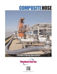
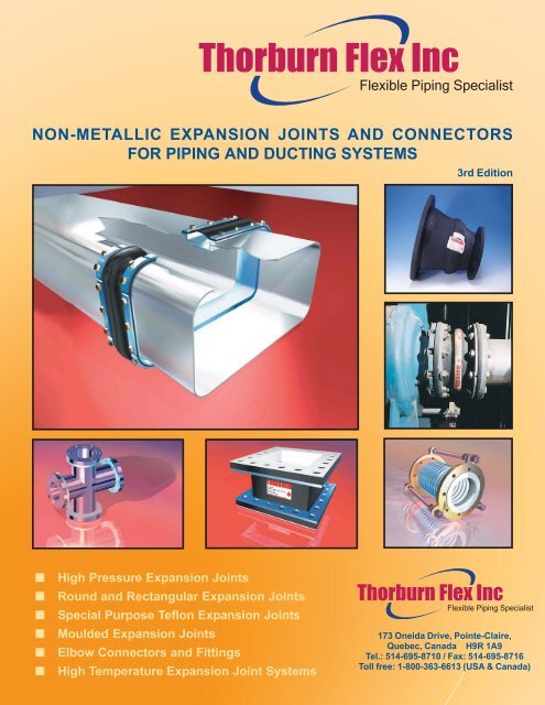
NON-METALLIC EXPANSION JOINTS AND CONNECTORS<br />
FOR PIPING AND DUCTING SYSTEMS<br />
■ High Pressure Expansion Joints<br />
■ Round and Rectangular Expansion Joints<br />
■ Special Purpose Teflon Expansion Joints<br />
■ Moulded Expansion Joints<br />
■ Elbow Connectors and Fittings<br />
■ High Temperature Expansion Joint Systems<br />
<strong>Thorburn</strong> <strong>Flex</strong> <strong>Inc</strong><br />
<strong>Flex</strong>ible Piping Specialist<br />
3rd Edition<br />
<strong>Thorburn</strong> <strong>Flex</strong> <strong>Inc</strong><br />
<strong>Flex</strong>ible Piping Specialist<br />
173 Oneida Drive, Pointe-Claire,<br />
Quebec, Canada H9R 1A9<br />
Tel.: 514-695-8710 / Fax: 514-695-8716<br />
Toll free: 1-800-363-6613 (USA & Canada)
<strong>Thorburn</strong> <strong>Flex</strong> <strong>Inc</strong><br />
<strong>Flex</strong>ible Piping Specialist<br />
THORBURN’S EMPLOYMENT OF<br />
STATE-OF-THE-ART TECHNOLOGY<br />
<strong>Thorburn</strong>’s committment to development is<br />
reinforced through the use of CAD (Computer<br />
Aided Design) system technology and finite<br />
engineering analysis, which permits <strong>Thorburn</strong><br />
to pinpoint potential critical areas and provide<br />
timely sound engineered solutions<br />
FOUNDER, Jack <strong>Thorburn</strong><br />
Shown is Jack <strong>Thorburn</strong>, who founded the<br />
company in 1954, enjoying one of his passions,<br />
sailing. Unfortunately, Jack passed away on<br />
February 16th 1995. He will be sorely missed.<br />
The company’s leadership passed on to Jack’s<br />
eldest son, Robert, in September 1994.<br />
<strong>Thorburn</strong> is an innovative manufacturer of specialized<br />
engineered flexible piping systems (i.e. custom hose<br />
assemblies and expansion joints). Since 1960, <strong>Thorburn</strong>’s<br />
corporate mission evolution and business philosophy<br />
have been customer driven and targeted to select niche<br />
applications where <strong>Thorburn</strong> can achieve clear positions<br />
of sustainable technological and market-share leadership.<br />
DESIGNING, BUILDING AND SUPPLYING<br />
THE WORLD’S FINEST<br />
EXPANSION JOINT AND CONNECTOR SYSTEMS
THORBURN THE FLEXIBLE PIPING SPECIALIST<br />
EXPERIENCE YOU CAN DEPEND ON<br />
Since 1960, <strong>Thorburn</strong> has devoted its expanding<br />
facilities and engineering expertise to the design,<br />
development and manufacture of flexible piping<br />
systems. Integrally associated with this product mix<br />
are <strong>Thorburn</strong>’s non-metallic expansion joints and<br />
connectors for piping and ducting systems.<br />
Specify <strong>Thorburn</strong> ducting and piping<br />
expansion joints and connectors and put your<br />
mind to rest.<br />
■ Emergency shut-down products at your service<br />
Tell us when you need the expansion joint or connector.<br />
Usually, we can supply sizes up to 36” in two days, 54” in<br />
three days and sizes up to 72” in four days.<br />
■ Compatible product line<br />
<strong>Thorburn</strong> has the most complete line of expansion joints<br />
and connectors in the industry. If we don’t have it, it’s not<br />
made. Call <strong>Thorburn</strong> for your single source of supply.<br />
■ Quality control<br />
<strong>Thorburn</strong> has a rigid certified quality control system to<br />
provide you with consistent quality products.<br />
■ Design integrity<br />
<strong>Thorburn</strong>’s non-metallic expansion joints are designed<br />
for tough, demanding industrial, commercial and<br />
municipal applications, such as: air conditioning, heating<br />
and ventilating systems, petrochemical, industrial process<br />
piping systems, power generating (fossil fuel and nuclear<br />
plants), marine, pulp and paper, waste water and sewage<br />
systems.<br />
Page 1<br />
QUALITY CONTROL<br />
■ CSA CAN3 Z299.1 certified<br />
■ ISO 9001<br />
■ Nuclear to ASME Section III NCA-4000<br />
Subsection NQA-1 CSA N285.0<br />
■ Welders and welding procedures ASME<br />
Section IX; VIII B31.1 and B31.3<br />
■ ASME B31.1, B31.3 Pressure piping<br />
certification<br />
■ Full traceability if required<br />
■ Size round up to 144” I.D.<br />
Rectangular, your design limits or our<br />
shipping door 14’ x 19’<br />
Test programs and design verification tests<br />
■ Expansion joint deflection test under design<br />
pressure<br />
■ Burst and hydrostatic testing to 150,000 psi<br />
■ Seismic and shock loading analysis<br />
■ External pressure testing for underwater<br />
service<br />
Our sincerest thanks to the many valued<br />
customers who have purchased <strong>Thorburn</strong>’s<br />
flexible piping products over the years. We look<br />
forward to working together with you and<br />
meriting your continued support for many years<br />
to come.<br />
Robert <strong>Thorburn</strong><br />
President
THORBURN THE FLEXIBLE PIPING SPECIALIST<br />
SUMMARY OF THORBURN'S NON-METALLIC<br />
FLEX CONNECTORS AND EXPANSION JOINTS<br />
MIGHTY-SPOOL HIGH PRESSURE PIPING EXPANSION JOINTS<br />
SPECIAL HAND BUILT LOW PRESSURE<br />
ROUND AND RECTANGULAR EXPANSION JOINTS<br />
Summary<br />
<strong>Thorburn</strong>'s custom designed low pressure round and rectangular elastomeric<br />
expansion joint systems.<br />
Arch profile: No arch to extra wide multiple arches.<br />
End connections: Integral moulded flat-face <strong>flanged</strong> drilled to<br />
your requirements or with labour saving cuff ends.<br />
Pressure/Temperature range:: Full vacuum to 25 psi / -60ºF<br />
to 400ºF.<br />
Size: Round up to 144"; Rectangular up to 19' x 14'.<br />
Specials: Can be made with concentric and eccentric, with special<br />
flanges, offsets or transition.<br />
SPECIAL PURPOSE TEFLON EXPANSION JOINTS<br />
Summary<br />
Summary<br />
<strong>Thorburn</strong>'s traditional work horse is the handcrafted elastomeric expansion joint system.<br />
It can be custom designed to suit specific application requirements. Available with any<br />
known elastomeric compound.<br />
Arch profile: High narrow arch design available with single, multiple or filled arches.<br />
End connections: Integral moulded flat-face drilled to your requirements or cuff ends<br />
with labour saving.<br />
Pressure/temperature range: Full vacuum to 300 psi / -60ºF to 400ºF<br />
Size I.D.: 1" to 144"<br />
Specials: Can be made with concentric, eccentric, special flanges, offsets, transition or<br />
from heavy duty externally pressurized designs.<br />
For extra high pressure external pressurized expansion joints, see page 67<br />
Teflon is the most versatile media resistant compound known to man<br />
and <strong>Thorburn</strong> offers the industry the broadest range of teflon expansion<br />
joints, either in moulded pure PTFE or teflon lined rubber or metal.<br />
Arch profile: Various to suit application.<br />
End connections: Flanged and drilled to your requirements.<br />
Pressure/Temperature range: Full vacuum to 300 psi / -60ºF to 400ºF.<br />
Size: 1/2" to 96" round.<br />
Page 2<br />
FOR DETAILS SEE PAGES 13 TO 20, 67<br />
FOR DETAILS SEE PAGES 22 TO 23<br />
FOR DETAILS SEE PAGES 54 TO 67
THORBURN THE FLEXIBLE PIPING SPECIALIST<br />
SUMMARY OF THORBURN'S NON-METALLIC<br />
FLEX CONNECTORS AND EXPANSION JOINTS<br />
MOULDED EXPANSION JOINTS FOR DETAILS SEE PAGES 34 TO 41<br />
Summary<br />
<strong>Thorburn</strong>'s moulded expansion joint series are economical joints and come in three basic<br />
styles: 1) Extra wide arch for double the movement per arch with full faced rubber flanges;<br />
2) Spherical self-cleaning arch system with floating flanges; 3) Small diameter spherical<br />
arch with threaded female ends. <strong>Thorburn</strong>'s moulded expansion joints are made from only<br />
limited amounts of elastomers.<br />
Arch profile: Long flowing self-cleaning style available in single or double moulded arches<br />
or multiple handbuilt versions.<br />
End connections: Flanged and female union style.<br />
Pressure/Temperature range: 26" Hg to 300 psi / -60ºF to 300ºF.<br />
Size I.D.: 1/2" to 36" round.<br />
Special: The moulded arch design can be made in a handbuilt version.<br />
ELBOW PUMP CONNECTORS AND FITTINGS FOR DETAILS SEE PAGES 42 TO 53<br />
Summary<br />
<strong>Thorburn</strong>'s rubber elbow connectors and fittings are designed to<br />
replace metallic or rubber lined products for pipe vibration, noise<br />
reduction or lateral movement. They are available in economical<br />
moulded as well as handbuilt versions. Available in any size of known<br />
elastomers.<br />
Arch profile: No arch, smooth tube.<br />
Pressure/Temperature range: Full vacuum to 300 psi / -60ºF to<br />
400ºF.<br />
Size: Round up to 30".<br />
Specials: <strong>Thorburn</strong>'s custom fittings can be made with transition<br />
joints, lateral, crosses or with custom radius elbows.<br />
DUCTING EXPANSION JOINT SYSTEMS FOR DETAILS SEE PAGES 68 TO 84<br />
Summary<br />
<strong>Thorburn</strong>'s <strong>Flex</strong>i-Duct Series FDR & FDC are non-metallic ducting expansion<br />
joints custom built and designed to provide stress relief in ducting systems<br />
by absorbing movement caused by thermal changes. They also act as vibration<br />
isolators, shock-absorbers and compensate for minor misalignment.<br />
Pressure: To ± 3 psi<br />
Temperature: Model FDR: below 400ºF; Model FDC: above 400ºF<br />
Special: Available in round or rectangular profiles<br />
Page 3
THORBURN THE FLEXIBLE PIPING SPECIALIST<br />
Introduction .................................................................... 6, 7<br />
Pipe simulation testing ...................................................... 8<br />
Applications<br />
<strong>Thorburn</strong> 42HP-HDX is specifically designed to provide<br />
under seawater piping relief with external or internal<br />
pressure differentials up to 225 psi. <strong>Thorburn</strong>’s 42HP-<br />
HDX technology was chosen for Canada’s largest<br />
offshore oil rig project: Hibernia<br />
Power generating industry ............................................. 9<br />
Marine / Commercial HVAC applications ..................... 10<br />
Waste water sewage treatment<br />
and drinking water treatment plant applications .......... 11<br />
Pulp and paper making process applications .............. 12<br />
Spool type expansion joints<br />
Introduction ............................................................ 13, 14<br />
Technical specifications: pressure,<br />
temperature, materials ................................................. 15<br />
Model 42HP: dimensional specifications ..................... 16<br />
Model 42HP movement/force/spring<br />
rate with single open arch design ................................ 17<br />
Models 42HP-CR (concentric) and 42HP-ER<br />
(eccentric) reducers specifications ........................ 18, 19<br />
Sleeve type Model 30DB ............................................. 20<br />
Low pressure round and rectangular expansion joints<br />
Models 15R (no arch) and 15RA (arch type) ............... 21<br />
Models 42HPO (offset type) and 42HPEF<br />
(enlarged flange type) .................................................. 21<br />
Models 15RR-LP (rectangular) and 15R-LP (round) ... 22<br />
Boot-<strong>Flex</strong> Model TCT ................................................... 23<br />
TABLE OF CONTENTS<br />
Page 4<br />
Technical data on flanges and control units<br />
Common flange dimension/drilling chart,<br />
mating pipe thickness for expansion joints,<br />
rubber pipe, retaining rings, control units ..................... 24<br />
Split retaining ring technology ...................................... 25<br />
Style CR Control rod assemblies - Introduction ........... 26<br />
Control rod assembly dimensions, ratings,<br />
how to order ................................................................. 27<br />
Installation and guiding practices<br />
Guiding, anchoring, installation, maintenance .... 28 to 31<br />
How to order custom rubber pipe expansion joints . 32, 33<br />
Moulded expansion joints<br />
TM20 Extra wide arch - Introduction ............................ 34<br />
TM20 Specifications .................................................... 35<br />
Introduction to Precision moulded Easy-<strong>Flex</strong> long<br />
flowing spherical arch expansion joint<br />
Series 101, 102 and 201 ........................................ 36, 37<br />
Easy-<strong>Flex</strong> Style 101 moulded single <strong>sphere</strong><br />
expansion joint system ................................................. 38<br />
Shown is a <strong>Thorburn</strong> 60” Mighty-Spool Model<br />
42HP multi-arch expansion joint system for the<br />
Ste-Marthe-du-Cap-de-la-Madeleine, Quebec,<br />
water treatment facility. This application’s<br />
requirements included absorbing ground settling<br />
movement and piping expansion.
THORBURN THE FLEXIBLE PIPING SPECIALIST<br />
Easy-<strong>Flex</strong> Style 201 moulded <strong>twin</strong> <strong>sphere</strong><br />
expansion joint system ................................................. 39<br />
Optional flange drilling ................................................. 40<br />
Easy-<strong>Flex</strong> Style 102 <strong>twin</strong>-<strong>sphere</strong> female<br />
metal threaded union rubber connectors ..................... 41<br />
Elbow-<strong>Flex</strong> expansion joints Series REF/REFR .... 42, 43<br />
Elbow connectors and fittings<br />
Flanged pump connector Model 60RPC ................ 44, 45<br />
Ultra-quiet coupled pipe connectors ............................ 46<br />
Paper mill suction couch Model 28TW ......................... 47<br />
<strong>Flex</strong>ipipe 60TMH and 61TMH - Introduction ................ 48<br />
<strong>Flex</strong>ipipe custom rubber hand crafted flexible pipes<br />
and fittings from 2” to 30” I.D. ....................................... 49<br />
<strong>Flex</strong>ipipe hose ends ..................................................... 50<br />
How to order flexipipe assemblies ............................... 51<br />
<strong>Thorburn</strong>’s special handcrafted rubber fittings ............. 52<br />
Fitting dimensions and ordering details ....................... 53<br />
Special purpose teflon expansion joints<br />
Model 42HP Spool type teflon lined exp. joints ...... 54, 55<br />
Easy-<strong>Flex</strong> Style 101 moulded teflon lined exp. joints ... 56<br />
Molded teflon expansion joints<br />
Power-<strong>Flex</strong> expansion joint system .............................. 57<br />
Power-<strong>Flex</strong> movement specifications ........................... 58<br />
How to calculate pressure temperature relationship<br />
for Power-<strong>Flex</strong> teflon expansion joint system ............... 59<br />
<strong>Thorburn</strong>’s lateral 60TMH-L custom rubber fitting system<br />
TABLE OF CONTENTS<br />
Page 5<br />
Shown is <strong>Thorburn</strong> self-cleaning, long flowing, single<br />
moulded spherical arch Series 101 expansion joint with<br />
floating flanges<br />
Power-<strong>Flex</strong> vacuum and dimensional data .................. 60<br />
Power-<strong>Flex</strong> typical styles and ordering information ...... 61<br />
Tef-<strong>Flex</strong> moulded PTFE expansion joints..................... 62<br />
Tef-<strong>Flex</strong> movement, weight and liner length data ......... 63<br />
Thor-Shield “safety shield” / Tef-<strong>Flex</strong> torque valves...... 64<br />
Hot-<strong>Flex</strong> “HF” teflon lined metal exp. joint system ........ 65<br />
Hot-<strong>Flex</strong> construction and ordering information ........... 66<br />
Special expansion joints<br />
Externally pressurized rubber expansion<br />
joint system .................................................................. 67<br />
Non-metallic ducting expansion joint systems<br />
<strong>Flex</strong>i-Duct Series FDR & FDC - Introduction ............... 68<br />
Why use non-metallic <strong>Flex</strong>i-Duct.................................. 69<br />
Applications ................................................................. 70<br />
Elastomeric and composite ducting - Introduction ....... 71<br />
<strong>Flex</strong>i-Duct engineering design concepts ................ 72, 73<br />
<strong>Flex</strong>i-Duct design considerations ........................... 74, 75<br />
Angle frame styles ................................................. 76, 77<br />
Moulded corner type “MC” ........................................... 78<br />
Materials, temperature limits, chemical compatibility ... 79<br />
How to order <strong>Flex</strong>i-Duct ......................................... 80, 81<br />
Installation instructions .......................................... 82, 83<br />
Data required ............................................................... 84<br />
Thermal expansion of pipe .......................................... 85<br />
Conversion Factors ................................................... 86, 87<br />
Warning, Warranty ........................................................... 88
THORBURN THE FLEXIBLE PIPING SPECIALIST<br />
THORBURN ELASTOMERIC PIPING EXPANSION<br />
JOINT AND CONNECTOR SYSTEM<br />
■ <strong>Flex</strong>ible piping system<br />
<strong>Thorburn</strong>’s elastomeric expansion joint<br />
and connector piping systems are<br />
sections of flexible pipe which are<br />
inserted into a rigid piping<br />
system. Regardless of materials<br />
and construction arrangements, <strong>Thorburn</strong>’s<br />
rubber piping expansion joints<br />
and connectors are designed to absorb<br />
various types of movements in a<br />
specified pressure/temperature range.<br />
■ Relieves piping stress<br />
The purpose of <strong>Thorburn</strong>’s rubber<br />
piping expansion joints is to relieve<br />
strain and stress in a piping system<br />
caused by thermal changes,<br />
misalignment, seismic activity,<br />
equipment vibration, load stresses,<br />
pump surges or ground settling.<br />
TYPICAL THORBURN 42HP<br />
SPOOL TYPE ARCH DESIGN<br />
CROSS<br />
SECTION<br />
Metal Wire<br />
Rubber<br />
Tube<br />
Carcass<br />
Fabric<br />
Reinforcing<br />
Cushion<br />
Rubber<br />
Rubber<br />
Cover<br />
Whether your piping problem is<br />
misalignment, noise or movement<br />
induced, let <strong>Thorburn</strong>’s<br />
expansion joint technology show<br />
you the way!<br />
■ Shape size range<br />
Round 1/2” to 144” I.D. Rectangular up to 20 feet; also<br />
available custom concentric, eccentric and transition ends<br />
custom built from various elastomers and fabrics. If you<br />
have any requirements, call <strong>Thorburn</strong> for a timely solution.<br />
■ End connections<br />
Flanged (metric/imperial), CUFF (Clamp-on style) or<br />
beaded for swivel <strong>flanged</strong> connections.<br />
■ Expansion joint arch types<br />
Custom handbuilt spool, double movement extra wide, long<br />
flowing spherical or no arch are custom designed by<br />
<strong>Thorburn</strong> to meet specific application requirements.<br />
THORBURN’S RUBBER EXPANSION JOINTS AND CONNECTORS<br />
QUALITY ASSURANCE CERTIFICATION AND COMPLIANCE<br />
■ ASME B31.1 and B31.3 pressure piping registration<br />
■ Rubber Manufacturers Association IP-2<br />
■ Fluid Sealing Association (FSA), Rubber Expansion Joint Division, Technical<br />
Handbook 5th and 6th Ed.<br />
■ CSA CAN3 Z299.1 QMI certified / N285.0 Class 6<br />
■ ISO 9001<br />
■ ASME Section III NCA-4000 Subsection NQA-1 (nuclear Class 1, 2, 3), N285.0<br />
■ Welders and Welding Procedures, ASME section IX, VIII B31.1 and B31.3<br />
THORBURN 60TMH<br />
AND 61TMH FLEXIBLE<br />
RUBBER PIPE<br />
CONNECTORS<br />
Page 6<br />
Helical wire reinforcement Tube<br />
Split retaining rings<br />
Fabric reinforcement<br />
<strong>Thorburn</strong> style 60TMH (wire reinforced), 61TMH (non wire<br />
reinforced) flexible rubber pipe connectors, Model 60RPC<br />
pump connectors and fittings are reinforced straight rubber<br />
pipes fabricated from various elastomers and fabrics primarily<br />
designed to absorb noise and vibration in a piping system.<br />
These custom connectors are also available as elbows, tees,<br />
laterals. In addition, <strong>Thorburn</strong> has the design and<br />
manufacturing capabilities to supply custom moulded branch<br />
and transition assemblies end. End connections’ types are the<br />
same as for rubber expansion joints.<br />
<strong>Thorburn</strong>’s rubber pipe connectors are detailed on pages 42 to 53
THORBURN THE FLEXIBLE PIPING SPECIALIST<br />
THORBURN RUBBER EXPANSION JOINT SYSTEM<br />
MEANS QUALITY PROTECTION EVERY TIME<br />
<strong>Thorburn</strong> rubber expansion joints are custom designed by engineers<br />
and fabricated by skilled craftsmen following rigid step-by-step<br />
quality control standards. <strong>Thorburn</strong>’s rubber expansion joints are used<br />
to address and solve defined pipe motion problems. If you have a<br />
specific requirement or want to reduce maintenance cost in your<br />
piping system, specify the right product the first time by calling<br />
<strong>Thorburn</strong>’s flexible piping specialist team today.<br />
Typical hand built <strong>Thorburn</strong><br />
rubber expansion joint<br />
Typical metallic bellows<br />
expansion joint<br />
<strong>Thorburn</strong>’s rubber pipe expansion joints absorb<br />
and isolate movement better. Here is why:<br />
■ High resistance to shock<br />
Unlike a metal joint, <strong>Thorburn</strong> rubber expansion joints absorb movements<br />
in all directions without stress and are capable of preventing unexpected<br />
shock induced movements caused by pumps, blowers and other agitating<br />
equipment, particularly during plant start-ups or shutdowns.<br />
Page 7<br />
<strong>Thorburn</strong>’s rubber expansion joint’s compact<br />
design simplifies installation<br />
THORBURN RUBBER EXPANSION<br />
JOINT’S DISTINCTIVE ADVANTAGES<br />
■ Compact to simplify installation<br />
■ Absorbs movement in all directions<br />
■ Reduces mechanical noises<br />
■ Compensates for misalignment<br />
■ Eliminates electrolysis between<br />
dissimilar metals<br />
■ Relieves strain in the piping system<br />
■ Doesn’t require gaskets<br />
■ Vibration and sound absorption<br />
<strong>Thorburn</strong>’s elastomeric joints offer significant advantages over a metallic joint, preventing transmission of vibration without harming<br />
the joint.<br />
■ Freedom from embrittlement<br />
Failure of a metal expansion joint is due primarily to continuous flexing and built-up stress points resulting in a fracture at the point<br />
of embrittlement . Constant/intermittent flexing keeps the rubber “alive” and eliminates flex cracking in <strong>Thorburn</strong>’s rubber expansion<br />
joints.<br />
■ Great recovery from movement<br />
When a metal joint is fully compressed, it assumes a permanent set. <strong>Thorburn</strong>’s rubber expansion joint continues to return to its<br />
original position.<br />
■ Freedom from corrosion<br />
To achieve comparable corrosion resistancy metal bellows would have to employ exotic alloys at a tremendous cost. In addition,<br />
<strong>Thorburn</strong>’s rubber expansion joints in sea water will not corrode nor does the continuous flexing permit scale to form.<br />
■ Superior abrasive and erosion resistance<br />
Thin metallic bellows will typically wear out at the root over time with minimum abrasion, where as a rubber joint can be manufactured<br />
with a smooth abrasion resistant lining to protect it from the harmful effects of sea water salt, slurry and other abrasive media.
THORBURN THE FLEXIBLE PIPING SPECIALIST<br />
FIRST IN RUBBER EXPANSION JOINT PIPE<br />
SIMULATION TESTING<br />
<strong>Thorburn</strong> is the only manufacturer capable of testing large diameter rubber expansion joints up to<br />
120” I.D. under actual design pressure or vacuum conditions, while simulating any design movement or<br />
series of movements experienced in a piping system during operation (i.e. design axial compression,<br />
extension and/or lateral deflection movements).<br />
Shown is <strong>Thorburn</strong>’s 42HP expansion joint subjected to a<br />
pressurized axial extension movement<br />
<strong>Inc</strong>reases quality and reduces costs<br />
<strong>Thorburn</strong>’s pipe simulator has dramatically increased the safety<br />
and quality standards of rubber expansion joints while reducing<br />
costly and dangerous failures from occurring during commissioning<br />
or during actual service.<br />
Shown is <strong>Thorburn</strong>’s 42HP spool type arch profile subjected to<br />
pressurized compression movement<br />
Page 8<br />
Exclusive <strong>Thorburn</strong> technology<br />
<strong>Thorburn</strong>’s pipe simulator allows rubber expansion joints to be<br />
subjected to actual field conditions before being put into service.<br />
Therefore, it provides the means to truly verify expansion joint<br />
performance and design capabilities as well as detect any defective<br />
or faulty expansion joints before commissioning them into service.<br />
Shown is an arch profile of <strong>Thorburn</strong>’s 42HP subjected to lateral<br />
movement under positive or negative pressure<br />
Typical applications for pipe simulator<br />
■ Superior verification testing<br />
Engineers and designers preferring to increase the quality of<br />
its piping system can specify <strong>Thorburn</strong> pipe simulation testing<br />
to verify the expansion joint design and performance<br />
capabilities before putting new expansion joints into service.<br />
■ Power generating industry preventive maintenance<br />
testing<br />
The quality standards required by both fossil fuel and nuclear<br />
electrical power generating industries can benefit by periodical<br />
pipe simulation testing of its existing expansion joints to verify<br />
the quality and uncover any potential weakness that could<br />
lead to a dangerous and costly failure.
THORBURN THE FLEXIBLE PIPING SPECIALIST<br />
POWER GENERATING INDUSTRY<br />
<strong>Thorburn</strong> has extensive successful experience in designing, manufacturing and supplying high pressure elastomeric expansion<br />
joints up to 108” (274 cm) I.D. to the world’s fossil fuel and nuclear power electrical generating stations.<br />
TYPICAL THORBURN RUBBER<br />
EXPANSION JOINT APPLICATIONS<br />
FOUND IN POWER GENERATING<br />
STATIONS<br />
■ Condenser circulating water<br />
system pump inlet and outlet<br />
■ Raw service water pump inlet and<br />
outlet<br />
■ Raw service water system heat<br />
exchanger inlet and outlet<br />
■ Raw service water strainer outlet<br />
■ Raw service water discharge line<br />
to the header<br />
REACTOR BUILDING<br />
Fuel<br />
Loading<br />
Machine Reactor<br />
Steam<br />
Typical <strong>Thorburn</strong> expansion joint<br />
being installed at electrical<br />
generator station<br />
TURBINE BUILDING<br />
Turbine<br />
<strong>Thorburn</strong>’s expansion joints were chosen for the AECL designed Candu Korean<br />
Wolsong 2, 3, 4 nuclear power generating stations<br />
<strong>Thorburn</strong>’s pipe simulator specialists pressure/vacuum testing<br />
<strong>Thorburn</strong> style 42HP rubber expansion joints under full design<br />
dynamic movement conditions<br />
Generator<br />
Circulating<br />
Water<br />
Page 9<br />
<strong>Thorburn</strong>’s packaging professionals<br />
meticulously preparing a 108” I.D.<br />
<strong>Thorburn</strong> 42HP joint for shipment<br />
Power industry expansion joints routing and location<br />
N.B. Power engineer inspecting a 24” I.D. <strong>Thorburn</strong> 42HP<br />
expansion joint at the Belledune generating station unit 2
THORBURN THE FLEXIBLE PIPING SPECIALIST<br />
MARINE APPLICATIONS<br />
<strong>Thorburn</strong> rubber expansion joints provide an economical solution in the isolation of noise transmission,<br />
vibration and connecting misaligned pipe found in offshore platforms and large marine vessels.<br />
<strong>Thorburn</strong> rubber expansion joints were chosen for<br />
Canada’s and one of the world’s largest off shore oil<br />
drilling platform. The Hibernia Project is situated in the<br />
Atlantic Ocean off the coast of Newfoundland, Canada.<br />
■ Air intake on diesel engines<br />
■ Ballast<br />
■ Between scoop and the condensers<br />
■ Circulating lines to the condenser<br />
■ Fog foam lines<br />
■ Schools ■ Stores ■ High rise office towers ■ Hotels<br />
<strong>Thorburn</strong> rubber expansion joints were<br />
chosen to provide stress and noise relief for<br />
the Canada Post headquarters building’s<br />
piping system in Ottawa, Ontario, Canada<br />
TYPICAL MARINE INSTALLATIONS<br />
■ Fire and bilge pump lines<br />
■ Forced draft lines<br />
■ Overboard discharge<br />
■ Sanitation system<br />
■ Ventilation lines<br />
Typical <strong>Thorburn</strong> rubber expansion joint<br />
location and routing<br />
■ Air ducts ■ Compressor lines ■ Circulating water lines ■ Pump suction and discharge ■ Turbine to condenser ■ Refrigeration<br />
Page 10<br />
<strong>Thorburn</strong>’s marine vessel rubber expansion joints routing and<br />
location<br />
OFFSHORE APPLICATIONS<br />
■ Mud pump-lines<br />
■ Diesel fuel lines<br />
■ Fresh water and sea water lines<br />
■ Permanent ballast water secondary<br />
containment piping system<br />
COMMERCIAL AND INSTITUTIONAL BUILDINGS<br />
AIR CONDITIONING, HEATING, VENTILATION SYSTEMS<br />
■ Apartment buildings<br />
■ Hospitals<br />
Typical commercial and institutional<br />
building installations for <strong>Thorburn</strong> rubber<br />
expansion joints
THORBURN THE FLEXIBLE PIPING SPECIALIST<br />
WASTE WATER SEWAGE TREATMENT<br />
DRINKING WATER TREATMENT PLANTS<br />
Consultants specify <strong>Thorburn</strong> rubber expansion joints<br />
and fittings to maximize design flexibility<br />
■ Aeration lines<br />
■ Raw sewage lines<br />
■ Grit pump lines<br />
Installing a typical rubber expansion<br />
joint in a waste water sewage<br />
treatment plant<br />
■ Sludge pumps<br />
■ Sinter sludge ash lines<br />
Page 11<br />
<strong>Thorburn</strong>’s rubber expansion joints were chosen for the multimillion<br />
dollar “Ville de Québec” water filtration project<br />
1 Aeration basin floating cover: connections are served with <strong>Thorburn</strong>’s 60TMH<br />
assemblies to provide the required flexibility to cover the changing level with<br />
variations in sewage flow.<br />
2 Air blowers: make extensive noise and the discharge is very hot. <strong>Thorburn</strong> high<br />
temperature (chlorobutyl) model TM20 joint can reduce noise by over 20 decibels.<br />
The air blower inlet side is connected with a <strong>Thorburn</strong> 30DB clamp-on type<br />
expansion joint to isolate vibration and pipe movement.<br />
3 Sludge pump lines are ideally suited for <strong>Thorburn</strong> long flowing arch style 202<br />
expansion joints. These expansion joints relieve stress from ground settlement or<br />
pipe and pump vibration misalignment.<br />
4 <strong>Thorburn</strong> 60TMH-E elbow fittings have proven even to outwear stainless steel<br />
elbows. Therefore, maintenance is greatly reduced for example on extremely<br />
abrasive slurry lines, such as sinter sludge ash.<br />
5 <strong>Thorburn</strong> 60TMH custom assemblies provide the required flexibility and design<br />
to dump sludge from plant to truck and loading docks or barge.<br />
Typical waste water treatment plant
THORBURN THE FLEXIBLE PIPING SPECIALIST<br />
■ Process piping systems<br />
■ Slurry lines<br />
■ Heating and cooling systems<br />
■ Pump inlet and discharge lines<br />
Saveall<br />
Beater<br />
PULP AND PAPER MAKING PROCESS<br />
Applications for <strong>Thorburn</strong> rubber expansion joints and<br />
custom connectors<br />
Wood source<br />
Power supply<br />
Refiner<br />
Schematic view of pulp & paper processing.<br />
■ Black liquor lines<br />
■ Suction box<br />
■ Causticizer and digester piping<br />
■ White water piping<br />
Pulpwood<br />
stacker Barking drum Water purification<br />
Washer Chipper Chip<br />
storage bin<br />
Bleached<br />
pulp<br />
storage<br />
Jordan<br />
Flow<br />
box<br />
Steam and<br />
power plant<br />
Mixing box<br />
Dandy<br />
roll<br />
FOURDRINIER<br />
Suction<br />
boxes Suction roll<br />
Pulp washers<br />
PRESSES<br />
Bleaching<br />
Bleaching<br />
Bleaching<br />
Screens<br />
Slice<br />
Felt<br />
blankets<br />
Case study: When Bowater<br />
Mersey Paper Co. had a<br />
problem with expansion joints<br />
located on their white water<br />
piping system, <strong>Thorburn</strong><br />
provided the solution with its<br />
42HP Series teflon lined<br />
rubber expansion joint system.<br />
Problem solved!<br />
Chip<br />
conveyors Digestor Blow<br />
tank Slaked<br />
lime<br />
storage<br />
Unbleached<br />
pulp<br />
storage<br />
DRYERS<br />
Page 12<br />
Brown<br />
stock<br />
Size press<br />
Cooking<br />
liquor<br />
Evaporator<br />
Black<br />
liquor<br />
Calender<br />
Green<br />
liquor<br />
storage<br />
Green<br />
liquor<br />
mixing tank<br />
Waste<br />
treatment plant<br />
Slaking<br />
tank<br />
Lime<br />
sludge<br />
CALENDERS<br />
Lime<br />
Kiln<br />
Slitter<br />
Filter<br />
Winder<br />
<strong>Thorburn</strong>’s flexible rubber piping and fitting technology was<br />
used to upgrade the traditional open trough piping found<br />
between the caustizer and slacker tank at Miramichi Pulp and<br />
Paper in New Castle, N.B.
THORBURN THE FLEXIBLE PIPING SPECIALIST<br />
MIGHTY-SPOOL<br />
HIGH QUALITY SPOOL JOINT SYSTEM<br />
35LP LOW PRESSURE 50SP MEDIUM PRESSURE 42HP HIGH PRESSURE 42HPX EXTRA HIGH PRESSURE<br />
Mighty-Spool Light-Weight<br />
Model 35LP and Multiple Arch<br />
Expansion Joint<br />
<strong>Thorburn</strong> Mighty-Spool single and<br />
multiple arch types are available in<br />
light-weight series Model 35LP. Dimensionally<br />
the same as the standard<br />
product, except for reduced body thickness,<br />
this series is designed for very<br />
low pressure and vacuum applications.<br />
Mighty-Spool multiple arch expansion<br />
joints are composites of the single arch<br />
design and are capable of movements<br />
of a single arch multiplied by the<br />
Mighty-Spool Hand Crafted Quality<br />
<strong>Thorburn</strong>’s Mighty-Spool expansion joints are the work horses of our rubber expansion<br />
joint line meeting or exceeding the design requirements listed in the FSA type A.1, A.2 and<br />
A.3 spool arch type joints. <strong>Thorburn</strong> does not employ marginal practices or materials,<br />
which reduce safety factors. All <strong>Thorburn</strong> Mighty-Spool joints meet a minimum 4 to 1<br />
safety factor at rated operating temperatures and pressures. <strong>Thorburn</strong>’s standard Model<br />
42HP High Pressure represents 65% of our sales.<br />
Fig. 1: Mighty-Spool single<br />
open arch design<br />
Mighty-Spool Filled Arch System<br />
<strong>Thorburn</strong> Mighty-Spool open arch design may be modified to reduce<br />
possible turbulence, prevent the collection of solids in the arch way, which<br />
could obstruct the joint movement. To solve such problems, <strong>Thorburn</strong>’s<br />
Mighty-Spool joints may be supplied with a bonded-in place soft filler rubber<br />
in the arch, providing a smooth interior bore. It should be noted that filled<br />
arches reduce movement capability to half (50%) and increase the spring rate<br />
by 4 times of the normal movements and spring rates of comparable size,<br />
Mighty-Spool open arch expansion joints. This general rule is similar for all<br />
<strong>Thorburn</strong> rubber expansion joints with filled arches.<br />
A<br />
Flange & Ret. Ring O.D.<br />
Nominal Pipe Size<br />
Joint I.D.<br />
B C<br />
F<br />
G<br />
E<br />
D<br />
To order Mighty-Spool expansion joints,<br />
please see pages 32 and 33 for details.<br />
Steel Retaining Ring<br />
Page 13<br />
<strong>Thorburn</strong> Mighty-Spool expansion joints are<br />
available in sizes from 1” to 144” I.D.<br />
Steel Retaining Ring<br />
Fig. 2: Mighty-Spool multiple open arch design<br />
number of arches. The spring rate for a multi-arch type expansion joint is equal to the spring rate for a single arch design divided by the<br />
number of arches. This general rule is similar for all <strong>Thorburn</strong> rubber expansion joints.<br />
In order to maintain lateral stability and prevent sagging when the joint is installed in a horizontal position, a maximum number of arches<br />
supplied is 4.<br />
Special note: <strong>Thorburn</strong> can provide special designs to accommodate movements of<br />
30” (600 mm). If greater movement or special ends are required in your piping system,<br />
call <strong>Thorburn</strong> flexible piping specialists today for an economical and timely solution.<br />
A<br />
A<br />
Equally Spaced<br />
Bolt Holes<br />
Hole<br />
Die<br />
Bolt Circle Bolt<br />
A<br />
Flange & Ret. Ring O.D.<br />
Nominal Pipe Size<br />
Joint I.D.<br />
B C<br />
Spool type expansion joint with filled and open arch<br />
design with a flange by sleeve type connecting end<br />
F<br />
Section AA<br />
G<br />
E<br />
D
THORBURN THE FLEXIBLE PIPING SPECIALIST<br />
<strong>Thorburn</strong>’s rubber expansion joint<br />
construction features<br />
Though <strong>Thorburn</strong> manufactures and supplies a wide<br />
variety of expansion joints, all our rubber joints have<br />
4 basic components: tube, reinforcement, cover and<br />
end connections. Shown to the right is <strong>Thorburn</strong> Mighty-<br />
Spool high pressure joint with integral flange.<br />
Tube:<br />
Seamless elastomeric leak proof lining specifically<br />
designed to maintain fluid leak tight integrity of the<br />
expansion joint and protect the carcass from penetration<br />
or saturation of the media being transferred. <strong>Thorburn</strong>’s<br />
expansion joint tubes can be designed to transfer chemical<br />
and petroleum products, sewage, gases as well as abrasive<br />
media.<br />
MIGHTY-SPOOL<br />
BUILT-IN QUALITY PIPE JOINTS<br />
<strong>Thorburn</strong> 108” Model<br />
42HP<br />
Cover placement<br />
during expansion joint<br />
rubber moulding and<br />
carcass building stages<br />
Typical Mighty-Spool cross-section expansion joint with integral flanges<br />
Page 14<br />
STYLE 42HP<br />
Integral flange<br />
Gap filler hard rubber<br />
Metallic<br />
reinforcement<br />
Protective cover<br />
High profile arch<br />
Reinforcement:<br />
a) Fabric Reinforcement: The fabric reinforcement is the flexible and supporting member between the tube and cover. Fabrics of<br />
high strength synthetic fibres are used depending on pressure and temperature requirements. All fabric plies are calendered to<br />
permit flexibility between the fabric plies and to reduce service strain.<br />
b) Metallic Reinforcement: Consists of coated high tensile spring steel wire and/or solid steel rings embedded in the carcass. The<br />
purpose of the metallic reinforcements is to strenghten the joint permitting the rated working pressures and to supply the joint with<br />
the necessary rigidity for thermal vacuum service. Specially compounded filler rubbers are used between the layers of metallic<br />
reinforcement to prevent migration when pressurized. Special metallic reinforcement is used when <strong>Thorburn</strong> rubber expansion<br />
joints are used for external service.<br />
Cover:<br />
The primary function of the cover is to protect the carcass from outside damage or abuse. Special elastomers can be supplied to resist<br />
chemicals, oils, sunlight, acid fumes, ozone, sea water, etc.<br />
End connections:<br />
Integral flanges are constructed of fabric reinforcement, smooth finish, full-faced flange that form a tight seal against the mating pipe<br />
flanges without the need of gaskets. Also available are soft cuff clamp-on ends designed to fit over a pipe and be clamped on.<br />
Inner liner<br />
Carcass<br />
<strong>Thorburn</strong> Mighty-Spool single open arch design being prepared for<br />
hydrostatic pressure testing
THORBURN THE FLEXIBLE PIPING SPECIALIST<br />
TECHNICAL SPECIFICATIONS<br />
THORBURN RUBBER PIPE EXPANSION JOINT AND PIPE CONNECTORS<br />
Nominal<br />
Design of Expansion Joint Construction<br />
Pipe Size Model 35LP Model 50SP Model 42HP Model 42HPX<br />
I.D. of Low Pressure Medium Pressure High Pressure Extra High<br />
Exp. Design Design Design Pressure Design<br />
Joint FSA Series A FSA Series B FSA Series C<br />
Positive Negative Positive Negative Positive Negative Positive Negative<br />
<strong>Inc</strong>hes PSIG in. of hg. PSIG in. of hg. PSIG in. of hg. PSIG in. of hg.<br />
1/4 to 4 165 26 165 30 200 30 300 30<br />
5 to 12 140 26 140 30 190 30 275 30<br />
14 85 15 65 30 130 30 225 30<br />
16 to 20 65 15 50 30 110 30 200 30<br />
22 to 24 65 15 45 30 100 30 175 30<br />
26 to 40 55 15 45 30 90 30 150 30<br />
42 to 66 55 15 40 30 80 30 150 30<br />
68 to 96 45 15 40 30 70 30 125 30<br />
98 to 108 40 15 40 30 60 30 90 30<br />
110 to 144 30 15 40 30 50 30 80 30<br />
Nominal<br />
Pipe Size<br />
I.D. of<br />
Exp.<br />
Joint<br />
Tolerances for <strong>Thorburn</strong> Rubber Pipe & Expansion Joints<br />
Non-<br />
Exp. critical<br />
joint flange Bolt<br />
Face to face length “F” 2 (inches)<br />
All dimensions to be an average reading.<br />
Applies to open or filled arch.<br />
I.D. 1 O.D. 1 line 3 0 to 6 7 to 12 14 to 18 20 & up<br />
0 to 10 ±3/16 ±1/4 ±3/16 ±1/8 +1/8 ±3/16 +3/16 4<br />
-3/16 -1/4<br />
12 to 22 ±1/4 ±3/8 ±1/4 ±1/8 +1/8 ±3/16 +3/16 4<br />
-3/16 -1/4<br />
24 to 46 ±3/8 ±1/2 ±5/16 +1/8 ±3/16 +3/16 ±1/4 4<br />
-3/16 -1/4<br />
48 to 70 +3/8 +3/4 ±3/8 ±3/16 +3/16 ±1/4 +1/4 5<br />
-1/2 -1/2 -1/4 -5/16<br />
72 & up +3/8 +1 ±1/2 +3/16 ±1/4 +1/4 +1/4 6<br />
-5/8 -3/4 -1/4 -5/16 -3/8<br />
1) All diameters to be measured with a “Pi” tape.<br />
2) All linear dimensions to be measured with a steel rule and averaged.<br />
3) Bolt line = Actual I.D. + 2 (Average “X” Dimension) + Bolt hole diameter<br />
Mechanical Vibration in a Steel Piping System Reduced with the<br />
Installation of <strong>Thorburn</strong>’s Pipe Connectors or Expansion Joints<br />
Pipe<br />
Installation in Pipe with a:<br />
System<br />
Vibration<br />
Frequency<br />
Expansion Joint<br />
8” ID x 6” F/F<br />
Vibration reduction at<br />
Rubber Pipe<br />
8” ID x 24” F/F<br />
Vibration reduction at<br />
HZ 10 PSIG 50 PSIG 80 PSIG 10 PSIG 50 PSIG 80 PSIG<br />
40 37% 55% 72% 87% 91% 93%<br />
68 60% 68% 78% 95% 96% 99%<br />
125 44% 50% 60% 98% 99% 99%<br />
250 44% 50% 50% 96% 97% 99%<br />
500 65% 89% 90% 91% 93% 94%<br />
1000 90% 96% 98% 82% 91% 96%<br />
2000 94% 95% 96% 99% 99% 99%<br />
4000 90% 93% 97% 99% 99% 99%<br />
8000 89% 89% 94% 97% 97% 98%<br />
Example: If an 8” steel piping system had a major vibration frequency of 1000 HZ at 50 PSIG,<br />
the installation of an expansion joint into the system, the percentage of reduction of vibration<br />
would be 96%.<br />
# of<br />
Measurements<br />
to<br />
be<br />
Averaged<br />
Page 15<br />
Pressure Characteristics of <strong>Thorburn</strong><br />
Mighty-Spool Expansion Joints<br />
Notes:<br />
1) Pressure limitations are based on a minimum 4 to 1 safety<br />
factor at 180ºF (82ºC) for rated pressure.<br />
2) For higher pressure and/or temperature expansion joint,<br />
contact <strong>Thorburn</strong> flexible piping specialists for details.<br />
3) Always advise <strong>Thorburn</strong> if expansion joint will be subjected<br />
to full vacuum.<br />
4) Model 42HP also available for external deep sea water<br />
service. Please specify <strong>Thorburn</strong> Model 42HPX-HD and<br />
provide all related service and design requirements.<br />
Type of elastomer Class Type of fabric Class<br />
Gum rubber Std. I Cotton Std. I<br />
Natural rubber Std. I Rayon Std. I<br />
SBR/GRS/Buna-S Std. I Nylon Std. II<br />
Neoprene Std. II Polyester Spc. II<br />
Buna-N/Nitrile Std. II Fiberglass/Asbestos Spc. II<br />
Hypalon Std. II Asbestos Spc. II<br />
Butyl Std. II Fiberglass Spc. II<br />
Butyl, Chloro Spc. II Kevlar Spc. II<br />
EPDM Spc. II Nomex Spc. II<br />
Viton/Fluorel Spc. II<br />
Silicone Spc. II<br />
Teflon/TFE/FEP Spc. II<br />
Maximum Service Temperature of Materials for<br />
<strong>Thorburn</strong>’s Expansion Joints and Pipe Connectors<br />
Stardard Class I - Recommended up to 180ºF<br />
Standard Class II - Recommended up to 230ºF<br />
Special Class II - Recommended for over 230ºF<br />
Rubber Acoustical Impedance Compared<br />
Sound Acoustical<br />
velocity Density impendance Relative<br />
Material (in./sec.) (lbs./in. 3 ) (lbs./in. 2 -sec.) Impendance<br />
Steel 206,500 0.283 58,400 500.0<br />
Copper 140,400 0.320 45,000 425.0<br />
Cast iron 148,800 0.260 38,700 365.0<br />
Lead 49,800 0.411 20,400 190.0<br />
Glass 216,000 0.094 20,300 190.0<br />
Concrete 198,000 0.072 14,200 134.0<br />
Water 56,400 0.036 2,030 19.0<br />
Pine 132,000 0.0145 1,910 18.0<br />
Cork 19200 0.0086 165 1.6<br />
Rubber 2,400 0.0442 106 1.0<br />
Acoustical impedance is defined as the product of material density times velocity of<br />
sound in that material. In acoustical systems low impedance corresponds to low sound<br />
transmission. Relative impedance is based on Rubber = 1.0
THORBURN THE FLEXIBLE PIPING SPECIALIST<br />
Nominal<br />
Pipe Size<br />
Exp. Jt. I.D.<br />
1<br />
1 1/4<br />
1 1/2<br />
2<br />
2 1/2<br />
3<br />
4<br />
5<br />
6<br />
8<br />
10<br />
12<br />
14<br />
16<br />
18<br />
20<br />
22<br />
24<br />
26<br />
28<br />
30<br />
32<br />
34<br />
36<br />
40<br />
42<br />
48<br />
50<br />
54<br />
56<br />
60<br />
66<br />
72<br />
78<br />
84<br />
96<br />
108<br />
144<br />
MIGHTY SPOOL MODEL 42HP<br />
QUALITY PROTECTING EXPANSION JOINTS<br />
Note: Flange and retaining ring dimensions shown are in accordance with 125/150 pound standard drilling of: ANSI B16.1, B16.24, B16.51, MSS SP-44. Items marked with * are drilled to AWWA<br />
C207-78 Table 1 Class D, Table 3, Class E. Retaining plate thickness “G” is 3/8” for all sizes.<br />
For larger diameters, offsize diameters, special drilling, special lengths, greater movements, reducers transition connectors or other specials, call<br />
<strong>Thorburn</strong>’s flexible piping team today at 1-800-363-6613.<br />
Expansion Joint<br />
Flange<br />
Single<br />
Arch<br />
6<br />
6<br />
6<br />
6<br />
6<br />
6<br />
6<br />
6<br />
6<br />
6<br />
8<br />
8<br />
8<br />
8<br />
8<br />
8<br />
10<br />
10<br />
10<br />
10<br />
10<br />
10<br />
10<br />
10<br />
10<br />
12<br />
12<br />
12<br />
12<br />
12<br />
12<br />
12<br />
12<br />
12<br />
12<br />
12<br />
12<br />
12<br />
For pressure temperature and other specifications, please see page 15<br />
“Face to Face” Minimum<br />
Recommended Length<br />
Two<br />
Arch<br />
10<br />
10<br />
10<br />
10<br />
10<br />
10<br />
10<br />
10<br />
10<br />
10<br />
12<br />
12<br />
12<br />
12<br />
12<br />
12<br />
14<br />
14<br />
14<br />
14<br />
14<br />
14<br />
14<br />
14<br />
14<br />
14<br />
14<br />
14<br />
14<br />
14<br />
14<br />
14<br />
14<br />
16<br />
16<br />
16<br />
16<br />
16<br />
Three<br />
Arch<br />
12<br />
12<br />
12<br />
12<br />
12<br />
12<br />
12<br />
12<br />
12<br />
14<br />
14<br />
14<br />
16<br />
16<br />
16<br />
16<br />
18<br />
18<br />
18<br />
18<br />
18<br />
18<br />
18<br />
18<br />
18<br />
18<br />
18<br />
18<br />
18<br />
18<br />
18<br />
18<br />
18<br />
18<br />
18<br />
18<br />
20<br />
20<br />
Typical 42HP<br />
Single open arch<br />
Four<br />
Arch<br />
14<br />
14<br />
14<br />
14<br />
14<br />
14<br />
14<br />
14<br />
16<br />
16<br />
16<br />
16<br />
20<br />
20<br />
20<br />
20<br />
22<br />
22<br />
22<br />
22<br />
22<br />
22<br />
22<br />
22<br />
22<br />
24<br />
24<br />
24<br />
24<br />
24<br />
24<br />
24<br />
24<br />
24<br />
24<br />
24<br />
24<br />
24<br />
Retaining<br />
Ring I.D.<br />
2 3/8<br />
2 5/8<br />
2 7/8<br />
3 5/8<br />
4 1/8<br />
4 5/8<br />
5 7/8<br />
6 7/8<br />
7 7/8<br />
9 7/8<br />
12 1/8<br />
14 1/2<br />
16 1/2<br />
18 1/2<br />
20 1/2<br />
22 5/8<br />
24 5/8<br />
26 5/8<br />
28 7/8<br />
30 7/8<br />
32 7/8<br />
34 7/8<br />
37<br />
39<br />
43<br />
45 1/4<br />
51 1/4<br />
53 1/4<br />
57 1/4<br />
59 1/4<br />
63 1/4<br />
69 1/4<br />
75 1/4<br />
81 1/4<br />
87 1/2<br />
99 3/8<br />
112 1/2<br />
149 1/2<br />
Standard Flange Dimensions<br />
and Drilling<br />
Flange<br />
O.D.<br />
4 1/4<br />
4 5/8<br />
5<br />
6<br />
7<br />
7 1/2<br />
9<br />
10<br />
11<br />
13 1/2<br />
16<br />
19<br />
21<br />
23 1/2<br />
25<br />
27 1/2<br />
29 1/2<br />
32<br />
34 1/4<br />
36 1/2<br />
38 3/4<br />
41 3/4<br />
43 3/4<br />
46<br />
50 3/4<br />
53<br />
59 1/2<br />
61 3/4<br />
66 1/4<br />
68 3/4<br />
73<br />
80<br />
86 1/2<br />
93<br />
99 3/4<br />
113 1/4<br />
126 3/4<br />
167 1/4<br />
Bolt<br />
Circle<br />
3 1/8<br />
3 1/2<br />
3 7/8<br />
4 3/4<br />
5 1/2<br />
6<br />
7 1/2<br />
8 1/2<br />
9 1/2<br />
11 3/4<br />
14 1/4<br />
17<br />
18 3/4<br />
21 1/4<br />
22 3/4<br />
25<br />
27 1/4<br />
29 1/2<br />
31 3/4<br />
34<br />
36<br />
38 1/2<br />
40 1/2<br />
42 3/4<br />
47 1/4<br />
49 1/2<br />
56<br />
58 1/4<br />
62 3/4<br />
65<br />
69 1/4<br />
76<br />
82 1/2<br />
89<br />
95 1/2<br />
108 1/2<br />
120 3/4<br />
158 1/4<br />
Page 16<br />
No. of<br />
Holes<br />
4<br />
4<br />
4<br />
4<br />
4<br />
4<br />
8<br />
8<br />
8<br />
8<br />
12<br />
12<br />
12<br />
16<br />
16<br />
20<br />
20<br />
20<br />
24<br />
28<br />
28<br />
28<br />
32<br />
32<br />
36<br />
36<br />
44<br />
44<br />
44<br />
48<br />
52<br />
52<br />
60<br />
64<br />
64<br />
68<br />
72<br />
84<br />
Diameter<br />
of Holes<br />
5/8<br />
5/8<br />
5/8<br />
3/4<br />
3/4<br />
3/4<br />
3/4<br />
7/8<br />
7/8<br />
7/8<br />
1<br />
1<br />
1 1/8<br />
1 1/8<br />
1 1/4<br />
1 1/4<br />
1 3/8<br />
1 3/8<br />
1 3/8<br />
1 3/8<br />
1 3/8<br />
1 5/8<br />
1 5/8<br />
1 5/8<br />
1 5/8<br />
1 5/8<br />
1 5/8<br />
1 7/8<br />
1 7/8<br />
1 7/8<br />
1 7/8<br />
1 7/8<br />
1 7/8<br />
2 1/8<br />
2 1/8<br />
2 3/8<br />
2 5/8<br />
3 3/8<br />
“A”<br />
9/16<br />
9/16<br />
9/16<br />
9/16<br />
9/16<br />
9/16<br />
9/16<br />
9/16<br />
5/8<br />
3/4<br />
3/4<br />
3/4<br />
7/8<br />
7/8<br />
7/8<br />
1<br />
1<br />
1<br />
1<br />
1<br />
1<br />
1<br />
1<br />
1<br />
1 3/16<br />
1 3/16<br />
1 3/16<br />
1 3/16<br />
1 3/16<br />
1 3/16<br />
1 3/16<br />
1 3/16<br />
1 3/16<br />
1 1/4<br />
1 1/4<br />
1 1/4<br />
1 1/4<br />
1 3/8<br />
FOR ORDERING DETAILS SEE PAGES 32 AND 33<br />
Retaining<br />
Ring<br />
Typical 42HP<br />
Single filled arch<br />
Typical Mighty-Spool<br />
Body Dimensions<br />
“B”<br />
1/2<br />
1/2<br />
5/8<br />
3/4<br />
7/8<br />
7/8<br />
7/8<br />
7/8<br />
7/8<br />
7/8<br />
1<br />
1 3/16<br />
1 3/16<br />
1 3/16<br />
1 3/16<br />
1 1/4<br />
1 1/4<br />
1 1/4<br />
1 3/8<br />
1 3/8<br />
1 3/8<br />
1 3/8<br />
1 3/8<br />
1 3/8<br />
1 3/8<br />
1 1/2<br />
1 1/2<br />
1 1/2<br />
1 1/2<br />
1 1/2<br />
1 1/2<br />
1 1/2<br />
1 1/2<br />
1 5/8<br />
1 5/8<br />
1 5/8<br />
1 5/8<br />
1 3/4<br />
Typical 42HP<br />
Two open arches<br />
“C”<br />
1 1/8<br />
1 1/8<br />
1 1/8<br />
1 1/4<br />
1 1/4<br />
1 1/4<br />
1 1/4<br />
1 1/4<br />
1 1/4<br />
1 1/2<br />
1 1/2<br />
1 1/2<br />
2<br />
2<br />
2<br />
2<br />
2<br />
2<br />
2 1/4<br />
2 1/4<br />
2 1/4<br />
2 1/4<br />
2 1/4<br />
2 1/4<br />
2 1/4<br />
2 1/2<br />
2 1/2<br />
2 1/2<br />
2 1/2<br />
2 1/2<br />
2 1/2<br />
2 1/2<br />
2 1/2<br />
2 1/2<br />
2 1/2<br />
2 1/2<br />
2 1/2<br />
2 1/2<br />
“D”<br />
1/2<br />
1/2<br />
1/2<br />
1/2<br />
1/2<br />
1/2<br />
1/2<br />
1/2<br />
1/2<br />
3/4<br />
3/4<br />
3/4<br />
3/4<br />
3/4<br />
3/4<br />
7/8<br />
7/8<br />
7/8<br />
1<br />
1<br />
1<br />
1<br />
1<br />
1<br />
1<br />
1 1/8<br />
1 1/8<br />
1 1/8<br />
1 1/8<br />
1 1/8<br />
1 1/8<br />
1 1/8<br />
1 1/8<br />
1 1/8<br />
1 1/8<br />
1 1/8<br />
1 1/8<br />
1 1/8<br />
“E”<br />
7/16<br />
7/16<br />
7/16<br />
1/2<br />
1/2<br />
1/2<br />
1/2<br />
1/2<br />
1/2<br />
5/8<br />
11/16<br />
11/16<br />
3/4<br />
3/4<br />
3/4<br />
25/32<br />
25/32<br />
25/32<br />
1 3/16<br />
1 3/16<br />
1 3/16<br />
1 3/16<br />
1 3/16<br />
1 3/16<br />
1 3/16<br />
29/32<br />
29/32<br />
29/32<br />
29/32<br />
29/32<br />
29/32<br />
29/32<br />
29/32<br />
1<br />
1<br />
1<br />
1<br />
1 1/8<br />
Typical 42HP<br />
Three open arches
THORBURN THE FLEXIBLE PIPING SPECIALIST<br />
MIGHTY-SPOOL MODEL 42HP<br />
MOVEMENT/FORCE/SPRING RATE WITH SINGLE OPEN ARCH DESIGN<br />
Nominal<br />
Pipe Size<br />
Exp. Jt. I.D.<br />
1<br />
1 1/4<br />
1 1/2<br />
2<br />
2 1/2<br />
3<br />
4<br />
5<br />
6<br />
8<br />
10<br />
12<br />
14<br />
16<br />
18<br />
20<br />
22<br />
24<br />
26<br />
28<br />
30<br />
32<br />
34<br />
36<br />
40<br />
42<br />
48<br />
50<br />
54<br />
56<br />
60<br />
66<br />
72<br />
78<br />
84<br />
96<br />
108<br />
144<br />
“Face to face”<br />
minimum length<br />
<strong>Inc</strong>hes of axial<br />
compression<br />
Non-Concurrent<br />
Movement Capability<br />
<strong>Inc</strong>hes of axial<br />
extension<br />
<strong>Inc</strong>hes of lateral<br />
deflection<br />
Degrees of<br />
angular<br />
movement<br />
Total load lbs<br />
for rated<br />
compression<br />
Page 17<br />
Force Pounds<br />
Total load lbs<br />
for rated<br />
extension<br />
Total load lbs<br />
for rated<br />
lateral defl.<br />
Total load foot<br />
lbs for rated<br />
angular move.<br />
Force pounds<br />
for 1” compression<br />
mov.<br />
Spring Rate<br />
Force pounds<br />
for 1” extension<br />
mov.<br />
Force pounds<br />
for 1” lateral<br />
deflection<br />
Est. Wt (lbs)<br />
Special notes on movement capability: 1) Filled arch construction reduces above movements by 50%. 2) To calculate movement of multiple arch type for compression extension and lateral<br />
movements, take movement shown in the above table and multiply by the number of arches. 3) The degree of angular movement is based on the maximum extension shown. 4) Movement capability<br />
shown is non-concurrent percentage used in one movement position must be deducted from the other movement position so that sum of movements don’t exceed 100%. 5) Movements shown are<br />
based on proper installation practices. See <strong>Thorburn</strong> installation maintenance guide for details.<br />
Special notes on force Pounds / Spring Rates: 1) Forces required to move <strong>Thorburn</strong> Mighty-Spool Model 42HP are based on zero pressure conditions and room temperature in the pipeline. 2)<br />
These forces should be considered only as approximates, compensation must be made for more accurate forces based on materials of construction and actual service conditions. 3) Filled arch spring<br />
rates are approximately 4 times that of a single open arch. 4) Multi-arch spring rates are equal to single arch divided by number of arches.<br />
Axial<br />
Compression<br />
6<br />
6<br />
6<br />
6<br />
6<br />
6<br />
6<br />
6<br />
6<br />
6<br />
8<br />
8<br />
8<br />
8<br />
8<br />
8<br />
10<br />
10<br />
10<br />
10<br />
10<br />
10<br />
10<br />
10<br />
10<br />
12<br />
12<br />
12<br />
12<br />
12<br />
12<br />
12<br />
12<br />
12<br />
12<br />
12<br />
12<br />
12<br />
For pressure temperature and other specifications, please see page 15<br />
7/16<br />
7/16<br />
7/16<br />
7/16<br />
7/16<br />
7/16<br />
7/16<br />
7/16<br />
7/16<br />
11/16<br />
11/16<br />
11/16<br />
11/16<br />
11/16<br />
13/16<br />
13/16<br />
13/16<br />
15/16<br />
15/16<br />
15/16<br />
15/16<br />
15/16<br />
15/16<br />
15/16<br />
1 1/16<br />
1 1/16<br />
1 1/16<br />
1 1/16<br />
1 1/16<br />
1 1/16<br />
1 1/16<br />
1 1/16<br />
1 1/16<br />
1 1/16<br />
1 1/16<br />
1 1/16<br />
1 1/16<br />
1 1/16<br />
1/4<br />
1/4<br />
1/4<br />
1/4<br />
1/4<br />
1/4<br />
1/4<br />
1/4<br />
1/4<br />
3/8<br />
3/8<br />
3/8<br />
3/8<br />
3/8<br />
7/16<br />
7/16<br />
7/16<br />
1/2<br />
1/2<br />
1/2<br />
1/2<br />
1/2<br />
1/2<br />
1/2<br />
9/16<br />
9/16<br />
9/16<br />
9/16<br />
9/16<br />
9/16<br />
9/16<br />
9/16<br />
9/16<br />
9/16<br />
9/16<br />
9/16<br />
9/16<br />
9/16<br />
Axial<br />
Elongation<br />
1/2<br />
1/2<br />
1/2<br />
1/2<br />
1/2<br />
1/2<br />
1/2<br />
1/2<br />
1/2<br />
1/2<br />
1/2<br />
1/2<br />
1/2<br />
1/2<br />
1/2<br />
1/2<br />
1/2<br />
1/2<br />
1/2<br />
1/2<br />
1/2<br />
1/2<br />
1/2<br />
1/2<br />
1/2<br />
1/2<br />
1/2<br />
1/2<br />
1/2<br />
1/2<br />
1/2<br />
1/2<br />
1/2<br />
1/2<br />
1/2<br />
1/2<br />
1/2<br />
1/2<br />
27.5<br />
22.5<br />
18.5<br />
14.5<br />
11.5<br />
10.0<br />
7.5<br />
6.0<br />
5.0<br />
5.5<br />
4.5<br />
3.75<br />
3.25<br />
2.75<br />
2.5<br />
2.5<br />
2.25<br />
2.0<br />
2.3<br />
2.0<br />
2.0<br />
1.8<br />
1.75<br />
1.5<br />
1.5<br />
1.5<br />
1.25<br />
1.25<br />
1.25<br />
1.25<br />
1.0<br />
1.0<br />
0.9<br />
0.9<br />
0.8<br />
0.7<br />
0.62<br />
0.47<br />
103<br />
129<br />
154<br />
185<br />
232<br />
278<br />
371<br />
463<br />
556<br />
971<br />
1214<br />
1456<br />
1274<br />
1456<br />
1638<br />
2152<br />
2367<br />
2582<br />
2869<br />
3090<br />
3311<br />
3531<br />
3752<br />
3973<br />
4414<br />
4732<br />
5408<br />
5634<br />
6085<br />
6310<br />
6761<br />
7437<br />
8113<br />
8789<br />
9465<br />
10817<br />
12169<br />
16218<br />
Typical <strong>Thorburn</strong> Rubber Expansion Joints<br />
Angular Movement<br />
Bending of the centerline<br />
76<br />
96<br />
115<br />
138<br />
172<br />
207<br />
276<br />
344<br />
413<br />
689<br />
861<br />
1033<br />
904<br />
1033<br />
1163<br />
1505<br />
1656<br />
1807<br />
1990<br />
2143<br />
2297<br />
2450<br />
2603<br />
2756<br />
3062<br />
3253<br />
3717<br />
3872<br />
4182<br />
4341<br />
4651<br />
5116<br />
5581<br />
6046<br />
6511<br />
7441<br />
8372<br />
11152<br />
175<br />
219<br />
262<br />
350<br />
381<br />
412<br />
476<br />
546<br />
617<br />
753<br />
809<br />
948<br />
1117<br />
1286<br />
1420<br />
1588<br />
1648<br />
1706<br />
1829<br />
1952<br />
2075<br />
2438<br />
2801<br />
3164<br />
3338<br />
3423<br />
3866<br />
4012<br />
4303<br />
4448<br />
4736<br />
5108<br />
5477<br />
5951<br />
6425<br />
7375<br />
8325<br />
11013<br />
1<br />
2<br />
3<br />
4<br />
6<br />
8<br />
14<br />
22<br />
32<br />
70<br />
109<br />
158<br />
160<br />
209<br />
266<br />
381<br />
463<br />
549<br />
659<br />
765<br />
875<br />
1000<br />
1130<br />
1266<br />
1563<br />
1745<br />
2282<br />
2460<br />
2885<br />
3081<br />
3537<br />
4288<br />
5113<br />
6022<br />
6913<br />
9409<br />
13550<br />
20164<br />
Torsional Movement<br />
Relation about the<br />
centerline (twist)<br />
235<br />
294<br />
353<br />
423<br />
530<br />
635<br />
848<br />
1058<br />
1271<br />
1412<br />
1766<br />
2118<br />
1853<br />
2118<br />
2382<br />
2649<br />
2913<br />
3178<br />
3060<br />
3296<br />
3532<br />
3769<br />
4002<br />
4238<br />
4708<br />
4452<br />
5087<br />
5300<br />
5724<br />
5936<br />
6360<br />
6996<br />
7632<br />
8268<br />
8904<br />
10176<br />
11448<br />
15264<br />
FOR ORDERING DETAILS SEE PAGES 32 AND 33<br />
304<br />
383<br />
459<br />
552<br />
689<br />
828<br />
1104<br />
1376<br />
1652<br />
1837<br />
2296<br />
2755<br />
2411<br />
2755<br />
3101<br />
3440<br />
3785<br />
4130<br />
3980<br />
4286<br />
4594<br />
4899<br />
5602<br />
5512<br />
6124<br />
5783<br />
6608<br />
6884<br />
7435<br />
7717<br />
8268<br />
9095<br />
9922<br />
10748<br />
11575<br />
13228<br />
14883<br />
19843<br />
350<br />
438<br />
524<br />
700<br />
762<br />
824<br />
952<br />
1092<br />
1234<br />
1506<br />
1618<br />
1896<br />
2234<br />
2572<br />
2840<br />
3176<br />
3296<br />
3412<br />
3658<br />
3904<br />
4150<br />
4876<br />
5602<br />
6328<br />
6676<br />
6846<br />
7732<br />
8024<br />
8606<br />
8896<br />
9472<br />
10216<br />
10954<br />
11902<br />
12850<br />
14750<br />
16650<br />
22026<br />
Lateral Movement<br />
Shear or perpendicular<br />
to centerline<br />
Joint<br />
single arch<br />
2<br />
2.5<br />
3<br />
4<br />
4.5<br />
5.5<br />
8<br />
9<br />
11<br />
15<br />
23<br />
34<br />
40<br />
47<br />
56<br />
67<br />
70<br />
79<br />
100<br />
102<br />
117<br />
127<br />
138<br />
143<br />
173<br />
193<br />
198<br />
211<br />
265<br />
288<br />
309<br />
350<br />
385<br />
410<br />
435<br />
485<br />
650<br />
850<br />
Retaining<br />
ring set<br />
2.3<br />
2.5<br />
3<br />
4<br />
5.5<br />
6<br />
7.5<br />
8<br />
9<br />
12<br />
18<br />
22<br />
25<br />
27<br />
29<br />
35<br />
44<br />
48<br />
53<br />
58<br />
66<br />
75<br />
88<br />
91<br />
106<br />
116<br />
138<br />
154<br />
163<br />
184<br />
200<br />
246<br />
300<br />
325<br />
350<br />
432<br />
540<br />
700<br />
Absorbing<br />
Vibration
THORBURN THE FLEXIBLE PIPING SPECIALIST<br />
MIGHTY-SPOOL<br />
MODELS 42HP-CR AND 42HP-ER CONCENTRIC AND<br />
ECCENTRIC REDUCER EXPANSION JOINTS<br />
<strong>Thorburn</strong>’s Mighty-Spool concentric and eccentric reducers were specifically developed to connect<br />
piping of unequalled diameters. These reducers were designed to replace and address the limitations<br />
found in metal reducers in a pipeline.<br />
Compare the Mighty-Spool advantages<br />
over metallic reducers:<br />
■ Absorbs pipe-wall and fluid-born noise<br />
<strong>Thorburn</strong>’s reducers are quiet operating and<br />
are designed to replace sound transmitting<br />
metal reducers. Pipe-wall sound loses energy<br />
and is absorbed as the noise carried by the<br />
piping both enters and leaves the rubber section.<br />
Fluid-born noise is absorbed by volumetric<br />
expansion (breathing) of <strong>Thorburn</strong>’s Mighty-<br />
Spool reducer. This action cushions water<br />
hammer and smooths out pumping impulses.<br />
■ Reduces system stress and strain /<br />
Compensates for misalignment<br />
Rigid attachment of piping to critical or<br />
mechanical equipment can produce excessive<br />
loading. Thermal or mechanically created<br />
strain-stress-shock are cushioned and absorbed<br />
with <strong>Thorburn</strong>’s Mighty-Spool reducers.<br />
<strong>Thorburn</strong>’s reducers add a flexible component<br />
that is automatically self correcting for<br />
misalignment created by structural movements<br />
caused by settling, expansion or ground shifts.<br />
■ Less space, lower installation cost<br />
<strong>Thorburn</strong>’s Mighty-Spool reducers replace a<br />
metal reducer and a flexible element. Thus,<br />
less space is required and installation is<br />
simplified.<br />
Page 18<br />
<strong>Thorburn</strong> 42HP-CR Concentric<br />
reducer expansion joint<br />
Control Rod Bolt Circle<br />
Control Rod Bolt Circle<br />
Flange/Retaining Ring O.D.<br />
Flange/Retaining Ring O.D.<br />
Bolt Circle<br />
Control<br />
Rod<br />
Plate Retaining<br />
Ring<br />
Optional<br />
Compression Sleeve<br />
Steel<br />
Washer<br />
<strong>Thorburn</strong> 42HP-ER Eccentric<br />
reducer expansion joint<br />
Standard<br />
Pipe<br />
Flange<br />
Nominal<br />
Pipe Size<br />
Joint I.D.<br />
<strong>Thorburn</strong> Model 42HP-CR concentric reducer rubber expansion<br />
joint<br />
Bolt Circle<br />
Control<br />
Rod<br />
Plate Retaining<br />
Ring<br />
Optional<br />
Compression Sleeve<br />
Steel<br />
Washer<br />
Standard<br />
Pipe<br />
Flange<br />
Nominal<br />
Pipe Size<br />
Joint I.D.<br />
<strong>Thorburn</strong> Model 42HP-ER eccentric reducer rubber expansion joint
THORBURN THE FLEXIBLE PIPING SPECIALIST<br />
42HP-CR<br />
42HP-ER<br />
Typical<br />
Joint size<br />
I.D.1 x I.D.2<br />
x length<br />
2 x 1 x 6<br />
2 x 1.5 x 6<br />
2.5 x 1.5 x 6<br />
2.5 x 2 x 6<br />
3 x 1.5 x 6<br />
3 x 2 x 6<br />
3 x 2.5 x 6<br />
4 x 2 x 6<br />
4 x 2 x 7<br />
4 x 2.5 x 6<br />
4 x 2.5 x 7<br />
4 x 3 x 6<br />
4 x 3 x 7<br />
5 x 3 x 6<br />
5 x 4 x 6<br />
5 x 4 x 8<br />
6 x 2 x 8<br />
6 x 2.5 x 6<br />
6 x 3 x 6<br />
6 x 3 x 9<br />
6 x 4 x 6<br />
6 x 4 x 8<br />
6 x 4 x 9<br />
6 x 5 x 6<br />
6 x 5 x 9<br />
8 x 3 x 6<br />
8 x 4 x 6<br />
8 x 4 x 8<br />
8 x 4 x 11<br />
8 x 5 x 6<br />
8 x 5 x 11<br />
8 x 6 x 6<br />
8 x 6 x 8<br />
8 x 6 x 11<br />
10 x 5 x 8<br />
10 x 6 x 8<br />
10 x 6 x 12<br />
10 x 8 x 6<br />
10 x 8 x 8<br />
10 x 8 x 12<br />
12 x 6 x 8<br />
12 x 6 x 14<br />
12 x 8 x 6<br />
12 x 8 x 8<br />
12 x 8 x 14<br />
12 x 10 x 8<br />
12 x 10 x 14<br />
14 x 8 x 8<br />
14 x 10 x 8<br />
14 x 12 x 8<br />
16 x 10 x 8<br />
16 x 12 x 8<br />
16 x 14 x 8<br />
18 x 12 x 8<br />
18 x 14 x 8<br />
18 x 16 x 8<br />
MIGHTY-SPOOL EXPANSION JOINTS<br />
MODEL 42HP-CR CONCENTRIC AND<br />
MODEL 42HP-ER ECCENTRIC REDUCERS SPECIFICATIONS<br />
Total travel<br />
compress –<br />
Extend<br />
(inches)<br />
5.5 - 6.25<br />
5.5 - 6.25<br />
5.5 - 6.25<br />
5.5 - 6.25<br />
5.5 - 6.25<br />
5.5 - 6.25<br />
5.5 - 6.25<br />
5.5 - 6.25<br />
6.5 - 7.25<br />
5.5 - 6.25<br />
6.5 - 7.25<br />
5.5 - 6.25<br />
6.5 - 7.25<br />
5.5 - 6.25<br />
5.5 - 6.25<br />
7.5 - 8.25<br />
7.5 - 8.25<br />
5.5 - 6.25<br />
5.5 - 6.25<br />
8.5 - 9.25<br />
5.5 - 6.25<br />
7.5 - 8.25<br />
8.5 - 9.25<br />
5.5 - 6.25<br />
8.5 - 9.25<br />
5.25 - 6.375<br />
5.25 - 6.375<br />
7.25 - 8.375<br />
10.25 - 11.375<br />
5.25 - 6.375<br />
10.25 - 11.375<br />
5.25 - 6.375<br />
7.25 - 8.375<br />
10.25 - 11.375<br />
7.25 - 8.375<br />
7.25 - 8.375<br />
11.25 - 12.375<br />
5.25 - 6.375<br />
7.25 - 8.375<br />
11.25 - 12.375<br />
7.25 - 8.375<br />
13.25 - 14.375<br />
5.25 - 6.375<br />
7.25 - 8.375<br />
13.25 - 14.375<br />
7.25 - 8.375<br />
13.25 - 14.375<br />
7.25 - 8.375<br />
7.25 - 8.375<br />
7.25 - 8.375<br />
7.25 - 8.375<br />
7.25 - 8.375<br />
7.25 - 8.375<br />
7.25 - 8.375<br />
7.25 - 8.375<br />
7.25 - 8.375<br />
Movement Capability<br />
Axial<br />
compress<br />
(inches)<br />
Axial<br />
extend<br />
(inches)<br />
.5<br />
.5<br />
.5<br />
.5<br />
.5<br />
.5<br />
.5<br />
.5<br />
.5<br />
.5<br />
.5<br />
.5<br />
.5<br />
.5<br />
.5<br />
.5<br />
.5<br />
.5<br />
.5<br />
.5<br />
.5<br />
.5<br />
.5<br />
.5<br />
.5<br />
.75<br />
.75<br />
.75<br />
.75<br />
.75<br />
.75<br />
.75<br />
.75<br />
.75<br />
.75<br />
.75<br />
.75<br />
.75<br />
.75<br />
.75<br />
.75<br />
.75<br />
.75<br />
.75<br />
.75<br />
.75<br />
.75<br />
.75<br />
.75<br />
.75<br />
.75<br />
.75<br />
.75<br />
.75<br />
.75<br />
.75<br />
.25<br />
.25<br />
.25<br />
.25<br />
.25<br />
.25<br />
.25<br />
.25<br />
.25<br />
.25<br />
.25<br />
.25<br />
.25<br />
.25<br />
.25<br />
.25<br />
.25<br />
.25<br />
.25<br />
.25<br />
.25<br />
.25<br />
.25<br />
.25<br />
.25<br />
.375<br />
.375<br />
.375<br />
.375<br />
.375<br />
.375<br />
.375<br />
.375<br />
.375<br />
.375<br />
.375<br />
.375<br />
.375<br />
.375<br />
.375<br />
.375<br />
.375<br />
.375<br />
.375<br />
.375<br />
.375<br />
.375<br />
.375<br />
.375<br />
.375<br />
.375<br />
.375<br />
.375<br />
.375<br />
.375<br />
.375<br />
Lateral<br />
deflect<br />
(inches)<br />
.5<br />
.5<br />
.5<br />
.5<br />
.5<br />
.5<br />
.5<br />
.5<br />
.5<br />
.5<br />
.5<br />
.5<br />
.5<br />
.5<br />
.5<br />
.5<br />
.5<br />
.5<br />
.5<br />
.5<br />
.5<br />
.5<br />
.5<br />
.5<br />
.5<br />
.5<br />
.5<br />
.5<br />
.5<br />
.5<br />
.5<br />
.5<br />
.5<br />
.5<br />
.5<br />
.5<br />
.5<br />
.5<br />
.5<br />
.5<br />
.5<br />
.5<br />
.5<br />
.5<br />
.5<br />
.5<br />
.5<br />
.5<br />
.5<br />
.5<br />
.5<br />
.5<br />
.5<br />
.5<br />
.5<br />
.5<br />
Angular<br />
deflect<br />
(degree)<br />
18.4<br />
15.9<br />
14.1<br />
12.5<br />
12.5<br />
11.3<br />
10.3<br />
9.5<br />
9.5<br />
8.8<br />
8.8<br />
8.2<br />
8.2<br />
7.1<br />
6.4<br />
6.4<br />
7.1<br />
6.7<br />
6.4<br />
6.4<br />
5.7<br />
5.7<br />
5.7<br />
5.2<br />
5.2<br />
7.8<br />
7.1<br />
7.1<br />
7.1<br />
6.6<br />
6.6<br />
6.1<br />
6.1<br />
6.1<br />
5.7<br />
5.3<br />
5.3<br />
4.8<br />
4.8<br />
4.8<br />
4.8<br />
4.8<br />
4.3<br />
4.3<br />
4.3<br />
3.9<br />
3.9<br />
3.9<br />
3.6<br />
3.3<br />
3.3<br />
3.1<br />
2.9<br />
2.9<br />
2.7<br />
2.6<br />
Page 19<br />
Degrees<br />
torsion<br />
3<br />
3<br />
3<br />
3<br />
3<br />
3<br />
3<br />
3<br />
3<br />
3<br />
3<br />
3<br />
3<br />
3<br />
3<br />
3<br />
3<br />
3<br />
3<br />
3<br />
3<br />
3<br />
3<br />
3<br />
3<br />
3<br />
3<br />
3<br />
3<br />
3<br />
3<br />
3<br />
3<br />
3<br />
3<br />
3<br />
3<br />
3<br />
3<br />
3<br />
3<br />
3<br />
3<br />
3<br />
3<br />
3<br />
3<br />
2<br />
2<br />
2<br />
2<br />
2<br />
2<br />
1<br />
1<br />
1<br />
Open arch<br />
Thrust<br />
Factor<br />
12.69<br />
14.32<br />
16.04<br />
17.87<br />
17.87<br />
19.79<br />
21.6<br />
23.92<br />
23.92<br />
26.15<br />
26.15<br />
28.46<br />
28.46<br />
33.38<br />
38.70<br />
38.70<br />
33.38<br />
35.99<br />
38.70<br />
38.70<br />
44.41<br />
44.41<br />
44.41<br />
50.51<br />
50.51<br />
56.64<br />
63.49<br />
63.49<br />
63.49<br />
70.76<br />
70.76<br />
78.42<br />
78.42<br />
78.42<br />
86.46<br />
94.90<br />
94.90<br />
112.95<br />
112.95<br />
112.95<br />
113.10<br />
113.10<br />
132.57<br />
132.57<br />
132.57<br />
153.76<br />
153.76<br />
177.09<br />
201.46<br />
277.40<br />
227.40<br />
254.91<br />
283.99<br />
283.99<br />
314.65<br />
346.88<br />
Filled arch<br />
3.14<br />
3.14<br />
4.97<br />
4.97<br />
7.06<br />
7.06<br />
7.06<br />
12.57<br />
12.57<br />
12.57<br />
12.57<br />
12.57<br />
12.57<br />
19.63<br />
19.63<br />
19.63<br />
28.27<br />
28.27<br />
28.27<br />
28.27<br />
28.27<br />
28.27<br />
28.27<br />
28.27<br />
28.27<br />
50.27<br />
50.27<br />
50.27<br />
50.27<br />
50.27<br />
50.27<br />
50.27<br />
50.27<br />
50.27<br />
78.54<br />
78.54<br />
78.54<br />
78.54<br />
78.54<br />
78.54<br />
113.10<br />
113.10<br />
113.10<br />
113.10<br />
113.10<br />
113.10<br />
113.10<br />
153.94<br />
153.94<br />
153.94<br />
201.06<br />
201.06<br />
201.06<br />
254.47<br />
254.47<br />
254.47<br />
Weight<br />
(pounds)<br />
Open arch<br />
joint/rings<br />
5.1<br />
5.5<br />
7.1<br />
8.1<br />
8.2<br />
8.3<br />
9.5<br />
10.8<br />
10.9<br />
10.9<br />
11.8<br />
12.0<br />
12.9<br />
13.4<br />
14.4<br />
16.9<br />
13.6<br />
13.8<br />
15.6<br />
16.6<br />
15.9<br />
17.8<br />
19.3<br />
17.1<br />
18.6<br />
20.5<br />
22.9<br />
23.2<br />
23.8<br />
21.4<br />
26.1<br />
23.0<br />
25.6<br />
28.1<br />
29.4<br />
29.0<br />
33.4<br />
29.9<br />
34.6<br />
40.1<br />
38.8<br />
45.0<br />
37.6<br />
42.0<br />
48.6<br />
47.8<br />
60.0<br />
45.8<br />
53.5<br />
63.6<br />
55.8<br />
61.8<br />
69.6<br />
65.5<br />
67.4<br />
78.7<br />
Control rod<br />
assembly<br />
6.0<br />
6.3<br />
7.1<br />
7.4<br />
7.1<br />
7.0<br />
7.1<br />
7.1<br />
7.1<br />
7.6<br />
7.6<br />
7.5<br />
7.5<br />
11.5<br />
10.1<br />
10.1<br />
11.6<br />
11.9<br />
12.3<br />
12.5<br />
10.6<br />
11.0<br />
11.0<br />
10.5<br />
11.9<br />
20.4<br />
18.6<br />
19.5<br />
21.0<br />
18.4<br />
20.6<br />
17.5<br />
18.1<br />
19.6<br />
27.0<br />
26.0<br />
27.5<br />
24.5<br />
25.3<br />
27.8<br />
29.0<br />
30.5<br />
28.0<br />
28.8<br />
30.1<br />
24.3<br />
26.1<br />
29.0<br />
29.4<br />
26.6<br />
35.8<br />
36.0<br />
36.5<br />
37.0<br />
37.0<br />
33.8<br />
Positive<br />
P.S.I.G.<br />
Pressure<br />
Notes: 1) See Mighty-Spool single open arch for clarification or specifications. 2) To determine end-thrust: Multiply thrust factor by operating pressure of system. 3) The degree of taper should<br />
not exceed 25º. 4) Where a taper is more than 15º, a filled arch is recommended. 5) Where a proposed taper is greater than 25º, <strong>Thorburn</strong> recommends a steel reducer be used and a <strong>Thorburn</strong> Mighty-<br />
Spool type expansion joint be used in the adjacent piping. 6) Multiarch design will increase movement as shown, times number of arches. 7) Higher pressure available upon request.<br />
For additional specifications, see page 15. For sizes not shown, increased movement, higher pressure temperatures, call 1-800-363-6613 and ask<br />
to speak to a <strong>Thorburn</strong> flexible piping specialist with your requirements. To order <strong>Thorburn</strong> concentric/eccentric reducer expansion<br />
joints, see pages 32 and 33 for details.<br />
ALSO AVAILABLE IN EXTRA HIGH PRESSURE MODELS<br />
42HP-CRX (Extra high pressure concentric reducer) and 42HP-ERX (Extra high pressure eccentric reducer) with pressures equaling 42HPX<br />
200<br />
200<br />
200<br />
200<br />
200<br />
200<br />
200<br />
200<br />
200<br />
200<br />
200<br />
200<br />
200<br />
190<br />
190<br />
190<br />
190<br />
190<br />
190<br />
190<br />
190<br />
190<br />
190<br />
190<br />
190<br />
190<br />
190<br />
190<br />
190<br />
190<br />
190<br />
190<br />
190<br />
190<br />
190<br />
190<br />
190<br />
190<br />
190<br />
190<br />
190<br />
190<br />
190<br />
190<br />
190<br />
190<br />
190<br />
130<br />
130<br />
130<br />
110<br />
110<br />
110<br />
110<br />
110<br />
110<br />
Negative<br />
in. of hg<br />
26<br />
26<br />
26<br />
26<br />
26<br />
26<br />
26<br />
26<br />
26<br />
26<br />
26<br />
26<br />
26<br />
26<br />
26<br />
26<br />
26<br />
26<br />
26<br />
26<br />
26<br />
26<br />
26<br />
26<br />
26<br />
26<br />
26<br />
26<br />
26<br />
26<br />
26<br />
26<br />
26<br />
26<br />
26<br />
26<br />
26<br />
26<br />
26<br />
26<br />
26<br />
26<br />
26<br />
26<br />
26<br />
26<br />
26<br />
26<br />
26<br />
26<br />
26<br />
26<br />
26<br />
26<br />
26<br />
26
THORBURN THE FLEXIBLE PIPING SPECIALIST<br />
Size<br />
(inches)<br />
1*<br />
1.5*<br />
2<br />
2.5<br />
3<br />
4<br />
6<br />
8<br />
10<br />
12<br />
14<br />
16<br />
18<br />
20<br />
24<br />
36<br />
48<br />
60<br />
72<br />
“B”<br />
Actual I.D.<br />
1.315<br />
1.900<br />
2.375<br />
2.875<br />
3.500<br />
4.500<br />
6.625<br />
8.625<br />
10.750<br />
12.750<br />
14.000<br />
16.000<br />
18.000<br />
20.000<br />
24.000<br />
36.000<br />
48.000<br />
48.000<br />
72.000<br />
“A” Typical4 Length (in.)<br />
MIGHTY-SPOOL SLEEVE TYPE<br />
MODEL 30DB<br />
Slip-On Sleeve Type Expansion Joints<br />
6<br />
6<br />
6<br />
6<br />
6<br />
6<br />
6<br />
6<br />
6<br />
6<br />
10<br />
10<br />
10<br />
10<br />
10<br />
12<br />
12<br />
12<br />
12<br />
“C”<br />
Cuff (inches)<br />
2<br />
2<br />
2<br />
2<br />
2<br />
2<br />
2<br />
2<br />
2<br />
2<br />
3<br />
3<br />
3<br />
3<br />
3<br />
4<br />
4<br />
4<br />
4<br />
Typical <strong>Thorburn</strong> Model<br />
30DB double open arch<br />
clamp-on expansion<br />
joint with <strong>Thorburn</strong><br />
worm gear clamps<br />
Compression<br />
(inches)<br />
1<br />
1<br />
1<br />
1<br />
1<br />
1<br />
1<br />
1<br />
1<br />
1<br />
1<br />
1<br />
1<br />
1<br />
1<br />
1<br />
1<br />
1<br />
1<br />
Extension<br />
(inches)<br />
1/2<br />
1/2<br />
1/2<br />
1/2<br />
1/2<br />
1/2<br />
1/2<br />
1/2<br />
1/2<br />
1/2<br />
1/2<br />
1/2<br />
1/2<br />
1/2<br />
1/2<br />
1/2<br />
1/2<br />
1/2<br />
1/2<br />
* Filled arches only<br />
Note 1) Shown open arch system available in filled arch, two arch and 4 arch designs.<br />
Note 2) <strong>Thorburn</strong> recommends not less than 2 clamps per cuff. For clamp details call <strong>Thorburn</strong> technical sales department.<br />
Note 3) For additional technical details, see page 15.<br />
Note 4) Detailed length should always be specified before time of order.<br />
Lateral<br />
(inches)<br />
1/2<br />
1/2<br />
1/2<br />
1/2<br />
1/2<br />
1/2<br />
1/2<br />
1/2<br />
1/2<br />
1/2<br />
1/2<br />
1/2<br />
1/2<br />
1/2<br />
1/2<br />
1/2<br />
1/2<br />
1/2<br />
1/2<br />
Working<br />
Pressure<br />
(PSI)<br />
75<br />
75<br />
75<br />
75<br />
75<br />
75<br />
75<br />
50<br />
50<br />
50<br />
25<br />
25<br />
25<br />
25<br />
25<br />
10<br />
10<br />
10<br />
10<br />
Page 20<br />
Slip-on/Clamp-on rubber<br />
expansion joint system<br />
<strong>Thorburn</strong>’s Mighty-Spool 30DB are custom fabricated<br />
expansion joints made in a single open, filled and/or<br />
multiarch design. Mighty-Spool 30DB are specifically<br />
designed for low pressure piping applications where<br />
higher pressure flange is not required. The cuffs are<br />
designed to fit over the end of a pipe and are secured by<br />
the use of clamps.<br />
ALSO AVAILABLE IN SLEEVE BY FLANGE DESIGN. SPECIFY MODEL 25DB.<br />
For ordering<br />
information<br />
see pages 32 and 33<br />
Slip-On Sleeve Type Triple Arch Expansion Joints<br />
“B”<br />
Actual I.D.<br />
1.315<br />
1.900<br />
2.375<br />
2.875<br />
3.500<br />
4.500<br />
6.625<br />
8.625<br />
10.750<br />
12.750<br />
14.000<br />
16.000<br />
18.000<br />
20.000<br />
24.000<br />
36.000<br />
48.000<br />
60.000<br />
72.000<br />
“A” Typical4 Length (in.)<br />
10<br />
10<br />
10<br />
10<br />
10<br />
10<br />
11<br />
11<br />
11<br />
11<br />
15<br />
15<br />
15<br />
15<br />
15<br />
17<br />
17<br />
17<br />
17<br />
“C”<br />
Cuff (inches)<br />
2<br />
2<br />
2<br />
2<br />
2<br />
2<br />
2<br />
2<br />
2<br />
2<br />
3<br />
3<br />
3<br />
3<br />
3<br />
4<br />
4<br />
4<br />
4<br />
Compression<br />
(inches)<br />
3<br />
3<br />
3<br />
3<br />
3<br />
3<br />
3<br />
3<br />
3<br />
3<br />
3<br />
3<br />
3<br />
3<br />
3<br />
3<br />
3<br />
3<br />
3<br />
Extension<br />
(inches)<br />
3/4<br />
3/4<br />
3/4<br />
3/4<br />
3/4<br />
3/4<br />
3/4<br />
1 1/8<br />
1 1/8<br />
1 1/8<br />
1 1/8<br />
1 1/8<br />
1 1/8<br />
1 5/16<br />
1 5/16<br />
1 1/2<br />
1 1/2<br />
1 1/2<br />
1 1/2<br />
Lateral<br />
(inches)<br />
1 1/2<br />
1 1/2<br />
1 1/2<br />
1 1/2<br />
1 1/2<br />
1 1/2<br />
1 1/2<br />
1 1/2<br />
1 1/2<br />
1 1/2<br />
1 1/2<br />
1 1/2<br />
1 1/2<br />
1 1/2<br />
1 1/2<br />
1 1/2<br />
1 1/2<br />
1 1/2<br />
1 1/2<br />
Working<br />
Pressure<br />
(PSI)<br />
75<br />
75<br />
75<br />
75<br />
75<br />
75<br />
75<br />
50<br />
50<br />
50<br />
25<br />
25<br />
25<br />
25<br />
25<br />
10<br />
10<br />
10<br />
10
THORBURN THE FLEXIBLE PIPING SPECIALIST<br />
SPECIAL MOULDED ROUND LOW PRESSURE EXPANSION JOINTS<br />
MODEL 15R NON ARCH / 15RA ARCH TYPE<br />
Low pressure round expansion joint system<br />
■ Custom designed to suit application<br />
■ Available in multiple and no arch designs<br />
■ Integral moulded flange design<br />
■ Contains pressures up to 25PSI/full vacuum<br />
■ Available in wide choice of elastomers<br />
Flange & Ret. Ring O.D.<br />
Nominal Pipe Size<br />
Joint I.D.<br />
C<br />
Bolt Circle<br />
E<br />
D<br />
A<br />
A<br />
Equally Spaced<br />
Bolt Holes<br />
Bolt<br />
Hole<br />
Die<br />
Flange & Ret. Ring O.D.<br />
Nominal Pipe Size<br />
Joint I.D.<br />
<strong>Thorburn</strong>’s 15R “no arch” design provides dead tight sealing for pipe<br />
chutes or low pressure (max 25 PSI) to full vacuum containment for<br />
solids, liquids or air. <strong>Thorburn</strong>’s Model 15R is used when lateral<br />
deflection, misalignment or vibration must be compensated in a<br />
ducting or low pressure system.<br />
Advantages<br />
■ Elimination of corner failure<br />
■ Elimination of costly gaskets<br />
■ Abrasion resistant<br />
■ Chemical resistant<br />
■ Low force to deflect<br />
FOR COMPLETE ORDERING INFORMATION PLEASE SEE PAGES 32 AND 33<br />
<strong>Thorburn</strong> Model 42HP0 offset joints are custom designed and built to<br />
remedy a specific misalignment and non-parallelism of 1/8” or more of<br />
the axis of the piping to be connected. <strong>Thorburn</strong> offset joints are<br />
A<br />
B<br />
F<br />
G<br />
Section AA<br />
Page 21<br />
Steel Retaining Ring<br />
Model 15RA (arch<br />
type) when axial<br />
and lateral<br />
movement is<br />
required<br />
Model 42HPO “Offset Type” Model 42HPEF<br />
Enlarged Flange type<br />
Flange & Ret. Ring O.D.<br />
Nominal Pipe Size<br />
Joint I.D.<br />
B<br />
F<br />
A Retaining Rings<br />
G<br />
D<br />
E<br />
C<br />
A<br />
Flange & Ret. Ring O.D.<br />
Nominal Pipe Size<br />
Joint I.D.<br />
frequently used in close quarters<br />
where available space makes it<br />
impractical to correct<br />
misalignment with conventional<br />
piping.<br />
Conditions of offset and nonparallelism<br />
must be stated. Offsets<br />
can be made from targets supplied<br />
by customer and flanges may be<br />
supplied blank for drilling on job<br />
site.<br />
F<br />
G<br />
<strong>Thorburn</strong>’s 15RA “multi-arch”<br />
design was chosen for the<br />
aluminium smelters anode forming<br />
vibrating compactor. Application<br />
involves providing external full<br />
vacuum sealing while absorbing<br />
over 20” (508 mm) axial movement<br />
at temperatures up to 400ºF<br />
(204ºC). <strong>Thorburn</strong> can design<br />
special arch profiles.<br />
<strong>Thorburn</strong>’s Mighty-Spool Model 42HP-EF utilizes a full<br />
faced integral flange design with an enlarged or special<br />
drilled flange at<br />
the other end. i.e.<br />
Retaining Rings<br />
8” pipe flange at<br />
one end and 12”<br />
G<br />
E<br />
flange at the<br />
other end.<br />
Flange & Ret. Ring O.D.<br />
Bolt Circle<br />
LARGE END<br />
Nominal Pipe Size<br />
Joint I.D.<br />
B<br />
C<br />
D<br />
SMALL END<br />
Nominal<br />
Pipe Size<br />
Joint I.D.
THORBURN THE FLEXIBLE PIPING SPECIALIST<br />
LOW PRESSURE<br />
MODEL 15RR-LP RECTANGULAR and MODEL 15R-LP ROUND<br />
MOULDED DUCTING EXPANSION JOINTS<br />
Light-weight expansion joint system<br />
■ Custom designed square, rectangular, oval, round<br />
■ Integral moulded flange design<br />
■ Contains pressure up to ± 3 psi<br />
■ Available in wide choice of elastomers<br />
■ Provides piping relief from vibration, thermal movement, shock and stress<br />
Typical Installation Arrangement<br />
Applications<br />
■ Air, water, slurry<br />
■ Pipe chutes<br />
■ Forced draft lines<br />
A Low Pressure No Arch Expansion Joint System<br />
Rectangular 15RR-LP - Round 15R-LP<br />
Maximum Movement Capabilities<br />
Page 22<br />
■ Custom designed<br />
■ Square, rectangular,<br />
oval<br />
■ Internal moulded<br />
flange design<br />
Rectangular Flange/<br />
Corner Detail<br />
Movement at Shown Fully-Moulded Fully-Moulded Fully-Moulded Fully-Moulded<br />
Face to face Connector Connector Connector Connector<br />
Space<br />
Space<br />
Space<br />
Space<br />
between<br />
between<br />
between<br />
between<br />
Connector as mating<br />
mating<br />
mating<br />
mating<br />
Installed ducting<br />
ducting<br />
ducting<br />
ducting<br />
flanges<br />
flanges<br />
flanges<br />
flanges<br />
Axial<br />
compression<br />
Axial<br />
extension<br />
Lateral<br />
offset<br />
Axial<br />
compression<br />
Axial<br />
extension<br />
Neutral Position 6.00 0.50 0.25 0.25 9.00 1.00 0.25 0.50 12.00 1.50 0.50 0.75 16.00 2.00 0.50 1.00<br />
Pre-Compressed 5.50 0.00 0.75 0.25 8.50 0.50 0.75 0.50 11.00 0.50 1.50 0.75 15.00 1.00 1.50 1.00<br />
Note 1. Lateral offset figures are based on the assumption that all lateral movement occurs prior to compression movements. In practice, movements occur simultaneously thus the allowable<br />
lateral offset would increase. Note 2. In vacuum applications a “set-back” design should be used. Note 3. Greater extension and/or lateral offset is gained through design of longer “built-in”<br />
flanges. Note 4. Anchors should be located so rated movement is not exceeded. Note 5. For specific ordering information, please see page 28. Always specify pressure and temperature. Note 6.<br />
Available round and arch design for greater movements. Call the <strong>Thorburn</strong> flexible piping specialists today.<br />
Lateral<br />
offset<br />
FOR COMPLETE ORDER<br />
INFORMATION SEE PAGES 32 AND 33<br />
6” 9” 12” 16”<br />
Axial<br />
compression<br />
Axial<br />
extension<br />
Lateral<br />
offset<br />
Axial<br />
compression<br />
Axial<br />
extension<br />
Lateral<br />
offset
THORBURN THE FLEXIBLE PIPING SPECIALIST<br />
HOW TO<br />
ORDER<br />
Code<br />
1<br />
LOW PRESSURE EXPANSION JOINTS<br />
BOOT-FLEX MODEL TCT<br />
Boot-<strong>Flex</strong> Model TCT<br />
Boot-<strong>Flex</strong> construction is the ideal process for covers on rod and<br />
ball screw applications. Not only are these airtight covers resistant<br />
to oil, sand and metal chips, but they also provide an inside diameter<br />
that increases rather than decreases as the cover is extended. These<br />
covers combine the clean appearance of a moulded cover with the<br />
strength found only in fabric base materials.<br />
In the Boot-<strong>Flex</strong> process, a continuous sheet of<br />
elastomer coated fabric is formed into a bellows<br />
type cover with only one diagonal seam,<br />
providing a completely sealed cover capable<br />
of withstanding internal pressures of up to 15<br />
PSI (Most applications involve very low<br />
pressures).<br />
Boot-<strong>Flex</strong> covers can be constructed of<br />
neoprene, silicone, butyl, viton, hypalon or<br />
buna-n elastomers with nylon, kevlar, or<br />
fibreglass reinforcing fabrics.<br />
Closed<br />
Length<br />
Model End type Material Accessories<br />
1st 2nd<br />
TCT-3 3 3 C C<br />
Code<br />
2<br />
Flanged sealed connector. <strong>Thorburn</strong><br />
Model TCT-44.<br />
Open Length<br />
Page 23<br />
Code<br />
3<br />
FLANGE (specify) INSIDE FLANGE (specify)<br />
COLLAR (specify)<br />
Typical <strong>Thorburn</strong> Boot-<strong>Flex</strong> expansion joint sealing system<br />
Collar sealed connectors. <strong>Thorburn</strong><br />
Model TCT-33.<br />
Elastomer<br />
Material Codes<br />
<strong>Thorburn</strong> MCOT<br />
Type Code<br />
Neoprene C 220ºF<br />
Silicone L 500ºF<br />
Butyl E 300ºF<br />
Viton I 400ºF<br />
Nitrile D 250ºF<br />
<strong>Thorburn</strong> Model TCT-1 TCT-1.5 TCT-2 TCT-2.5 TCT-3 TCT-3.5 TCT-4 TCT-4.5 TCT-5 TCT-6 TCT-7 TCT-8 TCT-10<br />
Inside Diameter (in.) 1 1.5 2 2.5 3 3.5 4 4.5 5 6 7 8 10<br />
Outside Diameter (in.) 1.75 2.38 3 3.5 4.25 5 5.5 6 6.75 8 9 10 12<br />
Maximum Open Length (in.) 24 24 24 24 24 24 24 24 24 24 24 24 24<br />
Closed Length (in.) 5.25 4.5 4 4 3.25 3 3 3 2.5 2.25 2.25 2.25 2.25<br />
Length<br />
Code<br />
4<br />
Accessories Codes<br />
R = Back flange ring<br />
C = Clamps<br />
= Nothing<br />
Length<br />
FLANGE TYPE COLLAR (specify)
THORBURN THE FLEXIBLE PIPING SPECIALIST<br />
COMMON FLANGE DIMENSION/DRILLING CHART, MATING FLANGE THICKNESS FOR<br />
THORBURN EXPANSION JOINTS, FITTINGS, RETAINING RINGS, CONTROL UNITS<br />
Nominal Pipe Size<br />
Expansion Joint<br />
I.D.<br />
1/4<br />
3/8<br />
1/2<br />
3/4<br />
1<br />
1 1/4<br />
1 1/2<br />
2<br />
2 1/2<br />
3<br />
3 1/2<br />
4<br />
5<br />
6<br />
8<br />
10<br />
12<br />
14<br />
16<br />
18<br />
20<br />
22<br />
24<br />
26<br />
28<br />
30<br />
32<br />
34<br />
36<br />
38<br />
40<br />
42<br />
44<br />
46<br />
48<br />
50<br />
52<br />
54<br />
56<br />
58<br />
60<br />
66<br />
72<br />
78<br />
84<br />
90<br />
96<br />
102<br />
108<br />
120<br />
132<br />
144<br />
ANSI B16.1 - 1975 CLASS 125 A<br />
ANSI B16.24 - 1971 150 LB A<br />
ANSI B16.5 - 1973 CLASS 150 A<br />
AWWA C207-78 TABLE 1&2, CLASS B<br />
AWWA C207-78 TABLE 1&2, CLASS D,<br />
C<br />
TABLE 3, CLASS E B<br />
MSS SP-44 - 1975 CLASS 150 B<br />
MSS SP-51 - 1965 MSS 150 LB A<br />
Common Size Bolt Hole Size<br />
O.D. B.C.<br />
2 1/2<br />
2 1/2<br />
3 1/2<br />
3 7/8<br />
4 1/4<br />
4 5/8<br />
5<br />
6<br />
7<br />
7 1/2<br />
8 1/2<br />
9<br />
10<br />
11<br />
13 1/2<br />
16<br />
19<br />
21<br />
23 1/2<br />
25<br />
27 1/2<br />
29 1/2<br />
32<br />
34 1/4<br />
36 1/2<br />
38 3/4<br />
41 3/4<br />
43 3/4<br />
46<br />
48 3/4<br />
50 3/4<br />
53<br />
55 1/4<br />
57 1/4<br />
59 1/2<br />
61 3/4<br />
64<br />
66 1/4<br />
68 3/4<br />
71<br />
73<br />
80<br />
86 1/2<br />
93<br />
99 3/4<br />
106 1/2<br />
113 1/4<br />
120<br />
126 3/4<br />
140 1/4<br />
153 3/4<br />
167 1/4<br />
1 11/16<br />
1 11/16<br />
2 3/8<br />
2 3/4<br />
3 1/8<br />
3 1/2<br />
3 7/8<br />
4 3/4<br />
5 1/2<br />
6<br />
7<br />
7 1/2<br />
8 1/2<br />
9 1/2<br />
11 3/4<br />
14 1/4<br />
17<br />
18 3/4<br />
21 1/4<br />
22 3/4<br />
25<br />
27 1/4<br />
29 1/2<br />
31 3/4<br />
34<br />
36<br />
38 1/2<br />
40 1/2<br />
42 3/4<br />
45 1/4<br />
47 1/4<br />
49 1/2<br />
51 3/4<br />
53 3/4<br />
56<br />
58 1/4<br />
60 1/2<br />
62 3/4<br />
65<br />
67 1/4<br />
69 1/4<br />
76<br />
82 1/2<br />
89<br />
95 1/2<br />
102<br />
108 1/2<br />
114 1/2<br />
120 3/4<br />
132 3/4<br />
145 3/4<br />
158 1/4<br />
125/150 Lb. Drilling 250/300 Drilling Mating Flange Thickness<br />
Drilling Column<br />
No. of<br />
Holes A B C O.D. B.C.<br />
4<br />
4<br />
4<br />
4<br />
4<br />
4<br />
4<br />
4<br />
4<br />
4<br />
8<br />
8<br />
8<br />
8<br />
8<br />
12<br />
12<br />
12<br />
16<br />
16<br />
20<br />
20<br />
20<br />
24<br />
28<br />
28<br />
28<br />
32<br />
32<br />
32<br />
36<br />
36<br />
40<br />
40<br />
44<br />
44<br />
44<br />
44<br />
48<br />
48<br />
52<br />
52<br />
60<br />
64<br />
64<br />
68<br />
68<br />
72<br />
72<br />
76<br />
80<br />
84<br />
7/16<br />
7/16<br />
5/8<br />
5/8<br />
5/8<br />
5/8<br />
5/8<br />
3/4<br />
3/4<br />
3/4<br />
3/4<br />
3/4<br />
7/8<br />
7/8<br />
7/8<br />
1<br />
1<br />
1 1/8<br />
1 1/8<br />
1 1/4<br />
1 1/4<br />
--<br />
1 3/8<br />
--<br />
--<br />
1 3/8<br />
--<br />
--<br />
1 5/8<br />
--<br />
--<br />
1 5/8<br />
--<br />
--<br />
1 5/8<br />
--<br />
--<br />
2<br />
--<br />
--<br />
2<br />
--<br />
2<br />
--<br />
2 1/4<br />
--<br />
2 1/2<br />
--<br />
--<br />
--<br />
--<br />
--<br />
--<br />
--<br />
5/8<br />
5/8<br />
5/8<br />
5/8<br />
5/8<br />
3/4<br />
3/4<br />
3/4<br />
3/4<br />
3/4<br />
7/8<br />
7/8<br />
7/8<br />
1<br />
1<br />
1 1/8<br />
1 1/8<br />
1 1/4<br />
1 1/4<br />
1 3/8<br />
1 3/8<br />
1 3/8<br />
1 3/8<br />
1 3/8<br />
1 5/8<br />
1 5/8<br />
1 5/8<br />
1 5/8<br />
1 5/8<br />
1 5/8<br />
1 5/8<br />
1 5/8<br />
1 5/8<br />
1 7/8<br />
1 7/8<br />
1 7/8<br />
1 7/8<br />
1 7/8<br />
1 7/8<br />
1 7/8<br />
1 7/8<br />
2 1/8<br />
2 1/8<br />
2 3/8<br />
2 3/8<br />
2 5/8<br />
2 5/8<br />
2 7/8<br />
3 1/8<br />
3 3/8<br />
--<br />
--<br />
--<br />
--<br />
--<br />
--<br />
--<br />
--<br />
--<br />
--<br />
--<br />
3/4<br />
3/4<br />
3/4<br />
3/4<br />
3/4<br />
3/4<br />
7/8<br />
7/8<br />
7/8<br />
7/8<br />
7/8<br />
7/8<br />
7/8<br />
7/8<br />
1<br />
1<br />
1<br />
1<br />
1<br />
1<br />
1 1/8<br />
1 1/8<br />
1 1/8<br />
1 1/8<br />
1 1/4<br />
1 1/4<br />
1 3/8<br />
--<br />
--<br />
1 3/8<br />
1 3/8<br />
1 3/8<br />
1 5/8<br />
1 5/8<br />
1 7/8<br />
1 7/8<br />
2 1/8<br />
2 1/8<br />
2 3/8<br />
2 5/8<br />
2 7/8<br />
ANSI B16.1 - 1975 CLASS 250<br />
ANSI B16.24 - 1971 300 LB<br />
ANSI B16.5 - 1973 CLASS 300<br />
MSS SP-44 - 1975 CLASS 300<br />
No. of<br />
Holes<br />
-- -- -- --<br />
-- -- -- --<br />
3 3/4 2 5/8 4 5/8<br />
4 5/8 3 1/4 4 3/4<br />
4 7/8 3 1/2 4 3/4<br />
5 1/4 3 7/8 4 3/4<br />
6 1/8 4 1/2 4 7/8<br />
6 1/2 5 8 3/4<br />
7 1/2 5 7/8 8 7/8<br />
8 1/4 6 5/8 8 7/8<br />
9 7 1/4 8 7/8<br />
10 7 7/8 8 7/8<br />
11 9 1/4 8 7/8<br />
12 1/2 10 5/8 12 7/8<br />
15 13 12 1<br />
17 1/2 15 1/4 16 1 1/8<br />
20 1/2 17 3/4 16 1 1/4<br />
23 20 1/4 20 1 1/4<br />
25 1/2 22 1/2 20 1 3/8<br />
28 24 3/4 24 1 3/8<br />
30 1/2 27 24 1 3/8<br />
33 29 1/4 24 1 5/8<br />
36 32 24 1 5/8<br />
38 1/4 34 1/2 28 1 3/4<br />
40 3/4 37 28 1 3/4<br />
43 39 1/4 28 2*<br />
45 1/4 41 1/2 28 2<br />
47 1/2 43 1/2 28 2<br />
50 46 32 2 1/4*<br />
46 43 32 1 5/8<br />
48 3/4 45 1/2 32 1 3/4<br />
57* 52 3/4*49 36* 2 1/4*<br />
53 1/4 3/4 32 1 5/8<br />
55 3/4 52 28 2<br />
65* 60 3/4* 40* 2 1/4*<br />
60 1/4 56 1/4 32 2 1/8<br />
62 1/4 58 1/4 32 2 1/8<br />
65 1/4 61 28 2 3/8<br />
67 1/4 63 28 2 3/8<br />
69 1/4 65 32 2 3/8<br />
71 1/4 67 32 2 3/8<br />
* Dimension shown does not meet<br />
MSS-SP44<br />
Note: When ordering/specifying<br />
<strong>Thorburn</strong> expansion joints, rubber<br />
pipe, retaining rings or control unit<br />
assemblies, always note the mating<br />
flange drilling specification or the<br />
actual dimensions if specification is<br />
unknown. In the absence of this data,<br />
these products will be drilled to<br />
ANSI B16.1 Class 125.<br />
Page 24<br />
Hole<br />
Dia.<br />
ANSI B16.1<br />
CLASS 125<br />
--<br />
--<br />
--<br />
--<br />
7/16<br />
1/2<br />
9/16<br />
5/8<br />
11/16<br />
3/4<br />
13/16<br />
15/16<br />
15/16<br />
1<br />
1 1/8<br />
1 3/16<br />
1 1/4<br />
1 3/8<br />
1 7/16<br />
1 9/16<br />
1 11/16<br />
--<br />
1 7/8<br />
--<br />
--<br />
2 1/8<br />
--<br />
--<br />
2 3/8<br />
--<br />
--<br />
2 5/8<br />
--<br />
--<br />
2 3/4<br />
--<br />
--<br />
3<br />
--<br />
--<br />
3 1/8<br />
--<br />
3 1/2<br />
--<br />
3 7/8<br />
--<br />
4 1/4<br />
--<br />
--<br />
--<br />
--<br />
--<br />
ANSI B16.24<br />
150 LB<br />
MSSS SP-51<br />
9/32<br />
9/32<br />
5/16<br />
11/32<br />
3/8<br />
13/32<br />
7/16<br />
1/2<br />
9/16<br />
5/8<br />
11/16<br />
11/16<br />
3/4<br />
13/16<br />
15/16<br />
1<br />
1 1/16<br />
--<br />
--<br />
--<br />
--<br />
--<br />
--<br />
--<br />
--<br />
--<br />
--<br />
--<br />
--<br />
--<br />
--<br />
--<br />
--<br />
--<br />
--<br />
--<br />
--<br />
--<br />
--<br />
--<br />
--<br />
--<br />
--<br />
--<br />
--<br />
--<br />
--<br />
--<br />
--<br />
--<br />
--<br />
--<br />
ANSI B16.5<br />
CLASS 150<br />
--<br />
--<br />
7/16<br />
1/2<br />
9/16<br />
5/8<br />
11/16<br />
3/4<br />
7/8<br />
15/16<br />
15/16<br />
15/16<br />
15/16<br />
1<br />
1 1/8<br />
1 3/16<br />
1 1/4<br />
1 3/8<br />
1 7/16<br />
1 9/16<br />
1 11/16<br />
--<br />
1 7/8<br />
--<br />
--<br />
--<br />
--<br />
--<br />
--<br />
--<br />
--<br />
--<br />
--<br />
--<br />
--<br />
--<br />
--<br />
--<br />
--<br />
--<br />
--<br />
--<br />
--<br />
--<br />
--<br />
--<br />
--<br />
--<br />
--<br />
--<br />
--<br />
--<br />
AWWA C207<br />
TABLE 1,<br />
CLASS B<br />
--<br />
--<br />
--<br />
--<br />
--<br />
--<br />
--<br />
--<br />
--<br />
--<br />
--<br />
--<br />
5/8<br />
11/16<br />
11/16<br />
11/16<br />
11/16<br />
11/16<br />
11/16<br />
11/16<br />
11/16<br />
3/4<br />
3/4<br />
13/16<br />
7/8<br />
7/8<br />
15/16<br />
15/16<br />
1<br />
1<br />
1<br />
1 1/8<br />
1 1/8<br />
1 1/8<br />
1 1/4<br />
1 1/4<br />
1 1/4<br />
1 3/8<br />
--<br />
--<br />
1 1/2<br />
1 5/8<br />
1 3/4<br />
2<br />
2<br />
--<br />
2 1/4<br />
2 1/2<br />
2 1/2<br />
2 3/4<br />
3<br />
3 1/4<br />
AWWA C207<br />
TABLE 1,<br />
CLASS D<br />
--<br />
--<br />
--<br />
--<br />
--<br />
--<br />
--<br />
--<br />
--<br />
--<br />
--<br />
--<br />
5/8<br />
11/16<br />
11/16<br />
11/16<br />
13/16<br />
15/16<br />
1<br />
1 1/16<br />
1 1/8<br />
1 3/16<br />
1 1/4<br />
1 5/16<br />
1 5/16<br />
1 3/8<br />
1 1/2<br />
1 1/2<br />
1 5/8<br />
1 5/8<br />
1 5/8<br />
1 3/4<br />
1 3/4<br />
1 3/4<br />
1 3/4<br />
2<br />
2<br />
2 1/8<br />
--<br />
--<br />
2 1/4<br />
2 1/2<br />
2 5/8<br />
2 3/4<br />
2 3/4<br />
--<br />
3<br />
3 1/4<br />
3 1/4<br />
3 1/2<br />
3 3/4<br />
4<br />
AWWA C207<br />
TABLE 2,<br />
CLASS B&D<br />
--<br />
--<br />
--<br />
--<br />
--<br />
--<br />
--<br />
--<br />
--<br />
--<br />
--<br />
--<br />
1/2<br />
9/16<br />
9/16<br />
11/16<br />
11/16<br />
3/4<br />
3/4<br />
3/4<br />
3/4<br />
1<br />
1<br />
1<br />
1<br />
1<br />
1 1/8<br />
1 1/8<br />
1 1/8<br />
1 1/8<br />
1 1/8<br />
1 1/4<br />
1 1/4<br />
1 1/4<br />
1 3/8<br />
1 3/8<br />
1 3/8<br />
1 3/8<br />
--<br />
--<br />
1 1/2<br />
1 1/2<br />
1 1/2<br />
1 3/4<br />
1 3/4<br />
--<br />
2<br />
2 1/4<br />
2 1/4<br />
2 1/2<br />
2 3/4<br />
3<br />
AWWA C207<br />
TABLE 3,<br />
CLASS E<br />
--<br />
--<br />
7/16<br />
1/2<br />
9/16<br />
5/8<br />
11/16<br />
3/4<br />
7/8<br />
15/16<br />
15/16<br />
15/16<br />
15/16<br />
1<br />
1 1/8<br />
1 3/16<br />
1 1/4<br />
1 3/8<br />
1 7/16<br />
1 9/16<br />
1 11/16<br />
--<br />
1 7/8<br />
2<br />
2 1/16<br />
2 1/8<br />
2 1/4<br />
2 5/16<br />
2 3/8<br />
2 3/8<br />
2 1/2<br />
2 5/8<br />
2 5/8<br />
2 11/16<br />
2 3/4<br />
2 3/4<br />
2 7/8<br />
3<br />
--<br />
--<br />
3 1/8<br />
3 3/8<br />
3 1/2<br />
3 7/8<br />
3 7/8<br />
--<br />
4 1/4<br />
4 5/8<br />
4 5/8<br />
5<br />
5 3/8<br />
5 3/4<br />
AMSSS SP-44<br />
CLASS 150<br />
--<br />
--<br />
--<br />
--<br />
--<br />
--<br />
--<br />
--<br />
--<br />
--<br />
--<br />
--<br />
--<br />
--<br />
--<br />
--<br />
1 1/4<br />
1 3/8<br />
1 7/16<br />
1 9/16<br />
1 11/16<br />
1 13/16<br />
1 7/8<br />
2 11/16<br />
2 13/16<br />
2 15/16<br />
3 3/16<br />
3 1/4<br />
3 9/16<br />
3 7/16<br />
3 9/16<br />
3 13/16<br />
4<br />
4 1/16<br />
4 1/4<br />
4 3/8<br />
4 9/16<br />
4 3/4<br />
4 7/8<br />
5 1/16<br />
5 3/16<br />
--<br />
--<br />
--<br />
--<br />
--<br />
--<br />
--<br />
--<br />
--<br />
--<br />
--
THORBURN THE FLEXIBLE PIPING SPECIALIST<br />
THORBURN SPLIT RETAINING RING TECHNOLOGY<br />
Providing Equal Pressure<br />
Rubber to Metal Sealing Containment<br />
<strong>Thorburn</strong> reinforced rubber flange split retaining rings<br />
Series “RR”<br />
<strong>Thorburn</strong> split and bevelled retaining rings must be used to equally distribute<br />
the bolting pressure, ensuring a pressure tight seal. They are typically zinc<br />
or galvanized steel for corrosion<br />
resistance and drilled to required<br />
specifications. <strong>Thorburn</strong>’s retaining<br />
rings are installed directly against<br />
the back of the flanges of the rubber<br />
expansion joint and bolted through<br />
the mating metal expansion flange<br />
pipe. Rings are normally 3/8” thick<br />
but can vary due to conditions.<br />
Metal washers are used where the<br />
rings are split. <strong>Thorburn</strong>’s retaining<br />
rings are also available in stainless,<br />
<strong>Inc</strong>onel, Hasteloy, 6MO, Monel and<br />
other materials upon request.<br />
Example<br />
<strong>Thorburn</strong> machining specialist preparing<br />
to drill the matching bolt holes on<br />
<strong>Thorburn</strong>’s back-up retaining rings<br />
HOW TO ORDER THORBURN’S SPLIT RETAINING RING SETS SEPARATELY<br />
E.J. Model-Size (in.) Ring set Material code<br />
42HP-42 RR S4<br />
Page 25<br />
<strong>Thorburn</strong>’s precision machined drilled<br />
zinc dichromate plated joint flange split<br />
retaining rings are simply the world’s<br />
finest product offering.<br />
<strong>Thorburn</strong> machining specialists drilling the<br />
retaining rings to the desired tolerances<br />
Finishing process for <strong>Thorburn</strong>’s retaining<br />
rings bevelled smooth with no rough edges,<br />
which could damage the expansion joint<br />
Material Codes:<br />
Standard = carbon steel S4 = 304S S6 = 316SS X = Other specify
THORBURN THE FLEXIBLE PIPING SPECIALIST<br />
THORBURN’S STYLE “CR” CONTROL ROD ASSEMBLY<br />
<strong>Thorburn</strong>’s style “CR” control rod assembly system consists of two or more control rods extending from the mating<br />
flanges of the expansion joint, minimizing possible damage to the expansion joint caused by excessive movement of<br />
the pipeline. <strong>Thorburn</strong>’s control rod assembly systems are set at the maximum allowable expansion of the joint and<br />
absorb the static pressure thrust developed at the expansion joint. Over-compression of the expansion joints can be<br />
controlled by installing rubber pipe sleeves over the control rods. The length of the pipe sleeve is such that the expansion<br />
joint cannot be compressed beyond its maximum allowable compression capabilities.<br />
<strong>Thorburn</strong>’s three nut control rod unit standard<br />
<strong>Thorburn</strong> utilizes a second nut at one end of its control<br />
rod while the other end of the rod has its nut permanently<br />
tack welded in place. This design 1) permits safe,<br />
easy installation and disassembly (for scheduled<br />
maintenance or repair) of the control rod unit; 2) allows<br />
the control rod assembly unit to be adjusted after the<br />
joint has had time to settle; 3) makes it impossible to<br />
vibrate loose; 4) resists the axial extension loads of the<br />
piping system.<br />
Double Nut<br />
Design<br />
Typical <strong>Thorburn</strong> spool type expansion joint with optional spherical<br />
washer control rod assembly/installation of <strong>Thorburn</strong>’s control rod<br />
assembly style “CR”<br />
Nut<br />
Mating<br />
Pipe<br />
Flange<br />
Spherical<br />
washer<br />
Convex washer<br />
Control<br />
Rod<br />
Plate<br />
Retaining<br />
Ring<br />
Control rod plate<br />
Concave washer<br />
Nut<br />
Convex washer<br />
Optional<br />
Compression Sleeve<br />
Control rod<br />
Spherical washer<br />
Concave washer<br />
Illustrating <strong>Thorburn</strong>’s spherical washer system<br />
dispensing equal axial and lateral load distribution<br />
Tack<br />
Welded Nut<br />
With<br />
optional<br />
spherical<br />
washer<br />
Control rod<br />
Control rod plate<br />
Page 26<br />
Enlarged view of <strong>Thorburn</strong>’s standard control rod assembly<br />
<strong>Thorburn</strong>’s superior performing spherical<br />
washer system<br />
<strong>Thorburn</strong>’s spherical washer design eliminates the problems<br />
associated with the traditional flat steel rubber washer<br />
design. In particular, the inadequate compressive strength<br />
of the flat steel rubber washer design 1) does not allow for<br />
equal dispersement of axial or lateral forces; 2) it extrudes<br />
out to failure shortly after being subjected to the design<br />
system working pressures thus rendering itself useless.<br />
<strong>Thorburn</strong>’s superior spherical washer<br />
enhances the performance of the control rod<br />
system for three reasons:<br />
✓ It allows the designed torsional, lateral and angular<br />
movements to occur with a smooth non binding action.<br />
✓ Under axial load allows all the forces to travel through<br />
the control rod system while maintaining a level altitude<br />
on the existing force plane.<br />
✓ During extreme lateral movement disperses the forces<br />
equally on the control rod unit.
THORBURN THE FLEXIBLE PIPING SPECIALIST<br />
Plate<br />
O.D.<br />
Installed<br />
(in)<br />
6.5<br />
6.7<br />
8.1<br />
8.6<br />
8.8<br />
10.6<br />
11.9<br />
12.3<br />
12.2<br />
12.7<br />
12.8<br />
14.9<br />
17.9<br />
20.4<br />
23.8<br />
25.9<br />
28.2<br />
30.1<br />
32.4<br />
35.3<br />
37.8<br />
40.3<br />
42.5<br />
44.8<br />
47.8<br />
50.5<br />
53.3<br />
56.0<br />
57.6<br />
60.2<br />
62.6<br />
64.5<br />
66.7<br />
68.9<br />
71.2<br />
73.5<br />
75.9<br />
78.2<br />
81.0<br />
84.0<br />
88.2<br />
94.7<br />
101.4<br />
108.4<br />
115.4<br />
122.9<br />
137.3<br />
180.0<br />
DIMENSIONS AND RATINGS<br />
Typical <strong>Thorburn</strong> control rod system with spherical washers<br />
CONTROL UNIT MAXIMUM SURGE<br />
Dimensions<br />
Plate<br />
Thickness<br />
(in)<br />
3/8<br />
3/8<br />
3/8<br />
3/8<br />
3/8<br />
3/8<br />
3/8<br />
3/8<br />
3/8<br />
3/8<br />
3/8<br />
1/2<br />
1/2<br />
3/4<br />
3/4<br />
3/4<br />
3/4<br />
3/4<br />
3/4<br />
1<br />
1<br />
1<br />
1 1/4<br />
1 1/4<br />
1 1/4<br />
1 1/2<br />
1 1/2<br />
1 1/2<br />
1 1/2<br />
1 1/2<br />
1 1/2<br />
1 1/2<br />
1 1/2<br />
1 1/2<br />
1 1/2<br />
1 1/2<br />
1 1/2<br />
1 1/2<br />
1 3/4<br />
1 3/4<br />
1 7/8<br />
1 7/8<br />
2<br />
2 1/4<br />
2 1/2<br />
2 1/2<br />
2 3/4<br />
3<br />
Rod<br />
Diameter<br />
(in)<br />
1/2<br />
1/2<br />
1/2<br />
1/2<br />
1/2<br />
5/8<br />
5/8<br />
5/8<br />
5/8<br />
5/8<br />
5/8<br />
5/8<br />
3/4<br />
7/8<br />
1<br />
1<br />
1 1/8<br />
1 1/8<br />
1 1/8<br />
1 1/4<br />
1 1/4<br />
1 1/4<br />
1 3/8<br />
1 1/2<br />
1 1/2<br />
1 5/8<br />
1 3/4<br />
1 3/4<br />
1 1/2<br />
1 5/8<br />
1 5/8<br />
1 5/8<br />
1 3/4<br />
1 3/4<br />
1 3/4<br />
2<br />
2<br />
2<br />
2<br />
2<br />
2<br />
2<br />
2 1/4<br />
2 1/4<br />
2 1/2<br />
2 3/4<br />
2 3/4<br />
3<br />
Standard<br />
Control Unit<br />
Assembly of:<br />
Rods<br />
2<br />
2<br />
2<br />
2<br />
2<br />
2<br />
2<br />
2<br />
2<br />
2<br />
2<br />
2<br />
2<br />
2<br />
2<br />
2<br />
2<br />
2<br />
2<br />
2<br />
2<br />
2<br />
2<br />
3<br />
3<br />
3<br />
3<br />
3<br />
3<br />
3<br />
3<br />
3<br />
3<br />
3<br />
3<br />
3<br />
3<br />
3<br />
3<br />
4<br />
4<br />
4<br />
4<br />
4<br />
4<br />
4<br />
4<br />
6<br />
Plates<br />
4<br />
4<br />
4<br />
4<br />
4<br />
4<br />
4<br />
4<br />
4<br />
4<br />
4<br />
4<br />
4<br />
4<br />
4<br />
4<br />
4<br />
4<br />
4<br />
4<br />
4<br />
4<br />
4<br />
6<br />
6<br />
6<br />
6<br />
6<br />
6<br />
6<br />
6<br />
6<br />
6<br />
6<br />
6<br />
6<br />
6<br />
6<br />
6<br />
8<br />
8<br />
8<br />
8<br />
8<br />
8<br />
8<br />
8<br />
12<br />
Nominal<br />
Pipe<br />
Size<br />
Exp. Jt.<br />
I.D.<br />
(in)<br />
1/2<br />
3/4<br />
1<br />
1 1/4<br />
1 1/2<br />
2<br />
2 1/2<br />
3<br />
3 1/2<br />
4<br />
5<br />
6<br />
8<br />
10<br />
12<br />
14<br />
16<br />
18<br />
20<br />
22<br />
24<br />
26<br />
28<br />
30<br />
32<br />
34<br />
36<br />
38<br />
40<br />
42<br />
44<br />
46<br />
48<br />
50<br />
52<br />
54<br />
56<br />
58<br />
60<br />
62<br />
66<br />
72<br />
78<br />
84<br />
90<br />
96<br />
108<br />
144<br />
OR TEST PRESSURE<br />
OF THE SYSTEM<br />
PSIG<br />
Number of Control<br />
Rods Recommended<br />
2 3 4 6 8<br />
1328<br />
1106<br />
949<br />
830<br />
510<br />
661<br />
529<br />
441<br />
365<br />
311<br />
235<br />
186<br />
163<br />
163<br />
160<br />
112<br />
113<br />
94<br />
79<br />
85<br />
74<br />
62<br />
65<br />
70<br />
63<br />
72<br />
69<br />
63<br />
42<br />
48<br />
44<br />
41<br />
40<br />
37<br />
35<br />
43<br />
40<br />
38<br />
35<br />
33<br />
30<br />
25<br />
28<br />
24<br />
26<br />
29<br />
18<br />
13<br />
--<br />
--<br />
--<br />
--<br />
--<br />
--<br />
--<br />
--<br />
547<br />
467<br />
353<br />
278<br />
244<br />
244<br />
240<br />
167<br />
170<br />
141<br />
118<br />
128<br />
110<br />
93<br />
98<br />
105<br />
94<br />
107<br />
103<br />
94<br />
63<br />
72<br />
66<br />
61<br />
60<br />
56<br />
53<br />
64<br />
60<br />
56<br />
53<br />
50<br />
44<br />
38<br />
42<br />
37<br />
40<br />
43<br />
28<br />
19<br />
--<br />
--<br />
--<br />
--<br />
--<br />
--<br />
--<br />
--<br />
729<br />
622<br />
470<br />
371<br />
326<br />
325<br />
320<br />
223<br />
227<br />
187<br />
158<br />
171<br />
147<br />
124<br />
130<br />
141<br />
125<br />
143<br />
138<br />
125<br />
85<br />
96<br />
88<br />
82<br />
81<br />
75<br />
70<br />
86<br />
80<br />
75<br />
71<br />
66<br />
59<br />
50<br />
56<br />
49<br />
53<br />
58<br />
46<br />
26<br />
--<br />
--<br />
--<br />
--<br />
--<br />
--<br />
--<br />
--<br />
--<br />
--<br />
--<br />
--<br />
--<br />
488<br />
481<br />
335<br />
340<br />
281<br />
236<br />
256<br />
221<br />
186<br />
195<br />
211<br />
188<br />
215<br />
207<br />
188<br />
127<br />
144<br />
133<br />
122<br />
121<br />
112<br />
105<br />
128<br />
120<br />
113<br />
106<br />
100<br />
89<br />
75<br />
84<br />
73<br />
79<br />
86<br />
68<br />
39<br />
Page 27<br />
--<br />
--<br />
--<br />
--<br />
--<br />
--<br />
--<br />
--<br />
--<br />
--<br />
--<br />
--<br />
--<br />
--<br />
--<br />
--<br />
453<br />
375<br />
315<br />
342<br />
294<br />
248<br />
261<br />
281<br />
251<br />
286<br />
276<br />
251<br />
169<br />
192<br />
177<br />
163<br />
161<br />
150<br />
140<br />
171<br />
160<br />
150<br />
141<br />
133<br />
119<br />
101<br />
112<br />
98<br />
106<br />
115<br />
91<br />
52<br />
NOTES:<br />
1. Recommended plate thickness and rod diameter based on a<br />
yield strength of 36,000 PSI with a maximum allowable<br />
stress of 23,400 PSI (65% of yield). Rod and plate load<br />
based on thrust, calculated using typical <strong>Thorburn</strong> arch inside<br />
diameter dimensions.<br />
2. A “Standard Control Unit Assembly” is generally furnished<br />
when ordered, if specifications and/or order does not call<br />
out a specific number of control rods.<br />
3. The pressures listed do not relate to the actual design pressure<br />
of the expansion joint product, but are the maximum<br />
pressure for a specific control rod number/dimension.<br />
<strong>Thorburn</strong>’s typical control rod assembly with a 2<br />
plates, 1 rod, 3 nuts, 2 metal and rubber washers<br />
How to Order <strong>Thorburn</strong><br />
Control Rod Assemblies<br />
Separately<br />
[Size (in)] + [CR] + [Rod Number] + [Options<br />
(SW= Spherical Washer; IW= Insulation Washer)] +<br />
[Material]<br />
Examples:<br />
1) 6 CR2 (Two (2) rod assembly sets for 6” ID<br />
joint)<br />
2) 6 CR2-SW (Two (2) rod assembly sets<br />
complete with a spherical washer system)<br />
Material codes<br />
Standard = carbon steel S4 = 304S<br />
S6 = 316SS X = Other specify
THORBURN THE FLEXIBLE PIPING SPECIALIST<br />
GUIDING AND ANCHORING PRACTICES<br />
WITH RUBBER EXPANSION JOINT SYSTEMS<br />
It is absolutely necessary that rigid metal pipe on both ends of the rubber expansion joint be properly anchored to<br />
eliminate the danger of excessive elongation. Anchors should be provided at:<br />
■ A change in pipe size ■ A change of pipe direction<br />
■ A branching of pipe ■ The end of a pipe run<br />
WARNING: An expansion joint should never be used to<br />
support the piping.<br />
Fig. 1 - Typical piping layout utilizing <strong>Thorburn</strong> expansion joints<br />
and the proper use of anchors in branch locations<br />
Flow<br />
Pipe guides<br />
Solid<br />
foundation<br />
Pipe guides used<br />
to prevent pipe<br />
displacement<br />
Pump<br />
<strong>Thorburn</strong> rubber<br />
expansion joints<br />
without control<br />
rod assembly<br />
Solid<br />
anchors<br />
designed to withstand<br />
the thrust and any other forces<br />
imposed on the system at these points<br />
Fig. 3 - Typical piping layout showing the use of control units<br />
with the expansion joints when proper system anchoring<br />
is limited<br />
Anchor<br />
<strong>Thorburn</strong> rubber<br />
expansion joints<br />
with control units<br />
Pipe sleeve<br />
Solid anchor (see Fig. 1)<br />
Solid<br />
foundation<br />
Typical<br />
pipe guides<br />
Page 28<br />
Fig. 2 - Typical piping layout utilizing <strong>Thorburn</strong> rubber expansion<br />
joints when equipment and piping are properly<br />
anchored<br />
Flow<br />
Pipe guides used<br />
to prevent pipe<br />
displacement<br />
Pump<br />
Solid<br />
anchors<br />
(see Fig. 1)<br />
<strong>Thorburn</strong> rubber<br />
expansion joints<br />
without control rod<br />
assembly<br />
Elbow support anchored to pump base<br />
so that no pumping forces are transmitted<br />
to the flanges of the pump itself<br />
Solid base<br />
foundation<br />
Employing <strong>Thorburn</strong>’s control rod assembly system to<br />
protect your piping system<br />
The use of <strong>Thorburn</strong>’s control rod assembly in Fig. 3 permits the<br />
expansion of the pipeline in both the vertical and horizontal directions<br />
between the pump and the anchor at the 45º bend to the<br />
design limitations of <strong>Thorburn</strong>’s expansion joint and no further.<br />
WARNING: When anchoring is not present in a piping run, it is<br />
mandatory that a properly designed <strong>Thorburn</strong> control rod assembly be<br />
employed with its expansion joints. Without the use of <strong>Thorburn</strong>’s control<br />
rod assembly in Fig. 3, the pipeline between the pump and the anchor at<br />
the 45º bend would be severely displaced because the piping systems’<br />
pressure thrust forces would cause <strong>Thorburn</strong>’s rubber expansion joints<br />
to extend until they rupture.<br />
Fig. 4 - Thrust formula and location of expansion joint arch I.D.<br />
T = þ (D) 2 (P)<br />
4
THORBURN THE FLEXIBLE PIPING SPECIALIST<br />
INSTALLATION INSTRUCTIONS FOR THORBURN’S<br />
NON-METALLIC PIPE CONNECTORS AND EXPANSION JOINTS<br />
A) Check requirements of the system. Double-check the performance<br />
limits of <strong>Thorburn</strong>'s rubber expansion joints against the anticipated<br />
operating conditions. Expansion joints should never be subjected to<br />
operating conditions beyond the temperature, pressure and/or vacuum<br />
recommendations of the manufacturer. If the total joint deflection<br />
caused by the initial installation and the movements of pipelines<br />
during system operation exceed <strong>Thorburn</strong>'s specifications or its general<br />
arrangement drawing (maximum allowable movement), then the pipeline<br />
should be altered to reduce the initial installation deflections.<br />
B) Check the opening. Re-measure to ensure the face-to-face is accurate.<br />
Any variance from the specified opening will reduce the total allowable<br />
movements by the amount of variance. Please note: Movement for<br />
<strong>Thorburn</strong>'s rubber expansion joints are non-concurrent and the<br />
percentage of their sum cannot exceed 100%.<br />
C) Align piping system. <strong>Thorburn</strong>'s rubber expansion joints should<br />
never be used to compensate for misalignment unless such<br />
misalignment is a calculated basis of design. If the system cannot be<br />
aligned to within 1/8", an offset expansion joint should be used.<br />
D) Check anchors, supports and alignment guides. To limit and<br />
control the pipe movements that <strong>Thorburn</strong>'s expansion joints must<br />
absorb, the line should be anchored and properly supported.<br />
Paragraph 319.1 of ANSI B31.3 1980 states that: "Piping systems<br />
shall have sufficient flexibility to prevent thermal expansion or contraction<br />
of movements of piping supports and terminals from causing:<br />
a. Failure of piping or supports from overstress or fatigue;<br />
b. Leakage at joints; or,<br />
c. Detrimental stresses or distortion in piping or in connected<br />
equipment (pumps, turbines or valves, for example) resulting<br />
from excessive thrusts and movements in the piping."<br />
1. Spare parts should be stored in a cool, dark, dry place in a flat position (Do not store on flange edges). Ideal storage is a warehouse with a relatively dry, cool<br />
location. Store flange face down on a pallet or wooden platform. Do not store other heavy items on top of a <strong>Thorburn</strong> expansion joint. Ten year shelf-life can be<br />
expected with ideal conditions. If storage must be outdoors, <strong>Thorburn</strong>’s joints should be placed on wooden platforms and should not be in contact with the ground.<br />
Cover with a tarpaulin.<br />
2. Large joint handling. Do not lift with ropes or bars through the bolt holes. If lifting through the bore, use padding or a saddle to distribute the weight. Make sure<br />
cables or forklift tines do not contact the rubber. Do not let <strong>Thorburn</strong> expansion joints sit vertically on the edges of the flanges for any period of time.<br />
3. System tests should not exceed 150% of the rated working pressure of the expansion joints. Systems should not be operated above the rated pressure or<br />
temperature of the expansion joints.<br />
4. Insulating over expansion joints is not recommended. If insulation is required, it should be designed for easy removal so the periodic inspection procedure can<br />
be maintained. This facilitates periodic inspection of the tightness of the joint bolting.<br />
5. Welding should not take place in the vicinity of the expansion joints. If welding occurs frequently above the expansion joint, a protective shield should be installed.<br />
6. If underground installation is necessary, a protective shield over the expansion joint should be provided. Back-filling directly onto the expansion joints is not<br />
recommended.<br />
7. Submerged in water. Contact <strong>Thorburn</strong> for specific recommendations.<br />
PRE-INSTALLATION CHECKLIST<br />
Page 29<br />
Even if your particular piping system does not fall under the jurisdiction<br />
of the B31 piping codes, their guidelines are the industry standard<br />
for accepted good practice.<br />
In any case, <strong>Thorburn</strong>'s rubber expansion joints and flexible pipe<br />
connectors are not designed to support the weight of the piping<br />
system. If the system is not properly supported or anchored to B31<br />
piping codes, control rods must be installed. See pages 25 to 27 for<br />
additional information.<br />
E) Check mating flanges. The mating flanges to be attached with the<br />
flanges of <strong>Thorburn</strong>'s expansion joints or pipe connectors must be<br />
clean. Mating metal flanges should not have more than a 1/16"<br />
raised face. Used parts should be carefully examined for reasonable<br />
smoothness, and any adhering particles of old gasketing or other<br />
foreign material should be scraped off, taking care not to gouge or<br />
mutilate the flange surface.<br />
F) Check expansion joint cover. Check the outside cover of the joint<br />
for damage before placing in service. The cover is designed to keep<br />
harmful materials from penetrating the carcass of the joint. If the<br />
cover is damaged and carcass is visible, it should be repaired<br />
before submitted into service.<br />
G) Verify expansion joint location. It can be stated generally that the<br />
proper location of <strong>Thorburn</strong>'s rubber expansion joints is close to a<br />
main anchoring point. Following the joint in the line, a pipe guide or<br />
guides should be installed to keep the pipe in line and prevent<br />
undue displacement of this line. This is the simplest application of<br />
a joint, namely, to absorb the expansion and contraction of a pipeline<br />
between fixed anchor points.<br />
General precautions before installation
THORBURN THE FLEXIBLE PIPING SPECIALIST<br />
INSTALLATION INSTRUCTIONS FOR THORBURN’S<br />
NON-METALLIC PIPE CONNECTORS AND EXPANSION JOINTS<br />
EXPANSION JOINT INSTALLATION TIPS<br />
1. Alignment. Pipelines containing standard expansion joints should be<br />
lined up accurately before installing the joints. If the joints are to be<br />
installed with appreciable initial misalignment, compression or elongation,<br />
the amount of these deflections should be deducted from the<br />
specified allowable movements of the joint. If the total joint deflection<br />
due to initial installation and the movement of the pipeline during system<br />
operation exceeds the published maximum allowable movement of the<br />
expansion joint, then the pipeline should be altered to reduce the initial<br />
installation deflections. Alternately the pipe may be anchored in some<br />
approved manner to limit the pipe movements to what the expansion<br />
joint can absorb.<br />
2. Flange face lubricant. Apply in thin film of graphite dispersed in glycerin<br />
or water to the face of the rubber flanges before installing the<br />
expansion joint. This is a type of lubricant that may be used on rubber<br />
flanges. Its purpose is to simplify installation and to permit easy removal<br />
at some future date (not required for TFE or FEP lined joints).<br />
3. Mating flanges. Install the expansion joint against the mating pipe<br />
flanges and install bolts so that the bolt head and washer are against the<br />
retaining rings. If washers are not used, flange leakage can result –<br />
particularly at the split in the retaining rings. Flange-to-flange dimensions<br />
of the expansion joint must match the breech type.<br />
4. Bolting. Insert bolt from the arch side of the flange. Tighten bolts by<br />
alternating around the flange and tighten all bolts equally. The bolts are<br />
not considered tight until the edge of the expansion joint flange bulges<br />
slightly. Check bolt tightness at least one week after going onstream and<br />
Special precautions<br />
1. Flangeless valves. Never install spool-type rubber expansion joints next to flangeless butterfly valves or flangeless check valves. Serious damage to the<br />
rubber joint can occur unless it is installed against full-face metal flanges.<br />
2. Undue stress. Do not install an expansion joint in a system in an attempt to "pull" misaligned piping into position.<br />
3. Retaining rings. Never install spool-type expansion joints without using the back-up retaining rings behind both flanges.<br />
4. Control units. Install control units with a <strong>Thorburn</strong> rubber expansion joint if piping is not adequately anchored or if there is any question that movements<br />
may exceed the rated value of the joint.<br />
5. A spare. At the time of installation, consider ordering a spare joint. Although <strong>Thorburn</strong> expansion joints are engineered to give long, dependable service,<br />
the cost of equipment downtime in the event a joint wears out can far outweigh the cost of a spare.<br />
Warning<br />
Page 30<br />
periodically thereafter. As any rubber-like material takes a set after a<br />
period of compression, the bolts may loosen and result in a break in the<br />
seal. It is particularly important to check bolts in a hot and cold water<br />
system before changing over from one medium to the other.<br />
5. Tightening bolts. Tighten bolts in stages by alternating around the<br />
flange. If the joint has integral fabric and rubber flanges, the bolts should<br />
be tight enough to make the rubber flange O.D. bulge between the<br />
retaining rings and the mating flange. Torque bolts sufficiently to assure<br />
leak-free operation at hydrostatic test pressure. If the joint has metal<br />
flanges, tighten bolts only enough to achieve a seal and never tighten<br />
to the point that there is metal-to-metal contact between the joint flange<br />
and the mating flange.<br />
6. Inspect cover for any accidental cuts or gouges. The protective<br />
cover should be repaired with rubber cement prior to system start-up.<br />
7. Outdoor installation. If the expansion joint will be installed outdoors,<br />
make sure the cover material will withstand ozone, sunlight, etc. Materials<br />
such as neoprene and chlorobutyl are recommended. Materials<br />
painted with weather resistant paint will give additional ozone and sunlight<br />
protection.<br />
8. Re-tighten bolts after seven days of operation and periodically thereafter.<br />
Rubber parts will take a set after a period of compression. Loosening<br />
of the bolts and breakage of the seal may occur if this procedure<br />
is not followed.<br />
The purpose of this publication is to provide a handy reference source of pertinent information for the thousands of engineers whose daily concern is<br />
designing piping systems and overseeing installations. No portion of this publication attempts to establish dictates in modern piping design.<br />
<strong>Thorburn</strong> makes no warranty concerning the information or any statement set forth in this publication, and both expressly disclaim any liability for<br />
incidental and consequential damages rising out of damage to equipment, injury to persons or products, or any harmful consequences resulting from<br />
the use of the information or reliance on any statement set forth in this publication.
THORBURN THE FLEXIBLE PIPING SPECIALIST<br />
INSTALLATION INSTRUCTIONS FOR THORBURN’S<br />
NON-METALLIC PIPE CONNECTORS AND EXPANSION JOINTS<br />
1. Pre-installation checklist<br />
1.1 Compare the requirements of the system to ensure the proper number of control<br />
rods have been specified (Minimum of two required).<br />
1.2 Check units to be sure all parts are included. The unit consists of two control<br />
rod plates, one bolt with two nuts and two metal spherical washers or flat<br />
washers.<br />
2. Control rod installation tips<br />
2.1 Assemble <strong>Thorburn</strong> expansion joint between pipe flanges to the manufactured<br />
face to face length of the expansion joint. <strong>Inc</strong>lude the retaining rings furnished<br />
with the expansion joint.<br />
2.2 Assemble control rod plates behind mating pipe flanges. Flange bolts through<br />
the control rod plate must be longer to accommodate the plate. Control rod<br />
plates should be equally spaced around the flange. Depending upon the size<br />
and pressure rating of the system, 2, 3 or more control rods may be required.<br />
2.3 Insert control rods through top plate holes. Steel washers are to be positioned<br />
at the outer plate surface. An optional rubber washer is positioned between the<br />
steel washer and the outer plate surface. For spherical washer installation please<br />
see pages 25 to 27.<br />
2.4 If a single nut per unit is furnished, position this nut so that there is a gap<br />
between the nut and the steel washer. This gap is equal to the joint’s maximum<br />
extension (commencing with the nominal face to face length). To lock this nut in<br />
position, either “stake” the thread in two places or tack weld the nut to the rod.<br />
If two jam nuts are furnished for each unit, tighten the two nuts together, so as<br />
Inspection procedure for expansion joints in service<br />
The following suggestions are intended to assist the designer in determining if<br />
<strong>Thorburn</strong>’s expansion joint should be replaced or repaired after extended service.<br />
A. Replacement criteria<br />
If an expansion joint is in a critical service condition and is five or more years old,<br />
consideration should be given to maintaining a spare or replacing the unit at a<br />
scheduled outage. If the service is not of a critical nature, observe the expansion<br />
joint on a regular basis and plan to replace after 10 years service. Applications<br />
vary and life can be as long as 30 years in some cases.<br />
B. Procedures<br />
B-1 Craking. Craking, checking or crazing may not be serious if only the outer cover<br />
is involved and the fabric is not exposed. If necessary, repair on site with rubber<br />
cement where cracks are minor. Cracking where the fabric is exposed and torn<br />
indicates the expansion joint should be replaced. Such cracking is usually the<br />
result of excessive extension, angular or lateral movements. Such cracking is<br />
identified by: 1) a flattening of the arch; 2) cracks at the base of the arch and/or<br />
3) cracks at the base of the flange. To avoid future problems, replacement<br />
expansion joints should be ordered with <strong>Thorburn</strong> control rod units.<br />
B-2 Blisters/Deformation/Ply separation. Some blisters or deformations, when on<br />
the external portions of <strong>Thorburn</strong>’s expansion joints may not affect the proper<br />
performance of the expansion joints. These blisters or deformations are cosmetic<br />
in nature and do not require repair. If major blisters, deformations and/or ply<br />
separations exist in the tube, the expansion joint should be replaced as soon as<br />
possible. Ply separation at the flange O.D. can sometimes be observed and is<br />
not a cause for replacement of the expansion joint.<br />
CONTROL ROD INSTALLATION<br />
Page 31<br />
to achieve a “jamming” effect to prevent loosening. Consult <strong>Thorburn</strong> if there<br />
is any question as to the rated compression and elongation. These two<br />
dimensions are critical in setting the nuts and sizing the compression pipe<br />
sleeves.<br />
2.5 If there is a requirement for compression pipe sleeves, contact <strong>Thorburn</strong> to<br />
determine length to allow <strong>Thorburn</strong> joint to be compressed to its normal limit.<br />
2.6 For <strong>Thorburn</strong> reducer joint installation, it is recommended that all control rod<br />
installations be parallel to the piping.<br />
2.7 The expansion joint should always be installed in an accessible location to<br />
allow for future inspection or replacement.<br />
3 Installation<br />
3.1 Bolt the control rod plates to the opposite side of the metal flange at the<br />
same time the bolt is being installed through the rubber flange. The plates<br />
are to be equally spaced around the circumference of the flange.<br />
3.2 Install the bolt through the third hole in each control rod plate after placing a<br />
metal flat washer or spherical washer set next to the bolt head.<br />
3.3 Install the locking nuts after placing the flat or spherical washer half on the<br />
control thread, the first nut on the rod then the second.<br />
3.4 Positioning control rod unit. The control rod assembly is set at the maximum<br />
allowable expansion and/or contraction of the joint.<br />
3.5 Repeat steps 3.1 to 3.4 for each control rod unit.<br />
B-3 Metal reinforcement. If the metal reinforcement of a <strong>Thorburn</strong> expansion joint<br />
is visible through the cover, the expansion joint should be replaced as soon as<br />
possible.<br />
B-4 Dimensions. Any inspections should verify that the installation is correct; that<br />
there is no excessive misalignment between the flanges and that the installed<br />
face-to-face dimension is correct. Check for over-elongation, over-compression,<br />
lateral or angular misalignment. If incorrect installation has caused the expansion<br />
joint to fail, adjust the piping and order a new expansion joint to fit the existing<br />
installation.<br />
B-5 Rubber deterioration. If the joint feels soft or gummy, plan to replace the<br />
expansion joint as soon as possible.<br />
B-6 Leakage. If leakage or weeping is occuring from any surface of <strong>Thorburn</strong>’s<br />
expansion joint, except where flanges meet, replace the joint immediately. If<br />
leakage occurs between the mating flange and the expansion joint flange, tighten<br />
all bolts. If this is not successful, turn off the system pressure, loosen all flange<br />
bolts and then re-tighten bolts in stages by alternating around the flange. Make<br />
sure there are washers under the bolt heads, particularly at the split in the<br />
retaining rings. Remove the expansion joint and inspect both rubber flanges<br />
and pipe mating flange faces for damage and surface condition. Repair or replace<br />
as required. Also, make sure the expansion joint is not over-elongated as this<br />
can tend to pull the joint flange away from the mating flange resulting in leakage.<br />
If leakage persists, consult the manufacturer for additional recommendations.
THORBURN THE FLEXIBLE PIPING SPECIALIST<br />
MISCELLANEOUS MOVEMENTS PRESSURES FLOWING MEDIUM SIZE COMPANY<br />
THORBURN’S PIPE CONNECTORS AND EXPANSION JOINTS<br />
TECHNICAL SPECIFICATION SHEET<br />
DATE SHEET NO<br />
COMPANY NAME PROJECT NAME<br />
MAILING ADDRESS INQUIRY/JOB NUMBER<br />
CITY/PROVINCE(STATE)/COUNTRY/POSTAL CODE(ZIP) ITEM NO. TAG NO. ITEM NO. TAG NO. ITEM NO. TAG NO.<br />
NAME OF PERSON SUBMITTING DATA PHONE NO QUANTITY REQUIRED QUANTITY REQUIRED QUANTITY REQUIRED<br />
PIPE SIZE OF APPLICATION:<br />
Nominal pipe size or the inside diameter of the connecting pipe flange.<br />
INSTALLED LENGTH:<br />
What is the space between connecting pipe flanges. Indicate limitations, if any.<br />
FLOWING MEDIUM:<br />
Indicate chemical. If flowing medium is corrosive, abrasive or viscous, explain in detail.<br />
TYPE OF MEDIUM:<br />
Indicate if liquid, gas, slurry, solids, etc.<br />
TEMPERATURE OF FLOWING MEDIUM:<br />
Indicate both operating and maximum temperatures at the expansion joint.<br />
TEMPERATURE OF SURROUNDING ATMOSPHERE:<br />
Indicate both minimum and maximum temperatures of atmo<strong>sphere</strong> at the expansion joint.<br />
TIME DURATION AT MAXIMUM TEMPERATURE:<br />
Indicate length of time.<br />
VELOCITY OF FLOWING MEDIUM:<br />
In feet per minute.<br />
OPERATING PRESSURE AT THE JOINT:<br />
Actual pressure in which system works in normal conditions.<br />
DESIGN PRESSURE OF THE SYSTEM:<br />
Highest/most severe pressure expected during operation.<br />
SURGE PRESSURE OF THE SYSTEM:<br />
<strong>Inc</strong>reased pressure due to pump starts, valve closings, etc.<br />
TEST PRESSURE OF THE SYSTEM:<br />
Hydrostatic test used to demonstrate system capability.<br />
TYPE OF PRESSURE:<br />
Constant, intermittent, shock, pulsating, etc.<br />
AXIAL COMPRESSION AT JOINT:<br />
In inches as a result of pipe extension - expansion (for milimeters, specify mm).<br />
ACTUAL ELONGATION AT JOINT:<br />
In inches as a result of pipe contraction (for milimeters, specify mm).<br />
LATERAL DEFLECTION AT JOINT:<br />
In inches (for milimeters, specify mm).<br />
ANGULAR MOVEMENT AT JOINT:<br />
In degrees (for milimeters, specify mm).<br />
TORSIONAL MOVEMENT AT JOINT:<br />
In degrees (for milimeters, specify mm).<br />
PIPE FLANGE DRILLING:<br />
Indicate specific standards such as 150# ANSI B16.5. If special, provide: Flange O.D.,<br />
bolt, circle, number and size of holes.<br />
MATING PIPE FLANGE THICKNESS:<br />
In inches.<br />
LOCATION OF JOINT INSTALLATION:<br />
Indoors or outdoors, vertical or horizontal.<br />
RETAINING RINGS:<br />
Are required on all installations. Reusable, they need not be ordered with replacement or<br />
spare expansion joints.<br />
CONTROL UNIT ASSEMBLIES:<br />
Are recommended for use in all expansion joint applications. Control units must be used<br />
when piping support or anchoring is insufficient.<br />
Page 32<br />
INCHES INCHES INCHES<br />
INCHES INCHES INCHES<br />
OPERATE MAXIMUM OPERATE MAXIMUM OPERATE MAXIMUM<br />
F F F F F F<br />
MINIMUM MAXIMUM MINIMUM MAXIMUM MINIMUM MAXIMUM<br />
F F F F F F<br />
FT./MIN. FT./MIN. FT./MIN.<br />
POSITIVE NEGATIVE POSITIVE NEGATIVE POSITIVE NEGATIVE<br />
PSIG “Hg PSIG “Hg PSIG “Hg<br />
POSITIVE NEGATIVE POSITIVE NEGATIVE POSITIVE NEGATIVE<br />
PSIG “Hg PSIG “Hg PSIG “Hg<br />
POSITIVE NEGATIVE POSITIVE NEGATIVE POSITIVE NEGATIVE<br />
PSIG “Hg PSIG “Hg PSIG “Hg<br />
POSITIVE NEGATIVE POSITIVE NEGATIVE POSITIVE NEGATIVE<br />
PSIG “Hg PSIG “Hg PSIG “Hg<br />
INCHES INCHES INCHES<br />
INCHES INCHES INCHES<br />
INCHES INCHES INCHES<br />
DEGREES DEGREES DEGREES<br />
DEGREES DEGREES DEGREES<br />
SPECIFICATION SPECIFICATION SPECIFICATION<br />
INCHES INCHES INCHES<br />
YES OR NO YES OR NO YES OR NO<br />
YES OR NO YES OR NO YES OR NO
THORBURN THE FLEXIBLE PIPING SPECIALIST<br />
HOW TO ORDER THORBURN CUSTOM RUBBER PIPE EXPANSION<br />
JOINTS WITH RETAINING RINGS AND CONTROL ROD UNITS<br />
42HP 6 X 12 T O F C R S6 C R 2 S6<br />
Model Type Size Arches # Arch Type Material Ret. Ring/ Control Rod & # Accessories<br />
IDXLength “F” Tube Cover Material Material<br />
ID1, ID2*-FF<br />
* if applicable<br />
N = No arch<br />
S = Single<br />
D = Double<br />
T = Triple<br />
Q = Quadruple<br />
For arches<br />
greater than 4,<br />
specify as<br />
follows:<br />
5A, 6A, 7A...<br />
F = Filled<br />
O = Open<br />
HAND BUILT EXPANSION JOINT STYLES PAGES<br />
Round Spool Type Arch Flanged<br />
35LP = Low pressure ...................................................... 13 to 17<br />
50SP = Standard Pressure ............................................. 13 to 17<br />
42HP = High pressure .................................................... 13 to 17<br />
42HPX = Extra high pressure ......................................... 13 to 17<br />
42HPX-HD = Extra high pressure deep sea water<br />
service where exterior pressure differential is present ............ 67<br />
Spool Type Arch Flanged Reducer<br />
42HP-CR = High pressure concentric reducer ................... 18,19<br />
42HP-ER = High pressure eccentric reducer ..................... 18,19<br />
42HP-CRX = Extra high pressure concentric reducer ....... 18,19<br />
42HP-ERX = Extra high pressure eccentric reducer .......... 18,19<br />
Low Pressure Sleeve Type<br />
30DB = Cuff sleeve by cuff sleeve .......................................... 20<br />
25DB = Flanged by sleeve ...................................................... 20<br />
Rectangular/Round Moulded Flanged Ducting Expansion Joints<br />
15RA = Round low pressure arch type < 25 psi ...................... 21<br />
15R = Round low pressure no arch < 25 psi ........................... 21<br />
15RRLP = Low pressure less ± 3 psi rectangular ................... 22<br />
15RLP = Low pressure ± 3 psi round ...................................... 22<br />
Specials<br />
42HPO = Offset ....................................................................... 21<br />
42HPEF = Enlarged flange type .............................................. 21<br />
TCT = Bootflex convoluted tubing/protective covers ............... 23<br />
Page 33<br />
A = Natural rubber<br />
B = Pure gum<br />
C = Neoprene<br />
D = Nitrile<br />
E = Butyl<br />
F = Hypalon<br />
G = Cross/Link<br />
Polyethylene<br />
H = EPDM<br />
I = Viton<br />
J = Teflon PTFE<br />
K = Teflon PFA<br />
L = Silicone<br />
X = Special<br />
Split metal<br />
retaining<br />
ring<br />
Carcass<br />
metal<br />
reinforcing<br />
Carcass fabric<br />
reinforcing<br />
Expansion<br />
joint flange<br />
R = Rings<br />
Blank = None<br />
Tube<br />
Mating<br />
flange<br />
Blank = None<br />
CR = Yes<br />
Standard material is plated steel.<br />
For other material insert following<br />
suffix after code.<br />
304SS = S4<br />
316SS = S6<br />
6MO = 6MO<br />
Monel = M<br />
Others = O and specify<br />
Blank: - No accessory<br />
SW = Spherical washers<br />
PS - Control rod assembly<br />
with compression<br />
movement restricting<br />
pipe sleeves<br />
X= Other, specify<br />
EXAMPLE: Verbally interpreted <strong>Thorburn</strong> Model 42HP 6” ID by 12”<br />
Length, triple arch, open design, Hypalon tube, Neoprene cover, with<br />
316SS retaining rings and 2 rod control units in 316SS.<br />
NOTES<br />
1) For millimeter sizing, round off to nearest inch<br />
size for part # and specify milimeter sizing<br />
2) For anything not listed, put “X” at the end of<br />
the part number and specify<br />
3) If flange drilling different than ANSI B16.1<br />
Class 125, specify<br />
4) If mating flange different than ANSI B16.5 or<br />
AWWA L207 Table 3 Class E, specify<br />
Cover<br />
Control<br />
rod<br />
Accessories
THORBURN THE FLEXIBLE PIPING SPECIALIST<br />
Twice the movement in a compact design<br />
<strong>Thorburn</strong>’s model TM20 has twice the movement capabilities<br />
with all the advantages and none of the disadvantages<br />
found in the spherical and spool type designs, <strong>Thorburn</strong> is<br />
proud to introduce its new and improved model TM20 extra<br />
wide arch double movement expansion joints, combining<br />
the best features found in the spherical and the traditional<br />
spool arch designs, making an expansion joint system that<br />
will outperform them both.<br />
<strong>Thorburn</strong>’s TM20 advantages<br />
■ Greater movements: The TM20 utilizes the spherical long<br />
flowing arch for twice the movements, when compared to the<br />
narrow high arch of the spool-type design. Self flushing, TM20 is<br />
great for slurries and reduces turbulence; eliminating the need for<br />
a filled arch.<br />
■ Easier sealing: The TM20 design utilizes the full-faced rubber/<br />
fabric flange of the spool-type joint for a quick and sure seal at the<br />
flange when compared to the small lip seal of the spherical design.<br />
■ Less cost: <strong>Thorburn</strong>’s TM20 has a moulded composite design and<br />
as such has a lower cost than our traditional mighty spool handbuilt<br />
joints.<br />
How to Order <strong>Thorburn</strong> TM20 Joints<br />
Model # Size (in.) Material Codes Rings Control<br />
Number ID x Tube Cover R= Rings Rod<br />
Length Blank = None Number<br />
TM20 16x8 D C R CR2<br />
Note: To order special materials, lengths, multitube, filled arches, see<br />
Mighty-Spool ordering system on page 33 for details.<br />
TM20 EXTRA WIDE ARCH<br />
Page 34<br />
NEW AND<br />
IMPROVED<br />
Extra wide arch<br />
TM20<br />
Steel<br />
Retaining<br />
Ring<br />
Traditional<br />
Narrow Spool<br />
Arch<br />
Typical <strong>Thorburn</strong> TM20 market applications<br />
■ Pulp and paper white water piping systems<br />
■ Waste water and sewage treatment plants<br />
■ Shipboard marine piping<br />
■ Air conditioning and ventilating systems<br />
<strong>Thorburn</strong> TM20 elastomeric ordering codes<br />
Type of Elastomer (1) Maximum<br />
Rubber operating<br />
codes Tube Cover Temp. (F.)<br />
EE Butyl Butyl 250º<br />
HH EPDM EPDM 250º<br />
FC Hypalon Neoprene 212º<br />
CC Neoprene Neoprene 225º<br />
DC Nitrile Neoprene 225º<br />
Steel<br />
Retaining<br />
Ring<br />
(1): Other elastomers available in hand-built design. Call <strong>Thorburn</strong> with<br />
your specific requirement at 1-800-363-6613 or fax at 514-695-8716.
THORBURN THE FLEXIBLE PIPING SPECIALIST<br />
EXTRA WIDE ARCH MODEL TM20 SPECIFICATIONS<br />
Expansion joint flange<br />
dimensions<br />
Expansion joint size<br />
I.D. x Length<br />
(in.)<br />
(8)<br />
1 x 6<br />
1.25 x 6<br />
1.50 x 6<br />
2 x 6<br />
2.5 x 6<br />
3 x 6<br />
3.5 x 6<br />
4 x 6<br />
5 x 6<br />
6 x 6<br />
8 x 6<br />
8 x 8<br />
10 x 8<br />
12 x 8<br />
14 x 8<br />
16 x 8<br />
18 x 8<br />
20 x 8<br />
22 x 10<br />
24 x 10<br />
26 x 10<br />
28 x 10<br />
30 x 10<br />
36 x 10<br />
Maximum<br />
total travel of<br />
installed joint<br />
Minimum Length<br />
Compressed<br />
Maximum Length<br />
Extended<br />
5.05 - 6.36<br />
5.05 - 6.36<br />
5.05 - 6.36<br />
4.94 - 6.47<br />
4.94 - 6.47<br />
4.94 - 6.47<br />
4.94 - 6.47<br />
4.94 - 6.47<br />
4.94 - 6.53<br />
4.94 - 6.59<br />
4.94 - 6.59<br />
6.94 - 8.59<br />
6.35 - 8.71<br />
6.35 - 8.77<br />
6.35 - 8.77<br />
6.35 - 8.83<br />
6.35 - 8.83<br />
6.35 - 8.83<br />
8.35 -10.83<br />
8.03 -10.83<br />
8.03 -11.00<br />
8.03 -11.00<br />
8.03 -11.00<br />
8.03 -11.00<br />
.95<br />
.95<br />
.95<br />
1.06<br />
1.06<br />
1.06<br />
1.06<br />
1.06<br />
1.06<br />
1.06<br />
1.06<br />
1.06<br />
1.65<br />
1.65<br />
1.65<br />
1.65<br />
1.65<br />
1.65<br />
1.65<br />
1.97<br />
1.97<br />
1.97<br />
1.97<br />
1.97<br />
Extra wide arch <strong>Thorburn</strong><br />
Model TM20<br />
.36<br />
.36<br />
.36<br />
.47<br />
.47<br />
.47<br />
.47<br />
.47<br />
.53<br />
.59<br />
.59<br />
.59<br />
.71<br />
.77<br />
.77<br />
.83<br />
.83<br />
.83<br />
.83<br />
.83<br />
1.00<br />
1.00<br />
1.00<br />
1.00<br />
.44<br />
.44<br />
.44<br />
.59<br />
.59<br />
.59<br />
.59<br />
.59<br />
.66<br />
.74<br />
.74<br />
.74<br />
.89<br />
.96<br />
.96<br />
1.03<br />
1.03<br />
1.03<br />
1.03<br />
1.03<br />
1.13<br />
1.13<br />
1.13<br />
1.13<br />
35.8 o<br />
29.9 o<br />
25.7 o<br />
25.2 o<br />
20.6 o<br />
17.4 o<br />
15.1 o<br />
13.2 o<br />
12.0 o<br />
11.1 o<br />
8.4 o<br />
8.4 o<br />
8.1 o<br />
7.3 o<br />
6.3 o<br />
5.9 o<br />
5.3 o<br />
4.8 o<br />
4.3 o<br />
3.9 o<br />
4.4 o<br />
4.1 o<br />
3.8 o<br />
3.2 o<br />
3 o<br />
3 o<br />
3 o<br />
3 o<br />
3 o<br />
3 o<br />
3 o<br />
3 o<br />
3 o<br />
3 o<br />
3 o<br />
3 o<br />
3 o<br />
3 o<br />
2 o<br />
2 o<br />
1 o<br />
1 o<br />
1 o<br />
1 o<br />
1 o<br />
1 o<br />
1 o<br />
1 o<br />
<strong>Thorburn</strong> TM20<br />
Retaining ring<br />
(7)<br />
Non-Concurrent Movement Capability: From<br />
Neutral Position<br />
<strong>Inc</strong>hes of Axial<br />
Compression<br />
<strong>Inc</strong>hes of Axial<br />
Extension<br />
± <strong>Inc</strong>hes of Lateral<br />
Deflection<br />
± Angular<br />
Deflection<br />
(1)<br />
Degrees of<br />
Torsional mov’t<br />
(2)<br />
Thrust<br />
Factor<br />
3.74<br />
4.64<br />
5.65<br />
10.04<br />
13.04<br />
16.43<br />
20.23<br />
24.41<br />
36.01<br />
49.87<br />
78.05<br />
78.05<br />
120.03<br />
166.48<br />
215.36<br />
276.29<br />
338.36<br />
407.70<br />
481.33<br />
562.25<br />
649.45<br />
742.93<br />
904.56<br />
1252.68<br />
Page 35<br />
Control Rod Bolt Circle<br />
Flange/Retaining Ring O.D.<br />
Bolt Circle<br />
Control<br />
Rod<br />
Plate Retaining<br />
Ring<br />
Optional<br />
Compression Sleeve<br />
Rubber<br />
Washer<br />
Steel<br />
Washer<br />
Standard<br />
Pipe<br />
Flange<br />
TM20 expansion joint assembly with<br />
control rod unit<br />
(1) The amount of angular movement is based on the maximum allowable extension movement from neutral. Angular movement can be increased if it is in<br />
conjunction with compression movement.<br />
(2) Torsional movement is expressed when the expansion joint is at neutral length.<br />
(3) To determine end thrust: multiply thrust factor by operating pressure of system. This total is end thrust in PSIG.<br />
(4) Pressure rating is based on 180 o F operating temperature. At higher temperatures, the pressure rating is slightly reduced. Minimum burst pressure is 4:1.<br />
(5) Dimensions shown are in accordance with 125/150# standards of: ANSI B-16.1, B-16.24, B-16.5; AWWA C-207 Table 1 and 2 Class D. Other dimensions<br />
and drilling available upon request.<br />
(6) Higher positive and negative pressure ratings available upon request. (7) Special hand-built multi-extrawide arch for greater movement available upon<br />
request.<br />
(8) Larger sizes, off sizes available upon request.<br />
(3)<br />
Standard (6)<br />
Operating<br />
Pressure<br />
Positive<br />
Pressure PSIG<br />
(4)<br />
220<br />
220<br />
220<br />
200<br />
200<br />
200<br />
200<br />
200<br />
200<br />
200<br />
180<br />
180<br />
150<br />
150<br />
130<br />
110<br />
110<br />
110<br />
100<br />
100<br />
90<br />
90<br />
90<br />
80<br />
Negative Vacuum<br />
In. of hg<br />
26<br />
26<br />
26<br />
26<br />
26<br />
26<br />
26<br />
26<br />
26<br />
26<br />
26<br />
26<br />
26<br />
26<br />
26<br />
26<br />
26<br />
26<br />
26<br />
26<br />
26<br />
26<br />
26<br />
26<br />
Weights<br />
in Pounds<br />
Expansion<br />
Joint<br />
1.6<br />
1.6<br />
1.8<br />
2.8<br />
3.1<br />
4.3<br />
5.3<br />
6.3<br />
6.5<br />
8.0<br />
10.8<br />
14.4<br />
18.5<br />
25.0<br />
26.8<br />
34.3<br />
37.4<br />
45.6<br />
57.5<br />
61.8<br />
68.8<br />
75.8<br />
83.0<br />
125.0<br />
Retaining Ring<br />
Set (2 rings)<br />
1.8<br />
2.3<br />
2.3<br />
3.1<br />
4.5<br />
4.9<br />
6.3<br />
6.4<br />
7.3<br />
7.9<br />
12.1<br />
12.1<br />
14.8<br />
21.8<br />
23.8<br />
27.9<br />
29.5<br />
32.8<br />
34.0<br />
42.4<br />
44.5<br />
55.0<br />
57.3<br />
79.3<br />
O.D. of Exp.<br />
Joint/Ret. rings<br />
4.25<br />
4.625<br />
5.0<br />
6.0<br />
7.0<br />
7.5<br />
8.5<br />
9.0<br />
10.0<br />
11.0<br />
13.5<br />
13.5<br />
16.0<br />
19.0<br />
21.0<br />
23.5<br />
25.0<br />
27.5<br />
29.5<br />
32.0<br />
34.25<br />
36.5<br />
38.75<br />
46.0<br />
Bolt Circle<br />
3.125<br />
3.5<br />
3.875<br />
4.75<br />
5.5<br />
6.0<br />
7.0<br />
7.5<br />
8.5<br />
9.5<br />
11.75<br />
11.75<br />
14.25<br />
17.0<br />
18.75<br />
21.25<br />
22.75<br />
25.0<br />
27.25<br />
29.5<br />
31.75<br />
34.0<br />
36.0<br />
42.75<br />
Number of<br />
Holes<br />
4<br />
4<br />
4<br />
4<br />
4<br />
4<br />
8<br />
8<br />
8<br />
8<br />
8<br />
8<br />
12<br />
12<br />
12<br />
16<br />
16<br />
20<br />
20<br />
20<br />
24<br />
28<br />
28<br />
32<br />
Nominal<br />
Pipe Size<br />
Joint I.D.<br />
(5)<br />
Flange Dimensions and Drilling<br />
Size of Holes<br />
.625<br />
.625<br />
.625<br />
.75<br />
.75<br />
.75<br />
.75<br />
.75<br />
.875<br />
.875<br />
.875<br />
.875<br />
1.0<br />
1.0<br />
1.125<br />
1.125<br />
1.25<br />
1.25<br />
1.375<br />
1.375<br />
1.375<br />
1.375<br />
1.375<br />
1.625
THORBURN THE FLEXIBLE PIPING SPECIALIST<br />
PRECISION MOULDED EASY-FLEX SPHERICAL ARCH<br />
EXPANSION JOINT SERIES 101 (single <strong>sphere</strong> <strong>flanged</strong>),<br />
102 (<strong>twin</strong> <strong>sphere</strong> female union coupling)<br />
AND 201 (<strong>twin</strong> <strong>sphere</strong> <strong>flanged</strong>)<br />
<strong>Thorburn</strong> is proud to introduce its precision engineered<br />
moulded spherical arch expansion joint system. Utilizing<br />
technology from the tire moulding industry, <strong>Thorburn</strong>’s<br />
spherical arch expansion joints are manufactured with<br />
multiple plies of tire cord fabric encapsulated with<br />
synthetic rubber and moulded in a hydraulic rubber<br />
press under minimum moulding pressures of 1000 psi.<br />
The moulds are held between heated platens so<br />
vulcanization takes place right on the press.<br />
The materials that are used become fused into an<br />
inseparable homogenous mould. The result allows for<br />
<strong>Thorburn</strong>’s spherical expansion joints to be constructed<br />
with a lighter wall, achieving higher pressure ratings, a<br />
lower deflection force, providing greater flexibility and<br />
movement absorption.<br />
This advanced technology has revolutionized the expansion<br />
joint industry and positioned <strong>Thorburn</strong> as a<br />
premium world supplier.<br />
Typical <strong>Thorburn</strong> single <strong>sphere</strong> style 101 expansion joint installation<br />
Page 36<br />
APPLICATIONS<br />
■ Cold and hot water supply ■ Liquid waste treatment plant<br />
■ Sea water<br />
■ Drainage system<br />
■ Pump pressure lines ■ Oil and chemical lines<br />
■ Compressed air and vacuum line<br />
Easy-<strong>Flex</strong> Provides Strength and <strong>Flex</strong>ibility<br />
<strong>Thorburn</strong>’s Easy-<strong>Flex</strong> superior design is inherently<br />
stronger than traditional spool type arch design.<br />
Pressure is exerted evenly in all directions and so<br />
distributes these forces evenly over a large area.<br />
The streamed line long flowing arch reduces<br />
turbulence and allows smooth quiet flow.<br />
<strong>Thorburn</strong>’s Easy-<strong>Flex</strong> spherical “long flowing”<br />
arch design cannot build up. Therefore there is no<br />
need to fill the arch and thus restrict its movements. Typical <strong>Thorburn</strong> <strong>twin</strong> <strong>sphere</strong> style 201 expansion joint installation
THORBURN THE FLEXIBLE PIPING SPECIALIST<br />
EASY-FLEX SPHERICAL LONG FLOW ARCH SUPERIOR<br />
EXPANSION JOINT SYSTEM<br />
Control Rod Plate Max. OD<br />
Control Rod Plate<br />
Control Rod<br />
Bolt Circle<br />
EASY-FLEX MOULDED<br />
SPHERICAL DESIGN<br />
WITH LONG FLOW ARCH<br />
Steel Washer<br />
Retaining Flanges<br />
Optional<br />
Compression Sleeve<br />
Advantages to consider when<br />
specifying <strong>Thorburn</strong>’s “Easy-<strong>Flex</strong>”<br />
spherical expansion joint system<br />
Less system strain<br />
<strong>Thorburn</strong>’s Easy-<strong>Flex</strong> spherical expansion joint<br />
requires less “force to deflect”, reducing piping<br />
flange equipment stress-strain-damage.<br />
Absorbs vibration noise shock<br />
<strong>Thorburn</strong>’s Easy-<strong>Flex</strong> spherical expansion joint<br />
system is an ideal replacement for sound transmitting<br />
metallic expansion joints. Sound loses<br />
energy travelling axially through the rubber<br />
bellows; water hammer, pumping impulses and<br />
water-born noises are absorbed by the moulded<br />
lightweight thin wall structure.<br />
Simplify installation with floating flanges<br />
<strong>Thorburn</strong>’s Easy-<strong>Flex</strong> are designed with floating<br />
flanges permitting easy mating flange bolt hole<br />
alignment. <strong>Thorburn</strong>’s easy-flex flanges are<br />
furnished complete with carbon steel plate<br />
flanges, plated to prevent corrosion and drilled<br />
to ANSI 150# standards. Other drilling standards<br />
such as ANSI 250/300#, British standard 10,<br />
DIN and JIS are readily available.<br />
Rubber<br />
Washer<br />
Standard<br />
Pipe<br />
Flange<br />
Page 37<br />
TRADITIONAL HAND-BUILT SPOOL ARCH<br />
DESIGN WITH NARROW HIGH ARCH<br />
Control Rod Bolt Circle<br />
Flange/Retaining Ring O.D.<br />
Bolt Circle<br />
Control<br />
Rod<br />
Plate Retaining<br />
Ring<br />
Optional<br />
Compression Sleeve<br />
Steel<br />
Washer<br />
Standard<br />
Pipe<br />
Flange<br />
Nominal<br />
Pipe Size<br />
Joint I.D.<br />
Control Rod Unit applications<br />
<strong>Thorburn</strong> control rod unit assemblies are factory preset at the maximum allowable<br />
expansion and/or contraction of the connector. They are designed to absorb<br />
static pressure thrust developed at the expansion joint. When used in this manner,<br />
control unit assemblies are an additional safety factor, minimizing possible<br />
failure of the expansion joint or damage to the equipment.<br />
1. Anchored systems: <strong>Thorburn</strong> control unit assemblies are not required in<br />
piping systems that are anchored on both sides of the expansion joint,<br />
provided piping movements are within the rated movements and pressure is<br />
less than shown below.<br />
2. Unanchored systems: <strong>Thorburn</strong> control unit assemblies are always recommended<br />
in unanchored systems. Additionally, control unit assemblies must<br />
be used when the maximum pressure exceeds the limit shown or the<br />
movement exceeds the rated movement.<br />
3. Spring mounted equipment: <strong>Thorburn</strong> control unit assemblies are always<br />
recommended for spring mounted equipment.<br />
WARNING: Control units must be installed when pressures (test design surge<br />
operating) exceed rating below or piping system is unanchored.<br />
Pipe Size Single Sphere Style 101 Twin Sphere Style 201<br />
1” thru 4” 180 135<br />
5” thru 10” 135 135<br />
12” thru 14” 90 90<br />
16” thru 24” 45 45<br />
26” thru 30” 35 35
THORBURN THE FLEXIBLE PIPING SPECIALIST<br />
EASY-FLEX STYLE 101<br />
MOULDED SINGLE SPHERE EXPANSION JOINT SYSTEM<br />
Higher Pressure and<br />
Full Vacuum Joints<br />
Available Upon<br />
Request<br />
Call <strong>Thorburn</strong> Now!<br />
<strong>Thorburn</strong><br />
Part<br />
Number<br />
“A” Nominal Pipe ID<br />
XX: Specify rubber code<br />
HOW TO ORDER<br />
Model # Size in Material codes Control rod<br />
ID x Length Tube Cover number<br />
101 2x6 D C CR2<br />
THORBURN MODEL 101, 2” I.D. X 6” LONG, NITRILE<br />
TUBE, NEOPRENE COVER, TWO CONTROL ROD UNITS.<br />
Size Movement Pressure Weights<br />
Non-Concurrent 82ºC/180ºF<br />
“F” Neutral Length<br />
Axial Compression (in.)<br />
Axial Extension (in.)<br />
Lateral Deflection<br />
(in.±)<br />
Angular Deflection<br />
(degrees ±)<br />
Positive PSI<br />
Negative in. of Hg<br />
Joint & Flanges<br />
Approx. lbs.<br />
Page 38<br />
<strong>Thorburn</strong> Tube Cover Maximum<br />
Code XX Operating Temp ºF<br />
EE Butyl Butyl 225º<br />
HH EPDM EPDM 250º<br />
FC Hypalon Neoprene 212º<br />
CC Neoprene Neoprene 225º<br />
DC Nitrile Neoprene 212º<br />
Control Unit & Rod<br />
Set Approx. lbs<br />
101-1-6-XX 1.00 6 0.50 0.38 0.50 15º 225 15” 3.8 3.3<br />
101-1.25-6-XX 1.25 6 0.50 0.38 0.50 15º 225 15” 5 3.3<br />
101-1.5-6-XX 1.50 6 0.50 0.38 0.50 15º 225 15” 6.1 4.6<br />
101-2-6-XX 2.00 6 0.50 0.38 0.50 15º 225 15” 8.9 6.6<br />
101-2.5-6-XX 2.50 6 0.50 0.38 0.50 15º 225 15” 12.3 7.6<br />
101-3-6-XX 3.00 6 0.50 0.38 0.50 15º 225 15” 14 8.3<br />
101-3.5-6-XX 3.50 6 0.50 0.38 0.50 15º 225 15” 17.6 7.4<br />
101-4-6-XX 4.00 6 0.75 0.50 0.50 15º 225 15” 18.3 7.4<br />
101-5-6-XX 5.00 6 0.75 0.50 0.50 15º 225 15” 22.8 8.3<br />
101-6-6-XX 6.00 6 0.75 0.50 0.50 15º 225 15” 26.8 10.4<br />
101-8-6-XX 8.00 6 0.75 0.50 0.50 15º 225 15” 40.6 13.4<br />
101-10-8-XX 10.00 8 1.00 0.625 0.75 15º 225 15” 56.6 21.3<br />
101-12-8-XX 12.00 8 1.00 0.625 0.75 15º 225 15” 83 27<br />
101-14-8-XX 14.00 8 1.00 0.625 0.75 15º 150 15” 115 28<br />
101-16-8-XX 16.00 8 1.00 0.625 0.75 15º 125 15” 165 26.8<br />
101-18-8-XX 18.00 8 1.00 0.625 0.75 15º 125 15” 168 31.4<br />
101-20-8-XX 20.00 8 1.00 0.625 0.75 15º 125 15” 170 32.4<br />
101-22-10-XX 22.00 10 1.00 0.625 0.75 15º 115 15” 210 34.5<br />
101-24-10-XX 24.00 10 1.00 0.625 0.75 15º 110 15” 255 45.5<br />
101-26-10-XX 26.00 10 1.00 0.625 0.75 10º 110 15” 305 46.5<br />
101-28-10-XX 28.00 10 1.00 0.625 0.75 10º 110 15” 360 51.5<br />
101-30-10-XX 30.00 10 1.00 0.625 0.75 10º 110 15” 405 57<br />
4<br />
2<br />
F<br />
1B<br />
1A<br />
3<br />
Aø<br />
Item # Part<br />
Construction<br />
Materials<br />
1A Tube Rubber<br />
1B Cover Rubber<br />
2 Reinforcement Nylon tire cord<br />
3 Wire Hard spring steel wire<br />
4 Flange Mild steel galvanized, various<br />
drilling and materials available<br />
WARNING: Control units must be installed when<br />
pressures (test design surge operating) exceed rating<br />
below or piping system is unanchored.<br />
Pipe Size Single Sphere Style 101<br />
1” thru 4” 180<br />
5” thru 10” 135<br />
12” thru 14” 90<br />
16” thru 24” 45<br />
26” thru 30” 35<br />
FOR CONTROL ROD UNITS, SEE PAGES 26 TO 28<br />
Note 1: Pressure rating is based on 180ºF operating temperature.<br />
At higher temperatures the pressure rating is reduced.<br />
Contact <strong>Thorburn</strong> for details.<br />
Note 2: Pressures shown are recommended “operating”. Test<br />
pressure is 1.5 times “operating”. Burst pressure is approximate<br />
4 times “operating”.<br />
Note 3: Vacuum rating is based on neutral installed length,<br />
without external load. Products should not be installed “extended”<br />
on vacuum applications.<br />
Note 4: All expansion joints are furnished complete with<br />
floating flanges. Drilling meets 125/150 lb. standards of ANSI<br />
B16.1, B16.24, B16.5; AWWA C207 Class D & F; MSS-SP44<br />
& 51. For other drilling see page 35. Control units are available<br />
on special order. Add suffix CR2 or CR3, depending on the<br />
number of rods required.<br />
Note 5: All dimensions are in inches. All weights are in pounds.<br />
Note 6: XX = Elastomer tube/cover type, please specify.<br />
Note 7: To specify style 101 for full vacuum 26” Hg specify<br />
prefix HD.
THORBURN THE FLEXIBLE PIPING SPECIALIST<br />
EASY-FLEX STYLE 201<br />
MOULDED TWIN SPHERE EXPANSION JOINT SYSTEM<br />
Available size up to 30”!<br />
HOW TO ORDER<br />
Model # Size in Material codes Control rod<br />
ID x Length Tube Cover number<br />
201 4x9 D C CR2<br />
THORBURN MODEL 201, 4” I.D. X 9” LONG, NITRILE TUBE,<br />
NEOPRENE COVER, TWO CONTROL ROD UNITS.<br />
FOR DETAILS ON CONTROL ROD UNITS, SEE PAGES 26 TO 28<br />
<strong>Thorburn</strong><br />
Part<br />
Number<br />
Size Movement Pressure Weights<br />
Non-Concurrent 82ºC/180ºF<br />
“A” Nominal Pipe ID<br />
“F” Neutral Length<br />
Axial Compression (in.)<br />
Axial Extension (in.)<br />
XX = Elastomer tube/cover type, please specify.<br />
Lateral Deflection<br />
(in.±)<br />
Angular Deflection<br />
(degrees ±)<br />
Positive PSI<br />
Negative in. of Hg<br />
Joint & Flanges<br />
Approx. lbs.<br />
Page 39<br />
Item # Part<br />
Construction<br />
Materials<br />
Control Unit & Rod<br />
Set Approx. lbs<br />
201-1.5-7-XX 1.5 7 2.00 1.25 1.50 40º 225 15” 6 4.0<br />
201-2-7-XX 2.0 7 2.00 1.25 1.50 40º 225 15” 9 6.0<br />
201-3-7-XX 3.0 7 2.00 1.25 1.50 40º 225 15” 15 7.5<br />
201-4-9-XX 4.0 9 2.00 1.25 1.50 30º 225 15” 20 7.5<br />
201-5-9-XX 5.0 9 2.00 1.25 1.50 30º 225 15” 25 8.0<br />
201-6-9-XX 6.0 9 2.00 1.25 1.50 30º 225 15” 30 12.0<br />
201-8-13-XX 8.0 13 2.25 1.25 1.38 30º 225 15” 45 15.0<br />
201-10-13-XX 10.0 13 2.50 1.38 1.38 30º 225 15” 65 25.0<br />
201-12-13-XX 12.0 13 2.50 1.38 1.38 30º 225 15” 95 27.0<br />
201-14-13.75-XX 14.0 13.75 1.75 1.00 1.00 20º 150 15” 130 28.0<br />
201-16-13.75-XX 16.0 13.75 1.75 1.00 1.00 20º 125 15” 170 29.0<br />
201-18-13.75-XX 18.0 13.75 1.75 1.00 1.00 20º 125 15” 175 34.0<br />
201-20-13.75-XX 20.0 13.75 1.75 1.00 1.00 20º 125 15” 180 35.0<br />
201-24-13.75-XX 24.0 13.75 1.75 1.00 1.00 20º 110 15” 285 47.5<br />
201-28-12-XX 28.0 12 1.75 1.00 1.00 20º 110 15” 375 52.7<br />
201-30-12-XX 30.0 12 1.75 1.00 1.00 20º 110 15” 420 58.0<br />
1A Tube Rubber<br />
1B Cover Rubber<br />
2 Reinforcement Nylon tire cord<br />
3 Wire Hard spring steel wire<br />
4 Flange Mild steel galvanized, various drilling<br />
and materials available<br />
5 Arch ring Ductile iron or carbon steel<br />
<strong>Thorburn</strong> Tube Cover Maximum<br />
Code XX Operating Temp ºF<br />
EE Butyl Butyl 225º<br />
HH EPDM EPDM 250º<br />
FC Hypalon Neoprene 212º<br />
CC Neoprene Neoprene 225º<br />
DC Nitrile Neoprene 212º<br />
WARNING:Control units must be installed<br />
when pressures (test design surge<br />
operating) exceed rating below or piping<br />
system is unanchored.<br />
Pipe Size Twin Sphere Style 201<br />
1” thru 4” 135<br />
5” thru 10” 135<br />
12” thru 14” 90<br />
16” thru 24” 45<br />
26” thru 30” 35<br />
Note 1: Pressure rating is based on 180ºF operating temperature.<br />
At higher temperatures the pressure rating is reduced. Contact<br />
<strong>Thorburn</strong> for details.<br />
Note 2: Pressures shown are recommended “operating”. Test<br />
pressure is 1.5 times “operating”. Burst pressure is approximate<br />
4 times “operating”.<br />
Note 3: Vacuum rating is based on neutral installed length,<br />
without external load. Products should not be installed<br />
“extended” on vacuum applications.<br />
Note 4: All expansion joints are furnished complete with<br />
floating flanges. Drilling meets 125/150 lb. standards of ANSI<br />
B16.1, B16.24, B16.5; AWWA C207 Class D & F; MSS-<br />
SP44 & 51. For other drilling see page 35. Control units are<br />
available on special order. Add suffix CR2 or CR3, depending<br />
on the number of rods required.<br />
Note 5: All dimensions are in inches. All weights are in<br />
pounds.<br />
Note 6: To specify style 201 for full vacuum 26” Hg specify<br />
suffix HD.
THORBURN THE FLEXIBLE PIPING SPECIALIST<br />
Nominal<br />
Pipe Size<br />
In./mm. Flange<br />
<strong>Thorburn</strong><br />
Series 101<br />
American 250/300 #<br />
Conforms to ANSI B16.1<br />
and B16.5<br />
Width<br />
Flange<br />
O.D.<br />
Bolt<br />
Circle<br />
# Holes<br />
Hole<br />
Diameter<br />
OPTIONAL<br />
FLANGE<br />
DRILLING<br />
British Standard 10:1962<br />
Conforms to B.S. 10 Table E<br />
(Other tables on request)<br />
Flange<br />
Width<br />
Flange<br />
O.D.<br />
Bolt<br />
Circle<br />
# Holes<br />
Hole<br />
Diameter<br />
Page 40<br />
<strong>Thorburn</strong><br />
Series 201<br />
1 0.63 4.88 3.5 4 0.75 0.59 4.5 3.25 4 0.62 0.63 4.53 3.35 4 0.55 0.59 4.92 3.54 4 0.75<br />
25 16 124 88.9 4 19.1 15 114 82.6 4 15.9 16 115 85 4 14 15 125 90 4 19<br />
1.25 0.63 5.25 3.88 4 0.75 0.59 4.75 3.44 4 0.62 0.63 5.51 3.94 4 0.71 0.59 5.31 3.94 4 0.75<br />
32 16 133 98.4 4 19.1 15 121 87.3 4 15.9 16 140 100 4 18 30 135 100 4 19<br />
1.5 0.63 6.12 4.5 4 0.88 0.59 5.25 3.88 4 0.62 0.63 5.91 4.33 4 0.71 0.59 5.51 4.13 4 0.75<br />
40 16 156 114.3 4 22.2 15 133 98.4 4 15.9 16 150 110 4 18 30 140 105 4 19<br />
2 0.71 6.5 5 8 0.75 0.63 6 4.5 4 0.75 0.71 6.5 4.92 4 0.71 0.63 6.1 4.72 4 0.75<br />
50 18 165 127 8 19.1 16 152.01 114.3 4 19.1 18 165 125 4 18 16 155 120 4 19<br />
2.5 0.71 7.5 5.88 8 0.88 0.71 6.5 5 4 0.75 0.71 7.28 5.71 4 0.71 0.71 6.89 5.51 4 0.75<br />
65 18 191 149.2 8 22.2 18 166 127 4 19.1 18 185 145 4 18 18 175 140 4 19<br />
3 0.79 8.25 6.62 8 0.88 0.71 7.25 5.75 4 0.75 0.79 7.87 6.3 8 0.71 0.71 7.28 5.91 8 0.75<br />
80 20 210 168.2 8 22.2 18 184 146.1 4 19.1 20 200 160 8 18 18 185 150 8 19<br />
3.5 0.79 9 7.25 8 0.88 0.71 8 6.5 8 0.75 — — — — — 0.71 7.68 6.3 8 0.75<br />
90 20 229 184.2 8 22.2 18 203 165.1 8 19.1 — — — — — 18 195 160 8 19<br />
4 0.79 10 7.88 8 0.88 0.71 8.5 7 8 0.75 0.79 8.66 7.09 8 0.71 0.71 8.27 6.89 8 0.75<br />
100 20 254 200 8 22.2 18 216 177.8 8 19.1 20 220 180 8 18 18 210 175 8 19<br />
5 0.87 11 9.25 8 0.88 0.79 10 8.25 8 0.75 0.087 9.84 8.27 8 0.71 0.79 9.84 8.27 8 0.91<br />
125 22 279 235 8 22.2 20 254 209.6 8 19.1 22 250 210 8 18 20 250 210 8 23<br />
6 0.87 12.5 10.62 12 0.88 0.87 11 9.25 8 0.88 0.87 11.22 9.45 8 0.87 0.87 11.02 9.45 8 0.91<br />
150 22 318 269.9 12 22.2 22 279 235 8 22.2 22 285 240 8 22 22 280 240 8 23<br />
8 0.95 15 13 12 1 0.87 13.25 11.5 8 0.88 0.87 13.39 11.61 8 0.87 0.87 12.99 11.42 12 0.91<br />
200 24 381 330.2 12 25.4 22 337 292.1 8 22.2 22 340 295 8 22 22 330 290 12 23<br />
10 1.02 17.5 15.25 16 1.13 0.95 16 14 12 0.88 1.02 15.55 13.78 12 0.87 0.95 15.75 13.98 12 0.98<br />
250 26 445 387.4 16 28.6 24 406 355.6 12 22.2 26 395 350 12 22 24 400 355 12 25<br />
12 1.02 20.5 17.75 16 1.25 0.95 18 16 12 1 1.02 17.52 15.75 12 0.87 0.95 17.52 15.75 16 0.98<br />
300 26 521 450.9 16 31.8 24 457 406.4 12 25.4 26 445 400 12 22 24 445 400 16 25<br />
14 1.1 23 20.25 20 1.25 1.02 20.75 18.5 12 1 1.1 19.88 18.11 16 0.87 1.02 19.29 17.52 16 0.98<br />
350 28 584 514.4 20 31.8 26 527 469.9 12 25.4 28 505 460 16 22 26 490 445 16 25<br />
16 1.18 25.5 22.5 20 1.38 1.1 22.75 20.5 12 1 1.18 22.24 20.28 16 1.02 1.1 22.05 20.08 16 1.06<br />
400 30 648 571.5 20 34.9 28 578 520.7 12 25.4 30 565 515 16 26 28 560 510 16 27<br />
18 1.18 28 24.75 24 1.38 1.18 25.25 23 16 1 1.18 24.21 22.24 20 1.02 1.18 24.41 22.24 20 1.06<br />
450 30 711 628.7 24 34.9 30 641 584.2 16 25.4 30 615 565 20 26 30 620 565 20 27<br />
20 1.18 30.5 27 24 1.38 1.18 27.75 25.25 16 1 1.18 26.38 24.41 20 1.02 1.18 26.57 24.41 20 1.06<br />
500 30 775 685.8 24 34.9 30 705 641.4 16 25.4 30 670 620 20 26 30 675 620 20 27<br />
22 1.18 33 29.5 24 1.38 1.18 30 27.5 16 1.13 1.18 38.74 26.57 20 1.18 1.18 29.33 26.77 20 1.3<br />
550 30 838 743 24 34.9 30 762 698.5 16 28.6 30 730 675 20 30 30 745 680 20 33<br />
24 1.18 36 32 24 1.62 1.18 32.5 29.75 16 1.25 1.18 30.71 28.54 20 1.18 1.18 31.3 28.74 24 1.3<br />
600 30 914 812.8 24 41.3 30 826 755.7 16 31.8 30 780 725 20 30 30 795 730 24 33<br />
26 1.26 38.25 34.5 28 1.75 — — — — — 1.26 32.87 30.75 24 1.18 1.26 33.27 30.71 24 1.3<br />
650 32 972 876 28 44.5 — — — — — 32 835 780 24 30 32 845 780 24 33<br />
28 1.26 40.75 37 28 1.75 — — — — — 1.26 32.24 33.07 24 1.18 1.26 35.63 33.07 24 1.3<br />
700 32 1035 940 28 44.5 — — — — — 32 895 840 24 30 32 905 840 24 33<br />
30 1.26 43 39.25 28 2 1.26 39.25 36.5 20 1.38 1.26 37.99 35.43 24 1.3 1.26 38.19 35.43 24 1.3<br />
750 32 1092 997 28 50.8 32 997 927.1 20 34.9 32 965 900 24 33 32 970 900 24 33<br />
Flange<br />
Width<br />
Metric Series<br />
Conforms to ISO 2084-1974<br />
Table NP-10<br />
(Holes to ISO/R-273)<br />
Flange<br />
O.D.<br />
Bolt<br />
Circle<br />
# Holes<br />
Hole<br />
Diameter<br />
J.I.S. Standard B-2212<br />
Conforms to J.I.S. 10KG/CM<br />
Flange<br />
Width<br />
Flange<br />
O.D.<br />
Bolt<br />
Circle<br />
# Holes<br />
Hole<br />
Diameter
THORBURN THE FLEXIBLE PIPING SPECIALIST<br />
EASY-FLEX STYLE 102/102-HP<br />
TWIN-SPHERE FEMALE METAL THREADED<br />
UNION RUBBER CONNECTORS<br />
■ Easy to install<br />
■ Absorbs pipe wall and fluid borne noise<br />
■ Reduces system stress and strain / Compensates for misalignment<br />
■ Prevents electrolysis and electrolytic corrosion<br />
■ Isolates vibration and motion<br />
Easy-<strong>Flex</strong> Style 102 with screwed on female unions<br />
Available Metal Materials<br />
Suff. Codes to<br />
Style Number for Materials Selections<br />
Screw On Female Unions Flanges<br />
Unions<br />
Standard (blank) Ductile Iron, Galvanized<br />
S4 304 Stainless Steel<br />
S6 316 Stainless Steel<br />
B Bronze<br />
Note 1. All standard styles furnished complete with<br />
galvanized ductile iron female unions, with ends<br />
threaded NPT (IPT) to ANSI B-2.1. For other materials,<br />
see above table. Other threading, including: BS,<br />
DIN, JIS, etc. are available on special order.<br />
Note 2. This floating flange design can be furnished<br />
with bolt-on flange adaptors to connect to: copper<br />
tubing, threaded brass or PVC and cementable PVC,<br />
piping. Call <strong>Thorburn</strong> for details: 1-800-363-6613.<br />
Bolt-on Flange with<br />
Adapter for Connecting<br />
to Copper or PVC<br />
available upon request<br />
102-12-XX 0.75 8 .87 .23 .87 32.2º 1.06 5.88 1.6<br />
102-12HP-XX 7 .75 .23 .63 32.2º 1.06 4.88 1.7<br />
102-16-XX 1.00 8 .87 .23 .87 25.3º 1.14 5.72 2.6<br />
102-16HP-XX 7 .75 .23 .63 25.3º 1.14 4.72 2.7<br />
102-20-XX 1.25 8 .87 .23 .87 20.7º 1.26 5.48 3.3<br />
102-20HP-XX 7 .75 .23 .63 20.7º 1.26 4.48 3.4<br />
102-24-XX 1.50 8 .87 .23 .87 17.5º 1.30 5.40 4.0<br />
102-24HP-XX 7 .75 .23 .63 17.5º 1.30 4.40 4.1<br />
102-32-XX 2.00 8 .87 .23 .87 13.3º 1.42 5.16 5.5<br />
102-32HP-XX 7 .75 .23 .63 13.3º 1.42 4.16 5.6<br />
XX: Suffix material code. Please note Model 102HP is a special and please check delivery before ordering.<br />
Pressure<br />
Maximum Operating Minimum<br />
<strong>Thorburn</strong> Positive Negative Test Burst<br />
Style # PSIG In. of Hg. PSIG PSIG<br />
201 150 26” 225 600<br />
201HP 250 26” 375 1000<br />
Available in limited rubbers.<br />
<strong>Thorburn</strong><br />
Part<br />
Number<br />
HOW TO ORDER<br />
102-12HP-DC = 3/4” High pressure female union connector<br />
with nitrile tube and neoprene cover<br />
Page 41<br />
Styles Sizes Movements Dimensions Weights<br />
Allowable Movement Dimensions Weight<br />
from Neutral (lbs.)<br />
Nominal<br />
Pipe Size<br />
“F” Overall<br />
Length<br />
In. of Axial<br />
Compression<br />
In. of Axial<br />
Extension<br />
± In. of Lateral<br />
Deflection<br />
"F"<br />
B A<br />
± Angular<br />
Deflection<br />
“A” Length<br />
of Fitting<br />
“B” Length<br />
of Rubber<br />
Available Elastomer Materials<br />
Overall<br />
Length<br />
I.D. of<br />
Part<br />
<strong>Thorburn</strong>’s Model 102 standard union connector comes with<br />
control cables for added protection and to prevent over-extending<br />
leakage during start-up<br />
With Screw<br />
on Unions<br />
Material Tube Cover Maximum<br />
Code XX Elastomer Elastomer Operating<br />
Temp. ºF<br />
EE Butyl Butyl 250º<br />
HH EPDM EPDM 250º<br />
FC Hypalon Neoprene 212º<br />
CC Neoprene Neoprene 225º<br />
DC Nitrile Neoprene 212º<br />
To order connector with desired material insert above codes<br />
where XX is located. Please note that <strong>Thorburn</strong>’s Model<br />
102HP is available in EPDM tube and cover only.
THORBURN THE FLEXIBLE PIPING SPECIALIST<br />
ELBOW-FLEX EXPANSION JOINTS SERIES REF/REFR<br />
<strong>Thorburn</strong>’s spherical 90º elbow combines the basic<br />
shape and dimensions of the metal elbow with the<br />
movement/sound reduction/vibration absorbing<br />
features of a flexible component into one unit<br />
COMPARE THESE ADVANTAGES<br />
■ Absorbs pipe movement/stress<br />
■ Reduces system noise<br />
■ Isolates mechanical vibration<br />
■ Compensates for misalignment or offset<br />
■ Eliminates electrolysis<br />
■ Protects against start-up surge forces<br />
■ Simplifies installation<br />
<strong>Thorburn</strong> single<strong>sphere</strong><br />
accepts<br />
motion in all modes<br />
Piping supported<br />
from above<br />
Reduced<br />
foundation size<br />
as there is no<br />
need for elbow<br />
support<br />
<strong>Thorburn</strong>’s rubber spherical 90º elbows are designed to<br />
replace metallic or rubber lined elbows used in connecting<br />
piping at a right angle and/or to be connected to operating<br />
equipment such as: pumps, chillers, cooling towers,<br />
compressors, blowers, fans, absorption machines.<br />
<strong>Thorburn</strong>’s problem solving elbow connectors are available<br />
in standard series REF and reducing series REFR.<br />
Page 42<br />
TYPICAL APPLICATIONS<br />
■ Air conditioning, heating and ventilating systems<br />
■ Industrial process piping systems<br />
■ Power generating plants<br />
■ Waste water, water, sewage treatment plants<br />
■ Pulp and paper and steel mills<br />
■ Marine board piping<br />
■ Pollution control system<br />
<strong>Thorburn</strong>’s Elbow-<strong>Flex</strong> connectors completely solve the<br />
vibratory directional problem at the pumps or any other<br />
location where the piping must make a right angle turn as it<br />
leaves the equipment.<br />
When <strong>Thorburn</strong> rubber elbows are used,<br />
the pump foundation need no longer be<br />
made large enough to support the base<br />
elbows and this reduces the cost of the<br />
foundation. Since the piping must be<br />
properly supported from above rather than<br />
rest on the pump foundation, there is a<br />
better chance that the pump foundation can<br />
operate properly. The reduced foundation<br />
weight is often important in lightweight<br />
equipment rooms as well.<br />
Typical <strong>Thorburn</strong> Elbow-<strong>Flex</strong> connector
THORBURN THE FLEXIBLE PIPING SPECIALIST<br />
ELBOW-FLEX EXPANSION JOINTS SERIES REF/REFR<br />
<strong>Thorburn</strong><br />
Style REF<br />
Standard moulded<br />
elbow with<br />
floating flanges<br />
Page 43<br />
<strong>Thorburn</strong><br />
Style REFR<br />
Reducing elbow<br />
with floating<br />
flanges<br />
Allowable Movements Relative to Stationary End<br />
Nominal Pipe Maximum<br />
Size x Length Working Horizontal Perpendicular Transverse Angular Approx.<br />
<strong>Thorburn</strong> Part<br />
Center to Face Pressure Compression/Extension Compression/Extension Lateral Movement Weight<br />
Number I.D. x C/F P.S.I.G. X X’ Y Y’ Z & Z’ ± Degree Pounds<br />
1.25REF3.75-XY 1.25 x 3.75 195 .75 .63 .75 .63 .63 9.5 4.5<br />
1.5REF4-XY 1.5 x 4 195 .75 .63 .75 .63 .63 8.9 5.4<br />
2REF-4.5XY 2 x 4.5 175 .75 .63 .75 .63 .63 7.9 8.3<br />
2.5REF5-XY 2.5 x 5 160 .75 .63 .75 .63 .63 7.1 12.4<br />
3REF5.5-XY 3 x 5.5 160 .75 .63 .75 .63 .63 6.5 13.1<br />
4REF6.5-XY 4 x 6.5 160 .75 .63 .75 .63 .63 5.5 18.0<br />
5REF7.5-XY 5 x 7.5 140 .75 .63 .75 .63 .63 4.8 24.5<br />
6REF8-XY 6 x 8 125 .75 .63 .75 .63 .63 4.5 30.5<br />
88REF9-XY 8 x 9 125 .75 .63 .75 .63 .63 4.0 46.8<br />
10REF11-XY 10 x 11 105 .75 .63 .75 .63 .63 3.3 65.8<br />
12REF12-XY 12 x 12 100 .75 .63 .75 .63 .63 2.9 98.2<br />
Allowable Movements Relative to Stationary End<br />
Nominal Pipe Maximum<br />
Size x Length Working Horizontal Perpendicular Transverse Angular Approx.<br />
<strong>Thorburn</strong> Part Center to Face Pressure Compression/Extension Compression/Extension Lateral Movement Weight<br />
Number I.D. x I.D. x C/F P.S.I.G. X X’ Y Y’ Z & Z’ ± Degree Pounds<br />
3REFR2-XY 3 x 2 x 7.25 160 .75 .63 .75 .63 .63 4.9 14.0<br />
3REFR2.5-XY 3 x 2.5 x 7.75 160 .75 .63 .75 .63 .63 4.9 15.0<br />
4REFR3-XY 4 x 3 x 9 160 .75 .63 .75 .63 .63 4.0 19.0<br />
5REFR4-XY 5 x 4 x 10.25 140 .75 .63 .75 .63 .63 3.5 26.0<br />
6REFR3-XY 6 x 3 x 11.5 125 .75 .63 .75 .63 .63 3.1 31.0<br />
6REFR4-XY 6 x 4 x 11.5 125 .75 .63 .75 .63 .63 3.1 32.0<br />
8REFR5-XY 8 x 5 x 14 125 .75 .63 .75 .63 .63 2.6 48.0<br />
8REFR6-XY 8 x 6 x 14 125 .75 .63 .75 .63 .63 2.6 49.0<br />
10REFR8-XY 10 x 8 x 16.5 105 .75 .63 .75 .63 .63 2.2 67.0<br />
12REFR10-XY 12 x 10 x 19 100 .75 .63 .75 .63 .63 1.9 99.0<br />
X Y = Tube and cover material (see below right)<br />
OPERATING CONDITIONS<br />
Operating pressure: 1475 KPA/214PSI<br />
Burst pressure 5900 KPA/850PSI<br />
Vacuum rating: 750 mm/30” Hg<br />
Temperature: -10ºC to 105ºC<br />
OPERATING PRESSURES/TEMPERATURES<br />
WITH NEOPRENE TUBE AND COVER<br />
80øC/180ºF 225 PSI<br />
90ºC/195ºF 180 PSI<br />
95ºC/205ºF 150 PSI<br />
100ºC/212ºF 145 PSI<br />
105ºC/225ºF 125 PSI<br />
MATERIAL CODES<br />
Tube and Cover Type of Elastomer<br />
<strong>Thorburn</strong> Tube Cover<br />
Maximum Rated<br />
Operating Pressure<br />
Material Codes Outside Inside Temperature<br />
AC Natural Neoprene 180ºF<br />
DC Nitrile Neoprene 212ºF<br />
CC Neoprene Neoprene 225ºF<br />
FC Hypalon Neoprene 212ºF<br />
HH EPDM EPDM 250ºF<br />
EE Butyl Butyl 250ºF<br />
Note: 1) The amount of angular movement is based on the maximum allowable extension movement<br />
from neutral. Angular movement can be increased, if it is in conjunction with compression. 2)<br />
Pressure rating is based on 180ºF operating temperature. At higher temperatures, the pressure rating<br />
is reduced slightly. Minimum burst pressure is 4.1. 3) Standard flange drilling 150# plated steel.<br />
Other drilling patterns and flange materials available upon request.
THORBURN THE FLEXIBLE PIPING SPECIALIST<br />
FLANGED PUMP CONNECTOR<br />
MODEL 60RPC<br />
Ultra Quiet Sound Absorbing System<br />
<strong>Thorburn</strong>’s 60RPC is an ultra quiet sound absorbing integral <strong>flanged</strong> pipe<br />
connector. The flange is drilled to conform to the bolt pattern of the<br />
companion metal flanges of the pipeline. <strong>Thorburn</strong>’s 60RPC is manufactured<br />
from high quality elastomers to safely satisfy your chemicalabrasion-sound<br />
requirements. Specify <strong>Thorburn</strong>’s 60RPC and you are<br />
assured of the highest quality leak tight sound and movement absorbing<br />
pump connector system in the world.<br />
THORBURN’S 60RPC ADVANTAGES<br />
Cross sectional view of <strong>flanged</strong> type flexible<br />
rubber connector<br />
Absorbs pipe wall and fluid-borne noise<br />
The low sound transmission properties of rubber allow for pipe wall sounds to be absorbed by <strong>Thorburn</strong>’s 60RPC<br />
connector by the volumetric expansion (breathing of <strong>Thorburn</strong>’s 60RPC connector). In other words, sound weakens<br />
travelling through rubber. <strong>Thorburn</strong>’s 60RPC length influences sound absorption. See specifications on page 45 for<br />
optimum length details.<br />
Isolates vibration and motion<br />
Vibration originating from mechanical equipment is absorbed by <strong>Thorburn</strong>’s 60RPC connectors. As most machinery<br />
vibrates in a radial direction from the main shaft, <strong>Thorburn</strong>’s 60RPC should be installed horizontally and parallel to<br />
this main shaft. <strong>Thorburn</strong>’s 60RPC will tolerate minimal axial motion. But for two-plane vibration/motion, it is<br />
recommended to use two flexible rubber connectors installed at right angles, one to absorb the horizontal vibration<br />
and one the vertical vibration. A tension anchor is usually needed to stabilize the elbow between the connectors.<br />
Piping system misalignment compensation<br />
Installation in a rigid piping system is facilitated and <strong>Thorburn</strong>’s 60RPC connectors add a flexible component that is<br />
automatically self correcting for misalignment created by structural movements caused by thermal expansion or<br />
ground shifts. See page 40 for product specification details.<br />
Reduce system stress and strain<br />
Rigid attachment of piping to critical or mechanical equipment can<br />
produce excessive loading. Thermal or mechanically created<br />
strains-stress-shock are cushioned and absorbed with the installation<br />
of <strong>Thorburn</strong> 60RPC.<br />
Full flow with less turbulence or material<br />
entrapment<br />
<strong>Thorburn</strong>’s 60RPC connectors’ smooth rubber lining allows full<br />
flow without turbulence. Metallic connectors depend upon bellows<br />
or convolutions to absorb motion. These bellows/convolutions<br />
can create flow turbulence and also create an area for material<br />
entrapment or bacteria growth.<br />
NEW<br />
WARNING: Control unit cable or rod assembly usage: <strong>Thorburn</strong> control units are designed to protect <strong>Thorburn</strong> 60RPC connector from excessive elongation.<br />
Control rods are always recommended as a protection against: 1) thermal shrinkage in the piping, 2) hydrostatic tests at elevated pressures and 3) line pressure<br />
surges. <strong>Thorburn</strong> control rods must be used: 1) when the piping containing the rubber connector is not anchored and 2) when the rubber connector is attached<br />
to unsupported pipe or equipment.<br />
Page 44<br />
THORBURN’S NEW SOUND<br />
SENSITIVE ACOUSTICAL<br />
CONTROL CABLES<br />
Steel Washer<br />
“HAW” Washer<br />
System<br />
Helical Wire<br />
Reinforcement<br />
Split Retaining<br />
Rings<br />
Plow Steel Cable<br />
Control Cable Plate<br />
ACOUSTICAL CONTROL CABLES<br />
MODEL “TACC”<br />
Tube<br />
Fabric<br />
Reinforcement<br />
TRADITIONAL CONTROL<br />
ROD ASSEMBLY<br />
Steel Washer<br />
Rubber Washer<br />
Tie Rod<br />
Control Rod Plate<br />
CONTROL RODS<br />
MODEL “CR”<br />
Acoustical control cable assemblies are recommended for vibration<br />
in noise sensitive applications.
THORBURN THE FLEXIBLE PIPING SPECIALIST<br />
Flange & Ret. Ring O.D.<br />
Nominal Pipe Size<br />
Joint I.D.<br />
<strong>Thorburn</strong><br />
Part Number<br />
60RPC-12<br />
60RPC-16<br />
60RPC-20<br />
60RPC-24<br />
60RPC-32<br />
60RPC-40<br />
60RPC-48<br />
60RPC-56<br />
60RPC-64<br />
60RPC-80<br />
60RPC-96<br />
60RPC-116<br />
60RPC-160<br />
60RPC-196<br />
60RPC-224<br />
60RPC-256<br />
60RPC-288<br />
60RPC-320<br />
Nominal Pipe<br />
Size: Pipe I.D.<br />
3/4<br />
1<br />
1 1/4<br />
1 1/2<br />
2<br />
2 1/2<br />
3<br />
3 1/2<br />
4<br />
5<br />
6<br />
8<br />
10<br />
12<br />
14<br />
16<br />
18<br />
20<br />
FLANGED PUMP CONNECTOR MODEL 60RPC<br />
QUIET PIPING SYSTEM<br />
125/150# Flange Dim. 1<br />
Pipe - Rings - Rods<br />
Flange<br />
O.D.<br />
3.88<br />
4.25<br />
4.62<br />
5.00<br />
6.00<br />
7.00<br />
7.50<br />
8.50<br />
9.00<br />
10.00<br />
11.00<br />
13.50<br />
16.00<br />
19.00<br />
21.00<br />
23.50<br />
25.00<br />
27.50<br />
Bolt<br />
Circle<br />
2.75<br />
3.12<br />
3.50<br />
3.88<br />
4.75<br />
5.50<br />
6.00<br />
7.00<br />
7.50<br />
8.50<br />
9.50<br />
11.75<br />
14.25<br />
17.00<br />
18.75<br />
21.25<br />
22.75<br />
25.00<br />
HOW TO ORDER THORBURN’S 60RPC FLANGED CONNECTORS<br />
# Holes<br />
Product Length Pressure Material Code*<br />
Part Code <strong>Inc</strong>hes Code Tube / Cover Rings<br />
60RPC160 24 SP D C R<br />
Size of Holes<br />
4 - .625<br />
4 - .625<br />
4 - .625<br />
4 - .625<br />
4 - .750<br />
4 - .750<br />
4 - .750<br />
8 - .750<br />
8 - .750<br />
8 - .875<br />
8 - .875<br />
8 - .875<br />
12 - 1.000<br />
12 - 1.000<br />
12 - 1.125<br />
16 - 1.125<br />
16 - 1.250<br />
20 - 1.250<br />
Pipe<br />
Dimensions<br />
“A” Flange<br />
Thickness<br />
.591<br />
.591<br />
.591<br />
.591<br />
.591<br />
.591<br />
.591<br />
.591<br />
.591<br />
.591<br />
.591<br />
.591<br />
.787<br />
.787<br />
.787<br />
.787<br />
.875<br />
1.000<br />
If required temperature is greater than 180ºF, please specify<br />
Also available with metallic plated steel floating flanges<br />
Steel<br />
Retaining<br />
Ring<br />
“B” Body<br />
Thickness<br />
.472<br />
.551<br />
.551<br />
.551<br />
.551<br />
.591<br />
.591<br />
.669<br />
.669<br />
.669<br />
.709<br />
.787<br />
.866<br />
.984<br />
.984<br />
.984<br />
1.000<br />
1.000<br />
Now available with<br />
virgin teflon lining for<br />
the ultimate in chemical<br />
compatibility<br />
Sizes up to 48” I.D. by<br />
50’ long<br />
Oper. Press.<br />
Positive<br />
psig<br />
Style<br />
SP<br />
150<br />
150<br />
150<br />
150<br />
150<br />
150<br />
150<br />
150<br />
150<br />
150<br />
150<br />
150<br />
150<br />
150<br />
125<br />
100<br />
100<br />
100<br />
Style<br />
HP<br />
300<br />
300<br />
300<br />
300<br />
250<br />
250<br />
250<br />
250<br />
250<br />
250<br />
250<br />
250<br />
250<br />
250<br />
200<br />
150<br />
150<br />
150<br />
Note 1: Dimensions shown meet 125/150# standards of: ANSI B-16.1, B-16.24, B-16.5; AWWA<br />
C-207 Table 1 and 2, Class D; MSS SP-44 and NBS/PS 15-69.<br />
2: Other flange drilling and dimensions available upon request.<br />
3: Vacuum rating is 30” hg. in all cases. Pressure rating is based on 180ºF operating<br />
temperature. For higher temperatures pressure might be reduced. Contact <strong>Thorburn</strong>.<br />
Code<br />
Material Codes<br />
Tube Cover Max. Oper.<br />
Temp.<br />
EE Butyl Butyl 250ºF<br />
JE Teflon Butyl 250ºF<br />
HH EPDM EPDM 250ºF<br />
BC Gum Neoprene 180ºF<br />
FC Hypalon Neoprene 212ºF<br />
CC Neoprene Neoprene 225ºF<br />
DC Nitrile Neoprene 212ºF<br />
Page 45<br />
NEW<br />
Nominal Pipe<br />
Size: Pipe I.D.<br />
3/4<br />
1<br />
1 1/4<br />
1 1/2<br />
2<br />
2 1/2<br />
3<br />
3 1/2<br />
4<br />
5<br />
6<br />
8<br />
10<br />
12<br />
14<br />
16<br />
18<br />
20<br />
“F” Natural Length<br />
“Face-to-Face” (1)<br />
12*<br />
18<br />
12*<br />
18<br />
12*<br />
18<br />
24<br />
12*<br />
18<br />
24<br />
12*<br />
18<br />
24<br />
30<br />
12*<br />
18<br />
24<br />
30<br />
18*<br />
24<br />
30<br />
18*<br />
24<br />
30<br />
18*<br />
24<br />
30<br />
24*<br />
30<br />
24*<br />
30<br />
24*<br />
30<br />
48<br />
24*<br />
30<br />
48<br />
24*<br />
30<br />
48<br />
24*<br />
30<br />
48<br />
24*<br />
48<br />
24*<br />
48<br />
24*<br />
48<br />
Movement Capability<br />
From Neutral<br />
In. of Axial<br />
Compression/ext.<br />
.158<br />
.236<br />
.158<br />
.236<br />
.158<br />
.236<br />
.315<br />
.158<br />
.236<br />
.315<br />
.158<br />
.236<br />
.315<br />
.354<br />
.158<br />
.236<br />
.315<br />
.354<br />
.236<br />
.315<br />
.354<br />
.236<br />
.315<br />
.354<br />
.236<br />
.315<br />
.354<br />
.315<br />
.354<br />
.315<br />
.354<br />
.236<br />
.276<br />
.472<br />
.236<br />
.276<br />
.472<br />
.236<br />
.276<br />
.472<br />
.236<br />
.276<br />
.472<br />
.236<br />
.472<br />
.236<br />
.472<br />
.236<br />
.472<br />
± In. of Lateral<br />
Deflection<br />
1.97<br />
2.96<br />
1.77<br />
2.66<br />
1.58<br />
2.36<br />
3.15<br />
1.39<br />
2.09<br />
2.78<br />
1.18<br />
1.77<br />
2.36<br />
2.96<br />
.98<br />
1.48<br />
1.97<br />
2.46<br />
1.18<br />
1.58<br />
1.97<br />
.89<br />
1.18<br />
1.48<br />
.89<br />
1.18<br />
1.48<br />
.89<br />
1.12<br />
.89<br />
1.12<br />
.71<br />
.89<br />
1.42<br />
.63<br />
.79<br />
1.26<br />
.47<br />
.59<br />
.95<br />
.47<br />
.59<br />
.95<br />
.47<br />
.95<br />
.24<br />
.48<br />
.24<br />
.48<br />
± Angular<br />
Deflection (2)<br />
21.8<br />
31.0<br />
17.7<br />
25.6<br />
14.0<br />
20.6<br />
26.6<br />
11.3<br />
16.7<br />
21.8<br />
9.1<br />
13.5<br />
17.7<br />
19.8<br />
7.0<br />
10.5<br />
13.8<br />
15.5<br />
8.5<br />
11.3<br />
12.7<br />
7.6<br />
10.1<br />
11.3<br />
6.8<br />
9.1<br />
10.2<br />
7.3<br />
8.2<br />
6.1<br />
6.8<br />
3.4<br />
4.0<br />
6.8<br />
2.7<br />
3.2<br />
5.5<br />
2.3<br />
2.7<br />
4.2<br />
2.0<br />
2.3<br />
3.9<br />
1.7<br />
3.4<br />
1.5<br />
3.1<br />
1.4<br />
2.7<br />
Approximate Weight/Lbs<br />
Connector Only<br />
2.4<br />
3.2<br />
3.3<br />
4.2<br />
4.0<br />
5.0<br />
6.0<br />
4.3<br />
5.4<br />
6.5<br />
5.6<br />
6.8<br />
8.0<br />
9.2<br />
6.9<br />
8.2<br />
9.5<br />
10.0<br />
10.6<br />
11.7<br />
14.6<br />
12.2<br />
14.7<br />
17.2<br />
14.5<br />
17.4<br />
19.7<br />
20.1<br />
23.1<br />
24.1<br />
27.2<br />
35.7<br />
40.2<br />
59.4<br />
48.7<br />
59.0<br />
92.0<br />
66.5<br />
81.0<br />
126.0<br />
108.0<br />
133.0<br />
208.0<br />
153.0<br />
294.0<br />
205.0<br />
394.0<br />
270.0<br />
519.0<br />
Retaining Ring Set<br />
Weight in pds<br />
1.5<br />
1.9<br />
2.4<br />
2.6<br />
3.6<br />
5.3<br />
5.6<br />
6.5<br />
7.3<br />
7.9<br />
9.1<br />
14.0<br />
17.0<br />
24.1<br />
26.8<br />
32.1<br />
30.6<br />
35.9<br />
Notes: * 1: For optimum noise and vibration absorption, use this<br />
or longer length<br />
2: The degree of angular movement is based on the<br />
maximum rated extension<br />
3: Larger I.D. or length sizes available
THORBURN THE FLEXIBLE PIPING SPECIALIST<br />
ULTRA-QUIET SMALL DIAMETER COUPLED PIPE CONNECTORS<br />
<strong>Thorburn</strong>’s 660PC (150 psi) and 760PC (250 psi) rubber pipe<br />
connectors are designed for smaller diameter pipelines and<br />
come with factory attached couplings and are usually supplied<br />
with male/male couplings but are also available with male/<br />
female fittings. <strong>Thorburn</strong>’s 660PC are specifically designed<br />
to eliminate vibration between pump and pipeline either for<br />
suction or discharge service.<br />
Model #<br />
660/760PC(T)-12<br />
660/760PC(T)-12<br />
660/760PC(T)-12<br />
660/760PC(T)-12<br />
T = High temperature<br />
STANDARD DIMENSIONS FOR VIBRATION<br />
Standard Standard<br />
Pipe Size Overall Pipe Size Overall<br />
I.D. (in.) - Code Length (in.) - Code I.D. (in.) - Code Length (in.) - Code<br />
3/4 12 12 012 2 32 24 024<br />
1 16 18 018 2 1/2 40 24 24<br />
1 1/4 20 18 018 3 48 36 036<br />
1 1/2 24 18 018 4 64 36 036<br />
PRODUCT SPECIFICATIONS<br />
Maximum Water<br />
Working Pressure Service Temperature<br />
Model (psi) (ºF)<br />
660PC 150 180<br />
660PCT 150 250<br />
760PC 250 180<br />
760PCT 250 250<br />
Page 46<br />
<strong>Thorburn</strong>’s 660PC coupled type rubber pipe connector<br />
with female end<br />
HOW TO ORDER THORBURN COUPLED RUBBER PIPE CONNECTORS<br />
Part number description for <strong>Thorburn</strong>’s Coupled Pipe Connectors<br />
High Temperature Model 760PCT<br />
Overall Length<br />
F<br />
Model Size I.D. Code First End Material Second End Material Length<br />
760PCT 24 MPS6 MPS6 018<br />
C<br />
End Codes<br />
Male NPT = MP<br />
Female NPT = FP<br />
Special = XX<br />
Material Codes<br />
Aluminium = A<br />
Carbon Steel = C<br />
316SS = S6<br />
Other Specify = 0<br />
B<br />
A<br />
ID of<br />
part
THORBURN THE FLEXIBLE PIPING SPECIALIST<br />
PAPER MILL SUCTION COUCH MODEL 28TW<br />
(accordion type)<br />
OTHERS<br />
SOFT CUFF, FLANGED, BEADED OR SPECIAL ENDS<br />
Smooth bore type also available. Specify<br />
128TW. <strong>Flex</strong>ibility will be reduced by 25%<br />
to 40%.<br />
FOR ORDERING DETAILS, SEE PAGE 51<br />
TECHNICAL SPECIFICATIONS<br />
<strong>Thorburn</strong><br />
Hose I.D. Hose O.D.<br />
Min. Bend<br />
Radius<br />
Appr. Weight<br />
Part in. in. in. Lbs/<br />
Number 100 ft<br />
28TW32 2 2-11/16 4 283<br />
28TW38 2-3/8 3-1/16 5 320<br />
28TW46 2-7/8 3-9/16 6 355<br />
28TW48 3 3-3/4 6 367<br />
28TW56 3-1/2 4-1/4 7 408<br />
28TW64 4 4-5/8 8 441<br />
28TW66 4-1/8 4-3/4 8 462<br />
28TW68 4-1/4 4-7/8 9 479<br />
28TW72 4-1/2 5-1/8 9 506<br />
28TW80 5 5-5/8 10 547<br />
28TW80 5-1/4 6-1/8 11 585<br />
28TW84 5-9/16 6-3/16 11 589<br />
28TW89 6 168 12 622<br />
28TW96 6-1/4 181 13 662<br />
28TW100 6-5/8 7-1/4 13 665<br />
28TW106 8 8-5/8 16 793<br />
28TW128 8-1/4 8-7/8 17 818<br />
28TW136 8-1/2 9-1/8 17 832<br />
28TW138 8-5/8 9-1/4 17 840<br />
28TW140 8-3/4 9-3/4 18 886<br />
28TW160 10 10-5/8 20 957<br />
28TW164 10-1/4 10-7/8 20 979<br />
28TW168 10-1/2 11-1/2 21 1009<br />
28TW172 10-3/4 11-3/8 21 1019<br />
28TW192 12 12-5/8 24 1119<br />
28TW224 14 15 28 1729<br />
28TW256 16 17 32 1902<br />
Page 47<br />
APPLICATION<br />
<strong>Thorburn</strong>'s 28TW is a custom designed material<br />
handling hose that supports full vacuum suction<br />
with incredible minimum bend radius capabilities.<br />
<strong>Thorburn</strong>'s 28TW will accept a high degree of<br />
lateral flexing as well as contraction due to end<br />
thrust. The 28TW is an ideal flexible component<br />
for services that require the suction box on paper<br />
machine to be raised or lowered.<br />
CONSTRUCTION<br />
Tube: Corrugated black synthetic rubber.<br />
Reinforcement: Polyester fibre wire. Reinforced<br />
for full vacuum.<br />
Cover: Black synthetic corrugated rubber.<br />
INCREDIBLE<br />
FLEXIBILITY<br />
SPECIAL NOTE<br />
For custom tube, cover and<br />
end configurations see page<br />
51 for hose assembly<br />
ordering information.
THORBURN THE FLEXIBLE PIPING SPECIALIST<br />
FLEXIPIPE (Wire-reinforced) 60TMH<br />
Custom built flexible piping connectors<br />
APPLICATION<br />
<strong>Thorburn</strong> <strong>Flex</strong>ipipe is a custom designed rubber piping system that replaces metal<br />
pipe and is used in lines requiring resistance to electrolysis, corrosion, abrasion and<br />
water hammering. <strong>Thorburn</strong> <strong>Flex</strong>ipipe is also specifically engineered for piping<br />
systems that require isolation and absorption of severe noise, vibration, misalignment,<br />
lateral deflection and flexing and/or movements caused by temperature changes.<br />
<strong>Thorburn</strong> <strong>Flex</strong>ipipe can be custom designed and manufactured for piping systems<br />
that require the benefits of moulded rubber elbows with tangents, or tees with<br />
various radius, multi-branch connections and transition joints. <strong>Thorburn</strong> <strong>Flex</strong>ipipe's<br />
typical applications are found in mines, quarries, cement plants, petrochemical plants, paper mills,<br />
ship building, offshore, sewage treatment plants and high rise heating ventilation systems.<br />
CONSTRUCTION - 60TMH<br />
Tube: 60TMH <strong>Flex</strong>ipipe is available with various<br />
tube compounds wall thickness to maximize service<br />
life and is determined by the application and the<br />
media.<br />
Reinforcement: 60TMH <strong>Flex</strong>ipipe is made of multiple<br />
layers of precisely angled cross woven fabric with<br />
calendared polyester or fibreglass fabric. <strong>Flex</strong>ipipe<br />
60TMH is integrally built with an evenly spaced heavy<br />
duty helix spring wire that withstands rated working<br />
pressures from full vacuum to 1000 psi. <strong>Thorburn</strong><br />
FLEXIPIPE (Non wire-reinforced) 61TMH<br />
Custom built flexible piping connectors<br />
CONSTRUCTION - 61TMH<br />
Tube: 61TMH <strong>Flex</strong>ipipe is available with various<br />
tube compounds and wall thicknesses to maximize<br />
service life and is determined by the application<br />
and the media.<br />
Reinforcement: 61TMH <strong>Flex</strong>ipipe is made of<br />
multiple layers of precisely angled cross woven<br />
fabric with calendared polyester or fiberglass fabric;<br />
withstands rated working pressures to 1000 psi.<br />
APPLICATION<br />
<strong>Thorburn</strong> <strong>Flex</strong>ipipe 61TMH is a heavy duty material handling hose<br />
specifically designed for discharge service. The 61TMH has the ability<br />
to withstand severe shock and abuse without transmitting vibration, and is<br />
the companion hose to 60TMH, with the exception that it is non wire-reinforced.<br />
Page 48<br />
<strong>Flex</strong>ipipe can be designed to support a minimum<br />
bend radius from two times the diameter or maintain<br />
unsupported rigidity over long length. Please call<br />
<strong>Thorburn</strong> for details.<br />
Cover: <strong>Flex</strong>ipipe is available with various cover<br />
compounds and wall thicknesses to maximize service<br />
life and is determined by the application.<br />
Sizes: 1/2" to 30" I.D. up to 100 feet long. Longer<br />
lengths available on special order only.<br />
Cover: <strong>Flex</strong>ipipe is available with various cover<br />
compounds and wall thicknesses to maximize service<br />
life and is determined by the application.<br />
Sizes: 1/2" to 30" I.D. up to 100 feet long. Longer<br />
lengths available on special order only.
THORBURN THE FLEXIBLE PIPING SPECIALIST<br />
CUSTOM HANDCRAFTED RUBBER PIPE AND FITTINGS<br />
FROM 2” TO 30” I.D.<br />
Elbows, tees, laterals, crosses, reducers, transitions<br />
When the good people at Miramichi pulp and paper wanted to redesign their open<br />
trough piping system between the caustizers and slaking tank, <strong>Thorburn</strong>’s<br />
flexible piping design team was called into action. The project involved<br />
designing, manufacturing and supplying a complete elastomeric piping system.<br />
<strong>Thorburn</strong>’s 14” I.D. rubber flexible piping system, consisting of a<br />
14” custom rubber long radius elbow connected to rubber <strong>flanged</strong><br />
tee which is further connected to a 15 plus feet of rubber <strong>flanged</strong><br />
piping system.<br />
CUSTOM ELASTOMERIC PIPING SYSTEMS MADE EASY<br />
When Norsk Hydro Becancour, Quebec, was looking for an economical and practical solution to its extreme abrasion<br />
problem, <strong>Thorburn</strong>’s flexible piping specialists designed, manufactured and supplied a timely solution with <strong>Thorburn</strong><br />
rubber piping.<br />
<strong>Thorburn</strong> can custom design and supply<br />
rubber lateral connectors<br />
Branch connector or custom transition connections<br />
can be handled by <strong>Thorburn</strong> flexible piping design<br />
engineers<br />
Page 49<br />
SPECIALITY<br />
ITEMS<br />
BRANCH JOINTS, TEES AND<br />
TRANSITION UNITS MADE EASY<br />
BY THORBURN<br />
<strong>Thorburn</strong>’s wire reinforced 60TMH<br />
rubber piping system<br />
Elbows Tees<br />
Laterals Transition joints<br />
<strong>Thorburn</strong> provides flexibility you can<br />
count on
THORBURN THE FLEXIBLE PIPING SPECIALIST<br />
Capped end<br />
Code “PE”<br />
Integral rubber<br />
tapered nozzle end<br />
Code “ITN”<br />
Beaded ends with split<br />
flanges - Code “BE”<br />
Built-in nipple with flange<br />
Code BINF 150 (300) Specify drilling<br />
Built-in nipple threaded/Code BIN<br />
Available in lengths up to 50 feet<br />
Diameters up to 48” available<br />
FLEXIPIPE HOSE ENDS<br />
Enlarged end<br />
Code “EE”<br />
Built-in victaulic nipple<br />
Code BINFV<br />
Page 50<br />
Soft end<br />
Code “SE”<br />
Wire to end<br />
Code “WTE”<br />
Integral flange ends<br />
Code “IFE”<br />
Built-in nipple flange<br />
Code NLS150<br />
FLEXIPIPE CUSTOM DESIGNED FLEXIBLE PIPING<br />
See page 51 for ordering details<br />
Teflon lined for<br />
added corrosion<br />
resistency<br />
Shown BIN<br />
Rubber and duck flanges<br />
with split rings<br />
Code “RDF”<br />
Corrugated cover to<br />
improve flexibility
THORBURN THE FLEXIBLE PIPING SPECIALIST<br />
HOW TO ORDER THORBURN FLEXIPIPE ASSEMBLIES<br />
Tube and Cover Compounds<br />
Code A Black natural rubber. Used for abrasive and corrosive materials. 180ºF.<br />
Code B Pure gum. Used for abrasive and corrosive materials. 180ºF.<br />
Code C Neoprene. Oil resistance good weathering and aging characteristics. 200ºF.<br />
Code D Nitrile. Oil resistance excellent tube compound for OS & D service. 225ºF.<br />
Code E H 3 (Butyl). For temperature conditions up to 250 o F.<br />
Code F Hypalon. Used for light acids and chemicals. 225ºF.<br />
Code G Cross linked polyethylene inert to most acids and chemicals to 150 o F*.<br />
Code H EPDM used for abrasive and corrosive materials up to 250 o F.*<br />
Code I Viton inert to most chemicals and acids up to 300 o F.*<br />
Code J Teflon is inert to aggressive chemicals and acids to 350 o F.*<br />
Our <strong>Flex</strong>ipipe hoses are manufactured to the latest RMA standards.<br />
* When considering using these compounds, contact <strong>Thorburn</strong> Sales Department with all design<br />
requirements i.e. working temperatures and possibly size production limitation.<br />
Working Pressure Codes<br />
Page 51<br />
Tube and Cover Thickness<br />
Code 01 1/16" tube wall<br />
Code 02 1/8" tube wall<br />
Code 04 1/4" tube wall<br />
Code 06 3/8" tube wall<br />
Code 08 1/2" tube wall<br />
Please note teflon lining is typically<br />
less than 1/8”<br />
Code 25: 25 psi Code 75: 75 psi Code 100: 100 psi<br />
Code 150: 150 psi Code 250: 250 psi Code 500: 500 psi<br />
Code 1000: 1000 psi<br />
<strong>Flex</strong>ipipe Hose Ends<br />
Code PE: plain end; Code SE: soft end; Code BINF300: built-in nipple with 300# flange; Code EE: enlarged end; Code<br />
RDF: rubber and duck flanges; Code BE: beaded end; Code IFE: integral <strong>flanged</strong> end; Code BIN: built-in nipple threaded;<br />
Code BINV: built-in victaulic end; Code BINF150: built-in nipple with 150# flange; Code ITN: integral rubber tapered<br />
nozzle; Code NLS150: <strong>Thorburn</strong>'s exclusive never leak system; Code WTE: Wire to the end.<br />
How to order straight <strong>Flex</strong>ipipe assembly by part number<br />
(I.D. is always in 1/16”; i.e. 64 = 4” 48 = 3” 128 = 8”)<br />
Example <strong>Flex</strong>ipipe Code Assembly Number 60TMH6IH0402150RDFBE120<br />
Hose type Inside diameter Compound Thickness Working Ends Overall length<br />
inches material inches pressure PSI inches<br />
Tube Cover Tube Cover First Second<br />
60TMH 96 I H 04 02 150 RDF BE 120<br />
<strong>Flex</strong>ipipe 6 inches Viton EPDM 1/4" 1/8" 150 WP Rubber/duck flange 120"<br />
x<br />
Other Models 61TMH <strong>Flex</strong>i-Pipe non wire-reinforced: see page 48<br />
28TW Paper mill suction couch: see page 47<br />
128TW Paper mill suction couch smooth tube: see page 47<br />
Beaded end<br />
To order <strong>Thorburn</strong> rubber fittings please see pages 52 and 53 for details
THORBURN THE FLEXIBLE PIPING SPECIALIST<br />
THORBURN’S SPECIAL HANDCRAFTED<br />
RUBBER FITTINGS<br />
<strong>Thorburn</strong>’s special handcrafted rubber fittings are strong, rugged and<br />
flexible. They will reduce noise and vibration from pumps, compressors<br />
and other equipment and allow for minor misalignment where abrasion<br />
or corrosion will damage normal piping. These fittings are custom designed<br />
and can be manufactured from various materials. End configurations can<br />
suit any piping applications. Samples are included below.<br />
90º Standard Radius<br />
Model 60TMH-E90<br />
“Y” Connectors<br />
Model 60TMH-Y<br />
Concentric reducer<br />
Model 60TMH-RC<br />
90º Long Radius<br />
Model 60TMH-EC90<br />
Tee Connectors<br />
Model 60TMH-T<br />
Custom special<br />
Transition joints and elbows<br />
with various tangents also<br />
available<br />
Page 52<br />
Header <strong>Flex</strong><br />
■ Reduces noise and vibration<br />
■ Protects pump casing<br />
■ Relieves pipe stress and strain<br />
45º Elbow<br />
Model 60TMH-E45<br />
Cross Connectors<br />
Model 60TMH-C<br />
NEW<br />
Eccentric reducer<br />
Model 60TMH-EC
THORBURN THE FLEXIBLE PIPING SPECIALIST<br />
HH<br />
90º elbow<br />
HH<br />
60TMH-<br />
E90<br />
Fitting<br />
Model #<br />
60TMH-C<br />
JJ<br />
Nominal<br />
Diameter<br />
(in.)<br />
10<br />
THORBURN’S HANDCRAFTED<br />
ALL RUBBER FLANGED PIPE FITTINGS<br />
DIMENSION DETAILS<br />
Long radius<br />
elbow<br />
JJ<br />
Compound 1<br />
Tube Cover<br />
D C<br />
Notes 1) For compound codes please see page 51<br />
2) For thickness codes please see page 51<br />
3) Flange drilling 150# Standard for other types of drilling #300, DIN,<br />
JIS, British standard, etc., please specify<br />
4) When specifying elbows with tangents different radius than shown,<br />
transition joints and multi-branch connectors, please include a sketch<br />
5) Special requirements, please specify<br />
45º elbow Tee Cross Lateral Reducer<br />
KK<br />
KK<br />
HH HH NN<br />
Thickness (in.) 2<br />
Tube Cover<br />
04 02<br />
Page 53<br />
HH HH<br />
MM<br />
Working<br />
Pressure<br />
(psi)<br />
150<br />
LL LL<br />
60TMH-E90L 60TMH-E45 60TMH-T 60TMH-C 60TMH-L 60TMH-RC<br />
60TMH-EC<br />
DIMENSION DETAILS<br />
90º Elbow,<br />
Nominal Pipe Movement Movement Tee, Cross, Long Radius 45º Elbow Lateral Long Lateral Short Reducer<br />
Size (in.) Axial Lateral HH (in.) Elbow, JJ (in.) KK (in.) Leg, LL (in.) Leg, MM (in.) NN (in.)<br />
2 0.5 0.5 3 4 3 11 6 15<br />
2.5 0.5 0.5 4 5 3.5 13 6 15<br />
3 0.5 0.5 5 6 4 13 6 15<br />
3.5 0.5 0.5 6 8 4.5 15 6 15<br />
4 0.5 0.5 7 9 5 15 6 15<br />
5 0.75 0.75 8 10 6 17 7 15<br />
6 0.75 0.75 9 12 6.5 18 7 15<br />
8 0.75 0.75 12 15 7.5 22 9 22<br />
10 0.75 0.75 14 17 8 25 9 22<br />
12 0.75 0.75 17 21 10 30 11 23<br />
14 0.75 0.75 19 24 12 32 11 29<br />
16 0.75 0.75 22 28 14 35 12 29<br />
18 0.75 0.75 26 32 16 37 12 29<br />
20 0.75 0.75 30 36 18 43 16 32<br />
24 0.75 0.75 34 42 21 49 17 32<br />
HOW TO ORDER THORBURN’S CUSTOM RUBBER FITTINGS 4<br />
Ends 3<br />
First Second<br />
RDF RDF<br />
Special 5<br />
Warning: Always include maximum<br />
media temperature, pressure, if steam is<br />
present or what the media is when<br />
specifying <strong>Thorburn</strong> fittings. Otherwise,<br />
<strong>Thorburn</strong>’s warrantee is void.
THORBURN THE FLEXIBLE PIPING SPECIALIST<br />
MODEL 42HP TEFLON LINED RUBBER EXPANSION JOINTS<br />
QUALITY YOU CAN COUNT ON!<br />
<strong>Thorburn</strong> Mighty-Spool Model 42HP teflon lined rubber expansion<br />
joints were specifically designed to resist corrosive attack at elevated<br />
temperatures and pressures where metallic, plastic or elastomeric<br />
expansion joints would be inadequate. <strong>Thorburn</strong>’s 42HP teflon lined<br />
expansion joints are installed next to mechanical equipment or between<br />
anchor points in your process piping system and will provide the<br />
following advantages.<br />
Advantages<br />
■ Corrosive resistant/antistick<br />
■ Absorbs pipe movement/stress<br />
■ Reduces system noise<br />
■ Isolates mechanical vibration<br />
■ Compensates alignment/offset<br />
■ Eliminates electrolytic action and electrolysis<br />
■ Protects against start-up/surge forces<br />
Page 54<br />
<strong>Thorburn</strong>’s Model 42HP teflon lined rubber expansion<br />
joints extends beyond the bolt holes to the outside diameter<br />
of the flange providing complete protection to the elastomeric<br />
body. This feature will eliminate leaking/weeping<br />
flange failure.<br />
Materials<br />
<strong>Thorburn</strong>’s Model 42HP teflon lined rubber expansion joint tube is custom moulded virgin teflon (PTFE, FEP or PFA). Crystallinity is<br />
carefully controlled, resulting in longer flexible and high tensile strength. In addition, no pigments or additives are used which can leach<br />
out and contaminate your process or result in premature failure of the expansion joint.<br />
Shown is a <strong>Thorburn</strong> 42HP teflon lined<br />
rubber expansion joint which was used<br />
in a “white water” piping system which<br />
was successfully used as a replacement<br />
for a failed competitor’s chlorobutyl<br />
rubber expansion joint.<br />
Applications<br />
<strong>Thorburn</strong>’s Mighty-Spool teflon lined expansion joints have been specifically<br />
designed for tough demanding corrosive chemical applications that are found<br />
in the following applications:<br />
■ Petrochemical<br />
■ Power generating plants<br />
■ Steel mills<br />
■ Marine services<br />
■ Waste water-sewage<br />
■ Pollution control systems<br />
■ Industrial process piping systems<br />
■ Pulp and paper industries<br />
Mighty-Spool pulp & paper industry<br />
<strong>Thorburn</strong>’s Mighty-Spool teflon lined expansion joints have been employed very<br />
successfully for years on tough demanding pulp and paper applications, such as whitegreen-black<br />
liquor lines, bleach plant chlorination and caustic extraction piping, where<br />
the ability to resist corrosive attack at elevated temperatures and pressures would be or<br />
were a problem for traditional metallic, plastic or elastomeric expansion joints.
THORBURN THE FLEXIBLE PIPING SPECIALIST<br />
<strong>Thorburn</strong>’s teflon liner<br />
covers the “flange face”<br />
to prevent leaking/<br />
weeping flanges. In<br />
addition, <strong>Thorburn</strong>’s<br />
model 42HP has no<br />
pigments to leach out<br />
and cause failure. When<br />
you want quality<br />
expansion joints, specify<br />
<strong>Thorburn</strong>!<br />
Nominal Pipe Size<br />
Exp. Jt. I.D.<br />
1<br />
1 1/4<br />
1 1/2<br />
2<br />
2 1/2<br />
3<br />
4<br />
5<br />
6<br />
8<br />
10<br />
12<br />
14<br />
16<br />
18<br />
20<br />
22<br />
24<br />
30<br />
36<br />
48<br />
60<br />
72<br />
96<br />
“Face to Face” Minimum<br />
Recommended Length<br />
Single<br />
Arch<br />
6<br />
6<br />
6<br />
6<br />
6<br />
6<br />
6<br />
6<br />
6<br />
6<br />
8<br />
8<br />
8<br />
8<br />
8<br />
8<br />
10<br />
10<br />
10<br />
10<br />
12<br />
12<br />
12<br />
12<br />
MODEL 42HP MIGHTY-SPOOL TEFLON LINED<br />
RUBBER EXPANSION JOINTS<br />
How to order 42HP teflon lined joints<br />
Two<br />
Arch<br />
10<br />
10<br />
10<br />
10<br />
10<br />
10<br />
10<br />
10<br />
10<br />
10<br />
12<br />
12<br />
12<br />
12<br />
12<br />
12<br />
14<br />
14<br />
14<br />
14<br />
14<br />
14<br />
14<br />
16<br />
Three<br />
Arch<br />
12<br />
12<br />
12<br />
12<br />
12<br />
12<br />
12<br />
12<br />
12<br />
14<br />
14<br />
14<br />
16<br />
16<br />
16<br />
16<br />
18<br />
18<br />
18<br />
18<br />
18<br />
18<br />
18<br />
18<br />
Single Arch 1 Movement<br />
Non-concurrent<br />
In. of Axial<br />
Compression<br />
1/2<br />
1/2<br />
1/2<br />
1/2<br />
1/2<br />
1/2<br />
1/2<br />
1/2<br />
1/2<br />
3/4<br />
3/4<br />
3/4<br />
3/4<br />
3/4<br />
3/4<br />
3/4<br />
3/4<br />
7/8<br />
1<br />
1<br />
1<br />
1 1/8<br />
1 1/8<br />
1 1/8<br />
In. of Axial<br />
Extension<br />
1/4<br />
1/4<br />
1/4<br />
1/4<br />
1/4<br />
1/4<br />
1/4<br />
1/4<br />
1/4<br />
3/8<br />
3/8<br />
3/8<br />
3/8<br />
3/8<br />
3/8<br />
3/8<br />
3/8<br />
7/16<br />
1/2<br />
1/2<br />
1/2<br />
1/2<br />
1/2<br />
1/2<br />
In. of Lateral<br />
Deflection<br />
1/2<br />
1/2<br />
1/2<br />
1/2<br />
1/2<br />
1/2<br />
1/2<br />
1/2<br />
1/2<br />
1/2<br />
1/2<br />
1/2<br />
1/2<br />
1/2<br />
1/2<br />
1/2<br />
1/2<br />
1/2<br />
1/2<br />
1/2<br />
1/2<br />
1/2<br />
1/2<br />
1/2<br />
Working Pressure<br />
at 220ºF/104ºC<br />
42HP<br />
PSI<br />
225<br />
225<br />
225<br />
225<br />
225<br />
225<br />
225<br />
225<br />
225<br />
200<br />
200<br />
200<br />
200<br />
150<br />
150<br />
150<br />
150<br />
150<br />
150<br />
150<br />
100<br />
75<br />
75<br />
75<br />
Mighty-Spool construction<br />
Tube: The tube is a single moulded teflon (TFE, FEP or PFA)<br />
leakproof lining extending from flange to flange. The outside of<br />
the teflon tube is etched to adhere to the elastomeric overlay.<br />
Carcass: This is a high strength calendared polyester or Kevlar<br />
reinforcing fabric between the teflon tube and the cover.<br />
Metallic reinforcement: These are chemically treated solid round<br />
endless rings or high tensile strength helical wire embedded in the<br />
carcass. The metallic reinforcement provides additional strength<br />
for pressure and vacuum service.<br />
Cover: This is the exterior elastomeric overlay designed to protect<br />
the carcass from external elements. Available in neoprene,<br />
EPDM, viton.<br />
Model Size Arch type Material Retaining Number of Special<br />
ID x F to F Rings Control rods<br />
42HP 10 x 8 SO JC R CR2<br />
Single open SO<br />
Double open DO<br />
Triple open TO<br />
Tube/Elastomeric Cover Code MCOT<br />
Teflon/Neoprene JC 250ºF<br />
Teflon/EPDM JH 300ºF<br />
Teflon/Viton JI 350ºF<br />
Vacuum<br />
in. of Hg.<br />
Page 55<br />
29<br />
29<br />
29<br />
29<br />
29<br />
29<br />
29<br />
29<br />
29<br />
29<br />
29<br />
29<br />
29<br />
29<br />
29<br />
29<br />
29<br />
29<br />
29<br />
29<br />
29<br />
29<br />
29<br />
29<br />
R = Plated steel<br />
RS4 = 304SS<br />
RS6 = 316SS<br />
Est. Weight<br />
(lbs)<br />
Joint<br />
single arch<br />
2<br />
2.5<br />
3<br />
4<br />
4.5<br />
5.5<br />
8<br />
9<br />
11<br />
15<br />
23<br />
34<br />
40<br />
47<br />
56<br />
67<br />
70<br />
79<br />
117<br />
143<br />
198<br />
309<br />
385<br />
485<br />
Retaining<br />
ring set<br />
2.3<br />
2.5<br />
3<br />
4<br />
5.5<br />
6<br />
7.5<br />
8<br />
9<br />
12<br />
18<br />
22<br />
25<br />
27<br />
29<br />
35<br />
44<br />
48<br />
66<br />
91<br />
138<br />
200<br />
300<br />
432<br />
CR(#) = Plated steel<br />
CRS4(#) = 304SS<br />
CRS6(#) = 316SS<br />
Special = X<br />
Specify<br />
Special notes: For Spring rate force/pounds, see technical specifications for 42HP on page 16. Standard drilling ANSI B16.1-1975, ANSI B16.24-1991 Class 150#.<br />
Special notes on movement capability<br />
1) To calculate movement of multiple arch<br />
type for compression extension and lateral<br />
movements, take movement shown in the<br />
above table and multiply by the number<br />
of arches.<br />
2) Movement capability shown is nonconcurrent<br />
percentage used in one<br />
movement position and must be deducted<br />
from the other movement position so that<br />
sum of movements don’t exceed 100%.<br />
3) Movements shown are based on proper<br />
installation practices.<br />
Special notes on pressures/temperatures<br />
4) For higher temperatures of 220ºF/104ºC<br />
pressures might be reduced. Please call<br />
<strong>Thorburn</strong> engineering with application<br />
details if MCOT (maximum continuous<br />
operating temperature) exceeds 220ºF/<br />
104ºC.
THORBURN THE FLEXIBLE PIPING SPECIALIST<br />
EASY-FLEX STYLE 101 TEFLON LINED<br />
MOLDED SINGLE SPHERE EXPANSION JOINT SYSTEM<br />
FOR APPLICATIONS REQUIRING ONLY POSITIVE PRESSURE CONTAINMENT<br />
■ Long flowing arch reduces turbulence, sediment build-up<br />
■ Design for positive pressure “only”<br />
■ All wetted parts corrosion resistant teflon lined<br />
■ Floating flanges provide simplified installation<br />
■ Absorbs vibration, noise, shock<br />
■ Absorbs thermal and/or agitated movement<br />
■ Wide service range with low cost<br />
■ Service temperature up to 225ºF<br />
<strong>Thorburn</strong><br />
Part<br />
Number<br />
“A” Nominal<br />
Pipe ID<br />
<strong>Thorburn</strong> introduces its Easy-<strong>Flex</strong> style 101<br />
spherical arch “Loose fitting” teflon lined<br />
expansion joint system. These elastomeric<br />
expansion joints were specifically designed<br />
for positive pressure applications that require<br />
the corrosion resistance of teflon. Typically<br />
they are more economical than our Mighty-<br />
Spool series and provide an excellent means<br />
to absorb movement, noise, shock and<br />
vibration in your piping system.<br />
Size Movement Pressure Weights<br />
82ºC/180ºF<br />
“F” Neutral Length<br />
Axial Compression<br />
(in.)<br />
Axial Extension (in.)<br />
Lateral Deflection<br />
(in.±)<br />
Angular Deflection<br />
(degrees º ±)<br />
101-1-5JC 1 5 1 1.3 1 35 225 N/A 3.8 3.2<br />
101-1.25-5JC 1.25 5 1 1.3 1 35 225 N/A 5.0 3.2<br />
101-1.5-5JC 1.5 5 1 1.3 1 35 225 N/A 5.1 4.5<br />
101-2-5JC 2 5 1 1.3 1 35 225 N/A 7.1 6.4<br />
101-2.5-5JC 2.5 5 1 1.3 1 30 225 N/A 10.6 7.5<br />
101-3-5JC 3 5 1 1.3 1 30 225 N/A 13.3 8.1<br />
101-3.5-5JC 3.5 5 1 1.3 1 25 225 N/A 16.0 7.2<br />
101-4-5JC 4 5 1 1.3 1 25 225 N/A 16.5 7.2<br />
101-5-5JC 5 5 1 1.3 1 25 225 N/A 20.3 8.1<br />
101-6-5JC 6 5 1 1.3 1 20 225 N/A 22.6 10.3<br />
101-8-5JC 8 5 1 1.3 1 15 225 N/A 35.5 13.2<br />
101-10-5JC 10 5 1 1.3 1 10 225 N/A 49.3 21.0<br />
101-12-5JC 12 5 1 1.3 1 10 225 N/A 73.4 26.5<br />
Positive PSI<br />
Negative In. of Hg 3<br />
Page 56<br />
Joint & Flanges<br />
Approx. lbs<br />
EXAMPLE<br />
101-1-5-JC = Style 101, 1” Nominal diameter with a 5” face-to-face,<br />
teflon lined, neoprene cover<br />
Control Unit &<br />
Rod Set Approx. lbs<br />
WARNING: <strong>Thorburn</strong> control units required<br />
always in unanchored piping.<br />
<strong>Thorburn</strong> control units must be installed<br />
when pressures (test, design, surge, operating)<br />
exceed rating below.<br />
Pipe size Pressure<br />
1” through 4” 180<br />
5” through 10” 135<br />
12” 90<br />
NOTES<br />
Construction<br />
Item # Part Materials<br />
1A Body 1A tube lining teflon<br />
1B Body 1B Cover neoprene<br />
2 Reinforce Nylon tire cord<br />
3 Wire Hard spring steel wire<br />
4 Flange Mild steel galvanized,various<br />
drilling and materials available<br />
Note 1: Pressure rating is based on 180ºF operating<br />
temperature. At higher temperatures the pressure<br />
rating is reduced. Contact <strong>Thorburn</strong> for details.<br />
Note 2: Pressures shown are recommended<br />
“operating”. Test pressure is 1.5 times “operating”.<br />
Burst pressure is approximatly 4 times “operating”.<br />
Note 3: <strong>Thorburn</strong> style 101 teflon joints have a<br />
loose fit PTFE liner and are not recommended for<br />
vacuum service.<br />
Note 4: Floating flanges drilling meets 125/150lb<br />
standards. Control units are available on special<br />
order. Add suffix CR2 or CR3, depending on the<br />
number of rods required.<br />
Note 5: On some sizes, cover available in EPDM.<br />
Contact <strong>Thorburn</strong> for details.<br />
WARNING: Safety shields must be used at<br />
all times in hazardous service.
THORBURN THE FLEXIBLE PIPING SPECIALIST<br />
POWER-FLEX<br />
ULTRA HIGH QUALITY TEFLON<br />
EXPANSION JOINT SYSTEM<br />
Power-<strong>Flex</strong> teflon expansion joints are used primarily in fluid conducting systems as resilient connectors and<br />
tremor barriers. They are designed to compensate for misalignment, to absorb expansion and contraction and to<br />
isolate vibration and shock. They are also frequently used to reduce stress on fragile mating flanges.<br />
WARNING<br />
When expansion joints are used, they must not be viewed as a piping<br />
commodity. They must not be casually specified or arbitrarily dropped into a<br />
piping system. Their application requires careful engineering analysis.<br />
Expansion joints should never be used to compensate for misalignment unless<br />
such misalignment is a calculated basis of design. The safety and operability<br />
of a Power-<strong>Flex</strong> teflon expansion joint, like that of any piece of critical process<br />
equipment, depends upon proper installation, good operating practice and<br />
regular inspection and maintenance.<br />
WHY SPECIFY POWER-FLEX<br />
1) Power-<strong>Flex</strong> is made from high molecular weight virgin PTFE (polytetrafluoroethylene) resin. Crystallinity is carefully controlled,<br />
resulting in a long flex-life and high tensile strength. No pigments, lubricants or additives are used which can leach out and<br />
contaminate your process. Rigid inspection for impurities and inclusions is possible, since any contaminants or liner defect is readily<br />
discernible against the white PTFE.<br />
2) Uniform wall thickness Power-<strong>Flex</strong> is isostaticly moulded providing uniform wall thickness for consistent performance.<br />
3) Power-<strong>Flex</strong> offers “T” bands standard<br />
a) The “T” bands prevent damage from overcompression of the expansion joint because<br />
the shoulders of the “T” band will “butt” when the Power-<strong>Flex</strong> has reached its<br />
maximum compression limit.<br />
Universal Power-<strong>Flex</strong>: Two Power-<strong>Flex</strong> tied together by a<br />
<strong>flanged</strong> pipe spool in the middle. Gives maximum amount<br />
of angular and parallel movement. Substantially reduces<br />
the amount of force (spring rate) required to cause<br />
movement.<br />
b) The “T” band gives the Power-<br />
<strong>Flex</strong> greater stability, safety, and a<br />
longer flex-life because it supports<br />
the “roots” and the side wall of the<br />
convolution under pressure.<br />
Special note: Teflon is a plastic and as such will “creep” under pressure. The<br />
greater the pressure, the greater the “creep”, the more the teflon/convolution/<br />
side wall will be supported by the Power-<strong>Flex</strong> “T” band.<br />
4) The cable limit primary function is to prevent overexpansion of the<br />
Power <strong>Flex</strong> when mating flanges are not aligned. Power-<strong>Flex</strong> allows for the<br />
flanges to oscillate without adding stress or affecting expansion joint flexibility.<br />
Page 57
THORBURN THE FLEXIBLE PIPING SPECIALIST<br />
POWER-FLEX<br />
PREMIER TEFLON EXPANSION JOINT SYSTEM<br />
MOVEMENT SPECIFICATIONS<br />
2 Convolutions 3 Convolutions 4 Convolutions<br />
Size Normal Plus or Angular Parallel Normal Plus or Angular Parallel Normal Plus or Angular Parallel<br />
Length Minus Axial (º Degree) Length Minus Axial (º Degree) Length Minus Axial (º Degree)<br />
1/2 1 5/8 5/16 19 7/32 2 5/32 15/32 28 11/32 2 11/16 5/8 37 15/32<br />
3/4 1 5/8 5/16 17 7/32 2 3/16 15/32 25 11/32 2 23/32 5/8 34 15/32<br />
1 1 3/4 11/32 16 1/4 2 5/16 1/2 24 3/8 2 29/32 21/32 31 1/2<br />
1 1/4 1 25/32 11/32 14 1/4 2 3/8 1/2 21 3/8 2 31/32 11/16 28 1/2<br />
1 1/2 1 13/16 11/32 13 1/4 2 13/32 17/32 20 3/8 3 11/16 26 17/32<br />
2 1 7/8 11/32 12 9/32 2 1/2 17/32 17 13/32 3 1/8 23/32 23 17/32<br />
2 1/2 2 1/8 13/32 11 5/16 2 13/16 19/32 17 15/32 3 17/32 13/16 22 19/32<br />
3 2 3/16 13/32 10 5/16 2 29/32 5/8 15 15/32 3 5/8 27/32 20 5/8<br />
4 2 9/32 7/16 9 5/16 3 1/16 21/32 13 1/2 3 13/16 7/8 17 21/32<br />
5 2 13/32 15/32 8 11/32 3 7/32 11/16 11 17/32 4 1/32 29/32 15 11/16<br />
6 2 17/32 15/32 7 3/8 3 3/8 23/32 10 17/32 4 3/16 31/32 14 23/32<br />
8 2 3/4 17/32 6 13/32 3 21/32 25/32 9 19/32 4 19/32 1 1/16 12 25/32<br />
10 2 31/32 9/16 5 7/16 3 15/16 27/32 8 5/8 4 15/16 1 1/8 11 27/32<br />
12 3 3/16 19/32 5 15/32 4 1/4 29/32 7 11/16 5 5/16 1 7/32 10 29/32<br />
14 3 3/8 5/8 5 15/32 4 15/32 31/32 7 23/32 5 19/32 1 9/32 9 31/32<br />
16 3 11/16 11/16 5 17/32 4 29/32 1 1/16 7 25/32 6 1/8 1 13/32 9 1 1/16<br />
18 4 3/4 4 9/16 5 11/32 1 5/32 7 7/8 6 11/16 1 17/32 9 1 5/32<br />
20 4 5/32 25/32 4 19/32 5 17/32 1 3/16 6 29/32 6 15/16 1 19/32 8 1 3/16<br />
24 4 21/32 7/8 4 21/32 6 7/32 1 11/32 6 1 7 25/32 1 25/32 8 1 11/32<br />
28 5 1/8 1 4 3/4 6 7/8 1 1/2 6 1 1/8 8 9/16 2 8 1 7/16<br />
30 5 5/8 1 1/16 4 13/16 7 17/32 1 5/8 6 1 3/16 9 13/32 2 5/32 8 1 5/8<br />
32 6 1 1/8 4 7/8 8 1 3/4 6 1 5/16 10 1/16 2 5/16 8 1 11/16<br />
36 6 5/16 1 1/4 4 15/16 8 7/16 1 27/32 6 1 3/8 10 17/32 2 13/32 8 1 13/16<br />
42 7 1 3/8 2 1 9 3/8 2 5 1 1/2 11 11/16 2 11/16 7 2<br />
Note: Applications involving combined axial, parallel and angular movement:<br />
Design Axial Movement<br />
Max. Allowable Axial<br />
Design Lateral Movement +<br />
Max. Allowable Parallel<br />
Design Angular Movement +<br />
Max. Allowable Angular<br />
-1<br />
Movement Movement Movement<br />
5 Convolutions 6 Convolutions<br />
Size Normal Plus or Angular Parallel Normal Plus or Angular Parallel<br />
Length Minus Axial (º Degree) Length Minus Axial (º Degree)<br />
1/2 3 7/32 25/32 45 9/16 3 25/32 15/16 53 11/16<br />
3/4 3 9/32 25/32 41 19/32 3 13/16 15/16 49 11/16<br />
1 3 1/2 27/32 39 5/8 4 1/16 1 45 3/4<br />
1 1/4 3 9/16 27/32 34 5/8 4 5/32 1 1/32 41 3/4<br />
1 1/2 3 5/8 7/8 32 21/32 4 7/32 1 1/32 40 25/32<br />
2 3 3/4 7/8 29 21/32 4 3/8 1 1/16 34 13/16<br />
2 1/2 4 1/4 1 28 3/4 4 15/16 1 7/32 33 29/32<br />
3 4 3/8 1 1/32 25 25/32 5 3/32 1 1/4 30 15/16<br />
4 4 9/16 1 3/32 21 13/16 5 11/32 1 5/16 26 31/32<br />
5 4 27/32 1 5/32 19 7/8 5 5/8 1 3/8 23 1 1/32<br />
6 5 1/32 1 3/16 17 29/32 5 7/8 1 7/16 20 1 3/32<br />
8 5 1/2 1 5/16 15 31/32 6 13/32 1 9/16 18 1 3/16<br />
10 5 15/16 1 13/32 13 1 1/16 6 29/32 1 11/16 16 1 9/32<br />
12 6 3/8 1 17/32 12 1 1/8 7 7/16 1 13/16 14 1 3/8<br />
14 6 23/32 1 19/32 12 1 3/16 7 27/32 1 29/32 14 1 7/16<br />
16 7 11/32 1 3/4 11 1 5/16 8 9/16 2 3/32 13 1 9/16<br />
18 8 1/32 1 29/32 11 1 7/16 9 11/32 2 9/32 13 1 23/32<br />
20 8 5/16 1 31/32 10 1 1/2 9 11/16 2 3/8 12 1 25/32<br />
24 9 5/16 2 7/32 10 1 21/32 10 7/8 2 21/32 12 2<br />
28 10 5/16 2 7/16 10 1 13/16 12 2 15/16 12 2 3/16<br />
30 11 5/16 2 11/16 10 2 13 3/16 3 7/32 12 2 7/16<br />
32 12 1/16 2 7/8 10 2 3/16 14 1/16 3 7/16 12 2 9/16<br />
36 12 5/8 2 27/32 10 2 1/4 14 3/4 3 5/8 12 2 11/16<br />
42 14 3 3/8 8 2 1/2 16 3/8 4 10 3<br />
Page 58<br />
Pressure temperature rating, see page 59<br />
Vacuum temperature rating, see page 60<br />
Demonstrated Movement<br />
Positions for Power-<strong>Flex</strong><br />
Normal<br />
Contracted<br />
Angular<br />
Expanded<br />
Lateral<br />
Special note: Up to 10 convolutions available<br />
for increased movement capability. Contact<br />
<strong>Thorburn</strong> <strong>Flex</strong>ible piping specialist for<br />
details.<br />
Warning: Safety shields must be used at all times in hazardous service to protect against serious personal injury in the event<br />
of expansion joint failure. Liner sleeves must be used in abrasive service or where sharp-edged solids are or may be present.
THORBURN THE FLEXIBLE PIPING SPECIALIST<br />
HOW TO CALCULATE PRESSURE TEMPERATURE<br />
RELATIONSHIP FOR POWER-FLEX TEFLON<br />
EXPANSION JOINT SYSTEM<br />
Pressure temperature ratings (non-shock)<br />
Since PTFE is a thermoplastic its physical properties are sensitive to changes in temperature.<br />
Hence, the bursting pressure of a Power <strong>Flex</strong> is a function of temperature. In addition, bursting<br />
pressure is related to a number of other variables, such as:<br />
1. Diameter<br />
2. Number of convolutions<br />
3. Rate of pressure application<br />
4. Extent of contraction from normal length<br />
5. Extent of expansion from normal length<br />
6. Degree of angular misalignment<br />
7. Amount of parallel misalignment<br />
8. Magnitude, frequency and duration of cycle vibration<br />
Graph 1 to the right is a curve relating operating temperature to a “Pressure Factor” (F p ). The<br />
shape of this curve is similar to that relating the drop in tensile strength of PTFE with increasing<br />
temperature. The “Pressure Factor” must then be modified by a second factor, “F”, derived<br />
from Table A. F s is a function of pipe size, number of convolutions and style.<br />
The recommended non-shock maximum operating pressure can then be determined by equation.<br />
Equation (1) Pmax = (F p ) X (F s )<br />
If the operating pressure of the system is known and the maximum safe temperature at this<br />
pressure is to be determined, Equation 1 is still applied, using the data from Graph 1 and Table A.<br />
Example: A 6 inch, 5 convolution Power <strong>Flex</strong> expansion joint is needed for a pipe operating at a maximum pressure of 50 PSI. What is the maximum<br />
safe operating temperature for this Power-<strong>Flex</strong> expansion joint? From Equation 1:<br />
50 = (1.30) X F p<br />
F p = 38.5<br />
From the curve in Graph 1, the operating temperature at F p = 38.5 is 275ºF.<br />
Table A - Pipe size and number of convolutions function (F s )<br />
Page 59<br />
Graph 1 - Relationship between pressure<br />
factor (F p ) and operating temperature<br />
Pipe Style Number of Convolutions Pipe Style Number of Convolutions<br />
Size 2 3 4 5 6 Size 2 3 4 5 6<br />
1/2<br />
3/4<br />
1<br />
1-1/4<br />
1-1/2<br />
2<br />
2-1/2<br />
3<br />
4<br />
5<br />
Squirm Proof<br />
Standard Power-<strong>Flex</strong><br />
2.25<br />
2.25<br />
1.93<br />
1.93<br />
1.87<br />
1.60<br />
1.82<br />
1.25<br />
1.80<br />
1.07<br />
6<br />
Squirm Proof<br />
Standard Power-<strong>Flex</strong><br />
2.10<br />
2.10<br />
1.80<br />
1.80<br />
1.77<br />
1.53<br />
1.74<br />
1.30<br />
1.71<br />
1.11<br />
Squirm Proof<br />
Standard Power-<strong>Flex</strong><br />
2.25<br />
2.25<br />
1.93<br />
1.93<br />
1.87<br />
1.62<br />
1.82<br />
1.27<br />
1.80<br />
1.10<br />
8<br />
Squirm Proof<br />
Standard Power-<strong>Flex</strong><br />
2.04<br />
2.04<br />
1.75<br />
1.75<br />
1.72<br />
1.50<br />
1.69<br />
1.28<br />
1.66<br />
1.10<br />
Squirm Proof<br />
Standard Power-<strong>Flex</strong><br />
2.25<br />
2.25<br />
1.93<br />
1.93<br />
1.87<br />
1.63<br />
1.82<br />
1.29<br />
1.80<br />
1.13 10<br />
Squirm Proof<br />
Standard Power-<strong>Flex</strong><br />
1.95<br />
1.95<br />
1.72<br />
1.72<br />
1.69<br />
1.45<br />
1.64<br />
1.22<br />
1.64<br />
1.07<br />
Squirm Proof<br />
Standard Power-<strong>Flex</strong><br />
2.25<br />
2.25<br />
1.93<br />
1.93<br />
1.87<br />
1.65<br />
1.82<br />
1.31<br />
1.80<br />
1.15 12<br />
Squirm Proof<br />
Standard Power-<strong>Flex</strong><br />
1.85<br />
1.85<br />
1.65<br />
1.65<br />
1.61<br />
1.37<br />
1.60<br />
1.19<br />
1.57<br />
1.04<br />
Squirm Proof<br />
Standard Power-<strong>Flex</strong><br />
2.25<br />
2.25<br />
1.93<br />
1.93<br />
1.87<br />
1.66<br />
1.82<br />
1.38<br />
1.80<br />
1.19 14<br />
Squirm Proof<br />
Standard Power-<strong>Flex</strong><br />
1.78<br />
1.78<br />
1.58<br />
1.58<br />
1.55<br />
1.31<br />
1.53<br />
1.10<br />
1.51<br />
0.94<br />
Squirm Proof<br />
Standard Power-<strong>Flex</strong><br />
2.25<br />
2.25<br />
1.93<br />
1.93<br />
1.87<br />
1.67<br />
1.82<br />
1.39<br />
1.8<br />
1.20 16<br />
Squirm Proof<br />
Standard Power-<strong>Flex</strong><br />
1.70<br />
1.70<br />
1.53<br />
1.53<br />
1.52<br />
1.20<br />
1.50<br />
0.98<br />
1.48<br />
0.84<br />
Squirm Proof<br />
Standard Power-<strong>Flex</strong><br />
2.25<br />
2.25<br />
1.93<br />
1.93<br />
1.87<br />
1.67<br />
1.82<br />
1.39<br />
1.8<br />
1.20 18<br />
Squirm Proof<br />
Standard Power-<strong>Flex</strong><br />
1.62<br />
1.62<br />
1.51<br />
1.51<br />
1.49<br />
1.18<br />
1.47<br />
0.96<br />
1.45<br />
0.83<br />
Squirm Proof<br />
Standard Power-<strong>Flex</strong><br />
2.25<br />
2.25<br />
1.93<br />
1.93<br />
1.87<br />
1.67<br />
1.82<br />
1.42<br />
1.81<br />
1.18 20<br />
Squirm Proof<br />
Standard Power-<strong>Flex</strong><br />
1.54<br />
1.54<br />
1.41<br />
1.41<br />
1.39<br />
1.16<br />
1.38<br />
0.93<br />
1.36<br />
0.80<br />
Squirm Proof<br />
Standard Power-<strong>Flex</strong><br />
2.25<br />
2.25<br />
1.86<br />
1.86<br />
1.82<br />
1.58<br />
1.78<br />
1.34<br />
1.75<br />
1.14 24<br />
Squirm Proof<br />
Standard Power-<strong>Flex</strong><br />
1.47<br />
1.47<br />
1.34<br />
1.34<br />
1.33<br />
1.15<br />
1.31<br />
0.92<br />
1.30<br />
0.79<br />
Squirm Proof<br />
Standard Power-<strong>Flex</strong><br />
2.20<br />
2.20<br />
1.84<br />
1.84<br />
1.81<br />
1.56<br />
1.77<br />
1.33<br />
1.74<br />
1.13 30<br />
Squirm Proof<br />
Standard Power-<strong>Flex</strong><br />
1.38<br />
1.38<br />
1.28<br />
1.28<br />
1.27<br />
1.11<br />
1.26<br />
0.87<br />
1.24<br />
0.75
THORBURN THE FLEXIBLE PIPING SPECIALIST<br />
POWER-FLEX VACUUM AND DIMENSIONAL FLANGE DATA<br />
Vacuum rating for Power-<strong>Flex</strong> teflon expansion joints<br />
The vacuum rating of Power-<strong>Flex</strong> teflon expansion joints decreases with increasing temperature, diameter and number of<br />
convolutions. Vacuum rings enable Power-<strong>Flex</strong> through 42” diameter to be rated for full vacuum at temperatures to 400ºF. The<br />
vacuum ring is a metal hoop, inserted into the root of the convolution. Metal selection is based on the customer’s specification.<br />
Tantalum, Hastelloy, Monel, stainless steel, Nickel and Zirconium vacuum rings have been used to date. Also available PTFE<br />
coated.<br />
Maximum temperature (ºF) for full<br />
vacuum service (without vacuum rings)<br />
Dia. Number of Convolutions<br />
(in.) 2 3 4 5 6<br />
1 400 400 400 400 400<br />
1.5 400 400 400 400 400<br />
2.5 400 400 400 400 400<br />
3 400 400 400 400 400<br />
4 400 350 350 350 300<br />
5 400 350 350 300 250<br />
6 350 300 275 250 200<br />
8 300 250 200 150 100<br />
10 250 200 150 100 —<br />
12 150 150 100 — —<br />
14 100 — — — —<br />
Consult <strong>Thorburn</strong> for vacuum rating on vacuum rings above 14” diameter.<br />
--: Use vacuum rings for full vacuum service.<br />
Notes: 1) When vacuum rings are used with any Power-<strong>Flex</strong> 3” diameter<br />
and larger, a full vacuum rating to 400ºF is obtained. 2) Please consult<br />
<strong>Thorburn</strong> for data on partial vacuum applications.<br />
Special drilling<br />
ANSI 150 lb. is standard drilling for Power-<br />
<strong>Flex</strong> flanges. <strong>Thorburn</strong> can readily supply any<br />
flange drilling (Corning, DIN, 300 lb.,<br />
clearance holes, etc.). Power-<strong>Flex</strong> expansion<br />
joints are carried in stock with ANSI 150 lb.<br />
drilling, and a combination of ANSI 150 lb.<br />
drilling with Corning drilling. Please consult<br />
<strong>Thorburn</strong> for any non standard drilling you<br />
may require.<br />
Page 60<br />
Power-<strong>Flex</strong> with vacuum rings in place<br />
A B C E F G H<br />
Power Flare Flange PTFE Flange Number Bolt<br />
<strong>Flex</strong> Face Outside Inside Thickness of Thread Circle<br />
Size (in.) Dia. (in.) Dia. (in.) (in.) Holes (in.)<br />
0.5 1.38 3.50 0.56 0.38 4 0.5 x 13 2.38<br />
0.75 1.69 3.88 0.81 0.38 4 0.5 x 13 2.75<br />
1 2.00 4.25 1.00 0.41 4 0.5 x 13 3.13<br />
1.25 2.50 4.63 1.38 0.41 4 0.5 x 13 3.50<br />
1.5 2.88 5.00 1.63 0.44 4 0.5 x 13 3.88<br />
2 3.63 6.00 2.06 0.44 4 .63 x 11 4.75<br />
2.5 4.13 7.00 2.44 0.50 4 .63 x 11 5.50<br />
3 5.00 7.50 3.06 0.53 4 .63 x 11 6.00<br />
4 6.19 9.00 4.00 0.56 8 .63 x 11 7.50<br />
5 7.31 10.00 5.06 0.56 8 .75 x 10 8.50<br />
6 8.50 11.00 6.06 0.59 8 .75 x 10 9.50<br />
8 10.63 13.50 8.00 0.69 8 .75 x 10 11.75<br />
10 12.75 16.00 10.00 0.69 12 .88 x 9 14.25<br />
12 15.00 19.00 11.94 0.75 12 .88 x 9 17.00<br />
14 16.25 21.00 13.13 0.81 12 1 x 8 18.75<br />
16 18.50 23.50 15.00 0.88 16 1 x 8 21.25<br />
18 21.00 25.00 16.88 0.94 16 1.13 x 7 22.75<br />
20 23.00 27.50 18.81 1.00 20 1.13 x 7 25.00<br />
24 27.25 32.00 22.63 1.13 20 1.25 x 7 29.50<br />
28 31.25 36.50 26.44 1.25 32 1.25 x 7 34.00<br />
30 33.75 38.75 28.00 1.38 28 1.25 x 7 36.00<br />
E<br />
A B<br />
C<br />
F holes tapped<br />
G on H circle
THORBURN THE FLEXIBLE PIPING SPECIALIST<br />
Cable-limit Power-<strong>Flex</strong>: Offers maximum<br />
flexibility and permits installation where<br />
mating pipe is not aligned.<br />
Squirmproof Power-<strong>Flex</strong>:<br />
<strong>Inc</strong>reases working pressure<br />
for multi-convolution<br />
applications.<br />
POWER-FLEX TYPICAL STYLES<br />
Limitbolt Power-<strong>Flex</strong>:<br />
Conventional limit bolt<br />
design.<br />
Safety shield “PS”: Photograph shows<br />
PTFE fabric safety shield prior to installation<br />
over Power-<strong>Flex</strong> and mating flanges.<br />
WARNING Specify<br />
maximum continuous pressure<br />
and temperature with<br />
all part numbers<br />
EXAMPLES<br />
1) Power-<strong>Flex</strong> 8” diameter, 4 convolutions, 150 lb. ANSI, drilling with cable limits PTFE liner and safety shield. The ordering code would be: P8 DIPA-4-PS<br />
2) Power-<strong>Flex</strong> 20” diameter, 5 convolutions, one flange 150 lb. ANSI – one flange clearance holes with limitbolts, carbon steel flanges and Titanium vacuum<br />
rings. The ordering code would be: 20 COBA-4-S2. 1) Titanium vacuum rings. 2) One flange 150 lb. ANSI – one flange clearance holes.<br />
Page 61<br />
Power-<strong>Flex</strong> liner system<br />
Use a liner in a Power-<strong>Flex</strong> as shown<br />
below when:<br />
1. Abrasives are present<br />
2. Metallic or other sharp-edged<br />
particles are or may be present<br />
3. Fluid velocity is high<br />
4. Fluid holds solids that might settle<br />
out in convolution<br />
Power-<strong>Flex</strong> top hat liner system<br />
WARNING: Safety shields must be used at all times in hazardous service to protect against serious personal injury in the event of expansion<br />
joint failure. Liner sleeves must be used in abrasive service or where sharp-edged solids are or may be present.<br />
How to order Power-<strong>Flex</strong> teflon expansion joints system<br />
Power-<strong>Flex</strong> Size Flange Mat. Axial Restraint Liner Drilling # convolutions # of specials Safety shield<br />
P 8 D I P A 4 S2 PS<br />
D = Ductile iron<br />
C = Carbon steel<br />
F = FRP<br />
S = Stainless steel<br />
I = Cable limit<br />
O = Limit Bolts<br />
U = Squirmproof<br />
B = Non liner<br />
P = PTFE liner<br />
S = Stainless steel<br />
A = Standard 150 lbs. ANSI<br />
O = Corning<br />
E = Clearance holes<br />
S = Other<br />
Suffix PS
THORBURN THE FLEXIBLE PIPING SPECIALIST<br />
TEF-FLEX MOULDED PTFE EXPANSION JOINTS<br />
<strong>Thorburn</strong>’s Tef-<strong>Flex</strong>, is a moulded PTFE expansion joint which has<br />
been specifically designed for piping systems requiring the transfer<br />
of corrosive medias at higher pressures and temperatures. <strong>Thorburn</strong>’s<br />
Tef-<strong>Flex</strong> provides tremendous flex life and unmatched reliability.<br />
The virgin unpigmented properties of Tef-<strong>Flex</strong> increase its physical<br />
properties, adding strength, impermeability and stability at high temperatures.<br />
Only known chemicals to react with Tef-<strong>Flex</strong> are molten<br />
alkali metals, liquid or gaseous florine.<br />
WARNING: Operating Tef-<strong>Flex</strong> at conditions beyond pressure<br />
temperature curve may result in premature failure and/<br />
or rupture thus causing property damage or personal injury.<br />
Page 62<br />
■ Dependability under adverse conditions<br />
■ Chemically inert and impervious to acids, solvents,<br />
caustics and oxidizers<br />
■ Available in sizes from 1” to 24”<br />
■ Temperature ranging from -300ºF to 400ºF<br />
Tef-<strong>Flex</strong> operating curve pressure / Vacuum vs temperature<br />
PRESSURE<br />
Available with<br />
2, 3 or 5 convolutions<br />
Burst pressure<br />
4 times<br />
working pressure<br />
<strong>Thorburn</strong>’s skilled flexible piping<br />
specialists installing a PTFE liner to the<br />
Tef-<strong>Flex</strong> bellows<br />
VACUUM<br />
Please consult <strong>Thorburn</strong> Engineering if pressures and<br />
temperatures exceed those shown above.
THORBURN THE FLEXIBLE PIPING SPECIALIST<br />
TEF-FLEX MOVEMENT, WEIGHT AND<br />
LINER LENGTH DATA<br />
COMPRESSED EXPANDED<br />
Nominal<br />
Pipe<br />
Size<br />
Model<br />
Number<br />
ANGULAR MISALIGNMENT PARALLEL MISALIGNMENT<br />
Special notes: 1) Maximum travel is based on installation with no misalignment or angular deflection. 2) Maximum misalignment is based on installation with no travel<br />
or angular deflection. 3) Combined travel and misalignment are proportionately lower for each type of deflection according to the percentage of the “Maximum” that is<br />
required for the other. 4) 5 convolution joints also available to provide increased movement capabilities.<br />
How to order<br />
Model TF2 (2 convolutions) - Non-concurrent Model TF3 (3 convolutions) - Non-concurrent<br />
Movement (in.) Movement (in.)<br />
Neutral<br />
Length<br />
(in.)<br />
Model # Liner (option) Special<br />
4TF2 L S<br />
L = PTFE<br />
LM = Metal liner<br />
± Max<br />
Travel<br />
Specify<br />
Angular<br />
Degrees<br />
(º)<br />
± Max.<br />
Misalignment<br />
(in.)<br />
Shipping<br />
Weight<br />
(lbs)<br />
Liner<br />
Length<br />
(in.)<br />
Page 63<br />
Model<br />
Number<br />
Neutral<br />
Length<br />
(in.)<br />
± Max<br />
Travel<br />
Angular<br />
Degrees<br />
(º)<br />
± Max.<br />
Misalignment<br />
(in.)<br />
Shipping<br />
Weight<br />
(lbs)<br />
1.5 1.5TF2 2.00 0.25 19 0.13 3.00 2.50 1.5TF3 2.75 0.50 34 0.25 3.00 3.50<br />
2 2TF2 2.50 0.38 21 0.13 8.50 3.13 2TF3 3.25 0.50 28 0.38 8.50 4.00<br />
2.5 2.5TF2 2.50 0.38 17 0.13 11.25 3.13 2.5TF3 3.25 0.50 22 0.38 11.25 4.00<br />
3 3TF2 2.50 0.38 14 0.13 19.50 3.13 3TF3 3.25 0.50 20 0.38 19.75 4.00<br />
4 4TF2 3.00 0.50 14 0.25 25.75 3.75 4TF3 4.00 0.75 20 0.5 26.00 5.00<br />
5 5TF2 3.00 0.50 11 0.25 27.50 3.75 5TF3 4.00 0.75 12 0.5 28.00 5.00<br />
6 6TF2 3.00 0.50 10 0.25 27.50 3.75 6TF3 4.00 0.75 14 0.5 28.00 5.00<br />
8 8TF2 3.00 0.50 7 0.25 48.00 3.75 8TF3 4.00 0.75 14 0.5 48.50 5.00<br />
10 10TF2 3.75 0.75 7 0.25 67.00 4.75 10TF3 5.00 1.00 12 0.63 68.50 6.25<br />
12 12TF2 3.75 0.75 6 0.25 95.50 4.75 12TF3 5.00 1.00 10 0.63 96.75 6.25<br />
Pipe<br />
Size<br />
(in.)<br />
No. of<br />
Holes<br />
Liner<br />
Length<br />
(in.)<br />
Shown are<br />
standard<br />
dimensions. Other<br />
flange drilling<br />
available upon<br />
request<br />
ASA Standard Holes Corning Style II Holes C D E<br />
Thread Bolt<br />
Circle<br />
(in.)<br />
No. of<br />
Holes<br />
Thread Bolt<br />
Circle<br />
(in.)<br />
1.5 4 .5 - 13 3.88 4 .31 - 18 3.88 5 2.75 0.38<br />
2 4 .63 - 11 4.75 4 .31 - 18 4.75 6 3.5 0.44<br />
2.5 4 .63 - 11 5.5 4 .31 - 18 5.5 7 4 0.5<br />
3 4 .63 - 11 6 4 .31 - 18 6 7.5 5 0.69<br />
4 8 .63 - 11 7.5 8 .31 - 18 7.5 9 6 0.69<br />
5 8 .75 - 10 8.5 8 .38 - 16 8.5 10 7 0.69<br />
6 8 .75 - 10 9.5 8 .38 - 16 9.5 11 8 0.69<br />
8 8 .75 - 10 11.75 — — — 13.5 10.25 0.88<br />
10 12 .88 - 9 14.25 — — — 16 12.25 1<br />
12 12 .88 - 9 17 — — — 19 14.5 1<br />
Flange<br />
O.D.<br />
(in.)<br />
Flare<br />
Face<br />
(in.)<br />
Flange<br />
Thickness<br />
(in.)
THORBURN THE FLEXIBLE PIPING SPECIALIST<br />
“THOR-SHIELD” SAFETY SHIELDS<br />
PROTECTION FOR HAZARDOUS CONTAINMENT<br />
<strong>Thorburn</strong> recommends “Thor-Shield” to be used in all applications involving hazardous<br />
service. Use Thor-Shield and contain spray-out of conveyed liquid in the event of<br />
expansion joint failure.<br />
Tef-<strong>Flex</strong> recommended installation procedures<br />
DO’S<br />
Inspect for damage during shipment, i.e. dents, broken hardware,<br />
water marks on carton, etc.<br />
Store in clean dry area where it will not be exposed to heavy<br />
traffic or damaging environment.<br />
Use only designated lifting lugs.<br />
It is good practice to leave one flange loose until the expansion<br />
joint has been fitted into position. Make necessary adjustment of<br />
loose flange before welding.<br />
Install joint with arrow pointing in the direction of flow.<br />
Install single Van Stone liners pointing in the direction of flow.<br />
Be sure to install a gasket between the metallic liner and Van Stone<br />
flange as well as between the mating flange and liner.<br />
With telescoping Van Stone liners, install the smallest I.D. liner<br />
pointing in the direction of flow.<br />
Remove all shipping devices after the installation is complete and<br />
before any pressure test of the fully installed system.<br />
Remove any foreign material that may have become lodged<br />
between the convolutions.<br />
Refer to EJMA Standards for proper guides.<br />
Tef-<strong>Flex</strong> Torque Values<br />
Page 64<br />
<strong>Thorburn</strong> part number TSS<br />
(To order, add suffix TSS to<br />
expansion joint part number)<br />
IPS Torque IPS Torque IPS Torque<br />
Ft.-Lbs. Ft.-Lbs. Ft.-Lbs<br />
1 10 4 30 14 70<br />
1 1/2 15 6 45 16 65<br />
2 25 8 60 18 90<br />
2 1/2 30 10 50 20 80<br />
3 40 12 60 24 90<br />
Special note: After 24 hours, or one temperature/pressure cycle, all bolts should be checked. Those falling below the minimum torque must be<br />
retorqued.<br />
<strong>Thorburn</strong> Teflon Expansion Joints’ Installation Considerations<br />
WARNING: <strong>Thorburn</strong>’s warranty will be void if improper<br />
installation procedures have been used.<br />
DON’TS<br />
Do not drop or strike carton.<br />
Do not remove shipping bars until installation.<br />
Do not use hanger lugs as lifting lugs without approval of<br />
manufacturer.<br />
Do not use chains or any lifting device directly on the bellows or<br />
bellows cover.<br />
Do not allow weld spatter to hit unprotected bellows.<br />
Protect with wet chloride-free asbestos.<br />
Do not use cleaning agents that contain chlorides.<br />
Do not use steel wool or wire brushes on bellow.<br />
Do not make the piping system fit the expansion joint by stretching,<br />
compressing or offsetting the joint to fit the piping, it may be<br />
overstressed when the system is in service.<br />
Do not force-rotate one end of an expansion joint alignment of<br />
bolt holes. Ordinary bellows are not capable of absorbing torque.<br />
Do not hydrostatic pressure test or evacuate the system before<br />
proper installation of all guides and anchors.<br />
Pipe hangers are not adequate guides.<br />
Do not exceed a pressure test of 1-1/2 times the rated working<br />
pressure of the expansion joint.<br />
Do not use shipping bars to retain the pressure thrust if tested prior<br />
to installation.
THORBURN THE FLEXIBLE PIPING SPECIALIST<br />
HOW TO<br />
ORDER<br />
HOT-FLEX “HF”<br />
HEAVY DUTY TEFLON LINED METAL EXPANSION JOINT SYSTEM<br />
<strong>Thorburn</strong> Hot-<strong>Flex</strong><br />
expansion joint system<br />
combines the<br />
properties of metal<br />
and teflon into the<br />
most advanced and<br />
versatile expansion<br />
joint available in the<br />
world today<br />
Page 65<br />
<strong>Thorburn</strong>’s Hot-<strong>Flex</strong> expansion joint system is an engineered<br />
product that was specifically designed to provide high<br />
pressure/temperature transfer containment of highly corrosive<br />
medias that could not be safely handled by conventional<br />
metallic, elastomeric or teflon expansion joints.<br />
<strong>Thorburn</strong>’s Hot-<strong>Flex</strong> combines the high pressure rating of a<br />
metallic expansion joint with the high temperature corrosion<br />
resistance of teflon, creating a product that will outperform<br />
them both.<br />
Engineering data shown is just a sample of <strong>Thorburn</strong>’s Hot-<br />
<strong>Flex</strong> capabilities. Each Hot-<strong>Flex</strong> expansion joint can be custom<br />
engineered to your specific application: pressure/temperature<br />
rating, spring rate movement (axial, lateral and angular),<br />
metallic carcass (stainless steel, monel, inconel, hasteloy, etc.),<br />
various lengths.<br />
Typical Design Movements and Force Specifications - Shown to 24” - Available up to 120” ID<br />
<strong>Thorburn</strong><br />
Part<br />
Number Diameter<br />
Neutral<br />
Length<br />
Net Weight<br />
(lbs)<br />
PTFE Liner Thicknesses 1/8” thick<br />
Non-Concurrent Movement Spring Rate<br />
Axial<br />
Compression<br />
HF1.5 #C-FM-XX 1.5 7.00 18 0.69 0.44 0.25 14 38 60 0.60<br />
HF2 #C-FM-XX 2 8.00 20 0.69 0.44 0.25 14 42 65 0.54<br />
HF3-#C-FM-XX 3 9.00 27 0.87 0.56 0.25 10 43 79 1.08<br />
HF4-#C-FM-XX 4 10.00 36 0.87 0.56 0.31 10 62 71 3.28<br />
HF6-#C-FM-XX 6 12.00 51 1.75 1.12 0.62 12 66 100 6.25<br />
HF8-#C-FM-XX 8 12.00 73 1.94 1.25 0.56 10 99 78 18.00<br />
HF10-#C-FM-XX 10 14.00 96 2.12 1.31 0.62 10 82 368 22.00<br />
HF12-#C-FM-XX 12 16.00 138 2.12 1.31 0.56 10 195 953 55.00<br />
HF14-#C-FM-XX 14 16.00 165 2.12 1.31 0.56 10 209 562 79.00<br />
HF16-#C-FM-XX 16 16.00 239 2.12 1.31 0.69 10 154 912 78.00<br />
HF18-#C-FM-XX 18 16.00 280 2.25 1.44 0.75 10 222 1082 135.00<br />
HF20-#C-FM-XX 20 16.00 343 2.25 1.44 0.62 10 309 1537 191.00<br />
HF24-#C-FM-XX 24 16.00 390 2.25 1.44 0.50 8 326 1888 281.00<br />
Notes: 1) #C = number of convolutions, i.e. 10C (<strong>Thorburn</strong> to specify)<br />
2) FM = Flange type and material i.e. V = vanstone; F = fixed<br />
Flange material codes: C = Plated carbon steel, S4 = Plated SS304<br />
S6 = Plated SS316 Other: specify XX = Standard drilling #150<br />
Accessories<br />
Model Size OAL Convolutions Flange Rod & Flange XX=Specify design<br />
(in.) (in.) Type/Material Material pressure psi & temp. F.<br />
HF 12 16 10C FC AC 50/212<br />
Note 1 Available in different lengths for increased movement capabilities.<br />
Note 2 Rods and flanges also available in stainless 304SS, 316SS, inconel, hasteloy, monel. Also teflon coated for special externally corrosive applications. Call<br />
<strong>Thorburn</strong> for details.<br />
Note 3 Also available with other drilling patterns: 300, DIN, JIS, British standard, etc. Please specify requirement.<br />
Note 4 Always specify required design pressure and temperature requirements.<br />
Note 5 Available in sizes up to 120”.<br />
Axial<br />
Extension<br />
Lateral (±)<br />
Angular (deg.)<br />
Axial<br />
(lbs. per 1/8 in.)<br />
Lateral<br />
(lbs. per 1/8 in.)<br />
Angular<br />
(ft. lbs. per deg.)
THORBURN THE FLEXIBLE PIPING SPECIALIST<br />
HOT-FLEX “HF” CONSTRUCTION DETAILS<br />
Hot-<strong>Flex</strong> PTFE or FEP teflon tube formed into a<br />
stainless steel, inconel, monel or hasteloy corrugated<br />
tube.<br />
Flanges: Floating type (150#, 300# or metric).<br />
Available in carbon steel, stainless steel or teflon<br />
coated to meet your specific requirements.<br />
Options: Gimbal-hinged-dual-externally pressurized-pressure<br />
balanced.<br />
Working temperatures: from -300ºF to +400ºF.<br />
Working pressures: 50 - 150 - 300 psi available<br />
(please specify).<br />
Page 66<br />
Absorbs pipe movements<br />
and stress<br />
Isolates mechanical<br />
vibration<br />
Reduces system noise<br />
Protects against surge<br />
forces<br />
Note: For environmentally corrosive<br />
applications, laminated elastomeric<br />
or teflon covers available<br />
DANGER: Thor-Shields must be used at all times in hazardous service to protect against serious personal injury in the event of expansion joint failure.<br />
<strong>Thorburn</strong> internal liners must be used in abrasive service or where sharp-edge solids are or may be present.<br />
1. SAFETY<br />
Is fluid hazardous? Yes ❏ No ❏<br />
Are abrasive solids present? Yes ❏ No ❏<br />
(If yes to any of those questions, a Thor-Shield must be used)<br />
2. FLUID PROPERTIES<br />
Medium<br />
Velocity<br />
3. MATERIALS OF CONSTRUCTION<br />
Metallic carcass<br />
Flanges<br />
Internal liner (if required)<br />
4. EXPANSION JOINT FEATURES<br />
Size in. nominal diameter<br />
Internal liner Yes ❏ No ❏<br />
Safety shield Yes ❏ No ❏<br />
7. DESIGN PARAMETERS<br />
HOT-FLEX REQUIRED SPECIFICATION DESIGN DETAILS<br />
Installation position<br />
Up ❏<br />
Horizontal<br />
Flow<br />
Vertical<br />
Down ❏<br />
Installed length in.<br />
Flange drilling lb.<br />
5. MARKING: CONDITIONS NOT TO BE EXCEEDED<br />
Pressure test psig. @ ºF<br />
Operating pressure psig @ ºF<br />
Axial movement in.<br />
Lateral movement in.<br />
Angular movement in.<br />
Angular movement degrees<br />
Are limit bolts to be factory set to eliminate pressure thrust?<br />
Yes ❏ No ❏<br />
6. SPRING RATE REQUIREMENTS IF APPLICABLE<br />
Axial lbs./in.<br />
Lateral lbs./in.<br />
Angular ft.-lbs./degree<br />
Condition Pressure Vacuum Temp. MOVEMENTS*<br />
(psig) (in., Hg.) (ºF) Axial (in.) Lateral (in.) Angular (deg.)<br />
Testing<br />
Installation<br />
Tolerance<br />
Normal<br />
Operation<br />
Cold Weather<br />
Shutdown<br />
Design
THORBURN THE FLEXIBLE PIPING SPECIALIST<br />
BALLAST WATER SECONDARY CONTAINMENT<br />
EXTERNALLY PRESSURIZED EXPANSION JOINT SYSTEM<br />
Hibernia offshore developmental project used<br />
<strong>Thorburn</strong>’s flexible piping technology to provide<br />
external pressure containment, stress and movement<br />
absorption on its permanent ballast water containment<br />
piping system over 80 meters under the<br />
Atlantic Ocean, off the East coast of Newfoundland<br />
Patented and Patent Pending<br />
ADVANTAGES<br />
■ Contains over 200 psi external or<br />
internal pressure differential<br />
■ Absorbs pipe movement and stress<br />
■ Protects against surge forces<br />
■ Isolates mechanical vibration<br />
■ Sea water resistant<br />
225 PSI EXTERNAL<br />
PRESSURE DESIGN<br />
<strong>Thorburn</strong> is the only manufacturer<br />
of rubber expansion joints in the<br />
world who has designed, built and<br />
tested its elastomeric expansion<br />
joints for external pressure up to<br />
225 psi (1052 kPa), in sizes up to<br />
and including 28” (111 mm) diameter.<br />
This proprietory design was<br />
developed for one of the world’s<br />
largest offshore oil rigs, Hibernia,<br />
situated off the coast of St.John’s<br />
Newfoundland, Canada.<br />
<strong>Thorburn</strong>’s Model 42HP-HDX being assembled, ready for external testing.<br />
<strong>Thorburn</strong> proprietary system was successfully tested in the pressure chamber on<br />
the right to 225 psi external pressure.<br />
<strong>Thorburn</strong> Basic Number Nominal Arches Face<br />
Non-Concurrent Movement<br />
Axial Weight<br />
Size (in.) to face Compression Extension Lateral (lbs)<br />
42HPHDX-24S-XY 24 Single 14 1.5 0.75 0.75 225<br />
42HPHDX-24D-XY 24 Double 18 3.0 1.5 1.5 250<br />
42HPHDX-24T-XY 24 Triple 22 4.5 2.25 2.25 275<br />
42HPHDX-26S-XY 26 Single 14 1.5 0.75 0.75 250<br />
42HPHDX-26D-XY 26 Double 18 3.0 1.5 1.5 275<br />
42HPHDX-26T-XY 26 Triple 22 4.5 2.25 2.25 300<br />
42HPHDX-28S-XY 28 Single 14 1.5 0.75 0.75 275<br />
42HPHDX-28D-XY 28 Double 18 3.0 1.5 1.5 300<br />
42HPHDX-28T-XY 28 Triple 22 4.5 2.25 2.25 325<br />
XY = Tube / Cover elastomer Other sizes available upon request Bolt pattern to suit mating flange requirements<br />
Page 67<br />
Rubber<br />
codes<br />
(XY)<br />
AC<br />
CC<br />
DC<br />
FC<br />
HC<br />
HH<br />
Tube/Cover Elastomer Codes<br />
Tube<br />
Natural<br />
Neoprene<br />
Nitrile<br />
Hypalon<br />
EPDM<br />
EPDM<br />
Material<br />
Cover<br />
Neoprene<br />
Neoprene<br />
Neoprene<br />
Neoprene<br />
Neoprene<br />
EPDM<br />
Max. Op.<br />
Temp. ºF<br />
180<br />
225<br />
225<br />
212<br />
225<br />
250
THORBURN THE FLEXIBLE PIPING SPECIALIST<br />
FLEXI-DUCT SERIES<br />
FDR Elastomeric and FDC Composite ducting expansion joint system<br />
Pressures to ± 3 psi<br />
Available in round or rectangular profiles<br />
Model FDR: Elastomeric for ducting temperatures<br />
below 400ºF<br />
Model FDC: Composite type for ducting temperatures<br />
above 400ºF<br />
<strong>Thorburn</strong>’s <strong>Flex</strong>i-Duct Series FDR & FDC are non-metallic ducting<br />
expansion joints that are custom built and designed to provide stress<br />
relief in ducting systems by absorbing movement caused by thermal<br />
changes. <strong>Thorburn</strong> <strong>Flex</strong>i-Duct expansion joints also act as vibration<br />
isolators, shock-absorbers and make up for minor misalignments.<br />
1. Gas Seal <strong>Flex</strong>ible Membrane<br />
<strong>Flex</strong>i-Duct Typical Expansion Joint Components<br />
<strong>Thorburn</strong> <strong>Flex</strong>i-Duct gas seal flexible membrane is designed to<br />
withstand system pressure and be resistant to chemical attack from<br />
the interior and the exterior. The gas seal must also have the<br />
flexibility to absorb thermal movements. Depending on the system<br />
temperature, it may or may not require additional thermal<br />
protection.<br />
2. Insulating Layers<br />
<strong>Thorburn</strong> <strong>Flex</strong>i-Duct insulating layers provide a thermal barrier<br />
to ensure that the inside surface temperature of the gas seal membrane<br />
does not exceed its maximum service temperature. The insulating<br />
layer can also reduce condensation caused by the gas<br />
stream coming in contact with the “cool” surface of an uninsulated<br />
gas seal membrane.<br />
3. Insulating Retainer Layer<br />
This layer is provided solely to keep the insulating layers in place<br />
in order to maintain thermal integrity. The retaining layer must be<br />
capable of withstanding gas stream temperatures and must be<br />
chemically compatible with system media.<br />
Page 68<br />
4. Back-Up Bars<br />
<strong>Thorburn</strong> <strong>Flex</strong>i-Duct backup bar, positioned at the flange attachment,<br />
uses clamping pressure to create the fabric-to-duct seal and restrains<br />
the fabric when it is subjected to the system pressure. The thickness<br />
and width of <strong>Thorburn</strong>’s backup bar should be sufficient to perform<br />
this function with the bolt spacing being used. The edges of <strong>Thorburn</strong>’s<br />
backup bar have a radius to preclude cutting of the fabric.<br />
5. Metal Liner or Baffle<br />
<strong>Thorburn</strong> <strong>Flex</strong>i-Duct liner is designed to protect the gas seal membrane<br />
and insulating layers of the flexible element from abrasive particles<br />
which may be present in the gas stream. A liner is also used to<br />
reduce flutter of the fabric element caused by turbulence, to help control<br />
the accumulation of dust or ash in the expansion joint cavity and<br />
to reduce the temperature of the flexible element.<br />
6. Fly ash Barrier<br />
<strong>Thorburn</strong> <strong>Flex</strong>i-Duct fly ash barrier system is intended to deter fly<br />
ash from building up in the expansion joint cavity. It is typically used,<br />
in conjunction with a liner, in duct runs from boilers to air clean-up<br />
equipment such as precipitators, scrubbers and bag houses, or whenever<br />
high amounts of dust or ash are present in the gas. A fly ash<br />
barrier must be capable of retaining its strength and flexibility while<br />
being exposed to maximum system temperatures and media.<br />
7. Fabric Attachment Flanges<br />
<strong>Thorburn</strong> <strong>Flex</strong>i-Duct attachment flanges are required to connect the<br />
flexible element to the ductwork. Properly designed, they can be attached<br />
directly to the duct work and thus eliminate the necessity for<br />
an adjoining duct flange. <strong>Thorburn</strong> <strong>Flex</strong>i-Duct flanges can be designed<br />
with a “landing bar” duct attachment which allows some installation<br />
misalignment without affecting the flexible element. The<br />
flanges establish the stand off height of the fabric, which is necessary<br />
to achieve thermal integrity during all movement conditions.
THORBURN THE FLEXIBLE PIPING SPECIALIST<br />
BENEFITS<br />
WHY USE THORBURN NON-METALLIC<br />
FLEXI-DUCT EXPANSION JOINT SYSTEMS<br />
■ Lower System Design Costs: Since <strong>Flex</strong>i-Duct expansion joints can<br />
accommodate all of the types of movements concurrently, the resultant<br />
system cost can be reduced as follows:<br />
The number of total expansion joints may be reduced to take advantage<br />
of the large, multi-plane movements.<br />
The same movements can be derived in shorter face-to-face<br />
dimensions than metal expansion joints.<br />
The system geometry can be simplified.<br />
The use of costly toggles, hangers, support structures and guides can<br />
be extensively reduced.<br />
The engineering time required to design the system is significantly<br />
reduced.<br />
■ Low Material Costs: The use of high alloy metals may not be required<br />
to meet the corrosion resistance required by the application. The variety of <strong>Flex</strong>i-Duct elastomers and plastics available will allow<br />
the selection of the precise, least expensive material.<br />
■ Lower Shipping and Installation Costs: <strong>Flex</strong>i-Duct non-metallic expansion joint can be factory pre-assembled and shipped to<br />
the jobsite for ease of installation. <strong>Flex</strong>i-Duct expansion joints are relatively light weight and can be hoisted into place with a<br />
minimum of field assembly required.<br />
■ No Gaskets Required: Since most installations are either welded into place or use integral rubber flanges, the use of gaskets may<br />
not be required (For those installations utilizing metal flanges bolted into place, gaskets will be required.).<br />
■ Lower Replacement Cost: Changing <strong>Flex</strong>i-Duct non-metallic expansion joints can be done with a minimum of downtime. The<br />
expansion joint can be provided either factory spliced or open ended for field splicing.<br />
FEATURES<br />
■ Large Movements: <strong>Flex</strong>i-Duct non-metallic expansion joint offers multi-plane movements in<br />
a shorter face-to-face dimension. The ability to accommodate axial, lateral (in two planes),<br />
torsional and angular movements concurrently is an inherent capability of the non-metallic<br />
expansion joint designs.<br />
■ Low Loads: The spring rates generated by the movements or required to move the expansion<br />
joints are very low.<br />
■ Corrosion Resistance: <strong>Flex</strong>i-Duct non-metallic expansion joint’s use of the wide variety of<br />
elastomers, fabrics and plastics allows the selection of the correct materials for each application.<br />
The superior corrosion resistance of <strong>Flex</strong>i-Duct rubbers and plastics can extend the life of<br />
the expansion joint.<br />
■ Sound and Vibration Elimination: The outstanding vibration and sound attenuation<br />
characteristics of <strong>Flex</strong>i-Duct elastomers help<br />
prevent premature system degradation.<br />
■ High Temperature: With the use of special<br />
materials, <strong>Flex</strong>i-Duct non-metallic expansion<br />
joints can withstand over 1000 degrees<br />
Fahrenheit operating temperatures.<br />
<strong>Thorburn</strong> <strong>Flex</strong>i-Duct is<br />
custom designed for air and<br />
gas ducting systems<br />
Page 69<br />
<strong>Thorburn</strong> <strong>Flex</strong>i-Duct expansion joints are a practical and<br />
economical solution that is indivudually designed to meet<br />
the specific requirements of each application<br />
Chemical and Temperature<br />
Resistance for Design Conditions<br />
Temperature -100ºC to +1000ºC<br />
-150ºF to 1850ºF<br />
Pressure ± 3 psi
THORBURN THE FLEXIBLE PIPING SPECIALIST<br />
FLEXI-DUCT SERIES FDR & FDC<br />
APPLICATIONS<br />
<strong>Inc</strong>reasing environmental considerations have resulted in rigid regulations on stack gas emissions for power generating and industrial<br />
facilities. Therefore, layouts for dust removal and gas scrubbing equipment have required increasingly complex duct work systems.<br />
The complexity of these new systems have provided <strong>Thorburn</strong> with the need to design and develop the world’s most technologically<br />
advanced ducting expansion joint systems to solve problems created by the thermal and mechanical stresses developed in the ducting<br />
and associated equipment. <strong>Thorburn</strong>’s <strong>Flex</strong>i-Duct type expansion joints are being specified by designers and operators of large flue<br />
gas and combustion air systems for power generating stations and industrial plants.<br />
Powerplant ducting with long runs, multiple air or gas paths and high temperatures, are extremely demanding on <strong>Thorburn</strong> metallic and nonmetallic<br />
expansion joints<br />
SYSTEMS<br />
Gas turbine exhausts<br />
Low pressure process gas and air<br />
Exhaust gas and air<br />
Heat recovery<br />
Air pollution and fume control<br />
Expansion joint<br />
installed on the outlet<br />
flange of a gas turbine<br />
Custom-engineered round<br />
expansion joints ready for<br />
shipment<br />
Scrubber<br />
Precipitator<br />
Baghouse<br />
Stack hot air<br />
Flue gas duct<br />
Page 70<br />
INDUSTRIES<br />
Refineries<br />
Cement plants<br />
Pulp & paper mills<br />
Food processing plants<br />
Chemical plants<br />
Petrochemical plants<br />
Typical <strong>Flex</strong>i-Duct Non-Metallic<br />
Expansion Joint Applications<br />
<strong>Flex</strong>i-Duct expansion joint can be<br />
designed for high temperature<br />
service up to 1800ºF<br />
Typical <strong>Flex</strong>i-Duct<br />
radius corner<br />
Steel mills<br />
Foundries<br />
Smelters<br />
Marine<br />
<strong>Inc</strong>inerators<br />
Power generation<br />
Vertical expansion joint<br />
located between<br />
precipitator and stack
THORBURN THE FLEXIBLE PIPING SPECIALIST<br />
FLEXI-DUCT SERIES<br />
FDR Elastomeric and FDC Composite Ducting Expansion Joint Systems<br />
DESIGNS<br />
<strong>Thorburn</strong>’s <strong>Flex</strong>i-Duct expansion joint designs will fall into two basic<br />
types; elastomeric FDR or composite FDC. Within the two basic<br />
types, <strong>Flex</strong>i-Duct is manufactured either in a belt or integral moulded<br />
flange design (please see sketches on the right).<br />
An important consideration in selecting <strong>Thorburn</strong>’s <strong>Flex</strong>i-Duct<br />
expansion joint is the system temperature. In general, there are two<br />
classifications: those operating under 400ºF (typically elastomeric)<br />
and those operating above 400ºF (typically composite).<br />
TYPICAL FLEXI-DUCT CONSTRUCTION ELEMENTS<br />
Elastomers: Are used to provide gas sealings of the ducting<br />
media.<br />
Fabrics: Are used to provide pressure containment of the<br />
ducting system. In addition, fabrics are used for<br />
inner and intermediate layers in composite style<br />
joints as thermal barriers and mechanical<br />
reinforcement. The selection of fabrics is based<br />
upon compatibility with the specific thermal,<br />
chemical and mechanical requirements of the<br />
system.<br />
Insulating layers: Are designed to reduce interface temperatures to<br />
a level which permits satisfactory performance<br />
and life of the fabrics and gas seal membrane.<br />
Fiberglass blankets perform well to 1000ºF and<br />
ceramic blankets perform well to 1800ºF, but do<br />
have mechanical and chemical limitations.<br />
Liners and barriers: Are designed to protect the expansion joint<br />
against system mechanical damages such as<br />
erosion or abrasion.<br />
Page 71<br />
MATERIALS USED IN THORBURN’S FLEXI-<br />
DUCT NON-METALLIC EXPANSION JOINTS<br />
The performance of <strong>Thorburn</strong>’s <strong>Flex</strong>i-Duct non-metallic<br />
expansion joints for various gas ducting systems is<br />
determined by the severity of the environment and by<br />
the selection of the materials for each component of the<br />
expansion joint. Selection of materials must be based on<br />
both operating temperature and chemical resistance. A<br />
corrosive atmo<strong>sphere</strong> that might not have a noticeable<br />
effect at low temperature could have a disastrous effect<br />
at higher temperatures still within the basic heat resistance<br />
capability of the material. Conversely, systems at or below<br />
the dew point can result in highly corrosive condensates.<br />
The proper selection of materials will endure long term<br />
performance of <strong>Thorburn</strong>’s non-metallic expansion joints<br />
in even the most adverse ducting system environment.<br />
SINGLE PLY<br />
DESIGN<br />
DOUBLE PLY<br />
DESIGN<br />
For pressures up to ± 2 psi<br />
For pressures up to ± 3 psi<br />
Typical High Temperature <strong>Flex</strong>i-Duct<br />
Composite Construction<br />
Nominal 250°F. (120°C,)<br />
Approximately<br />
140°F. (60°C,)<br />
Nominal 1850° F. (1000° C,)<br />
Maximum 1300° F. (700° C,)<br />
Maximum 930° F. (500° C,)
THORBURN THE FLEXIBLE PIPING SPECIALIST<br />
FLEXI-DUCT ENGINEERING DESIGN CONCEPTS<br />
■ FLANGE HEIGHT AND SETBACK<br />
The Setback (Stand-off Height)<br />
This is the distance to which the expansion joint<br />
(flexible element) is moved outward from the gas<br />
stream to allow for lateral movements and to prevent<br />
the joint from protruding into the gas stream or rubbing<br />
on the baffle when operating under negative pressures.<br />
Proper setback also reduces the thermal transfer effect<br />
on the inner face of the expansion joint and prevents<br />
abrasion from particles in the gas stream. Consult<br />
<strong>Thorburn</strong> for their recommended setback.<br />
The Flange Height<br />
The standard flange height for the elastomeric type is<br />
3 inches. Variations are available to meet certain<br />
applications.<br />
Overall Duct Flange Height<br />
To determine overall mating duct flange heights, expansion joint flange height plus <strong>Thorburn</strong>’s recommended setback<br />
must be considered. To accommodate deviations from standard dimensions, custom modifications to standard sizes<br />
are available. Consult <strong>Thorburn</strong> for details.<br />
Typical examples of flange setback and calculation of flange outside diameter<br />
Page 72<br />
■ BOLT SPACING<br />
In order to properly seal the expansion joint at the duct<br />
flange, all flange bolt holes spacing is standardized at a<br />
four inch or six inch center-to-center distance. Holes<br />
are typically slotted, but round holes are available.<br />
Bolt size Flange bolt hole spacing<br />
1/2” 4 inch C-C<br />
5/8” 4 or 6 inch C-C<br />
A “corner hole” is required on all rectangular<br />
expansion joints
THORBURN THE FLEXIBLE PIPING SPECIALIST<br />
FLEXI-DUCT ENGINEERING DESIGN CONCEPTS<br />
■ MOVEMENTS<br />
The face-to-face dimension of <strong>Thorburn</strong>’s <strong>Flex</strong>i-Duct<br />
expansion joint, as installed, is a major design consideration.<br />
In general, an increased face-to-face dimension results in<br />
greater movement capabilities.<br />
Three dimensional system movements can occur five ways<br />
and in any combination. They are outlined below.<br />
A Axial Compression: The dimensional shortening of the<br />
expansion joint face-to-face gap parallel to its longitudinal<br />
axis.<br />
B Axial Extension (elongation): The dimensional<br />
lengthening of the expansion joint face-to-face gap parallel<br />
to its longitudinal axis.<br />
C Lateral: The dimensional displacement of the inlet and<br />
the outlet flanges of the expansion joint perpendicular to<br />
its longitudinal axis.<br />
D Torsional rotation: The twisting of one end of the expansion joint with respect to the other end about its longitudinal axis.<br />
E Angular rotation: That movement which occurs when one flange of the expansion joint is moved to an out-of-parallel position<br />
with the opposite flange.<br />
■ BACK-UP AND CLAMPING BARS<br />
Page 73<br />
TYPICAL MOVEMENT CAPABILITIES<br />
Belt Breach<br />
Span/ Opening/<br />
Belt free Installed Axial Axial Lateral<br />
length length compression extension deflection<br />
6 5-1/2” 1” 1/2” ± 1”<br />
9 8-1/2” 2” 1/2” ± 2”<br />
12 11” 3” 1” ± 3”<br />
16 15” 4” 1” ± 4”<br />
The movements shown are representative of a movement occuring in any<br />
direction from the true centerline of the expansion joint. Greater<br />
movement can be accommodated by pre-offsetting the duct-work opposite<br />
the anticipated movement.<br />
These are metal bars used for the purpose of clamping the <strong>Flex</strong>i-Duct expansion joint to the mating ductwork flanges or clamping<br />
the fabric portion of a belt-type expansion joint to the metal adapter flanges.<br />
Standard back-up bar sizes are 3/8” x 2” and 3/8” x 1-1/2”; other sizes may be available. Back-up bar selection depends upon the bolt<br />
spacing, bolt hole size and expansion joint flange height.<br />
Other forms of clamping bars include “L” shapes, channels and bars with clamp strips on the clamping surface.<br />
To prevent damage to the <strong>Flex</strong>i-Duct expansion joint, <strong>Thorburn</strong> removes all sharp edges from the back-up bars which may come into<br />
contact with the flexible element by grounding smooth to a radius.
THORBURN THE FLEXIBLE PIPING SPECIALIST<br />
FLEXI-DUCT DESIGN CONSIDERATIONS<br />
SYSTEM TEMPERATURE<br />
Insulation and Condensation Within the Ducting<br />
High temperature ducting systems are frequently insulated to<br />
conserve energy and help prevent internal condensation and<br />
corrosion of the ducting. Properly designed expansion joint<br />
elements meet these criteria. Poorly designed components will<br />
WHEN THE MAXIMUM CONTINUOUS SYSTEM OPERATING TEMPERATURE (MCSOT) IS NEAR THE GAS DEW POINT AND<br />
LESS THAN THE ALLOWABLE SERVICE TEMPERATURE OF THE GAS SEAL MEMBRANE MATERIAL:<br />
GOOD DESIGN<br />
Dew Point Composite “Belt Style”<br />
Flow<br />
■ Expansion joint flexible element is fully insulated to conserve energy,<br />
yet easily accessible for inspection and replacement.<br />
Single Ply “Belt Style”<br />
Flow<br />
Page 74<br />
promote problems. The following examples help illustrate correct<br />
design methods for expansion joints and ducting insulation.<br />
Insulating Layers<br />
The thermal barrier of a multilayer fabric element must resist<br />
heat, moisture and acid attack. Additional retaining layers must<br />
be made of materials which remain strong and flexible when<br />
exposed to high temperatures and acids or condensates resulting<br />
from operation at or below the dew point.<br />
POOR SELECTION OF MATERIALS<br />
Single Ply Gas Seal Membrane<br />
■ Ducting and expansion joint are not properly insulated.<br />
■ Severe condensation is possible.<br />
■ Costly heat energy is lost.<br />
Misapplication of a “hi-temp” composite belt causes:<br />
■ Ducting and expansion joint are not properly insulated.<br />
■ Severe condensation is possible.<br />
■ Costly heat energy is lost.<br />
WHEN THE MAXIMUM CONTINUOUS SYSTEM OPERATING TEMPERATURE (MCSOT) EXCEEDS THE ALLOWABLE SERVICE<br />
TEMPERATURE OF THE GAS SEAL MEMBRANE MATERIAL:<br />
GOOD DESIGN<br />
Outer gas seal membrane<br />
POOR SELECTION OF MATERIALS AND<br />
Retainer layer<br />
High temperature<br />
composite belt to<br />
4” min.<br />
900ºF MCSOT<br />
Flow<br />
6” min.<br />
■ Minimizes heat loss and permits optimum cooling of the gas seal membrane<br />
■ Flange standoff reduces the temperature of the belt and the critical<br />
attachment area, thereby maximizing service life.<br />
Extreme hi-temp<br />
construction to<br />
1200ºF MCSOT<br />
Permanent duct<br />
insulation by others<br />
Outer weather ply<br />
<strong>Flex</strong>ible insulation<br />
Gas seal membrane Duct fully<br />
insulated<br />
Gas seal membrane,<br />
replaceable from<br />
inside the duct<br />
<strong>Flex</strong>ible insulation<br />
Hi-temp composite belt isolated from<br />
flanges using insulation tape<br />
Flow<br />
Hi-temp insulation bag<br />
■ Additional insulation reduces the temperature in the expansion joint<br />
cavity to an acceptable level.<br />
CONSTRUCTION<br />
Outer gas seal<br />
membrane<br />
Insulation<br />
Porous<br />
retainer<br />
layer<br />
Single ply gas seal<br />
membrane<br />
■ Gas seal membrane is exposed to full system temperature.<br />
■ Attachment flanges are insulated and turned-in, preventing adequate<br />
cooling and accelerating deterioration of the gas seal membrane.<br />
■ Exterior insulation prevents the necessary cooling of the gas seal membrane<br />
and attachment flanges, resulting in severe degradation of the<br />
expansion joint.
THORBURN THE FLEXIBLE PIPING SPECIALIST<br />
FLEXI-DUCT DESIGN CONSIDERATIONS<br />
<strong>Flex</strong>i-Duct Abrasion Resistance Capability<br />
When fly ash and solid particulate matter are present, their<br />
accumulation or abrasiveness must be considered.<br />
<strong>Thorburn</strong> <strong>Flex</strong>i-Duct expansion joint has excellent<br />
abrasion resistance when the inner ply is elastomer coated.<br />
When the inner ply is TFE, TFE coated fabric or various<br />
fiberglass and asbestos fabrics, the inside surface of the<br />
expansion joint must be protected from the direct<br />
impingement of particulates. This protection is provided<br />
by internal metal liner either welded, bolted or integral to<br />
the expansion joint or the duct.<br />
Fly Ash Accumulation<br />
<strong>Thorburn</strong> <strong>Flex</strong>i-Duct expansion joint typically creates a cavity in the<br />
duct-work where fly ash or dust can accumulate. When this accumulation<br />
becomes severe, it can inhibit movement of the expansion joint. Fly<br />
ash accumulation can be minimized by carefully designing liner<br />
clearances and adding a fly ash barrier.<br />
1) ACCUMULATION BARRIER<br />
<strong>Thorburn</strong>’s accumulation barrier design, which fills the entire cavity<br />
with a material less dense than fly ash, is commonly used on high<br />
temperature, dry systems or where fly ash accumulation is only a<br />
problem on one side, such as the bottom of a horizontal duct.<br />
2) MEMBRANE BARRIER<br />
<strong>Thorburn</strong>’s membrane barrier design, consisting of a thin, flexible<br />
material such as fabric, wire mesh or high alloy metal sheet, is<br />
used in a variety of environments where a barrier is required around<br />
the entire perimeter of <strong>Thorburn</strong> <strong>Flex</strong>i-Duct expansion joint.<br />
3) INSULATION BARRIER<br />
<strong>Thorburn</strong>’s insulation barrier design includes placing insulating<br />
materials in the cavity between the expansion joint and the liner.<br />
External Environment Considerations<br />
Correct operation of <strong>Thorburn</strong>’s high temperature <strong>Flex</strong>i-Duct expansion joints requires that a portion of the system heat be dissipated<br />
to the external environment. Abnormally hot ambient conditions or an adjacent heat source, reflective surface or duct insulation may<br />
create temperatures which exceed the limits of the gas seal membrane and should be considered when designing the system.<br />
An external cover may be desirable to help protect against falling objects or the accumulation of combustible materials such as coal or<br />
saw dust. Covers should be designed by the expansion joint manufacturer to ensure that proper air circulation requirements are<br />
satisfied.<br />
Page 75
THORBURN THE FLEXIBLE PIPING SPECIALIST<br />
ANGLE FRAME STYLES FOR RECTANGULAR,<br />
SQUARE OR ROUND DUCTS<br />
Best choice when liners (baffles) are required<br />
Landing bar type fit allows for duct misalignment<br />
Accommodates any flat belt selection<br />
Shipped fully assembled for easy installation<br />
“B” BELT ONLY “BB” BELT & BACK-UP BARS<br />
“BF” BOLTED FLANGES “FLW” FLANGE LINER WELDED<br />
SPECIAL ANGLE FRAME STYLES<br />
“EBF”<br />
EXTERNALLY<br />
INSTALLED -<br />
BOLTED IN<br />
FLANGE<br />
Designed for easy, low cost replacement of<br />
flexible element<br />
Designed for operation below the allowable<br />
service temperature of the gas seal membrane<br />
Adaptable to any flat belt frame style<br />
<strong>Flex</strong>ible element can be replaced from inside<br />
the ducting<br />
“EIBF”<br />
EXTERNALLY/<br />
INTERNALLY<br />
INSTALLED -<br />
BOLTED<br />
FLANGE<br />
Gas flow<br />
Gas flow<br />
Back-up<br />
bars<br />
Active length<br />
Typical belt<br />
profile<br />
Angle<br />
frames<br />
Breach opening<br />
Breach opening<br />
Back-up bars<br />
Typical belt<br />
profile<br />
Active length<br />
Angle<br />
frames<br />
“IBF”<br />
INTERNALLY<br />
BOLTED<br />
FLANGE<br />
Gas flow<br />
Page 76<br />
Rectangular joints have full radius corners<br />
Low replacement cost of flexible element<br />
Best choice for attachment of a fly ash barrier<br />
Flanges can act as duct stiffeners<br />
Breach opening<br />
Typical belt<br />
profile<br />
Clamping bars<br />
Angle<br />
frames<br />
“AFW” ANGLE FLANGE WELDED<br />
<strong>Thorburn</strong> <strong>Flex</strong>i-Duct expansion joints with flat<br />
expansion belts must always be installed with a radius<br />
corner to assure a leak tight seal. A 3” radius is<br />
satisfactory for most conditions.<br />
Accommodates any flat belt selection<br />
Rectangular joints have full radius corners<br />
Shipped fully assembled for easy installation<br />
Low cost<br />
<strong>Inc</strong>ludes factory bolt holes<br />
Tack-welded nuts are optional<br />
Also available weld frame design<br />
Accommodates a <strong>flanged</strong> duct<br />
Bolting accessible from exterior of duct<br />
Designed for operation below the allowable<br />
service temperature of the gas seal membrane<br />
Tack-welded nuts are optional
THORBURN THE FLEXIBLE PIPING SPECIALIST<br />
ANGLE FRAME STYLES FOR RECTANGULAR,<br />
SQUARE OR ROUND DUCTS<br />
“UB” BELT ONLY “UBB” BELT & BACK-UP BARS<br />
A<br />
BREECH<br />
OPENING<br />
Please note that bolts and nuts are available upon request<br />
Installed length / Breach opening 5-1/2” 8-1/2” 11” 15”<br />
Free length / Span 6” 9” 12” 16”<br />
Set-back height flat belt, positive pressure 3” 3” 4” 6”<br />
Set-back height flat belt, negative pressure 4” 6” 6” 7”<br />
<strong>Thorburn</strong>’s LAM expansion joint has a diaphragm<br />
design for accommodating very large axial<br />
movements. The special belt geometry eliminates<br />
stress and overlap problems.<br />
3<br />
“UBF” BOLTED FLANGES “UFL” FLANGE/LINER<br />
A<br />
A<br />
BREECH<br />
OPENING<br />
BREECH<br />
OPENING<br />
SET BACK<br />
BREECH<br />
OPENING<br />
SET BACK<br />
A<br />
LATERAL MOVEMENT<br />
TYPICAL SET-BACK HEIGHTS (MINIMUM)<br />
Page 77<br />
3<br />
“UAFW” ANGLE FLANGE WELDED<br />
A<br />
BREECH<br />
OPENING<br />
SET BACK<br />
<strong>Thorburn</strong> <strong>Flex</strong>i-Duct expansion joints must always be<br />
installed with a radius corner to assure a leak-tight seal.<br />
A 3” radius is satisfactory for most conditions.
THORBURN THE FLEXIBLE PIPING SPECIALIST<br />
FLEXI-DUCT MOULDED CORNER TYPE “MC”<br />
Rectangular or Square Ducting Systems<br />
<strong>Thorburn</strong> frame Type MC expansion joint features integrally moulded fabric reinforced elastomer belt corners<br />
requiring only one longitudinal splice. Flat mounting-bars connect the fabric to the integrated flanges.<br />
<strong>Thorburn</strong> frame Type MC has many advantages. Its design allows for maximum movement capabilities. It is<br />
also a low cost joint because it eliminates the need for an additional metal frame (corrosion-affected hardware)<br />
and installation time is minimized. <strong>Thorburn</strong> Type MC is bolted and self-seals itself to the existing duct flange.<br />
Temperature ranges are from -60º to +500ºF, depending upon the elastomer/fluoroplastic fabric selection. Weldin<br />
or bolt-on flow liners may be added when the medium contains erosive dust or heavy particulate matter.<br />
Higher temperature capabilities are possible utilizing the <strong>Thorburn</strong> composites build-up.<br />
Accommodates a <strong>flanged</strong> duct<br />
Bolting accessible from exterior of duct<br />
Replaces existing moulded corner joints<br />
Low initial cost<br />
Designed for operation below the<br />
allowable service temperature of the gas<br />
seal membrane<br />
<strong>Thorburn</strong> MC moulded corner<br />
Typical moulded corner rectangular expansion joint. This<br />
design is routinely used for scrubber, precepitator, baghouse<br />
and stack hot air or flue gas duct.<br />
<strong>Thorburn</strong> MCWL moulded corner<br />
with weld-in flow liner<br />
Page 78<br />
<strong>Thorburn</strong> MCBL moulded<br />
corner with bolt-in flow liner<br />
TYPICAL SETBACK HEIGHTS (MINIMUM*)<br />
Breach opening installed length<br />
Setback height<br />
6” 9” 12” 16”<br />
Moulded corner, positive pressure 3” 4” 4” 5”<br />
Moulded corner, negative pressure 5” 6” 7” 8”<br />
* Manufacturing procedures may require slightly greater standoff;<br />
special clearance restrictions should be specified.
THORBURN THE FLEXIBLE PIPING SPECIALIST<br />
FLEXI-DUCT TYPICAL MATERIALS FOR CONSTRUCTION,<br />
TEMPERATURE LIMITS AND CHEMICAL COMPATIBILITY<br />
Temperature Limits of <strong>Flex</strong>i-Duct Elastomeric and Composite Materials (ºF)<br />
Elastomer or <strong>Thorburn</strong> Minimum Typical System Typical Material Intermittent Use**<br />
Polymeric Coating Codes Temperature Temperature Continuous<br />
Gas Seal (Low Temp. Uncoated Materials Temp. Time/Hrs.<br />
Membrane Brittle Point) Temperature*<br />
Neoprene C -40 180-225 180 250 168<br />
Hypalon F -40 225-275 225 250 2600<br />
350 70<br />
EPDM H -60 260-325 260 300 500<br />
350 200<br />
Butyl/Chlorobutyl E -40 260-300 260 350 150<br />
Viton (Dupont)/Flurel (3M) I -40 400-450 400 550 240<br />
600 48<br />
650 1<br />
Teflon J -110 500-625 550 650 100<br />
700 75<br />
* These temperatures represent materials capabilities, in a soaking temperature environment where heating occurs only on one side, not system temperature.<br />
** Excessive intermittent use at high temperatures may have a detrimental effect on useful life at maximum operating temperatures.<br />
Chemical Compatibility of <strong>Flex</strong>i-Duct Elastomeric and Composite Materials<br />
Neoprene EPDM Hypalon Butyl/ Viton Teflon<br />
(C) (H) (F) Chlorobutyl (E) (I) (J)<br />
Dilute sulfuric acid, R.T.** A A A A A A<br />
Dilute sulfuric acid, Hot* C B A B A A<br />
Conc. sulfuric acid, R.T.**¨ C C A B A A<br />
Conc. sulfuric acid, Hot* C C A C A A<br />
Dilute hydrochloric acid, R.T.** A A A A A A<br />
Dilute hydrochloric acid, Hot* C B A B A A<br />
Conc. hydrochloric acid, R.T.** C B A A A A<br />
Conc. hydrochloric acid, Hot* C C C C B A<br />
Sulfur dioxide, Wet A A A A A A<br />
Sulfur trioxide, Dry C B C B A A<br />
Steam, 212ºF B A B A A A<br />
Rating code: A: Little or no effect; B: Minor to moderate effect; C: Severe effect * Hot temperature: 158ºF ** Room temperature: 70ºF<br />
Temperature Limits & Chemical Compatibility of Various <strong>Flex</strong>i-Duct Uncoated Fabrics<br />
AAAA<br />
Monel or<br />
<strong>Inc</strong>onel<br />
Reinforced<br />
Chrysotile AAA Alumina-<br />
Nylon Polyester Aramid Asbestos Fiberglass Asbestos Silica Silica<br />
Temperature ºF 230 250 450-700 900 700-1000 1200 1800 2000<br />
Dilute sulfuric acid Good Good Good Fair V. Good Good V. Good V. Good<br />
Conc. sulfuric acid Poor Fair Poor Poor Good Fair V. Good V. Good<br />
SO2, SO3 Good Good Good V. Good V. Good V. Good V. Good V. Good<br />
Page 79
THORBURN THE FLEXIBLE PIPING SPECIALIST<br />
HOW TO ORDER FLEXI-DUCT<br />
<strong>Thorburn</strong>’s <strong>Flex</strong>i-Duct round and rectangular fabric expansion joints can be specified or ordered by part number<br />
directly from this catalogue. The following instructions will help determine the correct part number. Completion<br />
of the “Expansion Joint Specification Sheet”, on page 80 of this catalogue, is also helpful and enables <strong>Thorburn</strong>’s<br />
engineering staff to verify that the correct design has been selected.<br />
How to determine a <strong>Flex</strong>i-Duct part number<br />
Follow the instructions below to complete <strong>Thorburn</strong> <strong>Flex</strong>i-Duct part number. Several examples have been selected<br />
to demonstrate different designs (page 81).<br />
FD<br />
Assembly MCSOT Pressure Style Liner Span Duct Size Materials Additional<br />
Free Inside Instructions<br />
Length Dimension<br />
1 2 3 4 5 6 7 8 X<br />
*For Codes, see page 79<br />
1 ASSEMBLY INSTRUCTIONS<br />
A Assembled - Ready for immediate installation. <strong>Inc</strong>ludes backup<br />
bars, nuts and bolts.<br />
U Unassembled - Match-marked and packaged to minimize<br />
assembly at the jobsite.<br />
BA Belt, Assembled - Fabric belt elements are provided as a<br />
factory-spliced, endless loop, to fit existing frames.<br />
BU Belt, Unassembled - Fabric elements are prepared for splicing<br />
at the jobsite (see item 7).<br />
Factory holes, back-up bars, nuts and bolts must be specified if<br />
required.<br />
2 MAXIMUM CONTINUOUS SYSTEM<br />
OPERATING TEMPERATURE (ºF)<br />
This is the highest temperature at which the system normally<br />
operates. Excursion (upset) temperatures and durations should be<br />
specified on the “Expansion Joint Specification Sheet”. For<br />
applications exceeding 1200ºF, please consult <strong>Thorburn</strong>’s<br />
Engineering Department.<br />
3 SYSTEM OPERATING PRESSURE<br />
P Positive pressure only<br />
N Negative pressure only<br />
NP Negative and positive pressure<br />
Maximum rated operating pressure: ±90 in. H 0 (±3 psig)<br />
2<br />
4 FRAME STYLE<br />
Select the appropriate frame style from the standard designs on<br />
the preceeding page. Enter the respective two or three letter code<br />
in the part number. For frame styles, see pages 76 and 77.<br />
Page 80<br />
5 LINER REQUIREMENT<br />
L Integral liner - factory assembled as part of the metal frame.<br />
LP Loose liner by <strong>Thorburn</strong> - shipped loose, properly sized and<br />
match-marked to minimize field installation.<br />
LO Liner by others.<br />
NL No liner.<br />
When the Frame Style includes an integral liner, such as ULF,<br />
RLFW, MCBL or MCWL designs, enter “L” in the part number.<br />
6 SPAN (Face to Face Dimension)<br />
“Span” (the working face to face dimension) defines the<br />
unrestrained width of the fabric element, and is typically the<br />
distance between the inner edges of the back-up bars. This<br />
dimension determines the amount of movement the expansion joint<br />
is capable of absorbing, and should not be confused with the<br />
installed face to face dimension / breach opening of the entire<br />
assembly.<br />
The graphs on page 81 show maximum concurrent movement<br />
capabilities for four standard spans.<br />
Notes:<br />
Torsion and angular movement capabilities may be obtained<br />
by consulting <strong>Thorburn</strong>’s Engineering Department.<br />
Larger spans are possible, depending on system pressures and<br />
movements, and require consultation of <strong>Thorburn</strong>’s<br />
Engineering.<br />
Non-standard face to face dimensions are available.<br />
Movements must be specified in the description accompanying<br />
the part number.
THORBURN THE FLEXIBLE PIPING SPECIALIST<br />
A significant difference exists between the movement capabilities of round expansion joints and large rectangular joints (sides exceeding<br />
3’0” length). This difference is due to the folding characteristics of the fabric element which vary depending on whether it is attached<br />
to straight or curved flanges.<br />
The curves indicate the lateral movement capability corresponding to each increment of axial movement. When little or no axial<br />
movement is specified, lateral capability can be obtained by precompressing the joint (and installing at a shorter face to face dimension)<br />
or increasing flat belt width.<br />
7 DUCT SIZE<br />
■ Assembled and unassembled assemblies<br />
Size is specified as the inside duct measurements, in inches, for<br />
both rectangular and round joints. Standoff height, if non standard,<br />
should be specified under “Additional Instructions”.<br />
■ Belt only designs<br />
If only a fabric element is to be supplied, the size of the belt<br />
attachment flanges should be accurately specified. The diagram<br />
above shows the required dimensions. A dimensional sketch,<br />
including belt width and length, must be supplied when ordering.<br />
Pre-punching bolt holes is not recommended.<br />
How to Order<br />
HOW TO ORDER FLEXI-DUCT<br />
Page 81<br />
X ADDITIONAL INSTRUCTIONS<br />
CAUTION:<br />
INSTALLATION<br />
TEMPERATURE AND<br />
DUCT TOLERANCES<br />
MUST BE CONSIDERED<br />
IN DETERMINING<br />
INSTALLED FACE TO<br />
FACE DIMENSIONS AND<br />
MOVEMENTS.<br />
Adding an “X” to the end of a <strong>Flex</strong>i-Duct part number enables the<br />
designer to specify additional requirements, using a written<br />
description following the part number. Examples are:<br />
Heat seal iron or vulcanizing equipment<br />
Fly ash barrier (membrane or accumulation)<br />
Dew point composite belt desired<br />
Alternate frame or backing bar material or size<br />
Alternate bolting size, material or pattern<br />
Special liner instructions (such as telescoping liner)<br />
Corner radius<br />
Tack-welded nuts<br />
Frame alignment holes (size and location)<br />
Preset of expansion joint assembly (or special face to face for<br />
shipping)<br />
Drain connection required<br />
Insulation tape or pillow<br />
Special belt materials<br />
Special painting or packaging instructions<br />
8 MATERIALS<br />
Model codes Gas seal membrane material codes Backup bars/flanges material codes<br />
FDR = Elastomeric C = Neoprene H = EPDM F = Hypalon CS = Carbon steel A36/44W S4 = 304SS<br />
FDC = Composite with E = Butyl/Chlorobutyl I = Viton J = Teflon S6 = 316SS XM = Specify material<br />
installation S = Silicon Model FDR = Elastomeric type < 400°F. (204°C.)<br />
Model FDC = Composite type > 400°F. (204°C.)<br />
Model Assembly MCSOT Pressure Frame Liner Span Duct Size/ Material<br />
Deg. F Free Belt Inside Gas Backup Frame<br />
Length Dimension Seal Bars Flange/<br />
(in) Membrane Liner<br />
FDC A 675 N AFW L 16 106 x 140 J CS S4<br />
FDC U 450 P B LO 12 36 x 96 J S6 S6<br />
FDR BU 320 NP UB NL 9 78 I S4 CS
THORBURN THE FLEXIBLE PIPING SPECIALIST<br />
FLEXI-DUCT INSTALLATION INSTRUCTIONS<br />
General Instructions Before Installation<br />
■ CHECK BREACH OPENING for misalignment. Ensure the face to face is to the drawing. All flanges should<br />
be parallel. If misalignment exists or the breach opening exceeds the face to face tolerance by ± 1/4”, consult with<br />
<strong>Thorburn</strong> technical department.<br />
■ CHECK THE ATTACHMENT FLANGES OR EDGES to be sure they are clean, smooth and free of burrs.<br />
■ CLEAR WORK AREA of all protrusions or sharp objects.<br />
■ PLACE BAFFLES OR LINERS (if part of installation) inside the duct-work before beginning the expansion<br />
joint installation.<br />
■ TRANSPORT THE EXPANSION JOINT to the installation area in its shipping container. If the expansion<br />
joint is to be transported outside of its shipping container, all surfaces contacting with ropes, slings or fork-lifts<br />
should be protected with soft materials.<br />
■ REMOVE THE EXPANSION JOINT from its container, unfold and layout in its approximate installed shape.<br />
Prevent the joint from coming in contact with any sharp objects.<br />
■ INSPECT ALL COMPONENTS for shipping damage.<br />
<strong>Flex</strong>i-Duct Installation in Vertical Ducting<br />
1. BUILD A PLATFORM of 3/4” plywood or other available material. This platform must be moveable and sufficiently<br />
large to layout the expansion joint in the approximate installed shape. If the joint is factory assembled, the<br />
plywood may not be necessary.<br />
2. COMPRESS THE EXPANSION JOINT by squeezing the<br />
flanges together. Tie down with tape in several places to hold the<br />
joint in compression. The total compressed dimension must be<br />
less than the breach opening to allow for clearance during positioning.<br />
Factory assembled units are pre-compressed and held<br />
with shipping bars which should be left intact.<br />
3. SLIDE PLYWOOD AND JOINT INTO THE BREACH<br />
OPENING. The plywood should rest on the bottom flange. Place<br />
the joint in the approximate position in relation to the flanges.<br />
Cut the tape or remove the shipping bars.<br />
4. POSITION TOP FLANGE AND RETAINING BARS so the<br />
flange holes are aligned. Ensure the joint is properly centered<br />
and install several position bolts.<br />
5. BOLT THE TOP FLANGE AND RETAINING BAR COMPLETELY. All bolts should be installed with the<br />
bolt head against the retaining bar and the nut against the duct flange. Mould the expansion joint from the inside to<br />
remove all wrinkles and to ensure the corner develops the correct configuration.<br />
6. REMOVE THE PLYWOOD CAREFULLY AND REPEAT STEPS 4 AND 5 for the bottom flange.<br />
Page 82
THORBURN THE FLEXIBLE PIPING SPECIALIST<br />
FLEXI-DUCT INSTALLATION INSTRUCTIONS<br />
<strong>Flex</strong>i-Duct Installation in Horizontal Ducting<br />
1. LASH STIFFENER BARS (wood, steel, etc.) to the<br />
inside of the top of the expansion joint with nylon tape or<br />
rope for use when lifting and positioning.<br />
2. COMPRESS THE EXPANSION JOINT by squeezing<br />
the flanges together. Tie down with tape in several places<br />
to hold joint in compression. The total compressed<br />
dimension must be less than the breach opening to allow<br />
clearance during positioning. Factory assembled units are<br />
pre-compressed and held with shipping bars which should<br />
be left intact. Tie the center bottom of the joint to the top<br />
with tape.<br />
3. PLACE A PLYWOOD SHEET AT BOTTOM OF<br />
DUCT OPENING for support during installation.<br />
4. HOIST THE EXPANSION JOINT INTO BREACH OPENING. Place the joint in the approximate position<br />
in relation to the flanges. Cut the compression tape or remove the shipping bars and cut the tape connecting the<br />
center bottom to the top.<br />
5. POSITION THE JOINT FLANGES AND RETAINING BARS so the flange holes are aligned. Ensure the<br />
joint is properly centered and install several positioning bolts.<br />
6. BOLT THE UPPER FLANGE AREAS COMPLETELY. All bolts should be installed with the bolt head<br />
against the retaining bar and the nut against the duct flange. Mould the expansion joint from the inside to remove<br />
all wrinkles and to ensure the corner develops the correct configuration.<br />
7. REMOVE THE STIFFENER BARS AND THE BOTTOM SUPPORT. Repeat steps 5 and 6 for the balance<br />
of the expansion joint.<br />
1. PLACE THE BAFFLES IN DUCT-WORK prior<br />
to installation of the expansion joint.<br />
2. IF THE BAFFLES ARE TO BE WELDED<br />
INTO PLACE, the welding should be done after<br />
the expansion joint installation.<br />
Installation of Baffles or Liners<br />
a) The expansion joint must be covered with a<br />
welding blanket to protect from weld splatter.<br />
Pre-Installation Storage<br />
If the expansion joints are to be stored for any period of time, they should be kept in their original shipping container.<br />
The storage area should be relatively cool and dry. The area should be removed from any ozone generating equipment<br />
(electrical motors) or heat sources.<br />
Page 83<br />
b) The welding blanket should be removed<br />
before putting the joint in service.<br />
3. IF THE BAFFLES ARE TO BE BOLTED<br />
INTO PLACE, the baffle flange should be<br />
inserted between the duct-work and joint<br />
flanges. A gasket should be installed between<br />
the duct-work and baffle flanges when the joint,<br />
retaining bar, baffle and ductwork flange are<br />
bolted together.
THORBURN THE FLEXIBLE PIPING SPECIALIST<br />
DATA REQUIRED FOR FLEXI-DUCT EXPANSION JOINT DESIGN<br />
Customer’s Name Date Page<br />
Mailing Address Project Name Delivery Req’d.<br />
City, Province (State), Postal Code (Zip Code) Specification No. Inquiry No.<br />
Name of Person Submitting Data Phone No. Item No./Tag No. Item No./Tag No. Item No./Tag No.<br />
QUANTITY PER ITEM<br />
NEW OR REPLACEMENT<br />
SERVICE<br />
SIZE<br />
GAS<br />
PRES.<br />
TEMPERATURE<br />
MOVEMENTS<br />
DUCT<br />
TYPE OF PLANT/SERVICE (PRECIP., SCRUBBER, ETC.)<br />
TYPE OF FUEL AND PERCENT SULFUR (if applicable):<br />
Ph of MEDIA AT THE EXPANSION JOINT ACID _____ CAUSTIC _____ BOTH _____<br />
NUMBER OF STARTUPS AND SHUTDOWNS PER YEAR PEAK LOAD ___ BASE LOAD ___<br />
LOCATION OF E.J. (I.D. FAN OUTLET, STACK, ETC.)<br />
DUCT SIZE (INSIDE DIMS. OR DIA.) Ft In Ft In Ft In<br />
FACE TO FACE DIM. (IF REPLACEMENT OR REQUIRED) <strong>Inc</strong>hes <strong>Inc</strong>hes <strong>Inc</strong>hes<br />
FLOWING MEDIUM (AIR, FLUE GAS, ETC.)<br />
DUST LOAD PSF PSF PSF<br />
FLOW VELOCITY FPS FPS FPS<br />
FLOW DIRECTION (UP, DOWN, HORIZ., ANGULAR UP, ANGULAR DOWN)<br />
DESIGN PRESSURE<br />
GAS TEMPERATURE<br />
AMBIENT<br />
TEMPERATURE<br />
MAXIMUM In H20 In H20 In H20<br />
NORMAL In H20 In H20 In H20<br />
MCSOT ºF ºF ºF<br />
TEMPERATURE ºF ºF ºF<br />
DURATION PER EVENT Hr Hr Hr<br />
CUMULATIVE DURATION Hr Hr Hr<br />
MAXIMUM ºF ºF ºF<br />
MINIMUM ºF ºF ºF<br />
AXIAL COMPRESSION <strong>Inc</strong>hes <strong>Inc</strong>hes <strong>Inc</strong>hes<br />
AXIAL EXTENSION <strong>Inc</strong>hes <strong>Inc</strong>hes <strong>Inc</strong>hes<br />
LATERAL DEFLECTION <strong>Inc</strong>hes <strong>Inc</strong>hes <strong>Inc</strong>hes<br />
ANGULATION / IN PLACE OF LATERAL (YES OR NO) º / Y N º / Y N º / Y N<br />
TORSION º º º<br />
DUCT MATERIAL<br />
DUCT THICKNESS <strong>Inc</strong>hes <strong>Inc</strong>hes <strong>Inc</strong>hes<br />
DUCT CORNER: RADIUS OR SQUARE<br />
INTERNAL LINER<br />
MAXIMUM<br />
EXCURSION<br />
(UPSET)<br />
DUCT OR FLY ASH BARRIER DESIRED (YES OR NO) Y N Y N Y N<br />
OTHER COMMENTS<br />
Page 84
THORBURN THE FLEXIBLE PIPING SPECIALIST<br />
Thermal Expansion of Pipe (in inches/100 feet) Pressure Equivalents<br />
Temp.<br />
deg. F<br />
Temp.<br />
deg. C<br />
Carbon steel<br />
Carbon-Moly<br />
Low-Chrome<br />
(thru 3 Cr Mo)<br />
5 Cr Mo<br />
thru<br />
9 Cr Mo 18<br />
Austenitic<br />
stainless<br />
steels<br />
Cr 8 Ni<br />
12 Cr<br />
17 Cr<br />
27 Cr<br />
-325 -198 -2.37 -2.22 -3.85 -2.04 -3.00 -2.62<br />
-300 -184 -2.24 -2.10 -3.63 -1.92 -2.83 -2.50<br />
-275 -171 -2.11 -1.98 -3.41 -1.80 -2.66 -2.38<br />
-250 -157 -1.98 -1.86 -3.19 -1.68 -2.49 -2.26<br />
-225 -143 -1.85 -1.74 -2.96 -1.57 -2.32 -2.14<br />
-200 -129 -1.71 -1.62 -2.73 -1.46 -2.15 -2.02<br />
-175 -115 -1.58 -1.50 -2.50 -1.35 -1.98 -1.90<br />
-150 -101 -1.45 -1.37 -2.27 -1.24 -1.81 -1.79<br />
-125 -87 -1.30 -1.23 -2.01 -1.11 -1.60 -1.59<br />
-100 -73 -1.15 -1.08 -1.75 -0.98 -1.39 -1.38<br />
-75 -59 -1.00 -0.94 -1.50 -0.85 -1.18 -1.18<br />
-50 -46 -0.84 -0.79 -1.24 -0.72 -0.98 -0.98<br />
-25 -32 -0.68 -0.63 -0.98 -0.57 -0.78 -0.77<br />
0 -18 -0.49 -0.46 -0.72 -0.42 -0.57 -0.57<br />
25 -4 -0.32 -0.30 -0.46 -0.27 -0.37 -0.37<br />
50 10 -0.14 -0.13 -0.21 -0.12 -0.16 -0.20<br />
70 21 0 0 0 0 0 0<br />
100 38 0.23 0.22 0.34 0.20 0.28 0.28<br />
125 52 0.42 0.40 0.62 0.36 0.51 0.52<br />
150 66 0.61 0.58 0.90 0.53 0.74 0.75<br />
175 79 0.80 0.76 1.18 0.69 0.98 0.99<br />
200 93 0.99 0.94 1.46 0.86 1.21 1.22<br />
225 107 1.21 1.13 1.75 1.03 1.45 1.46<br />
250 121 1.40 1.33 2.03 1.21 1.70 1.71<br />
275 135 1.61 1.52 2.32 2.38 1.94 1.96<br />
300 149 1.82 1.71 2.61 1.56 2.18 2.21<br />
325 163 2.04 1.90 2.90 1.74 2.43 2.44<br />
350 177 2.26 2.10 3.20 1.93 2.69 2.68<br />
375 190 2.48 2.30 3.50 2.11 2.94 2.91<br />
400 204 2.70 2.50 3.80 2.30 3.20 3.25<br />
425 218 2.93 2.72 4.10 2.50 3.46 3.52<br />
450 232 3.16 2.93 4.41 2.69 3.72 3.79<br />
475 246 3.39 3.14 4.71 2.89 3.98 4.06<br />
500 260 3.62 3.35 5.01 3.08 4.24 4.33<br />
525 274 3.86 3.58 5.31 3.28 4.51 4.61<br />
550 288 4.11 3.80 5.62 3.49 4.79 4.90<br />
575 302 4.35 4.02 5.93 3.69 5.06 5.18<br />
600 316 4.60 4.24 6.24 3.90 5.33 5.46<br />
625 330 4.86 4.47 6.55 4.10 5.60 5.75<br />
650 343 5.11 4.69 6.87 4.31 5.88 6.05<br />
675 357 5.37 4.92 7.18 4.52 6.16 6.34<br />
700 371 5.63 5.14 7.50 4.73 6.44 6.64<br />
725 385 5.90 5.38 7.82 4.94 6.73 6.94<br />
750 399 6.16 5.62 8.15 5.16 7.02 7.25<br />
775 413 6.43 5.86 8.47 5.38 7.31 7.55<br />
800 427 6.70 6.10 8.80 5.60 7.60 7.85<br />
825 441 6.97 6.34 9.13 5.82 7.89 8.16<br />
850 454 7.25 6.59 9.46 6.05 8.19 8.48<br />
875 469 7.53 6.83 9.79 6.27 8.48 8.80<br />
900 482 7.81 7.07 10.12 6.49 8.78 9.12<br />
925 496 8.08 7.31 10.46 6.71 9.07 9.44<br />
950 510 8.35 7.56 10.80 6.94 9.37 9.77<br />
975 524 8.62 7.81 11.14 7.17 9.66 10.09<br />
1000 538 8.89 8.06 11.48 7.40 9.95 10.42<br />
1025 552 9.17 8.30 11.82 7.62 10.24 10.75<br />
1050 566 9.46 8.55 12.16 7.95 10.54 11.09<br />
1075 580 9.75 8.80 12.50 8.18 10.83 11.43<br />
1100 593 10.04 9.05 12.84 8.31 11.12 11.77<br />
1125 607 10.31 9.28 13.18 8.53 11.41 12.11<br />
1150 621 10.57 9.52 13.52 8.76 11.71 12.47<br />
1175 635 10.83 9.76 13.86 8.98 12.01 12.81<br />
1200 649 11.10 10.00 14.20 9.20 12.31 13.15<br />
1225 663 11.38 10.26 14.54 9.42 12.59 13.50<br />
1250 677 11.66 10.53 14.88 9.65 12.88 13.86<br />
1275 690 11.94 10.79 15.22 9.88 13.17 14.22<br />
1300 704 12.22 11.06 15.56 10.11 13.46 14.58<br />
1325 718 12.50 11.30 15.90 10.33 13.75 14.94<br />
1350 732 12.78 11.55 16.24 10.56 14.05 15.30<br />
1375 746 13.06 11.80 16.58 10.78 14.35 15.66<br />
1400 760 13.34 12.05 16.92 11.01 14.65 16.02<br />
Page 85<br />
25 Cr<br />
20 Ni<br />
Monel<br />
67 Ni<br />
30 Cr<br />
1 lb. per square in. = 27.7 inches w.g.<br />
1 oz per square in. = 1.7 inches w.g.<br />
1 inch mercury = 13.6 inches w.g.<br />
1 inch w.g. = 0.249 kPa
THORBURN THE FLEXIBLE PIPING SPECIALIST<br />
MULTIPLY BY TO OBTAIN<br />
Atmo<strong>sphere</strong>s 33.90 Feet of water<br />
Atmo<strong>sphere</strong>s 29.92 <strong>Inc</strong>hes of mercury<br />
Atmo<strong>sphere</strong>s 10330 Kilograms/sq.m.<br />
Atmo<strong>sphere</strong>s 14.70 Pounds/sq. in.<br />
Atmo<strong>sphere</strong>s 760 M.M. of mercury<br />
Atmo<strong>sphere</strong>s 1.058 Tons/sq. ft.<br />
Bars 1.0 x 10 6 Dynes/sq. cm.<br />
Barrels (42 gals.) 0.84 Barrels (50 gals.)<br />
British Thermal Units 777.5 Foot-pounds<br />
British Thermal Units 3.927 x 10 -4 Horse-power hrs.<br />
British Thermal Units 1054.6 Joules<br />
British Thermal Units 0.2520 Kg.-calories<br />
British Thermal Units 2.928 x 10 -4 KW.-hours<br />
Brisith Thermal Units 0.5556 P.C.U. (Pound-Cent. Unit)<br />
B.T.U./cube ft. 8.90 Kg.-cal/cu. meter<br />
B.T.U./Hr. 0.2520 Kg.cal/Hr.<br />
B.T.U./Minute 12.96 Ft.-Lbs./sec.<br />
B.T.U./Minute 0.02356 Horse-power<br />
B.T.U./Minute 0.01757 Kilowatts<br />
B.T.U./Pound 0.556 Gm.cal./gm.<br />
B.T.U./Pound/deg.F. 1.0 Gm.cal./gm./deg.C.<br />
B.T.U./Pound mol 0.556 Gm.cal./gm.mol<br />
B.T.U./Sq.Ft. 0.2712 Gm.cal./sq.cm.<br />
B.T.U./Sq.Ft. 2.712 Kg.cal./sq.m.<br />
B.T.U./Sq.Ft./in. 0.6892 Gm.cal./sq.cm./cm.<br />
B.T.U./Hr. 2.93 x 10 -4 KW/Hours<br />
B.T.U./Sq.Ft./in. 6.892 Kg.cal./sq.m./cm.<br />
Centimeters 0.0328 Feet<br />
Centimeters 0.3937 <strong>Inc</strong>hes<br />
Centimeters of mercury 0.01316 Atmo<strong>sphere</strong>s<br />
Centimeters of mercury 0.4461 Feet of water<br />
Centimeters of mercury 5.36 <strong>Inc</strong>hes of water<br />
Centimeters of mercury 136.0 Kgs./sq. meter<br />
Centimeters of mercury 27.85 Lbs./sq.ft.<br />
Centimeters of mercury 0.1934 Lbs./sq.in.<br />
Centimeters/deg.C. 0.2188 <strong>Inc</strong>hes/deg.F.<br />
Centimeters/sec. 1.969 Feet/min.<br />
Centimeters/sec. 0.03281 Feet/sec.<br />
Centimeters/sec. 0.036 Km./Hours<br />
Centimeters/sec. 0.60 Meters/min.<br />
Centimeters/sec. 0.02237 Miles/Hour<br />
Cubic Centimeters 6.29 x 10 -6 Barrels (42’s)<br />
Cubic Centimeters 3.531 x 10 -5 Cubic Feet<br />
Cubic Centimeters 6.102 x 10 -2 Cubic inches<br />
Cubic Centimeters 10 -6 Cubic Meters<br />
Cubic Centimeters 1.308 x 10 -6 Cubic Yards<br />
Cubic Centimeters 2.642 x 10 -4 Gallons<br />
Cubic Centimeters/hr. 0.000151 Barrels (42’s)/Day<br />
Cubic cm./gm. 0.01602 Cu.ft./lb.<br />
Cubic cm./gm.mol 0.01602 Cu.ft./lb.mol<br />
Cubic Feet 0.1781 Barrels (42’s)<br />
Cubic Feet 1728 Cubic inches<br />
Cubic Feet 0.02832 Cubic meters<br />
Cubic Feet 0.03704 Cubic yards<br />
Cubic Feet 7.481 Gallons<br />
Cubic Feet 28.32 Liters<br />
Cubic Feet/min. 472.0 Cu.cm./sec.<br />
Cubic Feet/min. 0.1247 Gallons/sec.<br />
Cubic Feet/min. 62.43 Lbs. of water/minute<br />
Cubic Feet/pound 62.43 Cu.cm./gm.<br />
Cubic Feet/second 60 Cu.ft./min.<br />
Cubic Feet/second 26915 Gallons/hr.<br />
Cubic Feet/second 15380 Barrels (42’s)/Day<br />
Cubic Feet/sec./sq.ft. 0.0305 Liters/sec./sq.cm.<br />
Cubic <strong>Inc</strong>hes 16.39 Cubic centimeters<br />
Cubic <strong>Inc</strong>hes 5.787 x 10 -4 Cubic feet<br />
Cubic <strong>Inc</strong>hes 1.639 x 10 -5 Cubic meters<br />
Cubic <strong>Inc</strong>hes 2.143 x 10 -5 Cubic yards<br />
Cubic <strong>Inc</strong>hes 4.329 x 10 Gallons<br />
Cubic Meters 6.29 Barrels (42’s)<br />
Cubic Meters 35.31 Cubic feet<br />
Cubic Meters 61023 Cubic inches<br />
Cubic Meters 1.308 Cubic yards<br />
CONVERSION FACTORS<br />
Page 86<br />
MULTIPLY BY TO OBTAIN<br />
Cubic Meters 264.2 Gallons<br />
Ergs 10 -7 Joules<br />
Feet 30.48 Centimeters<br />
Feet 0.3048 Meters<br />
Feet of Water 0.0295 Atmo<strong>sphere</strong>s<br />
Feet of Water 2.241 Centimeters of mercury<br />
Feet of Water 0.8826 <strong>Inc</strong>hes of mercury<br />
Feet of Water 304.8 Kgs./sq. meter<br />
Feet of Water 62.43 Pounds/sq.ft.<br />
Feet of Water 0.4335 Pounds/sq.in.<br />
Feet/degree F. 54.864 Cm./degree C.<br />
Feet/minute 0.5080 Cm./second<br />
Feet/minute 0.01667 Feet/second<br />
Feet/minute 0.01829 Km./hour<br />
Feet/minute 0.3048 Meters/minute<br />
Feet/minute 0.01136 Miles/hour<br />
Feet/second 30.48 Cm./second<br />
Feet/second 1.097 Km./hour<br />
Feet/second 18.29 Meters/min.<br />
Feet/second 0.6818 Miles/hour<br />
Foot-pounds 1.286 x 10 -3 B.T.U.<br />
Foot-pounds 1.356 x 10 -7 Ergs<br />
Foot-pounds 5.050 x 10 -7 Horse-power hours<br />
Foot-pounds 1.356 Joules<br />
Foot-pounds 3.241 x 10 -4 Kg.-calories<br />
Foot-pounds 0.1383 Kg.-meters<br />
Foot-pounds 3.766 x 10 -7 Kw.-hours<br />
Foot-pounds 7.141 x 10 -4 P.C.U.<br />
Foot-pounds/Min. 3.030 x 10 -5 Horse-power<br />
Foot-pounds/Min. 2.260 x 10 -5 Kilowatts<br />
Foot-pounds/Sec. 7.717 x 10 -2 B.T.U./Min.<br />
Foot-pounds/Sec. 1.818 x 10 -3 Horse-power<br />
Foot-pounds/Sec. 1.945 x 10 -2 Kg.-cal/min.<br />
Foot-pounds/Sec. 1.356 x 10 -3 Kilowatts<br />
Gallon (Imperial) 1.20096 U.S. Gallons<br />
Gallons (U.S.) 0.0238 Barrels (42’s)<br />
Gallons (U.S.) 0.020 Barrels (50’s)<br />
Gallons (U.S.) 3785 Cubic centimeters<br />
Gallons (U.S.) 0.1337 Cubic feet<br />
Gallons (U.S.) 231 Cubic inches<br />
Gallons (U.S.) 3.785 x 10 -3 Cubic meters<br />
Gallons (U.S.) 4.951 x 10 -3 Cubic yards<br />
Gallons (U.S.) 3.785 Liters<br />
Gallons/Hour 0.5715 Barrels (42’s)/day<br />
Gallons/Hour 0.480 Barrels (50’s)/day<br />
Gallons/Hour 3.71 x 10 -5 Cu.ft./sec.<br />
Gallons/Minute 34.3 Barrels (42’s)/day<br />
Gallons/Minute 28.8 Barrels (50’s)/day<br />
Gallons/Minute 2.228 x 10 -3 Cu.ft./sec.<br />
Gallons/Minute 0.227 Cu.meters/hr.<br />
Gallons/Minute 0.06308 Liters/sec.<br />
Gram-centimeters 9.302 x 10 -8 B.T.U.<br />
Gram-centimeters 980.7 Ergs<br />
Gram-centimeters 7.233 x 10 -5 Foot-pounds<br />
Gram-centimeters 2.344 x 10 -8 Kg.-calories<br />
Grams/centimeter 5.60 x 10 -3 Pounds/inch<br />
Grams/millimeter (c.c.) 1 Spec. Grav. at 4 deg.C.<br />
Grams/cubic cm. 62.43 Lbs./cu.ft.<br />
Grams/cubic cm. 0.03613 Lbs./cu.in.<br />
Grams/sq.cm. 9.678 x 10 -4 Atmo<strong>sphere</strong>s<br />
Grams/sq.cm. 0.07355 Cms. of mercury<br />
Grams/sq.cm. 3.281 x 10 -2 Feet of water<br />
Grams/sq.cm. 0.394 <strong>Inc</strong>hes of water<br />
Grams/sq.cm. 10 Kgs./sq. meter<br />
Grams/sq.cm. 2.048 Lbs./sq.ft.<br />
Grams/sq.cm. 1.422 x 10 -2 Lbs./sq.in.<br />
<strong>Inc</strong>hes 2.54 Centimeters<br />
<strong>Inc</strong>hes of mercury 0.03342 Atmo<strong>sphere</strong>s<br />
<strong>Inc</strong>hes of mercury 1.133 Feet of water<br />
<strong>Inc</strong>hes of mercury 345.3 Kgs./sq. meter<br />
<strong>Inc</strong>hes of mercury 70.73 Lbs./sq.ft.<br />
<strong>Inc</strong>hes of mercury 0.4912 Lbs./sq.in.<br />
<strong>Inc</strong>hes of water 2.458 x 10 -3 Atmo<strong>sphere</strong>s
THORBURN THE FLEXIBLE PIPING SPECIALIST<br />
MULTIPLY BY TO OBTAIN<br />
<strong>Inc</strong>hes of water 0.07355 <strong>Inc</strong>hes of mercury<br />
<strong>Inc</strong>hes of water 0.1869 Cms. of mercury<br />
<strong>Inc</strong>hes of water 25.40 Kgs./sq. meter<br />
<strong>Inc</strong>hes of water 0.5781 Ounces/sq.in.<br />
<strong>Inc</strong>hes of water 5.202 Lbs./sq.ft.<br />
<strong>Inc</strong>hes of water 0.03613 Lbs./sq.in.<br />
<strong>Inc</strong>hes/degrees F. 4.572 Cms./degree C.<br />
Kilograms 980665 Dynes<br />
Kilograms 70.93 Poundals<br />
Kilograms 2.205 Pounds<br />
Kilograms 1.102 x 10 -3 Tons (short)<br />
Kilogram-calories 3.968 B.T.U.<br />
Kilogram-calories 3086 Foot-pounds<br />
Kilogram-calories 1.558 x 10 -3 H.P.-hours<br />
Kilogram-calories 4186 Joules<br />
Kilogram-calories 426.6 Kg.-meters<br />
Kilogram-calories 1.162 x 10 -3 Kw.-hours<br />
Kilogram-calories 2.205 P.C.U.<br />
Kg.-cal./hour/sq.meter 0.3685 B.T.U./hours/sq.ft.<br />
Kg.-cal/hr./sq.m./deg.C. 0.2048 B.T.U./hr./sq.ft./deg.F.<br />
Kg.-calories/min. 51.43 Foot-pounds/sec.<br />
Kg.-calories/min. 0.09351 Horse-power<br />
Kg.-calories/min. 0.06927 Kilowatts<br />
Kilogram-meters 9.302 x 10 -3 B.T.U.<br />
Kilogram-meters 9.807 x 10 7 Ergs<br />
Kilogram-meters 7.233 Foot-pounds<br />
Kilogram-meters 2.344 x 10 -3 Kg.-calories<br />
Kilogram-meters 2.724 x 10 -6 Kilowatt-hours<br />
Kilogram-meters 0.005165 P.C.U.<br />
Kilograms/cu. meters 10 -3 Gram/cu.cm.<br />
Kilograms/cu. meters 0.06243 Pounds/cu.ft.<br />
Kilograms/cu. meters 3.613 x 10 -5 Pounds/cu.in.<br />
Kilograms/meter 0.6720 Pounds/foot<br />
Kilograms/sq. meter 9.678 x 10 -5 Atmo<strong>sphere</strong>s<br />
Kilograms/sq. meter 98.07 Bars<br />
Kilograms/sq. meter 7.355 x 10 -3 Cms. of mercury<br />
Kilograms/sq. meter 3.281 x 10 -3 Feet of water<br />
Kilograms/sq. meter 2.896 x 10 -3 <strong>Inc</strong>hes of mercury<br />
Kilograms/sq. meter 0.2048 Pounds/sq.ft.<br />
Kilograms/sq. meter 1.422 x 10 -3 Pounds/sq.in.<br />
Kilometers 3281 Feet<br />
Kilometers 0.6214 Miles<br />
Kilometers 1094 Yards<br />
Kilometers/hour 27.78 Cms./sec.<br />
Kilometers/hour 54.68 Feet/min.<br />
Kilometers/hour 0.9113 Feet/sec.<br />
Kilometers/hour 16.67 Meters/min.<br />
Kilometers/hour .6214 Miles/hr.<br />
Kilowatts 56.92 B.T.U./min.<br />
Liters 6.29 x 10 -3 Barrels (42’s)<br />
Liters 10 3 Cubic centimeters<br />
Liters 0.0351 Cubic feet<br />
Liters 61.02 Cubic inches<br />
Liters 1.308 x 10 -3 Cubic yards<br />
Liters 0.2642 Gallons (U.S.)<br />
Liters 1.057 Quarts (liq.)<br />
Liters/gram mol 16.02 Cu.ft/lb. mol<br />
Liters/kilogram 0.01602 Cu.ft./lb.<br />
Liters/minute 9.06 Barrels (42’s)/Day<br />
Liters/minute 60000 Cu.cm./hour<br />
Liters/minute 5.885 x 10 -4 Cu.ft./sec.<br />
Liters/minute 15.851 Gals./hour<br />
Liters/minute 4.403 x 10 -3 Gals./sec.<br />
Liters/sec./sq.cm. 32.8 Cu.ft./sec./sq.ft.<br />
Mercury at 0 deg. C. 13.595 Grams/cu.cm.<br />
Mercury at 0 deg. C. 849 Pounds/cu.ft.<br />
Meters 3.281 Feet<br />
Meters 39.37 <strong>Inc</strong>hes<br />
Meters 1.094 Yards<br />
Meters/degree C. 1.824 Feet/degrees F.<br />
Meters/minute 1.667 Cms./sec.<br />
Meters/minute 0.05468 Feet/sec.<br />
Meters/minute 0.06 Kilometers/hour<br />
CONVERSION FACTORS<br />
Page 87<br />
MULTIPLY BY TO OBTAIN<br />
Meters/minute 0.03728 Miles/hour<br />
Meters/second 196.8 Feet/min.<br />
Meters/second 3.6 Kilometers/hour<br />
Meters/second 2.237 Miles/hour<br />
Miles 5280 Feet<br />
Miles 1.609 Kilometers<br />
Miles 1760 Yards<br />
Miles/hour 44.70 Cms./sec.<br />
Miles/hour 88 Feet/min.<br />
Miles/hour 1.467 Feet/sec.<br />
Miles/hour 1.609 Kilometers/hour<br />
Miles/hour 26.82 Meters/min.<br />
Ounces 28.35 Grams<br />
Ounces 0.0625 Pounds<br />
Ounces (fluid) 1.805 Cubic inches<br />
Ounces (fluid) 0.02957 Liters<br />
Ounces/sq. inch 1.732 <strong>Inc</strong>hes of water<br />
Pounds of water 0.01602 Cubic feet<br />
Pounds of water 27.68 Cubic inches<br />
Pounds of water 0.1198 Gallons<br />
Pounds of water/min. 2.669 x 10 -4 Cu.ft./sec.<br />
Pounds of water/hr. 2.669 x 10 -4 Cu.ft./min.<br />
Pounds of water/hr. .1198 Gallons/hour<br />
Pounds/cubic foot 0.01602 Grams/cu.cm.<br />
Pounds/cubic foot 16.02 Kgs./cu. meter<br />
Pounds/cubic foot 5.787 x 10 -4 Pounds/cu.in.<br />
Pounds/cubic inch 27.68 Grams/cu.cm.<br />
Pounds/foot 1.488 Kgs./meter<br />
Pounds/foot/hr. 4.13 x 10 -3 Grams/cm./sec.<br />
Pounds/foot/hr. 0.413 Centipoises<br />
Pounds/gallon 0.1198 Grams/cu.cm.<br />
Pounds/inch 178.6 Grams/cm.<br />
Pounds/square foot 0.01602 Feet of water<br />
Pounds/square foot 4.882 Kgs./sq. meter<br />
Pounds/square foot 6.944 x 10 -3 Pounds/sq.in.<br />
Pounds/square inch 0.06804 Atmo<strong>sphere</strong>s<br />
Pounds/square inch 2.307 Feet of water<br />
Pounds/square inch 2.036 <strong>Inc</strong>hes of mercury<br />
Pounds/square inch 51.7 Mm. of mercury<br />
Pounds/square inch 703.1 Kgs./sq. meter<br />
Pounds/square inch 144 Pounds/sq.ft.<br />
Square centimeters 1.076 x 10 -3 Square feet<br />
Square centimeters 0.1550 Square inches<br />
Square centimeters 10 -4 Square meters<br />
Square feet 2.296 x 10 -5 Acres<br />
Square feet 929 Square cms.<br />
Square feet 144 Square inches<br />
Square feet 0.0929 Square meters<br />
Square feet 3.587 x 10 -8 Square miles<br />
Square inches 6.452 Square cms.<br />
Square inches 6.944 x 10 -3 Square feet<br />
Square inches 645.2 Square mms.<br />
Square kilometers 247.1 Acres<br />
Square kilometers 10.76 x 10 6 Square feet<br />
Square kilometers 0.3861 Square miles<br />
Square meters 10.76 Square feet<br />
Square meters 1.196 Square yards<br />
Square yards 2.066 x 10 -4 Acres<br />
Square yards 9 Square feet<br />
Square yards 0.8361 Square meters<br />
Square yards 3.228 x 10 -7 Square miles<br />
Steres 1000 Liters
THORBURN THE FLEXIBLE PIPING SPECIALIST<br />
QUALITY, INNOVATION, SERVICE<br />
<strong>Thorburn</strong> Equipment <strong>Inc</strong>. is committed to a policy of<br />
continuous development and research to provide flexible<br />
piping products that set the industry standards for quality,<br />
safety, environmental protection, durability and ease of<br />
handling. Therefore, the company reserves the right to<br />
alter and modify designs without notice.<br />
The Heart & Soul of the Company<br />
Our people have turned <strong>Thorburn</strong> into a lean<br />
manufacturing company. We’re nimble, ready to<br />
respond instantly to your needs with products and<br />
services unique in our industry. Through our<br />
combined efforts, we have designed systems for<br />
administration, engineering and manufacturing,<br />
based on what we know and learn about each<br />
customer and application.<br />
THORBURN'S WARRANTY<br />
Page 88<br />
WARNING<br />
Since performance depends largely upon local conditions<br />
and proper care in use, which are outside of <strong>Thorburn</strong><br />
Equipment's control, <strong>Thorburn</strong> Equipment <strong>Inc</strong>. can accept<br />
no liability for any defect, damage, injury or loss arising<br />
from the products and information contained in this<br />
catalogue. Readers and customers are encouraged to<br />
conduct their own tests before using any product.<br />
<strong>Thorburn</strong> warrants its products to be free from any defects of workmanship and material. <strong>Thorburn</strong>'s warranty shall only<br />
cover the components of such assemblies manufactured by <strong>Thorburn</strong>. Should any such defects be discovered within<br />
three (3) months from the date of purchase by the end user, the questionable part should be returned to <strong>Thorburn</strong>. If, upon<br />
inspection, the part proves to be defective, <strong>Thorburn</strong> will furnish a replacement or, at its option, repair the part.<br />
This warranty shall not apply to any part or parts of expansion joints, fittings or connectors products if it has been installed,<br />
altered, repaired or misused, through negligence or otherwise, in a way that in the opinion of <strong>Thorburn</strong> affects the reliability<br />
of, or detracts from, the performance of the product. Nor does this warranty cover replacements or repairs necessitated<br />
by loss or damage resulting from any cause beyond the control of <strong>Thorburn</strong>, including but not limited to acts of God, acts<br />
of government, floods and fires.<br />
The obligation of <strong>Thorburn</strong> under this warranty is limited to making a replacement part available or the repair of the<br />
defective part, and does not include the furnishing of any labour involved or connected therewith, such as that required to<br />
diagnose trouble or to remove or install any such product, nor does it include responsibility for any transportation expenses<br />
or any damages or losses incurred in transportation in connection therewith.<br />
The foregoing is in lieu of any other warranties, expressed, implied or statutory, and <strong>Thorburn</strong> neither assumes nor<br />
authorizes any person to assume for <strong>Thorburn</strong> any other obligation or liability in connection with the sale of its products.<br />
Design and preparation: Robert <strong>Thorburn</strong><br />
Typesetting and layout: Viviane Katz<br />
ACKNOWLEDGEMENTS<br />
Our company may be known by its products but <strong>Thorburn</strong> knows<br />
that our products are the result of people who emphasize core<br />
competences, work for excellence and keep the customer satisfied.<br />
Proof reading: Marie Valin<br />
Printing: Québecor<br />
Fluorel is a trademark of 3M companies<br />
Viton, Hypalon, Teflon are trademarks of DuPont Power-<strong>Flex</strong> is manufactured for <strong>Thorburn</strong> by Ethelene Corporation
THORBURN THE FLEXIBLE PIPING SPECIALIST<br />
Metallic Bellows Expansion Joint Technology<br />
<strong>Thorburn</strong>’s metallic expansion joints are<br />
custom designed to accommodate specific<br />
pipe and duct motion problems caused by<br />
thermal growth, pressure contraction, machine<br />
vibration, seismic disturbances and<br />
installation irregularities. <strong>Thorburn</strong>’s metallic<br />
expansion joints transfer various medias<br />
including steam, emission gases, water, acids,<br />
alkalies, hydrocarbons and molten sodium.<br />
<strong>Thorburn</strong>’s metallic expansion joints can be<br />
used to relieve stress and absorb movement<br />
in aerospace hot air ducting, hydraulic and fuel<br />
piping systems.<br />
<strong>Thorburn</strong> in-line universal joint used to absorb<br />
16” of axial movement in a water treatment<br />
plant piping system.<br />
<strong>Thorburn</strong>’s exclusive 24 hour field<br />
servicing and repairing by skilled<br />
craftsmen, technicians and<br />
engineers at your service.<br />
<strong>Thorburn</strong>’s Single-<strong>Flex</strong> high<br />
temperature diesel generating<br />
exhaust expansion joint system.<br />
IN A JAM?<br />
THORBURN’S 48<br />
HOURS EMERGENCY<br />
SHIPMENT POLICY<br />
CAN SOLVE YOUR<br />
PROBLEM!<br />
Quality Assurance<br />
■ Designs as per EJMA and ASME<br />
Section III, VIII, B31.1, B31.3<br />
■ Welders and welding procedures<br />
ASME section IX<br />
■ ASME Section III nuclear service<br />
Class 1, 2, 3<br />
■ Certification ASME Section III<br />
NQA-1 NCA-4000, CSA N285.0<br />
■ Certification ISO 9001/CAN3 Z299.1<br />
Applications which use<br />
<strong>Thorburn</strong>’s metallic<br />
expansion joint technology<br />
■ Fossil fuel power generating<br />
■ Gas turbines, nuclear reactors<br />
(primary and secondary systems)<br />
■ Petroleum refining and chemical<br />
processing<br />
■ Hot metal industries<br />
■ Ship building ■ Cogeneration<br />
■ District heating and steam<br />
distribution systems<br />
■ HVAC equipment engine exhaust<br />
system<br />
■ Aviation and aerospace duct work<br />
■ Pulp and paper processing<br />
■ Heat exchanges<br />
■ Industrial piping systems<br />
<strong>Thorburn</strong>’s tied Dual-<strong>Flex</strong> expansion joint<br />
used to transfer high pressure steam at a<br />
cogeneration facility.
<strong>Thorburn</strong> <strong>Flex</strong> <strong>Inc</strong><br />
<strong>Flex</strong>ible Piping Specialist<br />
MONTREAL HEAD OFFICE<br />
MARITIMES / WESTERN CANADA<br />
THORBURN FLEX INC.<br />
Manufacturing Division<br />
173 Oneida Drive<br />
Pointe-Claire, Quebec, Canada H9R 1A9<br />
Tel.: (514) 695-8710 Fax: (514) 695-8716<br />
PIPE SIMULATING TECHNOLOGY<br />
UNITED STATES<br />
THORBURN FLEX INC.<br />
151 New Park Avenue<br />
Hartford, Connecticut, USA 06106<br />
Tel.: 1-800-363-6613<br />
Fax: (514) 695-8716<br />
TOLL FREE: 1-800-363-6613 - CALL US NOW AND LET US HELP YOU!<br />
TORONTO / ONTARIO<br />
THORBURN FLEX INC.<br />
49-6A The Donway West, Suite 815<br />
Don Mills, Ontario M3C 2E8<br />
Tel.: (905) 715-7013<br />
Fax: (905) 715-7816