expansion joints - AR Thomson Group
expansion joints - AR Thomson Group
expansion joints - AR Thomson Group

Create successful ePaper yourself
Turn your PDF publications into a flip-book with our unique Google optimized e-Paper software.
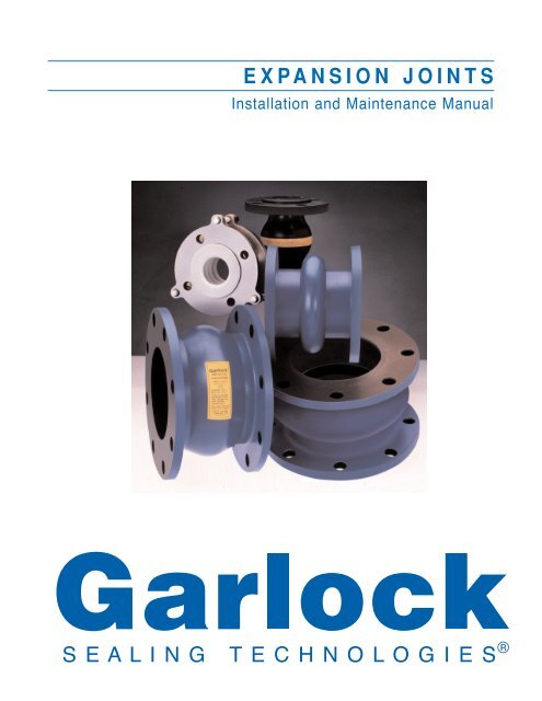
EXPANSION JOINTS<br />
Installation and Maintenance Manual
G<strong>AR</strong>LOCK SEALING TECHNOLOGIES<br />
Contents<br />
Elastomeric Expansion Joints<br />
Definition and Function . . . . . . . . . . . . . . . . . . . . . . 1<br />
Construction Details . . . . . . . . . . . . . . . . . . . . . . . . . 1<br />
Design Types . . . . . . . . . . . . . . . . . . . . . . . . . . . . . 2<br />
Control Units<br />
Definition and Purpose . . . . . . . . . . . . . . . . . . . . . . 6<br />
Standard Design . . . . . . . . . . . . . . . . . . . . . . . . . . . 6<br />
Special Design . . . . . . . . . . . . . . . . . . . . . . . . . . . . 7<br />
Measuring and Evaluating Misalignment<br />
Flange-to-Flange Dimensions . . . . . . . . . . . . . . . . . 8<br />
Angular Misalignment . . . . . . . . . . . . . . . . . . . . . . . 8<br />
Lateral Misalignment . . . . . . . . . . . . . . . . . . . . . . . . 9<br />
Torsional Misalignment . . . . . . . . . . . . . . . . . . . . . 10<br />
Concurrent Misalignment . . . . . . . . . . . . . . . . . . . . 10<br />
Installation Procedures<br />
Removal of Old Expansion Joints . . . . . . . . . . . . . . 11<br />
Joint Handling and Transporting . . . . . . . . . . . . . . . 11<br />
Preparation for Installation . . . . . . . . . . . . . . . . . . . 11<br />
Joint Installation . . . . . . . . . . . . . . . . . . . . . . . . . . . 11<br />
Control Unit Installation . . . . . . . . . . . . . . . . . . . . . 12<br />
Maintenance Procedures<br />
Visual and Physical Inspection . . . . . . . . . . . . . . . 14<br />
Troubleshooting Control Units . . . . . . . . . . . . . . . . 14<br />
Life Expectancy of Elastomeric Joints<br />
Storage Instructions . . . . . . . . . . . . . . . . . . . . . . . . 15<br />
Shelf Life . . . . . . . . . . . . . . . . . . . . . . . . . . . . . . . . 15<br />
Replacement Schedule . . . . . . . . . . . . . . . . . . . . . 15<br />
Appendix<br />
Tables I-V . . . . . . . . . . . . . . . . . . . . . . . . . . . . . . . 16
ELASTOMERIC EXPANSION JOINTS<br />
Definition and Function<br />
1. Flexible Connector - An elastomeric <strong>expansion</strong> joint<br />
is a specially designed section of pipe inserted within<br />
a rigid piping system to provide flexibility.<br />
2. Stress Relief - Pipe stress caused by thermal<br />
<strong>expansion</strong>/contraction or foundation settlement can<br />
be handled by <strong>expansion</strong> <strong>joints</strong>.<br />
3. Minor Misalignment - Standard <strong>expansion</strong> <strong>joints</strong><br />
can withstand a minimal amount of existing lateral,<br />
torsional, angular or concurrent misalignment.<br />
Contact the manufacturer for specifics.<br />
4. Isolate/Reduce Vibration - Oscillating movement<br />
around the axis of the <strong>expansion</strong> joint can be effectively<br />
dampened, eliminating the transmission of<br />
this vibration - preventing equipment damage/failure.<br />
5. Dampen Sound Transmission - Using rubber<br />
flanges, <strong>expansion</strong> <strong>joints</strong> can lower the transmission<br />
of undesirable noises.<br />
6. Multiple Arch Type - Expansion <strong>joints</strong> with up to<br />
four arches may be manufactured to handle greater<br />
movements than a single arch. The movement capability<br />
of a multiple arch <strong>expansion</strong> joint is typically<br />
that of a single arch type multiplied by the number of<br />
arches. (See Figures 1, 2 & Table I)<br />
Construction Details<br />
Elastomeric <strong>expansion</strong> <strong>joints</strong> are constructed of three<br />
basic elements: the tube, the body or carcass, and the<br />
cover. The construction details are shown in Figures 1-4<br />
and each element is defined as follows:<br />
1. Tube - Consists of a protective, leakproof lining<br />
which may be made of synthetic or natural rubber,<br />
depending on operating conditions. The tube is<br />
seamless and it extends through the bore of the<br />
joint to the outside edges of the flanges. Its purpose<br />
is to eliminate the possibility of the materials being<br />
handled from penetrating the carcass and weakening<br />
the fabric. Tubes can be designed to handle a wide<br />
range of service conditions for chemical, petroleum,<br />
sewage, gaseous, and abrasive materials. When<br />
evaluating a specific application, the media will<br />
7. Natural/Synthetic Elastomer - A wide variety of<br />
elastomers are available to meet specific demands<br />
of industrial applications.<br />
8. Fabric/Metal Reinforced - The strength in an<br />
elastomeric <strong>expansion</strong> joint is derived from design<br />
features, combined with rubber impregnated layers<br />
of fabric and internal metal reinforcement. (See<br />
Figures 1 & 2)<br />
9. Fabric Reinforcement - In these styles, wide flowing<br />
arch (Figure 3) and U-type (Figure 4), fabric is<br />
used to effectively handle design parameters outlined.<br />
10. Resistance To Corrosive Media - Special elastomeric<br />
liners and covers may be utilized to prolong<br />
life of the <strong>expansion</strong> joint when corrosives are<br />
present.<br />
11. Resistance To Abrasive Media - Abrasive media<br />
may be handled more effectively if a special<br />
tube/liner is used; ie: gum rubber, increasing thick<br />
ness of layers (rubber), steel flow liner, etc.<br />
12. Temperature Capability - Depending on the elastomer<br />
selected, elastomeric <strong>expansion</strong> <strong>joints</strong> can<br />
handle a range of -40°F (-40°C) to 400°F (205°C).<br />
dictate the type of elastomer needed; ie:<br />
fluoroelastomer (VITON ® ), FEP fluorocarbon, nitrile,<br />
EPDM, HYPALON ® , chlorobutyl, gum rubber, or<br />
neoprene elastomers are frequently specified.<br />
FDA- approved materials such as white neoprene<br />
or white EPDM elastomers are also available.<br />
2. Body or Carcass - Consists of fabric/metal<br />
reinforcement. Expansion <strong>joints</strong> with a combination<br />
of fabric and metal reinforcement are shown in<br />
Figures 1 & 2. The <strong>expansion</strong> <strong>joints</strong> in Figures 3 &<br />
4 have fabric reinforcement only.<br />
VITON and HYPALON are registered trademarks of DuPont Dow<br />
Elastomers.<br />
1
Construction Details (cont’d)<br />
2<br />
a. Fabric Reinforcement - The flexible and<br />
supporting member between the tube and<br />
cover. Standard constructions normally utilize high<br />
quality synthetic fabric such as polyester, nylon<br />
tire cord or fiberglass/KEVL<strong>AR</strong> ® . Natural fabrics<br />
are also used depending on temperature and<br />
pressure requirements. All fabric plies are<br />
impregnated with a compatible elastomer in<br />
order to maintain a superior bond as well as<br />
flexibility.<br />
b. Metal Reinforcement - Consists of solid steel<br />
rings imbedded in the carcass of the <strong>expansion</strong><br />
joint. The steel rings reinforce the <strong>expansion</strong><br />
joint and provide the dimensional stability needed<br />
Design Types<br />
The design types of elastomeric <strong>expansion</strong> <strong>joints</strong><br />
are shown in Figures 1 thru 4. The benefits of each<br />
type are described:<br />
Open Arch Expansion Joint<br />
Figure 1 shows a standard spool<br />
type <strong>expansion</strong> joint. The joint has one<br />
open abrupt arch, which is utilized to<br />
absorb movements in piping systems.<br />
The flanges of the <strong>expansion</strong> joint are<br />
integral with the body and are drilled to<br />
conform to the bolting pattern of the<br />
metal flanges of the pipe line. This type<br />
of rubber faced flange is of sufficient<br />
thickness to form a leakproof seal<br />
against the metal flanges without the<br />
use of gaskets.<br />
Expansion <strong>joints</strong> with two or more<br />
arches may be manufactured to<br />
accommodate greater movement.<br />
Multiple arch <strong>expansion</strong> <strong>joints</strong> are<br />
capable of handling the movements of<br />
a single arch <strong>expansion</strong> joint multiplied<br />
by the number of arches.<br />
KEVL<strong>AR</strong> is a registered trademark of DuPont.<br />
Face-to-Face (FF)<br />
for pressure or vacuum service. They are formed<br />
from AISI 1018 or other high strength materials<br />
and are either round or rectangular (see<br />
Figures 1 & 2).<br />
3. Cover - A homogeneous layer of rubber com-<br />
pound bonded to the exterior of the <strong>expansion</strong><br />
joint. The prime function of the cover is to protect<br />
the carcass from outside damage. Special<br />
elastomers can be supplied to resist chemicals<br />
oils, sunlight, acid, fumes, and ozone. Environ-<br />
mental conditions will dictate the exterior of<br />
the <strong>expansion</strong> joint for additional protection.<br />
Therefore, movement dictates the number of arches<br />
required, subsequently the number of arches dictates<br />
face-to-face allowance. See Appendix, Table I for<br />
added information on face-to-face dimensions and typical<br />
movement capabilities of open arch <strong>expansion</strong><br />
<strong>joints</strong>.<br />
Flange O.D.<br />
Bolt Circle Diameter<br />
Joint I.D.<br />
Figure 1<br />
Cross sectional view of single open arch <strong>expansion</strong> joint.<br />
Bolt Hole<br />
Diameter<br />
Bolt Hole<br />
Tube<br />
Carcass Fabric<br />
Reinforcement<br />
Carcass Metal<br />
Reinforcement<br />
Cover
Design Types (cont’d)<br />
The <strong>expansion</strong> joint is reinforced with fabric plies<br />
and round or rectangular body rings. The number of fabric<br />
plies and metal rings is directly proportional to the<br />
pressure rating of the <strong>expansion</strong> joint. Utilization of<br />
metal body rings provides the dimensional stability<br />
needed for vacuum and pressure service. Typical pressure<br />
and vacuum ratings of <strong>expansion</strong> <strong>joints</strong> in Figure 1<br />
are listed in Appendix, Table V. Service temperature of<br />
the <strong>expansion</strong> joint depends on the materials of construction.<br />
Filled Arch Expansion Joint<br />
The open arch design of Figure 1 may be modified to<br />
reduce turbulence and to prevent the entrapment of solids.<br />
Shown in Figure 2 is a standard arch type elastomeric<br />
<strong>expansion</strong> joint manufactured with a bonded, lower durometer<br />
rubber arch filler to provide a smooth interior bore.<br />
Filled arches built as an integral part of the carcass<br />
decrease the flexibility of the joint and should be used only<br />
when necessary. Using a filled arch <strong>expansion</strong> joint<br />
reduces movement capabilities by 50%.<br />
Face-to-Face (FF)<br />
Flange O.D.<br />
Bolt Circle Diameter<br />
Joint I.D.<br />
Soft<br />
Arch<br />
Filler<br />
Expansion <strong>joints</strong> constructed of polyester fabric and<br />
chlorobutyl are rated for temperatures up to 250°F<br />
(121°C). EPDM and fiberglass/KEVL<strong>AR</strong> ® fabric allows<br />
for up to 300°F (149°C) service. When constructed of<br />
fiberglass/KEVL<strong>AR</strong> ® fabric and fluoroelastomer they<br />
can withstand temperatures up to 400°F (204°C).<br />
Always contact the manufacturer before specifying<br />
and purchasing <strong>expansion</strong> <strong>joints</strong> for your specific application.<br />
Filled arch <strong>expansion</strong> <strong>joints</strong> can be constructed to handle<br />
the same temperature, pressure and vacuum requirements<br />
as open arch <strong>expansion</strong> <strong>joints</strong>. For typical pressure<br />
and vacuum capabilities, refer to Appendix, Table V.<br />
Bolt Hole<br />
Diameter<br />
Bolt Hole<br />
Tube<br />
Carcass Fabric<br />
Reinforcement<br />
Carcass Metal<br />
Reinforcement<br />
Cover<br />
Figure 2<br />
Cross sectional view of filled arch <strong>expansion</strong> joint. KEVL<strong>AR</strong> is a registered trademark of DuPont.<br />
3
Design Types (cont’d)<br />
Flowing Arch Expansion Joint<br />
Figure 3 shows a self-flushing or flowing arch <strong>expansion</strong><br />
joint. The streamlined flowing arch reduces turbulence<br />
and allows smooth, quiet flow. There is no possibility<br />
of sediment build-up and no need to fill the arch, so<br />
movement is not restricted.<br />
The <strong>expansion</strong> joint is constructed of high strength<br />
nylon tire cord without any metal reinforcement. As a<br />
result, the <strong>expansion</strong> joint is very flexible, with up to 30%<br />
greater ability to absorb compression movement over the<br />
open arch <strong>expansion</strong> joint. For added information on<br />
movement capabilities of the flowing arch <strong>expansion</strong><br />
<strong>joints</strong>, refer to Appendix, Table I.<br />
4<br />
Face-to-Face (FF)<br />
Flange O.D.<br />
Bolt Circle Diameter<br />
Joint I.D.<br />
Figure 3<br />
Cross sectional view of flowing arch <strong>expansion</strong> joint.<br />
The nylon tire cord fabric provides an exceptionally<br />
high temperature range of -40°F (-40°C) to 250°F (121°C).<br />
The high-strength fabric also produces an <strong>expansion</strong> joint<br />
with an exceptional burst pressure rating; however, without<br />
metal reinforcement, its vacuum rating is reduced. See<br />
Appendix, Table V for typical pressure and vacuum ratings<br />
of flowing arch <strong>expansion</strong> <strong>joints</strong>.<br />
Bolt Hole<br />
Diameter<br />
Bolt Hole<br />
Tube<br />
Carcass Fabric<br />
Reinforcement<br />
Cover
Design Types (cont’d)<br />
U-Type Expansion Joint<br />
The U-type <strong>expansion</strong> <strong>joints</strong>, as shown in Figure 4, are<br />
primarily designed for full vacuum service with a maximum<br />
pressure rating of 25 psig (1.7 bar) and temperature of<br />
250°F (121°C). These <strong>joints</strong> are constructed of several<br />
plies of polyester fabric and rubber without metal reinforcement.<br />
Face-to-Face (FF)<br />
Flange O.D.<br />
Bolt Circle Diameter<br />
Without an arch, the <strong>expansion</strong> <strong>joints</strong> have limited<br />
movement capability and are primarily recommended for<br />
the reduction of vibration and noise. They can be furnished<br />
with narrow face-to-face dimensions and often<br />
require staggered bolt hole drilling. Typical movement<br />
capabilities of U-type <strong>expansion</strong> <strong>joints</strong> are listed in<br />
Appendix, Table ll.<br />
Joint I.D. Bolt Hole Diameter<br />
Figure 4<br />
Cross sectional view of U-type <strong>expansion</strong> joint.<br />
Bolt Hole<br />
Tube<br />
Carcass Fabric<br />
Reinforcement<br />
Cover<br />
5
CONTROL UNITS<br />
Definition and Purpose<br />
A control unit is a system of two or more control rod<br />
(tie rod) assemblies placed across an <strong>expansion</strong> joint from<br />
flange to flange to prevent possible damage to the <strong>expansion</strong><br />
joint caused by excessive motion of the pipeline.<br />
Control units are always recommended since this excessive<br />
pipe motion could be caused by failure of an anchor<br />
or some other piece of equipment in the pipeline and<br />
would result in a catastrophic failure of the <strong>expansion</strong> joint<br />
if not used.<br />
Control units are not designed to replace recommended<br />
anchoring of a pipeline, but they must be used when<br />
proper anchoring cannot be provided. By restraining the<br />
Standard Design<br />
Figure 5 shows the proper assembly of an <strong>expansion</strong><br />
joint with standard design control units. The control<br />
unit system consists of a minimum of two tie rods<br />
with triangular plates and hex nuts with steel and rubber<br />
washers. The exact number and diameter of the tie<br />
rods and the thickness of the triangular plates is selected<br />
on the basis of the actual design/test pressure and<br />
other load requirements the system may be subjected<br />
6<br />
Bolt Circle<br />
Diameter<br />
Hex Nuts<br />
Joint O.D.<br />
Equally<br />
Spaced<br />
Bolt Holes<br />
Joint I.D.<br />
E<br />
piping system, the control unit will adequately protect the<br />
<strong>expansion</strong> joint from excessive elongation and compression<br />
movements caused by static pressure thrust or any<br />
other load.<br />
Rubber <strong>expansion</strong> <strong>joints</strong> are not designed to take end<br />
thrusts. In all cases where such are likely to occur, control<br />
units must be used to restrain the piping system. The control<br />
rod assemblies are set at the maximum allowable<br />
<strong>expansion</strong> and/or contraction of the <strong>expansion</strong> joint. When<br />
used in this manner, they are an additional safety factor,<br />
preventing catastrophic failure of the <strong>expansion</strong> joint and<br />
minimizing possible damage to the equipment.<br />
to. Always specify all load requirements when ordering<br />
control unit assemblies.<br />
The tie rods are usually fabricated from highstrength<br />
ASTM A193-B7 alloy bolts. They are set for<br />
the maximum allowable elongation of an <strong>expansion</strong><br />
joint and are designed to accept the static pressure<br />
thrust in addition to other external loads which would<br />
cause the joint to over-elongate.<br />
Figure 5<br />
Expansion joint with assembly of standard control unit components.<br />
C<br />
FF<br />
Expansion Joint<br />
Optional Compression<br />
Sleeve<br />
Control Rod<br />
Rubber Washer<br />
Steel Washer<br />
Pipe Flange<br />
Control Rod Plate
Standard Design (cont’d)<br />
The maximum elongation setting “E” shown in Figure<br />
5 is based on each <strong>expansion</strong> joint's design and will vary<br />
for different manufacturers. Refer to Table I for typical<br />
elongation requirements for single or multiple arch <strong>expansion</strong><br />
<strong>joints</strong>.<br />
Overcompression of <strong>expansion</strong> <strong>joints</strong> is controlled by<br />
installing compression sleeves over the tie rods. The<br />
compression sleeves are usually made from commercially<br />
available black iron pipe. The length of the pipe sleeve<br />
should be such that the <strong>expansion</strong> joint cannot be compressed<br />
beyond its maximum allowable capabilities. This<br />
allowable movement is the setting “C” of Figure 5 and is<br />
based on design requirements stated by the <strong>expansion</strong><br />
joint manufacturer. Table I lists typical compression<br />
movements for single or multiple arch <strong>expansion</strong> <strong>joints</strong>.<br />
Note: The control unit settings E and C are based on<br />
the <strong>expansion</strong> joint installed at neutral manufactured<br />
lendth “FF” with pipe flange alignment of<br />
±1/8" (0.125mm) maximum.<br />
The triangular plates for control units are usually<br />
fabricated from ASTM A-36 plates or other high-strength<br />
plate materials. The plates are drilled with three holes,<br />
two of which are used for bolting the plate to the pipe<br />
Special Design<br />
Figure 6 shows an <strong>expansion</strong> joint with an assembly<br />
of control unit components with spherical washers. This<br />
special design is suitable for applications where greater<br />
control of piping movements is required.<br />
As shown in Figure 6, the movement of the pipe<br />
flanges is restricted to transverse deflection only. This is<br />
made possible by the spherical washers on both sides of<br />
the triangular plates. By tightening the spherical washers<br />
against the plate at both ends of the tie rods, compression<br />
and elongation of the <strong>expansion</strong> joint is eliminated.<br />
The elimination of axial movement may be required to<br />
control stress in the pipeline or equipment.<br />
If, in another application, axial movement of the pipe<br />
flanges must be provided, then the hex nuts are adjusted<br />
to allow the <strong>expansion</strong> joint to compress and elongate as<br />
required. The inner hex nuts are set to control compression<br />
of the <strong>expansion</strong> joint. The outer hex nuts are set to<br />
control elongation of the <strong>expansion</strong> joint. Once the hex<br />
nuts are set, the threads of the tie rods are “staked” and<br />
the control units function in the same manner as the control<br />
units of Figure 5.<br />
flange. The third hole is for the tie rod which connects<br />
the plate on each end of the <strong>expansion</strong> joint. To dampen<br />
noise and vibration, rubber washers are used<br />
between the plate and the rod. The rubber washers are<br />
typically made of a 1/4" (0.25mm) thick 80 shore A<br />
durometer rubber.<br />
To evenly distribute the load from the hex nuts<br />
(ASTM 194-2H) against the rubber washer, steel washers<br />
are used, as shown in Figure 5. The steel washers<br />
are US Standard washers with an I.D. and O.D. to<br />
match the dimensions of the rubber washers. Once the<br />
control units are installed and set, it is critical that the<br />
setting is not altered during the service life of the joint.<br />
Vibration of the piping system can often loosen and<br />
gradually turn the hex nuts, changing the critical setting<br />
of the control units. To prevent the turning of the hex<br />
nuts, the threads of the tie rods are “staked” on each<br />
side of the hex nut.<br />
Notes: 1. Control units do not protect the <strong>expansion</strong><br />
<strong>joints</strong> against lateral offsets. Piping must be<br />
anchored and supported.<br />
2. Do not use control units with non-metallic<br />
flanges which do not have sufficient strength.<br />
Steel Spherical Washers<br />
Control Rods<br />
Hex Nuts<br />
Control Rod Plate<br />
Retaining Ring<br />
Expansion Joint<br />
Pipe Flange<br />
Figure 6<br />
Expansion Joint with assembly/installation of control unit<br />
components with spherical washers.<br />
7
MEASURING AND EVALUATING MISALIGNMENT<br />
Before any <strong>expansion</strong> <strong>joints</strong> are to be replaced,<br />
dimensions must be verified. As a result of settlement,<br />
misalignment or improper design, many elastomeric<br />
<strong>expansion</strong> <strong>joints</strong> are overstressed beyond their performance<br />
limitations. It is critical, therefore, that all<br />
measurements (flange-to-flange, lateral, torsional, and<br />
angular misalignment) be double-checked against original<br />
specifications/drawings.<br />
Flange-to-Flange Dimensions<br />
(also known as face-to-face or FF)<br />
This measurement is taken from the inside of one<br />
mating metal flange to the inside of the other – the<br />
actual opening where the <strong>expansion</strong> joint is to be<br />
inserted. This is typically the dimension most likely to be<br />
variable. For example, if the original <strong>expansion</strong> joint<br />
measured 8" FF, but the current opening measures 9-<br />
1/2" FF, it is necessary to build the <strong>expansion</strong> joint at the<br />
new FF dimension. Most elastomeric <strong>expansion</strong> <strong>joints</strong><br />
are rated for a minimal amount of elongation (1/4-1/2")<br />
and, therefore, the <strong>expansion</strong> joint would be overstressed<br />
if installed at 1-1/2" more than the manufactured<br />
dimension. This stress would begin internally as the<br />
vulcanized fabric plies began to tear apart. Evidence of<br />
such stress would be cracking/tearing at the base of the<br />
elastomeric flanges and delamination of fabric plies<br />
under pressure/vaccuum. Subjecting an <strong>expansion</strong> joint<br />
to this type of condition will shorten its life expectancy<br />
and may cause premature failure.<br />
Conversely, if an <strong>expansion</strong> joint is manufactured at<br />
8" FF, and the actual opening between the mating metalflanges<br />
is 7-1/4" FF, it is practically impossible to<br />
precompress the joint without incurring damage.<br />
Elastomeric <strong>expansion</strong> <strong>joints</strong> are designed to handle<br />
gradual axial movements as a result of thermal<br />
<strong>expansion</strong> and contraction. Forcing an <strong>expansion</strong> joint in<br />
place puts an unnatural stress on the elastomeric<br />
flanges causing internal damage, especially along the<br />
back of the flange area and the arch.<br />
The flange-to-flange dimension becomes a critical<br />
factor when replacing an <strong>expansion</strong> joint, but also, when<br />
measured accurately, may enhance the life expectancy<br />
of the product. When measured incorrectly, it may<br />
greatly reduce the performance of the <strong>expansion</strong> joint<br />
and may even contribute to a premature/catastrophic<br />
failure.<br />
8<br />
Maximum allowable misalignment is listed in Appendix,<br />
Table IV; however, greater tolerances may be permitted. It<br />
is advisable to check with the manufacturer before exceeding<br />
this industry standard.<br />
Angular Misalignment<br />
When measuring the flange-to-flange dimension, it is<br />
necessary take a minimum of four dimensions; on larger<br />
I.D. <strong>expansion</strong> <strong>joints</strong> (over 24") six to eight measurements<br />
are recommended. If measuring in four areas, they should<br />
be spaced equally around the circumference of the<br />
<strong>expansion</strong> joint (in opposing quadrants). Any variation in<br />
the dimensions taken are indicative of angular<br />
misalignment – the non-parallelism of the mating metal<br />
flanges.<br />
There are other important notations to make, if angular<br />
misalignment is present. Since one of the main difficulties<br />
in installing an <strong>expansion</strong> joint (especially on 24" I.D. and<br />
larger) is accessibility, it is valuable to indicate on the<br />
measurements taken where the access point would be. If<br />
the access point is dramatically smaller than the opposing<br />
side, the <strong>expansion</strong> joint face-to-face must be built to the<br />
access point measurement. However, the <strong>expansion</strong> joint<br />
must have the ability to extend beyond the longest face-toface<br />
flange dimension without damage. There are other<br />
ways to handle this angular misalignment; i.e. using<br />
tapered metal spacers, and realigning the piping. Be sure<br />
to contact the manufacturer for their recommendations<br />
(see Figure 7 for illustration).
Angular Misalignment (cont’d)<br />
7A<br />
Angular<br />
Misalignment<br />
7B<br />
FF1<br />
Lateral Misalignment<br />
FF1<br />
This condition is apparent when pipe center lines<br />
are not aligned. Inadequate pipe support or settling of<br />
equipment is typically the cause for this condition.<br />
When measuring for lateral misalignment, a level<br />
and a rule are needed. Place the level on the outside<br />
of one of the metal flanges across to the other and<br />
measure the difference between them. As in the case<br />
of angular misalignment, a minimum of four<br />
measurements is recommended on smaller <strong>joints</strong>.<br />
Expansion <strong>joints</strong> with larger inside diameters (over 24")<br />
require six to eight measurements taken equally<br />
spaced around the outside circumference of the flange.<br />
Special Lateral Offset<br />
Expansion Joint<br />
L<br />
A<br />
FF2<br />
Figure 7<br />
Angular misalignment of pipe flanges.<br />
Figure 8<br />
Lateral misalignment of pipe flanges.<br />
Special Angular<br />
Offset Joint<br />
FF1 FF2<br />
Minor amounts of lateral misalignment can be<br />
corrected with standard <strong>expansion</strong> <strong>joints</strong> (see<br />
Appendix, Table IV for limitations and Figure 7 for<br />
illustration). For lateral misalignment beyond<br />
recommended limitations, special <strong>expansion</strong> <strong>joints</strong> can<br />
be manufactured to facilitate installation. Another option<br />
for correcting lateral misalignment is to realign the pipe.<br />
Be sure to contact the manufacturer for their<br />
recommendations.<br />
Rubber Flange<br />
Metal Flange<br />
Lateral<br />
Misalignment<br />
8A 8B 8C<br />
Rubber Flange<br />
Metal Flange<br />
L<br />
9
Torsional Misalignment<br />
This condition occurs when rotation of the pipe<br />
flange causes bolt holes to be out of line (see Figure 9<br />
for illustration). Minor torsional misalignment can be<br />
handled using a standard <strong>expansion</strong> joint; however,<br />
severe torsional misalignment requires an <strong>expansion</strong><br />
joint with the degree of torsional offset built-in (see<br />
Appendix Table IV for limitations and Figure 9 for illustration).<br />
As an alternative, realign the pipe flanges or drill<br />
the <strong>expansion</strong> joint on-site. Contact the manufacturer for<br />
tooling and instructions.<br />
10<br />
Figure 9<br />
Torsional misalignment of metal flanges<br />
9A 9B<br />
T<br />
Concurrent Misalignment<br />
Special <strong>expansion</strong> <strong>joints</strong> are required for combinations<br />
of severe lateral and angular misalignment. This<br />
condition requires exact measurements along with the<br />
location of the misalignment measured. To best accommodate<br />
this situation, drawings that detail these measurements<br />
should be provided with the order. If assistance<br />
is required, contact the manufacturer for a survey<br />
of the <strong>expansion</strong> <strong>joints</strong>.<br />
When ordering offset <strong>expansion</strong> <strong>joints</strong>, they must be<br />
properly identified with a customer equipment number.<br />
The manufacturer must also mark the center line of the<br />
flange face as well as the back of the joint flange. This<br />
will ensure proper location and ease of installation.<br />
Rubber Flange<br />
Metal Flange<br />
Rotation of<br />
Metal Flange
INSTALLATION PROCEDURES<br />
Removal of Old Expansion Joints<br />
1. Measurements - Prior to removing old <strong>expansion</strong><br />
<strong>joints</strong>, accurate measurements of the system should<br />
be taken. Measure the face-to-face dimension of<br />
the <strong>expansion</strong> joint and check the flanges for any<br />
misalignment such as lateral, torsional and/or angular.<br />
Refer to pages 8 thru 10 for measuring and<br />
evaluating misalignment.<br />
2. Pipe Anchors/Supports - Carefully inspect pipe<br />
anchors and flange supports before removing old<br />
<strong>expansion</strong> <strong>joints</strong>. Over the years pipe supports and<br />
anchors may become loose and the <strong>expansion</strong> joint<br />
may actually be supporting the pipe.<br />
3. Breaking Seal - With elastomeric <strong>joints</strong> it is important<br />
to break the seal of both flanges before the<br />
joint is removed. Forced removal with an unbroken<br />
seal may result in damage to the metal flange. To<br />
break the seal, drive small wooden wedges between<br />
the rubber flange of the joint and mating<br />
metal flange.<br />
Joint Handling and Transporting<br />
1. Expansion Joint Storage - An elastomeric <strong>expansion</strong><br />
joint should be stored in a cool, dry and dark<br />
place. Expansion <strong>joints</strong> can be stacked only when<br />
individually packaged in boxes or crates of sufficient<br />
strength. Expansion <strong>joints</strong> should always be posi<br />
tioned so that they are not resting or standing<br />
upright on their flange edges.<br />
2. Transportation of Large I.D. Joints - Care must<br />
be taken when transporting large <strong>expansion</strong> <strong>joints</strong><br />
from a storage area to the job site. Expansion <strong>joints</strong><br />
should never be rolled on their flanges or pulled<br />
with a cloth sling looped through the I.D. Large<br />
<strong>expansion</strong> <strong>joints</strong> should always be transported crated<br />
or on a platform laying in a horizontal position to<br />
prevent any possible damage. Once at the job site,<br />
the <strong>joints</strong> should always be laid flat on the floor and<br />
protected against damage.<br />
Preparation for Installation<br />
1. Area Accessibility - Installation of large I.D. <strong>expansion</strong><br />
<strong>joints</strong> requires a lot of manpower and an open,<br />
accessible area. Machinery or equipment which<br />
could complicate the installation must be removed.<br />
Sharp objects or rough surfaces which may damage<br />
the sealing surface of rubber flanges should be<br />
taped or removed ahead of time.<br />
2. Bolts/Fasteners - Used bolts and fasteners should<br />
be sand-blasted and inspected for damage.<br />
Corroded or damaged bolts should be replaced.<br />
Garlock also recommends the use of flat steel<br />
washers where joining retaining ring segments.<br />
3. Retaining Rings - Used split retaining rings must<br />
be checked for rust and warping. Rusted or corrod<br />
ed retaining rings should be corrected. Warped<br />
retaining rings should be replaced, since flatness of<br />
rings is critical for achieving and maintaining a seal.<br />
4. Mating Metal Flanges - Elastomeric <strong>expansion</strong><br />
<strong>joints</strong> must be mated against clean, smooth metal<br />
flanges. The mating metal flanges should be carefully<br />
examined for reasonable smoothness. Gouged or<br />
pitted flanges should be resurfaced or repaired. A<br />
suitable repair compound is Belzona “Super Metal”<br />
cement.<br />
5. Joint/Bolt Lubricants - The recommended lubricant<br />
for use with Garlock <strong>expansion</strong> ioints is a solution<br />
of graphite in water or glycerine. Another<br />
suitable <strong>expansion</strong> joint lubricant is Dow Corning<br />
DC-111, a silicone-based material. Any other joint<br />
lubricants must be approved by Garlock to insure<br />
chemical compatibility.<br />
Joint Installation<br />
1. Horizontal/Vertical Installation - Expansion <strong>joints</strong><br />
installed where metal flanges are in a horizontal<br />
position are first brought to the level of the flanges,<br />
then slid into place. Flanges may be lubricated to<br />
aid in sliding the <strong>expansion</strong> <strong>joints</strong> into place.<br />
Large <strong>expansion</strong> <strong>joints</strong> to be installed where<br />
metal flanges are in a vertical position will require<br />
hoisting into place. Hoisting of the joint can be<br />
accomplished with cloth slings. The joint must be<br />
looped on the outside with a separate loop formed<br />
on each side of the arch to prevent <strong>expansion</strong> joint<br />
damage.<br />
11
Joint Installation (cont’d)<br />
2. Piping Misalignment - Installation of <strong>expansion</strong><br />
<strong>joints</strong> may sometimes be complicated due to misalignment<br />
of the piping system.<br />
The allowable piping misalignments are shown<br />
in Appendix, Table IV. Figure 10 shows a method for<br />
installing standard <strong>expansion</strong> <strong>joints</strong> with minor lateral<br />
and torsional misalignment of the metal flanges.<br />
The methods shown in Figures 9 thru 11 can be<br />
used for lateral and torsional misalignment of 1/4"<br />
for up to 46" I.D. <strong>joints</strong> and 1/4" - 3/8" for larger I.D.<br />
<strong>joints</strong>. Greater lateral and torsional misalignments<br />
will require special <strong>expansion</strong> <strong>joints</strong>. Expansion<br />
<strong>joints</strong> can be built with lateral offset of flanges and<br />
they can be either special drilled or supplied with<br />
one flange undrilled for torsional misalignment prob<br />
lems. Garlock can provide the tooling and drilling<br />
procedures needed to drill elastomeric <strong>expansion</strong><br />
<strong>joints</strong> on-site.<br />
Angular misalignment of metal flanges is shown<br />
in Table V. The angular misalignment is determined<br />
from the smallest and the largest flange opening<br />
dimension FF 1 & FF 2 (Figure 7). Standard expan<br />
sion <strong>joints</strong> can be installed in flanges with minor mis<br />
alignment; refer to Table IV. When ordering standard<br />
<strong>expansion</strong> <strong>joints</strong>, the face-to-face of the <strong>expansion</strong><br />
joint must be specified such that the <strong>expansion</strong> joint<br />
will fit into the smaller dimension FF 1.<br />
Substantial angular misalignment of the metal<br />
flanges will require a special <strong>expansion</strong> joint built as<br />
shown in Figure 7.<br />
3. Bolting Sequence - Garlock <strong>expansion</strong> <strong>joints</strong> are<br />
supplied with segmented retaining rings. Bolting of<br />
the retaining rings and torquing of the bolts in each<br />
ring segment should be in the sequence illustrated in<br />
Figure 11. The objective is to bolt the entire retaining<br />
ring segment evenly and to compress the rubber<br />
flanges as uniformly as possible. The use of flat<br />
steel washers will help obtain an effective seal<br />
where the retaining rings are split.<br />
All bolts should be “snug” tight before they are<br />
torqued. Torquing should then be accomplished in<br />
steps gradually and as evenly as possible.<br />
12<br />
The bolts are not considered torqued and “lock<br />
on” until the edges of the <strong>expansion</strong> joint bulge out<br />
or extrude slightly. In many cases, especially on the<br />
larger sizes (I.D.'s), the flange portion may indent<br />
slightly.<br />
4. Maintaining Seal - Check bolt tightness at least<br />
one week after going on-line and periodically there<br />
after. As any rubberlike material takes a “set" after a<br />
period of compression, the bolts may loosen and<br />
require retorquing. It is particularly important to<br />
check bolts during temperature cycles or during<br />
shut-down times.<br />
Control Unit Installation<br />
Control units should be evenly distributed around the<br />
bolt circle of the <strong>expansion</strong> joint. The triangular plate of<br />
the control unit is bolted to the outside of the steel pipe<br />
flange using bolts equal to 1/8" -1/4" diameter smaller<br />
than the lower holes in the control unit plate.<br />
Insert control rods with washers through the top<br />
hole of the first triangular plate. Place compression<br />
sleeve (if required) over control rod. Insert control rod<br />
through second triangular plate. See Figure 5. Place<br />
washers and hex nuts on end of control unit rod.<br />
The control unit rod setting is equal to the combined<br />
dimensions of the <strong>expansion</strong> joint face-to-face, two pipe<br />
flange thicknesses, two thicknesses of control unit<br />
plates, four washer thicknesses, plus maximum elongation<br />
of the <strong>expansion</strong> joint. See Appendix, Table I.<br />
After control units are fully assembled, the exposed<br />
threads at the end of the control unit rod should be<br />
staked to prevent any loosening of the setting.
INSTALLATION PROCEDURES<br />
Lateral Misalignment<br />
10A<br />
10B<br />
10C<br />
Pipe Flange<br />
Rubber Flange<br />
Small Diameter Expansion Joint<br />
Two segments of retaining rings per flange<br />
11A<br />
Figure 10<br />
Installing rubber <strong>expansion</strong> <strong>joints</strong> with minor lateral and torsional<br />
misalignment of pipe flanges.<br />
Tapered Pin<br />
Steel Washer<br />
Split - 2 places<br />
Bolt Torqued<br />
In<br />
Torsional Misalignment<br />
Steel Washer (flat)<br />
Pipe Flange<br />
Split - 4 places<br />
Rubber Flange<br />
Split Retaining Ring<br />
Figure 11<br />
Bolting sequence for elastomeric <strong>expansion</strong> <strong>joints</strong>.<br />
11B<br />
Large Diameter<br />
Expansion Joint<br />
Four segments of<br />
retaining rings<br />
per flange<br />
13
MAINTENANCE PROCEDURES<br />
Visual and Physical Inspection of<br />
Expansion Joints<br />
Maintenance programs for elastomeric <strong>expansion</strong><br />
<strong>joints</strong> should consist of visual as well as physical inspections.<br />
These inspections will yield information pertaining<br />
to the condition of the <strong>expansion</strong> <strong>joints</strong>. Rubber <strong>expansion</strong><br />
<strong>joints</strong> will exhibit definite symptoms of premature<br />
failure which could be caused by unnatural stress placed<br />
on the <strong>expansion</strong> joint, typically the result of pipe misalignment.<br />
External inspections will assist in determining<br />
the mode of failure. Internal inspections also contribute to<br />
evaluations, when possible, during outages or when the<br />
<strong>expansion</strong> joint is removed for equipment repairs.<br />
Inspection Criteria<br />
1. Inspection of the tube (internal) - The tube portion<br />
is the most critical part of the <strong>expansion</strong> joint, as this<br />
material comes in direct contact with the media. Any<br />
<strong>expansion</strong> joint which has a damaged tube must be<br />
replaced.<br />
14<br />
a. The joint as a whole may feel soft and spongy.<br />
Typically there is a break in the tube area and the<br />
media has saturated the fabric.<br />
b. Visual examination of the tube may also show thin<br />
areas or even exposed fabric, where the rubber<br />
has been worn away by the flow. This is indicative<br />
of an abrasion problem.<br />
c. Cracking or hardened rubber on the inside usually<br />
indicates excessive temperature. Check temperature<br />
rating of material.<br />
2. External Inspections<br />
a. Leaking at the flange - Upon initial installation,<br />
rubber will set and bolts may need retightening. If<br />
leakage persists, double check the mating flange<br />
for gouges or voids which may affect a seal. Note:<br />
be sure to mate rubber <strong>expansion</strong> <strong>joints</strong> with full<br />
face flat flanges.<br />
b. Cracking on the outside cover - The cover portion<br />
of the joint is rubber and can be changed if<br />
needed to provide compatibility with the environment.<br />
Surface cracking on the outside of the joint<br />
could be the result of environmental attack or<br />
old age.<br />
c. Cracking at the base of the flange - The most<br />
frequent causes of failure are over-elongation<br />
and lateral misalignment. Both are indicated by<br />
cracking at the base of the flange, which is the<br />
most critical stress point. Look carefully to determine<br />
severity. The fabric of the joint will be ex-<br />
posed and broken in the most severe cases.<br />
This is an extremely critical situation and the<br />
joint should be replaced immediately. Measure<br />
the face-to-face and lateral misalignment, order<br />
the proper size (face-to-face) and build-in offset.<br />
d. Delamination - Ply separation is a typical<br />
reaction of materials subjected to unnatural or<br />
excessive movement. This condition is evident<br />
by soft spots. Torsional misalignment and/or<br />
movement are usually the causes for this condition.<br />
Expansion <strong>joints</strong> which show signs of<br />
delamination should be watched carefully and<br />
replaced as soon as possible.<br />
e. Broken body rings - When an <strong>expansion</strong> joint<br />
has been subjected to pressure surges beyond<br />
its capabilities, the metal body rings inside<br />
may break. A slight bulge can be felt between<br />
the arch and the flange area, where the rings are<br />
located. The <strong>expansion</strong> joint should be replaced,<br />
since the structural integrity and dimensional stability<br />
of the <strong>joints</strong> is suspect under these circumstances,<br />
and some <strong>expansion</strong> <strong>joints</strong> do not contain<br />
metal body rings. These <strong>joints</strong> will tend to<br />
balloon under excessive pressure situations and<br />
should be replaced.<br />
Troubleshooting Control Units<br />
The control unit assembly is an added safety<br />
feature which is used to prevent over-elongation and<br />
overcompression of the <strong>expansion</strong> joint (see description<br />
of control units, pages 6 thru 7). If over-elongation<br />
has occurred the rubber washers will be extruded. In<br />
extreme cases, the plates will be bent at an angle.<br />
Consult the manufacturer for assistance. Environmental<br />
attack may cause corrosion on the metal surface of the<br />
control unit. Be sure to order materials compatible with<br />
the atmosphere.
LIFE EXPECTANCY OF ELASTOMERIC JOINTS<br />
The life expectancy of an elastomeric <strong>expansion</strong><br />
joint is based on many factors.<br />
1. Service Conditions<br />
a. Temperature<br />
b. Pressure<br />
c. Movement<br />
d. Number of Cycles<br />
e. Environmental Conditions<br />
f. Media - Abrasive, Chemical<br />
g. Flow Rate<br />
2. Presence of Misalignment<br />
3. Proper Installation<br />
4. Proper Storage<br />
If the service conditions are not severe, no misalignment<br />
is present, the <strong>expansion</strong> <strong>joints</strong> are stored<br />
and installed properly, the estimated life expectancy of<br />
an elastomeric <strong>expansion</strong> joint is approximately five<br />
years.<br />
As stated in this manual, if, however, <strong>expansion</strong><br />
<strong>joints</strong> are subjected to harsh service conditions, severe<br />
misalignment, installed or stored improperly or anycombination<br />
thereof, this predicted life will decrease<br />
proportionately.<br />
Storage Instructions<br />
In order to obtain complete shelf life, elastomeric<br />
<strong>expansion</strong> <strong>joints</strong> must be stored properly.<br />
1. Store in a cool, dry area.<br />
2. Store Iying on one flange face.<br />
3. Protect the flange faces and tube from nicks,<br />
cuts, dents, etc.<br />
4. Do not expose to greases, oils or solvents in<br />
liquid or vapor form.<br />
5. Prevent exposure to ultraviolet (UV) light from<br />
sunlight or strong fluorescent lights.<br />
6. Do not store near devices which produce<br />
ozone (O3).<br />
7. Do not place other objects on the top flange of<br />
the <strong>expansion</strong> joint.<br />
8. Following extended storage, C<strong>AR</strong>EFULLY<br />
inspect the joint for damage.<br />
9. If in doubt concerning any of the above<br />
provisions, consult the manufacturer.<br />
Shelf Life<br />
Based on ideal storage conditions, the shelf life of<br />
an elastomeric <strong>expansion</strong> joint is five years from the<br />
date of manufacture.<br />
If this time period is exceeded, some degenerative<br />
processes may take place; i.e. embrittlement, cracking,<br />
restriction of movement capabilities, etc.<br />
Should <strong>expansion</strong> <strong>joints</strong> be stored at less than<br />
ideal conditions, this five year shelf life must be<br />
reduced proportionately. (See storage instructions.)<br />
Shelf life mustbe taken into consideration when predicting<br />
the life expectancy of elastomeric <strong>expansion</strong> <strong>joints</strong><br />
– if stored in less than ideal conditions, the expected<br />
service life would decrease accordingly.<br />
Replacement Schedule<br />
Since the typical life expectancy of an elastomeric<br />
<strong>expansion</strong> joint is five years, preventive maintenance<br />
schedules should be enacted accordingly.<br />
If, however, excessive misalignment is present,<br />
causing the <strong>expansion</strong> joint to undergo significant<br />
stress, this schedule must be adjusted.<br />
When the <strong>expansion</strong> <strong>joints</strong> are subjected to<br />
extreme or harsh conditions, i.e. high pressure, excessive<br />
movement/cycling, abrasion, etc., inspection procedures<br />
need to be done at more timely intervals,<br />
beginning at the end of the first year in service and<br />
continuing on an ongoing basis. If the service is critical,<br />
an accelerated inspection schedule is suggested.<br />
If the <strong>expansion</strong> joint demonstrates signs of fatigue,<br />
replace it as soon as possible. If no physical/visible<br />
signs of distress are present, the <strong>expansion</strong> joint<br />
should be replaced every five years. The strength of<br />
the <strong>expansion</strong> joint is in the internal structuring of its<br />
layers; deterioration of these strengthening plies is not<br />
always apparent.<br />
15
APPENDIX<br />
Table I<br />
Typical Dimensions and Movement<br />
Capabilities for Rubber Expansion Joints<br />
Joint Size (Inside Dia.) 1 1 1 1 ⁄4 1 1 ⁄2 2 2 1 ⁄2 3 4 5 6 8 10 12 14 16 18 20 22 24 26 28 30 34 36<br />
Flange Outside Dia. 4 1 ⁄4 4 5 ⁄8 5 6 7 7 1 ⁄2 9 10 11 13 1 ⁄2 16 19 21 23 1 ⁄2 25 27 1 ⁄2 29 1 ⁄2 32 34 1 ⁄4 36 1 ⁄2 38 3 ⁄4 43 3 ⁄4 46<br />
Bolt Circle Dia. 3 1 ⁄8 3 1 ⁄2 3 7 ⁄8 4 3 ⁄4 5 1 ⁄2 6 7 1 ⁄2 8 1 ⁄2 9 1 ⁄2 11 3 ⁄4 14 1 ⁄4 17 18 3 ⁄4 21 1 ⁄4 22 3 ⁄4 25 27 1 ⁄4 29 1 ⁄2 31 3 ⁄4 34 36 40 1 ⁄2 42 3 ⁄4<br />
Number Bolt Holes 4 4 4 4 4 4 8 8 8 8 12 12 12 16 16 20 20 20 24 28 28 32 32<br />
Diameter Bolt Holes 5 ⁄8 5 ⁄8 5 ⁄8 3 ⁄4 3 ⁄4 3 ⁄4 3 ⁄4 7 ⁄8 7 ⁄8 7 ⁄8 1 1 1 1 ⁄8 1 1 ⁄8 1 1 ⁄4 1 1 ⁄4 1 3 ⁄8 1 3 ⁄8 1 3 ⁄8 1 3 ⁄8 1 3 ⁄8 1 5 ⁄8 1 5 ⁄8<br />
Single Arch Recom. F 6 6 6 6 6 6 6 6 6 6 8 8 8 8 8 8 10 10 10 10 10 10 10<br />
A 9 ⁄16 9 ⁄16 9 ⁄16 9 ⁄16 9 ⁄16 9 ⁄16 9 ⁄16 9 ⁄16 5 ⁄8 3 ⁄4 3 ⁄4 3 ⁄4 7 ⁄8 7 ⁄8 7 ⁄8 1 1 1 1 1 1 1 1<br />
Dimensions B 1 ⁄2 1 ⁄2 5 ⁄8 3 ⁄4 3 ⁄4 3 ⁄4 7 ⁄8 7 ⁄8 7 ⁄8 7 ⁄8 1 1 3 ⁄16 1 3 ⁄16 1 3 ⁄16 1 3 ⁄16 1 1 ⁄4 1 1 ⁄4 1 1 ⁄4 1 3 ⁄8 1 3 ⁄8 1 3 ⁄8 1 3 ⁄8 1 3 ⁄8<br />
204, 204HP C 1 1 1 1 ⁄4 1 1 ⁄4 1 1 ⁄4 1 1 ⁄4 1 1 ⁄4 1 1 ⁄4 1 1 ⁄4 1 1 ⁄2 1 1 ⁄2 1 1 ⁄2 2 2 2 2 2 2 2 1 ⁄4 2 1 ⁄4 2 1 ⁄4 2 1 ⁄4 2 1 ⁄4<br />
D 1 ⁄2 1 ⁄2 1 ⁄2 1 ⁄2 1 ⁄2 1 ⁄2 1 ⁄2 1 ⁄2 1 ⁄2 3 ⁄4 3 ⁄4 3 ⁄4 3 ⁄4 3 ⁄4 3 ⁄4 7 ⁄8 7 ⁄8 7 ⁄8 1 1 1 1 1<br />
Single Arch Min. F 3 5 1 ⁄2 5 1 ⁄2 5 1 ⁄2 5 1 ⁄2 5 1 ⁄2 5 1 ⁄2 5 1 ⁄2 5 1 ⁄2 5 1 ⁄2 5 1 ⁄2 7 7 7 7 7 7 9 9 9 9 9 9 9<br />
Double Arch Min. F 3 9 9 9 9 9 9 9 9 9 10 10 10 11 3 ⁄4 11 3 ⁄4 11 3 ⁄4 12 3 ⁄4 12 3 ⁄4 12 3 ⁄4 12 3 ⁄4 12 3 ⁄4 12 3 ⁄4 12 3 ⁄4 12 3 ⁄4<br />
Triple Arch Min. F 3 12 12 12 12 12 12 12 12 12 14 14 14 15 1 ⁄2 15 1 ⁄2 15 1 ⁄2 16 3 ⁄4 16 3 ⁄4 16 3 ⁄4 16 3 ⁄4 16 3 ⁄4 16 3 ⁄4 16 3 ⁄4 16 3 ⁄4<br />
G<br />
204, 204HP, 200, 200HP<br />
3 ⁄8 3 ⁄8 3 ⁄8 3 ⁄8 3 ⁄8 3 ⁄8 3 ⁄8 3 ⁄8 3 ⁄8 3 ⁄8 3 ⁄8 3 ⁄8 3 ⁄8 3 ⁄8 3 ⁄8 3 ⁄8 3 ⁄8 3 ⁄8 3 ⁄8 3 ⁄8 3 ⁄8 3 ⁄8 3 ⁄8<br />
Max. Axial Compression 1 ⁄4 1 ⁄4 1 ⁄4 1 ⁄2 1 ⁄2 1 ⁄2 1 ⁄2 1 ⁄2 1 ⁄2 3 ⁄4 3 ⁄4 3 ⁄4 3 ⁄4 3 ⁄4 3 ⁄4 7 ⁄8 7 ⁄8 7 ⁄8 1 1 1 1 1<br />
Max. Lateral Deflection 1 ⁄4 1 ⁄4 1 ⁄4 1 ⁄2 1 ⁄2 1 ⁄2 1 ⁄2 1 ⁄2 1 ⁄2 1 ⁄2 1 ⁄2 1 ⁄2 1 ⁄2 1 ⁄2 1 ⁄2 1 ⁄2 1 ⁄2 1 ⁄2 1 ⁄2 1 ⁄2 1 ⁄2 1 ⁄2 1 ⁄2<br />
Max. Axial Elongation 1 ⁄8 1 ⁄8 1 ⁄8 1 ⁄4 1 ⁄4 1 ⁄4 1 ⁄4 1 ⁄4 1 ⁄4 3 ⁄8 3 ⁄8 3 ⁄8 3 ⁄8 3 ⁄8 3 ⁄8 7 ⁄16 7 ⁄16 7 ⁄16 1 ⁄2 1 ⁄2 1 ⁄2 1 ⁄2 1 ⁄2<br />
Dimensions A 1 ⁄2 1 ⁄2 1 ⁄2 1 ⁄2 1 ⁄2 1 ⁄2 1 ⁄2 1 ⁄2 1 ⁄2 1 ⁄2 1 ⁄2 1 ⁄2 1 ⁄2 1 ⁄2 1 ⁄2 1 ⁄2 1 ⁄2 5 ⁄8 5 ⁄8 5 ⁄8 5 ⁄8 5 ⁄8 5 ⁄8<br />
206 EZ-FLO ® B 3 ⁄8<br />
3 ⁄8<br />
3 ⁄8<br />
3 ⁄8<br />
3 ⁄8<br />
3 ⁄8<br />
3 ⁄8<br />
3 ⁄8<br />
9 ⁄16<br />
9 ⁄16<br />
9 ⁄16<br />
5 ⁄8<br />
5 ⁄8<br />
5 ⁄8<br />
5 ⁄8<br />
5 ⁄8<br />
5 ⁄8<br />
13 ⁄16 13 ⁄16<br />
13 ⁄16 13 ⁄16<br />
13 ⁄16<br />
13 ⁄16<br />
206 EZ-FLO ® , G-306 EZ-FLO ®<br />
Max. Axial Compression 3 ⁄4 3 ⁄4 3 ⁄4 3 ⁄4 3 ⁄4 3 ⁄4 3 ⁄4 3 ⁄4 1 1 1 1 1 1 1 11 ⁄8 11 ⁄8 11 ⁄8 11 ⁄4 11 ⁄4 11 ⁄4 11 ⁄4 11 ⁄4<br />
Max. Lateral Deflection 1 ⁄2 1 ⁄2 1 ⁄2 1 ⁄2 1 ⁄2 1 ⁄2 1 ⁄2 1 ⁄2 1 ⁄2 1 ⁄2 1 ⁄2 1 ⁄2 1 ⁄2 1 ⁄2 1 ⁄2 1 ⁄2 1 ⁄2 1 ⁄2 1 ⁄2 1 ⁄2 1 ⁄2 1 ⁄2 1 ⁄2<br />
Max. Axial Elongation 3 ⁄8 3 ⁄8 3 ⁄8 3 ⁄8 3 ⁄8 3 ⁄8 3 ⁄8 3 ⁄8 1 ⁄2 1 ⁄2 1 ⁄2 1 ⁄2 1 ⁄2 1 ⁄2 1 ⁄2 1 ⁄2 1 ⁄2 1 ⁄2 1 ⁄2 1 ⁄2 1 ⁄2 1 ⁄2 1 ⁄2<br />
Total Force Lbs4 :Compr. Jt 170 230 350 430 460 520 550 640 680 780 900 1450 1650 1800 2000 2200 2800 3000 3300 3400 3700 4150 4350<br />
Deflect Joint 95 255 410 500 530 560 620 700 780 850 1000 1150 1200 1400 1500 1600 1750 1850 2000 2100 2250 2450 2600<br />
Elongate Jt 85 115 175 215 230 260 275 320 340 390 450 725 825 900 1000 1100 1400 1500 1650 1700 1850 2075 2175<br />
Joint Size (Inside Dia.) 1 40 42 48 50 54 60 66 72 78 84 90 96 108 120<br />
Flange Outside Dia. 50 3 ⁄4 53 59 1 ⁄2 61 3 ⁄4 66 1 ⁄4 73 80 86 1 ⁄2 93 99 3 ⁄4 106 1 ⁄2 113 1 ⁄4 126 3 ⁄4 140 1 ⁄4<br />
Bolt Circle Dia. 47 1 ⁄4 49 1 ⁄2 56 58 1 ⁄4 62 3 ⁄4 69 1 ⁄4 76 82 1 ⁄2 88 3 ⁄4 95 1 ⁄2 102 108 1 ⁄2 120 3 ⁄4 132 3 ⁄4<br />
Number Bolt Holes 36 36 44 44 44 52 52 60 60 64 68 68 72 76<br />
Diameter Bolt Holes 1 3 ⁄4 1 5 ⁄8 1 5 ⁄8 1 7 ⁄8 2 2 2 2 2 1 ⁄8 2 1 ⁄4 2 3 ⁄8 2 1 ⁄2 2 1 ⁄2 2 1 ⁄2<br />
Single Arch Recom. F 10 12 12 12 12 12 12 12 12 12 12 12 12 12<br />
A 1 1 3 ⁄16 1 3 ⁄16 1 3 ⁄16 1 3 ⁄16 1 3 ⁄16 1 3 ⁄16 1 3 ⁄16 1 1 ⁄4 1 1 ⁄4 1 1 ⁄4 1 1 ⁄4 1 1 ⁄4 1 3 ⁄8<br />
Dimensions B 1 3 ⁄8 1 1 ⁄2 1 1 ⁄2 1 1 ⁄2 1 1 ⁄2 1 1 ⁄2 1 1 ⁄2 1 1 ⁄2 1 13 ⁄16 1 13 ⁄16 1 13 ⁄16 1 13 ⁄16 1 13 ⁄16 2<br />
204, 204HP C 2 1 ⁄4 2 1 ⁄2 2 1 ⁄2 2 1 ⁄2 2 1 ⁄2 2 1 ⁄2 2 1 ⁄2 2 1 ⁄2 2 1 ⁄2 2 1 ⁄2 2 1 ⁄2 2 1 ⁄2 2 1 ⁄2 2 1 ⁄2<br />
D 1 1 1 ⁄8 1 1 ⁄8 1 1 ⁄8 1 1 ⁄8 1 1 ⁄8 1 1 ⁄8 1 1 ⁄8 1 1 ⁄8 1 1 ⁄8 1 1 ⁄8 1 1 ⁄8 1 1 ⁄8 1 1 ⁄8<br />
Single Arch Min. F 3 9 10 10 10 10 10 10 10 10 10 10 10 10 10<br />
Double Arch Min. F 3 14 14 14 14 14 14 14 15 1 ⁄2 15 1 ⁄2 15 1 ⁄2 15 1 ⁄2 15 1 ⁄2 15 1 ⁄2 15 1 ⁄2<br />
Triple Arch Min. F 3 17 1 ⁄2 17 1 ⁄2 17 1 ⁄2 17 1 ⁄2 17 1 ⁄2 17 1 ⁄2 17 1 ⁄2 17 1 ⁄2 17 1 ⁄2 17 1 ⁄2 17 1 ⁄2 17 1 ⁄2 17 1 ⁄2 17 1 ⁄2<br />
G 3 ⁄8 3 ⁄8 3 ⁄8 3 ⁄8 3 ⁄8 3 ⁄8 3 ⁄8 3 ⁄8 3 ⁄8 3 ⁄8 3 ⁄8 3 ⁄8 3 ⁄8 3 ⁄8<br />
204, 204HP, 200, 200HP<br />
Max. Axial Compression 1 1 1 ⁄8 1 1 ⁄8 1 1 ⁄8 1 1 ⁄8 1 1 ⁄8 1 1 ⁄8 1 1 ⁄8 1 1 ⁄8 1 1 ⁄8 1 1 ⁄8 1 1 ⁄8 1 1 ⁄8 1 1 ⁄8<br />
Max. Lateral Deflection 1 ⁄2 1 ⁄2 1 ⁄2 1 ⁄2 1 ⁄2 1 ⁄2 1 ⁄2 1 ⁄2 1 ⁄2 1 ⁄2 1 ⁄2 1 ⁄2 1 ⁄2 1 ⁄2<br />
Max. Axial Elongation 1 ⁄2 1 ⁄2 1 ⁄2 1 ⁄2 1 ⁄2 1 ⁄2 1 ⁄2 1 ⁄2 1 ⁄2 1 ⁄2 1 ⁄2 1 ⁄2 1 ⁄2 1 ⁄2<br />
Dimensions A 5 ⁄8 7 ⁄8 7 ⁄8 7 ⁄8 7 ⁄8 7 ⁄8 7 ⁄8 1 1 ⁄4 1 1 ⁄4 1 1 ⁄4 1 1 ⁄4 1 1 ⁄4 1 1 ⁄4 1 3 ⁄8<br />
206 EZ-FLO ® B 13 ⁄16 1 1 1 1 1 1 3 ⁄8 1 3 ⁄8 1 3 ⁄8 1 3 ⁄8 1 3 ⁄8 1 3 ⁄8 1 3 ⁄8 1 1 ⁄<br />
206 EZ-FLO ® , G-306 EZ-FLO ®<br />
Max. Axial Compression 1 1 ⁄4 1 3 ⁄8 1 3 ⁄8 1 3 ⁄8 1 3 ⁄8 1 3 ⁄8 1 3 ⁄8 1 3 ⁄8 1 3 ⁄8 1 3 ⁄8 1 3 ⁄8 1 3 ⁄8 1 3 ⁄8 1 3 ⁄8<br />
Max. Lateral Deflection 1 ⁄2 1 ⁄2 1 ⁄2 1 ⁄2 1 ⁄2 1 ⁄2 1 ⁄2 1 ⁄2 1 ⁄2 1 ⁄2 1 ⁄2 1 ⁄2 1 ⁄2 1 ⁄2<br />
Max. Axial Elongation 1 ⁄2 1 ⁄2 1 ⁄2 1 ⁄2 1 ⁄2 1 ⁄2 1 ⁄2 1 ⁄2 1 ⁄2 1 ⁄2 1 ⁄2 1 ⁄2 1 ⁄2 1 ⁄2<br />
Total Force Lbs 4 :Compr. Jt 4800 5000 5600 6000 6400 7200 7800 8500 9450 10,500 11,200 11,800 12,850 13,950<br />
Deflect Joint 2850 2950 3300 3450 3700 4050 4400 4800 5240 6600 6820 7120 9400 10,250<br />
Elongate Jt 2400 2500 2800 3000 3200 3600 3900 4250 4765 5170 5400 5870 8700 9470<br />
16<br />
NOTES:<br />
1. Pipe sizes through 1-1⁄2" are supplied<br />
with a filled arch (Style 204,<br />
204HP), and movements have<br />
been reduced accordingly. Openarch<br />
construction is available on<br />
special order.<br />
2. Pressure/vacuum ratings are for<br />
standard FF dimensions only.<br />
Consult Garlock for non-standards.<br />
3. For shorter “F” dimensions, consult<br />
Garlock.<br />
4. Styles 204 and 204HP only: Forces<br />
to compress, deflect and elongate<br />
elastomeric <strong>expansion</strong> <strong>joints</strong> are<br />
based on zero pressure conditions<br />
in the pipeline. These forces should<br />
be considered only as approximate<br />
and may vary with the elastomers<br />
and fabric used in construction.<br />
To convert force in pounds to kilograms,<br />
divide by 2.205.<br />
5. Movement of multiple-arch <strong>joints</strong><br />
can be determined by multiplying<br />
the number of arches by the singlearch<br />
values in the table above.<br />
6. For filled-arch <strong>joints</strong>, reduce the<br />
axial compression, elongation and<br />
transverse deflection value by<br />
50%. Rated movements are noncurrent.<br />
7. Control units are recommended for<br />
most applications.
Table II<br />
Typical Movement Capabilities for U-type Expansion Joints (Figure 4, pg 5)<br />
Movement Capabilities<br />
I.D. Compression Elongation Lateral<br />
in. mm in. mm in. mm in. mm<br />
2 - 20 50-500 1/2 12 1/4 6 1/2 12<br />
22 & up 550 & up 3/4 19 1/4 6 1/2 12<br />
NOTES:<br />
1. U-Type <strong>expansion</strong> <strong>joints</strong> can be drilled to the same specifications as<br />
<strong>expansion</strong> <strong>joints</strong> of Table I.<br />
Table III<br />
Typical Tolerances for Rubber Expansion Joints (All measurements in inches)<br />
Nominal<br />
Pipe<br />
Size<br />
Exp. Jt.<br />
I.D.<br />
0 to 10<br />
12 to 22<br />
24 to 46<br />
48 to 70<br />
72 & Up<br />
Exp.<br />
Jt.<br />
I.D. 1<br />
± 3/16<br />
± 1/4<br />
± 3/8<br />
+ 3/8<br />
- 1/2<br />
+ 3/8<br />
- 5/8<br />
Non-<br />
Critical<br />
Flange<br />
O.D. 1<br />
± 1/4<br />
± 3/8<br />
± 1/2<br />
+ 3/4<br />
- 1/2<br />
+ 1<br />
- 3/4<br />
Bolt<br />
Line<br />
± 3/16<br />
± 1/4<br />
± 5/16<br />
± 3/8<br />
± 1/2<br />
NOTES:<br />
1. All diameters to be measured with a “Pi” tape.<br />
2. All linear dimensions to be measured with a steel rule and averaged.<br />
Face-to-Face Length “F” 2<br />
0 to 6<br />
± 3/16<br />
± 3/16<br />
± 3/16<br />
± 1/4<br />
± 1/4<br />
7 to 12 14 to 18<br />
± 3/16<br />
± 3/16<br />
± 3/16<br />
± 3/8<br />
± 3/8<br />
± 3/16<br />
± 3/16<br />
+ 3/16<br />
- 1/4<br />
± 3/8<br />
± 3/8<br />
20 & Up<br />
+ 3/16<br />
- 1/4<br />
+ 3/16<br />
- 1/4<br />
Table IV<br />
Allowable Pipe Misalignment for Rubber Expansion Joints<br />
NOTES:<br />
1. Applies to single open arch <strong>expansion</strong> <strong>joints</strong>.<br />
2. U-Type <strong>expansion</strong> <strong>joints</strong> are typically rated for full vacuum<br />
(30” Hg) and 25 psig (1.7 bar) maximum.<br />
Number of<br />
Measurements<br />
to be<br />
Averaged<br />
Pipe Misalignment<br />
Nominal Pipe Size<br />
Expansion Joint I.D. Angular (A) Lateral (L) Torsional (T)<br />
in. mm in. mm in. mm in. mm<br />
0 - 10 0 - 250 1/8 3 1/8 3 1/8 3<br />
12 - 22 300 - 550 1/8 3 1/8 3 1/8 3<br />
24 - 46 600 - 1150 3/16 5 1/4 6 1/4 6<br />
48 - 70 1200 - 1750 1/4 6 3/8 10 3/8 10<br />
72 & Up 1800 & up 1/4 6 3/8 10 3/8 10<br />
± 1/4<br />
± 3/8<br />
± 3/8<br />
2. Torsional misalignment “T” is as measured at bolt circle of flanges.<br />
3. Misalignments are for ± conditions.<br />
4<br />
4<br />
4<br />
6<br />
6<br />
17
Table V<br />
Pressure and Vacuum Rating for Rubber Expansion Joints<br />
Expansion Joint Type Pipe I.D. Pressure Vacuum<br />
in. mm psi bar in. Hg mm Hg<br />
Style 204, GU<strong>AR</strong>DIAN ® 200<br />
Pressure and Vacuum Joints 1/2 - 4 13-100 165 11 Full 750<br />
5 - 12 125-300 140 10 Full 750<br />
Open or Filled Arch 14 350 85 6 Full 750<br />
(Figures 1 and 2) 16 - 24 400-600 65 4.5 Full 750<br />
26 - 66 650-1650 55 4 Full 750<br />
Style 204HP, GU<strong>AR</strong>DIAN<br />
72 and Up 1800 & Up 45 3 Full 750<br />
® 200HP<br />
High Pressure and Vacuum Joints 1/2 - 6 13-150 200 14 Full 750<br />
8 - 12 200-300 190 13 Full 750<br />
Open or Filled Arch 14 350 130 9 Full 750<br />
(Figures 1 and 2) 16 - 20 400-500 110 8 Full 750<br />
22 - 24 550-600 100 7 Full 750<br />
26 - 40 650-1000 90 6 Full 750<br />
42 - 66 1050-1650 80 5.5 Full 750<br />
68 - 84 1700-2100 70 5 Full 750<br />
Style 206 EZ-FLO ®<br />
High Pressure Joints 2 - 6 50-150 250 17 26 650<br />
8 - 10 200-250 250 17 26 650<br />
Flowing Arch Type 12 300 250 17 12 300<br />
(Figure 3) 14 350 130 9 12 300<br />
16 - 20 400-500 110 8 12 300<br />
22 - 24 550-600 100 7 12 300<br />
26 - 40 650-1000 90 6 12 300<br />
42 - 66 1050-1650 80 5.5 12 300<br />
68 - 84 1700-2100 70 5 12 300<br />
NOTES:<br />
1. Pressure and vacuum ratings vary for different manufacturers - higher pressure<br />
may be possible.<br />
AUTHORIZED DISTRIBUTOR<br />
www.garlock.net<br />
Garlock Sealing Technologies<br />
1666 Division Street<br />
Palmyra, New York 14522 USA<br />
1-315-597-4811<br />
1-800-448-6688<br />
Fax: 1-800-543-0598<br />
1-315-597-3290<br />
Garlock Sealing Technologies ® is<br />
an EnPro Industries company.<br />
2. Pressure and vacuum ratings for flowing arch <strong>expansion</strong> <strong>joints</strong> (Figure<br />
3, page 4) are based on industry standard face-to-face dimension “FF”<br />
of Table I. Expansion <strong>joints</strong> with longer “FF” dimensions will have lower<br />
pressure and vacuum ratings. Consult manufacturer for details.<br />
W<strong>AR</strong>NING:<br />
Properties/applications shown throughout this brochure are typical. Your<br />
specific application should not be undertaken without independent study<br />
and evaluation for suitability. For specific application recommendations<br />
consult Garlock. Failure to select the proper sealing products could<br />
result in property damage and/or serious personal injury.<br />
Performance data published in this brochure has been developed from<br />
field testing, customer field reports and/or in-house testing.<br />
While the utmost care has been used in compiling this brochure, we<br />
assume no responsibility for errors. Specifications subject to change<br />
without notice. This edition cancels all previous issues. Subject to<br />
change without notice.<br />
G<strong>AR</strong>LOCK is a registered trademark for packings, seals, gaskets, and<br />
other products of Garlock.<br />
© Garlock Inc 2003. All rights reserved worldwide.<br />
Other Garlock facilities are located in:<br />
Columbia, SC, USA 1-803-783-1880 Fax: 1-803-783-4279<br />
Houston, TX, USA 1-281-459-7200 Fax: 1-281-458-0502<br />
Sydney, Australia 61-2-9793-2511 Fax: 61-2-9793-2544<br />
São Paulo, Brazil 55-11-4127-9935 Fax: 55-11-4343-5871<br />
Brantford, Canada 1-519-753-8671 Fax: 1-519-758-2265<br />
Sherbrooke, Canada 1-819-563-8080 Fax: 1-819-563-5620<br />
Dubai, UAE 971-4-8833652 Fax: 971-4-8833682<br />
West Yorkshire, England 44-1422-313600 Fax: 44-1422-313601<br />
Saint-Étienne, France 33-4-7743-5100 Fax: 33-4-7743-5151<br />
Neuss, Germany 49-2131-3490 Fax: 49-2131-349-222<br />
Mexico City, Mexico 52-5-567-7011 Fax: 52-5-368-0418<br />
Singapore 65-6285-9322 Fax: 65-6284-5843<br />
PRINTED IN U.S.A. EJ 9:19 GPS-10/03-500

![VCS Flange Gasket [1.03 MB] - AR Thomson Group](https://img.yumpu.com/12044617/1/190x245/vcs-flange-gasket-103-mb-ar-thomson-group.jpg?quality=85)
![PGE Flange Gasket Product Brochure [1.04 MB] - AR Thomson Group](https://img.yumpu.com/12044595/1/190x245/pge-flange-gasket-product-brochure-104-mb-ar-thomson-group.jpg?quality=85)