563489578934
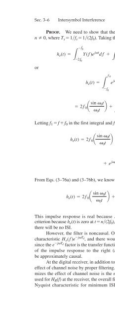
Sec. 3–6 Intersymbol Interference 193 PROOF. We need to show that the impulse response of this filter is 0 at t = nT s , for n Z 0, where T s = 1f s = 1(2f 0 ). Taking the inverse Fourier transform of Eq. (3–75), we have or -f 0 f 0 2f 0 h e (t) = Y(f)e jvt df + [1 + Y(f)]e jvt df + Y(f)e jvt df L -2f 0 L -f 0 L f 0 h e (t) = L f 0 -f 0 e jvt df + L 2f 0 -2f 0 Y(f)e jvt df = 2f 0 a sin v 0 2f 0 0t b + Y(f)e jvt df + Y(f)e jvt df v 0 t L -2f 0 L 0 Letting f 1 = f + f 0 in the first integral and f 1 = f - f 0 in the second integral, we obtain h e (t) = 2f 0 a sin v 0t b + e -jv 0t Y(f 1 - f 0 )e jv1t df 1 v 0 t L-f 0 f 0 + e jv 0t Y(f 1 + f 0 )e jv1t df 1 L-f 0 From Eqs. (3–76a) and (3–76b), we know that Y(f 1 - f 0 ) =-Y(f 1 + f 0 ); thus, we have f 0 h e (t) = 2f 0 a sin v f 0 0t b + j2 sin v v 0 t 0 t Y(f 1 + f 0 )e jv1t df 1 L -f 0 This impulse response is real because H e (-f) = H * e (f), and it satisfies Nyquist’s first criterion because h e (t) is zero at t = n(2f 0 ), n Z 0, and ∆t = 0. Thus, if we sample at t = n(2f 0 ), there will be no ISI. However, the filter is noncausal. Of course, we could use a filter with a linear phase characteristic H e (f)e -jvT d , and there would be no ISI if we delayed the clocking by T d sec, since the e -jvT d factor is the transfer function of an ideal delay line. This would move the peak of the impulse response to the right (along the time axis), and then the filter would be approximately causal. At the digital receiver, in addition to minimizing the ISI, we would like to minimize the effect of channel noise by proper filtering. As will be shown in Chapter 6, the filter that minimizes the effect of channel noise is the matched filter. Unfortunately, if a matched filter is used for H R (f) at the receiver, the overall filter characteristic, H e (f), will usually not satisfy the Nyquist characteristic for minimum ISI. However, it can be shown that for the case of
- Page 382: Sec. 3-5 Line Codes and Spectra 167
- Page 386: Sec. 3-5 Line Codes and Spectra 169
- Page 390: Sec. 3-5 Line Codes and Spectra 171
- Page 394: Sec. 3-5 Line Codes and Spectra 173
- Page 398: Sec. 3-5 Line Codes and Spectra 175
- Page 402: Sec. 3-5 Line Codes and Spectra 177
- Page 406: Sec. 3-5 Line Codes and Spectra 179
- Page 410: Sec. 3-5 Line Codes and Spectra 181
- Page 414: Sec. 3-5 Line Codes and Spectra 183
- Page 418: Sec. 3-6 Intersymbol Interference 1
- Page 422: Sec. 3-6 Intersymbol Interference 1
- Page 426: Sec. 3-6 Intersymbol Interference 1
- Page 430: Sec. 3-6 Intersymbol Interference 1
- Page 436: 194 Baseband Pulse and Digital Sign
- Page 440: 196 DPCM transmitter Analog input s
- Page 444: 198 Baseband Pulse and Digital Sign
- Page 448: 200 Baseband Pulse and Digital Sign
- Page 452: 202 Baseband Pulse and Digital Sign
- Page 456: 204 Baseband Pulse and Digital Sign
- Page 460: 206 Baseband Pulse and Digital Sign
- Page 464: 208 Baseband Pulse and Digital Sign
- Page 468: 210 Baseband Pulse and Digital Sign
- Page 472: 212 Baseband Pulse and Digital Sign
- Page 476: 214 24 DS-0 inputs, 64 kb/s each (1
- Page 480: 216 TABLE 3-9 SPECIFICATIONS FOR T-
Sec. 3–6 Intersymbol Interference 193<br />
PROOF. We need to show that the impulse response of this filter is 0 at t = nT s , for<br />
n Z 0, where T s = 1f s = 1(2f 0 ). Taking the inverse Fourier transform of Eq. (3–75), we have<br />
or<br />
-f 0<br />
f 0<br />
2f 0<br />
h e (t) = Y(f)e jvt df + [1 + Y(f)]e jvt df + Y(f)e jvt df<br />
L -2f 0 L -f 0 L<br />
f 0<br />
h e (t) =<br />
L<br />
f 0<br />
-f 0<br />
e jvt df +<br />
L<br />
2f 0<br />
-2f 0<br />
Y(f)e jvt df<br />
= 2f 0 a sin v 0<br />
2f 0<br />
0t<br />
b + Y(f)e jvt df + Y(f)e jvt df<br />
v 0 t L -2f 0 L 0<br />
Letting f 1 = f + f 0 in the first integral and f 1 = f - f 0 in the second integral, we obtain<br />
h e (t) = 2f 0 a sin v 0t<br />
b + e -jv 0t<br />
Y(f 1 - f 0 )e jv1t df 1<br />
v 0 t<br />
L-f 0<br />
f 0<br />
+ e jv 0t<br />
Y(f 1 + f 0 )e jv1t df 1<br />
L-f 0<br />
From Eqs. (3–76a) and (3–76b), we know that Y(f 1 - f 0 ) =-Y(f 1 + f 0 ); thus, we have<br />
f 0<br />
h e (t) = 2f 0 a sin v f 0<br />
0t<br />
b + j2 sin v<br />
v 0 t<br />
0 t Y(f 1 + f 0 )e jv1t df 1<br />
L -f 0<br />
This impulse response is real because H e (-f) = H<br />
*<br />
e (f), and it satisfies Nyquist’s first<br />
criterion because h e (t) is zero at t = n(2f 0 ), n Z 0, and ∆t = 0. Thus, if we sample at t = n(2f 0 ),<br />
there will be no ISI.<br />
However, the filter is noncausal. Of course, we could use a filter with a linear phase<br />
characteristic H e (f)e -jvT d<br />
, and there would be no ISI if we delayed the clocking by T d sec,<br />
since the e -jvT d<br />
factor is the transfer function of an ideal delay line. This would move the peak<br />
of the impulse response to the right (along the time axis), and then the filter would<br />
be approximately causal.<br />
At the digital receiver, in addition to minimizing the ISI, we would like to minimize the<br />
effect of channel noise by proper filtering. As will be shown in Chapter 6, the filter that minimizes<br />
the effect of channel noise is the matched filter. Unfortunately, if a matched filter is<br />
used for H R (f) at the receiver, the overall filter characteristic, H e (f), will usually not satisfy the<br />
Nyquist characteristic for minimum ISI. However, it can be shown that for the case of


