563489578934
Sec. 3–5 Line Codes and Spectra 165 1 1 BINARY DATA 0 1 0 0 1 (a) Punched Tape Volts A mark (hole) mark (hole) space mark space space (hole) mark (hole) (b) Unipolar NRZ 0 Time A (c) Polar NRZ 0 – A T b A (d) Unipolar RZ 0 A (e) Bipolar RZ 0 – A A (f) Manchester NRZ 0 – A Figure 3–15 Binary signaling formats. Unipolar Signaling. In positive-logic unipolar signaling, the binary 1 is represented by a high level (+A volts) and a binary 0 by a zero level. This type of signaling is also called on–off keying. Polar Signaling. Binary 1’s and 0’s are represented by equal positive and negative levels. Bipolar (Pseudoternary) Signaling. Binary 1’s are represented by alternately positive or negative values. The binary 0 is represented by a zero level. The term pseudoternary refers to the use of three encoded signal levels to represent two-level (binary) data. This is also called alternate mark inversion (AMI) signaling.
- Page 326: Sec. 3-2 Pulse Amplitude Modulation
- Page 330: Sec. 3-3 Pulse Code Modulation 141
- Page 334: PCM transmitter (analog-to-digital
- Page 338: Sec. 3-3 Pulse Code Modulation 145
- Page 342: Sec. 3-3 Pulse Code Modulation 147
- Page 346: Sec. 3-3 Pulse Code Modulation 149
- Page 350: Sec. 3-3 Pulse Code Modulation 151
- Page 354: Sec. 3-3 Pulse Code Modulation 153
- Page 358: Sec. 3-4 Digital Signaling 155 wher
- Page 362: Sec. 3-4 Digital Signaling 157 Eq.
- Page 366: Q Sec. 3-4 Digital Signaling 159 s(
- Page 370: Sec. 3-4 Digital Signaling 161 1.5
- Page 374: Sec. 3-4 Digital Signaling 163 Bina
- Page 380: 166 Baseband Pulse and Digital Sign
- Page 384: 168 Baseband Pulse and Digital Sign
- Page 388: 170 Baseband Pulse and Digital Sign
- Page 392: 172 Baseband Pulse and Digital Sign
- Page 396: 174 Baseband Pulse and Digital Sign
- Page 400: 176 Baseband Pulse and Digital Sign
- Page 404: 178 Baseband Pulse and Digital Sign
- Page 408: 180 Baseband Pulse and Digital Sign
- Page 412: 182 Baseband Pulse and Digital Sign
- Page 416: 184 Baseband Pulse and Digital Sign
- Page 420: 186 Baseband Pulse and Digital Sign
- Page 424: 188 Baseband Pulse and Digital Sign
Sec. 3–5 Line Codes and Spectra 165<br />
1<br />
1<br />
BINARY DATA<br />
0 1 0 0 1<br />
(a) Punched Tape<br />
Volts<br />
A<br />
mark<br />
(hole)<br />
mark<br />
(hole)<br />
space mark space space<br />
(hole)<br />
mark<br />
(hole)<br />
(b) Unipolar NRZ<br />
0<br />
Time<br />
A<br />
(c) Polar NRZ<br />
0<br />
– A<br />
T b<br />
A<br />
(d) Unipolar RZ<br />
0<br />
A<br />
(e) Bipolar RZ<br />
0<br />
– A<br />
A<br />
(f) Manchester NRZ<br />
0<br />
– A<br />
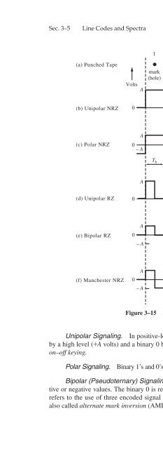
Figure 3–15<br />
Binary signaling formats.<br />
Unipolar Signaling. In positive-logic unipolar signaling, the binary 1 is represented<br />
by a high level (+A volts) and a binary 0 by a zero level. This type of signaling is also called<br />
on–off keying.<br />
Polar Signaling.<br />
Binary 1’s and 0’s are represented by equal positive and negative levels.<br />
Bipolar (Pseudoternary) Signaling. Binary 1’s are represented by alternately positive<br />
or negative values. The binary 0 is represented by a zero level. The term pseudoternary<br />
refers to the use of three encoded signal levels to represent two-level (binary) data. This is<br />
also called alternate mark inversion (AMI) signaling.


