563489578934
Sec. 7–7 Output Signal-to-Noise Ratio for PCM Systems 525 obtained from noisy signals that are present at the receiver input, the reference signals are also noisy. Consequently, the P e will be larger than that given for the ideal case when noise-free sync is assumed. The third type of synchronization that is required by most digital systems is frame sync, or word sync. In some systems, this type of sync is used simply to demark the serial data into digital words or bytes. In other systems, block coding or convolutional coding is used at the transmitter so that some of the bit errors at the output of the threshold device of the receiver can be detected and corrected by using decoding circuits. In these systems, word sync is needed to clock the receiver decoding circuits. In addition, frame sync is required in timedivision multiplex (TDM) systems. This was described in Fig. 3–37. Higher levels of synchronization, such as network synchronization, may be required when data are received from several sources. For example, multiple-access satellite communication systems require network synchronization, as illustrated in Chapter 8. 7–7 OUTPUT SIGNAL-TO-NOISE RATIO FOR PCM SYSTEMS In the previous sections, we studied how the P e for various digital systems depends on the energy per bit E b of the signal at the receiver input and on the level of the input noise spectrum N 0 2. Now we look at applications of these signaling techniques where an analog signal is encoded into a PCM signal composed of the data that are transmitted over the digital system having a BER of P e . This is illustrated in Fig. 7–15. The digital transmitter and receiver may be any one of those associated with the digital signaling systems studied Analog input signal Low-pass filter PCM encoder (analog-to-digital converter) Q(x k ) x k Quantizer Sampler (M levels) Encoder PCM signal (polar waveform) Transmitter s(t) Channel n(t) r(t) Receiver Recovered PCM PCM decoder (digital-to-analog converter) y k =x k +n k Analog sample out (S/N) out measured here Figure 7–15 PCM communications system.
- Page 1046: Sec. 7-2 Performance of Baseband Bi
- Page 1050: Sec. 7-2 Performance of Baseband Bi
- Page 1054: Sec. 7-2 Performance of Baseband Bi
- Page 1058: Sec. 7-3 Coherent Detection of Band
- Page 1062: Sec. 7-3 Coherent Detection of Band
- Page 1066: Sec. 7-3 Coherent Detection of Band
- Page 1070: Sec. 7-4 Noncoherent Detection of B
- Page 1074: Sec. 7-4 Noncoherent Detection of B
- Page 1078: Sec. 7-4 Noncoherent Detection of B
- Page 1082: Sec. 7-4 Noncoherent Detection of B
- Page 1086: Sec. 7-5 Quadrature Phase-Shift Key
- Page 1090: Sec. 7-6 Comparison of Digital Sign
- Page 1094: Sec. 7-6 Comparison of Digital Sign
- Page 1100: 526 Performance of Communication Sy
- Page 1104: 528 Performance of Communication Sy
- Page 1108: 530 Performance of Communication Sy
- Page 1112: 532 Performance of Communication Sy
- Page 1116: 534 Performance of Communication Sy
- Page 1120: 536 Performance of Communication Sy
- Page 1124: 538 Performance of Communication Sy
- Page 1128: 540 Performance of Communication Sy
- Page 1132: 542 Performance of Communication Sy
- Page 1136: 544 Performance of Communication Sy
- Page 1140: 546 Performance of Communication Sy
- Page 1144: 548 Performance of Communication Sy
Sec. 7–7 Output Signal-to-Noise Ratio for PCM Systems 525<br />
obtained from noisy signals that are present at the receiver input, the reference signals are also<br />
noisy. Consequently, the P e will be larger than that given for the ideal case when noise-free<br />
sync is assumed.<br />
The third type of synchronization that is required by most digital systems is frame sync,<br />
or word sync. In some systems, this type of sync is used simply to demark the serial data into<br />
digital words or bytes. In other systems, block coding or convolutional coding is used at the<br />
transmitter so that some of the bit errors at the output of the threshold device of the receiver<br />
can be detected and corrected by using decoding circuits. In these systems, word sync is<br />
needed to clock the receiver decoding circuits. In addition, frame sync is required in timedivision<br />
multiplex (TDM) systems. This was described in Fig. 3–37. Higher levels of<br />
synchronization, such as network synchronization, may be required when data are received<br />
from several sources. For example, multiple-access satellite communication systems require<br />
network synchronization, as illustrated in Chapter 8.<br />
7–7 OUTPUT SIGNAL-TO-NOISE RATIO FOR PCM SYSTEMS<br />
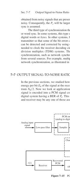
In the previous sections, we studied how the P e for various digital systems depends on the<br />
energy per bit E b of the signal at the receiver input and on the level of the input noise spectrum<br />
N 0 2. Now we look at applications of these signaling techniques where an analog<br />
signal is encoded into a PCM signal composed of the data that are transmitted over the<br />
digital system having a BER of P e . This is illustrated in Fig. 7–15. The digital transmitter<br />
and receiver may be any one of those associated with the digital signaling systems studied<br />
Analog input<br />
signal<br />
Low-pass filter<br />
PCM encoder<br />
(analog-to-digital converter) Q(x k )<br />
x k Quantizer<br />
Sampler<br />
(M levels)<br />
Encoder<br />
PCM signal<br />
(polar waveform)<br />
Transmitter<br />
s(t)<br />
Channel<br />
n(t)<br />
<br />
r(t)<br />
Receiver<br />
Recovered<br />
PCM<br />
PCM decoder<br />
(digital-to-analog converter)<br />
y k =x k +n k<br />
Analog sample out<br />
(S/N) out measured here<br />
Figure 7–15<br />
PCM communications system.


