4569846498
Kinematics and dynamics of rigid bodies 59 ∫ 2 2 ) Izz ( x y d m In addition we can introduce the products of inertia I xy , I yz and I xz : (2.172) Ixy Iyx ∫ xy dm Iyz Izy ∫ yz d m Ixz Izx ∫ xz d m (2.173) (2.174) (2.175) This allows (2.167) to (2.169) to be arranged in matrix form as follows: ⎡Hx ⎤ ⎡Ixx Ixy Ixz ⎤ ⎡ x ⎤ ⎢ H ⎥ ⎢ ⎥ (2.176) ⎢ y ⎥ I I I ⎢ ⎢ xy yy yz ⎥ ⎢ ⎥ y ⎥ ⎣⎢ Hz ⎦⎥ ⎢I I I ⎥ ⎣ xz yz zz ⎦ ⎣⎢ z ⎦⎥ If we return to our earlier consideration of Body 2 shown in Figure 2.27 the matrix equation in (2.176) would lead to {H 2 } 1/1 [I 2 ] 2/1 { 2 } 1/1 (2.177) In writing the vectors {H 2 } 1/1 { 2 } 1/1 we revert to the full definition of a vector used here where the upper suffix indicates that the vector is measured relative to the axes of reference frame O 1 and the lower suffix indicates that the components of the vector are resolved parallel to the axes of frame O 1 . The matrix [I 2 ] 2/1 is the moment of inertia matrix for Body 2 about its mass centre G 2 located at frame O 2 . The use of the upper and lower suffix here indicates that the moments of inertia have been measured relative to frame O 2 but transformed to frame O 1 . This is necessary so that the vector operation in (2.177) is consistent. This is only possible if the vectors and matrix are referred to the same frame, which in this case is O 1 . Note that in this form (2.177) is not practical since the orientation of frame O 2 relative to frame O 1 will change as the body rotates requiring the recomputation of [I 2 ] 2/1 at each time step. The matrix [I 2 ] 2/2, or in simpler form [I 2 ] 2 , is constant since it is measured relative to and referred to a frame that is fixed in Body 2 and hence only needs to be determined once for an undeformable body. When considering the equation for the angular momentum of a body it is preferable therefore to consider all quantities to be referred to a frame fixed in the body, in this case frame O 2 : {H 2 } 1/2 [I 2 ] 2/2 { 2 } 1/2 (2.178) Before progressing to develop the equations used to describe the dynamics of rigid bodies translating and rotating in three-dimensional space the definition of the moments of inertia introduced here requires further consideration. 2.10 Moments of inertia From our previous consideration of the angular momentum of a rigid body we see that there are three moments of inertia and three products of inertia
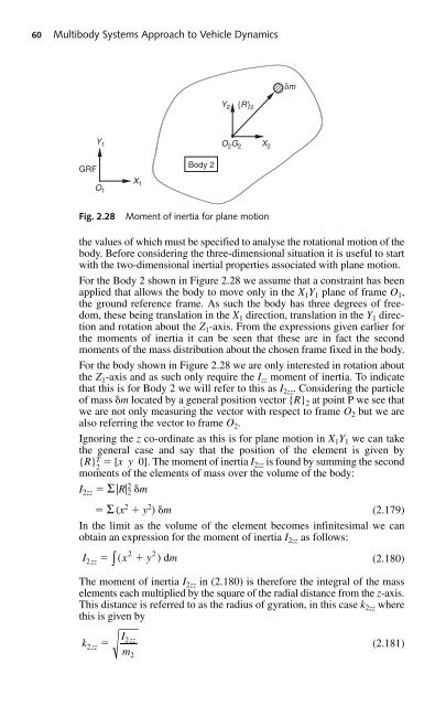
60 Multibody Systems Approach to Vehicle Dynamics δm Y 2 {R} 2 Y 1 Body 2 O 2 G 2 X 2 GRF O 1 X 1 Fig. 2.28 Moment of inertia for plane motion the values of which must be specified to analyse the rotational motion of the body. Before considering the three-dimensional situation it is useful to start with the two-dimensional inertial properties associated with plane motion. For the Body 2 shown in Figure 2.28 we assume that a constraint has been applied that allows the body to move only in the X 1 Y 1 plane of frame O 1 , the ground reference frame. As such the body has three degrees of freedom, these being translation in the X 1 direction, translation in the Y 1 direction and rotation about the Z 1 -axis. From the expressions given earlier for the moments of inertia it can be seen that these are in fact the second moments of the mass distribution about the chosen frame fixed in the body. For the body shown in Figure 2.28 we are only interested in rotation about the Z 1 -axis and as such only require the I zz moment of inertia. To indicate that this is for Body 2 we will refer to this as I 2zz . Considering the particle of mass m located by a general position vector {R} 2 at point P we see that we are not only measuring the vector with respect to frame O 2 but we are also referring the vector to frame O 2 . Ignoring the z co-ordinate as this is for plane motion in X 1 Y 1 we can take the general case and say that the position of the element is given by {R} T 2 [x y0]. The moment of inertia I 2zz is found by summing the second moments of the elements of mass over the volume of the body: I 2zz Σ |R| 2 2 m Σ (x 2 y 2 ) m (2.179) In the limit as the volume of the element becomes infinitesimal we can obtain an expression for the moment of inertia I 2zz as follows: I ( x y ) dm (2.180) The moment of inertia I 2zz in (2.180) is therefore the integral of the mass elements each multiplied by the square of the radial distance from the z-axis. This distance is referred to as the radius of gyration, in this case k 2zz where this is given by k 2zz 2zz ∫ 2 I2 m zz 2 2 (2.181)
- Page 32 and 33: Introduction 9 3. The body yaws (ro
- Page 34 and 35: Introduction 11 Aspiration Definiti
- Page 36 and 37: Introduction 13 Decomposition: Synt
- Page 38 and 39: Introduction 15 The best multibody
- Page 40 and 41: Introduction 17 shows good correlat
- Page 42 and 43: Introduction 19 generated in numeri
- Page 44 and 45: Introduction 21 1.9 Benchmarking ex
- Page 46 and 47: 2 Kinematics and dynamics of rigid
- Page 48 and 49: Kinematics and dynamics of rigid bo
- Page 50 and 51: Kinematics and dynamics of rigid bo
- Page 52 and 53: Kinematics and dynamics of rigid bo
- Page 54 and 55: Kinematics and dynamics of rigid bo
- Page 56 and 57: Kinematics and dynamics of rigid bo
- Page 58 and 59: Kinematics and dynamics of rigid bo
- Page 60 and 61: Kinematics and dynamics of rigid bo
- Page 62 and 63: Kinematics and dynamics of rigid bo
- Page 64 and 65: Kinematics and dynamics of rigid bo
- Page 66 and 67: Kinematics and dynamics of rigid bo
- Page 68 and 69: Kinematics and dynamics of rigid bo
- Page 70 and 71: Kinematics and dynamics of rigid bo
- Page 72 and 73: Kinematics and dynamics of rigid bo
- Page 74 and 75: Kinematics and dynamics of rigid bo
- Page 76 and 77: Kinematics and dynamics of rigid bo
- Page 78 and 79: Kinematics and dynamics of rigid bo
- Page 80 and 81: Kinematics and dynamics of rigid bo
- Page 84 and 85: Kinematics and dynamics of rigid bo
- Page 86 and 87: Kinematics and dynamics of rigid bo
- Page 88 and 89: Kinematics and dynamics of rigid bo
- Page 90 and 91: Kinematics and dynamics of rigid bo
- Page 92 and 93: Kinematics and dynamics of rigid bo
- Page 94 and 95: Kinematics and dynamics of rigid bo
- Page 96 and 97: Kinematics and dynamics of rigid bo
- Page 98 and 99: 3 Multibody systems simulation soft
- Page 100 and 101: Multibody systems simulation softwa
- Page 102 and 103: Multibody systems simulation softwa
- Page 104 and 105: Multibody systems simulation softwa
- Page 106 and 107: Multibody systems simulation softwa
- Page 108 and 109: Multibody systems simulation softwa
- Page 110 and 111: Multibody systems simulation softwa
- Page 112 and 113: Multibody systems simulation softwa
- Page 114 and 115: Multibody systems simulation softwa
- Page 116 and 117: Multibody systems simulation softwa
- Page 118 and 119: Multibody systems simulation softwa
- Page 120 and 121: Multibody systems simulation softwa
- Page 122 and 123: Multibody systems simulation softwa
- Page 124 and 125: Multibody systems simulation softwa
- Page 126 and 127: Multibody systems simulation softwa
- Page 128 and 129: Multibody systems simulation softwa
- Page 130 and 131: Multibody systems simulation softwa
60 Multibody Systems Approach to Vehicle Dynamics<br />
δm<br />
Y 2<br />
{R} 2<br />
Y 1<br />
Body 2<br />
O 2 G 2<br />
X 2<br />
GRF<br />
O 1<br />
X 1<br />
Fig. 2.28<br />
Moment of inertia for plane motion<br />
the values of which must be specified to analyse the rotational motion of the<br />
body. Before considering the three-dimensional situation it is useful to start<br />
with the two-dimensional inertial properties associated with plane motion.<br />
For the Body 2 shown in Figure 2.28 we assume that a constraint has been<br />
applied that allows the body to move only in the X 1 Y 1 plane of frame O 1 ,<br />
the ground reference frame. As such the body has three degrees of freedom,<br />
these being translation in the X 1 direction, translation in the Y 1 direction<br />
and rotation about the Z 1 -axis. From the expressions given earlier for<br />
the moments of inertia it can be seen that these are in fact the second<br />
moments of the mass distribution about the chosen frame fixed in the body.<br />
For the body shown in Figure 2.28 we are only interested in rotation about<br />
the Z 1 -axis and as such only require the I zz moment of inertia. To indicate<br />
that this is for Body 2 we will refer to this as I 2zz . Considering the particle<br />
of mass m located by a general position vector {R} 2 at point P we see that<br />
we are not only measuring the vector with respect to frame O 2 but we are<br />
also referring the vector to frame O 2 .<br />
Ignoring the z co-ordinate as this is for plane motion in X 1 Y 1 we can take<br />
the general case and say that the position of the element is given by<br />
{R} T 2 [x y0]. The moment of inertia I 2zz is found by summing the second<br />
moments of the elements of mass over the volume of the body:<br />
I 2zz Σ |R| 2 2 m<br />
Σ (x 2 y 2 ) m (2.179)<br />
In the limit as the volume of the element becomes infinitesimal we can<br />
obtain an expression for the moment of inertia I 2zz as follows:<br />
I ( x y ) dm<br />
(2.180)<br />
The moment of inertia I 2zz in (2.180) is therefore the integral of the mass<br />
elements each multiplied by the square of the radial distance from the z-axis.<br />
This distance is referred to as the radius of gyration, in this case k 2zz where<br />
this is given by<br />
k<br />
2zz<br />
2zz<br />
<br />
∫<br />
2<br />
I2<br />
m<br />
zz<br />
2<br />
2<br />
(2.181)


