4569846498
Simulation output and interpretation 399 the difference actually observed in the test. In other words, differences of less than 0.08g cannot be controlled reliably using such a measurement process. However, such a difference is a significant one between otherwise similar vehicles, representing something around 10% of the total lateral acceleration available. While the dataset shown in the example is fictitious, the statistical character of the measurements is entirely typical, even under well-controlled conditions. When a vehicle is nearly optimized, this problem is typical. The resolution of the process in use – the test facilities and so on – is comparable to or greater than the control required to optimize the vehicle further. For this reason, in both motorsport and production vehicle engineering, a great deal of the final optimization is based on subjective judgements of a few well-chosen individuals. 7.3 A vehicle dynamics overview 7.3.1 Travel on a curved path At this point, it is appropriate to develop some basic notions about vehicle dynamics. These definitions will be used later to suggest an interpretation of the subjective/objective relationship; however, it should be clear that by its very nature the absolute quantification of subjective qualities is impossible. The driver has two primary concerns in controlling the vehicle. These are speed and path. Speed is controlled with engine power and braking systems. The use of separate controls for acceleration and deceleration is logical when the systems are separate but may become less so if vehicle architecture changes significantly; for example, some system with a ‘motor in each wheel’ that both accelerates and brakes might have a single pedal for control, of the type prototyped by Nomix AB in Sweden (http://www.nomix.se/ nomixl.html) and under investigation by the Swedish National Road Administration at the time of writing. Variation of speed is governed by vehicle mass and tractive/brake power availability at all but the lowest speed, and is easily understood. The adjustment of path curvature at a given speed is altogether more interesting. In a passenger car the driver has a handwheel, viewed by the authors as a ‘yaw rate’ demand – a demand for rotational velocity of the vehicle when viewed from above. The combination of a yaw rate and a forward velocity vector, which rotates with the vehicle, gives rise to a curved path. The curved path of the vehicle requires some lateral acceleration. The tyres on a car exert a force towards the centre of a turn and the body mass is accelerated by those forces centripetally – in a curved path. Thus the sum of the lateral forces that the tyres exert on the car is the centripetal force that produces the centripetal acceleration (Figure 7.3). Note that the authors do not favour the use of the equivalent inertial (‘D’Alembert’) force since it can be misleading; it gives the impression that the analysis of the cornering vehicle is a static equilibrium problem, which it most certainly is not. The idea of an analogous static equilibrium condition is not in itself problematic but inappropriate ‘static’ thinking quickly becomes torturous and unwieldy. For example, a common obsession is to attempt to
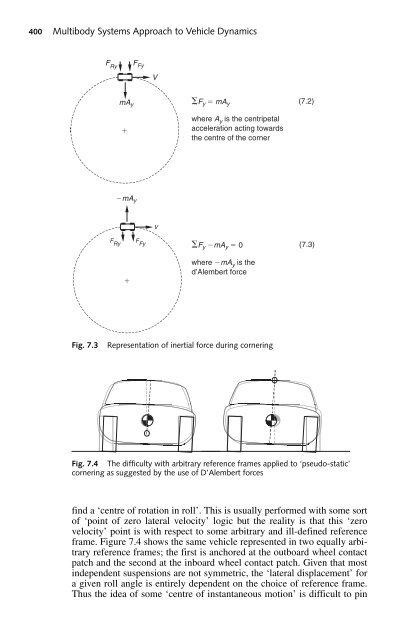
400 Multibody Systems Approach to Vehicle Dynamics V F Ry F Fy mA F y mA y y where A y is the centripetal acceleration acting towards the centre of the corner mA y V F Ry F Fy F y mA y 0 (7.2) (7.3) where mA y is the d’Alembert force Fig. 7.3 Representation of inertial force during cornering Fig. 7.4 The difficulty with arbitrary reference frames applied to ‘pseudo-static’ cornering as suggested by the use of D’Alembert forces find a ‘centre of rotation in roll’. This is usually performed with some sort of ‘point of zero lateral velocity’ logic but the reality is that this ‘zero velocity’ point is with respect to some arbitrary and ill-defined reference frame. Figure 7.4 shows the same vehicle represented in two equally arbitrary reference frames; the first is anchored at the outboard wheel contact patch and the second at the inboard wheel contact patch. Given that most independent suspensions are not symmetric, the ‘lateral displacement’ for a given roll angle is entirely dependent on the choice of reference frame. Thus the idea of some ‘centre of instantaneous motion’ is difficult to pin
- Page 372 and 373: Modelling and assembly of the full
- Page 374 and 375: Modelling and assembly of the full
- Page 376 and 377: Modelling and assembly of the full
- Page 378 and 379: Modelling and assembly of the full
- Page 380 and 381: Modelling and assembly of the full
- Page 382 and 383: Modelling and assembly of the full
- Page 384 and 385: Modelling and assembly of the full
- Page 386 and 387: Modelling and assembly of the full
- Page 388 and 389: Modelling and assembly of the full
- Page 390 and 391: Modelling and assembly of the full
- Page 392 and 393: Modelling and assembly of the full
- Page 394 and 395: Modelling and assembly of the full
- Page 396 and 397: Modelling and assembly of the full
- Page 398 and 399: Modelling and assembly of the full
- Page 400 and 401: Modelling and assembly of the full
- Page 402 and 403: Modelling and assembly of the full
- Page 404 and 405: Modelling and assembly of the full
- Page 406 and 407: Modelling and assembly of the full
- Page 408 and 409: Modelling and assembly of the full
- Page 410 and 411: Modelling and assembly of the full
- Page 412 and 413: Modelling and assembly of the full
- Page 414 and 415: Modelling and assembly of the full
- Page 416 and 417: Modelling and assembly of the full
- Page 418 and 419: 7 Simulation output and interpretat
- Page 420 and 421: Simulation output and interpretatio
- Page 424 and 425: down and even more difficult to asc
- Page 426 and 427: Simulation output and interpretatio
- Page 428 and 429: Simulation output and interpretatio
- Page 430 and 431: Simulation output and interpretatio
- Page 432 and 433: Simulation output and interpretatio
- Page 434 and 435: Simulation output and interpretatio
- Page 436 and 437: Simulation output and interpretatio
- Page 438 and 439: Simulation output and interpretatio
- Page 440 and 441: Simulation output and interpretatio
- Page 442 and 443: Simulation output and interpretatio
- Page 444 and 445: Simulation output and interpretatio
- Page 446 and 447: Simulation output and interpretatio
- Page 448 and 449: Simulation output and interpretatio
- Page 450 and 451: Simulation output and interpretatio
- Page 452 and 453: Simulation output and interpretatio
- Page 454 and 455: Simulation output and interpretatio
- Page 456 and 457: Simulation output and interpretatio
- Page 458 and 459: Simulation output and interpretatio
- Page 460 and 461: Simulation output and interpretatio
- Page 462 and 463: Simulation output and interpretatio
- Page 464 and 465: 8 Active systems 8.1 Introduction M
- Page 466 and 467: Active systems 443 mechanical actua
- Page 468 and 469: Active systems 445 Table 8.1 MSC.AD
- Page 470 and 471: Active systems 447 Body acceleratio
400 Multibody Systems Approach to Vehicle Dynamics<br />
V<br />
F Ry F Fy<br />
mA F y mA y<br />
y<br />
where A y is the centripetal<br />
<br />
acceleration acting towards<br />
the centre of the corner<br />
mA y<br />
V<br />
F Ry<br />
F Fy F y mA y 0<br />
(7.2)<br />
(7.3)<br />
<br />
where mA y is the<br />
d’Alembert force<br />
Fig. 7.3<br />
Representation of inertial force during cornering<br />
Fig. 7.4 The difficulty with arbitrary reference frames applied to ‘pseudo-static’<br />
cornering as suggested by the use of D’Alembert forces<br />
find a ‘centre of rotation in roll’. This is usually performed with some sort<br />
of ‘point of zero lateral velocity’ logic but the reality is that this ‘zero<br />
velocity’ point is with respect to some arbitrary and ill-defined reference<br />
frame. Figure 7.4 shows the same vehicle represented in two equally arbitrary<br />
reference frames; the first is anchored at the outboard wheel contact<br />
patch and the second at the inboard wheel contact patch. Given that most<br />
independent suspensions are not symmetric, the ‘lateral displacement’ for<br />
a given roll angle is entirely dependent on the choice of reference frame.<br />
Thus the idea of some ‘centre of instantaneous motion’ is difficult to pin


