4569846498
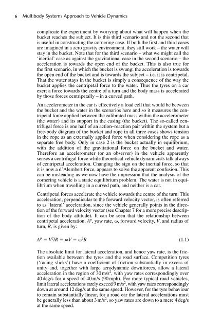
Introduction 5 Fig. 1.4 Linearity: more handwheel input results in proportionally more yaw rate (vehicle on left) 2 1 3 Fig. 1.5 A thought experiment comparing centripetal acceleration with linear acceleration acceleration – ‘centre seeking’. Note that speed is not the same as velocity; travelling in a curved path with a constant speed implies a changing direction and therefore a changing velocity. The centripetal acceleration definition causes some problems since everyone ‘knows’ that they are flung to the outside of a car if unrestrained and so there is much lax talk of centrifugal forces – ‘centre fleeing’. To clarify this issue, a brief thought experiment is required (Figure 1.5). Imagine a bucket of water on a rope being swung around by a subject. If the subject looks at the bucket then the water is apparently pressed into the bucket by the mythical ‘centrifugal force’ (presuming the bucket is being swung fast enough). If the swinging is halted and the bucket simply suspended by the rope then the water is held in the bucket by the downward gravitational field of the earth – the weight of the water pulls it into the bucket. Imagine now a different scenario in which the bucket (on a frictionless plane) is pulled horizontally towards the observer at a constant acceleration in a linear fashion. It’s best not to
6 Multibody Systems Approach to Vehicle Dynamics complicate the experiment by worrying about what will happen when the bucket reaches the subject. It is this third scenario and not the second that is useful in constructing the cornering case. If both the first and third cases are imagined in a zero gravity environment, they still work – the water will stay in the bucket. Note that for the third scenario – what we might call the ‘inertial’ case as against the gravitational case in the second scenario – the acceleration is towards the open end of the bucket. This is also true for the first scenario, in which the bucket is swung; the acceleration is towards the open end of the bucket and is towards the subject – i.e. it is centripetal. That the water stays in the bucket is simply a consequence of the way the bucket applies the centripetal force to the water. Thus the tyres on a car exert a force towards the centre of a turn and the body mass is accelerated by those forces centripetally – in a curved path. An accelerometer in the car is effectively a load cell that would be between the bucket and the water in the scenarios here and so it measures the centripetal force applied between the calibrated mass within the accelerometer (the water) and its support in the casing (the bucket). The so-called centrifugal force is one half of an action–reaction pair within the system but a free-body diagram of the bucket and rope in all three cases shows tension in the rope as an externally applied force when considering the rope as a separate free body. Only in case 2 is the bucket actually in equilibrium, with the addition of the gravitational force on the bucket and water. Therefore an accelerometer (or an observer) in the vehicle apparently senses a centrifugal force while theoretical vehicle dynamicists talk always of centripetal acceleration. Changing the sign on the inertial force, so that it is now a d’Alembert force, appears to solve the apparent confusion. This can be misleading as we now have the impression that the analysis of the cornering vehicle is a static equilibrium problem. The water is not in equilibrium when travelling in a curved path, and neither is a car. Centripetal forces accelerate the vehicle towards the centre of the turn. This acceleration, perpendicular to the forward velocity vector, is often referred to as ‘lateral’ acceleration, since the vehicle generally points in the direction of the forward velocity vector (see Chapter 7 for a more precise description of the body attitude). It can be seen that the relationship between centripetal acceleration, A p , yaw rate, , forward velocity, V, and radius of turn, R, is given by: A p V 2 /R V 2 R (1.1) The absolute limit for lateral acceleration, and hence yaw rate, is the friction available between the tyres and the road surface. Competition tyres (‘racing slicks’) have a coefficient of friction substantially in excess of unity and, together with large aerodynamic downforces, allow a lateral acceleration in the region of 30 m/s 2 , with yaw rates correspondingly over 40 deg/s for a speed of 40 m/s (90 mph). For more typical road vehicles, limit lateral accelerations rarely exceed 9 m/s 2 , with yaw rates correspondingly down at around 12 deg/s at the same speed. However, for the tyre behaviour to remain substantially linear, for a road car the lateral accelerations must be generally less than about 3 m/s 2 , so yaw rates are down to a mere 4 deg/s at the same speed.
- Page 2 and 3: Multibody Systems Approach to Vehic
- Page 4 and 5: Multibody Systems Approach to Vehic
- Page 6 and 7: Contents Preface Acknowledgements N
- Page 8 and 9: Contents vii 4.10.1 Problem definit
- Page 10 and 11: Contents ix 8.2.1 Active suspension
- Page 12 and 13: Preface This book is intended to br
- Page 14 and 15: Preface xiii vehicle design process
- Page 16 and 17: Acknowledgements Mike Blundell In d
- Page 18 and 19: Nomenclature xvii {z I } 1 Unit vec
- Page 20 and 21: Nomenclature xix O n Frame for part
- Page 22 and 23: Nomenclature xxi p Magnitude of re
- Page 24 and 25: 1 Introduction The most cost-effect
- Page 26 and 27: Introduction 3 subsequent ‘classi
- Page 30 and 31: Introduction 7 While apparently a s
- Page 32 and 33: Introduction 9 3. The body yaws (ro
- Page 34 and 35: Introduction 11 Aspiration Definiti
- Page 36 and 37: Introduction 13 Decomposition: Synt
- Page 38 and 39: Introduction 15 The best multibody
- Page 40 and 41: Introduction 17 shows good correlat
- Page 42 and 43: Introduction 19 generated in numeri
- Page 44 and 45: Introduction 21 1.9 Benchmarking ex
- Page 46 and 47: 2 Kinematics and dynamics of rigid
- Page 48 and 49: Kinematics and dynamics of rigid bo
- Page 50 and 51: Kinematics and dynamics of rigid bo
- Page 52 and 53: Kinematics and dynamics of rigid bo
- Page 54 and 55: Kinematics and dynamics of rigid bo
- Page 56 and 57: Kinematics and dynamics of rigid bo
- Page 58 and 59: Kinematics and dynamics of rigid bo
- Page 60 and 61: Kinematics and dynamics of rigid bo
- Page 62 and 63: Kinematics and dynamics of rigid bo
- Page 64 and 65: Kinematics and dynamics of rigid bo
- Page 66 and 67: Kinematics and dynamics of rigid bo
- Page 68 and 69: Kinematics and dynamics of rigid bo
- Page 70 and 71: Kinematics and dynamics of rigid bo
- Page 72 and 73: Kinematics and dynamics of rigid bo
- Page 74 and 75: Kinematics and dynamics of rigid bo
- Page 76 and 77: Kinematics and dynamics of rigid bo
6 Multibody Systems Approach to Vehicle Dynamics<br />
complicate the experiment by worrying about what will happen when the<br />
bucket reaches the subject. It is this third scenario and not the second that<br />
is useful in constructing the cornering case. If both the first and third cases<br />
are imagined in a zero gravity environment, they still work – the water will<br />
stay in the bucket. Note that for the third scenario – what we might call the<br />
‘inertial’ case as against the gravitational case in the second scenario – the<br />
acceleration is towards the open end of the bucket. This is also true for<br />
the first scenario, in which the bucket is swung; the acceleration is towards<br />
the open end of the bucket and is towards the subject – i.e. it is centripetal.<br />
That the water stays in the bucket is simply a consequence of the way the<br />
bucket applies the centripetal force to the water. Thus the tyres on a car<br />
exert a force towards the centre of a turn and the body mass is accelerated<br />
by those forces centripetally – in a curved path.<br />
An accelerometer in the car is effectively a load cell that would be between<br />
the bucket and the water in the scenarios here and so it measures the centripetal<br />
force applied between the calibrated mass within the accelerometer<br />
(the water) and its support in the casing (the bucket). The so-called centrifugal<br />
force is one half of an action–reaction pair within the system but a<br />
free-body diagram of the bucket and rope in all three cases shows tension<br />
in the rope as an externally applied force when considering the rope as a<br />
separate free body. Only in case 2 is the bucket actually in equilibrium,<br />
with the addition of the gravitational force on the bucket and water.<br />
Therefore an accelerometer (or an observer) in the vehicle apparently<br />
senses a centrifugal force while theoretical vehicle dynamicists talk always<br />
of centripetal acceleration. Changing the sign on the inertial force, so that<br />
it is now a d’Alembert force, appears to solve the apparent confusion. This<br />
can be misleading as we now have the impression that the analysis of the<br />
cornering vehicle is a static equilibrium problem. The water is not in equilibrium<br />
when travelling in a curved path, and neither is a car.<br />
Centripetal forces accelerate the vehicle towards the centre of the turn. This<br />
acceleration, perpendicular to the forward velocity vector, is often referred<br />
to as ‘lateral’ acceleration, since the vehicle generally points in the direction<br />
of the forward velocity vector (see Chapter 7 for a more precise description<br />
of the body attitude). It can be seen that the relationship between<br />
centripetal acceleration, A p , yaw rate, , forward velocity, V, and radius of<br />
turn, R, is given by:<br />
A p V 2 /R V 2 R (1.1)<br />
The absolute limit for lateral acceleration, and hence yaw rate, is the friction<br />
available between the tyres and the road surface. Competition tyres<br />
(‘racing slicks’) have a coefficient of friction substantially in excess of<br />
unity and, together with large aerodynamic downforces, allow a lateral<br />
acceleration in the region of 30 m/s 2 , with yaw rates correspondingly over<br />
40 deg/s for a speed of 40 m/s (90 mph). For more typical road vehicles,<br />
limit lateral accelerations rarely exceed 9 m/s 2 , with yaw rates correspondingly<br />
down at around 12 deg/s at the same speed. However, for the tyre behaviour<br />
to remain substantially linear, for a road car the lateral accelerations must<br />
be generally less than about 3 m/s 2 , so yaw rates are down to a mere 4 deg/s<br />
at the same speed.


