4569846498
Tyre characteristics and modelling 249 understanding of these force and moment characteristics is essential before introducing the various mathematical tyre models available and describing the methods used to implement these with MBS vehicle models. Before a computer simulation can be performed the tyre force and moment characteristics must be estimated or obtained from experimental tests. A traditional approach is to test the tyre using a tyre test machine and to measure the resulting force and moment components for various camber angles, slip angles and values of vertical force. The measured data is set up in tabular form, which is interpolated during the computer simulation in order to transfer the forces to the full vehicle model. Alternatively mathematical functions are used to fit equations to the measured test data. These equations provide a mathematical tyre model that can be incorporated into the full vehicle model. This method requires the generation of a number of parameters that must be derived from the measured data before the simulation can proceed. The quality of the model will be a compromise between the accuracy of the fit, relevance of the parameters, and the availability of methods to generate the parameters. 5.2 Tyre axis systems and geometry 5.2.1 The SAE and ISO tyre axis systems To assist with the description of the forces and moments generated by a tyre, an axis system shown in simplified form in Figure 5.2 has been defined by the SAE (1976). In this system the X-axis is the intersection of the wheel plane and the road plane with the positive direction taken for the wheel moving forward. The Z-axis is perpendicular to the road plane with a positive direction assumed to be acting downwards. The Y-axis is in the road plane, its direction dictated by the use of a right-handed orthogonal axis system. The angles and represent the slip angle and camber angle respectively. The SAE system will be used throughout this text unless stated. It should be noted that not all practitioners adhere rigidly to this system in their publications and another system, the ISO tyre system, is gaining favour. This system, shown simplified in Figure 5.3, is likely to become the standard for future tyre models. It will be seen later that distortions in the tyre carcass will cause the contact patch to move away from the rigid wheel plane shown in Figures 5.2 and 5.3. Although the components of force are still assumed to act through the contact point P the distortions will introduce offsets and additional components of moment also acting about the point P. 5.2.2 Definition of tyre radii The definition of tyre radii is important for the formulation of slip in the contact patch. In general we consider a tyre to have an unloaded radius, a loaded radius and an effective rolling radius. The unloaded tyre radius, R u , is straightforward to comprehend and is shown in Figure 5.4. For a rigid disc with radius R u rolling forward with no sliding (fully geared to the road), during one revolution the disc will move forward a distance 2R u .
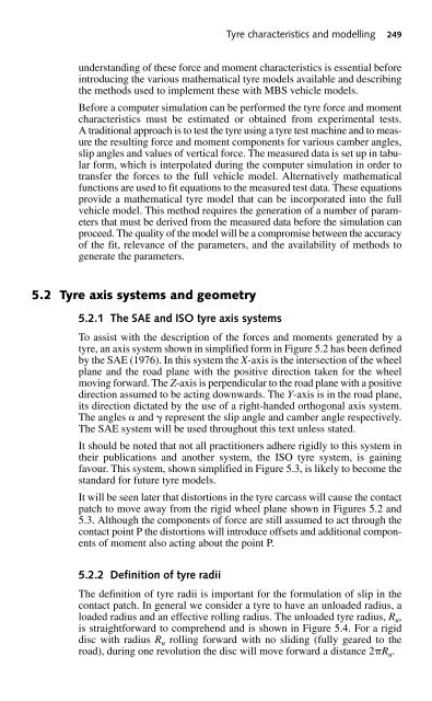
250 Multibody Systems Approach to Vehicle Dynamics ANGULAR VELOCITY () WHEEL TORQUE (T ) SPIN AXIS WC DIRECTION OF WHEEL HEADING {X SAE } 1 TRACTIVE FORCE (F x ) {V } 1 P DIRECTION OF WHEEL TRAVEL NORMAL FORCE (F z ) {Z SAE } 1 {Y SAE } 1 LATERAL FORCE (F y ) Fig. 5.2 SAE tyre axis system Normal force (F z ) {Z ISO } 1 Angular velocity () wheel torque (T ) Spin axis Direction of wheel heading Lateral force (F y ) Fig. 5.3 {X {Y ISO } ISO } 1 Tractive 1 WC force (F x ) ISO tyre axis system P Direction of wheel travel As can be seen from Figure 5.4, due to tyre deflection the distance moved forward will be less than for the rigid disc and can be related to the effective rolling radius giving R u R e R l (5.1) Another definition of effective rolling radius is provided by Moore (1975), this being the distance from the wheel centre to a point C where the distance AC is taken to be one quarter of the total tyre contact patch length AB. The following are other definitions related to tyre radius provided in SAE J670e (SAE Publication, 1976): (i) The loaded radius, R l , is the distance from the centre of the tyre contact patch to the wheel centre measured in the wheel plane. {V } 1
- Page 222 and 223: Modelling and analysis of suspensio
- Page 224 and 225: Modelling and analysis of suspensio
- Page 226 and 227: Modelling and analysis of suspensio
- Page 228 and 229: Modelling and analysis of suspensio
- Page 230 and 231: Modelling and analysis of suspensio
- Page 232 and 233: Modelling and analysis of suspensio
- Page 234 and 235: Modelling and analysis of suspensio
- Page 236 and 237: Modelling and analysis of suspensio
- Page 238 and 239: Modelling and analysis of suspensio
- Page 240 and 241: Modelling and analysis of suspensio
- Page 242 and 243: Modelling and analysis of suspensio
- Page 244 and 245: Modelling and analysis of suspensio
- Page 246 and 247: Modelling and analysis of suspensio
- Page 248 and 249: Modelling and analysis of suspensio
- Page 250 and 251: Modelling and analysis of suspensio
- Page 252 and 253: Modelling and analysis of suspensio
- Page 254 and 255: Modelling and analysis of suspensio
- Page 256 and 257: Modelling and analysis of suspensio
- Page 258 and 259: Modelling and analysis of suspensio
- Page 260 and 261: Modelling and analysis of suspensio
- Page 262 and 263: Modelling and analysis of suspensio
- Page 264 and 265: Modelling and analysis of suspensio
- Page 266 and 267: Modelling and analysis of suspensio
- Page 268 and 269: Modelling and analysis of suspensio
- Page 270 and 271: Modelling and analysis of suspensio
- Page 274 and 275: Tyre characteristics and modelling
- Page 276 and 277: Tyre characteristics and modelling
- Page 278 and 279: Tyre characteristics and modelling
- Page 280 and 281: Tyre characteristics and modelling
- Page 282 and 283: Tyre characteristics and modelling
- Page 284 and 285: Tyre characteristics and modelling
- Page 286 and 287: Tyre characteristics and modelling
- Page 288 and 289: Tyre characteristics and modelling
- Page 290 and 291: Tyre characteristics and modelling
- Page 292 and 293: Tyre characteristics and modelling
- Page 294 and 295: Tyre characteristics and modelling
- Page 296 and 297: Tyre characteristics and modelling
- Page 298 and 299: Tyre characteristics and modelling
- Page 300 and 301: Tyre characteristics and modelling
- Page 302 and 303: Tyre characteristics and modelling
- Page 304 and 305: Tyre characteristics and modelling
- Page 306 and 307: Tyre characteristics and modelling
- Page 308 and 309: Tyre characteristics and modelling
- Page 310 and 311: Tyre characteristics and modelling
- Page 312 and 313: Tyre characteristics and modelling
- Page 314 and 315: Tyre characteristics and modelling
- Page 316 and 317: Tyre characteristics and modelling
- Page 318 and 319: Tyre characteristics and modelling
- Page 320 and 321: Tyre characteristics and modelling
Tyre characteristics and modelling 249<br />
understanding of these force and moment characteristics is essential before<br />
introducing the various mathematical tyre models available and describing<br />
the methods used to implement these with MBS vehicle models.<br />
Before a computer simulation can be performed the tyre force and moment<br />
characteristics must be estimated or obtained from experimental tests.<br />
A traditional approach is to test the tyre using a tyre test machine and to measure<br />
the resulting force and moment components for various camber angles,<br />
slip angles and values of vertical force. The measured data is set up in tabular<br />
form, which is interpolated during the computer simulation in order to<br />
transfer the forces to the full vehicle model. Alternatively mathematical<br />
functions are used to fit equations to the measured test data. These equations<br />
provide a mathematical tyre model that can be incorporated into the full<br />
vehicle model. This method requires the generation of a number of parameters<br />
that must be derived from the measured data before the simulation can<br />
proceed. The quality of the model will be a compromise between the accuracy<br />
of the fit, relevance of the parameters, and the availability of methods to<br />
generate the parameters.<br />
5.2 Tyre axis systems and geometry<br />
5.2.1 The SAE and ISO tyre axis systems<br />
To assist with the description of the forces and moments generated by a<br />
tyre, an axis system shown in simplified form in Figure 5.2 has been defined<br />
by the SAE (1976). In this system the X-axis is the intersection of the wheel<br />
plane and the road plane with the positive direction taken for the wheel<br />
moving forward. The Z-axis is perpendicular to the road plane with a positive<br />
direction assumed to be acting downwards. The Y-axis is in the road plane,<br />
its direction dictated by the use of a right-handed orthogonal axis system.<br />
The angles and represent the slip angle and camber angle respectively.<br />
The SAE system will be used throughout this text unless stated.<br />
It should be noted that not all practitioners adhere rigidly to this system in<br />
their publications and another system, the ISO tyre system, is gaining<br />
favour. This system, shown simplified in Figure 5.3, is likely to become the<br />
standard for future tyre models.<br />
It will be seen later that distortions in the tyre carcass will cause the contact<br />
patch to move away from the rigid wheel plane shown in Figures 5.2 and<br />
5.3. Although the components of force are still assumed to act through the<br />
contact point P the distortions will introduce offsets and additional components<br />
of moment also acting about the point P.<br />
5.2.2 Definition of tyre radii<br />
The definition of tyre radii is important for the formulation of slip in the<br />
contact patch. In general we consider a tyre to have an unloaded radius, a<br />
loaded radius and an effective rolling radius. The unloaded tyre radius, R u ,<br />
is straightforward to comprehend and is shown in Figure 5.4. For a rigid<br />
disc with radius R u rolling forward with no sliding (fully geared to the<br />
road), during one revolution the disc will move forward a distance 2R u .


