
Create successful ePaper yourself
Turn your PDF publications into a flip-book with our unique Google optimized e-Paper software.
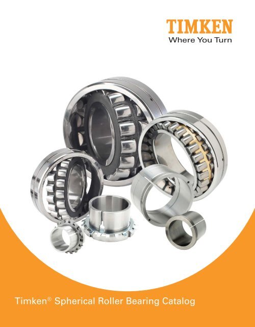
Timken ® <strong>Spherical</strong> <strong>Roller</strong> <strong>Bearing</strong> <strong>Catalog</strong>
A<br />
B<br />
C<br />
INDEX<br />
ENGINEERING<br />
Introduction . . . . . . . . . . . . . . . . . . . . . . . . . . . . . . . . . . . . . . . . . . . . . . . 17<br />
<strong>Roller</strong> <strong>Bearing</strong> Selection Process . . . . . . . . . . . . . . . . . . . . . . . . . . . 17<br />
Radial <strong>Spherical</strong> <strong>Roller</strong> <strong>Bearing</strong>s . . . . . . . . . . . . . . . . . . . . . . . . . . . . 18<br />
Cage Designs . . . . . . . . . . . . . . . . . . . . . . . . . . . . . . . . . . . . . . . . . . . . . 19<br />
Determination of Applied Loads and <strong>Bearing</strong> Reactions . . . . . 20-27<br />
Load Ratings, Equivalent Loads and <strong>Bearing</strong> Life . . . . . . . . . . . 28-33<br />
Tolerances . . . . . . . . . . . . . . . . . . . . . . . . . . . . . . . . . . . . . . . . . . . . . 34-49<br />
Mounting Designs . . . . . . . . . . . . . . . . . . . . . . . . . . . . . . . . . . . . . . 50-54<br />
Fitting Practices . . . . . . . . . . . . . . . . . . . . . . . . . . . . . . . . . . . . . . . . 55-56<br />
Lubrication and Seals . . . . . . . . . . . . . . . . . . . . . . . . . . . . . . . . . . . 57-67<br />
Speed, Heat and Torque . . . . . . . . . . . . . . . . . . . . . . . . . . . . . . . . . 68-71<br />
SPHERICAL ROLLER BEARINGS<br />
<strong>Bearing</strong> Types . . . . . . . . . . . . . . . . . . . . . . . . . . . . . . . . . . . . . . . . . . . . . 78<br />
Modifi cation Codes . . . . . . . . . . . . . . . . . . . . . . . . . . . . . . . . . . . . . . . . 79<br />
<strong>Spherical</strong> <strong>Roller</strong> <strong>Bearing</strong>s . . . . . . . . . . . . . . . . . . . . . . . . . . . . . . . 80-96<br />
Inch Shaft Adapter Accessories . . . . . . . . . . . . . . . . . . . . . . . . . . 97-102<br />
Mounting Procedures . . . . . . . . . . . . . . . . . . . . . . . . . . . . . . . . . .103-105<br />
SPHERICAL PILLOW BLOCKS<br />
Design and Construction . . . . . . . . . . . . . . . . . . . . . . . . . . . . . . . . . . 111<br />
Mounting . . . . . . . . . . . . . . . . . . . . . . . . . . . . . . . . . . . . . . . . . . . . . . . . 112<br />
Inch <strong>Spherical</strong> Pillow Blocks . . . . . . . . . . . . . . . . . . . . . . . . . . 113-122<br />
Inch Shaft Seals . . . . . . . . . . . . . . . . . . . . . . . . . . . . . . . . . . . . . . . . . . 123<br />
Inch Sine Bar Gages . . . . . . . . . . . . . . . . . . . . . . . . . . . . . . . . . . . . . . 124<br />
Inch Hydraulic Nuts . . . . . . . . . . . . . . . . . . . . . . . . . . . . . . . . . . . 125-127<br />
Inch Shaft Adapter Accessories . . . . . . . . . . . . . . . . . . . . . . . . 128-135<br />
SPHERICAL ROLLER BEARING METRIC ACCESSORIES<br />
Adapter Sleeves . . . . . . . . . . . . . . . . . . . . . . . . . . . . . . . . . . . . . . 144-151<br />
Hydraulic Adapter Sleeves . . . . . . . . . . . . . . . . . . . . . . . . . . . . 152-155<br />
Withdrawal Sleeves . . . . . . . . . . . . . . . . . . . . . . . . . . . . . . . . . . 156-165<br />
Hydraulic Withdrawal Sleeves . . . . . . . . . . . . . . . . . . . . . . . . . 166-173<br />
Locknuts. . . . . . . . . . . . . . . . . . . . . . . . . . . . . . . . . . . . . . . . . . . . . 174-179<br />
Lockwashers and Lockplates . . . . . . . . . . . . . . . . . . . . . . . . . . 180-183<br />
Conversion Tables . . . . . . . . . . . . . . . . . . . . . . . . . . . . . . . . . . . . 184-185<br />
Product Index . . . . . . . . . . . . . . . . . . . . . . . . . . . . . . . . . . . . . . . . . . . . 187<br />
SPHERICAL ROLLER BEARING CATALOG 3<br />
2<br />
2<br />
2
2<br />
2<br />
2<br />
SPHERICAL ROLLER BEARING CATALOG<br />
4 SPHERICAL ROLLER BEARING CATALOG<br />
TIMKEN. WHERE YOU TURN.<br />
The world turns to Timken for innovation to move ahead of the<br />
competition. Our contributions to advancing work and living<br />
standards – through innovations surrounding friction management<br />
and power transmission – are invaluable. We have played a role<br />
in virtually all major technologies that have shaped our age, from<br />
automobile travel to artificial hearts. You’ll find our products<br />
wherever you turn – on land, sea and in space.<br />
When customers turn to us, they are turning to a worldwide team<br />
of 25,000 associates. Because of our ability to help their products<br />
perform better, customers honor us with more than 300 awards<br />
each year. Whether it is a wheel assembly for a family vehicle,<br />
bearings for a roller coaster, repair services for rail bearings or steel<br />
for an aircraft engine shaft, we supply the products and services<br />
that help keep the world turning.<br />
FRICTION MANAGEMENT SOLUTIONS –<br />
A TOTAL SYSTEM APPROACH<br />
As needs change and advanced motion control systems evolve,<br />
Timken is leveraging its knowledge of friction management to offer a<br />
broader array of bearings, related products and integrated services<br />
to the marketplace. We supply quality products and services that<br />
extend beyond bearings to help all systems run smoothly.<br />
We are committed to providing a wide array of friction management<br />
solutions. Customers can benefi t by having Timken, a trusted name<br />
for more than 100 years, evaluate entire systems, not just individual<br />
components. This approach provides cost-effective solutions, while<br />
also helping to achieve specifi c objectives.
TECHNOLOGY THAT MOVES YOU<br />
Today, major industry turns to Timken for our ability to infl uence the<br />
fundamentals of motion through the creation, transfer, and control<br />
of power. We invest in people, attracting scholars, engineers and<br />
specialists from around the world. We invest in tools – computers,<br />
manufacturing equipment and state-of-the-art laboratories. And we<br />
invest in the future by identifying new concepts that will help Timken<br />
and its customers make their mark for years to come. Innovation<br />
is one of our core values.<br />
The return on our technology investment has grown exponentially.<br />
Our associates increase the reliability of Timken ® products and<br />
create designs that can set new performance standards. We help<br />
customers solve their immediate system issues, while developing<br />
the systems of tomorrow.<br />
Our teams of engineers and scientists are dedicated to using<br />
everything they know about friction management and power<br />
transmission. They translate the scientifi c aspects of metallurgy,<br />
bearing operating characteristics, lubrication, torque, noise,<br />
heat treatment, advanced processing concepts and application<br />
development into friction management solutions.<br />
Because our teams are located at technology centers in<br />
North America, Europe and Asia – as well as in our<br />
manufacturing facilities and field offices on<br />
six continents – customers have access to<br />
ideas and resources to transform concepts<br />
into reality. Our technology focuses on<br />
products, materials, processes and<br />
emerging technology to create new<br />
solutions.<br />
Introduction<br />
SPHERICAL ROLLER BEARING CATALOG 5
2<br />
2<br />
2<br />
SPHERICAL ROLLER BEARING CATALOG<br />
6 SPHERICAL ROLLER BEARING CATALOG<br />
BRANDS YOU CAN TRUST<br />
Timken has built a strong tradition of quality,<br />
technology and innovation. A long list of<br />
customer certifications provides solid<br />
evidence that our products have earned<br />
customer trust. As our founder, Henry<br />
Timken, said, “Don’t set your name to<br />
anything you will ever have cause to be<br />
ashamed of.”<br />
The Timken ® brand also refl ects the wellknown<br />
quality of Torrington ® and Fafnir ®<br />
product lines. By leveraging the benefi ts of<br />
these brands from design to distribution, Timken<br />
gives customers expanded options and the security<br />
of knowing that each box contains an industry-trusted<br />
product.<br />
ABOUT THE TIMKEN COMPANY<br />
• Timken is a global, Fortune 500 company.<br />
• Timken has ranked among the 250 largest U.S. industrial<br />
corporations since the 1920s, and it has been listed on the New<br />
York Stock Exchange since 1922.<br />
• Timken has 13 technical and engineering centers in North<br />
America, Europe and Asia.<br />
• Timken has more than 66 plants and 105 sales offi ces, customer<br />
service centers and distribution centers in 27 countries on six<br />
continents.
TIMKEN SPHERICAL ROLLER BEARINGS<br />
Timken spherical roller bearings exceed industry standards for<br />
superior quality and performance and are designed to manage<br />
high radial loads, even when misalignment, marginal lubrication,<br />
contamination, extreme speeds, or critical application stresses<br />
are present.<br />
That’s why industries such as power generation, oilfi eld, steel,<br />
aggregate, cement, mining and power transmission turn to Timken<br />
for a complete line of high-performance spherical roller bearings.<br />
Through expertly designed critical dimensions, such as roller and<br />
raceway contact geometry and topography, our spherical roller<br />
bearings are helping customers increase productivity by reducing<br />
downtime and extending maintenance cycles.<br />
PRODUCT BREADTH<br />
Timken offers a complete line of spherical roller bearing designs<br />
ranging from 25 to 1500 millimeter bore (0.98 to 59.06 inches).<br />
Included in this broad portfolio are two fundamental design types:<br />
the Type CJ style and Type YM/YMB design.<br />
Available in 25 to 200 millimeter bore (0.98 to 7.87 inches), Type<br />
CJ-style bearings offer higher load ratings for longer life and<br />
incorporate a stamped steel window-type cage. Similar to all<br />
spherical roller bearings, the CJ design compensates for dynamic<br />
and static misalignment and allows customers to use weldments<br />
for housing frames instead of complex castings.<br />
Type YM bearings feature precision-machined, roller-riding brass<br />
cages and are designed for harsh industrial environments. These<br />
bearings offer higher load ratings for longer life. For larger bore<br />
sizes, the Type YMB design incorporates an inner-ring, land-riding<br />
cage. The YM/YMB design is produced in sizes ranging from 30 to<br />
1500 millimeter bore (1.18 to 59.06 inches).<br />
Introduction<br />
In addition to the CJ and YM/YMB designs, Timken spherical<br />
roller bearings can be ordered with several enhancements<br />
and modifi cations to extend life and improve performance in<br />
specifi c applications. For example, large-bore spherical bearings<br />
sometimes operate below the bearing’s published speed rating,<br />
causing the cage to push a non-rotating roller across the raceways.<br />
This sliding action breaks down lubrication fi lm and can ultimately<br />
damage the bearing. To help protect the bearing components,<br />
our engineered surfaces coating minimizes skidding and sliding<br />
damage, while withstanding small-particle contamination. In some<br />
cases, engineered surfaces can extend bearing life by up to fi ve<br />
times standard designs, especially in demanding applications like<br />
paper and rolling mills.<br />
SPHERICAL ROLLER BEARING CATALOG 7
2<br />
2<br />
2<br />
SPHERICAL ROLLER BEARING CATALOG<br />
As a Timken customer, you receive an uncompromising standard of<br />
quality across the broadest range of bearings and related products.<br />
Brands like Timken, Torrington and Fafnir refl ect an extensive<br />
line of tapered, needle, spherical, cylindrical, ball bearings and<br />
mounted units ideal for virtually every industrial application. Our<br />
core products are complemented by an ever-growing line of<br />
friction management solutions including lubricants, single-point<br />
lubricators, maintenance tools, safety equipment,<br />
condition monitoring systems and repair services<br />
that help keep operations running smoothly.<br />
SAFETY END CAPS<br />
These easily installed caps offer a high degree of<br />
protection to maintenance personnel as well as to the<br />
bearings integrated within a housing.<br />
HOUSED UNITS<br />
Ball and spherical roller bearing pillow block units, featuring a<br />
unique sealing design, are easily installed.<br />
8 SPHERICAL ROLLER BEARING CATALOG<br />
CONDITION MONITORING DEVICES<br />
From wireless units to online systems, condition monitoring<br />
devices give you powerful diagnostic tools to help detect potential<br />
bearing problems, maximizing machine uptime and lowering<br />
maintenance costs.<br />
SPHERICAL ROLLER BEARING METRIC<br />
ACCESSORIES<br />
<strong>Bearing</strong> sleeves and locking devices, in a wide range of metric<br />
sizes, complement our line of Timken spherical roller bearings.<br />
These accessories are manufactured to the same quality<br />
standards as our bearings, helping to ensure a secure fi t to straight<br />
and stepped shafts. <strong>Bearing</strong> sleeves are available in two distinct<br />
designs, assembled adapter sleeves and withdrawal sleeves, in<br />
sizes up to 900 mm.
LUBRICANTS<br />
Our portfolio of lubricants includes lubricants developed<br />
by our tribology experts. These lubricants keep bearings<br />
running smoothly in a variety of industrial conditions,<br />
including high heat, food processing and high speed.<br />
Timken also offers a line of single-point lubricators to<br />
simplify the delivery of grease.<br />
REPAIR AND REPLACEMENT OPTIONS<br />
By choosing to have bearings and other elements remanufactured,<br />
customers save money in replacement costs and maintain a steady<br />
supply of parts instead of purchasing new parts during downtimes.<br />
Timken provides bearing repair services for any type of roller<br />
bearing design, regardless of manufacturer.<br />
MAINTENANCE HANDLING TOOLS<br />
Convenient handling devices give technicians the tools they need<br />
to install, remove and service bearings. Products include impact<br />
fi tting tools, induction heaters and hydraulic pullers.<br />
INDUSTRIAL SEALS<br />
Introduction<br />
Timken industrial seals are available in small-bore sizes, zero- to<br />
13-inches, as well as in metric and high-temperature varieties.<br />
We also provide tools to speed installation, deter seal and bearing<br />
damage and prevent premature seal leakage. The seals and tools<br />
can be applied in a full range of equipment used in thousands<br />
of applications, including manufacturing, off-highway, power<br />
transmission and oil<br />
refi neries.<br />
SPHERICAL ROLLER BEARING CATALOG 9
2<br />
2<br />
2<br />
SPHERICAL ROLLER BEARING CATALOG<br />
ABOUT THIS CATALOG<br />
Timken offers an extensive range of bearings and<br />
accessories in both imperial and metric sizes. For<br />
your convenience, size ranges are indicated both in<br />
millimeters and inches. Contact your Timken sales<br />
representative to learn more about our complete<br />
line for the special needs of your application.<br />
USING THIS CATALOG<br />
We are committed to providing our customers with<br />
maximum service and quality. This catalog contains<br />
dimensions, tolerances and load ratings, as well as<br />
an engineering section describing fi tting practices for<br />
shafts and housings, internal clearances, materials, and<br />
other bearing features. It can provide valuable assistance<br />
in the initial consideration of the type and characteristics of the<br />
bearing that may best suit your particular needs.<br />
CATALOG FEATURES<br />
Dimension and load rating data for the various types and styles of<br />
bearings is organized by size.<br />
ISO, DIN, and ABMA, as used in this catalog, refer to the International<br />
Organization for Standardization, Deutsches Institut für Normung<br />
EV and the American <strong>Bearing</strong> Manufacturers Association.<br />
TERMS AND CONDITIONS OF SALE<br />
All products described in this catalog are sold subject to Timken’s<br />
Terms and Conditions of Sale.<br />
It is understood that the buyer, in selecting and ordering from this<br />
catalog, which supersedes all previous editions, accepts all Timken<br />
Terms and Conditions of Sale, a copy of which may be obtained by<br />
your Timken sales offi ce.<br />
10 SPHERICAL ROLLER BEARING CATALOG<br />
Note: Product performance is affected by many factors beyond<br />
the control of Timken. Therefore, the suitability and feasibility<br />
of all designs and product selection should be validated by you.<br />
This catalog is provided solely to give you, a customer of Timken<br />
or its parent or affiliates, analysis tools and data to assist you in<br />
your design. No warranty, expressed or implied, including any<br />
warranty of fitness for a particular purpose, is made by Timken.<br />
Timken products are sold subject to the Limited Warranty.
LIMITED WARRANTY<br />
We warrant for a period of one year from the date of shipment that<br />
our products shall be free of defects in material and workmanship,<br />
as shall be determined by our manufacturing standards, and shall<br />
conform to the description on the face of this acknowledgment.<br />
THE WARRANTY DESCRIBED HEREIN SHALL BE IN LIEU OF ANY<br />
OTHER WARRANTY, EXPRESS OR IMPLIED, INCLUDING BUT NOT<br />
LIMITED TO ANY IMPLIED WARRANTY OF MERCHANTABILITY<br />
OR FITNESS FOR A PARTICULAR PURPOSE. The terms contained<br />
herein constitute the entire agreement of the parties and the<br />
warranty representations of the seller. There are no other<br />
representations, warranties, or guarantees applicable to the sale of<br />
our products unless otherwise expressly agreed to by us in writing.<br />
SPECIAL APPLICATIONS<br />
Some products, such as for aerospace applications, are made to<br />
special standards, and only the original equipment manufacturer<br />
can determine if a particular bearing is suitable for use in their<br />
equipment.<br />
WARNING<br />
Introduction<br />
Failure to observe the following warnings could lead to a risk of serious bodily harm:<br />
Proper maintenance and handling practices are critical. Failure to follow installation instructions<br />
and to maintain proper lubrication can result in equipment failure creating a risk of serious bodily<br />
harm. Never spin a bearing with compressed air. The rollers may be forcefully expelled creating<br />
a risk of serious bodily harm.<br />
PURCHASER’S EXCLUSIVE REMEDY/<br />
SELLER’S EXPRESS LIMIT OF LIABILITY<br />
Purchaser’s exclusive remedy for any warranty claim, or for<br />
any claim arising out of the purchase or use of our products,<br />
shall be the replacement of said products. We will replace our<br />
products, without charge to the purchaser, f.o.b. our point of<br />
shipment. We will not be liable for any consequential, incidental,<br />
or other damages sustained by purchaser, including but not<br />
limited to, loss of profits or revenue, loss of use of product, cost<br />
of capital, cost of substituted product, facilities, services, or<br />
claims of purchaser’s customers for any damages. Any warranty<br />
claim of purchaser must be made within one year of the date of<br />
shipment of the product. This exclusive remedy applies regardless<br />
of the nature of purchaser’s claim, whether in contract, tort,<br />
express or implied warranty, negligence or strict liability, upon<br />
which damages are claimed and regardless of whether the<br />
same is due to our negligence or any defect in our product.<br />
SPHERICAL ROLLER BEARING CATALOG 11
2<br />
2<br />
2<br />
SPHERICAL ROLLER BEARING CATALOG<br />
ROLLER BEARINGS<br />
TO IDENTIFY: SPHERICAL ROLLER BEARINGS<br />
The basic bearing number, plus any applicable modifi cation<br />
code, is marked on the outer ring face (e.g., 22315CJW33).<br />
If the bearing has a tapered inner ring bore, the letter K is<br />
marked on the inner ring face (in addition to the above outer ring<br />
face marking).<br />
Replacement bearings, if straight bore, should be ordered by<br />
specifying bearing number plus the suffi x nomenclature marked<br />
on outside face (e.g., 22315CJW33).<br />
Replacement bearings, if a tapered bore, should be ordered<br />
as described above, except include the suffi x “K” following basic<br />
bearing number (e.g., 22315KCJW33).<br />
Note: Letter symbols marked on recessed pads on ring faces<br />
are not part of bearing nomenclature and therefore not relevant<br />
to replacement bearing number identifi cation.<br />
For a comprehensive description of spherical roller bearing<br />
nomenclature, see page 76.<br />
TO IDENTIFY: SPHERICAL ROLLER BEARING PILLOW BLOCK<br />
The end cap and/or base housing is marked with a pillow<br />
block housing number (e.g., SAF517). The pillow block assembly<br />
number is closely affiliated with the housing number (e.g.,<br />
SAF22517). Here, pillow block assembly uses the pillow block<br />
housing SAF517.<br />
For a comprehensive description of spherical roller bearing<br />
pillow block nomenclature, see page 108.<br />
HOW TO ORDER A REPLACEMENT BEARING<br />
The ordering of correct replacement bearings is vital to<br />
minimizing downtime and ensuring the correct interchanges.<br />
Timken suggests that you follow these simple steps to identify your<br />
bearings and then proceed to the appropriate catalog section for<br />
the correct bearing catalog number. If no identifi cation number is<br />
legible, measure the following dimensions:<br />
1. Inner ring bore<br />
2. Outer ring outside diameter<br />
3. Inner width and outer width (not always the same<br />
dimension)<br />
4. Shape of the outer ring: beveled vs. straight O.D.<br />
5. List the unique features of the bearing or components such<br />
as: relubrication holes in the outer ring, wireloc (snap ring)<br />
groove in the outer ring O.D. Replacement<br />
and nomenclature information for Timken bearings is found<br />
under the “Introduction” section for each<br />
bearing type.<br />
The term “modifi cation code” refers to additional information,<br />
describing details and requirements, for specific bearing<br />
applications. A basic Timken bearing part number may be produced<br />
in a variety of special modifi cations to meet different application<br />
needs. The word “modification” in this context refers to all<br />
changes from standard for both commercial and non-commercial<br />
applications. This meaning is different from the term “modifi ed for<br />
use in military applications” referred to in the ITAR regulations.<br />
12 SPHERICAL ROLLER BEARING CATALOG<br />
CJ<br />
<strong>Bearing</strong><br />
Number<br />
Locations<br />
Housing Number (Cast)<br />
Letter K<br />
Straight Tapered<br />
Bore Bore
2<br />
2<br />
2<br />
SPHERICAL ROLLER BEARING CATALOG<br />
14 SPHERICAL ROLLER BEARING CATALOG<br />
INTRODUCTION<br />
A ENGINEERING<br />
B SPHERICAL ROLLER BEARINGS<br />
SPHERICAL PILLOW BLOCKS<br />
C SPHERICAL ROLLER BEARING<br />
METRIC ACCESSORIES
A<br />
ENGINEERING<br />
A ENGINEERING<br />
ENGINEERING<br />
Introduction . . . . . . . . . . . . . . . . . . . . . . . . . . . . . . . . . . . . . . . . . . . 17<br />
<strong>Roller</strong> <strong>Bearing</strong> Selection Process . . . . . . . . . . . . . . . . . . . . . . . . 17<br />
Radial <strong>Spherical</strong> <strong>Roller</strong> <strong>Bearing</strong>s . . . . . . . . . . . . . . . . . . . . . . . . 18<br />
Cage Designs . . . . . . . . . . . . . . . . . . . . . . . . . . . . . . . . . . . . . . . . . . 19<br />
Determination of Applied Loads and <strong>Bearing</strong> Reactions . 20-27<br />
Load Ratings, Equivalent Loads and <strong>Bearing</strong> Life . . . . . . . 28-33<br />
Tolerances . . . . . . . . . . . . . . . . . . . . . . . . . . . . . . . . . . . . . . . . . 34-49<br />
Mounting Designs. . . . . . . . . . . . . . . . . . . . . . . . . . . . . . . . . . . 50-54<br />
Fitting Practices . . . . . . . . . . . . . . . . . . . . . . . . . . . . . . . . . . . . 55-56<br />
Lubrication and Seals . . . . . . . . . . . . . . . . . . . . . . . . . . . . . . . 57-67<br />
Speed, Heat and Torque . . . . . . . . . . . . . . . . . . . . . . . . . . . . . . 68-71<br />
SPHERICAL ROLLER BEARING CATALOG 15<br />
A
A A<br />
ENGINEERING<br />
16 SPHERICAL ROLLER BEARING CATALOG<br />
ENGINEERING<br />
A
INTRODUCTION<br />
Timken is a leader in the advancement of bearing technology.<br />
Expert craftsmanship, well-equipped production facilities, and a<br />
continuing investment in technology programs ensure that our<br />
products are synonymous with quality and reliability. Today, our<br />
plants manufacture thousands of bearing types and sizes to handle<br />
a wide range of application requirements.<br />
ROLLER BEARING SELECTION PROCESS<br />
<strong>Bearing</strong> selection is a process of evaluating the suitability of<br />
bearings for specifi c industrial applications. The quality of the<br />
available information to make these selections will play a major role<br />
in determining the success of the bearing choice.<br />
The fi rst step in bearing selection is identifying the proper roller<br />
element type, whether it is a ball, needle, cylindrical, spherical or<br />
tapered roller bearing. Each roller bearing type has advantages and<br />
disadvantages that are design-specifi c and will affect such things as<br />
the loads and speeds the bearing can sustain in the application.<br />
Next, assess the size constraints of the bearing envelope or<br />
available space. This is done by considering the minimum shaft<br />
diameter, maximum housing bore and available width in the bearing<br />
application. After the bearing envelope is defi ned, search the catalog<br />
for bearings with bores, outer diameters and widths that will fi t in<br />
the bearing envelope. There may be several bearings with different<br />
load-carrying capacities available that fi t in the envelope.<br />
ENGINEERING<br />
Tapered <strong>Roller</strong> Thrust Tapered Cylindrical <strong>Roller</strong> Thrust Cylindrical <strong>Spherical</strong> <strong>Roller</strong> Thrust <strong>Spherical</strong> Thrust Ball Needle <strong>Roller</strong> Thrust Needle<br />
Characteristic <strong>Bearing</strong> <strong>Roller</strong> <strong>Bearing</strong> <strong>Bearing</strong> <strong>Roller</strong> <strong>Bearing</strong> <strong>Bearing</strong> <strong>Roller</strong> <strong>Bearing</strong> Ball <strong>Bearing</strong> <strong>Bearing</strong> <strong>Bearing</strong> <strong>Roller</strong> <strong>Bearing</strong><br />
Pure Radial Load Excellent Unsuitable Excellent Unsuitable Excellent Unsuitable Good Poor Excellent Unsuitable<br />
Pure Axial Load Good Excellent Unsuitable Good Fair Excellent Fair Excellent Unsuitable Excellent<br />
Combined Load Excellent Fair Fair Unsuitable Excellent Fair Good Poor Unsuitable Unsuitable<br />
Moment Load Fair Poor Unsuitable Unsuitable Unsuitable Unsuitable Good Poor Fair Unsuitable<br />
High Stiffness Excellent Excellent Good Excellent Good Good Fair Good Good Excellent<br />
Quiet Running Fair Fair Good Poor Fair Poor Excellent Good Good Fair<br />
Low Friction Fair Fair Good Poor Fair Fair Excellent Excellent Good Good<br />
Misalignment Poor Poor Poor Unsuitable Excellent Excellent Good Poor Poor Poor<br />
Locating Position<br />
Excellent Good Fair Fair Good Good Good Excellent Unsuitable Excellent<br />
(Fixed)<br />
Non-Locating<br />
Good Unsuitable Excellent Unsuitable Fair Unsuitable Good Unsuitable Good Unsuitable<br />
Position (Floating)<br />
Speed Good Good Good Poor Fair Fair Excellent Excellent Good Poor<br />
Table 1. Comparison of rolling element bearing types.<br />
Anti-friction bearings inherently manage broad ranges<br />
of speed and many combinations of radial and thrust loads.<br />
Environmental conditions such as low and high temperature,<br />
dust and dirt, moisture, and unusual mounting conditions, affect<br />
bearing operation.<br />
If complex bearing applications are involved, consult your<br />
Timken representative.<br />
Of the bearings fi tting the envelope, the next step is to determine<br />
which of these bearings will give the desired life in the application<br />
by performing a bearing life analysis.<br />
The bearing selection is completed once the design options<br />
are chosen. These options include cage type, cylindrical roller<br />
bearing fl ange arrangements, radial internal clearance or setting,<br />
and precision level and lubrication. These options are selected<br />
based on the application’s speed, temperature, mounting and<br />
loading conditions, and will enable you to achieve optimum bearing<br />
performance and life.<br />
This catalog assumes that a spherical roller bearing has been<br />
selected for the application, and highlights the data and methods<br />
to use during the selection process. For a closer look, your Timken<br />
representative can provide you with expert computer analysis to give<br />
you the most detailed information for your bearing application.<br />
SPHERICAL ROLLER BEARING CATALOG 17<br />
A
A A<br />
ENGINEERING<br />
RADIAL SPHERICAL ROLLER BEARINGS<br />
The principle styles of radial spherical roller bearings that<br />
Timken offers are: CJ, YM, YMD, and YMB.<br />
CJ<br />
YM / YMB<br />
18 SPHERICAL ROLLER BEARING CATALOG<br />
Tapered Bore <strong>Bearing</strong> with<br />
Adapter Sleeve Assembly<br />
Fig. 1. Common design styles of Timken spherical roller bearings.<br />
YM bearings offer the greatest range of sizes in all series. They<br />
combine design experience with proven performance in many<br />
industries.<br />
All of the newer styles (CJ, YM, YMB and YMD) offer higher load<br />
ratings for longer life. CJ bearings include a stamped steel, window<br />
style cage and are suitable for a broad range of general service<br />
applications. For extreme conditions of use, the YM, YMB and YMD<br />
styles with a machined brass cage should be considered.<br />
All styles are available in straight or tapered bores. Tapered bore<br />
bearings can be ordered by placing a “K” immediately after the<br />
numbers in the bearing description (e.g., 22311KYM). Tapered bore<br />
bearings are available with adapter sleeve assemblies consisting<br />
of sleeve, locknut and washer. Adapter sleeve assemblies are<br />
designated SNW (e.g., SNW117).<br />
Fig. 2. Standard ISO/ABMA series available from Timken.<br />
Timken spherical roller bearings have been developed to<br />
accommodate radial and axial loads. The internal geometry allows<br />
the inner ring to accommodate misalignment. This capability is<br />
unique to spherical roller bearings, allowing machine designers<br />
more tolerance and less restrictive assembly. Other data is<br />
listed.<br />
Timken spherical roller bearings are available in a ten<br />
dimensional series conforming to ISO and ANSI/ABMA standards.<br />
See Fig. 2 for size range illustration.<br />
OPTIONAL FEATURES AVAILABLE WITH TIMKEN<br />
SPHERICAL ROLLER BEARINGS<br />
W33 Lubrication Groove and Oil Holes<br />
A lubrication groove and three oil holes are provided in the<br />
bearing outer ring. This eliminates the expense of machining<br />
a channel in the housing bore for introducing lubricant to the<br />
bearing. This design feature allows the lubricant to fl ow between<br />
the roller paths, through a single lubrication fi tting. The lubricant<br />
moves laterally outward from the center of the bearing, reaching<br />
all contact surfaces and “fl ushing” the bearing. To order, add the<br />
suffi x “W33” to the bearing number (e.g., 22216CJW33).<br />
W22 Selected Outside Diameter <strong>Bearing</strong>s<br />
<strong>Bearing</strong>s with selected outside diameters are required in some<br />
applications. Timken spherical roller bearings are available with<br />
reduced outside diameter tolerance. This allows a close control<br />
of the fi t between the bearing and housing.<br />
To specify this feature, add the suffi x “W22” to the bearing<br />
number (e.g., 22216CJW22).<br />
Additional features are available, consult your Timken<br />
representative for more information.
CAGE DESIGNS<br />
Cages (sometimes referred to as rolling element separators or<br />
retainers) perform an important function in the proper operation of<br />
rolling bearings. They maintain uniform rolling element spacing in<br />
the races of the inner and outer rings of the bearings as the rolling<br />
elements pass into and out of the load zones. Timken has developed<br />
cage types to meet various service requirements. Temperature<br />
limitations are described in the temperature limitations portion of<br />
the Engineering section on page 70.<br />
CAGE DESCRIPTIONS<br />
Brass Cages<br />
YM, YMB and YMD bearing cages are centrifugally cast and<br />
precision machined from brass. (Note that the brass grades used<br />
are often commercially termed bronze.) Their rugged construction<br />
provides an advantage in more severe applications. The open-end<br />
design permits lubricant to reach all surfaces easily, assuring ample<br />
lubrication and a cooler running bearing.<br />
YM and YMB are both one-piece designs that are differentiated<br />
by their means of guidance within the bearing. With YM designs,<br />
the cage mass is low and the rollers are used for guidance, while<br />
YMB cage designs typically have more mass and guide on the<br />
inner ring.<br />
YMD cages are similar to YMB, except they have a two-piece<br />
design. Two independent cages, one for each row of rollers, are<br />
assembled into an individual bearing. This allows each row of<br />
rollers to rotate independently when required by the application,<br />
and prevents bending of the cage fi ngers.<br />
VCSM designs are similar to YM in that they are single piece,<br />
fi nger style cages.<br />
Stamped Steel Cages<br />
These cages are used in CJ design to permit extra load carrying<br />
capabilities in the bearing compared to YM and YMB designs. This<br />
is accomplished through the use of a window style cage, which<br />
retains the rollers axially thus eliminating the need for ribs on the<br />
inner ring and allowing longer rollers. The window style cage<br />
is also held on both ends as opposed to fi nger style cages, thus<br />
allowing thinner bridge sections and often more rollers.<br />
The CJ design also has two independent cages, one for each<br />
row of rollers, assembled in an individual bearing. This feature<br />
serves to prevent cage bending when the operating environment<br />
is favorable for this to occur. Some CJ bearings utilize a cast iron<br />
fl oating ring to guide the cage. Use of the fl oating ring is based on<br />
size and mass of the cage.<br />
The VCSJ design is a fi nger style cage, similar to the VCSM,<br />
however it is pressed steel instead of brass.<br />
Pin Type Cages<br />
Large diameter spherical roller bearings can be supplied with<br />
these cages. The design of pin type cages permits an increased<br />
roller complement, giving the bearing enhanced load carrying<br />
ability. Consult your Timken representative for suggestions on the<br />
application of this cage.<br />
YM Cage<br />
YMB Cage<br />
CJ Cage<br />
Pin Type Cage<br />
ENGINEERING<br />
Fig. 3. Common cage styles for Timken spherical roller bearings.<br />
SPHERICAL ROLLER BEARING CATALOG 19<br />
A
A A<br />
ENGINEERING<br />
DETERMINATION OF APPLIED LOADS AND BEARING REACTIONS<br />
The following equations are used to determine the forces developed by machine elements commonly encountered in bearing applications.<br />
SUMMARY OF SYMBOLS USED TO DETERMINE APPLIED BEARING LOADS AND BEARING ANALYSIS<br />
Symbol Description Units<br />
a1 a2 a3 a3d a3k a3l a3m a3p ae b<br />
Reliability Life Factor<br />
Material Life Factor<br />
Operating Condition Life Factor<br />
Debris Life Factor<br />
Load Zone Life Factor<br />
Lubrication Life Factor<br />
Misalignment Life Factor<br />
Low Load Life Factor<br />
Effective <strong>Bearing</strong> Spread<br />
Tooth Length<br />
mm, in.<br />
mm, in.<br />
c , c 1 2<br />
C<br />
Linear Distance (positive or negative)<br />
Dynamic Radial Load Rating<br />
mm, in.<br />
N, lbf<br />
C0 Cp Static Load Rating<br />
Specifi c Heat of Lubricant<br />
N, lbf<br />
J/(kg x ˚C),<br />
BTU/(lb x ˚F)<br />
d <strong>Bearing</strong> bore diameter mm, in.<br />
d0 dc dm ds D<br />
Mean inner race diameter<br />
Distance Between Gear Centers<br />
Mean <strong>Bearing</strong> Diameter<br />
Shaft inside diameter<br />
<strong>Bearing</strong> outside diameter<br />
mm, in.<br />
mm, in.<br />
mm, in.<br />
mm, in.<br />
mm, in.<br />
D0 Dh Dm Mean outer race diameter<br />
Housing outside diameter<br />
Mean Diameter or Effective Working<br />
Diameter of a Sprocket, Pulley, Wheel or Tire<br />
mm, in.<br />
mm, in.<br />
Also, Tapered <strong>Roller</strong> Mean Large Rib Diameter mm, in.<br />
DmG DmP DmW DpG DpP DpW e<br />
Mean or Effective Working Diameter of the Gear mm, in.<br />
Effective Working Diameter of the Pinion mm, in.<br />
Effective Working Diameter of the Worm mm, in.<br />
Pitch Diameter of the Gear mm, in.<br />
Pitch Diameter of the Pinion mm, in.<br />
Pitch Diameter of the Worm mm, in.<br />
Life Exponent<br />
Lubricant Flow Rate L/min, U.S. pt/min<br />
0<br />
1<br />
B<br />
F<br />
Viscous Dependent Torque Coeffi cient<br />
Load Dependent Torque Coeffi cient<br />
Belt or Chain Pull Factor<br />
General Term for Force N, lbf<br />
Fa FaG FaP FaW Fb Fc Fr FsG FsP FsW Fte FtG FtP FtW FW h<br />
Applied Thrust (Axial) Load<br />
Thrust Force on Gear<br />
Thrust Force on Pinion<br />
Thrust Force on Worm<br />
Belt or Chain Pull<br />
Centrifugal Force<br />
Applied Radial Load<br />
Separating Force on Gear<br />
Separating Force on Pinion<br />
Separating Force on Worm<br />
Tractive Effort on Vehicle Wheels<br />
Tangential Force on Gear<br />
Tangential Force on Pinion<br />
Tangential Force on Worm<br />
Force of Unbalance<br />
Horizontal (used as subscript)<br />
N, lbf<br />
N, lbf<br />
N, lbf<br />
N, lbf<br />
N, lbf<br />
N, lbf<br />
N, lbf<br />
N, lbf<br />
N, lbf<br />
N, lbf<br />
N, lbf<br />
N, lbf<br />
N, lbf<br />
N, lbf<br />
N, lbf<br />
H Power (kW or hp) kW, hp<br />
Table 2.<br />
20 SPHERICAL ROLLER BEARING CATALOG<br />
Symbol Description Units<br />
k Centrifugal Force Constant lbf/RPM2 k <strong>Bearing</strong> Torque Constant<br />
1<br />
k , k , k Dimensional Factor to calculate heat generation<br />
4 5 6<br />
L Lead Axial Advance of a Helix for<br />
One Complete Revolution mm, in.<br />
L Distance between bearing geometric<br />
center lines mm, in.<br />
m Gearing Ratio<br />
M <strong>Bearing</strong> Operating Torque or Moment N-m, N-mm, lb-in.<br />
n <strong>Bearing</strong> Operating Speed or<br />
General Term for Speed rot/min, RPM<br />
nG nP nW NG NP NS P0 P0a P0r Pr Q<br />
Gear Operating Speed (RPM)<br />
Pinion Operating Speed (RPM)<br />
Worm Operating Speed (RPM)<br />
Number of Teeth in the Gear<br />
Number of Teeth in the Pinion<br />
Number of Teeth in the Sprocket<br />
Static Equivalent Load<br />
Static Equivalent Thrust (Axial) Load<br />
Static Equivalent Radial Load<br />
Dynamic Equivalent Radial Load<br />
Generated Heat or Heat Dissipation Rate<br />
rot/min, RPM<br />
rot/min, RPM<br />
rot/min, RPM<br />
N, lbf<br />
N, lbf<br />
N, lbf<br />
N, lbf<br />
W, BTU/min<br />
T Torque N-m, lb.-in.<br />
v Vertical (used as subscript)<br />
V Linear Velocity or Speed km/h, mph<br />
Vr Rubbing or Surface<br />
Velocity m/s, fpm<br />
X Dynamic Radial Load Factor<br />
X0 Y<br />
Static Radial Load Factor<br />
Dynamic Thrust (Axial) Load Factor<br />
Y0 ΥG Static Thrust (Axial) Load Factor<br />
Bevel Gearing – Gear Pitch Angle<br />
Hypoid Gearing – Gear Root Angle<br />
deg.<br />
deg.<br />
ΥP Bevel Gearing – Pinion Pitch Angle<br />
Hypoid Gearing – Pinion Face Angle<br />
deg.<br />
deg.<br />
Coeffi cient of linear expansion mm/mm/ ˚C,<br />
in./in./˚F<br />
s Interference fi t of inner race on shaft mm, in.<br />
h Interference fi t of outer race in housing mm, in.<br />
η Effi ciency, Decimal Fraction<br />
θ1, θ2, θ3 Gear Mesh Angles Relative to the<br />
Reference Plane deg.<br />
θi, θo Oil inlet or outlet temperature ˚C, ˚F<br />
λ Worm Gear Lead Angle deg.<br />
μ Coeffi cient of Friction<br />
v Lubricant Kinematic Viscosity cSt<br />
σ0 G<br />
Approximate Maximum Contact Stress<br />
Normal Tooth Pressure Angle for the Gear<br />
MPa, psi<br />
deg.<br />
P Normal Tooth Pressure Angle for the Pinion deg.<br />
G Helix (Helical) or Spiral Angle for the Gear deg.<br />
P Helix (Helical) or Spiral Angle for the Pinion deg.<br />
T Temperature difference between shaft/inner<br />
race + rollers and housing/bearing outer race ˚C, ˚F<br />
Lubricant Density kg/m3 , lb/ft3
DETERMINATION OF APPLIED LOADS AND BEARING REACTIONS - continued<br />
GEARING<br />
Spur Gearing (Fig. 4)<br />
Tangential Force:<br />
F tG = (1.91 x 10⁷ ) H (newtons)<br />
D pG n G<br />
= (1.26 x 10⁵ ) H (pounds-force)<br />
D pG n G<br />
Separating Force:<br />
F sG = F tG tan G<br />
Single Helical Gearing (Fig. 5)<br />
Tangential Force:<br />
FsP<br />
F tG = (1.91 x 10⁷ ) H (newtons)<br />
D pG n G<br />
FtP<br />
= (1.26 x 10⁵ ) H (pounds-force)<br />
D pG n G<br />
Separating Force:<br />
F sG =<br />
Thrust Torce:<br />
F aG =<br />
FsP<br />
FaP<br />
FtP<br />
Fig. 4<br />
Spur gearing.<br />
FsG<br />
FsG<br />
FtG<br />
Fig. 5. Helical gearing.<br />
FtG<br />
FaG<br />
ENGINEERING<br />
Straight Bevel and Zerol Gearing with Zero<br />
Degrees Spiral<br />
In straight bevel and zerol gearing, the gear forces tend to push<br />
the pinion and gear out of mesh, such that the direction of the thrust<br />
and separating forces are always the same regardless of direction<br />
of rotation. (Fig. 6) In calculating the tangential force, (F or F ),<br />
tP tG<br />
for bevel gearing, the pinion or gear mean diameter, (D or DmG ), is<br />
mP<br />
used instead of the pitch diameter, (D or D ). The mean diameter<br />
pP pG<br />
is calculated as follows:<br />
D = D - b sin mG pG G or DmP = DpP - b sin P<br />
In straight bevel and zerol gearing<br />
F tP = F tG<br />
Clo ck w ise<br />
C o u n te r clo ck w ise<br />
FaG<br />
FsG<br />
FtG<br />
+ Thrust from<br />
Positive<br />
pinion apex<br />
Fig. 6.<br />
Straight bevel and zerol gears<br />
– thrust and separating force<br />
are always in same direction<br />
regardless of direction of rotation.<br />
FaP<br />
FsP<br />
Fig. 7.<br />
Straight bevel gearing.<br />
SPHERICAL ROLLER BEARING CATALOG 21<br />
A
A A<br />
ENGINEERING<br />
DETERMINATION OF APPLIED LOADS AND BEARING REACTIONS - continued<br />
Pinion:<br />
Tangential Force:<br />
F tP = (1.91 x 10⁷ ) H (newtons)<br />
D mP n P<br />
= (1.26 x 10⁵ ) H (pounds-force)<br />
D mP n P<br />
Thrust Force:<br />
Separating Force:<br />
Gear:<br />
Tangential Force:<br />
F tG = (1.91 x 10⁷ ) H (newtons)<br />
D mG n G<br />
= (1.26 x 10⁵ ) H (pounds-force)<br />
D mG n G<br />
Thrust Force:<br />
Separating Force:<br />
Spiral Bevel and Hypoid Gearing<br />
In spiral bevel and hypoid gearing, the direction of the thrust<br />
and separating forces depends upon spiral angle, hand of spiral,<br />
direction of rotation, and whether the gear is driving or driven (see<br />
Table 3). The hand of the spiral is determined by noting whether the<br />
tooth curvature on the near face of the gear (Fig. 8) inclines to the<br />
left or right from the shaft axis. Direction of rotation is determined<br />
by viewing toward the gear or pinion apex.<br />
In spiral bevel gearing:<br />
F = F tP tG<br />
In hypoid gearing:<br />
Hypoid pinion effective working diameter:<br />
( ) ( )<br />
22 SPHERICAL ROLLER BEARING CATALOG<br />
FaG<br />
FsG<br />
Clo ck w ise<br />
Co u n te r clo ck w ise<br />
FtG<br />
+ _<br />
Positive<br />
Thrust away from<br />
pinion apex<br />
N egative<br />
Thrust toward<br />
pinion apex<br />
Fig. 8.<br />
Spiral bevel and hypoid gears – the direction<br />
of thrust and separating forces depends<br />
upon spiral angle, hand of spiral, direction<br />
of rotation, and whether the gear is driving<br />
or driven.<br />
FtP<br />
FaP<br />
FsP<br />
Fig. 9.<br />
Spiral bevel and<br />
hypoid gearing.
DETERMINATION OF APPLIED LOADS AND BEARING REACTIONS - continued<br />
Table 3.<br />
Driving member rotation Thrust force Separating force<br />
Right hand spiral<br />
clockwise<br />
or<br />
Left hand spiral<br />
counterclockwise<br />
Right hand spiral<br />
counterclockwise<br />
or<br />
Left hand spiral<br />
clockwise<br />
Straight Worm Gearing<br />
Worm:<br />
Tangential Force:<br />
F tW = (1.91 x 10⁷ ) H (newtons)<br />
D pW n W<br />
= (1.26 x 10⁵ ) H (pounds-force)<br />
D pW n W<br />
Thrust Force:<br />
or<br />
Separating Force:<br />
SPIRAL BEVEL AND HYPOID GEARING EQUATIONS<br />
Driving member<br />
Driven member<br />
Driving member<br />
Driven member<br />
FtG<br />
FaG<br />
FsG<br />
FsW<br />
Fig. 10.<br />
Straight worm gearing.<br />
FtW<br />
FaW<br />
Driving member<br />
Driven member<br />
Driving member<br />
Driven member<br />
ENGINEERING<br />
SPHERICAL ROLLER BEARING CATALOG 23<br />
A
A A<br />
ENGINEERING<br />
DETERMINATION OF APPLIED LOADS AND BEARING REACTIONS - continued<br />
Worm Gear:<br />
Tangential Force:<br />
or<br />
Thrust Force:<br />
F aG = (1.91 x 10⁷ ) H (newtons)<br />
D pW n W<br />
= (1.26 x 10⁵ ) H (pounds-force)<br />
D pW n W<br />
Separating Force:<br />
Where:<br />
or<br />
and<br />
( )<br />
( )<br />
Metric System:<br />
*μ = 5.34 x 10 -7 3<br />
Vr + 0.146<br />
- 0.103<br />
0.09 Vr (m/s)<br />
Inch System:<br />
μ* = 7 x 10 -14 3<br />
Vr + 0.235<br />
- 0.103<br />
0.09 Vr (fpm)<br />
*Approximates coeffi cient of friction as given in AGMA standard 440.04, October 1971, Table<br />
4, for 0.015 to 15 m/s (3 to 3000 fpm) rubbing velocity range.<br />
24 SPHERICAL ROLLER BEARING CATALOG<br />
Double Enveloping Worm Gearing<br />
Worm<br />
Tangential Force:<br />
F tW = (1.91 x 10⁷ ) H (newtons)<br />
D mW n W<br />
= (1.26 x 10⁵ ) H (pounds-force)<br />
D mW n W<br />
* Thrust Force:<br />
F aW = 0.98 F tG<br />
Separating Force:<br />
Worm Gear:<br />
** Tangential Force:<br />
or<br />
Thrust Force:<br />
F aG = (1.91 x 10⁷ ) H (newtons)<br />
D mW n W<br />
= (1.26 x 10⁵ ) H (pounds-force)<br />
D mW n W<br />
Separating Force:<br />
Where:<br />
= effi ciency (refer to manufacturer’s catalog)<br />
D mW = 2d c -0.98 D pG<br />
Lead angle at center of worm:<br />
= tan -1<br />
n W<br />
n W<br />
DpG ( m DpW )<br />
* Use this value for FtG for bearing loading<br />
calculations on worm gear shaft. For torque<br />
calculations, use the following F tG equations.<br />
or<br />
= tan -1<br />
** Use this value for<br />
calculating torque in<br />
subsequent gears and<br />
shafts. For bearing loading<br />
calculations, use the<br />
equation for F aW.<br />
L ( )<br />
D pW
DETERMINATION OF APPLIED LOADS AND BEARING REACTIONS - continued<br />
BELT AND CHAIN DRIVE FACTORS<br />
Dm Due to variations of belt tightness as set by various operators,<br />
an exact equation relating total belt pull to tension F on the tight<br />
1<br />
side and tension F on the slack side, Fig. 11, is diffi cult to establish.<br />
2<br />
The following equation and Table 4 may be used to estimate the<br />
total pull from various types of belts and pulley, and chain and<br />
Fb sprocket designs.<br />
F b =<br />
Standard roller chain sprocket mean diameter:<br />
D m =<br />
(1.91 x 10⁷ ) H B (newtons)<br />
D m n<br />
= (1.26 x 10⁵ ) H B (pounds-force)<br />
D m n<br />
P<br />
180<br />
sin<br />
Ns ( )<br />
SHOCK LOADS<br />
It is diffi cult to determine the exact effect that shock loading has<br />
on bearing life. The magnitude of the shock load depends on the<br />
masses of the colliding bodies, their velocities, and deformations<br />
at impact.<br />
The effect on the bearing depends on how much of the shock is<br />
absorbed between the point of impact and the bearings, as well as<br />
whether the shock load is great enough to cause bearing failure. It<br />
also is dependent on frequency and duration of shock loads.<br />
As a minimum, a suddenly applied load is equivalent to twice<br />
its static value. It may be considerably more than this, depending<br />
on the velocity of impact.<br />
Shock involves a number of variables that generally are not<br />
known or easily determined. Therefore, it is good practice to rely<br />
on experience. Timken has years of experience with many types of<br />
equipment under the most severe loading conditions. Your Timken<br />
representative should be consulted on any application involving<br />
unusual loading or service requirements.<br />
CENTRIFUGAL FORCE<br />
Centrifugal force resulting from imbalance in a rotating<br />
member:<br />
F c = F w r n2 (newtons)<br />
8.94 x 10 5<br />
= F w r n2 (pounds-force)<br />
3.52 x 10 4<br />
Fig. 9-8<br />
Fig. 11.<br />
Belt or chain drive.<br />
F 2 = Tension, slack side<br />
F 1 = Tension, tight side<br />
ENGINEERING<br />
Type B<br />
Chains, single .............................................. 1.00<br />
Chains, double ............................................ 1.25<br />
“V” belts...................................................... 1.50<br />
Table 4. Belt or chain pull factor based on 180 degrees angle of wrap.<br />
TRACTIVE EFFORT AND WHEEL SPEED<br />
The relationships of tractive effort, power, wheel speed<br />
and vehicle speed are:<br />
H =<br />
H =<br />
n =<br />
n =<br />
and<br />
F te V<br />
3600<br />
F V te<br />
375<br />
5300V<br />
D m<br />
336V<br />
D m<br />
(for H in kilowatts, V in kilometers per hour and F te<br />
in Newtons)<br />
(for H in horsepower, V in miles per hour and F te<br />
in pounds)<br />
(for n in revolutions per minute, V in kilometers per<br />
hour and D m in millimeters)<br />
(for n in revolutions per minute, V in miles per hour<br />
and D m in inches)<br />
SPHERICAL ROLLER BEARING CATALOG 25<br />
A
A A<br />
ENGINEERING<br />
DETERMINATION OF APPLIED LOADS AND BEARING REACTIONS - continued<br />
BEARING REACTIONS<br />
To allow for misalignment between the shaft and housing axes, a<br />
spherical roller bearing is self-aligning. That is, the effective center<br />
for each row of rollers intersects the shaft axis at the bearing<br />
geometric center as shown in Fig. 12. As the distance between<br />
effective centers for each row of a bearing is zero (i.e. zero moment<br />
arm), a pure couple cannot be generated internal to the bearing.<br />
Therefore, when a shaft and housing are misaligned, the inner<br />
and outer rings of the bearing rotate up to a few degrees relative<br />
to each other, without creating internal forces. This self-aligning<br />
capability in turn prevents an external moment load from being<br />
supported by the bearing. Therefore, spherical roller bearings can<br />
only accommodate external shaft and housing loads through radial<br />
and axial reaction forces.<br />
SHAFT ON TWO SUPPORTS<br />
Simple beam equations are used to translate the externally<br />
applied forces on a shaft into bearing reactions acting at the<br />
bearing effective centers. Following is an example calculation<br />
for a shaft with two spherical roller bearings supporting a single<br />
helical gear.<br />
Shown are equations for the case of a shaft on two supports<br />
with gear forces F t (tangential), F s (separating), and F a (thrust), an<br />
external radial load F, and an external moment M. The loads are<br />
applied at arbitrary angles ( and ) relative to the reference<br />
plane indicated in Fig. 13. Using the principle of superposition, the<br />
equations for vertical and horizontal reactions (F rv and F rh ) can<br />
be expanded to include any number of gears, external forces or<br />
moments. Use signs as determined from gear force equation.<br />
26 SPHERICAL ROLLER BEARING CATALOG<br />
Typically, one bearing on a shaft system is fi xed axially and<br />
reacts radial and axial forces. The other bearings on the shaft are<br />
usually mounted with loose fi ts and axial space to allow movement,<br />
or fl oat, for environmental conditions such as uneven thermal<br />
growth between the shaft and housing. Fig. 12 shows a common<br />
two bearing-shaft system where one bearing is free to move axially<br />
(fl oat position) and cannot accommodate axial loading, while the<br />
other bearing is constrained axially (fi xed position) and reacts the<br />
axial and radial applied loading.<br />
EFFECTIVE BEARING SPREAD<br />
FLOAT POSITION FIXED POSITION<br />
Fig. 12. Typical mounting confi guration for spherical roller bearings showing the position of effective load<br />
carrying centers.<br />
SHAFT ON THREE OR MORE SUPPORTS<br />
The equations of static equilibrium are insuffi cient to solve<br />
bearing reactions on a shaft having more than two supports.<br />
Such cases can be solved using computer programs if adequate<br />
information is available.<br />
In such problems, the defl ections of the shaft, bearings and<br />
housings affect the distribution of loads. Any variance in these<br />
parameters can signifi cantly affect bearing reactions.
DETERMINATION OF APPLIED LOADS AND BEARING REACTIONS - continued<br />
Symbol Description Units<br />
ae Distance between bearing effective centers mm, in.<br />
A, B <strong>Bearing</strong> position, used as subscripts<br />
c , c 1 2 Linear distance (positive or negative) mm, in.<br />
F Applied force N, lbf<br />
Fr Radial bearing load N, lbf<br />
Fa Axial bearing load N, lbf<br />
h Horizontal (used as subscript)<br />
H Power kW,hp<br />
M Moment N-mm, lbf. in.<br />
v Vertical (used as subscript)<br />
Gear mesh, applied force and moment degree<br />
angles respectively, relative to plane of<br />
reference defi ned in Fig. 13<br />
Table 5. Symbols used in calculation examples.<br />
<strong>Bearing</strong> radial loads are determined by:<br />
1. Resolving forces applied to the shaft into horizontal and<br />
vertical components, relative to a convenient reference<br />
plane.<br />
2. Taking moments about the opposite support.<br />
3. Combining the horizontal and vertical reactions at each<br />
support into one resultant load.<br />
Vertical reaction component at bearing position:<br />
ae<br />
Horizontal reaction component at bearing position:<br />
ae<br />
[<br />
[<br />
Vertical reaction component at bearing position A:<br />
Horizontal reaction component at bearing position A:<br />
Resultant radial reaction:<br />
2 2 1/2<br />
F = (F + FrAh ) rA rAv<br />
2 2 1/2<br />
F = (F + FrBh ) rB rBv<br />
Resultant axial reaction:<br />
F = F (fi xed position)<br />
aA aG<br />
F aB = 0 (fl oat position)<br />
2<br />
2<br />
F tG<br />
θ 1<br />
θ 3<br />
F aG<br />
Plane of<br />
reference<br />
θ 2<br />
F sG<br />
Fig. 13. <strong>Bearing</strong> radial reactions.<br />
F<br />
Plane of<br />
moment<br />
[<br />
[<br />
F aG<br />
F rAh<br />
F rAv<br />
c 1<br />
F sG<br />
c 2<br />
F tG<br />
ENGINEERING<br />
<strong>Bearing</strong> A <strong>Bearing</strong> B<br />
M<br />
a e<br />
F<br />
F rBh<br />
F rBv<br />
SPHERICAL ROLLER BEARING CATALOG 27<br />
A
A A<br />
ENGINEERING<br />
LOAD RATINGS, EQUIVALENT LOADS AND BEARING LIFE<br />
The basic dynamic load rating and the static load rating are<br />
commonly used for bearing selection. The basic dynamic load<br />
rating is used to estimate the life of a rotating bearing. Static load<br />
ratings are used to determine the maximum permissible load that<br />
can be applied to a non-rotating bearing.<br />
The basic philosophy of Timken is to provide the most realistic<br />
bearing rating to assist our customers in the bearing selection<br />
process. Published ratings for Timken bearings include the basic<br />
dynamic radial load rating C 1 . This value is based on a basic rating<br />
life of one million revolutions. The basic static radial load rating<br />
is C 0 .<br />
STATIC EQUIVALENT LOADS<br />
The static equivalent load rating is based on an assumed<br />
nominal clearance in both rows of rollers within the bearing, which<br />
equates to a load zone of approximately 130º. The static equivalent<br />
load is the radial load that will result in the same maximum contact<br />
stress as the applied bearing load. The load factors X 0 and Y 0<br />
are used with the following equation to estimate the static radial<br />
equivalent load. The values of X 0 (always equal to 1 for SRBs) and<br />
Y 0 are listed in the bearing tables.<br />
P 0r = X 0 F r + Y 0 F a<br />
STATIC LOAD RATING<br />
The basic static radial load rating and thrust load rating for<br />
Timken bearings are based on a maximum contact stress within a<br />
non-rotating bearing of 4000 Mpa (580 ksi) at the center of contact<br />
on the most heavily loaded roller.<br />
The 4000 Mpa (580 ksi) stress levels may cause visible light<br />
Brinell marks on the bearing raceways. This degree of marking<br />
will not have a measurable effect on fatigue life when the bearing<br />
is subsequently rotating under a lower application load. If sound,<br />
vibration or torque is critical, or if a pronounced shock load is<br />
present, a lower load limit should be applied. For more information<br />
on selecting a bearing for static load conditions, consult your<br />
Timken representative.<br />
28 SPHERICAL ROLLER BEARING CATALOG<br />
MAXIMUM CONTACT STRESS<br />
For all spherical roller bearings, the maximum contact stress<br />
can be approximated using the static equivalent load and the<br />
static rating.<br />
0 ( C ) 0<br />
0 ( C0 )<br />
Where:<br />
0<br />
= maximum contact stress<br />
P0 = radial equivalent load<br />
= static load rating<br />
C 0<br />
0<br />
0<br />
EQUIVALENT DYNAMIC RADIAL BEARING LOADS (P r )<br />
The basic dynamic radial load rating, C 1 , is assumed to be the<br />
radial load carrying capacity with a 180º load zone in the bearing.<br />
The dynamic equivalent radial load is defi ned as a single radial<br />
load that, if applied to the bearing, will result in the same life as the<br />
combined loading under which the bearing operates.<br />
To calculate the L 10 life, it is necessary to calculate a dynamic<br />
equivalent radial load, designated by P r .<br />
P r = XF r + YF a<br />
Where:<br />
P r = Dynamic Equivalent Radial Load<br />
F r = Applied Radial Load<br />
F a = Applied Axial Load<br />
X = Dynamic Radial Load Factor<br />
Y = Dynamic Axial Load Factor<br />
For spherical roller bearings, the values of X and Y are<br />
dependent on the amount of the axial load. Calculate the ratio of<br />
the axial load to the radial load. Compare this ratio to the e value<br />
for the bearing. Note that values for e, X, and Y are available in<br />
the bearing tables.
LOAD RATINGS, EQUIVALENT LOADS AND BEARING LIFE- continued<br />
MINIMUM BEARING LOAD<br />
Slippage can occur if loads are too light and can cause damage<br />
to the bearings. The minimum load for radial spherical roller<br />
bearings is P r /C 1 = 0.04 (P r is the dynamic equivalent radial load<br />
and C 1 the basic dynamic load rating).<br />
BEARING LIFE<br />
Many different performance criteria exist that dictate how a<br />
bearing should be selected. These include bearing fatigue life,<br />
rotational precision, power requirements, temperature limits, speed<br />
capabilities, sound, etc. This section deals primarily with bearing<br />
life as related to material-associated fatigue. <strong>Bearing</strong> life is defi ned<br />
as the length of time, or number of revolutions, until a fatigue spall<br />
of 6 mm 2 (0.01 in. 2 ) develops. Since metal fatigue is a statistical<br />
phenomenon, the life of an individual bearing is impossible to<br />
precisely predetermine. <strong>Bearing</strong>s that may appear to be identical<br />
can exhibit considerable life scatter when tested under identical<br />
conditions. Thus it is necessary to base life predictions on a<br />
statistical evaluation of a large number of bearings operating under<br />
similar conditions. The Weibull distribution function is commonly<br />
used to predict life of a population of bearings<br />
RATING LIFE<br />
Rating life (L 10 ) is the life that 90 percent of a group of apparently<br />
identical bearings will complete or exceed before a fatigue spall<br />
develops. The L 10 life also is associated with 90 percent reliability<br />
for a single bearing under a certain load.<br />
ENGINEERING<br />
BEARING LIFE EQUATIONS<br />
Traditionally, the L 10 life has been calculated as follows for<br />
bearings under radial or combined loading where the dynamic<br />
equivalent radial load (P r ) has been determined:<br />
10<br />
/3<br />
( P ) r<br />
= C 1<br />
(1x10 6 ) (revolutions)<br />
or,<br />
= C<br />
10<br />
/3 6 1x10 1<br />
(hours)<br />
P 60n<br />
r<br />
( ) ( )<br />
With increased emphasis on the relationship between the<br />
reference conditions and the actual environment in which the<br />
bearing operates in the machine, the traditional life equations have<br />
been expanded to include certain additional variables that affect<br />
bearing performance. The approach whereby these factors are<br />
considered in the bearing analysis and selection, has been termed<br />
<strong>Bearing</strong> Systems Analysis (BSA).<br />
The ISO/ABMA expanded bearing life equation is:<br />
L 10a = a 1 a 2 a 3 L 10<br />
Where:<br />
a = Reliability Life Factor<br />
1<br />
a = Material Life Factor<br />
2<br />
= Operating Condition Life Factor (to be specifi ed by the manufacturer)<br />
a 3<br />
The Timken expanded bearing life equation is:<br />
L 10a = a 1 a 2 a 3d a 3k a 3l a 3m a 3p<br />
Where:<br />
a = Reliability Life Factor<br />
1<br />
a = Material Life Factor<br />
2<br />
a = Debris Life Factor<br />
3d<br />
a = Load Zone Life Factor<br />
3k<br />
a = Lubrication Life Factor<br />
3l<br />
a = Misalignment Life Factor<br />
3m<br />
= Low Load Life Factor<br />
a 3p<br />
10<br />
/3<br />
C1 ( P ) r<br />
(1x10 6 )<br />
SPHERICAL ROLLER BEARING CATALOG 29<br />
A
A A<br />
ENGINEERING<br />
LOAD RATINGS, EQUIVALENT LOADS AND BEARING LIFE- continued<br />
RELIABILITY LIFE FACTOR (A 1 )<br />
The equation for the life adjustment factor for reliability is:<br />
( )<br />
a = 4.26 ln 1 100<br />
R<br />
2/3<br />
+ 0.05<br />
ln = natural logarithm (base e)<br />
To adjust the calculated L 10 life for reliability, multiply by the a 1<br />
factor. If 90 (90 percent reliability) is substituted for R in the above<br />
equation, a 1 = 1. For R = 99 (99 percent reliability), a 1 = 0.25. Table<br />
6 lists the reliability factor for commonly used reliability values.<br />
R (percent) L n a 1<br />
90 L 10 1.00<br />
95 L 5 0.64<br />
96 L 4 0.55<br />
97 L 3 0.47<br />
98 L 2 0.37<br />
99 L 1 0.25<br />
99.5 L 0.5 0.175<br />
99.9 L 0.1 0.093<br />
Table 6. Reliability life factor.<br />
Note that the equation for reliability adjustment assumes there is<br />
a short minimum life below which the probability of bearing damage<br />
is minimal (e.g., zero probability of bearing damage producing a<br />
short life). Extensive bearing fatigue life testing has shown the<br />
minimum life, below which the probability of bearing damage is<br />
negligible, can be larger than shown above. For a more accurate<br />
prediction of bearing lives at high levels of reliability, consult your<br />
Timken representative.<br />
MATERIAL LIFE FACTOR (a 2 )<br />
The life adjustment factor for bearing material (a 2 ) for standard<br />
Timken bearings manufactured from bearing quality steel is 1.0.<br />
<strong>Bearing</strong>s also are manufactured from premium steels, containing<br />
fewer and smaller inclusion impurities than standard steels<br />
and providing the benefi t of extending bearing fatigue life (e.g.,<br />
Duraspexx). Application of the material life factor requires that<br />
fatigue life is limited by nonmetallic inclusions, contact stresses<br />
are approximately less than 2400 Mpa (350 ksi), and adequate<br />
lubrication is provided. It is important to note that improvements<br />
in material cannot offset poor lubrication in an operating bearing<br />
system. Consult your Timken representative for applicability of the<br />
material factor.<br />
30 SPHERICAL ROLLER BEARING CATALOG<br />
DEBRIS LIFE FACTOR (a 3d )<br />
Debris in a lubrication system reduces the life of a roller bearing<br />
by creating indentations on the contacting surfaces, leading to<br />
stress risers. The Timken life rating equations were developed<br />
based on test data obtained with 40 μm oil fi ltration and measured<br />
ISO cleanliness levels of approximately 15/12, which is typical of<br />
cleanliness levels found in normal industrial machinery. When<br />
more or less debris is present within the system, the fatigue life<br />
predictions can be adjusted according to the measured or expected<br />
lubricant cleanliness level to more accurately refl ect the expected<br />
bearing performance.<br />
As opposed to determining the debris life factor based on<br />
fi ltration and cleanliness levels, a Debris Signature Analysis can<br />
be performed for more accurate bearing performance predictions.<br />
The Debris Signature Analysis is a process for determining the<br />
effects of the actual debris present in your system on the bearing<br />
performance. The typical way this occurs is through measurements<br />
of dented/bruised surfaces on actual bearings run in a given<br />
application. This type of analysis can be beneficial because<br />
different types of debris cause differing levels of performance,<br />
even when they are of the same size and amount in the lubricant.<br />
Soft, ductile particles can cause less performance degradation<br />
than hard, brittle particles. Hard, ductile particles are typically most<br />
detrimental to bearing life. Brittle particles can break down, thus<br />
not affecting performance to as large a degree as hard, ductile<br />
particles. For more information on Debris Signature Analysis or<br />
the availability of debris resistant bearings for your application,<br />
consult your Timken representative.<br />
600<br />
ISOMETRIC VIEW<br />
400<br />
μm<br />
200<br />
0 0<br />
Core Structure 0-5% <strong>Bearing</strong> Area 5-10% <strong>Bearing</strong> Area Pits & Valleys<br />
Fig. 14. Surface map of a debris dented bearing raceway.<br />
200<br />
μm<br />
400<br />
600<br />
800
LOAD RATINGS, EQUIVALENT LOADS AND BEARING LIFE- continued<br />
LOAD ZONE LIFE FACTOR (a 3k )<br />
The fatigue life of a bearing is a function of the stresses in<br />
rollers and raceways and the number of stress cycles that the<br />
loaded bearing surfaces experience in one bearing revolution.<br />
The stresses depend on applied load and on how many rollers<br />
support that load. The number of stress cycles depends on bearing<br />
geometry and on how many rollers support the load. Therefore,<br />
life for a given external load is related to the loaded arc, or load<br />
zone, of the bearing.<br />
The load zone in a bearing is dominated by the internal<br />
clearance, either radial or axial depending on the bearing type.<br />
Neglecting preload, less clearance in a bearing results in a larger<br />
load zone and subsequently longer bearing life.<br />
Fig. 15. <strong>Bearing</strong> load zones and roller-raceway contact loading.<br />
Using the dynamic equivalent load (P r ) instead of the applied<br />
radial load (F r ) in the equation for L 10a roughly approximates the<br />
load zone factor for combined loading only. If a more accurate<br />
assessment of the load zone adjusted life is necessary (e.g.,<br />
including the effects of internal clearance or fi tting practice),<br />
consult your Timken representative.<br />
ENGINEERING<br />
LUBRICATION LIFE FACTOR (a 3l )<br />
The infl uence of lubrication fi lm due to elastohydrodynamic<br />
(EHL) lubrication on bearing performance is related to the reduction<br />
or prevention of asperity (metal-metal) contact between the bearing<br />
surfaces. Extensive testing has been done at the Timken Technology<br />
Center to quantify the effects of the lubrication-related parameters<br />
on bearing life. It has been found that the roller and raceway<br />
surface fi nish, relative to lubricant fi lm thickness, has the most<br />
notable effect on improving bearing performance. Factors such<br />
as bearing geometry, material, loads and load zones also play an<br />
important role in bearing performance.<br />
The following equation provides a method to calculate the<br />
lubrication factor for a more accurate prediction of the infl uence<br />
of lubrication on bearing life (L 10a ).<br />
a = C · C · C · C · C<br />
3l g l s v gr<br />
Where:<br />
C = geometry factor<br />
g<br />
C = load factor<br />
l<br />
C = speed factor<br />
s<br />
C = viscosity factor<br />
v<br />
C = grease lubrication factor<br />
gr<br />
Note: The a 3l maximum is 2.88 for all bearings. The a 3l minimum is 0.200 for case<br />
carburized bearings and 0.126 for through hardened bearings.<br />
A lubricant contamination factor is not included in the lubrication<br />
factor because Timken endurance tests are typically run with a 40<br />
μm fi lter to provide a realistic level of lubricant cleanliness for<br />
most applications.<br />
GEOMETRY FACTOR (C g )<br />
C g is given for most part numbers in the bearing tables. The<br />
geometry factor also includes the material effects and load zone<br />
considerations, as these also are inherent to the bearing design.<br />
However, it should be noted that the primary effect of the load<br />
zone is on roller load distributions and contact stresses within<br />
the bearing, which are not quantifi ed in the lubrication factor.<br />
Refer to the previous section load Zone Life Factor (a 3k ) for more<br />
information.<br />
Note that the geometry factor (C g ) factor is not applicable to our Duraspexx product.<br />
For more information on our Duraspexx product, consult your Timken representative.<br />
SPHERICAL ROLLER BEARING CATALOG 31<br />
A
A A<br />
C s<br />
ENGINEERING<br />
LOAD RATINGS, EQUIVALENT LOADS AND BEARING LIFE- continued<br />
LOAD FACTOR (C l )<br />
The C l factor is obtained from Fig. 16. The equivalent dynamic<br />
radial load (P r ) applied to the bearing is shown in newtons and is<br />
determined in the equivalent bearing loads (P r ) section.<br />
C l<br />
1.0<br />
0.9<br />
0.8<br />
0.7<br />
0.6<br />
0.5<br />
0.4<br />
0.3<br />
0.2<br />
0.1<br />
0.0<br />
LOAD FACTOR (C l ) VS. EQUIVALENT BEARING LOAD (P r )<br />
1 10 100 1000 10000 100000 1000000 10000000<br />
Fig. 16. Load factor for estimation of the lubricant-life adjustment.<br />
SPEED FACTOR (C S )<br />
C s is determined from Fig. 17, where rev/min (RPM) is the<br />
rotational speed of the inner ring relative to the outer ring.<br />
1000<br />
100<br />
10<br />
1<br />
P r (newtons)<br />
SPEED FACTOR (C S ) VS. ROTATIONAL SPEED<br />
1 10 100 1000 10000<br />
Rotational Speed (RPM)<br />
Fig. 17. Speed factor for estimation of the lubricant-life adjustment.<br />
32 SPHERICAL ROLLER BEARING CATALOG<br />
C v<br />
VISCOSITY FACTOR (C V )<br />
The lubricant kinematic viscosity [centistokes (cSt)] is taken at<br />
the operating temperature of the bearing. The operating viscosity<br />
can be estimated by using Fig. 22 in the lubrication section. The<br />
viscosity factor (C v ) can then be determined from Fig. 18.<br />
1000<br />
100<br />
10<br />
VISCOSITY FACTOR (C V ) VS. KINEMATIC VISCOSITY<br />
1 1 10 100 1000 10000<br />
Kinematic Viscosity (cSt)<br />
Fig. 18. Viscosity factor for estimation of the lubricant-life adjustment.
LOAD RATINGS, EQUIVALENT LOADS AND BEARING LIFE- continued<br />
GREASE LUBRICATION FACTOR (C gr )<br />
For grease lubrication, the EHL lubrication film becomes<br />
depleted of oil over time and is reduced in thickness. Consequently,<br />
a reduction factor (C gr ) should be used to adjust for this effect.<br />
C gr = 0.79<br />
MISALIGNMENT LIFE FACTOR (a 3m )<br />
The effect of bearing life depends on the magnitude of the<br />
angle of misalignment, internal bearing geometry and the applied<br />
loads.<br />
The misalignment life factor for spherical bearings is equal<br />
to one, a 3m =1, due to its self-aligning capabilities. The allowable<br />
misalignment in a spherical roller bearing is between 1 degree and<br />
2.5 degrees, depending upon the series of the bearing as detailed<br />
in Table 7. Life will be reduced if these limits are exceeded due to<br />
roller-raceway contact truncation.<br />
MAXIMUM PERMISSIBLE MISALIGNMENTS FOR<br />
SPHERICAL ROLLER BEARINGS BASED ON SERIES<br />
<strong>Bearing</strong> Series Maximum Misalignment<br />
238 ±1.0°<br />
222, 230, 231, 239, 249 ±1.5°<br />
223, 240 ±2.0°<br />
232, 241 ±2.5°<br />
Table 7. Maximum permissible misalignments for spherical roller bearings<br />
based on series.<br />
ENGINEERING<br />
LOW-LOAD LIFE FACTOR (a 3p )<br />
<strong>Bearing</strong> life tests at the Timken Technology Center have shown<br />
greatly extended bearing fatigue life performance is achievable<br />
when the bearing contact stresses are low and the lubricant<br />
fi lm is suffi cient to fully separate the micro-scale textures of the<br />
contacting surfaces. Mating the test data with sophisticated<br />
computer programs for predicting bearing performance, Timken<br />
engineers have developed a low-load factor for use in the catalog<br />
to predict the life increase expected when operating under low<br />
bearing loads. Fig. 19 shows the low-load factor (a 3p ) as a function<br />
of the lubricant life factor (a 3l ) and the ratio of bearing dynamic<br />
rating to the bearing equivalent load.<br />
LOW-LOAD LIFE ADJUSTMENT FACTOR FOR DYNAMIC<br />
RATINGS BASED ON 1X10 6 REVOLUTIONS<br />
Fig. 19. Low-load life adjustment factor.<br />
SPHERICAL ROLLER BEARING CATALOG 33<br />
A
A A<br />
ENGINEERING<br />
TOLERANCES<br />
Depending on your specifi c application requirements, various<br />
degrees of bearing accuracy may be required.<br />
Timken maintains close control of race contours and internal<br />
clearances, accuracy of cage construction, and unusually fi ne<br />
surface fi nishes. These standards, coupled with proprietary design,<br />
material and processing specifi cations, ensure that our bearings<br />
<strong>Bearing</strong> Bore<br />
Bore<br />
Numbers<br />
Reference<br />
Table 8. Standard tolerances for spherical roller bearing inner rings.<br />
The tolerances in this table are in conformance with ISO492:2002.<br />
34 SPHERICAL ROLLER BEARING CATALOG<br />
STANDARD ISO TOLERANCES - INNER RING<br />
All tolerances in number of micrometers (μm) and ten-thousandths inches (.0001")<br />
Bore Diameter<br />
dmp<br />
+0.000 mm<br />
+0.0000" To<br />
Width Variation<br />
V Bs<br />
are designed for performance. Among the tolerance classes,<br />
Normal or otherwise referred to as P0 (RBEC 1) applies to<br />
spherical roller bearings for normal usage. The other classes,<br />
P6 and P5 (RBEC 3 and 5) apply to spherical roller bearings<br />
of increased precision as required. The values associated<br />
with the spherical roller bearing precision classes are listed<br />
in Tables 8 and 9.<br />
Radial Runout<br />
K ia<br />
Face<br />
Runout<br />
with<br />
Bore<br />
S d<br />
Axial<br />
Runout<br />
S ia<br />
Width Inner & Outer<br />
Rings<br />
B s & C s<br />
+0.000 mm<br />
+0.0000" To<br />
over incl. P0 P6 P5 P0 P6 P5 P0 P6 P5 P5 P5 P0,P6 P5<br />
mm<br />
2.5 10 30-39<br />
10 18 00-03<br />
18 30 04-06<br />
30 50 07-10<br />
50 80 11-16<br />
80 120 17-24<br />
120 150 26-30<br />
150 180 32-36<br />
180 250 38-50<br />
250 315 52-60<br />
315 400 64-80<br />
400 500<br />
500 630<br />
630 800<br />
μm<br />
in.<br />
-8<br />
-3<br />
-8<br />
-3<br />
-10<br />
-4<br />
-12<br />
-4.5<br />
-15<br />
-6<br />
-20<br />
-8<br />
-25<br />
-10<br />
-25<br />
-10<br />
-30<br />
-12<br />
-35<br />
-14<br />
-40<br />
-16<br />
-45<br />
-18<br />
-50<br />
-20<br />
-75<br />
-30<br />
μm<br />
in.<br />
-7<br />
-3<br />
-7<br />
-3<br />
-8<br />
-3<br />
-10<br />
-4<br />
-12<br />
-4.5<br />
-15<br />
-6<br />
-18<br />
-7<br />
-18<br />
-7<br />
-22<br />
-8.5<br />
μm<br />
in.<br />
-5<br />
-2<br />
-5<br />
-2<br />
-6<br />
-2.5<br />
-8<br />
-3<br />
-9<br />
-3.5<br />
μm<br />
in.<br />
ISO Symbols - Inner Ring<br />
dmp Single plane mean bore diameter deviation from basic bore<br />
diameter. For a basically tapered bore,<br />
dmp refers only to the theoretical small bore end of the bore<br />
K Radial runout of assembled bearing inner ring, with respect<br />
ia<br />
to outer ring<br />
V Bs<br />
Sd Sia Inner ring width variation<br />
-25<br />
-10<br />
-30<br />
-12<br />
-35<br />
-14<br />
-40<br />
-16<br />
Inner ring face runout with respect to bore<br />
Axial runout of assembled bearing inner ring, with respect to<br />
outer ring<br />
B Single inner ring width deviation from basic, e.g.,<br />
s<br />
width tolerance<br />
—<br />
—<br />
-10<br />
-4<br />
-13<br />
-5<br />
-13<br />
-5<br />
-15<br />
-6<br />
-18<br />
-7<br />
-23<br />
-9<br />
—<br />
—<br />
—<br />
—<br />
—<br />
—<br />
15<br />
6<br />
20<br />
8<br />
20<br />
8<br />
20<br />
8<br />
25<br />
10<br />
25<br />
10<br />
30<br />
12<br />
30<br />
12<br />
30<br />
12<br />
35<br />
14<br />
40<br />
16<br />
50<br />
20<br />
60<br />
24<br />
70<br />
28<br />
μm<br />
in.<br />
15<br />
6<br />
20<br />
8<br />
20<br />
8<br />
20<br />
8<br />
25<br />
10<br />
25<br />
10<br />
30<br />
12<br />
30<br />
12<br />
30<br />
12<br />
35<br />
14<br />
40<br />
16<br />
45<br />
18<br />
50<br />
20<br />
—<br />
—<br />
μm<br />
in.<br />
5<br />
2<br />
5<br />
2<br />
5<br />
2<br />
5<br />
2<br />
6<br />
2.5<br />
7<br />
3<br />
8<br />
3<br />
8<br />
3<br />
10<br />
4<br />
13<br />
5<br />
15<br />
6<br />
—<br />
—<br />
—<br />
—<br />
—<br />
—<br />
μm<br />
in.<br />
10<br />
4<br />
10<br />
4<br />
13<br />
5<br />
15<br />
6<br />
20<br />
8<br />
25<br />
10<br />
30<br />
12<br />
30<br />
12<br />
40<br />
16<br />
50<br />
20<br />
60<br />
24<br />
65<br />
26<br />
70<br />
28<br />
80<br />
31<br />
μm<br />
in.<br />
6<br />
2.5<br />
7<br />
3<br />
8<br />
3<br />
10<br />
4<br />
10<br />
4<br />
13<br />
5<br />
18<br />
7<br />
18<br />
7<br />
20<br />
8<br />
25<br />
10<br />
30<br />
12<br />
35<br />
14<br />
40<br />
16<br />
—<br />
—<br />
μm<br />
in.<br />
4<br />
1.5<br />
4<br />
1.5<br />
4<br />
1.5<br />
5<br />
2<br />
5<br />
2<br />
6<br />
2.5<br />
8<br />
3<br />
8<br />
3<br />
10<br />
4<br />
13<br />
5<br />
15<br />
6<br />
—<br />
—<br />
—<br />
—<br />
—<br />
—<br />
μm<br />
in.<br />
7<br />
3<br />
7<br />
3<br />
8<br />
3<br />
8<br />
3<br />
8<br />
3<br />
9<br />
3.5<br />
10<br />
4<br />
10<br />
4<br />
11<br />
4.5<br />
13<br />
5<br />
15<br />
6<br />
—<br />
—<br />
—<br />
—<br />
—<br />
—<br />
μm<br />
in.<br />
7<br />
3<br />
7<br />
3<br />
8<br />
3<br />
8<br />
3<br />
8<br />
3<br />
9<br />
3.5<br />
10<br />
4<br />
10<br />
4<br />
13<br />
5<br />
15<br />
6<br />
20<br />
8<br />
—<br />
—<br />
—<br />
—<br />
—<br />
—<br />
μm<br />
in.<br />
-120<br />
-50<br />
-120<br />
-50<br />
-120<br />
-50<br />
-120<br />
-50<br />
-150<br />
-60<br />
-200<br />
-80<br />
-250<br />
-100<br />
-250<br />
-100<br />
-300<br />
-120<br />
-350<br />
-140<br />
-400<br />
-160<br />
-450<br />
-180<br />
-500<br />
-200<br />
-750<br />
-300<br />
ISO Symbols - Outer Ring<br />
Dmp Single plane mean outside diameter deviation from basic<br />
outside diameter, e.g., O.D. tolerance<br />
K Radial runout of assembled bearing outer ring, with respect<br />
ea<br />
to inner ring<br />
Outer ring width variation<br />
V Cs<br />
SD Sea C s<br />
Outer ring face runout with respect to outer diameter<br />
Axial runout of assembled bearing outer ring, with respect to<br />
inner ring<br />
Outer ring width deviation from basic, e.g., width tolerance<br />
μm<br />
in.<br />
-40<br />
-15<br />
-80<br />
-30<br />
-120<br />
-50<br />
-120<br />
-50<br />
-150<br />
-60<br />
-200<br />
-80<br />
-250<br />
-100<br />
-250<br />
-100<br />
-300<br />
-120<br />
-350<br />
-140<br />
-400<br />
-160<br />
—<br />
—<br />
—<br />
—<br />
—<br />
—
TOLERANCES - continued<br />
<strong>Bearing</strong> O.D.<br />
Table 9. Standard tolerances for spherical roller bearing outer rings.<br />
The tolerances in this table are in conformance with ISO 492:2002.<br />
STANDARD ISO TOLERANCES - OUTER RING<br />
All tolerances in number of micrometers (μm) and ten-thousandths inches (.0001")<br />
Outside Diameter<br />
Dmp<br />
+0.000 mm To<br />
+0.0000"<br />
Width Variation<br />
V Cs<br />
Radial Runout<br />
K ea<br />
ENGINEERING<br />
Axial Runout<br />
S ea<br />
over incl. P0 P6 P5 P0, P6 P5 P0 P6 P5 P5 P5<br />
mm<br />
0 18<br />
18 30<br />
30 50<br />
50 80<br />
80 120<br />
120 150<br />
150 180<br />
180 250<br />
250 315<br />
315 400<br />
400 500<br />
500<br />
630<br />
630 800<br />
800 1000<br />
1000 1250<br />
μm<br />
in.<br />
-8<br />
-3<br />
-9<br />
-3.5<br />
-11<br />
-4.5<br />
-13<br />
-5<br />
-15<br />
-6<br />
-18<br />
-7<br />
-25<br />
-10<br />
-30<br />
-12<br />
-35<br />
-14<br />
-40<br />
-16<br />
-45<br />
-18<br />
-50<br />
-20<br />
-75<br />
-30<br />
-100<br />
-40<br />
-125<br />
-50<br />
μm<br />
in.<br />
-7<br />
-3<br />
-8<br />
-3<br />
-9<br />
-3.5<br />
-11<br />
-4.5<br />
-13<br />
-5<br />
-15<br />
-6<br />
-18<br />
-7<br />
-20<br />
-8<br />
-25<br />
-10<br />
-28<br />
-11<br />
-33<br />
-13<br />
-38<br />
-15<br />
-45<br />
-18<br />
-60<br />
-24<br />
—<br />
—<br />
μm<br />
in.<br />
-5<br />
-2<br />
-6<br />
-2.5<br />
-7<br />
-3<br />
-9<br />
-3.5<br />
-10<br />
-4<br />
-11<br />
-4.5<br />
-13<br />
-5<br />
-15<br />
-6<br />
-18<br />
-7<br />
-20<br />
-8<br />
-23<br />
-9<br />
-28<br />
-11<br />
-35<br />
-14<br />
—<br />
—<br />
—<br />
—<br />
μm<br />
in.<br />
15<br />
6<br />
20<br />
8<br />
20<br />
8<br />
25<br />
10<br />
25<br />
10<br />
30<br />
12<br />
30<br />
12<br />
30<br />
12<br />
35<br />
14<br />
40<br />
16<br />
45<br />
18<br />
50<br />
20<br />
—<br />
—<br />
—<br />
—<br />
—<br />
—<br />
μm<br />
in.<br />
5<br />
2<br />
5<br />
2<br />
5<br />
2<br />
6<br />
2.5<br />
8<br />
3<br />
8<br />
3<br />
8<br />
3<br />
10<br />
4<br />
11<br />
4.5<br />
13<br />
5<br />
15<br />
6<br />
18<br />
7<br />
20<br />
8<br />
—<br />
—<br />
—<br />
—<br />
μm<br />
in.<br />
15<br />
6<br />
15<br />
6<br />
20<br />
8<br />
25<br />
10<br />
35<br />
14<br />
40<br />
16<br />
45<br />
18<br />
50<br />
20<br />
60<br />
24<br />
70<br />
28<br />
80<br />
31<br />
100<br />
39<br />
120<br />
47<br />
140<br />
55<br />
160<br />
63<br />
μm<br />
in.<br />
8<br />
4<br />
9<br />
4<br />
10<br />
4<br />
13<br />
5<br />
18<br />
7<br />
20<br />
8<br />
23<br />
9<br />
25<br />
10<br />
30<br />
12<br />
35<br />
14<br />
40<br />
16<br />
50<br />
20<br />
60<br />
24<br />
75<br />
30<br />
—<br />
—<br />
μm<br />
in.<br />
5<br />
2<br />
6<br />
2.5<br />
7<br />
3<br />
8<br />
3<br />
10<br />
4<br />
11<br />
4.5<br />
13<br />
5<br />
15<br />
6<br />
18<br />
7<br />
20<br />
8<br />
23<br />
9<br />
25<br />
10<br />
30<br />
12<br />
—<br />
—<br />
—<br />
—<br />
μm<br />
in.<br />
8<br />
3<br />
8<br />
3<br />
8<br />
3<br />
10<br />
4<br />
11<br />
4.5<br />
13<br />
5<br />
14<br />
5.5<br />
15<br />
6<br />
18<br />
7<br />
20<br />
8<br />
23<br />
9<br />
25<br />
10<br />
30<br />
12<br />
—<br />
—<br />
—<br />
—<br />
Outside<br />
Diameter<br />
Runout With<br />
Face<br />
S D<br />
μm<br />
in.<br />
8<br />
3<br />
8<br />
3<br />
8<br />
3<br />
8<br />
3<br />
9<br />
3.5<br />
10<br />
4<br />
10<br />
4<br />
11<br />
4.5<br />
13<br />
5<br />
13<br />
5<br />
15<br />
6<br />
18<br />
7<br />
20<br />
8<br />
—<br />
—<br />
—<br />
—<br />
SPHERICAL ROLLER BEARING CATALOG 35<br />
A
A A<br />
ENGINEERING<br />
SHAFT AND TOLERANCE FITS<br />
The following tables provide standard ISO tolerance information. They are provided for general use and are referenced throughout<br />
this catalog.<br />
<strong>Bearing</strong> Bore g6 h6 h5 j5<br />
Nominal (Max.)<br />
Over Incl.<br />
Tolerance<br />
.000 mm<br />
.0000 in.<br />
To<br />
Shaft Dia.<br />
Max. Min.<br />
Fit<br />
Shaft Dia.<br />
Max. Min.<br />
Fit<br />
Shaft Dia.<br />
Max. Min.<br />
Fit<br />
Shaft Dia.<br />
Max. Min.<br />
mm<br />
mm<br />
in.<br />
mm<br />
in.<br />
mm<br />
in.<br />
mm<br />
in.<br />
mm<br />
in.<br />
3 6<br />
6 10<br />
10 18<br />
18 30<br />
30 50<br />
50 80<br />
80 120<br />
120 180<br />
180 200<br />
200 225<br />
225 250<br />
250 280<br />
280 315<br />
-0.008<br />
-0.0003<br />
-0.008<br />
-0.0003<br />
-0.008<br />
-0.0003<br />
-0.010<br />
-0.0004<br />
-0.012<br />
-0.00045<br />
-0.015<br />
-0.0006<br />
-0.020<br />
-0.0008<br />
-0.025<br />
-0.0010<br />
-0.030<br />
-0.0012<br />
-0.030<br />
-0.0012<br />
-0.030<br />
-0.0012<br />
-0.035<br />
-0.0014<br />
-0.035<br />
-0.0014<br />
-0.004<br />
-0.0002<br />
-0.005<br />
-0.0002<br />
-0.006<br />
-0.0002<br />
-0.007<br />
-0.0003<br />
-0.009<br />
-0.0004<br />
-0.010<br />
-0.0004<br />
-0.012<br />
-0.0005<br />
-0.014<br />
-0.0006<br />
-0.015<br />
-0.0006<br />
-0.015<br />
-0.0006<br />
-0.015<br />
-0.0006<br />
-0.017<br />
-0.0007<br />
-0.017<br />
-0.0007<br />
36 SPHERICAL ROLLER BEARING CATALOG<br />
-0.012<br />
-0.0005<br />
-0.014<br />
-0.0006<br />
-0.017<br />
-0.0007<br />
-0.020<br />
-0.0008<br />
-0.025<br />
-0.0010<br />
-0.029<br />
-0.0011<br />
-0.034<br />
-0.0013<br />
-0.039<br />
-0.0015<br />
-0.044<br />
-0.0017<br />
-0.044<br />
-0.0017<br />
-0.044<br />
-0.0017<br />
-0.049<br />
-0.0019<br />
-0.049<br />
-0.0019<br />
0.012L<br />
0.004T<br />
0.0005L<br />
0.0001T<br />
0.014L<br />
0.003T<br />
0.0006L<br />
0.0001T<br />
0.017L<br />
0.002T<br />
0.0007L<br />
0.0001T<br />
0.020L<br />
0.003T<br />
0.0008L<br />
0.0001T<br />
0.025L<br />
0.003T<br />
0.0010L<br />
0.00005T<br />
0.029L<br />
0.005T<br />
0.0011L<br />
0.0002T<br />
0.034L<br />
0.008T<br />
0.0013L<br />
0.0003T<br />
0.039L<br />
0.011T<br />
0.0015L<br />
0.0004T<br />
0.044L<br />
0.015T<br />
0.0017L<br />
0.0006T<br />
0.044L<br />
0.015T<br />
0.0017L<br />
0.0006T<br />
0.044L<br />
0.015T<br />
0.0017L<br />
0.0006T<br />
0.049L<br />
0.018T<br />
0.0019L<br />
0.0007T<br />
0.049L<br />
0.018T<br />
0.0019L<br />
0.0007T<br />
0.000<br />
0.0000<br />
0.000<br />
0.0000<br />
0.000<br />
0.0000<br />
0.000<br />
0.0000<br />
0.000<br />
0.0000<br />
0.000<br />
0.0000<br />
0.000<br />
0.0000<br />
0.000<br />
0.0000<br />
0.000<br />
0.0000<br />
0.000<br />
0.0000<br />
0.000<br />
0.0000<br />
0.000<br />
0.0000<br />
0.000<br />
0.0000<br />
-0.008<br />
-0.0003<br />
-0.009<br />
-0.0004<br />
-0.011<br />
-0.0004<br />
-0.013<br />
-0.0005<br />
-0.016<br />
-0.0006<br />
-0.019<br />
-0.0007<br />
-0.022<br />
-0.0009<br />
-0.025<br />
-0.0010<br />
-0.029<br />
-0.0011<br />
-0.029<br />
-0.0011<br />
-0.029<br />
-0.0011<br />
-0.032<br />
-0.0013<br />
-0.032<br />
-0.0013<br />
The tolerances in this table are in conformance with ANSIABMA Standard 7-1988.<br />
0.008L<br />
0.008T<br />
0.0003L<br />
0.0003T<br />
0.009L<br />
0.008T<br />
0.0004L<br />
0.0003T<br />
0.011L<br />
0.008T<br />
0.0004L<br />
0.0003T<br />
0.013L<br />
0.010T<br />
0.0005L<br />
0.0004T<br />
0.016L<br />
0.012T<br />
0.0006L<br />
0.00045T<br />
0.019L<br />
0.015T<br />
0.0007L<br />
0.0006T<br />
0.022L<br />
0.020T<br />
0.0009L<br />
0.0008T<br />
0.025L<br />
0.025T<br />
0.0010L<br />
0.0010T<br />
0.029L<br />
0.030T<br />
0.0011L<br />
0.0012T<br />
0.029L<br />
0.030T<br />
0.0011L<br />
0.0012T<br />
0.029L<br />
0.030T<br />
0.0011L<br />
0.0012T<br />
0.032L<br />
0.035T<br />
0.0013L<br />
0.0014T<br />
0.032L<br />
0.035T<br />
0.0013L<br />
0.0014T<br />
0.000<br />
0.0000<br />
0.000<br />
0.0000<br />
0.000<br />
0.0000<br />
—<br />
—<br />
—<br />
—<br />
—<br />
—<br />
—<br />
—<br />
—<br />
—<br />
—<br />
—<br />
—<br />
—<br />
—<br />
—<br />
—<br />
—<br />
—<br />
—<br />
-0.005<br />
-0.0002<br />
-0.006<br />
-0.0002<br />
-0.008<br />
-0.0003<br />
—<br />
—<br />
—<br />
—<br />
—<br />
—<br />
—<br />
—<br />
—<br />
—<br />
—<br />
—<br />
—<br />
—<br />
—<br />
—<br />
—<br />
—<br />
—<br />
—<br />
0.005L<br />
0.008T<br />
0.0002L<br />
0.0003T<br />
0.006L<br />
0.008T<br />
0.0002L<br />
0.0003T<br />
0.008L<br />
0.008T<br />
0.0003L<br />
0.0003T<br />
—<br />
—<br />
—<br />
—<br />
—<br />
—<br />
—<br />
—<br />
—<br />
—<br />
—<br />
—<br />
—<br />
—<br />
—<br />
—<br />
—<br />
—<br />
—<br />
—<br />
+0.003<br />
+0.0001<br />
+0.002<br />
+0.0004<br />
+0.005<br />
+0.0002<br />
+0.005<br />
+0.0002<br />
+0.006<br />
+0.0002<br />
+0.006<br />
+0.0002<br />
+0.006<br />
+.0002<br />
+0.007<br />
+0.0003<br />
+0.007<br />
+0.0003<br />
+0.007<br />
+0.0003<br />
+0.007<br />
+0.0003<br />
+0.007<br />
+0.0003<br />
+0.007<br />
+0.0003<br />
-0.002<br />
-0.0001<br />
-0.002<br />
-0.0001<br />
-0.003<br />
-0.0001<br />
-0.004<br />
-0.0002<br />
-0.005<br />
-0.0002<br />
-0.007<br />
-0.0003<br />
-0.009<br />
-0.0004<br />
-0.011<br />
-0.0004<br />
-0.013<br />
-0.0005<br />
-0.013<br />
-0.0005<br />
-0.013<br />
-0.0005<br />
-0.016<br />
-0.0006<br />
-0.016<br />
-0.0006<br />
Fit<br />
0.002L<br />
0.011T<br />
0.0001L<br />
0.0004T<br />
0.002L<br />
0.012T<br />
0.0001L<br />
0.0005T<br />
0.003L<br />
0.013T<br />
0.0001L<br />
0.0005T<br />
0.004L<br />
0.015T<br />
0.0002L<br />
0.0006T<br />
0.005L<br />
0.018T<br />
0.0002L<br />
0.00065T<br />
0.007L<br />
0.021T<br />
0.0003L<br />
0.0008T<br />
0.009L<br />
0.026T<br />
0.0004L<br />
0.0010T<br />
0.011L<br />
0.032T<br />
0.0004L<br />
0.0013T<br />
0.013L<br />
0.037T<br />
0.0005L<br />
0.0015T<br />
0.013L<br />
0.037T<br />
0.0005L<br />
0.0015T<br />
0.013L<br />
0.037T<br />
0.0005L<br />
0.0015T<br />
0.016L<br />
0.042T<br />
0.0006L<br />
0.0017T<br />
0.016L<br />
0.042T<br />
0.0006L<br />
0.0017T
SPHERICAL ROLLER BEARING CATALOG 37<br />
A<br />
ENGINEERING<br />
SHAFT AND TOLERANCE FITS - continued<br />
<strong>Bearing</strong> Bore j6 k5 k6 m5<br />
Nominal (Max.)<br />
Tolerance<br />
.000 mm<br />
.0000 in.<br />
To<br />
Shaft Dia.<br />
Fit<br />
Shaft Dia.<br />
Fit<br />
Shaft Dia.<br />
Fit<br />
Shaft Dia.<br />
Fit<br />
Over Incl. Max. Min. Max. Min. Max. Min. Max. Min.<br />
mm<br />
mm<br />
in.<br />
mm<br />
in.<br />
mm<br />
in.<br />
mm<br />
in.<br />
mm<br />
in.<br />
3 6<br />
-0.008<br />
-0.0003<br />
+0.006<br />
+0.0002<br />
-0.002<br />
-0.0001<br />
0.002L<br />
0.014T<br />
0.0001L<br />
0.0005T<br />
+0.006<br />
+0.0002<br />
+0.001<br />
+0.0000<br />
0.001T<br />
0.014T<br />
0.0000T<br />
0.0005T<br />
—<br />
—<br />
—<br />
—<br />
—<br />
—<br />
+0.009<br />
+0.0004<br />
+0.004<br />
+0.0002<br />
0.004T<br />
0.017T<br />
0.0002T<br />
0.0007T<br />
6 10<br />
-0.008<br />
-0.0003<br />
+0.007<br />
+0.003<br />
-0.002<br />
-0.0001<br />
0.002L<br />
0.015T<br />
0.0001L<br />
0.0006T<br />
+0.007<br />
+0.0003<br />
+0.001<br />
+0.0000<br />
0.001T<br />
0.015T<br />
0.0000T<br />
0.0006T<br />
—<br />
—<br />
—<br />
—<br />
—<br />
—<br />
+0.012<br />
+0.0005<br />
+0.006<br />
+0.0002<br />
0.006T<br />
0.020T<br />
0.0002T<br />
0.0008T<br />
10 18<br />
-0.008<br />
-0.0003<br />
+0.008<br />
+0.0003<br />
-0.003<br />
-0.0001<br />
0.003L<br />
0.016T<br />
0.0001L<br />
0.0006T<br />
+0.009<br />
+0.0004<br />
+0.001<br />
+0.0000<br />
0.001T<br />
0.017T<br />
0.0000T<br />
0.0007T<br />
—<br />
—<br />
—<br />
—<br />
—<br />
—<br />
+0.015<br />
+0.0006<br />
+0.007<br />
+0.0003<br />
0.007T<br />
0.023T<br />
0.0003T<br />
0.0009T<br />
18 30<br />
-0.010<br />
-0.0004<br />
+0.009<br />
+0.004<br />
-0.004<br />
-0.0002<br />
0.004L<br />
0.019T<br />
0.0002L<br />
0.0008T<br />
+0.011<br />
+0.0004<br />
+0.002<br />
+0.0001<br />
0.002T<br />
0.021T<br />
0.0001T<br />
0.0008T<br />
—<br />
—<br />
—<br />
—<br />
—<br />
—<br />
+0.017<br />
+0.0007<br />
+0.008<br />
+0.0003<br />
0.008T<br />
0.027T<br />
0.0003T<br />
0.0011T<br />
30 50<br />
-0.012<br />
-0.00045<br />
+0.011<br />
+0.0004<br />
-0.005<br />
-0.0002<br />
0.005L<br />
0.023T<br />
0.0002L<br />
0.00085T<br />
+0.013<br />
+0.0005<br />
+0.002<br />
+0.0001<br />
0.002T<br />
0.021T<br />
0.0001T<br />
0.0008T<br />
+0.018<br />
+0.0007<br />
+0.002<br />
+0.0001<br />
0.002T<br />
0.030T<br />
0.0001T<br />
0.00115T<br />
+0.020<br />
+0.0008<br />
+0.009<br />
+0.0004<br />
0.009T<br />
0.032T<br />
0.0004T<br />
0.00125T<br />
50 80<br />
-0.015<br />
-0.0006<br />
+0.012<br />
+0.0005<br />
-0.007<br />
-0.0003<br />
0.007L<br />
0.027T<br />
0.0003L<br />
0.0011T<br />
+0.15<br />
+0.0006<br />
+0.002<br />
+0.0001<br />
0.002T<br />
0.030T<br />
0.0001T<br />
0.0012T<br />
+0.021<br />
+0.0008<br />
+0.002<br />
+0.0001<br />
0.002T<br />
0.036T<br />
0.0001T<br />
0.0014T<br />
+0.024<br />
+0.0009<br />
+0.011<br />
+0.0004<br />
0.011T<br />
0.039T<br />
0.0004T<br />
0.0015T<br />
80 120<br />
-0.020<br />
-0.0008<br />
+0.013<br />
+0.005<br />
-0.009<br />
-0.0004<br />
0.009L<br />
0.033T<br />
0.0004L<br />
0.0013T<br />
+0.018<br />
+0.0007<br />
+0.003<br />
+0.0001<br />
0.003T<br />
0.038T<br />
0.0001T<br />
0.0015T<br />
+0.025<br />
+0.0010<br />
+0.003<br />
+0.0001<br />
0.003T<br />
0.045T<br />
0.0001T<br />
0.0018T<br />
+0.028<br />
+0.0011<br />
+0.013<br />
+0.0005<br />
0.013T<br />
0.048T<br />
0.0005T<br />
0.0019T<br />
120 180<br />
-0.025<br />
-0.0010<br />
+0.014<br />
+0.0006<br />
-0.011<br />
-0.004<br />
0.011L<br />
0.039T<br />
0.0004L<br />
0.0016T<br />
+0.021<br />
+0.0008<br />
+0.003<br />
+0.0001<br />
0.003T<br />
0.046T<br />
0.0001T<br />
0.0018T<br />
+0.028<br />
+0.0011<br />
+0.003<br />
+0.0001<br />
0.003T<br />
0.053T<br />
0.0001T<br />
0.0021T<br />
+0.033<br />
+0.0013<br />
+0.015<br />
+0.0006<br />
0.015T<br />
0.058T<br />
0.0006T<br />
0.0023T<br />
180 200<br />
-0.030<br />
-0.0012<br />
+0.016<br />
+.00006<br />
-0.013<br />
-0.0005<br />
0.013L<br />
0.046T<br />
0.0005L<br />
0.0018T<br />
+0.024<br />
+0.0009<br />
+0.004<br />
+0.0002<br />
0.003T<br />
0.046T<br />
0.0001T<br />
0.0018T<br />
—<br />
—<br />
—<br />
—<br />
—<br />
—<br />
+0.037<br />
+0.0015<br />
+0.017<br />
+0.0007<br />
0.017T<br />
0.067T<br />
0.0007T<br />
0.0027T<br />
200 225<br />
-0.030<br />
-0.0012<br />
+0.016<br />
+.00006<br />
-0.013<br />
-0.0005<br />
0.013L<br />
0.046T<br />
0.0005L<br />
0.0018T<br />
+0.024<br />
+0.0009<br />
+0.004<br />
+0.0002<br />
0.003T<br />
0.046T<br />
0.0001T<br />
0.0018T<br />
—<br />
—<br />
—<br />
—<br />
—<br />
—<br />
+0.037<br />
+0.0015<br />
+0.017<br />
+0.0007<br />
0.017T<br />
0.067T<br />
0.0007T<br />
0.0027T<br />
225 250<br />
-0.030<br />
-0.0012<br />
+0.016<br />
+.00006<br />
-0.013<br />
-0.0005<br />
0.013L<br />
0.046T<br />
0.0005L<br />
0.0018T<br />
+0.024<br />
+0.0009<br />
+0.004<br />
+0.0002<br />
0.003T<br />
0.046T<br />
0.0001T<br />
0.0018T<br />
—<br />
—<br />
—<br />
—<br />
—<br />
—<br />
+0.037<br />
+0.0015<br />
+0.017<br />
+0.0007<br />
0.017T<br />
0.067T<br />
0.0007T<br />
0.0027T<br />
250 280<br />
-0.035<br />
-0.0014<br />
+0.016<br />
+.00006<br />
-0.016<br />
-0.0006<br />
0.016L<br />
0.051T<br />
0.0006L<br />
0.0020T<br />
+0.027<br />
+0.0011<br />
+0.004<br />
+0.0002<br />
0.004T<br />
0.062T<br />
0.0002T<br />
0.0025T<br />
—<br />
—<br />
—<br />
—<br />
—<br />
—<br />
+0.043<br />
+0.0017<br />
+0.020<br />
+0.0008<br />
0.020T<br />
0.078T<br />
0.0008T<br />
0.0031T<br />
280 315<br />
-0.035<br />
-0.0014<br />
+0.016<br />
+.00006<br />
-0.016<br />
-0.0006<br />
0.016L<br />
0.051T<br />
0.0006L<br />
0.0020T<br />
+0.027<br />
+0.0011<br />
+0.004<br />
+0.0002<br />
0.004T<br />
0.062T<br />
0.0002T<br />
0.0025T<br />
—<br />
—<br />
—<br />
—<br />
—<br />
—<br />
+0.043<br />
+0.0017<br />
+0.020<br />
+0.0008<br />
0.020T<br />
0.078T<br />
0.0008T<br />
0.0031T
A A<br />
ENGINEERING<br />
SHAFT AND TOLERANCE FITS - continued<br />
<strong>Bearing</strong> Bore g6 h6 j5<br />
Nominal (Max.) Tolerance<br />
Shaft Dia.<br />
Shaft Dia.<br />
Shaft Dia.<br />
.000 mm<br />
.0000 in.<br />
Fit<br />
Fit<br />
Over Incl. To<br />
Max. Min. Max. Min. Max. Min.<br />
mm<br />
315 355<br />
355 400<br />
400 450<br />
450 500<br />
500 560<br />
560 630<br />
630 710<br />
710 800<br />
800 900<br />
900 1000<br />
1000 1120<br />
1120 1250<br />
mm<br />
in.<br />
-0.040<br />
-0.0016<br />
-0.040<br />
-0.0016<br />
-0.045<br />
-0.0018<br />
-0.045<br />
-0.0018<br />
-0.050<br />
-0.0020<br />
-0.050<br />
-0.0020<br />
-0.075<br />
-0.0030<br />
-0.075<br />
-0.0030<br />
-0.100<br />
-0.0039<br />
-0.100<br />
-0.0039<br />
-0.125<br />
-0.0049<br />
-0.125<br />
-0.0049<br />
38 SPHERICAL ROLLER BEARING CATALOG<br />
-0.018<br />
-0.0007<br />
-0.018<br />
-0.0007<br />
-0.020<br />
-0.0008<br />
-0.020<br />
-0.0008<br />
-0.022<br />
-0.0009<br />
-0.022<br />
-0.0009<br />
-0.024<br />
-0.0009<br />
-0.024<br />
-0.0009<br />
-0.026<br />
-0.0010<br />
-0.026<br />
-0.0010<br />
-0.028<br />
-0.0011<br />
-0.028<br />
-0.0011<br />
mm<br />
in.<br />
-0.054<br />
-0.0021<br />
-0.054<br />
-0.0021<br />
-0.060<br />
-0.0024<br />
-0.060<br />
-0.0024<br />
-0.066<br />
-0.0026<br />
-0.066<br />
-0.0026<br />
-0.074<br />
-0.0029<br />
-0.074<br />
-0.0029<br />
-0.082<br />
-0.0032<br />
-0.082<br />
-0.0032<br />
-0.094<br />
-0.0037<br />
-0.094<br />
-0.0037<br />
0.054L<br />
0.022T<br />
0.0021L<br />
0.0009T<br />
0.054L<br />
0.022T<br />
0.0021L<br />
0.0009T<br />
0.060L<br />
0.025T<br />
0.0024L<br />
0.0010T<br />
0.060L<br />
0.025T<br />
0.0024L<br />
0.0010T<br />
0.066L<br />
0.028T<br />
0.0026L<br />
0.0011T<br />
0.066L<br />
0.028T<br />
0.0026L<br />
0.0011T<br />
0.074L<br />
0.051T<br />
0.0029L<br />
0.0021T<br />
0.074L<br />
0.051T<br />
0.0029L<br />
0.0021T<br />
0.082L<br />
0.074T<br />
0.0032L<br />
0.0029T<br />
0.082L<br />
0.074T<br />
0.0032L<br />
0.0029T<br />
0.094L<br />
0.097T<br />
0.0037L<br />
0.0038T<br />
0.094L<br />
0.097T<br />
0.0037L<br />
0.0038T<br />
The tolerances in this table are in conformance with ANSIABMA Standard 7-1988.<br />
0.000<br />
0.0000<br />
0.000<br />
0.0000<br />
0.000<br />
0.0000<br />
0.000<br />
0.0000<br />
0.000<br />
0.0000<br />
0.000<br />
0.0000<br />
0.000<br />
0.0000<br />
0.000<br />
0.0000<br />
0.000<br />
0.0000<br />
0.000<br />
0.0000<br />
0.000<br />
0.0000<br />
0.000<br />
0.0000<br />
mm<br />
in.<br />
-0.036<br />
-0.0014<br />
-0.036<br />
-0.0014<br />
-0.040<br />
-0.0016<br />
-0.040<br />
-0.0016<br />
-0.044<br />
-0.0017<br />
-0.044<br />
-0.0017<br />
-0.050<br />
-0.0020<br />
-0.050<br />
-0.0020<br />
-0.056<br />
-0.0022<br />
-0.056<br />
-0.0022<br />
-0.066<br />
-0.0026<br />
-0.066<br />
-0.0026<br />
0.036L<br />
0.040T<br />
0.0014L<br />
0.0016T<br />
0.036L<br />
0.040T<br />
0.0014L<br />
0.0016T<br />
0.040L<br />
0.045T<br />
0.0016L<br />
0.0018T<br />
0.040L<br />
0.045T<br />
0.0016L<br />
0.0018T<br />
0.044L<br />
0.050T<br />
0.0017L<br />
0.0020T<br />
0.044L<br />
0.050T<br />
0.0017L<br />
0.0020T<br />
0.050L<br />
0.075T<br />
0.0020L<br />
0.0030T<br />
0.050L<br />
0.075T<br />
0.0020L<br />
0.0030T<br />
0.056L<br />
0.100T<br />
0.0022L<br />
0.0039T<br />
0.056L<br />
0.100T<br />
0.0022L<br />
0.0039T<br />
0.066L<br />
0.125T<br />
0.0022L<br />
0.0039T<br />
0.066L<br />
0.125T<br />
0.0022L<br />
0.0039T<br />
+0.007<br />
+0.0003<br />
+0.007<br />
+0.0003<br />
+0.007<br />
+0.0003<br />
+0.007<br />
+0.0003<br />
+0.008<br />
+0.0003<br />
+0.008<br />
+0.0003<br />
+0.010<br />
+0.0004<br />
+0.010<br />
+0.0004<br />
+0.012<br />
+0.0005<br />
+0.012<br />
+0.0005<br />
+0.013<br />
+0.0005<br />
+0.013<br />
+0.0005<br />
mm<br />
in.<br />
-0.018<br />
-0.0007<br />
-0.018<br />
-0.0007<br />
-0.020<br />
-0.0008<br />
-0.020<br />
-0.0008<br />
-0.022<br />
-0.0009<br />
-0.022<br />
-0.0009<br />
-0.025<br />
-0.0010<br />
-0.025<br />
-0.0010<br />
-0.028<br />
-0.0011<br />
-0.028<br />
-0.0011<br />
-0.033<br />
-0.0013<br />
-0.033<br />
-0.0013<br />
Fit<br />
0.018L<br />
0.047T<br />
0.0007L<br />
0.0019T<br />
0.018L<br />
0.047T<br />
0.0007L<br />
0.0019T<br />
0.020L<br />
0.052T<br />
0.0008L<br />
0.0021T<br />
0.020L<br />
0.065T<br />
0.0008L<br />
0.0021T<br />
0.022L<br />
0.058T<br />
0.0009L<br />
0.0023T<br />
0.022L<br />
0.058T<br />
0.0009L<br />
0.0023T<br />
0.25L<br />
0.85T<br />
0.0010L<br />
0.0034T<br />
0.025L<br />
0.085T<br />
0.0010L<br />
0.0034T<br />
0.028L<br />
0.112T<br />
0.0011L<br />
0.0044T<br />
0.028L<br />
0.112T<br />
0.0011L<br />
0.0044T<br />
0.033L<br />
0.138T<br />
0.0013L<br />
0.0054T<br />
0.033L<br />
0.138T<br />
0.0013L<br />
0.0054T
SHAFT AND TOLERANCE FITS - continued<br />
<strong>Bearing</strong> Bore j6 k5 m5<br />
Nominal (Max.) Tolerance<br />
Shaft Dia.<br />
Shaft Dia.<br />
Shaft Dia.<br />
.000 mm<br />
.0000 in.<br />
Fit<br />
Fit<br />
Over Incl. To<br />
Max. Min. Max. Min. Max. Min.<br />
mm<br />
315 355<br />
355 400<br />
400 450<br />
450 500<br />
500 560<br />
560 630<br />
630 710<br />
710 800<br />
800 900<br />
900 1000<br />
1000 1120<br />
1120 1250<br />
mm<br />
in.<br />
-0.040<br />
-0.0016<br />
-0.040<br />
-0.0016<br />
-0.045<br />
-0.0018<br />
-0.045<br />
-0.0018<br />
-0.050<br />
-0.0020<br />
-0.050<br />
-0.0020<br />
-0.075<br />
-0.0030<br />
-0.075<br />
-0.0030<br />
-0.100<br />
-0.0039<br />
-0.100<br />
-0.0039<br />
-0.125<br />
-0.0049<br />
-0.125<br />
-0.0049<br />
+0.018<br />
+0.0007<br />
+0.018<br />
+0.0007<br />
+0.020<br />
+0.0008<br />
+0.020<br />
+0.0008<br />
+0.022<br />
+0.0009<br />
+0.022<br />
+0.0009<br />
+0.025<br />
+0.0010<br />
+0.025<br />
+0.0010<br />
+0.025<br />
+0.0010<br />
+0.028<br />
+0.0011<br />
+0.028<br />
+0.0011<br />
+0.033<br />
+0.0013<br />
mm<br />
in.<br />
-0.018<br />
-0.0007<br />
-0.018<br />
-0.0007<br />
-0.020<br />
-0.0008<br />
-0.020<br />
-0.0008<br />
-0.022<br />
-0.0009<br />
-0.022<br />
-0.0009<br />
-0.025<br />
-0.0010<br />
-0.025<br />
-0.0010<br />
-0.025<br />
-0.0010<br />
-0.028<br />
-0.0011<br />
-0.028<br />
-0.0011<br />
-0.033<br />
-0.0013<br />
0.018L<br />
0.058T<br />
0.0007L<br />
0.0023T<br />
0.018L<br />
0.058T<br />
0.0007L<br />
0.0023T<br />
0.020L<br />
0.065T<br />
0.0008L<br />
0.0026T<br />
0.020L<br />
0.065T<br />
0.0008L<br />
0.0026T<br />
0.022L<br />
0.072T<br />
0.0009L<br />
0.0029T<br />
0.022L<br />
0.072T<br />
0.0009L<br />
0.0029T<br />
0.025L<br />
0.100T<br />
0.0010L<br />
0.0040T<br />
0.025L<br />
0.100T<br />
0.0010L<br />
0.0040T<br />
0.025L<br />
0.100T<br />
0.0010L<br />
0.0040T<br />
0.028L<br />
0.128T<br />
0.0011L<br />
0.0050T<br />
0.013L<br />
0.046T<br />
0.0005L<br />
0.0018T<br />
0.033L<br />
0.158T<br />
0.0013L<br />
0.0054T<br />
+0.029<br />
+0.0011<br />
+0.029<br />
+0.0011<br />
+0.032<br />
+0.0013<br />
+0.032<br />
+0.0013<br />
+0.030<br />
+0.0012<br />
+0.030<br />
+0.0012<br />
+0.035<br />
+0.0014<br />
+0.035<br />
+0.0014<br />
+0.035<br />
+0.0014<br />
+0.040<br />
+0.0016<br />
+0.040<br />
+0.0016<br />
+0.046<br />
+0.0018<br />
mm<br />
in.<br />
+0.046<br />
+0.0002<br />
+0.004<br />
+0.0002<br />
+0.005<br />
+0.0002<br />
+0.005<br />
+0.0002<br />
0.000<br />
0.0000<br />
0.000<br />
0.0000<br />
0.000<br />
0.0000<br />
0.000<br />
0.0000<br />
0.000<br />
0.0000<br />
0.000<br />
0.0000<br />
0.000<br />
0.0000<br />
0.000<br />
0.0000<br />
0.004T<br />
0.009T<br />
0.0002T<br />
0.0027T<br />
0.004T<br />
0.009T<br />
0.0002T<br />
0.0027T<br />
0.005T<br />
0.077T<br />
0.0002T<br />
0.0031T<br />
0.005T<br />
0.077T<br />
0.0002T<br />
0.0031T<br />
0.000T<br />
0.080T<br />
0.0000T<br />
0.0032T<br />
0.000T<br />
0.080T<br />
0.0000T<br />
0.0032T<br />
0.000T<br />
0.110T<br />
0.0000T<br />
0.0044T<br />
0.000T<br />
0.110T<br />
0.0000T<br />
0.0044T<br />
0.000T<br />
0.110T<br />
0.0000T<br />
0.0044T<br />
0.000T<br />
0.140T<br />
0.0000T<br />
0.0055T<br />
0.003T<br />
0.046T<br />
0.0001T<br />
0.0018T<br />
0.000T<br />
0.171T<br />
0.0000T<br />
0.0067T<br />
+0.046<br />
+0.0018<br />
+0.046<br />
+0.0018<br />
+0.050<br />
+0.0020<br />
+0.050<br />
+0.0020<br />
+0.056<br />
+0.0022<br />
+0.056<br />
+0.0022<br />
+0.028<br />
+0.0026<br />
+0.028<br />
+0.0026<br />
+0.028<br />
+0.0026<br />
+0.074<br />
+0.0029<br />
+0.074<br />
+0.0029<br />
+0.086<br />
+0.0034<br />
ENGINEERING<br />
mm<br />
in.<br />
+0.021<br />
+0.0008<br />
+0.021<br />
+0.0008<br />
+0.023<br />
+0.0009<br />
+0.023<br />
+0.0009<br />
+0.026<br />
+0.0010<br />
+0.026<br />
+0.0010<br />
+0.013<br />
+0.0012<br />
+0.013<br />
+0.0012<br />
+0.013<br />
+0.0012<br />
+0.034<br />
+0.0013<br />
+0.034<br />
+0.0013<br />
+0.040<br />
+0.0016<br />
Fit<br />
0.021T<br />
0.086T<br />
0.0008T<br />
0.0034T<br />
0.021T<br />
0.086T<br />
0.0008T<br />
0.0034T<br />
0.021T<br />
0.086T<br />
0.0009T<br />
0.0038T<br />
0.021T<br />
0.086T<br />
0.0009T<br />
0.0038T<br />
0.026T<br />
0.106T<br />
0.0010T<br />
0.0042T<br />
0.026T<br />
0.106T<br />
0.0010T<br />
0.0042T<br />
0.030T<br />
0.140T<br />
0.0012T<br />
0.0056T<br />
0.030T<br />
0.140T<br />
0.0012T<br />
0.0056T<br />
0.030T<br />
0.140T<br />
0.0012T<br />
0.0056T<br />
0.034T<br />
0.174T<br />
0.0013T<br />
0.0068T<br />
0.34T<br />
0.174T<br />
0.0013T<br />
0.0068T<br />
0.040T<br />
0.211T<br />
0.0016T<br />
0.0083T<br />
SPHERICAL ROLLER BEARING CATALOG 39<br />
A
A A<br />
ENGINEERING<br />
SHAFT AND TOLERANCE FITS - continued<br />
<strong>Bearing</strong> Bore m6 n6 p6 r6 r7<br />
Nominal (Max.) Tolerance Shaft Dia.<br />
Shaft Dia.<br />
Shaft Dia.<br />
Shaft Dia.<br />
Shaft Dia.<br />
.000 mm<br />
.0000 in.<br />
Fit<br />
Fit<br />
Fit<br />
Fit<br />
Over Incl. To Max. Min. Max. Min. Max. Min. Max. Min. Max. Min.<br />
mm<br />
3 6<br />
6 10<br />
10 18<br />
18 30<br />
30 50<br />
50 80<br />
80 120<br />
120 180<br />
180 200<br />
200 225<br />
225 250<br />
250 280<br />
280 315<br />
mm<br />
in.<br />
-0.008<br />
-0.0003<br />
-0.008<br />
-0.0003<br />
-0.008<br />
-0.0003<br />
-0.010<br />
-0.0004<br />
-0.012<br />
-0.0005<br />
-0.015<br />
-0.0006<br />
-0.020<br />
-0.0008<br />
-0.025<br />
-0.0010<br />
-0.030<br />
-0.0012<br />
-0.030<br />
-0.0012<br />
-0.030<br />
-0.0012<br />
-0.035<br />
-0.0014<br />
-0.035<br />
-0.0014<br />
—<br />
—<br />
—<br />
—<br />
—<br />
—<br />
—<br />
—<br />
+0.025<br />
+0.0010<br />
+0.030<br />
+0.0012<br />
+0.035<br />
+0.0014<br />
+0.040<br />
+0.0016<br />
+0.046<br />
+0.0018<br />
+0.046<br />
+0.0018<br />
+0.046<br />
+0.0018<br />
+0.052<br />
+0.0020<br />
+0.052<br />
+0.0020<br />
mm<br />
in.<br />
—<br />
—<br />
—<br />
—<br />
—<br />
—<br />
—<br />
—<br />
+0.009<br />
+0.0004<br />
+0.011<br />
+0.0004<br />
+0.013<br />
+0.0005<br />
+0.015<br />
+0.0006<br />
+0.017<br />
+0.0007<br />
+0.017<br />
+0.0007<br />
+0.017<br />
+0.0007<br />
+0.020<br />
+0.0008<br />
+0.020<br />
+0.0008<br />
The tolerances in this table are in conformance with ANSIABMA Standard 7-1988.<br />
40 SPHERICAL ROLLER BEARING CATALOG<br />
—<br />
—<br />
—<br />
—<br />
—<br />
—<br />
—<br />
—<br />
0.009T<br />
0.037T<br />
0.0004T<br />
0.0145T<br />
0.011T<br />
0.045T<br />
0.0004T<br />
0.0018T<br />
0.013T<br />
0.055T<br />
0.0005T<br />
0.0022T<br />
0.015T<br />
0.065T<br />
0.0006T<br />
0.0026T<br />
0.017T<br />
0.076T<br />
0.0007T<br />
0.0030T<br />
0.017T<br />
0.076T<br />
0.0007T<br />
0.0030T<br />
0.017T<br />
0.076T<br />
0.0007T<br />
0.0030T<br />
0.020T<br />
0.087T<br />
0.0008T<br />
0.0034T<br />
0.020T<br />
0.087T<br />
0.0008T<br />
0.0034T<br />
—<br />
—<br />
—<br />
—<br />
—<br />
—<br />
—<br />
—<br />
—<br />
—<br />
+0.039<br />
+0.0015<br />
+0.045<br />
+0.0018<br />
+0.052<br />
+0.0020<br />
+0.060<br />
+0.0024<br />
+0.060<br />
+0.0024<br />
+0.060<br />
+0.0024<br />
+0.066<br />
+0.0026<br />
+0.066<br />
+0.0026<br />
mm<br />
in.<br />
—<br />
—<br />
—<br />
—<br />
—<br />
—<br />
—<br />
—<br />
—<br />
—<br />
+0.020<br />
+0.0008<br />
+0.023<br />
+0.0009<br />
+0.027<br />
+0.0011<br />
+0.031<br />
+0.0012<br />
+0.031<br />
+0.0012<br />
+0.031<br />
+0.0012<br />
+0.034<br />
+0.0013<br />
+0.034<br />
+0.0013<br />
—<br />
—<br />
—<br />
—<br />
—<br />
—<br />
—<br />
—<br />
—<br />
—<br />
0.020T<br />
0.054T<br />
0.0008T<br />
0.0021T<br />
0.023T<br />
0.065T<br />
0.0009T<br />
0.0026T<br />
0.027T<br />
0.077T<br />
0.0011T<br />
0.0030T<br />
0.031L<br />
0.090T<br />
0.0012L<br />
0.0036T<br />
0.031L<br />
0.090T<br />
0.0012L<br />
0.0036T<br />
0.031L<br />
0.090T<br />
0.0012L<br />
0.0036T<br />
0.034T<br />
0.101T<br />
0.0013T<br />
0.0040T<br />
0.034T<br />
0.101T<br />
0.0013T<br />
0.0040T<br />
—<br />
—<br />
—<br />
—<br />
—<br />
—<br />
—<br />
—<br />
—<br />
—<br />
—<br />
—<br />
+0.059<br />
+0.0023<br />
+0.068<br />
+0.0027<br />
+0.079<br />
+0.0031<br />
+0.079<br />
+0.0031<br />
+0.079<br />
+0.0031<br />
+0.088<br />
+0.0035<br />
+0.088<br />
+0.0035<br />
mm<br />
in.<br />
—<br />
—<br />
—<br />
—<br />
—<br />
—<br />
—<br />
—<br />
—<br />
—<br />
—<br />
—<br />
+0.037<br />
+0.0015<br />
+0.043<br />
+0.0017<br />
+0.050<br />
+0.0020<br />
+0.050<br />
+0.0020<br />
+0.050<br />
+0.0020<br />
+0.056<br />
+0.0022<br />
+0.056<br />
+0.0022<br />
—<br />
—<br />
—<br />
—<br />
—<br />
—<br />
—<br />
—<br />
—<br />
—<br />
—<br />
—<br />
0.037T<br />
0.079T<br />
0.0015T<br />
0.0031T<br />
0.043T<br />
0.093T<br />
0.0017T<br />
0.0037T<br />
0.050T<br />
0.109T<br />
0.0020T<br />
0.0043T<br />
0.050T<br />
0.109T<br />
0.0020T<br />
0.0043T<br />
0.050T<br />
0.109T<br />
0.0020T<br />
0.0043T<br />
0.0056T<br />
0.123T<br />
0.0022T<br />
0.0049T<br />
0.056T<br />
0.123T<br />
0.0022T<br />
0.0049T<br />
—<br />
—<br />
—<br />
—<br />
—<br />
—<br />
—<br />
—<br />
—<br />
—<br />
—<br />
—<br />
—<br />
—<br />
+0.090<br />
+0.0035<br />
+0.106<br />
+0.0042<br />
+0.109<br />
+0.0043<br />
+0.113<br />
+0.0044<br />
+0.126<br />
+0.0050<br />
+0.130<br />
+0.0051<br />
mm<br />
in.<br />
—<br />
—<br />
—<br />
—<br />
—<br />
—<br />
—<br />
—<br />
—<br />
—<br />
—<br />
—<br />
—<br />
—<br />
-0.065<br />
+0.0026<br />
+0.077<br />
+0.0030<br />
+0.080<br />
+0.0031<br />
+0.084<br />
+0.0033<br />
+0.094<br />
+0.0037<br />
+0.098<br />
+0.0039<br />
—<br />
—<br />
—<br />
—<br />
—<br />
—<br />
—<br />
—<br />
—<br />
—<br />
—<br />
—<br />
—<br />
—<br />
0.065T<br />
0.115T<br />
0.0026T<br />
0.0045T<br />
0.077T<br />
0.136T<br />
0.0030T<br />
0.0054T<br />
0.080T<br />
0.139T<br />
0.0031T<br />
0.0055T<br />
0.084T<br />
0.143T<br />
0.0033T<br />
0.0056T<br />
0.094T<br />
0.161T<br />
0.0037T<br />
0.0064T<br />
0.098T<br />
0.165T<br />
0.0039T<br />
0.0065T<br />
—<br />
—<br />
—<br />
—<br />
—<br />
—<br />
—<br />
—<br />
—<br />
—<br />
—<br />
—<br />
—<br />
—<br />
—<br />
—<br />
—<br />
—<br />
+0.126<br />
+0.0050<br />
+0.130<br />
+0.0051<br />
+0.146<br />
+0.0057<br />
+0.150<br />
+0.0059<br />
mm<br />
in.<br />
—<br />
—<br />
—<br />
—<br />
—<br />
—<br />
—<br />
—<br />
—<br />
—<br />
—<br />
—<br />
—<br />
—<br />
—<br />
—<br />
—<br />
—<br />
+0.080<br />
+0.0031<br />
+0.084<br />
+0.0033<br />
+0.094<br />
+0.0037<br />
+0.098<br />
+0.0039<br />
Fit<br />
—<br />
—<br />
—<br />
—<br />
—<br />
—<br />
—<br />
—<br />
—<br />
—<br />
—<br />
—<br />
—<br />
—<br />
—<br />
—<br />
—<br />
—<br />
0.080T<br />
0.156T<br />
0.0031T<br />
0.0062T<br />
0.084T<br />
0.160T<br />
0.0033T<br />
0.0063T<br />
0.094T<br />
0.181T<br />
0.0037T<br />
0.0071T<br />
0.098T<br />
0.185T<br />
0.0039T<br />
0.0073T
SHAFT AND TOLERANCE FITS - continued<br />
<strong>Bearing</strong> Bore m6 n6 p6 r6 r7<br />
Nominal (Max.) Tolerance Shaft Dia.<br />
Shaft Dia.<br />
Shaft Dia.<br />
Shaft Dia.<br />
Shaft Dia.<br />
.000 mm<br />
.0000 in.<br />
Fit<br />
Fit<br />
Fit<br />
Fit<br />
Over Incl. To Max. Min. Max. Min. Max. Min. Max. Min. Max. Min.<br />
mm<br />
315 355<br />
355 400<br />
400 450<br />
450 500<br />
500 560<br />
560 630<br />
630 710<br />
710 800<br />
800 900<br />
900 1000<br />
1000 1120<br />
1120 1250<br />
mm<br />
in.<br />
-0.040<br />
-0.0016<br />
-0.040<br />
-0.0016<br />
-0.045<br />
-0.0018<br />
-0.045<br />
-0.0018<br />
-0.050<br />
-0.0020<br />
-0.050<br />
-0.0020<br />
-0.075<br />
-0.0030<br />
-0.075<br />
-0.0030<br />
-0.100<br />
-0.0039<br />
-0.100<br />
-0.0039<br />
-0.125<br />
-0.0049<br />
-0.125<br />
-0.0049<br />
+0.057<br />
—<br />
—<br />
—<br />
—<br />
—<br />
—<br />
—<br />
—<br />
—<br />
—<br />
—<br />
—<br />
—<br />
—<br />
—<br />
—<br />
—<br />
—<br />
—<br />
—<br />
—<br />
—<br />
mm<br />
in.<br />
+0.021<br />
+0.0008<br />
—<br />
—<br />
—<br />
—<br />
—<br />
—<br />
—<br />
—<br />
—<br />
—<br />
—<br />
—<br />
—<br />
—<br />
—<br />
—<br />
—<br />
—<br />
—<br />
—<br />
—<br />
—<br />
0.021T<br />
0.097T<br />
0.0008T<br />
0.0038T<br />
—<br />
—<br />
—<br />
—<br />
—<br />
—<br />
+0.073<br />
+0.0029<br />
+0.073<br />
+0.0029<br />
+0.080<br />
+0.0031<br />
+0.080<br />
+0.0031<br />
mm<br />
in.<br />
+0.037<br />
+0.0015<br />
+0.037<br />
+0.0015<br />
+0.040<br />
+0.0016<br />
+0.040<br />
+0.0016<br />
0.037T<br />
0.113T<br />
0.0015T<br />
0.0045T<br />
0.037T<br />
0.113T<br />
0.0015T<br />
0.0045T<br />
0.040T<br />
0.125T<br />
0.0016T<br />
0.0049T<br />
0.040T<br />
0.125T<br />
0.0016T<br />
0.0049T<br />
The tolerances in this table are in conformance with ANSIABMA Standard 7-1988.<br />
—<br />
—<br />
—<br />
—<br />
—<br />
—<br />
—<br />
—<br />
—<br />
—<br />
—<br />
—<br />
—<br />
—<br />
—<br />
—<br />
—<br />
—<br />
—<br />
—<br />
—<br />
—<br />
—<br />
—<br />
—<br />
—<br />
—<br />
—<br />
—<br />
—<br />
—<br />
—<br />
—<br />
—<br />
—<br />
—<br />
—<br />
—<br />
—<br />
—<br />
—<br />
—<br />
—<br />
—<br />
—<br />
—<br />
—<br />
—<br />
—<br />
—<br />
—<br />
—<br />
—<br />
—<br />
—<br />
—<br />
—<br />
—<br />
—<br />
—<br />
—<br />
—<br />
—<br />
—<br />
+0.098<br />
+0.0039<br />
+0.098<br />
+0.0039<br />
+0.108<br />
+0.0043<br />
+0.108<br />
+0.0043<br />
+0.122<br />
+0.0048<br />
+0.122<br />
+0.0048<br />
+0.138<br />
+0.0054<br />
+0.138<br />
+0.0054<br />
+0.156<br />
+0.0061<br />
+0.156<br />
+0.0061<br />
+0.186<br />
+0.0073<br />
+0.186<br />
+0.0073<br />
mm<br />
in.<br />
+0.062<br />
+0.0024<br />
+0.062<br />
+0.0024<br />
+0.068<br />
+0.0027<br />
+0.068<br />
+0.0027<br />
+0.078<br />
+0.0031<br />
+0.078<br />
+0.0031<br />
+0.088<br />
+0.0035<br />
+0.088<br />
+0.0035<br />
+0.100<br />
+0.0039<br />
+0.100<br />
+0.0039<br />
+0.120<br />
+0.0047<br />
+0.120<br />
+0.0047<br />
0.062T<br />
0.138T<br />
0.0024T<br />
0.0055T<br />
0.062T<br />
0.138T<br />
0.0024T<br />
0.0055T<br />
0.068T<br />
0.153T<br />
0.0027T<br />
0.0061T<br />
0.068T<br />
0.153T<br />
0.0027T<br />
0.0061T<br />
0.078T<br />
0.172T<br />
0.0031T<br />
0.0068T<br />
0.078T<br />
0.172T<br />
0.0031T<br />
0.0068T<br />
0.088T<br />
0.213T<br />
0.0035T<br />
0.0084T<br />
0.088T<br />
0.213T<br />
0.0035T<br />
0.0084T<br />
0.100T<br />
0.256T<br />
0.0039T<br />
0.0100T<br />
0.100T<br />
0.256T<br />
0.0039T<br />
0.0100T<br />
0.120T<br />
0.311T<br />
0.0047T<br />
0.0122T<br />
0.120T<br />
0.311T<br />
0.0047T<br />
0.0122T<br />
+0.144<br />
+0.0057<br />
+0.150<br />
+0.0059<br />
+0.166<br />
+0.0065<br />
+0.172<br />
+0.0068<br />
+0.194<br />
+0.0076<br />
+0.199<br />
+0.0078<br />
+0.225<br />
+0.0089<br />
+0.235<br />
+0.0093<br />
+0.266<br />
+0.0105<br />
+0.276<br />
+0.0109<br />
+0.316<br />
+0.0124<br />
+0.326<br />
+0.0128<br />
mm<br />
in.<br />
+0.108<br />
+0.0043<br />
+0.114<br />
+0.0045<br />
+0.126<br />
+0.0050<br />
+0.132<br />
+0.0052<br />
+0.150<br />
+0.0059<br />
+0.155<br />
+0.0061<br />
+0.175<br />
+0.0069<br />
+0.185<br />
+0.0073<br />
+0.210<br />
+0.0083<br />
+0.220<br />
+0.0087<br />
+0.250<br />
+0.0098<br />
+0.260<br />
+0.0102<br />
0.108T<br />
0.184T<br />
0.0043T<br />
0.0073T<br />
0.114T<br />
0.190T<br />
0.0045T<br />
0.0075T<br />
0.126T<br />
0.211T<br />
0.0050T<br />
0.0083T<br />
0.132T<br />
0.217T<br />
0.0052T<br />
0.0086T<br />
0.150T<br />
0.244T<br />
0.0059T<br />
0.0096T<br />
0.155T<br />
0.249T<br />
0.0061T<br />
0.0098T<br />
0.175T<br />
0.300T<br />
0.0069T<br />
0.0119T<br />
0.185T<br />
0.310T<br />
0.0073T<br />
0.0123T<br />
0.210T<br />
0.366T<br />
0.0083T<br />
0.0144T<br />
0.220T<br />
0.376T<br />
0.0087T<br />
0.0148T<br />
0.250T<br />
0.441T<br />
0.0098T<br />
0.0173T<br />
0.260T<br />
0.451T<br />
0.0102T<br />
0.0177T<br />
ENGINEERING<br />
+0.165<br />
+0.0065<br />
+0.171<br />
+0.0067<br />
+0.189<br />
+0.0074<br />
+0.195<br />
+0.0077<br />
+0.220<br />
+0.0087<br />
+0.225<br />
+0.0089<br />
+0.255<br />
+0.0100<br />
+0.265<br />
+0.0104<br />
+0.300<br />
+0.0118<br />
+0.310<br />
+0.0122<br />
+0.355<br />
+0.0140<br />
+0.365<br />
+0.0144<br />
mm<br />
in.<br />
+0.108<br />
+0.0043<br />
+0.114<br />
+0.0045<br />
+0.126<br />
+0.0050<br />
+0.132<br />
+0.0052<br />
+0.150<br />
+0.0059<br />
+0.155<br />
+0.0061<br />
+0.175<br />
+0.0069<br />
+0.185<br />
+0.0073<br />
+0.210<br />
+0.0083<br />
+0.220<br />
+0.0087<br />
+0.250<br />
+0.0098<br />
+0.260<br />
+0.0102<br />
Fit<br />
0.108T<br />
0.205T<br />
0.0043T<br />
0.0081T<br />
0.114T<br />
0.211T<br />
0.0045T<br />
0.0083T<br />
0.126T<br />
0.234T<br />
0.0050T<br />
0.0092T<br />
0.132T<br />
0.240T<br />
0.0052T<br />
0.0095T<br />
0.150T<br />
0.270T<br />
0.0059T<br />
0.0107T<br />
0.155T<br />
0.275T<br />
0.0061T<br />
0.0109T<br />
0.175T<br />
0.330T<br />
0.0069T<br />
0.0130T<br />
0.185T<br />
0.340T<br />
0.0073T<br />
0.0134T<br />
0.210T<br />
0.400T<br />
0.0083T<br />
0.0157T<br />
0.220T<br />
0.410T<br />
0.0087T<br />
0.0161T<br />
0.250T<br />
0.480T<br />
0.0098T<br />
0.0189T<br />
0.260T<br />
0.490T<br />
0.0102T<br />
0.0193T<br />
SPHERICAL ROLLER BEARING CATALOG 41<br />
A
A A<br />
ENGINEERING<br />
SHAFT AND TOLERANCE FITS - continued<br />
<strong>Bearing</strong> O.D. F7 G7 H6 H7<br />
Nominal (Max.) Tolerance Housing Bore<br />
Housing Bore<br />
Housing Bore<br />
Housing Bore<br />
.000 mm<br />
.0000 in.<br />
Fit<br />
Fit<br />
Fit<br />
Over Incl. To Min. Max. Min. Max. Min. Max. Min. Max.<br />
mm<br />
10 18<br />
18 30<br />
30 50<br />
50 80<br />
80 120<br />
120 150<br />
150 180<br />
180 250<br />
250 315<br />
mm<br />
in.<br />
-0.008<br />
-0.0003<br />
-0.009<br />
-0.0035<br />
-0.011<br />
-0.0045<br />
-0.023<br />
-0.0005<br />
-0.015<br />
-0.0006<br />
-0.018<br />
-0.0007<br />
-0.025<br />
-0.0010<br />
-0.030<br />
-0.0012<br />
-0.035<br />
-0.0014<br />
+0.016<br />
+0.0006<br />
+0.020<br />
+0.0008<br />
+0.025<br />
+0.0010<br />
+0.030<br />
+0.0012<br />
+0.036<br />
+0.0014<br />
+0.043<br />
+0.0017<br />
+0.043<br />
+0.0017<br />
+0.050<br />
+0.0020<br />
+0.056<br />
+0.0022<br />
The tolerances in this table are in conformance with ANSIABMA Standard 7-1988.<br />
42 SPHERICAL ROLLER BEARING CATALOG<br />
mm<br />
in.<br />
+0.034<br />
+0.0013<br />
+0.041<br />
+0.0016<br />
+0.050<br />
+0.0020<br />
+0.060<br />
+0.0024<br />
+0.071<br />
+0.0028<br />
+0.083<br />
+0.0033<br />
+0.083<br />
+0.0033<br />
+0.096<br />
+0.0038<br />
+0.108<br />
+0.0043<br />
0.016L<br />
0.042L<br />
0.0006L<br />
0.0016L<br />
0.020L<br />
0.050L<br />
0.0008L<br />
0.0195L<br />
0.025L<br />
0.061L<br />
0.0010L<br />
0.0245L<br />
0.030L<br />
0.073L<br />
0.0012L<br />
0.0029L<br />
0.036L<br />
0.086L<br />
0.0014L<br />
0.0034L<br />
0.043L<br />
0.101L<br />
0.0017L<br />
0.0040L<br />
0.043L<br />
0.108L<br />
0.0017L<br />
0.0043L<br />
0.050L<br />
0.126L<br />
0.0020L<br />
0.0050L<br />
0.056L<br />
0.143L<br />
0.0022L<br />
0.0057L<br />
+0.002<br />
+0.0002<br />
+0.007<br />
+0.0003<br />
+0.009<br />
+0.0004<br />
+0.010<br />
+0.0004<br />
+0.012<br />
+0.0005<br />
+0.014<br />
+0.0006<br />
+0.014<br />
+0.0006<br />
+0.015<br />
+0.0006<br />
+0.017<br />
+0.0007<br />
mm<br />
in.<br />
+0.024<br />
+0.0009<br />
+0.028<br />
+0.0011<br />
+0.034<br />
+0.0013<br />
+0.040<br />
+0.0016<br />
+0.047<br />
+0.0019<br />
+0.054<br />
+0.0021<br />
+0.054<br />
+0.0021<br />
+0.061<br />
+0.0024<br />
+0.069<br />
+0.0027<br />
0.006L<br />
0.032L<br />
0.0002L<br />
0.0012L<br />
0.007L<br />
0.037L<br />
0.0003L<br />
0.0145L<br />
0.009L<br />
0.045L<br />
0.0004L<br />
0.0175L<br />
0.010L<br />
0.053L<br />
0.0004L<br />
0.0021L<br />
0.012L<br />
0.062L<br />
0.0005L<br />
0.0025L<br />
0.014L<br />
0.072L<br />
0.0006L<br />
0.0028L<br />
0.014L<br />
0.079L<br />
0.0006L<br />
0.0031L<br />
0.015L<br />
0.091L<br />
0.0006L<br />
0.0036L<br />
0.017L<br />
0.104L<br />
0.0007L<br />
0.0041L<br />
0.000<br />
0.0000<br />
0.000<br />
0.0000<br />
0.000<br />
0.0000<br />
0.000<br />
0.0000<br />
0.000<br />
0.0000<br />
0.000<br />
0.0000<br />
0.000<br />
0.0000<br />
0.000<br />
0.0000<br />
0.000<br />
0.0000<br />
mm<br />
in.<br />
+0.011<br />
+0.0004<br />
+0.013<br />
+0.0008<br />
+0.016<br />
+0.0006<br />
+0.019<br />
+0.0007<br />
+0.022<br />
+0.0009<br />
+0.025<br />
+0.0010<br />
+0.025<br />
+0.0010<br />
+0.029<br />
+0.0011<br />
+0.032<br />
+0.0013<br />
0.000L<br />
0.019L<br />
0.0000L<br />
0.0007L<br />
0.000L<br />
0.022L<br />
0.0000L<br />
0.0085L<br />
0.000L<br />
0.027L<br />
0.0000L<br />
0.0105L<br />
0.000L<br />
0.032L<br />
0.0000L<br />
0.0012L<br />
0.000L<br />
0.037L<br />
0.0000L<br />
0.0015L<br />
0.000L<br />
0.043L<br />
0.0000L<br />
0.0017L<br />
0.000L<br />
0.050L<br />
0.0000L<br />
0.0020L<br />
0.00L<br />
0.059L<br />
0.0000L<br />
0.0023L<br />
0.000L<br />
0.067L<br />
0.0000L<br />
0.0027L<br />
0.000<br />
0.0000<br />
0.000<br />
0.0000<br />
0.000<br />
0.0000<br />
0.000<br />
0.0000<br />
0.000<br />
0.0000<br />
0.000<br />
0.0000<br />
0.000<br />
0.0000<br />
0.000<br />
0.0000<br />
0.000<br />
0.0000<br />
mm<br />
in.<br />
+0.018<br />
+0.0007<br />
+0.021<br />
+0.0008<br />
+0.025<br />
+0.0010<br />
+0.030<br />
+0.0012<br />
+0.035<br />
+0.0014<br />
+0.040<br />
+0.0016<br />
+0.040<br />
+0.0016<br />
+0.046<br />
+0.0018<br />
+0.052<br />
+0.0020<br />
Fit<br />
0.000L<br />
0.026L<br />
0.0000L<br />
0.0010L<br />
0.000L<br />
0.030L<br />
0.0000L<br />
0.0115L<br />
0.000L<br />
0.036L<br />
0.0000L<br />
0.0145L<br />
0.000L<br />
0.059L<br />
0.0000L<br />
0.0023L<br />
0.000L<br />
0.050L<br />
0.0000L<br />
0.0020L<br />
0.000L<br />
0.058L<br />
0.0000L<br />
0.0023L<br />
0.000L<br />
0.065L<br />
0.0000L<br />
0.0026L<br />
0.000L<br />
0.076L<br />
0.0000L<br />
0.0030L<br />
0.000L<br />
0.087L<br />
0.0000L<br />
0.0034L
SHAFT AND TOLERANCE FITS - continued<br />
<strong>Bearing</strong> O.D. H8 J6 J7 K6 K7<br />
Nominal (Max.) Tolerance Housing Bore<br />
Housing Bore<br />
Housing Bore<br />
Housing Bore<br />
Housing Bore<br />
.000 mm<br />
.0000 in.<br />
Fit<br />
Fit<br />
Fit<br />
Fit<br />
Over Incl. To Min. Max. Min. Max. Min. Max. Min. Max. Min. Max.<br />
mm<br />
10 18<br />
18 30<br />
30 50<br />
50 80<br />
80 120<br />
120 150<br />
150 180<br />
180 250<br />
250 315<br />
mm<br />
in.<br />
-0.008<br />
-0.0003<br />
-0.009<br />
-0.0035<br />
-0.011<br />
-0.0045<br />
-0.023<br />
-0.0005<br />
-0.015<br />
-0.0006<br />
-0.018<br />
-0.0007<br />
-0.025<br />
-0.0010<br />
-0.030<br />
-0.0012<br />
-0.035<br />
-0.0014<br />
0.000<br />
0.0000<br />
0.000<br />
0.0000<br />
0.000<br />
0.0000<br />
0.000<br />
0.0000<br />
0.000<br />
0.0000<br />
0.000<br />
0.0000<br />
0.000<br />
0.0000<br />
0.000<br />
0.0000<br />
0.000<br />
0.0000<br />
mm<br />
in.<br />
+0.027<br />
+0.0011<br />
+0.033<br />
+0.0013<br />
+0.039<br />
+0.0015<br />
+0.046<br />
+0.0018<br />
+0.054<br />
+0.0021<br />
+0.063<br />
+0.0025<br />
+0.063<br />
+0.0025<br />
+0.072<br />
+0.0028<br />
+0.081<br />
+0.0032<br />
0.000L<br />
0.035L<br />
0.0000L<br />
0.0014L<br />
0.000L<br />
0.030L<br />
0.0000L<br />
0.0165L<br />
0.000L<br />
0.050L<br />
0.0000L<br />
0.0195L<br />
0.000L<br />
0.059L<br />
0.0000L<br />
0.0023L<br />
0.000L<br />
0.069L<br />
0.0000L<br />
0.0027L<br />
0.000L<br />
0.081L<br />
0.0000L<br />
0.0032L<br />
0.000L<br />
0.088L<br />
0.0000L<br />
0.0035L<br />
0.000L<br />
0.102L<br />
0.0000L<br />
0.0040L<br />
0.000L<br />
0.116L<br />
0.0000L<br />
0.0046L<br />
-0.005<br />
-0.0002<br />
-0.005<br />
-0.0002<br />
-0.006<br />
-0.0002<br />
-0.006<br />
-0.0002<br />
-0.006<br />
-0.0002<br />
-0.007<br />
-0.0003<br />
-0.007<br />
-0.0003<br />
-0.007<br />
-0.0003<br />
-0.007<br />
-0.0003<br />
mm<br />
in.<br />
+0.006<br />
+0.0002<br />
+0.008<br />
+0.0003<br />
+0.010<br />
+0.0002<br />
+0.013<br />
+0.0005<br />
+0.016<br />
+0.0006<br />
+0.018<br />
+0.0007<br />
+0.018<br />
+0.0007<br />
+0.022<br />
+0.0007<br />
+0.025<br />
+0.0010<br />
0.005T<br />
0.014L<br />
0.0002T<br />
0.0005L<br />
0.005T<br />
0.017L<br />
0.0002T<br />
0.0065L<br />
0.006T<br />
0.021L<br />
0.0002T<br />
0.0085L<br />
0.006T<br />
0.026L<br />
0.0002T<br />
0.0010L<br />
0.006T<br />
0.031L<br />
0.0002T<br />
0.0012L<br />
0.007T<br />
0.036L<br />
0.0003T<br />
0.0014L<br />
0.007T<br />
0.043L<br />
0.0003T<br />
0.0017L<br />
0.007T<br />
0.052L<br />
0.0003T<br />
0.0021L<br />
0.007T<br />
0.060L<br />
0.0003T<br />
0.0024L<br />
-0.008<br />
-0.0003<br />
-0.009<br />
-0.0004<br />
-0.011<br />
-0.0004<br />
-0.012<br />
-0.0005<br />
-0.013<br />
-0.0005<br />
-0.014<br />
-0.0006<br />
-0.014<br />
-0.0006<br />
-0.016<br />
-0.0006<br />
-0.016<br />
-0.0006<br />
mm<br />
in.<br />
+0.010<br />
+0.0004<br />
+0.012<br />
+0.0005<br />
+0.014<br />
+0.0006<br />
+0.018<br />
+0.0007<br />
+0.022<br />
+0.0009<br />
+0.026<br />
+0.0010<br />
+0.026<br />
+0.0010<br />
+0.030<br />
+0.0012<br />
+0.036<br />
+0.0014<br />
0.008T<br />
0.018L<br />
0.0003T<br />
0.0007L<br />
0.009T<br />
0.021L<br />
0.0004T<br />
0.0085L<br />
0.011T<br />
0.025L<br />
0.0004T<br />
0.0105L<br />
0.012T<br />
0.031L<br />
0.0005T<br />
0.0012L<br />
0.013T<br />
0.037L<br />
0.0005T<br />
0.0015L<br />
0.014T<br />
0.044L<br />
0.0006T<br />
0.0017L<br />
0.014T<br />
0.051L<br />
0.0006T<br />
0.0020L<br />
0.016T<br />
0.060L<br />
0.0006T<br />
0.0024L<br />
0.016T<br />
0.071L<br />
0.0006T<br />
0.0028L<br />
-0.009<br />
-0.0004<br />
-0.011<br />
-0.0004<br />
-0.014<br />
-0.0005<br />
-0.015<br />
-0.0006<br />
-0.018<br />
-0.0007<br />
-0.021<br />
-0.0008<br />
-0.021<br />
-0.0008<br />
-0.024<br />
-0.0009<br />
-0.027<br />
-0.0011<br />
mm<br />
in.<br />
+0.002<br />
+0.0001<br />
+0.002<br />
+0.0001<br />
+0.003<br />
+0.0001<br />
+0.004<br />
+0.0002<br />
+0.004<br />
+0.0002<br />
+0.004<br />
+0.0002<br />
+0.004<br />
+0.0002<br />
+0.0005<br />
+0.0002<br />
+0.005<br />
+0.0002<br />
0.009T<br />
0.010L<br />
0.0004T<br />
0.0004L<br />
0.011T<br />
0.011L<br />
0.0004T<br />
0.0045L<br />
0.013T<br />
0.014L<br />
0.0005T<br />
0.0055L<br />
0.015T<br />
0.017L<br />
0.0006T<br />
0.0007L<br />
0.018T<br />
0.019L<br />
0.0007T<br />
0.0008L<br />
0.021T<br />
0.022L<br />
0.0008T<br />
0.0009L<br />
0.021T<br />
0.029L<br />
0.0008T<br />
0.0012L<br />
0.024T<br />
0.035L<br />
0.0009T<br />
0.0014L<br />
0.027T<br />
0.040L<br />
0.0011T<br />
0.0016L<br />
ENGINEERING<br />
-0.012<br />
-0.0005<br />
-0.015<br />
-0.0006<br />
-0.018<br />
-0.0007<br />
-0.021<br />
-0.0008<br />
-0.025<br />
-0.0010<br />
-0.028<br />
-0.0011<br />
-0.028<br />
-0.0011<br />
-0.033<br />
-0.0013<br />
-0.036<br />
-0.0014<br />
mm<br />
in.<br />
+0.006<br />
+0.0002<br />
+0.0006<br />
+0.0002<br />
+0.007<br />
+0.0003<br />
+0.0009<br />
+0.0004<br />
+0.010<br />
+0.0004<br />
+0.012<br />
+0.0005<br />
+0.012<br />
+0.0005<br />
+0.013<br />
+0.0005<br />
+0.016<br />
+0.0006<br />
Fit<br />
0.012T<br />
0.014L<br />
0.0005T<br />
0.0005L<br />
0.015T<br />
0.015L<br />
0.0006T<br />
0.0055L<br />
0.018T<br />
0.018L<br />
0.0007T<br />
0.0075L<br />
0.021T<br />
0.022L<br />
0.0008T<br />
0.0009L<br />
0.025T<br />
0.025L<br />
0.0010T<br />
0.0010L<br />
0.028T<br />
0.030L<br />
0.0011T<br />
0.0012L<br />
0.028T<br />
0.037L<br />
0.0011T<br />
0.0015L<br />
0.033T<br />
0.043L<br />
0.0013T<br />
0.0017L<br />
0.036T<br />
0.051L<br />
0.0014T<br />
0.0020L<br />
SPHERICAL ROLLER BEARING CATALOG 43<br />
A
A A<br />
ENGINEERING<br />
SHAFT AND TOLERANCE FITS - continued<br />
<strong>Bearing</strong> O.D. F7 G7 H8 H7<br />
Housing<br />
Housing<br />
Housing<br />
Housing<br />
Nominal (Max.) Tolerance<br />
Bore<br />
Bore<br />
Bore<br />
Bore<br />
.000 mm<br />
.0000 in.<br />
Fit<br />
Fit<br />
Fit<br />
Over Incl. To Min. Max. Min. Max. Min. Max. Min. Max.<br />
mm<br />
315 400<br />
400 500<br />
500 630<br />
630 800<br />
800 1000<br />
1000 1250<br />
1250 1600<br />
1600 2000<br />
2000 2500<br />
mm<br />
in.<br />
-0.040<br />
-0.0016<br />
-0.045<br />
-0.0018<br />
-0.050<br />
-0.0020<br />
-0.075<br />
-0.0030<br />
-0.100<br />
-0.0039<br />
-0.125<br />
-0.0049<br />
-0.160<br />
-0.0063<br />
-0.106<br />
-0.0047<br />
-0.250<br />
-0.0098<br />
+0.062<br />
+0.0024<br />
+0.068<br />
+0.0027<br />
+0.076<br />
+0.0030<br />
+0.080<br />
+0.0031<br />
+0.086<br />
+0.0034<br />
+0.098<br />
+0.0039<br />
+0.030<br />
+0.0012<br />
+0.120<br />
+0.0047<br />
+0.130<br />
+0.0051<br />
44 SPHERICAL ROLLER BEARING CATALOG<br />
mm<br />
in.<br />
+0.119<br />
+0.0047<br />
+0.131<br />
+0.0052<br />
+0.146<br />
+0.0057<br />
+0.160<br />
+0.0063<br />
+0.179<br />
+0.0069<br />
+0.203<br />
+0.0080<br />
+0.155<br />
+0.0061<br />
+0.270<br />
+0.0106<br />
+0.305<br />
+0.0120<br />
0.063L<br />
0.159L<br />
0.0024L<br />
0.0062L<br />
0.068L<br />
0.176L<br />
0.0027L<br />
0.0070L<br />
0.076L<br />
0.196L<br />
0.0030L<br />
0.0077L<br />
0.080L<br />
0.235L<br />
0.0031L<br />
0.0093L<br />
0.086L<br />
0.276L<br />
0.0034L<br />
0.0108L<br />
0.098L<br />
0.328L<br />
0.0039L<br />
0.0129L<br />
0.110L<br />
0.395L<br />
0.0043L<br />
0.0156L<br />
0.120L<br />
0.470L<br />
0.0047L<br />
0.0185L<br />
0.130L<br />
0.555L<br />
0.0051L<br />
0.0218L<br />
+0.018<br />
+0.0007<br />
+0.020<br />
+0.0008<br />
+0.022<br />
+0.0009<br />
+0.024<br />
+0.0009<br />
+0.026<br />
+0.0010<br />
+0.028<br />
+0.0011<br />
+0.030<br />
+0.0012<br />
+0.032<br />
+0.0013<br />
+0.034<br />
+0.0013<br />
mm<br />
in.<br />
+0.075<br />
+0.0030<br />
+0.083<br />
+0.0033<br />
+0.092<br />
+0.0036<br />
+0.104<br />
+0.0041<br />
+0.116<br />
+0.0046<br />
+0.133<br />
+0.0052<br />
+0.155<br />
+0.0061<br />
+0.182<br />
+0.0072<br />
+0.209<br />
+0.0082<br />
The tolerances in this table are in conformance with ANSIABMA Standard 7-1988.<br />
0.018L<br />
0.115L<br />
0.0007L<br />
0.0046L<br />
0.020L<br />
0.128L<br />
0.0008L<br />
0.0051L<br />
0.022L<br />
0.142L<br />
0.0009L<br />
0.0056L<br />
0.024L<br />
0.179L<br />
0.0009L<br />
0.0007L<br />
0.026L<br />
0.216L<br />
0.0010L<br />
0.0085L<br />
0.028L<br />
0.258L<br />
0.0011L<br />
0.0101L<br />
0.030L<br />
0.315L<br />
0.0012L<br />
0.0124L<br />
0.032L<br />
0.382L<br />
0.0013L<br />
0.0151L<br />
0.034L<br />
0.459L<br />
0.0013L<br />
0.0180L<br />
0.000<br />
0.0000<br />
0.000<br />
0.0000<br />
0.000<br />
0.0000<br />
0.000<br />
0.0000<br />
0.000<br />
0.0000<br />
0.000<br />
0.0000<br />
0.000<br />
0.0000<br />
0.000<br />
0.0000<br />
0.000<br />
0.0000<br />
mm<br />
in.<br />
+0.089<br />
+0.0035<br />
+0.097<br />
+0.0038<br />
+0.110<br />
+0.0043<br />
+0.125<br />
+0.0049<br />
+0.140<br />
+0.0055<br />
+0.165<br />
+0.0065<br />
+0.195<br />
+0.0077<br />
+0.230<br />
+0.0091<br />
+0.280<br />
+0.0110<br />
0.000L<br />
0.129L<br />
0.0000L<br />
0.0051L<br />
0.000L<br />
0.142L<br />
0.0000L<br />
0.0056L<br />
0.000L<br />
0.160L<br />
0.0000L<br />
0.0063L<br />
0.000L<br />
0.200L<br />
0.0000L<br />
0.0079L<br />
0.000L<br />
0.240L<br />
0.0000L<br />
0.0094L<br />
0.000L<br />
0.290L<br />
0.0000L<br />
0.0114L<br />
0.000L<br />
0.355L<br />
0.0000L<br />
0.0140L<br />
0.000L<br />
0.430L<br />
0.0000L<br />
0.0170L<br />
0.000L<br />
0.530L<br />
0.0000L<br />
0.0208L<br />
0.000<br />
0.0000<br />
0.000<br />
0.0000<br />
0.000<br />
0.0000<br />
0.000<br />
0.0000<br />
0.000<br />
0.0000<br />
0.000<br />
0.0000<br />
0.000<br />
0.0000<br />
0.000<br />
0.0000<br />
0.000<br />
0.0000<br />
mm<br />
in.<br />
+0.057<br />
+0.0022<br />
+0.063<br />
+0.0025<br />
+0.070<br />
+0.0028<br />
+0.080<br />
+0.0031<br />
+0.090<br />
+0.0035<br />
+0.105<br />
+0.0041<br />
+0.125<br />
+0.0049<br />
+0.150<br />
+0.0059<br />
+0.175<br />
+0.0069<br />
Fit<br />
0.000L<br />
0.097L<br />
0.0000L<br />
0.0038L<br />
0.000L<br />
0.108L<br />
0.0000L<br />
0.0043L<br />
0.000L<br />
0.120L<br />
0.0000L<br />
0.0048L<br />
0.000L<br />
0.155L<br />
0.0000L<br />
0.0061L<br />
0.000L<br />
0.190L<br />
0.0000L<br />
0.0074L<br />
0.000L<br />
0.230L<br />
0.0000L<br />
0.0090L<br />
0.000L<br />
0.355L<br />
0.0000L<br />
0.0140L<br />
0.000L<br />
0.350L<br />
0.0000L<br />
0.0138L<br />
0.000L<br />
0.425L<br />
0.0000L<br />
0.0167L
SPHERICAL ROLLER BEARING CATALOG 45<br />
A<br />
ENGINEERING<br />
<strong>Bearing</strong> O.D. H6 J6 J7 K6 K7<br />
Nominal (Max.) Tolerance<br />
.000 mm<br />
.0000 in.<br />
To<br />
Housing<br />
Bore<br />
Fit<br />
Housing<br />
Bore<br />
Fit<br />
Housing<br />
Bore<br />
Fit<br />
Housing<br />
Bore<br />
Fit<br />
Housing<br />
Bore<br />
Fit<br />
Over Incl. Min. Max. Min. Max. Min. Max. Min. Max. Min. Max.<br />
mm<br />
mm<br />
in.<br />
mm<br />
in.<br />
mm<br />
in.<br />
mm<br />
in.<br />
mm<br />
in.<br />
mm<br />
in.<br />
315 400<br />
-0.040<br />
-0.0016<br />
0.000<br />
0.0000<br />
+0.036<br />
+0.0014<br />
0.000L<br />
0.076L<br />
0.0000L<br />
0.0030L<br />
-0.007<br />
-0.0003<br />
+0.029<br />
+0.0011<br />
0.007T<br />
0.069L<br />
0.0003T<br />
0.0027L<br />
-0.018<br />
-0.0007<br />
+0.039<br />
+0.0015<br />
0.018T<br />
0.079L<br />
0.0007T<br />
0.0031L<br />
-0.029<br />
-0.0011<br />
+0.007<br />
+0.0003<br />
0.029T<br />
0.047L<br />
0.0011T<br />
0.0019L<br />
-0.040<br />
-0.0016<br />
+0.017<br />
+0.0007<br />
0.040T<br />
0.057L<br />
0.0016T<br />
0.0023L<br />
400 500<br />
-0.045<br />
-0.0018<br />
0.000<br />
0.0000<br />
+0.040<br />
+0.0016<br />
0.000L<br />
0.085L<br />
0.0000L<br />
0.0034L<br />
-0.007<br />
-0.0003<br />
+0.033<br />
+0.0013<br />
0.007T<br />
0.078L<br />
0.0003T<br />
0.0031L<br />
-0.020<br />
-0.0008<br />
+0.043<br />
0.0017<br />
0.020T<br />
0.088L<br />
0.0008T<br />
0.0035L<br />
-0.032<br />
-0.0013<br />
+0.008<br />
+0.0003<br />
0.032T<br />
0.053L<br />
0.0013T<br />
0.0021L<br />
-0.045<br />
-0.0018<br />
+0.018<br />
+0.0007<br />
0.045T<br />
0.063L<br />
0.0018T<br />
0.0025L<br />
500 630<br />
-0.050<br />
-0.0020<br />
0.000<br />
0.0000<br />
+0.044<br />
+0.0017<br />
0.000L<br />
0.094L<br />
0.0000L<br />
0.0037L<br />
-0.007<br />
-0.0003<br />
+0.037<br />
+0.0015<br />
0.022T<br />
0.098L<br />
0.0009T<br />
0.0039L<br />
-0.022<br />
-0.0009<br />
+0.048<br />
+0.0019<br />
0.022T<br />
0.098L<br />
0.0009T<br />
0.0039L<br />
-0.044<br />
-0.0017<br />
0.000<br />
0.0000<br />
0.044T<br />
0.050L<br />
0.0017T<br />
0.0020L<br />
-0.070<br />
-0.0028<br />
0.000<br />
0.0000<br />
0.070T<br />
0.050L<br />
0.0028T<br />
0.0020L<br />
630 800<br />
-0.075<br />
-0.0030<br />
0.000<br />
0.0000<br />
+0.050<br />
+0.0020<br />
0.000L<br />
0.125L<br />
0.0000L<br />
0.0050L<br />
-0.010<br />
-0.0004<br />
+0.040<br />
+0.0016<br />
0.010T<br />
0.115L<br />
0.0004T<br />
0.0046L<br />
-0.024<br />
-0.0009<br />
+0.056<br />
+0.0022<br />
0.024T<br />
0.131L<br />
0.0009T<br />
0.0052L<br />
-0.050<br />
-0.0020<br />
0.000<br />
0.0000<br />
0.050T<br />
0.075L<br />
0.0020T<br />
0.0030L<br />
-0.080<br />
-0.0031<br />
0.000<br />
0.0000<br />
0.080T<br />
0.075L<br />
0.0031T<br />
0.0030L<br />
800 1000<br />
-0.100<br />
-0.0039<br />
0.000<br />
0.0000<br />
+0.056<br />
+0.0022<br />
0.000L<br />
0.156L<br />
0.0000L<br />
0.0061L<br />
-0.010<br />
-0.0004<br />
+0.046<br />
+0.0018<br />
0.010T<br />
0.146L<br />
0.0004T<br />
0.0057L<br />
-0.026<br />
-0.0010<br />
+0.064<br />
+0.0025<br />
0.026T<br />
0.164L<br />
0.0010T<br />
0.0064L<br />
-0.056<br />
-0.0022<br />
0.000<br />
0.0000<br />
0.056T<br />
0.100L<br />
0.0022T<br />
0.0039L<br />
-0.090<br />
-0.0035<br />
0.000<br />
0.0000<br />
0.090T<br />
0.100L<br />
0.0035T<br />
0.0039L<br />
1000 1250<br />
-0.125<br />
-0.0049<br />
0.000<br />
0.0000<br />
+0.066<br />
+0.0026<br />
0.000L<br />
0.191L<br />
0.0000L<br />
0.0075L<br />
-0.010<br />
-0.0004<br />
+0.056<br />
+0.0022<br />
0.010T<br />
0.181L<br />
0.0004T<br />
0.0071L<br />
-0.028<br />
-0.0011<br />
+0.077<br />
+0.0030<br />
0.028T<br />
0.202L<br />
0.0011T<br />
0.0079L<br />
-0.066<br />
-0.0026<br />
0.000<br />
0.0000<br />
0.066T<br />
0.125L<br />
0.0026T<br />
0.0049L<br />
-0.105<br />
-0.0041<br />
0.000<br />
0.0000<br />
0.105T<br />
0.125L<br />
0.0041T<br />
0.0049L<br />
1250 1600<br />
-0.160<br />
-0.0063<br />
0.000<br />
0.0000<br />
+0.078<br />
+0.0031<br />
0.000L<br />
0.238L<br />
0.0000L<br />
0.0094L<br />
-0.010<br />
-0.0004<br />
+0.068<br />
+0.0027<br />
0.010T<br />
0.228L<br />
0.0004T<br />
0.0090L<br />
-0.030<br />
-0.0012<br />
+0.095<br />
+0.0037<br />
0.030T<br />
0.255L<br />
0.0012T<br />
0.0100L<br />
-0.078<br />
-0.0031<br />
0.000<br />
0.0000<br />
0.078T<br />
0.160L<br />
0.0031T<br />
0.0063L<br />
-0.125<br />
-0.0049<br />
0.000<br />
0.0000<br />
0.125T<br />
0.160L<br />
0.0049T<br />
0.0063L<br />
1600 2000<br />
-0.106<br />
-0.0047<br />
0.000<br />
0.0000<br />
+0.092<br />
+0.0036<br />
0.000L<br />
0.292L<br />
0.0000L<br />
0.0115L<br />
-0.010<br />
-0.0004<br />
+0.082<br />
+0.0032<br />
0.110T<br />
0.282L<br />
0.0004T<br />
0.0011L<br />
-0.032<br />
-0.0013<br />
+0.118<br />
+0.0046<br />
0.032T<br />
0.318L<br />
0.0013T<br />
0.0125L<br />
-0.092<br />
-0.0036<br />
0.000<br />
0.0000<br />
0.092T<br />
0.200L<br />
0.0036T<br />
0.0079L<br />
-0.150<br />
-0.0059<br />
0.000<br />
0.0000<br />
0.150T<br />
0.200L<br />
0.0059T<br />
0.0079L<br />
2000 2500<br />
-0.250<br />
-0.0098<br />
0.000<br />
0.0000<br />
+0.110<br />
+0.0043<br />
0.000L<br />
0.360L<br />
0.0000L<br />
0.0141L<br />
-0.010<br />
-0.0004<br />
+0.100<br />
+0.0039<br />
0.010T<br />
0.350L<br />
0.0004T<br />
0.0137L<br />
-0.034<br />
-0.0013<br />
+0.141<br />
+0.0056<br />
0.034T<br />
0.391L<br />
0.0013T<br />
0.0154L<br />
-0.110<br />
-0.0043<br />
0.000<br />
0.0000<br />
0.110T<br />
0.250L<br />
0.0043T<br />
0.0098L<br />
-0.175<br />
-0.0069<br />
0.000<br />
0.0000<br />
0.175T<br />
0.250L<br />
0.0069T<br />
0.0098L<br />
SHAFT AND TOLERANCE FITS - continued
A A<br />
ENGINEERING<br />
SHAFT AND TOLERANCE FITS - continued<br />
<strong>Bearing</strong> O.D. M6 M7 N6<br />
Nominal (Max.) Tolerance<br />
Housing Bore<br />
Housing Bore<br />
Housing Bore<br />
.000 mm<br />
.0000 in.<br />
Fit<br />
Fit<br />
Over Incl. To<br />
Min. Max. Min. Max. Min. Max.<br />
mm<br />
10 18<br />
18 30<br />
30 50<br />
50 80<br />
80 120<br />
120 150<br />
150 180<br />
180 250<br />
250 315<br />
mm<br />
in.<br />
-0.008<br />
-0.0003<br />
-0.009<br />
-0.0035<br />
-0.011<br />
-0.0045<br />
-0.013<br />
-0.0005<br />
-0.015<br />
-0.0006<br />
-0.018<br />
-0.0007<br />
-0.025<br />
-0.0010<br />
-0.030<br />
-0.0012<br />
-0.035<br />
-0.0014<br />
46 SPHERICAL ROLLER BEARING CATALOG<br />
-0.015<br />
-0.0006<br />
-0.017<br />
-0.0007<br />
-0.020<br />
-0.0008<br />
-0.024<br />
-0.0009<br />
-0.028<br />
-0.0011<br />
-0.033<br />
-0.0013<br />
-0.033<br />
-0.0013<br />
-0.037<br />
-0.0015<br />
-0.041<br />
-0.0016<br />
mm<br />
in.<br />
-0.004<br />
-0.0002<br />
-0.004<br />
-0.0002<br />
-0.004<br />
-0.0002<br />
-0.005<br />
-0.0002<br />
-0.006<br />
-0.0002<br />
-0.008<br />
-0.0003<br />
-0.008<br />
-0.0003<br />
-0.008<br />
-0.0003<br />
-0.009<br />
-0.0004<br />
0.015T<br />
0.004L<br />
0.0006T<br />
0.0001L<br />
0.017T<br />
0.005L<br />
0.0007T<br />
0.0015L<br />
0.020T<br />
0.007L<br />
0.0008T<br />
0.0025L<br />
0.024T<br />
0.008L<br />
0.0009T<br />
0.0003L<br />
0.028T<br />
0.009L<br />
0.0011T<br />
0.0004L<br />
0.033T<br />
0.010L<br />
0.0013T<br />
0.0004L<br />
0.033T<br />
0.017L<br />
0.0013T<br />
0.0004L<br />
0.037T<br />
0.022L<br />
0.0015T<br />
0.0009L<br />
0.041T<br />
0.026L<br />
0.0016T<br />
0.0010L<br />
The tolerances in this table are in conformance with ANSIABMA Standard 7-1988.<br />
-0.018<br />
-0.0007<br />
-0.021<br />
-0.0008<br />
-0.025<br />
-0.0010<br />
-0.030<br />
-0.0012<br />
-0.035<br />
-0.0014<br />
-0.040<br />
-0.0016<br />
-0.040<br />
-0.0016<br />
-0.046<br />
-0.0018<br />
-0.052<br />
-0.0020<br />
mm<br />
in.<br />
0.000<br />
0.0000<br />
0.000<br />
0.0000<br />
0.000<br />
0.0000<br />
0.000<br />
0.0000<br />
0.000<br />
0.0000<br />
0.000<br />
0.0000<br />
0.000<br />
0.0000<br />
0.000<br />
0.0000<br />
0.000<br />
0.0000<br />
0.018T<br />
0.008L<br />
0.0007T<br />
0.0003L<br />
0.021T<br />
0.009L<br />
0.0008T<br />
0.0035L<br />
0.025T<br />
0.011L<br />
0.0010T<br />
0.0045L<br />
0.030T<br />
0.013L<br />
0.0012T<br />
0.0005L<br />
0.035T<br />
0.015L<br />
0.0014T<br />
0.0006L<br />
0.040T<br />
0.018L<br />
0.0016T<br />
0.0007L<br />
0.040T<br />
0.025L<br />
0.0016T<br />
0.0010L<br />
0.046T<br />
0.030L<br />
0.0018T<br />
0.0012L<br />
0.052T<br />
0.035L<br />
0.0020T<br />
0.0014L<br />
-0.020<br />
-0.0008<br />
-0.028<br />
-0.0009<br />
-0.028<br />
-0.0011<br />
-0.033<br />
-0.0013<br />
-0.038<br />
-0.0015<br />
-0.045<br />
-0.0018<br />
-0.045<br />
-0.0018<br />
-0.051<br />
-0.0020<br />
-0.057<br />
-0.0022<br />
mm<br />
in.<br />
-0.009<br />
-0.0004<br />
-0.007<br />
-0.0004<br />
-0.012<br />
-0.0005<br />
-0.014<br />
-0.0006<br />
-0.016<br />
-0.0006<br />
-0.020<br />
-0.0008<br />
-0.020<br />
-0.0008<br />
-0.022<br />
-0.0009<br />
-0.025<br />
-0.0010<br />
Fit<br />
0.020T<br />
0.001T<br />
0.0008T<br />
0.0001T<br />
0.024T<br />
0.002T<br />
0.0009T<br />
0.0005T<br />
0.028T<br />
0.001T<br />
0.0011T<br />
0.0005T<br />
0.033T<br />
0.001T<br />
0.0013T<br />
0.0001T<br />
0.038T<br />
0.001T<br />
0.0025T<br />
0.0000T<br />
0.045T<br />
0.002T<br />
0.0018T<br />
0.0001T<br />
0.045T<br />
0.005T<br />
0.0018T<br />
0.0002T<br />
0.051T<br />
0.008T<br />
0.0020T<br />
0.0003T<br />
0.057T<br />
0.010T<br />
0.0022T<br />
0.0004T
SHAFT AND TOLERANCE FITS - continued<br />
<strong>Bearing</strong> O.D. N7 P6 P7<br />
Nominal (Max.) Tolerance<br />
Housing Bore<br />
Housing Bore<br />
Housing Bore<br />
.000 mm<br />
.0000 in.<br />
Fit<br />
Fit<br />
Over Incl. To<br />
Min. Max. Min. Max. Min. Max.<br />
mm<br />
10 18<br />
18 30<br />
30 50<br />
50 80<br />
80 120<br />
120 150<br />
150 180<br />
180 250<br />
250 315<br />
mm<br />
in.<br />
-0.008<br />
-0.0003<br />
-0.009<br />
-0.0035<br />
-0.011<br />
-0.0045<br />
-0.013<br />
-0.0005<br />
-0.015<br />
-0.0006<br />
-0.018<br />
-0.0007<br />
-0.025<br />
-0.0010<br />
-0.030<br />
-0.0012<br />
-0.035<br />
-0.0014<br />
-0.023<br />
-0.0009<br />
-0.028<br />
-0.0011<br />
-0.033<br />
-0.0013<br />
-0.039<br />
-0.0015<br />
-0.045<br />
-0.0018<br />
-0.052<br />
-0.0020<br />
-0.052<br />
-0.0020<br />
-0.060<br />
-0.0024<br />
-0.066<br />
-0.0026<br />
mm<br />
in.<br />
-0.005<br />
-0.0002<br />
-0.007<br />
-0.0003<br />
-0.008<br />
-0.0003<br />
-0.009<br />
-0.0004<br />
-0.010<br />
-0.0004<br />
-0.012<br />
-0.0005<br />
-0.012<br />
-0.0005<br />
-0.014<br />
-0.0006<br />
-0.014<br />
-0.0006<br />
0.023T<br />
0.003L<br />
0.0009T<br />
0.0001L<br />
0.028T<br />
0.002L<br />
0.0011T<br />
0.0005L<br />
0.033T<br />
0.003L<br />
0.0013T<br />
0.0015L<br />
0.039T<br />
0.004L<br />
0.0015T<br />
0.0001L<br />
0.045T<br />
0.005L<br />
0.0018T<br />
0.0002L<br />
0.061T<br />
0.018L<br />
0.0024T<br />
0.0007L<br />
0.052T<br />
0.013L<br />
0.0020T<br />
0.0005L<br />
0.060T<br />
0.016L<br />
0.0024T<br />
0.0006L<br />
0.066T<br />
0.021L<br />
0.0025T<br />
0.0008L<br />
-0.026<br />
-0.0010<br />
-0.031<br />
-0.0012<br />
-0.037<br />
-0.0015<br />
-0.045<br />
-0.0018<br />
-0.052<br />
-0.0020<br />
-0.061<br />
-0.0024<br />
-0.061<br />
-0.0024<br />
-0.070<br />
-0.0028<br />
-0.079<br />
-0.0031<br />
mm<br />
in.<br />
-0.015<br />
-0.0006<br />
-0.018<br />
-0.0007<br />
-0.021<br />
-0.0008<br />
-0.026<br />
-0.0010<br />
-0.030<br />
-0.0012<br />
-0.036<br />
-0.0014<br />
-0.036<br />
-0.0014<br />
-0.041<br />
-0.0016<br />
-0.047<br />
-0.0019<br />
0.026T<br />
0.007T<br />
0.0010T<br />
0.0003T<br />
0.031T<br />
0.009T<br />
0.0012T<br />
0.0035T<br />
0.037T<br />
0.010T<br />
0.0015T<br />
0.0035T<br />
0.045T<br />
0.013T<br />
0.0018T<br />
0.0005T<br />
0.052T<br />
0.015T<br />
0.0020T<br />
0.0006T<br />
0.061T<br />
0.018T<br />
0.0024T<br />
0.0007T<br />
0.061T<br />
0.011T<br />
0.0024T<br />
0.0007T<br />
0.070T<br />
0.011T<br />
0.0028T<br />
0.0004T<br />
0.079T<br />
0.012T<br />
0.0031T<br />
0.0005T<br />
-0.029<br />
-0.0011<br />
-0.035<br />
-0.0014<br />
-0.042<br />
-0.0017<br />
-0.051<br />
-0.0020<br />
-0.059<br />
-0.0023<br />
-0.068<br />
-0.0027<br />
-0.068<br />
-0.0027<br />
-0.079<br />
-0.0031<br />
-0.088<br />
-0.0035<br />
ENGINEERING<br />
mm<br />
in.<br />
-0.011<br />
-0.0004<br />
-0.014<br />
-0.0006<br />
-0.017<br />
-0.0007<br />
-0.021<br />
-0.0008<br />
-0.024<br />
-0.0009<br />
-0.028<br />
-0.0011<br />
-0.028<br />
-0.0011<br />
-0.033<br />
-0.0013<br />
-0.036<br />
-0.0014<br />
Fit<br />
0.029T<br />
0.003T<br />
0.0011T<br />
0.0001T<br />
0.035T<br />
0.005T<br />
0.0014T<br />
0.0025T<br />
0.042T<br />
0.006T<br />
0.0017T<br />
0.0025T<br />
0.051T<br />
0.008T<br />
0.0020T<br />
0.0003T<br />
0.059T<br />
0.009T<br />
0.0023T<br />
0.0003T<br />
0.068T<br />
0.010T<br />
0.0027T<br />
0.0004T<br />
0.068T<br />
0.003T<br />
0.0011T<br />
0.0001T<br />
0.079T<br />
0.003T<br />
0.0031T<br />
0.0001T<br />
0.088T<br />
0.001T<br />
0.0035T<br />
0.0000T<br />
SPHERICAL ROLLER BEARING CATALOG 47<br />
A
A A<br />
ENGINEERING<br />
SHAFT AND TOLERANCE FITS - continued<br />
<strong>Bearing</strong> O.D. M6 M7 N6<br />
Nominal (Max.) Tolerance<br />
Housing Bore<br />
Housing Bore<br />
Housing Bore<br />
.000 mm<br />
.0000 in.<br />
Fit<br />
Fit<br />
Over Incl. To<br />
Min. Max. Min. Max. Min. Max.<br />
mm<br />
315 400<br />
400 500<br />
500 630<br />
630 800<br />
800 1000<br />
1000 1250<br />
1250 1600<br />
1600 2000<br />
2000 2500<br />
mm<br />
in.<br />
-0.040<br />
-0.0016<br />
-0.045<br />
-0.0018<br />
-0.050<br />
-0.0020<br />
-0.075<br />
-0.0030<br />
-0.100<br />
-0.0039<br />
-0.125<br />
-0.0049<br />
-0.160<br />
-0.0063<br />
-0.200<br />
-0.0079<br />
-0.250<br />
-0.0098<br />
48 SPHERICAL ROLLER BEARING CATALOG<br />
-0.046<br />
-0.0018<br />
-0.050<br />
-0.0020<br />
-0.070<br />
-0.0028<br />
-0.080<br />
-0.0031<br />
-0.090<br />
-0.0035<br />
-0.106<br />
-0.0042<br />
-0.126<br />
-0.0050<br />
-0.150<br />
-0.0059<br />
-0.178<br />
-0.0070<br />
mm<br />
in.<br />
-0.010<br />
-0.0004<br />
-0.010<br />
-0.0004<br />
-0.026<br />
-0.0010<br />
-0.030<br />
-0.0012<br />
-0.034<br />
-0.0013<br />
-0.040<br />
-0.0016<br />
-0.048<br />
-0.0019<br />
-0.058<br />
-0.0023<br />
-0.068<br />
-0.0027<br />
0.046T<br />
0.030L<br />
0.0018T<br />
0.0012L<br />
0.050T<br />
0.035L<br />
0.0020T<br />
0.0014L<br />
0.070T<br />
0.024L<br />
0.0028T<br />
0.0010L<br />
0.080T<br />
0.045L<br />
0.0031T<br />
0.0018L<br />
0.090T<br />
0.066L<br />
0.0035T<br />
0.0026L<br />
0.106T<br />
0.085L<br />
0.0042T<br />
0.0033L<br />
0.126T<br />
0.112L<br />
0.0050T<br />
0.0044L<br />
0.150T<br />
0.142L<br />
0.0059T<br />
0.0056L<br />
0.178T<br />
0.182L<br />
0.0070T<br />
0.0071L<br />
The tolerances in this table are in conformance with ANSIABMA Standard 7-1988.<br />
-0.057<br />
-0.0022<br />
-0.063<br />
-0.0025<br />
-0.096<br />
-0.0038<br />
-0.110<br />
-0.0043<br />
-0.124<br />
-0.0049<br />
-0.145<br />
-0.0057<br />
-0.173<br />
-0.0068<br />
-0.208<br />
-0.0082<br />
-0.243<br />
-0.0096<br />
mm<br />
in.<br />
0.000<br />
0.0000<br />
0.000<br />
0.0000<br />
-0.026<br />
-0.0010<br />
-0.030<br />
-0.0012<br />
-0.034<br />
-0.0013<br />
-0.040<br />
-0.0016<br />
-0.048<br />
-0.0019<br />
-0.058<br />
-0.0023<br />
-0.068<br />
-0.0027<br />
0.057T<br />
0.040L<br />
0.0022T<br />
0.0016L<br />
0.063T<br />
0.045L<br />
0.0025T<br />
0.0018L<br />
0.096T<br />
0.024L<br />
0.0038T<br />
0.0010L<br />
0.110T<br />
0.045L<br />
0.0043T<br />
0.0018L<br />
0.124T<br />
0.066L<br />
0.0049T<br />
0.0026L<br />
0.145T<br />
0.085L<br />
0.0057T<br />
0.0033L<br />
0.173T<br />
0.112L<br />
0.0068T<br />
0.0044L<br />
0.208T<br />
0.142L<br />
0.0082T<br />
0.0056L<br />
0.243T<br />
0.182L<br />
0.0096T<br />
0.0071L<br />
-0.062<br />
-0.0029<br />
-0.067<br />
-0.0026<br />
-0.088<br />
-0.0035<br />
-0.100<br />
-0.0039<br />
-0.112<br />
-0.0044<br />
-0.132<br />
-0.0052<br />
-0.156<br />
-0.0061<br />
-0.184<br />
-0.0072<br />
-0.220<br />
-0.0087<br />
mm<br />
in.<br />
-0.026<br />
-0.0006<br />
-0.027<br />
-0.0011<br />
-0.044<br />
-0.0017<br />
-0.050<br />
-0.0020<br />
-0.056<br />
-0.0022<br />
-0.066<br />
-0.0026<br />
-0.078<br />
-0.0031<br />
-0.092<br />
-0.0036<br />
-0.110<br />
-0.0043<br />
Fit<br />
0.062T<br />
0.014T<br />
0.0024T<br />
0.0006T<br />
0.067T<br />
0.018T<br />
0.0026T<br />
0.0007T<br />
0.088T<br />
0.006T<br />
0.0035T<br />
0.0003T<br />
0.100T<br />
0.025T<br />
0.0039T<br />
0.0010T<br />
0.112T<br />
0.044T<br />
0.0044T<br />
0.0017T<br />
0.132T<br />
0.059T<br />
0.0052T<br />
0.0023T<br />
0.156T<br />
0.082T<br />
0.0061T<br />
0.0032T<br />
0.184T<br />
0.108T<br />
0.0072T<br />
0.0043T<br />
0.285T<br />
0.140T<br />
0.112T<br />
0.055T
SHAFT AND TOLERANCE FITS - continued<br />
<strong>Bearing</strong> O.D. N7 P6 P7<br />
Nominal (Max.) Tolerance<br />
Housing Bore<br />
Housing Bore<br />
Housing Bore<br />
.000 mm<br />
.0000 in.<br />
Fit<br />
Fit<br />
Over Incl. To<br />
Min. Max. Min. Max. Min. Max.<br />
mm<br />
315 400<br />
400 500<br />
500 630<br />
630 800<br />
800 1000<br />
1000 1250<br />
1250 1600<br />
1600 2000<br />
2000 2500<br />
mm<br />
in.<br />
-0.040<br />
-0.0016<br />
-0.045<br />
-0.0018<br />
-0.050<br />
-0.0020<br />
-0.075<br />
-0.0030<br />
-0.100<br />
-0.0039<br />
-0.125<br />
-0.0049<br />
-0.160<br />
-0.0063<br />
-0.200<br />
-0.0079<br />
-0.250<br />
-0.0098<br />
-0.073<br />
-0.0029<br />
-0.080<br />
-0.0031<br />
-0.114<br />
-0.0045<br />
-0.130<br />
-0.0051<br />
-0.146<br />
-0.0057<br />
-0.171<br />
-0.0067<br />
-0.203<br />
-0.0080<br />
-0.242<br />
-0.0095<br />
-0.285<br />
-0.0112<br />
mm<br />
in.<br />
-0.016<br />
-0.0006<br />
-0.017<br />
-0.0007<br />
-0.044<br />
-0.0017<br />
-0.050<br />
-0.0020<br />
-0.056<br />
-0.0022<br />
-0.066<br />
-0.0026<br />
-0.078<br />
-0.0031<br />
-0.092<br />
-0.0036<br />
-0.110<br />
-0.0043<br />
0.073T<br />
0.024L<br />
0.0029T<br />
0.0010L<br />
0.080T<br />
0.028L<br />
0.0031T<br />
0.0011L<br />
0.114T<br />
0.006L<br />
0.0045T<br />
0.0003L<br />
0.130T<br />
0.025L<br />
0.0051T<br />
0.0010L<br />
0.146T<br />
0.044L<br />
0.0057T<br />
0.0017L<br />
0.171T<br />
0.059L<br />
0.0067T<br />
0.0023L<br />
0.203T<br />
0.082L<br />
0.0080T<br />
0.0023L<br />
0.242T<br />
0.108L<br />
0.0095T<br />
0.0043L<br />
0.285T<br />
0.140L<br />
0.0112T<br />
0.0055L<br />
-0.087<br />
-0.0034<br />
-0.095<br />
-0.0037<br />
-0.122<br />
-0.0048<br />
-0.138<br />
-0.0054<br />
-0.156<br />
-0.0061<br />
-0.186<br />
-0.0073<br />
-0.218<br />
-0.0086<br />
-0.262<br />
-0.0103<br />
-0.305<br />
-0.0120<br />
mm<br />
in.<br />
-0.051<br />
-0.0020<br />
-0.055<br />
-0.0022<br />
-0.078<br />
-0.0031<br />
-0.088<br />
-0.0035<br />
-0.100<br />
-0.0039<br />
-0.120<br />
-0.0047<br />
-0.140<br />
-0.0055<br />
-0.170<br />
-0.0067<br />
-0.195<br />
-0.0077<br />
0.087T<br />
0.011T<br />
0.0034T<br />
0.0004T<br />
0.095T<br />
0.010T<br />
0.0037T<br />
0.0004T<br />
0.122T<br />
0.028T<br />
0.0048T<br />
0.0011T<br />
0.138T<br />
0.013T<br />
0.0054T<br />
0.0005T<br />
0.156T<br />
0.000T<br />
0.0061T<br />
0.0000T<br />
0.171T<br />
0.059L<br />
0.0067T<br />
0.0023L<br />
0.218T<br />
0.020L<br />
0.0086T<br />
0.0008L<br />
0.262T<br />
0.030L<br />
0.0103T<br />
0.0012L<br />
0.305T<br />
0.055L<br />
0.0120T<br />
0.0021L<br />
-0.098<br />
-0.0039<br />
-0.108<br />
-0.0043<br />
-0.148<br />
-0.0058<br />
-0.168<br />
-0.0066<br />
-0.190<br />
-0.0075<br />
-0.225<br />
-0.0089<br />
-0.265<br />
-0.0104<br />
-0.320<br />
-0.0126<br />
-0.370<br />
-0.0146<br />
ENGINEERING<br />
mm<br />
in.<br />
-0.041<br />
-0.0016<br />
-0.045<br />
-0.0018<br />
-0.078<br />
-0.0031<br />
-0.088<br />
-0.0035<br />
-0.100<br />
-0.0039<br />
-0.120<br />
-0.0047<br />
-0.140<br />
-0.0055<br />
-0.170<br />
-0.0067<br />
-0.195<br />
-0.0077<br />
Fit<br />
0.098T<br />
0.001T<br />
0.0039T<br />
0.0000T<br />
0.108T<br />
0.000T<br />
0.0043T<br />
0.0000T<br />
0.148T<br />
0.028T<br />
0.0058T<br />
0.0011T<br />
0.168T<br />
0.013T<br />
0.0066T<br />
0.0005T<br />
0.190T<br />
0.000T<br />
0.0075T<br />
0.0000T<br />
0.225T<br />
0.005L<br />
0.0089T<br />
0.0002L<br />
0.265T<br />
0.020L<br />
0.0104T<br />
0.0008L<br />
0.320T<br />
0.030L<br />
0.0126T<br />
0.0012L<br />
0.370T<br />
0.055L<br />
0.0146T<br />
0.0021L<br />
SPHERICAL ROLLER BEARING CATALOG 49<br />
A
A A<br />
ENGINEERING<br />
MOUNTING DESIGNS<br />
Correct bearing mounting and fitting practices are key<br />
components of proper bearing setting. Setting is the amount of<br />
clearance or interference within a mounted bearing. <strong>Bearing</strong><br />
internal clearance is affected by the tightness of the fi t to the inner<br />
and outer races. Proper bearing setting is crucial to bearing life<br />
and performance. Although clearance is required for most mounted<br />
bearings, application dependent factors include load, speed,<br />
bearing position, installation method, materials of construction,<br />
runout accuracy, thermal considerations, hoop stress, and shaft<br />
and housing design. This section provides tables and discussion<br />
to aid in selection of the proper bearing mounting and fi tting<br />
procedures to optimize performance in general applications. For<br />
special applications, please consult your Timken representative.<br />
RADIAL INTERNAL CLEARANCE (RIC)<br />
Timken bearing RIC allows a tight fi t, with suffi cient internal<br />
clearance after installation for normal operating conditions. Table<br />
11 lists the standard RIC ranges for Timken spherical roller bearings<br />
with cylindrical and tapered bores.<br />
<strong>Spherical</strong> roller bearings with tapered bore (K) require a slightly<br />
greater interference fi t on the shaft than a cylindrical bore bearing.<br />
The effect of this greater interference fi t is a reduction of RIC. For<br />
tapered bore bearings, it is critical to select the RIC that allows<br />
for this reduction.<br />
Several factors infl uence RIC reduction. Inner rings pressed<br />
into solid steel shafts expand approximately 80 percent of the<br />
interference fi t. Outer rings pressed into steel or cast iron housings<br />
reduce RIC by about 60 percent of the interference fi t. For RIC<br />
reduction on hollow shafts or non-steel materials consult your<br />
local Timken representative.<br />
Timken bearings are supplied with NORMAL RIC, unless<br />
otherwise specifi ed. The desired RIC code must be added to the<br />
bearing number, FOLLOWING ALL OTHER SUFFIXES.<br />
Min./Max. values for each RIC are shown in the two adjacent<br />
columns directly beneath the selected RIC. Each single column<br />
represents a boundary between adjacent RICs. For example, the<br />
minimum values shown for C5 are also the maximum values for C4;<br />
minimum values for C4 are also the maximum values for C3, etc.<br />
50 SPHERICAL ROLLER BEARING CATALOG<br />
BEARING ENDPLAY<br />
In certain applications such as vane pumps, rubber mill rotor<br />
shafts or where it is necessary to take up axial expansion within the<br />
bearing, knowledge of the bearing endplay relationship to mounted<br />
radial internal clearance may be required. Table 10 shows the ratio<br />
of approximate endplay to radial internal clearance in spherical<br />
roller bearings.<br />
Example: 22320CJW33C3 bearing has a radial internal clearance<br />
of .002 after installation. The total endplay would be approximately<br />
.0086 in. (± .0043 from center).<br />
Series Endplay<br />
RIC<br />
39 8.7<br />
30 7.0<br />
22 5.5<br />
31 5.0<br />
40 4.8<br />
32 4.4<br />
23 4.3<br />
41 4.2<br />
33 3.9<br />
Table 10. Ratio of approximate endplay-to-RIC for Timken spherical roller<br />
bearings.
MOUNTING DESIGNS - continued<br />
Bore<br />
(nominal)<br />
: For bearings with normal initial clearance.<br />
RADIAL INTERNAL CLEARANCE LIMITS – RADIAL SPHERICAL ROLLER BEARINGS<br />
All data on this page, except Bore I.D., are in millimeters/inches<br />
Cylindrical Bore Tapered Bore<br />
ENGINEERING<br />
Normal C4 Normal C4 Suggested Minimum<br />
C0 C0 Reduction of RIC RIC after<br />
Min. Max. Min. Max. Min. Max. Min. Max. Due to Installation Installation (1)<br />
C2 C3 C5 C2 C3 C5<br />
mm Min. Max. Min. Max. Min. Max. Min. Max. Min. Max. Min. Max. Min. Max. Min.<br />
mm mm mm mm mm mm mm mm mm mm mm mm mm mm mm<br />
over incl. inch inch inch inch inch inch inch inch inch inch inch inch inch inch inch<br />
24 30 0.015 0.025 0.040 0.055 0.075 0.095 0.020 0.030 0.040 0.055 0.075 0.095 0.015 0.020 0.015<br />
0.0006 0.0010 0.0016 0.0022 0.0030 0.0037 0.0008 0.0012 0.0016 0.0022 0.0030 0.0037 0.0006 0.0008 0.0006<br />
30 40 0.015 0.030 0.045 0.060 0.080 1.000 0.025 0.035 0.050 0.065 0.085 0.105 0.020 0.025 0.015<br />
0.0006 0.0012 0.0018 0.0024 0.0031 0.0039 0.0010 0.0014 0.0020 0.0026 0.0033 0.0041 0.0008 0.0010 0.0006<br />
40 50 0.020 0.035 0.055 0.075 0.100 0.125 0.030 0.045 0.060 0.080 0.100 0.130 0.025 0.030 0.020<br />
0.0008 0.0014 0.0022 0.0030 0.0039 0.0049 0.0012 0.0018 0.0024 0.0031 0.0039 0.0051 0.0010 0.0012 0.0008<br />
50 65 0.020 0.040 0.065 0.090 0.120 0.150 0.040 0.055 0.075 0.095 0.120 0.160 0.030 0.038 0.025<br />
0.0008 0.0016 0.0026 0.0035 0.0047 0.0059 0.0016 0.0022 0.0030 0.0037 0.0047 0.0063 0.0012 0.0015 0.0010<br />
65 80 0.030 0.050 0.080 0.110 0.145 0.180 0.050 0.070 0.095 0.120 0.150 0.200 0.038 0.051 0.025<br />
0.0012 0.0020 0.0031 0.0043 0.0057 0.0071 0.0020 0.0028 0.0037 0.0047 0.0059 0.0079 0.0015 0.0020 0.0010<br />
80 100 0.035 0.060 0.100 0.135 0.180 0.225 0.055 0.080 0.110 0.140 0.180 0.230 0.046 0.064 0.036<br />
0.0014 0.0024 0.0039 0.0053 0.0071 0.0089 0.0022 0.0030 0.0043 0.0055 0.0071 0.0091 0.0018 0.0025 0.0014<br />
100 120 0.040 0.075 0.120 0.160 0.210 0.260 0.065 0.100 0.135 0.170 0.220 0.280 0.051 0.071 0.051<br />
0.0016 0.0030 0.0047 0.0063 0.0083 0.0102 0.0026 0.0039 0.0053 0.0067 0.0087 0.0110 0.0020 0.0028 0.0020<br />
120 140 0.050 0.095 0.145 0.190 0.240 0.300 0.080 0.120 0.160 0.200 0.260 0.330 0.064 0.089 0.056<br />
0.0020 0.0037 0.0057 0.0075 0.0094 0.0118 0.0031 0.0047 0.0063 0.0079 0.0102 0.0130 0.0025 0.0035 0.0022<br />
140 160 0.060 0.110 0.170 0.220 0.280 0.350 0.090 0.130 0.180 0.230 0.300 0.380 0.076 0.102 0.056<br />
0.0024 0.0043 0.0067 0.0087 0.0110 0.0138 0.0035 0.0051 0.0071 0.0091 0.0118 0.0150 0.0030 0.0040 0.0022<br />
160 180 0.065 0.120 0.180 0.240 0.310 0.390 0.100 0.140 0.200 0.260 0.340 0.430 0.076 0.114 0.061<br />
0.0026 0.0047 0.0071 0.0094 0.0122 0.0154 0.0039 0.0055 0.0079 0.0102 0.0134 0.0169 0.0030 0.0045 0.0024<br />
180 200 0.070 0.130 0.200 0.260 0.340 0.430 0.110 0.160 0.220 0.290 0.370 0.470 0.089 0.127 0.071<br />
0.0028 0.0051 0.0079 0.0102 0.0134 0.0169 0.0043 0.0063 0.0087 0.0114 0.0146 0.0185 0.0035 0.0050 0.0028<br />
200 225 0.080 0.140 0.220 0.290 0.380 0.470 0.120 0.180 0.250 0.320 0.410 0.520 0.102 0.140 0.076<br />
0.0031 0.0055 0.0087 0.0114 0.0150 0.0185 0.0047 0.0071 0.0098 0.0126 0.0161 0.0205 0.0040 0.0055 0.0030<br />
225 250 0.090 0.150 0.240 0.320 0.420 0.520 0.140 0.200 0.270 0.350 0.450 0.570 0.114 0.152 0.089<br />
0.0035 0.0059 0.0094 0.0126 0.0165 0.0205 0.0055 0.0079 0.0106 0.0138 0.0177 0.0224 0.0045 0.0060 0.0035<br />
250 280 0.100 0.170 0.260 0.350 0.460 0.570 0.150 0.220 0.300 0.390 0.490 0.620 0.114 0.165 0.102<br />
0.0039 0.0067 0.0102 0.0138 0.0181 0.0224 0.0059 0.0087 0.0118 0.0154 0.0193 0.0244 0.0045 0.0065 0.0040<br />
280 315 0.110 0.190 0.280 0.370 0.500 0.630 0.170 0.240 0.330 0.430 0.540 0.680 0.127 0.178 0.102<br />
0.0043 0.0075 0.0110 0.0146 0.0197 0.0248 0.0067 0.0094 0.0130 0.0169 0.0213 0.0268 0.0050 0.0070 0.0040<br />
315 355 0.120 0.200 0.310 0.410 0.550 0.690 0.190 0.270 0.360 0.470 0.590 0.740 0.140 0.190 0.114<br />
0.0047 0.0079 0.0122 0.0161 0.0217 0.0272 0.0075 0.0106 0.0142 0.0185 0.0232 0.0291 0.0055 0.0075 0.0045<br />
355 400 0.130 0.220 0.340 0.450 0.600 0.750 0.210 0.300 0.400 0.520 0.650 0.820 0.152 0.203 0.127<br />
0.0051 0.0087 0.0134 0.0177 0.0236 0.0295 0.0083 0.0118 0.0157 0.0205 0.0256 0.0323 0.0060 0.0080 0.0050<br />
400 450 0.140 0.240 0.370 0.500 0.660 0.820 0.230 0.330 0.440 0.570 0.720 0.910 0.165 0.216 0.152<br />
0.0055 0.0094 0.0146 0.0197 0.0260 0.0323 0.0091 0.0130 0.0173 0.0224 0.0283 0.0358 0.0065 0.0085 0.0060<br />
450 500 0.140 0.260 0.410 0.550 0.720 0.900 0.260 0.370 0.490 0.630 0.790 1.000 0.178 0.229 0.165<br />
0.0055 0.0102 0.0161 0.0217 0.0283 0.0354 0.0102 0.0146 0.0193 0.0248 0.0311 0.0394 0.0070 0.0090 0.0065<br />
500 560 0.150 0.280 0.440 0.600 0.780 1.000 0.290 0.410 0.540 0.680 0.870 1.100 0.203 0.254 0.178<br />
0.0059 0.0110 0.0173 0.0236 0.0307 0.0394 0.0114 0.0161 0.0213 0.0268 0.0343 0.0433 0.0080 0.0100 0.0070<br />
560 630 0.170 0.310 0.480 0.650 0.850 1.100 0.320 0.460 0.600 0.760 0.980 1.230 0.229 0.279 0.203<br />
0.0067 0.0122 0.0189 0.0256 0.0335 0.0433 0.0126 0.0181 0.0236 0.0299 0.0386 0.0484 0.0090 0.0110 0.0080<br />
630 710 0.190 0.350 0.530 0.700 0.920 1.190 0.350 0.510 0.670 0.850 1.090 1.360 0.254 0.305 0.203<br />
0.0075 0.0138 0.0209 0.0276 0.0362 0.0469 0.0138 0.0201 0.0264 0.0335 0.0429 0.0535 0.0100 0.0120 0.0080<br />
710 800 0.210 0.390 0.580 0.770 1.010 1.300 0.390 0.570 0.750 0.960 1.220 1.500 0.279 0.356 0.229<br />
0.0083 0.0154 0.0228 0.0303 0.0398 0.0512 0.0154 0.0224 0.0295 0.0378 0.0480 0.0591 0.0110 0.0140 0.0090<br />
800 900 0.230 0.430 0.650 0.860 1.120 1.440 0.440 0.640 0.840 1.070 1.370 1.690 0.305 0.381 0.252<br />
0.0091 0.0169 0.0256 0.0339 0.0441 0.0567 0.0173 0.0252 0.0331 0.0421 0.0539 0.0665 0.0120 0.0150 0.0100<br />
900 1000 0.260 0.480 0.710 0.930 1.220 1.57 0.490 0.710 0.930 1.190 1.520 1.860 0.356 0.432 0.279<br />
0.0102 0.0189 0.0280 0.0366 0.0480 0.0618 0.0193 0.0280 0.0366 0.0469 0.0598 0.0732 0.0140 0.0170 0.0110<br />
Table 11.<br />
(1) For bearings with normal initial clearance.<br />
Min./Max. values for each RIC are shown in the two adjacent columns directly beneath<br />
the selected RIC. Each single column represents a boundary between adjacent RIC’s.<br />
For example, the maximum values shown for C5 are also the maximum values for C4;<br />
minimum values for C4 are also the maximum values for C3; etc.<br />
NOTE: Special clearances can be provided (C6, C7, etc.)<br />
SPHERICAL ROLLER BEARING CATALOG 51<br />
A
A A<br />
ENGINEERING<br />
MOUNTING DESIGNS - continued<br />
EXAMPLE #1 – Calculating RIC Reduction Using a<br />
<strong>Spherical</strong> <strong>Roller</strong> <strong>Bearing</strong> with Tapered Bore<br />
Given bearing number 22328K C3 (140 mm bore with C3 clearance)<br />
is to be mounted on a tapered shaft. Using a set of feeler gauges,<br />
RIC is found to be –<br />
RIC = 0.178 mm (0.007 in.)<br />
Suggested Reduction of RIC Due to Installation = 0.064 to 0.089<br />
mm (0.0025 in. to 0.0035 in.), found in chart on page 51.<br />
Calculate the clearance after mounting –<br />
0.178 mm - 0.076 mm = 0.102 mm or<br />
0.007 in. - 0.003 in. = 0.004 in.<br />
Note: For this example, the value of 0.076 mm (0.003 in.) was<br />
obtained by taking the mid-range value of the upper and lower<br />
limits found in the table on page 51.<br />
Therefore, the locknut should be tightened until RIC reaches<br />
0.102 mm (0.004 in.).<br />
It should also be noted that the value obtained by reading the<br />
Suggested RIC after Installation directly from the table is 0.056<br />
mm (0.0022 in.). This differs from the value calculated in the above<br />
example. The value taken directly from the table is provided as a<br />
minimum value. It is not suggested to use a calculated value that<br />
falls below this minimum.<br />
52 SPHERICAL ROLLER BEARING CATALOG<br />
Mounting spherical roller bearing.
MOUNTING DESIGNS - continued<br />
EXAMPLE #2 – Calculating RIC Reduction Using a<br />
<strong>Spherical</strong> <strong>Roller</strong> <strong>Bearing</strong> with Cylindrical Bore<br />
Observations:<br />
• <strong>Bearing</strong> 22230YM, nominal 150 mm (5.0955 in.) bore and 270<br />
mm (10.6299 in.) O.D., standard class, operating at 1200 RPM.<br />
• Float bearing position so the stationary O.D. should be free<br />
to move in housing, or loose fi t.<br />
• With shaft/inner ring rotation and the moderate loading 0.09C,<br />
the bore should be tight fi t.<br />
We can use the nominal fi t charts on page 55 (Shaft Fit) and 56<br />
(Housing Fit) to help guide our ISO fi t selection.<br />
Shaft Fit (page 55) at 150 mm Bore: ISO p6<br />
From the shaft fi t chart at 150 mm nominal bore at p6 (page<br />
40), the shaft tolerance is Nominal +0.043 to +0.068 mm (+0.0017 to<br />
+0.0027 in.). Therefore we have the following bore range:<br />
Max. Shaft = 150.068 mm (5.0955 in.)<br />
Min. Shaft = 150.043 mm (5.0945 in.)<br />
This yields a Shaft Fit:<br />
Min. Fit = Min. Shaft – Max. Bore<br />
= 150.043 – 150.000 = 0.043 mm (0.0017 in.) Tight<br />
Max. Fit = Max. Shaft – Min. Bore<br />
= 150.068 – 149.075 = 0.093 mm (0.0037 in.) Tight<br />
Housing Fit (page 56) at 270 mm O.D.: ISO H8<br />
From the housing fi t chart at 270 mm nominal O.D. at H8 (page 43),<br />
the housing bore tolerance is Nominal +0.000 to +0.081 mm (+0.0000<br />
in., +0.0032 in.). Therefore we have the following bore range:<br />
Max. Housing Bore = 270.081 mm (10.6331 in.)<br />
Min. Housing Bore = 270.000 mm (10.6299 in.)<br />
This yields an O.D. Fit:<br />
Min. Fit = Min. Housing Bore – Max. O.D. = 270.000 – 270.000<br />
= 0.000 mm (0.0000 in.) Loose<br />
Max. Fit = Max. Housing Bore – Min O.D. = 270.081 – 269.965<br />
= 0.116 mm (0.0046 in.) Loose<br />
ENGINEERING<br />
DETERMINING PROPER RIC<br />
For the primary selection of radial internal clearance, RIC,<br />
the major parameters are the bearing speed and the fi ts. For our<br />
example, we know that the shaft fi t is 0.043 mm (0.0017 in.) tight to<br />
0.093 mm (0.0037 in.) tight. We know the housing fi t is line to 0.116<br />
mm (0.0046 in.) loose. We also know that the bearing speed is 1200<br />
RPM or 60 percent of the speed rating.<br />
As a general rule of thumb, we bump the clearance up due<br />
to operating speeds that exceed 70% of the speed rating, due to<br />
concerns over internal heat generation and thermal growth. In this<br />
case, we are at 60 percent of the speed rating, so normal clearance,<br />
ISO C0 or C Normal , can be selected.<br />
Observing the RIC chart on page 51, we fi nd for 150 mm nominal<br />
bore at C Normal the RIC will be 0.110 mm to 0.170 mm (0.0043 in. to<br />
0.0067 in.). We also note that the minimum recommended RIC<br />
(installed) is 0.056 mm (0.0022 in.).<br />
Also from page 51, we note that we get an approximate<br />
reduction of RIC that is 80 percent of interference fi t on a solid<br />
shaft and 60 percent of the OD interference fi t in a steel or cast<br />
iron housing. Since we have a loose housing fi t, there will be no<br />
RIC reduction from that fi t.<br />
Shaft Fit RIC Reductions and Clearance:<br />
0.043 mm (0.0017 in.) tight = 0.034 mm (0.0014 in.) RIC reduction<br />
0.093 mm (0.0037 in.) tight = 0.074 mm (0.0030 in.) RIC reduction<br />
Max. Clearance = Max. RIC – Min. Fit Reduction<br />
= 0.170 – 0.034 = 0.136 mm (0.0054 in.)<br />
Min. Clearance = Min. RIC – Max. Fit Reduction<br />
= 0.110 – 0.074 = 0.036 mm (0.0014 in.)<br />
Since the minimum mounted clearance is less than the minimum<br />
suggested RIC of 0.056 mm (0.0022 in.), the C Normal RIC clearance limit<br />
needs to be re-evaluated.<br />
For a 150mm nominal bore at C3, the RIC will be 0.170 to 0.220<br />
mm (0.0067 to 0.0087 in.). Recalculating shaft fi t RIC reduction and<br />
clearance:<br />
Max. Clearance = Max. RIC – Min. Fit Reduction<br />
= 0.220 – 0.034 = 0.186 mm (0.0073 in.)<br />
Min. Clearance = Min. RIC – Max. Fit Reduction<br />
= 0.170 – 0.074 = 0.096 mm (0.0038 in.)<br />
Since the Minimum mounted clearance is now greater than<br />
the minimum suggested RIC of 0.056 mm (0.0022 in.), the C3 RIC<br />
clearance limit is acceptable.<br />
SPHERICAL ROLLER BEARING CATALOG 53<br />
A
A A<br />
ENGINEERING<br />
MOUNTING DESIGNS - continued<br />
BEARING SHAFT AND HOUSING SEATS<br />
Geometry<br />
Under load, spherical roller bearings typically conform to the<br />
shape of the shaft and housing seats into which they are mounted.<br />
For example, seats of inner rings and/or outer rings that are<br />
machined out of round will cause the bearing rings to take this form<br />
and therefore impart error motion into the shaft. Therefore, the<br />
shaft and housing seats should be machined to at least the same<br />
precision as the bearing bore and O.D. respectively. Tolerances<br />
for the bearing bore and O.D. are listed in Tables 8 and 9.<br />
SURFACE FINISHES – STANDARD BEARINGS<br />
For industrial applications, please refer to the following<br />
guidelines:<br />
Ground Shafts<br />
All roller bearing shaft seats should be ground to a surface fi nish<br />
of 1.6 μm (65 μin) Ra maximum wherever possible.<br />
Turned Shafts<br />
When shaft seats are turned, a tighter fi t should be used. In<br />
this case, the shaft diameter should be turned to a fi nish of 3.2 μm<br />
(125 μin) Ra maximum.<br />
Housing Bores<br />
Housing bores should be finished to 3.2 μm (125 μin) Ra<br />
maximum.<br />
SHAFT AND HOUSING FITS<br />
Fig. 20 is a graphical representation of shaft and housing fi t<br />
selection for these bearings conforming to ANSI/ABMA standard 7.<br />
The bars designated by g6, h6 etc., represent shaft/housing diameter<br />
and tolerance ranges to achieve various loose and interference fi ts<br />
required for various load and ring rotation conditions.<br />
54 SPHERICAL ROLLER BEARING CATALOG<br />
Shaft<br />
O.D.<br />
Tolerance<br />
Range<br />
Housing<br />
Bore<br />
Tolerance<br />
Range<br />
F7<br />
g6<br />
Tight Fit Range<br />
h6 h5 j5 j6<br />
k5 k6 m5 m6<br />
Loose Fit Range<br />
r6 r7<br />
p6<br />
n6<br />
Nominal <strong>Bearing</strong> Bore<br />
Bore Tolerance<br />
Loose Fit Range<br />
G7 H8<br />
H7<br />
H6<br />
J7 J6<br />
Nominal <strong>Bearing</strong> O.D.<br />
K6 K7 O.D. Tolerance<br />
M6 M7<br />
N6 N7<br />
Tight Fit Range<br />
P6 P7<br />
Fig. 20. Graphical representation of shaft and housing fi ts.
ENGINEERING<br />
SHAFT AND HOUSING FITS - continued<br />
RADIAL SPHERICAL ROLLER BEARINGS<br />
These charts are guidelines for specifying shaft (Table 12) and housing (Table 14) fi ts related to particular operating conditions.<br />
Stationary inner<br />
ring load<br />
Rotating inner ring<br />
load or indeterminate<br />
load direction<br />
Table 12. Suggested shaft fi tting practice for spherical roller bearings.<br />
(1) See Tables on pages 34-41 for numerical values<br />
FITTING PRACTICES<br />
s4 FITS<br />
A centrifugal force load produces a rotating outer ring load and<br />
a stationary inner ring load, even though the inner ring rotates. This<br />
makes it desirable to fi t the outer ring tight in the housing (using<br />
a P6 fi t as shown on pages 34-49), and the inner ring loose on the<br />
shaft using an s4 fi t as listed in the table. The standard W33 bearing<br />
with oil groove and oil holes can be used.<br />
HOLLOW SHAFTS<br />
In case of a thin section hollow shaft, the fi ts mentioned in the<br />
tables for industrial applications should be increased to avoid<br />
possible inner ring creeping under some load conditions. Consult<br />
your Timken representative for more information.<br />
Note: The s4 fit designation as referenced on this page is<br />
a special fit tolerance developed by The Timken Company<br />
for this specific application. It DOES NOT conform to ISO<br />
standards similarly published as s4 preferred shaft fits.<br />
SHAFT<br />
Conditions Examples Shaft Diameter mm Tolerance Symbol (1) Remarks<br />
The inner ring to be easily displaced<br />
on the shaft (fl oat)<br />
The inner ring not to be easily<br />
displaced on the shaft (fi xed)<br />
Light and variable loads<br />
P 0.07C<br />
Normal and heavy loads<br />
P > 0.07C<br />
0.25C<br />
Very heavy loads and shock loads<br />
P > 0.25C<br />
<strong>Bearing</strong>s with Tapered Bore and Adapter Sleeve<br />
All loads<br />
Two-bearing shaft mechanism<br />
See table below for<br />
shaft size s4<br />
Wheel on non-rotating shaft<br />
g6<br />
All diameters<br />
Tension pulleys and rope sheaves h6<br />
Electrical apparatus, machine tools,<br />
pumps, ventilators, industrial trucks<br />
Applications in general, electrical<br />
motors, turbines, pumps, combustion<br />
engines, gear transmissions, woodworking<br />
machines<br />
Journal boxes for locomotives and<br />
other heavy rail vehicles, traction<br />
motors<br />
over incl.<br />
18 100 k6<br />
100 200 m6<br />
18 65 m5<br />
65 100 m6<br />
100 140 n6<br />
140 280 p6<br />
280 500 r6<br />
500 and up r7<br />
s4 FITS<br />
Data shown in thousandths of a millimeter (15=0.015 mm) or ten-thousandths<br />
of an inch (6=.0006"). See dimensional tables for nominal bore.<br />
Bore Variance from Nominal Bore<br />
mm Tolerance Shaft Diameter Fit<br />
over incl. +0 Max. Min.<br />
mm mm mm mm<br />
in. in. in. in.<br />
50 80 -15<br />
-25<br />
-36<br />
10L<br />
36L<br />
-6<br />
-10<br />
-14<br />
4L<br />
80 120<br />
120<br />
180<br />
18 65 m6<br />
65 100 n6<br />
100 140 p6<br />
140 200 r6<br />
200 500 r7<br />
Applications in general All diameters<br />
180<br />
250<br />
14L<br />
-20 -33<br />
-43<br />
13L<br />
43L<br />
-8 -13 -17 5L<br />
17L<br />
-25 -41 -53 15L<br />
53L<br />
-10 -16 -21 6L<br />
21L<br />
-30 -48 -64<br />
18L<br />
-12<br />
-19<br />
Table 13. Timken developed s4 fi t designations.<br />
In very accurate applications k5<br />
and m5 are used instead of k6<br />
and m6 respectively.<br />
<strong>Bearing</strong>s with greater clearance<br />
than normal must be used.<br />
See tables for Reduction of RIC<br />
on page 51.<br />
64L<br />
-25 7L<br />
25L<br />
SPHERICAL ROLLER BEARING CATALOG 55<br />
A
A A<br />
ENGINEERING<br />
FITTING PRACTICES - continued<br />
SHAFT AND HOUSING FITS<br />
Radial <strong>Spherical</strong> <strong>Roller</strong> <strong>Bearing</strong>s<br />
These charts are guidelines for specifying shaft and housing fi ts related to particular operating conditions.<br />
Conditions Examples Tolerance<br />
Symbol<br />
Remarks<br />
(1)<br />
Variable load direction Two-bearing eccentric<br />
shaft mechanism P6<br />
Rotating Heavy loads on bearings in Supporting wheels in cranes,<br />
outer thin walled housings wheel hubs, crank bearings P7<br />
One-piece ring load Normal and heavy loads Wheel hubs, crank bearings N7 The outer ring is not displaceable axially<br />
bearing Light and variable loads Conveyor rollers, rope sheaves,<br />
housing tension pulleys M7<br />
Heavy shock loads<br />
Heavy and normal loads, axial<br />
Electrical traction motors<br />
Indeterminate displacement of outer ring Electrical motors, pumps, K7 The outer ring is, as a rule,<br />
load direction not required<br />
Normal and light loads, axial<br />
crankshaft main bearings not displaceable axially.<br />
displacement of the outer Electrical motors, pumps,<br />
ring desirable crankshaft main bearings J7 The outer ring is, as a rule,<br />
Shock loads, temporarily complete displaceable axially.<br />
Split or one- unloading. Journal boxes for rail vehicles<br />
piece bearing Stationary All loads <strong>Bearing</strong> applications in general,<br />
housing outer journal boxes for rail vehicles H7<br />
ring load Normal and light loads, loads under The outer ring is easily displaced axially.<br />
simple operating conditions Line shaftings H8<br />
Heat supplied through the shaft Dryer cylinders G7<br />
For main O.D. less than 125 mm M6<br />
Very accurate running and small spindles O.D. 125 to 250 mm N6 The outer ring is not displaceable axially.<br />
defl ections under variable loads in machine O.D. over 250 mm P6<br />
Applications tools<br />
One-piece requiring Very accurate running under Held bearings in high speed<br />
bearing particular light loads and indeterminate centrifugal force compressors K6 The outer ring is, as a rule,<br />
housing accuracy load direction not displaceable axially.<br />
Very accurate running, axial Floating bearings in high speed<br />
displacement of outer ring<br />
desirable<br />
centrifugal force compressors J6 The outer ring is easily displaced axially.<br />
Table 14. Suggested housing fi tting practice for spherical roller bearings.<br />
(1) Cast iron or steel housing. For numerical values see tables on pages 42-49.<br />
For housings of aluminum / magnesium , tolerances generally are selected which give a slightly tighter fit than those given in the table.<br />
NON FERROUS HOUSINGS<br />
Care should be taken when pressing outer rings into aluminum<br />
or magnesium housings to avoid metal pick up. This may result in<br />
unsatisfactory fi ts, backing, and alignment from debris trapped<br />
between the outer rings and backing shoulder. Preferably, the<br />
outer rings should be cooled or the housing heated, or both,<br />
during assembly. Also, a special lubricant may be used to ease<br />
assembly. In some cases, outer rings are mounted in steel inserts<br />
that are attached to the aluminum or magnesium housings. Table<br />
fi ts may then be used. Consult your Timken representative for<br />
more information.<br />
56 SPHERICAL ROLLER BEARING CATALOG<br />
HOUSING<br />
CAUTION: Failure to use the specified fits may result in improper<br />
bearing setting. Reduced bearing performance or malfunction may<br />
occur. This may cause damage to machinery in which the bearing is<br />
a component. If interference fits are either greater or less than those<br />
specified, the mounted bearing setting will be other than intended.
LUBRICATION AND SEALS<br />
LUBRICATION<br />
To help maintain a rolling bearing’s anti-friction characteristics,<br />
lubrication is needed to:<br />
• Minimize rolling resistance due to deformation of the rolling<br />
elements and raceway under load by separating the mating<br />
surfaces.<br />
• Minimize sliding friction occurring between rolling<br />
elements, raceways and cage.<br />
• Transfer heat (with oil lubrication).<br />
• Protect from corrosion and, with grease lubrication,<br />
from contaminant ingress.<br />
Modern lubricants do this very effectively, although in many<br />
applications the means by which they accomplish this are<br />
extremely complex and not completely understood. Because<br />
the principles involved with lubricating rolling element bearings<br />
are complex and do not have to be known to employ lubricants<br />
successfully, this discussion will stress the practical rather than<br />
the theoretical aspects of lubrication.<br />
LUBRICATION SELECTION<br />
The wide range of bearing types and operating conditions<br />
precludes any simple, all-inclusive statement or guideline for<br />
the selection of the proper lubricant. At the design level, the fi rst<br />
consideration is whether oil or grease is best for the particular<br />
operation. The advantages of oil and grease are outlined in the<br />
table below. When heat must be carried away from the bearing,<br />
oil must be used. It is nearly always preferred for very high speed<br />
applications. For speed ratings of grease and oil-lubricated<br />
bearings, refer to the section entitled ‘‘Speed, Heat and Torque.’’<br />
Table 15.<br />
ADVANTAGES OF OIL AND GREASE<br />
OIL GREASE<br />
Carries heat away<br />
from the bearings<br />
Carries away moisture<br />
and particulate matter<br />
Easily controlled lubrication<br />
Simplifi es seal design<br />
and acts as a sealant<br />
Permits prelubrication of sealed<br />
or shielded bearings<br />
Generally requires less<br />
frequent lubrication<br />
LUBRICANT ADDITIVES<br />
Additives are materials, usually chemicals, that improve specifi c<br />
properties when added to lubricants. Additives, when properly<br />
formulated into a lubricant, can increase lubricant life, provide<br />
greater resistance to corrosion, increase load-carrying capacity<br />
and enhance other properties. Additives are very complex and<br />
should not be added indiscriminately to lubricants as a cure-all<br />
for lubrication problems.<br />
The more common lubricant additives include:<br />
• Oxidation inhibitors for increasing lubricant service life.<br />
• Rust or corrosion inhibitors to protect surfaces from<br />
rust or corrosion.<br />
ENGINEERING<br />
• Demulsifi ers to promote oil and water separation.<br />
• Viscosity-index improvers to decrease viscosity<br />
sensitivity to temperature change.<br />
• Pour-point depressants to lower the pouring point<br />
at low temperatures.<br />
• Lubricity agents to modify friction.<br />
• Antiwear agents to retard wear.<br />
• Extreme pressure (EP) additives to prevent scoring<br />
under boundary-lubrication conditions.<br />
• Detergents and dispersants to maintain cleanliness.<br />
• Antifoam agents to reduce foam.<br />
• Tackiness agents to improve adhesive properties.<br />
Inorganic additives such as molybdenum disulphide, graphite,<br />
and zinc oxide are sometimes included in lubricants. In most roller<br />
bearing applications, inorganic additives are of no signifi cant<br />
benefi t; conversely, as long as the concentration is low and the<br />
particle size small, they are not harmful.<br />
Recently, the effects of lubricant chemistry on bearing life (as<br />
opposed to the purely physical characteristics) have received much<br />
emphasis. Rust, oxidation, extreme pressure and anti-wear additive<br />
packages are widely used in engine and gear oils. Fatigue testing<br />
has shown these additives may, depending on their chemical<br />
formulation, concentration and operating temperature, have a<br />
positive or negative impact on bearing life.<br />
Consult your Timken representative for more information<br />
regarding lubricant additives.<br />
GUIDANCE FOR OIL/GREASE SELECTION<br />
Oil Lubrication<br />
Oils used for bearing lubrication should be high-quality, nonoxidizing<br />
mineral oils or synthetic oils with similar properties.<br />
Selection of the proper type of oils depends on bearing speed, load,<br />
operating temperature and method of lubrication.<br />
Some features and advantages of oil lubrication, in addition to<br />
the above, are as follows:<br />
• Oil is a better lubricant for high speeds or high temperatures.<br />
It can be cooled to help reduce bearing temperature.<br />
• With oil, it is easier to handle and control the amount of lubricant<br />
reaching the bearing. It is harder to retain in the bearing.<br />
Lubricant losses may be higher than with grease.<br />
• As a liquid, oil can be introduced to the bearing in many<br />
ways, such as drip-feed, wick-feed, pressurized circulating<br />
systems, oil-bath or air-oil mist. Each is suited to certain<br />
types of applications.<br />
• Oil is easier to keep clean for recirculating systems.<br />
• Oil may be introduced to the bearing housing in many ways.<br />
SPHERICAL ROLLER BEARING CATALOG 57<br />
A
A A<br />
ENGINEERING<br />
LUBRICATION AND SEALS - continued<br />
The most common systems are:<br />
• Oil Bath.<br />
The housing is designed to provide a sump through which<br />
the rolling elements of the bearing will pass. Generally, the oil<br />
level should be no higher than the center point of the lowest<br />
rolling element. If speed is high, lower oil levels should be used<br />
to reduce churning. Gages or controlled elevation drains are<br />
used to achieve and maintain the proper oil level.<br />
• Circulating System.<br />
This system has the advantages of:<br />
• An adequate supply of oil for both cooling and lubrication.<br />
• Metered control of the quantity of oil delivered to each<br />
bearing.<br />
• Removal of contaminants and moisture from the bearing<br />
by fl ushing action.<br />
• Suitability for multiple bearing installations.<br />
• Large reservoir, which reduces deterioration. Increased<br />
lubricant life provides economic effi ciency.<br />
• Incorporation of oil fi ltering devices.<br />
• Positive control to deliver the lubricant where needed.<br />
A typical circulating oil system consists of an oil reservoir,<br />
pump, piping and fi lter. A cooler may be required.<br />
• Oil-Mist Lubrication.<br />
Oil-mist lubrication systems are used in high-speed,<br />
continuous operation applications. This system permits close<br />
control of the amount of lubricant reaching the bearings. The oil<br />
may be metered, atomized by compressed air and mixed with<br />
air, or it may be picked up from a reservoir using a venturi effect.<br />
In any case, the air is fi ltered and supplied under suffi cient<br />
pressure to assure adequate lubrication of the bearings. Control<br />
of this type of lubrication system is accomplished by monitoring<br />
the operating temperatures of the bearings being lubricated.<br />
The continuous passage of the pressurized air and oil through<br />
the labyrinth seals used in the system prevents the entrance of<br />
contaminants from the atmosphere to the system.<br />
The successful operation of this type of system is based<br />
upon the following factors: proper location of the lubricant entry<br />
ports in relation to the bearings being lubricated, avoidance of<br />
excessive pressure drops across void spaces within the system,<br />
the proper air pressure and oil quantity ratio to suit the particular<br />
application, and the adequate exhaust of the air-oil mist after<br />
lubrication has been accomplished. To ensure “wetting” of the<br />
bearings and to prevent possible damage to the rolling elements<br />
and races, it is imperative that the oil mist system be turned<br />
on for several minutes before the equipment is started. The<br />
importance of “wetting” the bearing before starting cannot be<br />
overstated and has particular signifi cance for equipment that<br />
has been idled for extended periods of time.<br />
58 SPHERICAL ROLLER BEARING CATALOG<br />
OIL LUBRICATION GUIDELINES<br />
Oil Lubrication<br />
Lubricating oils are commercially available in many forms for<br />
automotive, industrial, aircraft and other uses. Oils are classifi ed<br />
as either petroleum types (refi ned from crude oil) or synthetic types<br />
(produced by chemical synthesis).<br />
Petroleum Oils<br />
Petroleum oils are used for nearly all oil-lubricated applications<br />
of Timken bearings. These oils have physical and chemical<br />
properties that can help in the selection of the correct oil for any<br />
bearing application.<br />
Synthetic Oils<br />
Synthetic oils cover a broad range of categories and include<br />
polyalphaolefi ns, silicones, polyglycols, and various esters. In<br />
general, synthetic oils are less prone to oxidation and can operate<br />
at extreme hot or cold temperatures. physical properties, such as<br />
pressure-viscosity coeffi cients, tend to vary between oil types and<br />
caution should be used when making oil selections.<br />
The polyalphaolefi ns (PAO) have a hydrocarbon chemistry,<br />
which parallel petroleum oil both in their chemical structures and<br />
pressure-viscosity coeffi cients. Therefore, PAO oil is mostly used<br />
in the oil-lubricated applications of Timken bearings when severe<br />
temperature environments (hot and cold) are encountered or<br />
when extended lubricant life is required. The silicone, ester and<br />
polyglycol oils have an oxygen based chemistry that is structurally<br />
quite different from petroleum oils and PAO oils. This difference<br />
has a profound effect on its physical properties where pressure-<br />
viscosity coeffi cents can be lower compared to mineral and PAO<br />
oils. This means that these types of synthetic oils may actually<br />
generate a smaller EHD fi lm thickness than a mineral or PAO oil of<br />
equal viscosity at operating temperature. Reductions in bearing<br />
fatigue life and increases in bearing wear could result from this<br />
reduction of lubricant fi lm thickness.<br />
Selection of Oils<br />
The selection of oil viscosity for any bearing application requires<br />
consideration of several factors: load, speed, internal clearance,<br />
type of oil, and environmental factors. Since viscosity varies<br />
inversely with temperature, a viscosity value must always be stated<br />
with the temperature at which it was determined. High viscosity oil<br />
is used for low-speed or high-ambient temperature applications.<br />
Low viscosity oil is used for high-speed or low-ambient temperature<br />
applications.
LUBRICATION AND SEALS - continued<br />
CLASSIFICATION<br />
There are several classifi cations of oils based on viscosity<br />
grades. The most familiar are the Society of Automotive Engineers<br />
(SAE) classifi cations for automotive engine and gear oils. The<br />
American Society for Testing and Materials (ASTM) and the<br />
International Organization for Standardization (ISO) have adopted<br />
standard viscosity grades for industrial fl uids. Fig. 21 shows the<br />
viscosity comparisons of ISO/ASTM with SAE classification<br />
systems at 40° C (104° F).<br />
Fig. 21.<br />
Viscosity classifi cation comparison between ISO/ASTM grades (ISO 3448/<br />
ASTM D2442) and SAE grades (SAE J 300-80 for crankcase oils, SAE J 306-81<br />
for axle and manual transmission oils).<br />
Kinematic Viscosity (cSt)<br />
Kinematic viscosity, mm 2 /s (Centistokes, cSt) at 40 ˚C<br />
2 000<br />
1 500<br />
1 000<br />
800<br />
600<br />
400<br />
300<br />
200<br />
150<br />
100<br />
80<br />
60<br />
40<br />
30<br />
20<br />
15<br />
10<br />
8<br />
6<br />
4<br />
3<br />
2<br />
10000<br />
1000<br />
100<br />
10<br />
1<br />
1 500<br />
1 000<br />
680<br />
460<br />
320<br />
220<br />
150<br />
100<br />
68<br />
46<br />
32<br />
22<br />
15<br />
7<br />
5<br />
3<br />
2<br />
ISO/ASTM<br />
50<br />
40<br />
30<br />
20<br />
SAE Crankcase Oils<br />
10 W min.<br />
5 W min.<br />
250 W min.<br />
85 W min.<br />
80 W min.<br />
70 W min.<br />
TEMPERATURE VS. KINEMATIC VISCOSITY<br />
10 000<br />
7 500<br />
5 000<br />
4 000<br />
3 000<br />
2 000<br />
1 500<br />
700<br />
500<br />
400<br />
300<br />
200<br />
150<br />
0 50 100<br />
Temperature (degrees C)<br />
150<br />
ISO VG<br />
680<br />
460<br />
320<br />
220<br />
150<br />
100<br />
68<br />
46<br />
32<br />
200<br />
140<br />
90<br />
SAE Gear Oil<br />
Fig. 22.<br />
This fi gure can be used to predict the oil’s kinematic viscosity versus<br />
temperature (use base oil for grease).<br />
1 000<br />
100<br />
75<br />
60<br />
50<br />
40<br />
35<br />
33<br />
Vi scosity, Saybolt Universal Seconds (SUS) at 100 ˚F<br />
ENGINEERING<br />
TYPICAL OIL LUBRICATION GUIDELINES<br />
In this section, the properties and characteristics of lubricants<br />
for typical roller bearing applications are listed. These general<br />
characteristics have resulted from long, successful performance<br />
in these applications.<br />
General Purpose Rust and Oxidation Lubricating Oil<br />
General purpose rust and oxidation (R&O) inhibited oils are<br />
the most common type of industrial lubricant. They are used to<br />
lubricate Timken bearings in all types of industrial applications<br />
where conditions requiring special considerations do not exist.<br />
Base stock<br />
SUGGESTED GENERAL PURPOSE<br />
R&O LUBRICATING OIL PROPERTIES<br />
Solvent refi ned, high viscosity-index petroleum oil<br />
Additives Corrosion and oxidation inhibitors<br />
Viscosity index 80 min.<br />
Pour point -10° C (14° F) max.<br />
Viscosity grades ISO/ ASTM 32 through 220<br />
Table 16.<br />
Some low-speed and/or high-ambient temperature applications<br />
require the higher viscosity grades, and high-speed and/or lowtemperature<br />
applications require the lower viscosity grades.<br />
INDUSTRIAL EXTREME PRESSURE (EP) GEAR OIL<br />
Extreme pressure gear oils are used to lubricate Timken<br />
bearings in all types of heavily loaded industrial equipment. They<br />
should be capable of withstanding heavy loads including abnormal<br />
shock loads common in heavy-duty equipment.<br />
SUGGESTED INDUSTRIAL EP GEAR OIL PROPERTIES<br />
Base stock Solvent refi ned, high viscosity index petroleum oil<br />
Corrosion and oxidation inhibitors.<br />
Extreme pressure (EP) additive*<br />
Additives<br />
- 15.8 kg (35 lb) min.<br />
“OK” Timken load rating<br />
Viscosity index 80 Min.<br />
Pour point -10° C (14° F) Max.<br />
Viscosity grades ISO/ ASTM 100, 150, 220, 320, 460<br />
* ASTM D 2782<br />
Table 17.<br />
Industrial EP gear oils should be composed of a highly refi ned<br />
petroleum oil-based stock plus appropriate inhibitors and additives.<br />
They should not contain materials that are corrosive or abrasive to<br />
bearings. The inhibitors should provide long-term protection from<br />
oxidation and protect the bearing from corrosion in the presence<br />
of moisture. The oils should resist foaming in service and have<br />
good water separation properties. An EP additive protects against<br />
scoring under boundary-lubrication conditions. The viscosity<br />
grades suggested represent a wide range. High temperature and/<br />
or slow-speed applications generally require the higher viscosity<br />
grades. Low temperatures and/or high speeds require the use of<br />
lower viscosity grades.<br />
SPHERICAL ROLLER BEARING CATALOG 59<br />
A
A A<br />
ENGINEERING<br />
LUBRICATION AND SEALS - continued<br />
LUBRICATING GREASES<br />
Definition<br />
According to the ASTM defi nition, lubricating grease is a “solid<br />
to semi-fl uid product of the dispersion of a thickening agent in a<br />
liquid lubricant; other ingredients imparting special properties may<br />
be included.” If this defi nition were applied in the manner a chemist<br />
would use to illustrate a chemical reaction, the composition of a<br />
grease could be described by the formula below.<br />
Fluids +Thickening +Special =Lubricating<br />
Agents Ingredients Grease<br />
Mineral Oils Soaps Oxidation Inhibitors<br />
Esters Lithium, Sodium Rust Inhibitors<br />
Organic Barium, Calcium VI Improver<br />
Esters Strontium Tackiness<br />
Glycols Non-Soap (Inorganic) Perfumes<br />
Silicones Microgel (Clay) Dyes<br />
Carbon Black Metal Deactivator<br />
Silica-gel<br />
Non-Soap (Organic)<br />
Urea compounds<br />
Terepthlamate<br />
Organic Dyes<br />
Table 18.<br />
At this time, there is no known universal anti-friction bearing<br />
grease. Each individual grease has certain limiting properties and<br />
characteristics.<br />
Synthetic lubricating fl uids, such as esters, organic esters<br />
and silicones, are used with conventional thickeners or chemical<br />
additives to provide greases capable of performing over an<br />
extremely wide range of temperatures, from as low as -73° C (-100° F)<br />
to a high of 288° C (550° F).<br />
The successful use of lubricating grease in roller bearings<br />
depends on the physical and chemical properties of the lubricant<br />
pertaining to the bearing, its application, installation and general<br />
environmental factors. Because the choice of a lubricating grease<br />
for a particular bearing under certain service conditions is often<br />
diffi cult to make, your Timken representative should be consulted<br />
for proper suggestions.<br />
Grease Lubrication<br />
The simplest lubrication system for any bearing application is<br />
grease. Conventionally, greases used in Timken bearing applications<br />
are petroleum oils of some specifi c viscosity that are thickened to<br />
the desired consistency by some form of metallic soap. Greases<br />
are available in many soap types such as sodium, calcium, lithium,<br />
calcium-complex and aluminium-complex. Organic and inorganic<br />
type non-soap thickeners also are used in some products.<br />
Soap Type<br />
Calcium greases have good water resistance. Sodium<br />
greases generally have good stability and will operate at higher<br />
temperatures, but they absorb water and cannot be used where<br />
moisture is present. Lithium, calcium-complex and aluminiumcomplex<br />
greases generally combine the higher temperature<br />
properties and stability of sodium grease with the water resistance<br />
of calcium grease. These greases are often referred to as multipurpose<br />
greases since they combine the two most important<br />
lubricant advantages into one product.<br />
60 SPHERICAL ROLLER BEARING CATALOG<br />
Characteristics and Operating Environments<br />
Listed below are the general characteristics of prominent roller<br />
bearing greases.<br />
Typical Usable** Typical<br />
Dropping PT Temperature Water<br />
Thickener<br />
C F C F<br />
Resistance<br />
Sodium Soap 260+ 500+ 121 250 Poor<br />
Lithium Soap 193 380 104 220 Good<br />
Polyurea 238 460 149 300 Excellent<br />
Lithium Complex<br />
Soap 260+ 500+ 163 325 Good<br />
Table 19.<br />
NOTE: The properties of a grease may vary considerably depending on the particular<br />
oil, thickener and additives used in the formulation.<br />
** Continuous operation with no relubrication. Depending upon the formulation the<br />
service limits may vary. The usable limit can be extended signifi cantly with<br />
relubrication.<br />
Polyurea as a thickener for lubricating fl uids is one of the most<br />
signifi cant lubrication developments in more than 30 years. Polyurea<br />
grease performance in a wide range of bearing applications is<br />
outstanding, and in a relatively short time it has gained acceptance<br />
as a factory-packed lubricant for ball bearings.<br />
Consistency<br />
Greases may vary in consistency from semifl uids hardly thicker<br />
than a viscous oil, to solid grades almost as hard as a soft wood.<br />
Consistency is measured by a pentrometer, in which a standard<br />
weighted cone is dropped into the grease. The distance the cone<br />
penetrates (measured in tenths of a millimeter in a specifi c time)<br />
is the penetration number.<br />
The National Lubricating Grease Institute (N.L.G.I.) classifi cation<br />
of grease consistency is shown below:<br />
Table 20.<br />
NLGI Grease Grades Penetration Number<br />
0 355-385<br />
1 310-340<br />
2 265-295<br />
3 220-250<br />
4 175-205<br />
5 130-160<br />
6 85-115<br />
Grease consistency is not fi xed; it normally becomes softer<br />
when sheared or “worked.” In the laboratory this “working” is<br />
accomplished by forcing a perforated plate up and down through<br />
a closed container of grease. This “working” does not compare<br />
with the violent shearing action that takes place in a ball bearing<br />
and does not necessarily correlate with actual performance.
LUBRICATION AND SEALS - continued<br />
Low Temperatures<br />
Starting torque in a grease-lubricated bearing at low<br />
temperatures can be critical. Some greases may function<br />
adequately as long as the bearing is operating, but resistance to<br />
initial movement is such that the starting torque is excessive. In<br />
certain smaller machines, starting is an impossibility when very<br />
cold. Under such operating circumstances, the greases containing<br />
low-temperature characteristic oils are generally required.<br />
If the operating temperature range is wide, synthetic fl uid<br />
greases offer defi nite advantages. Greases are available to provide<br />
very low starting and running torque at temperatures as low as<br />
-73° C (-100° F). In certain instances, these greases perform better<br />
in this respect than oil.<br />
An important point concerning lubricating greases is that the<br />
starting torque is not necessarily a function of the consistency<br />
or the channel properties of the grease. It appears to be more a<br />
function of the individual properties of the particular grease and<br />
is diffi cult to measure. Experience alone will indicate whether one<br />
grease is superior to another.<br />
High Temperatures<br />
The high temperature limit for modern grease is generally a<br />
function of the thermal and oxidation stability of the fl uid and the<br />
effectiveness of the oxidation inhibitors. Fig. 23 was prepared using<br />
military-specifi cation greases to illustrate the thermal limitations of<br />
mineral oil, ester, silicone, and fl ouronated ether greases. The limits<br />
as shown apply only to prelubricated bearings or to applications<br />
where relubrication is not possible. Where provisions have been<br />
made for relubrication, the temperature limits may be extended<br />
provided the interval between cycles is reduced accordingly.<br />
A rule of thumb, developed from years of testing grease-<br />
lubricated bearings, indicates that grease life is halved for every<br />
10° C (18° F) increase in temperature. For example, if a particular<br />
grease is providing 2000 hours of life at 90° C (194° F) raising the<br />
temperature to 100° C (212° F) reduction in life to approximately<br />
1000 hours would result. On the other hand, 4000 hours could be<br />
expected by lowering the temperature to 80° C (176° F).<br />
It becomes obvious that the reactions started by the normal<br />
reaction of lubricant with oxygen increases rapidly at higher<br />
temperatures. The lubricants undergo a series of chemical<br />
reactions that ultimately result in the development of viscous or<br />
hard residues that interfere with the operation of the bearing.<br />
Thermal stability, oxidation resistance, and temperature<br />
limitations must be considered when selecting greases for high-<br />
temperature applications. In non-relubricatable applications,<br />
highly refi ned mineral oils or chemically stable synthetic fl uids<br />
are required as the oil component of greases for operation at<br />
temperatures above 121° C (250° F).<br />
Table 21.<br />
Table 22.<br />
Petroleum<br />
Ester<br />
Ester - MoS2<br />
Synthetic Hydrocarbon<br />
Silicone<br />
Perfl uoroalkylpolether<br />
Fig. 23.<br />
Approximate Temperature Limits<br />
For Grease Thickeners<br />
Soaps 121° C 250° F<br />
Complexes 177° C 350° F<br />
Polyureas 177° C 350° F<br />
Non-soap >260° C >500° F<br />
Timken Multi-Use Lithium Grease<br />
MIL-G-25537<br />
MIL-G-23827<br />
MIL-G-21164<br />
MIL-G-81322<br />
MIL-G-25013<br />
Temperature Range<br />
ENGINEERING<br />
Soap Type: Lithium 12-hydroxystearate<br />
Consistency: NLGI No.1 or No. 2<br />
Additives: Corrosion and oxidation inhibitors<br />
Base Oil: Solvent refi ned petroleum or mineral oil<br />
Viscosity at 40° C: 145.6 cSt<br />
Viscosity Index: 80 min.<br />
Pour Point: -18° C max.<br />
Color: Light Brown<br />
LUBRICATION GREASE TEMPERATURE RANGES<br />
MIL-G-27617<br />
-73° C -18° C 38° C 93° C 149° C 204° C 260° C<br />
-100° F -0° F 100° F 200° F 300° F 400° F 500° F<br />
SPHERICAL ROLLER BEARING CATALOG 61<br />
A
A A<br />
ENGINEERING<br />
LUBRICATION AND SEALS - continued<br />
Grease Compatibility Chart<br />
n = Best Choice<br />
n = Compatible<br />
n = Borderline<br />
n = Incompatible<br />
Aluminum Complex<br />
Timken Food Safe<br />
Barium Complex<br />
Calcium Stearate<br />
Calcium 12 Hydroxy<br />
Calcium Complex<br />
Calcium Sulfonate<br />
Timken Premium Mill<br />
Timken Heavy Duty Moly<br />
Clay Non-Soap<br />
Lithium Stearate<br />
Lithium 12 Hydroxy<br />
Lithium Complex<br />
Polyurea Conventional<br />
Polyurea Shear Stable<br />
Timken Multi-Use<br />
Timken All Purpose<br />
Timken Premium Synthetic<br />
Timken High Speed<br />
Timken Pillow Block<br />
Table 23.<br />
Al Complex<br />
62 SPHERICAL ROLLER BEARING CATALOG<br />
Ba Complex<br />
Ca Stearate<br />
Ca 12 Hydroxy<br />
Ca Complex<br />
Ca Sulfonate<br />
WARNING<br />
Mixing grease types can cause the lubricant to become ineffective, which can result in equipment<br />
failure, creating a risk of serious bodily harm.<br />
Clay Non-Soap<br />
Li Stearate<br />
Li 12 Hydroxy<br />
Li Complex<br />
Polyurea<br />
Polyurea S S
LUBRICATION AND SEALS - continued<br />
WET CONDITIONS<br />
Water and moisture can be particularly conducive to bearing<br />
damage. Lubricating greases may provide a measure of protection<br />
from this contamination. Certain greases - the calcium, lithium and<br />
non-soap type, for example - are highly water-resistant. However,<br />
these greases exhibit poor rust preventative characteristics unless<br />
properly inhibited.<br />
Sodium-soap greases emulsify with small amounts of moisture<br />
that may be present and prevent the moisture from coming in<br />
contact with the bearing surfaces. In certain applications, this<br />
characteristic may be advantageous; however, emulsions are<br />
generally considered undesirable.<br />
Many bearing applications require lubricants with special<br />
properties or lubricants formulated specifically for certain<br />
environments, such as:<br />
• Friction Oxidation (Fretting Corrosion)<br />
• Chemical and Solvent Resistance<br />
Food Handling<br />
• Quiet Running<br />
• Space and/or Vacuum<br />
• Electrical Conductivity<br />
For assistance with these or other areas requiring special<br />
lubricants, consult your Timken representative.<br />
CONTAMINATION<br />
Abrasive Particles<br />
When roller bearings operate in a clean environment, the primary<br />
cause of damage is the eventual fatigue of the surfaces where<br />
rolling contact occurs. However, when particle contamination<br />
enters the bearing system, it is likely to cause damage such as<br />
bruising, which can shorten bearing life.<br />
When dirt from the environment or metallic wear debris from<br />
some component in the application is allowed to contaminate the<br />
lubricant, wear can become the predominant cause of bearing<br />
damage. If, due to particle contamination of the lubricant, bearing<br />
wear becomes signifi cant, changes will occur to critical bearing<br />
dimensions that could adversely affect machine operation.<br />
<strong>Bearing</strong>s operating in a contaminated lubricant exhibit a higher<br />
initial rate of wear than those not running in a contaminated<br />
lubricant. But, with no further contaminant ingress, this wear rate<br />
quickly diminishes as the contamination particles are reduced in<br />
size as they pass through the bearing contact area during normal<br />
operation.<br />
ENGINEERING<br />
Water<br />
Either dissolved or suspended water in lubricating oils can<br />
exert a detrimental infl uence on bearing fatigue life. Water can<br />
cause bearing etching that also can reduce bearing fatigue life.<br />
The exact mechanism by which water lowers fatigue life is not fully<br />
understood. It has been suggested that water enters microcracks<br />
in the bearing races that are caused by repeated stress cycles. This<br />
leads to corrosion and hydrogen embrittlement in the microcracks,<br />
reducing the time required for these cracks to propagate to an<br />
unacceptable size spall.<br />
Water-base fl uids such as water glycol and invert emulsions<br />
also have shown a reduction in bearing fatigue life. Although water<br />
from these sources is not the same as contamination, the results<br />
support the previous discussion concerning water-contaminated<br />
lubricants.<br />
SPHERICAL ROLLER BEARING CATALOG 63<br />
A
A A<br />
ENGINEERING<br />
LUBRICATION AND SEALS - continued<br />
GREASES<br />
Applications and Lubricating Methods<br />
Grease lubrication is generally applicable to the following<br />
conditions, and features low-to-moderate speed applications<br />
within operating temperature limits of the grease:<br />
• Easily confi ned in the housing. This is important in the<br />
food, textile and chemical industries.<br />
• <strong>Bearing</strong> enclosure and seal design simplifi ed.<br />
• Improves the effi ciency of external mechanical seals to<br />
give better protection to the bearing.<br />
• Successfully used for integrally-sealed, prelubricated<br />
ball bearings.<br />
Advantages of Prelubricated <strong>Bearing</strong>s<br />
Prelubricated shielded and sealed bearings are extensively<br />
used with much success in applications where:<br />
• Grease might be injurious to other parts of the<br />
mechanism.<br />
• Cost and space limitations preclude the use of a greasefi<br />
lled housing.<br />
• Housings cannot be kept free of dirt and grit, water or<br />
other contaminants.<br />
• Relubrication is impossible or hazardous<br />
Prelubricated Timken bearings are prepacked with greases that<br />
have chemical and mechanical stability and have demonstrated<br />
long life characteristics in rotating bearings. Greases are fi ltered<br />
several times to remove all harmful material and accurately metered<br />
so that each bearing receives the proper amount of grease.<br />
64 SPHERICAL ROLLER BEARING CATALOG<br />
GREASE LUBRICATIONS FOR BEARING ⁄ HOUSING<br />
ASSEMBLIES<br />
Polyurea and lithium-based greases are normally preferred for<br />
general purpose bearing lubrication and are advantageous in high<br />
moisture applications. Both greases have good water-resistant<br />
characteristics. For temperature ranges of standard greases, see<br />
chart on page 61.<br />
The grease must be carefully selected with regard to its<br />
consistency at operating temperature. It should not exhibit<br />
thickening, separation of oil, acid formation or hardening to any<br />
marked degree. It should be smooth, non-fi brous and entirely free<br />
from chemically active ingredients. Its melting point should be<br />
considerably higher than the operating temperature.<br />
Frictional torque is infl uenced by the quantity and the quality of<br />
lubricant present. Excessive quantities of grease cause churning.<br />
This results in excessive temperatures, separation of the grease<br />
components, and breakdown in lubrication values. In normal speed<br />
applications, the housings should be kept approximately one-third<br />
to one-half full.<br />
Only on low-speed applications may the housing be entirely<br />
fi lled with grease. This method of lubrication is a safeguard against<br />
the entry of foreign matter, where sealing provisions are inadequate<br />
for exclusion of contaminants or moisture.<br />
During periods of non-operation, it is often wise to completely<br />
fi ll the housings with grease to protect the bearing surfaces. Prior<br />
to subsequent operation, the excess grease should be removed<br />
and the proper level restored.<br />
Applications utilizing grease lubrication should have a grease<br />
fi tting and a vent at opposite ends of the housing near the top. A<br />
drain plug should be located near the bottom of the housing to<br />
allow purging of the old grease from the bearing.<br />
Relubricate at regular intervals to prevent damage to the<br />
bearing. Relubrication intervals are diffi cult to determine. If plant<br />
practice or experience with other applications is not available,<br />
consult your lubricant supplier.
LUBRICATION AND SEALS - continued<br />
MULTI-PURPOSE INDUSTRIAL GREASE<br />
These are typical of greases that can be used to lubricate many<br />
Timken bearing applications in all types of standard equipment.<br />
Special consideration should be given to applications where speed,<br />
load, temperature or environmental conditions are extreme.<br />
Suggested Lithium Soap, Lithium Complex, and<br />
Calcium Sulfonate Grease Properties<br />
Thickener type Lithium Complex, or equivalent<br />
Consistency NLGI No.1 or No. 2<br />
Additives Anti-wear, corrosion and oxidation inhibitors<br />
Base oil Mineral oil or synthetic<br />
Viscosity at 40° C ISO VG 150-220<br />
Viscosity index 80 min.<br />
Pour point -18° C max.<br />
Lithium greases, Lithium Complex Greases, or Calcium Sulfonate<br />
thickened grease are suitable for most centralized, Single Point, or<br />
manual lubricated product. They should be a smooth, homogeneous<br />
and uniform, premium-quality product composed of mineral or<br />
synthetic oil, a thickener, and appropriate inhibitors. It should not<br />
contain materials that are corrosive or abrasive to roller bearings.<br />
The grease should have excellent mechanical and chemical<br />
stability. The grease should contain inhibitors to provide long-term<br />
protection against oxidation in high-performance applications and<br />
protect the bearings from corrosion in the presence of moisture.<br />
The suggested base oil viscosity covers a fairly wide range.<br />
Lower viscosity products should be used in high-speed and/or<br />
lightly loaded applications to minimize heat generation and torque.<br />
Higher viscosity products should be used in moderate- to lowspeed<br />
applications and under heavy loads to maximize lubricant<br />
fi lm thickness. Speed ratings are listed for each size/class part<br />
number in the <strong>Spherical</strong> <strong>Roller</strong> <strong>Bearing</strong> section (pages 80 to 96)<br />
of the catalog. When speeds of application exceed 70% of grease<br />
speed rating, consider increasing RIC by one ISO clearance range<br />
(C Normal to C3).<br />
Never mix greases (type or manufacturer). Incompatibility<br />
can inhibit proper lubrication. Table 23 on page 62 is provided as<br />
a reference for typical grease thickener compatibilities. Consult<br />
your lubricant supplier for further information for your specifi c<br />
requirement. For general industrial applications consider a grease<br />
that is NLGI No. 1 or No. 2, with a ISO 150 to 220 viscosity grade.<br />
Application Considerations<br />
For higher speed applications (operating at 75 percent of the<br />
grease speed rating or more), a grease with a lighter base oil<br />
viscosity (ISO100-150) can be considered. Conversely, for lower<br />
speed applications, a grease with a heavier base oil viscosity (ISO<br />
320-460) can be considered.<br />
For lower speed applications operating at colder start up<br />
temperatures (300 °F), consult a local Timken sales representative.<br />
ENGINEERING<br />
Grease Fill<br />
For normal industrial applications, fi ll the bearing void to 70 to<br />
100 percent full and the housing void to 50 percent full. For high<br />
speed applications, fi ll the bearing void to 30 to 70 percent full and<br />
the housing void to 33 percent full. The free volume of the bearing<br />
can be estimated by fi rst calculating the “solid ring” volume of<br />
the bearing. Then, weigh the bearing and divide the weight by the<br />
density of steel. This “actual” volume can then be subtracted from<br />
the “solid ring” volume. The resultant value is an estimate of the<br />
free volume of the bearing available for grease fi ll. When the grease<br />
volume is determined for the application, multiplying this value by<br />
the density of the grease will yield the approximate weight of the<br />
grease fi ll. After weighing the grease required, apply approximately<br />
75 percent of the amount into the cage and roller assembly. The<br />
remaining amount of grease should then be applied to both inner<br />
and outer rings in equal amounts.<br />
The preservatives applied to bearing components are<br />
compatible with nearly all industrial greases: and should not be<br />
wiped or cleaned prior to packing the bearing. If in doubt, contact<br />
a local Timken sales representative.<br />
Re-Greasing Cycle<br />
The two primary considerations that determine the regreasing<br />
cycle on any application are operating temperature and<br />
sealing effi ciency. Obviously, seal leakage will dictate frequent<br />
relubrication. Every attempt should be made to maintain seals at<br />
peak effi ciency. Generally the higher the temperature, the more<br />
rapidly the grease oxidizes. Grease life is reduced by approximately<br />
half for every 10° C (50° F) rise in temperature. The higher the<br />
operating temperature, the more often the grease must be<br />
replenished. In most cases, experience in the specifi c application<br />
will dictate the frequency of lubrication.<br />
SPHERICAL ROLLER BEARING CATALOG 65<br />
A
A A<br />
ENGINEERING<br />
LUBRICATION AND SEALS - continued<br />
Timken application specifi c lubricants have been developed by<br />
leveraging our knowledge of tribology and anti-friction bearings<br />
and how these two elements affect overall system performance.<br />
Timken lubricants help bearings and related components operate<br />
effectively in demanding industrial operations. High-temperature,<br />
66 SPHERICAL ROLLER BEARING CATALOG<br />
Environment<br />
High Wear • Moderate Loads<br />
Moderate Speeds<br />
Moderate Temperatures<br />
High Speeds • Light Loads<br />
Moderate Temperatures<br />
Moderate Water<br />
Extreme Heat • Heavy Loads<br />
High Sliding Wear<br />
Dirty Environments<br />
Slow Speeds • Shock Loading<br />
Wet and Corrosive Conditions<br />
Quiet Environments • Light Loads<br />
Moderate to High Speeds<br />
Moderate Temperatures<br />
Corrosive Media • Extreme Heat<br />
Heavy Loads • Wet Conditions<br />
Slow to Moderate Speeds<br />
Incidental Food Contact<br />
Hot and Cold Temperatures<br />
Moderate to High Speeds<br />
Medium Loads<br />
Extreme Low and High Temperatures<br />
Severe Loads<br />
Corrosive Media<br />
Slow to Moderate Speeds<br />
Ultra-High Speeds<br />
Extreme Low Temperatures<br />
Table 24.<br />
Moderate Speeds<br />
Light to Moderate Loads<br />
Moderate Temperatures<br />
Moderate Water<br />
LUBRICATION SELECTION GUIDE<br />
Timken Premium<br />
All Purpose Industrial<br />
Grease<br />
Timken Ball <strong>Bearing</strong><br />
Electric Motor Grease<br />
Timken<br />
Construction and Off-<br />
Highway Grease<br />
Timken Ball <strong>Bearing</strong><br />
Pillow Block Grease<br />
Timken<br />
Mill Grease<br />
Timken<br />
Food Safe Grease<br />
Timken<br />
Synthetic Industrial<br />
Grease<br />
Timken<br />
Ultra-High Speed<br />
Spindle Grease<br />
Timken<br />
Multi-Use<br />
Lithium Grease<br />
This selection guide is not intended to replace specifi c suggestions by the equipment builder.<br />
anti-wear and water-resistant additives offer superior protection<br />
in challenging environments. This chart is intended to provide an<br />
overview of the Timken greases available for general applications.<br />
Contact your local Timken representative for a more detailed<br />
publication on Timken lubrication solutions.<br />
Application<br />
Agriculture • Bushings/Ball Joints<br />
Truck and Auto Wheel <strong>Bearing</strong>s<br />
Heavy Duty Industrial<br />
Alternators • Generators<br />
Electric Motors • Fans/Pumps<br />
Agriculture/Mining • Cement Plants<br />
Construction/Off Road • Rock Quarry<br />
Earth Moving Equipment<br />
Fleet Equipment • Heavy Industry<br />
Pivot Pins/Splined Shafts<br />
Lightly Loaded Pillow Blocks<br />
Idler Pulleys • Oven Conveyors<br />
Chemical Manufacture<br />
Noise-Sensitive Applications<br />
Aluminum Mills • Paper Mills<br />
Steel Mills • Offshore Rigs<br />
Power Generation<br />
Food and Beverage Industries<br />
Pharmaceuticals<br />
Wind Energy Main <strong>Bearing</strong><br />
Pulp and Paper Machines<br />
General Heavy Industry<br />
Marine Applications<br />
Centralized Grease Systems<br />
Machine Tools Associated with:<br />
Grinding • Drilling • Turning<br />
Milling • Lathes<br />
General Industrial Applications<br />
Pins and Bushings • Track <strong>Roller</strong>s<br />
Water Pumps<br />
Plain and Antifriction <strong>Bearing</strong>s
LUBRICATION AND SEALS - continued<br />
SELECTING THE RIGHT SEAL<br />
When selecting the proper seal design for any Timken bearing<br />
application, it is necessary to consider the type of lubricant, the<br />
operation environment, the speed of the application and general<br />
operating conditions.<br />
Grease Lubrication - Venting<br />
In any bearing application, good design practice allows for<br />
adequate venting in case of heat generation. This is especially valid<br />
when grease lubrication is used in conjunction with contact or noncontact<br />
seals. This will also help prevent an ingress of contamination<br />
past the seals in the event that a pressure differential is created<br />
between the bearing cavity and the ambient environment.<br />
TACONITE SEALS<br />
FTV Series<br />
Flinger Taconite Seal with V-ring<br />
• Combines the qualities of the face labyrinth seal and the<br />
DUSTAC seal to improve the sealing effi ciency for extremely<br />
contaminated environments.<br />
• The rotating fl inger added to the basic design, incorporates<br />
face labyrinth grooves and compresses the O-ring in the<br />
bore. This protects against incursion of foreign matters and<br />
ensures regular pressure of the V-ring to the cartridge face.<br />
FTL Series<br />
Flinger Taconite Seal with Lip Seal<br />
• The FTL seal has the same property as the FTV Series, but<br />
above the V-ring is substituted to a lip seal working directly<br />
on the Flinger Lip to prevent the shaft of any grooving.<br />
• The FTV and FTL Taconite seals can be substituted in either<br />
ER or LER ring SAF pillow block series and do not require<br />
modifi cations to the standard housings.<br />
NOTE: Flinger Taconite seals can be substituted to “ER” or “LER”<br />
seal. Add the suffix “L” to the number when it is for a housing<br />
using LER Seals (e.g., TFV-515L for SAF-515L pillow block).<br />
FTL FTV<br />
Fig. 24. Taconite seal designs.<br />
ENGINEERING<br />
Shaft Finish<br />
It is important to ensure that no spiral grooves result from<br />
machining shaft surfaces since these will tend to draw lubricant<br />
out of, or contaminant into, the bearing cavity. Plunge grinding<br />
normally produces a satisfactory surface fi nish.<br />
Vertical Shaft Closures - Oil Lubrication<br />
Lubricating vertical shaft bearings is a difficult problem.<br />
Normally, grease, oil mist or oil-air lubrication is used because<br />
of the simplicity. However, some high speed and/or heavy load<br />
applications will use circulating oil. This requires a very good<br />
sealing system and a suction pump to remove the oil from the<br />
bottom bearing position.<br />
Precision triple-ring labyrinth seals are supplied with all Timken pillow blocks to exclude foreign matter and retain lubricants. The pillow<br />
block base includes extra large oil return holes at the bottom of the seal grooves to prevent leakage past the seals. For additional information<br />
on seal options not shown, contact your Timken representative.<br />
LABRINYTH SEALS<br />
• Using labrinyth seals greatly increases the operating time<br />
between maintenance intervals of rotating equipment.<br />
• Used in split pillow blocks.<br />
• Endures extreme environments such as pulp and paper,<br />
chemical and mining because of its exceptional design.<br />
• Two-piece labyrinth seal of Tefl on ® PTFE fl uoropolymer<br />
resin. The assembly inhibits the passage of contaminants or<br />
lubricants and prevents the components from coming apart<br />
during installation and service.<br />
• Installation is simple compared to many other lip-contact<br />
type seals and is more effective in reducing lubricant loss,<br />
improving plant safety. It is also environmentally friendly.<br />
Other Benefits Include:<br />
• Drop-in style eliminates machining or modifi cation to<br />
housing.<br />
• Interchangeable with LER or taconite seals.<br />
• Available for standard Inch and SNH pillow blocks<br />
(1 3 / 4 in. to 8 in. shaft diameter).<br />
• Minimizes lubricant leakage.<br />
• Accommodates greater shaft misalignment or eccentricity.<br />
• Reduced number of components over conventional seals.<br />
Fig. 25. Labrinyth seal designs.<br />
A<br />
BORE<br />
SPHERICAL ROLLER BEARING CATALOG 67<br />
C<br />
D STANDOUT<br />
B<br />
O.D.<br />
A
A A<br />
ENGINEERING<br />
SPEED, HEAT AND TORQUE<br />
SPEED RATINGS<br />
There is no precise method for determining the maximum<br />
speed at which a bearing may operate. <strong>Bearing</strong> characteristics<br />
and features of surrounding parts, shafts, housing and other<br />
components as well as basic service conditions, are all variables<br />
dependent upon each other for continued satisfactory high-speed<br />
performance.<br />
The safe operating speed of a bearing is often limited by the<br />
temperature within the bearing, which in turn is often dependent<br />
upon the temperature surrounding the application, accuracy of<br />
the bearings, shafts, housings, auxiliary parts and the type and<br />
amount of lubricant. <strong>Bearing</strong>s with proper internal refi nements<br />
will operate at high speeds for long periods if properly installed<br />
and lubricated. Tolerance grade, cage design, and lubricant are<br />
bearings characteristics that affect speed limitations.<br />
Although the speed rating values tabulated within are based<br />
on many years of research and accumulated data, numerous<br />
applications of Timken bearings are successfully operating with<br />
speed values in excess of those tabulated. Such applications<br />
require particular consideration of proper tolerance grade,<br />
lubrication, the effect of centrifugal force on rolling elements<br />
and other factors. For further information consult your Timken<br />
representative.<br />
Conversely, under certain application conditions of load,<br />
temperature, contamination, etc., speed capabilities may be less<br />
than published within.<br />
For spherical roller bearings, the thermal speed ratings are<br />
listed in the bearing tables. These values have been determined<br />
by balancing the heat generated within the bearing with the heat<br />
dissipated from the bearing. In calculating these numbers, the<br />
following assumptions have been made:<br />
68 SPHERICAL ROLLER BEARING CATALOG<br />
• The radial load is 5 percent of the static load rating.<br />
• For oil, it is assumed to be in a bath with the fi ll to the middle<br />
of the lowest rolling element. For grease it is assumed a 30<br />
percent bearing cavity fi ll.<br />
• The oil viscosity is assumed to be 12 cSt (ISO VG 32) operated<br />
at 70˚ C (158˚ F) and the grease base oil viscosity is assumed<br />
to be 22 cSt operated at 70˚ C (158˚ F). The bearing and its<br />
components are at 70˚ C (158˚ F) and the bearing environment<br />
is at 20˚ C (68˚ F).<br />
• The housing and shaft are steel or cast iron.<br />
• The bearing rotational axis is horizontal.<br />
• The outer ring is stationary and the inner ring is rotating.<br />
• The bearing radial internal clearance complies<br />
with class normal and standard fi ts are used.<br />
• The bearing does not contain seals.<br />
• The bearing does not experience misalignment or axial load.<br />
The speed ratings are for reference only and can be considerably<br />
lower or higher depending on your application. Consult your Timken<br />
representative for more accurate information regarding a bearing’s<br />
speed capabilities in your application.
SPEED, HEAT AND TORQUE - continued<br />
OPERATING TEMPERATURES<br />
Temperature Limitations<br />
<strong>Bearing</strong> equilibrium temperature is not simply a question of<br />
speed. It is also dependent on the heat generation rate of all<br />
contributing heat sources, nature of the heat fl ow between sources,<br />
and heat dissipation rate of the system. Seals, gears, clutches, and<br />
oil supply temperature affect bearing operating temperature.<br />
Heat dissipation rate is governed by such factors as type of<br />
lubrication system; materials and masses of the shaft and housing<br />
and intimacy of contact with the bearing; and surface area and<br />
character of the fl uid both inside and outside the housing.<br />
Temperature of the outer surface of the housing is not an<br />
accurate indication of bearing temperature. The inner ring<br />
temperature is often greater than the outer ring temperature and<br />
both are usually greater than the outer surface of the housing.<br />
There are temperature gradients within the bearing, with the<br />
temperature of the internal parts usually being greater than the<br />
outer surfaces. Although the temperature of the outer ring O.D., the<br />
inner ring I.D., or the oil outlet often used as an indicator of bearing<br />
temperature, it should be recognized that these are generally not<br />
the highest bearing temperatures.<br />
During transient conditions, such as at startup, bearing<br />
temperatures will often peak and then reduce to a lower level. This<br />
is due to the thermal changes taking place between the bearing,<br />
shaft and housing, causing variations in internal clearance and<br />
internal loading. Also, a new bearing will usually generate more<br />
heat until it runs in.<br />
The allowable operating temperature depends on:<br />
• Equipment requirements<br />
• Lubrication limitations<br />
• <strong>Bearing</strong> material limitations<br />
• Reliability requirements<br />
Each factor is an area of increasing concern as operating<br />
temperatures rise.<br />
The equipment designer must decide how operating temperature<br />
will affect the performance of the equipment being designed.<br />
Precision machine tools, for example, can be very sensitive<br />
to thermal expansions. In many cases it is important that the<br />
temperature rise over ambient be minimized and held to 20 to 25°<br />
C (36 to 45° F) for some precision spindles.<br />
Most industrial equipment can operate satisfactorily with<br />
considerably higher temperature rises. thermal ratings on gear<br />
drives, for example, are based on 93° C (200° F).<br />
Some equipment such as plastic calendars and gas turbine<br />
engines operate continuously at temperatures well above 100°<br />
C (212° F).<br />
Standard bearing steels cannot maintain the desired minimum<br />
hot hardness of 58 Rc much above 135° C (275° F).<br />
Standard Timken spherical roller bearings are dimensionally<br />
stabilized up to 200° C (392° F). Upon request, the bearings can<br />
be ordered with dimensional stabilization up to 250° C (482° F) or<br />
300°C (572° F).<br />
ENGINEERING<br />
Consult your Timken representative for availability of S1, S2,<br />
S3 suffi xes or high-temperature steels in specifi c part numbers<br />
and applications.<br />
Although bearings can operate satisfactorily at higher<br />
temperatures, an upper temperature limit of 80 to 95°C (176 to<br />
203°F) is usually more practical for small, high volume equipment<br />
where prototype testing is possible. Higher operating temperatures<br />
increase the risk of damage from some unforeseen, transient<br />
condition. If prototype testing is not practical, an upper design limit<br />
of 80°C (176°F) is appropriate, unless prior experience on similar<br />
equipment suggests otherwise.<br />
History on some machines operating at higher temperatures,<br />
such as high-speed rolling mills, offers good background data for<br />
establishing limits on new, similar machines.<br />
Obviously none of the above examples of equipment, lubricant<br />
or bearing material limitations are single point limitations, but rather<br />
areas of gradually increasing concern. It is the responsibility of<br />
the equipment designer to weigh all relevant factors and make the<br />
fi nal determination of what operating temperature is satisfactory<br />
for a particular machine.<br />
Suggested materials for use in rings and rollers at various<br />
operating temperatures are listed together with data on chemical<br />
composition, hardness and dimensional stability. A temperature<br />
of 427° C (800° F) is generally the top limit for successful bearing<br />
operation using steels. Above 427° C (800° F), or below where<br />
lubricant is not permitted, cast or wrought cobalt alloys are<br />
generally used. Although chosen primarily for their good retention<br />
of physical properties, they also possess good oxidation resistance<br />
at elevated temperatures.<br />
Table 26 provides standard operating temperatures for common<br />
bearing component materials. They should be used for reference<br />
purposes only as specifi c alloys used may vary. Other bearing<br />
component materials are available on request. Contact your Timken<br />
representative for further information.<br />
SPHERICAL ROLLER BEARING CATALOG 69<br />
A
A A<br />
ENGINEERING<br />
SPEED, HEAT AND TORQUE - continued<br />
These tables provide standard operating temperatures for common bearing component materials. It should be used for reference purposes<br />
only as specifi c alloys used may vary. Other bearing component materials are available on request. Contact your Timken representative<br />
for further information.<br />
OPERATING TEMPERATURES FOR BEARING COMPONENT MATERIALS<br />
RINGS AND ROLLERS SINGLE-ROW<br />
Approximate Operating Temperature<br />
Chemical Temp. Hardness -73° C -54° C -17° C 38° C 93° C 121° C 149° C 204° C 260° C 316° C 371° C 427° C<br />
Material Analysis-% °F Rc -100° F -65° F 0° F 100° F 200° F 250° F 300° F 400° F 500° F 600° F 700° F 800° F<br />
Low alloy carbon-chromium 1C 70 60<br />
bearing steels. 52100 0.5-1.5Cr<br />
and others per ASTM A295 0.35Mn<br />
Low alloy carbon-chromium 1C 70 58<br />
bearing steels. 52100 0.5-1.5Cr 350 56<br />
and others per ASTM 0.35Mn 450 54<br />
A295<br />
Deep hardening steels for 1C 1-1.8Cr 70 58<br />
heavy sections per ASTM 450 55<br />
A485 1-1.5 Mn .06Si 600 52<br />
Carburizing steels per 70 58<br />
ASTM A534<br />
(a) low alloy 4118 .2C, .5Cr, .80Mn, .12Mo<br />
(b) 8620 .2C, .5Cr, .80 Mn, .20 Mo, .55Ni<br />
(c) high nickel 3310 .10C, 1.60Cr, .50Mn, 3.50Ni<br />
Corrosion Resistant 1C 18Cr 70 58<br />
440C stainless steel<br />
per ASTM A756<br />
Corrosion Resistant 1C 18Cr 70 58<br />
440C stainless steel per 450 55<br />
ASTM A756 600 52<br />
M-50 4 Cr. 4 Mo 70 60<br />
Medium 1V 0.8C 450 59<br />
High Speed 600 57<br />
Table 25.<br />
Dimensional stability data shown above is the permanent metallurgical growth and⁄or shrinkage only. Thermal expansion effects are not included. <strong>Bearing</strong>s have been<br />
made of special material for operation at temperatures above 427° C (800° F). Consult your Timken representative regarding the application.<br />
Note: ASTM A295 bearing steels are suitable for many applications up to 121°C (250° F) but are not as dimensionally stable as they are at temperatures below 100° C<br />
(212° F).<br />
CAGES<br />
Phenolic Resin Laminate<br />
Low Carbon Pressed Steel<br />
Machined Brass<br />
SHIELDS<br />
Low Carbon Steel<br />
Stainless Steel<br />
Nylon<br />
SEALS<br />
Buna N<br />
Polyacrylic<br />
Fluoroelastomer<br />
Stabilized TFE Fluorocarbon*<br />
TFE Fluorocarbon* (with glass fabric)<br />
* Limited life above these temperatures.<br />
70 SPHERICAL ROLLER BEARING CATALOG<br />
STANDARD DIMENSIONAL STABILIZATION<br />
SPEED, HEAT AND TORQUE - continued<br />
HEAT GENERATION AND DISSIPATION<br />
One of the major benefi ts of oil-lubricated systems is that the<br />
heat generated by the bearings is carried away by the circulating<br />
oil and dissipated through the system.<br />
Heat Generation<br />
Under normal operating conditions, most of the torque and heat<br />
generated by the bearing is due to the elastohydrodynamic losses<br />
at the roller/race contacts.<br />
The following equation is used to calculate the heat generated<br />
by the bearing:<br />
Q =k n M<br />
gen 4<br />
Where:<br />
Q = generated heat (W or BTU/min)<br />
gen<br />
M = running torque N-m or lbf-in<br />
n = rotational speed (RPM)<br />
k = Dimensional factor to calculate heat generation rate<br />
4<br />
= 0.105 for Qgen in W when M in N-m<br />
= 6.73 x 10⁻⁴ for Qgen in BTU/min when M in lbf-in<br />
Heat Dissipation<br />
The heat dissipation rate of a bearing system is affected by<br />
many factors. The modes of heat transfer need to be considered.<br />
Major heat transfer modes in most systems are conduction through<br />
the housing walls, convection at the inside and outside surfaces<br />
of the housing, and convection by the circulating lubricant. In<br />
many applications, overall heat dissipation can be divided into<br />
two categories: heat removed by circulating oil and heat removed<br />
through the housing.<br />
Heat Dissipation by Circulating Oil<br />
Heat dissipated by a circulating oil system is:<br />
5<br />
If a circulating lubricant other than petroleum oil is used, the<br />
heat carried away by that lubricant will be:<br />
6<br />
The following factors apply to the heat generation equations<br />
listed on this page.<br />
k5 Dimensional factor to calculate heat carried away by a<br />
petroleum oil<br />
k = 28 for Q in W when f in l/min and in °C<br />
5 oil<br />
= 0.42 for Q in BTU/min when f in U.S. pt/min and in °F<br />
oil<br />
k6 Dimensional factor to calculate heat carried away by a<br />
circulating fl uid<br />
k = 1.67 x 10 6 -5 for Q in W<br />
oil<br />
= 1.67 x 10⁻² for Q in BTU/min<br />
oil<br />
Qoil Oil heat dissipation rate of circulating oil W, BTU/min<br />
Oil inlet temperature °C, °F<br />
Oil outlet temperature °C, °F<br />
Cp Specifi c heat of lubricant J/(kg x °C),<br />
BTU/(lb x °F)<br />
f Lubricant fl ow rate L/min,<br />
U.S. pt/min<br />
Lubricant density kg/m3,<br />
lb/ft3<br />
ENGINEERING<br />
Other Considerations<br />
Until now, temperature limitation has been discussed in<br />
reference to metallurgical considerations. However, installations<br />
which operate at high temperatures for extended periods may<br />
lose the quality of shaft and housing fi ts. Carefully machined and<br />
heat-treated shafts and housings will minimize trouble from this<br />
source. In some applications the internal clearance of bearings may<br />
be partially absorbed. For example, during the fi rst few seconds of<br />
rotation, a massive housing may keep the outer race cooler than<br />
the inner race and rolling elements even if the housing is already<br />
at some elevated temperature. Also, during heat soakback when<br />
rotation stops, heat may fl ow back to the bearing along the shaft.<br />
If, while stationary, the effects of heat soakback more than remove<br />
the radial internal clearance, radial brinell of the races may occur,<br />
and the bearing will be rough during subsequent rotation. <strong>Bearing</strong>s<br />
with extra internal looseness may be required to compensate for<br />
the above conditions.<br />
BEARING TORQUE<br />
The torque equations for spherical roller bearings are given<br />
as follows, where the coeffi cients are based on series and found<br />
in Table 27.<br />
M =<br />
• F •<br />
1 ß<br />
• F •<br />
1 ß<br />
Dimension Series<br />
d<br />
m + 10-7 • (v • n)<br />
0<br />
2 /3 3<br />
• dm<br />
if (v • n) 2000<br />
d<br />
m + 160 x 10-7 3<br />
• • d if (v • n)
A A<br />
A<br />
ENGINEERING<br />
NOTES<br />
72 SPHERICAL TIMKEN SERVICE ROLLER CATALOG<br />
BEARING CATALOG
SPHERICAL ROLLER BEARINGS<br />
B<br />
B<br />
<strong>Spherical</strong> <strong>Roller</strong> <strong>Bearing</strong>s<br />
SPHERICAL ROLLER BEARINGS<br />
SPHERICAL PILLOW BLOCKS<br />
SPHERICAL ROLLER BEARING CATALOG 73<br />
TIMKEN SERVICE CATALOG B73<br />
BAB<br />
A
B<br />
A<br />
SPHERICAL ROLLER BEARINGS<br />
74 SPHERICAL ROLLER BEARING CATALOG<br />
SPHERICAL ROLLER BEARINGS<br />
B
SPHERICAL ROLLER BEARINGS<br />
Overview: Timken spherical roller bearings feature all of the characteristics that have made Timken<br />
renowned – superior design, reliable performance and comprehensive technical support. <strong>Spherical</strong> roller<br />
bearings are designed to manage high radial loads and perform consistently, even when misalignment,<br />
marginal lubrication, contamination, extreme speeds and critical application stresses are present.<br />
• Sizes: Bore sizes of 25 mm and larger.<br />
• Markets: Pulp and paper, power generation, oil fi eld, mining and aggregate processing,<br />
wind turbines, gear drives and rolling mills.<br />
• Features: Large bores for integration into heavy-duty industrial applications.<br />
• Benefi ts: High load capacity under misalignment conditions from shaft defl ections or<br />
housing misalignment.<br />
SPHERICAL ROLLER BEARING CATALOG 75<br />
B<br />
A
B<br />
A<br />
SPHERICAL ROLLER BEARINGS<br />
<strong>Spherical</strong> <strong>Roller</strong> <strong>Bearing</strong>s<br />
Series:<br />
76 SPHERICAL ROLLER BEARING CATALOG<br />
Bore:<br />
(5 x _ _ = bore in<br />
millimeters<br />
when 2 digits)<br />
5 x 07 = 35 mm<br />
5 x 76 = 380 mm<br />
(/ # # # = bore in<br />
millimeters<br />
when >2 digits)<br />
/530 = 530 mm<br />
/1060 = 1060 mm<br />
222 17 K CJ W33 C3<br />
223 26 YM W33 W800 C4<br />
Modifi cation and style codes:<br />
K = tapered bore<br />
CJ = 2 piece steel cage - window type<br />
VCSJ = 2 piece steel cage - fi nger type<br />
YM = 1 piece brass cage - fi nger type<br />
YMB = 1 piece brass, fi nger type, land piloted<br />
YMD = 2 piece brass, fi nger type, land piloted<br />
W33 = 3 holes and groove in O.D.<br />
W800 = shaker screen modifi cation:<br />
- tighter bore diameter and O.D. tolerances<br />
- brass cage<br />
- RIC in upper 2 ⁄ 3 of clearance specifi ed<br />
W47 = inner ring with oversize bore<br />
Current<br />
Industry<br />
Standard:<br />
22326<br />
Old ABMA<br />
Part Number:<br />
130SD23<br />
2 23<br />
double-row<br />
series SRB<br />
130 SD 23<br />
Bore<br />
130 = Bore in millimeters<br />
130 mm<br />
Internal Clearance:<br />
C2 less than C0<br />
C0 normal<br />
C3 greater than C0<br />
C4 greater than C3<br />
C5 greater than C4<br />
C6 special clearance<br />
26<br />
Bore<br />
5 x 26 = Bore in millimeters<br />
130 mm
<strong>Spherical</strong><br />
<strong>Roller</strong> <strong>Bearing</strong>s<br />
<strong>Spherical</strong> <strong>Roller</strong> <strong>Bearing</strong>s<br />
Page<br />
Introduction . . . . . . . . . . . . . . . . . . . . . . . . . . . . . . . . . . . . . . . . . 78<br />
<strong>Bearing</strong> Types . . . . . . . . . . . . . . . . . . . . . . . . . . . . . . . . . . . . . . . . 78<br />
Modifi cation Codes . . . . . . . . . . . . . . . . . . . . . . . . . . . . . . . . . . . 79<br />
<strong>Spherical</strong> <strong>Roller</strong> <strong>Bearing</strong>s . . . . . . . . . . . . . . . . . . . . . . . . . . . . 80-96<br />
Inch Shaft Adapter Accessories for Tapered Bore <strong>Bearing</strong>s . . 97-100<br />
Inch Shaft Adapter Accessories for Cylindrical Bore <strong>Bearing</strong>s 101-102<br />
Mounting Procedures . . . . . . . . . . . . . . . . . . . . . . . . . . . . . 103-105<br />
SPHERICAL ROLLER BEARING CATALOG 77<br />
B<br />
A
B<br />
A<br />
SPHERICAL ROLLER BEARINGS<br />
INTRODUCTION<br />
The Timken self-aligning spherical roller bearing is a combination<br />
radial and thrust bearing, designed to operate even if shaft and<br />
housing are, or become, misaligned under load. This high-capacity<br />
bearing is the favored choice when conditions include heavy loads,<br />
plus diffi culties in establishing or maintaining housing alignment,<br />
or when shaft defl ection can be expected.<br />
Shaft defl ections and housing distortions, caused by shock<br />
or heavy loads that lead to misalignment, are compensated with<br />
internal self-alignment of the bearing elements during operation.<br />
Edge loading of rollers, a condition that limits service life on other<br />
types of bearings, does not develop in spherical roller bearings.<br />
Optimum bearing capacity can often be realized with up to ±1<br />
1<br />
⁄2 degrees of misalignment, depending on the size and series of<br />
bearing selected.<br />
BEARING TYPES<br />
CJ<br />
YM<br />
YM<br />
• Higher load ratings for longer life.<br />
• Incorporates advanced features and precision-machined,<br />
roller-riding, one-piece brass cage.<br />
• Suited for severe conditions of use.<br />
YMB<br />
• Higher load ratings for longer life.<br />
• Incorporates advanced features and precision-machined,<br />
land-riding, one-piece brass cage.<br />
• Suited for use in severe conditions.<br />
TAPERED BORE BEARINGS WITH ADAPTER<br />
SLEEVES<br />
• SNW adapter assemblies consist of a sleeve and Locknut.<br />
Lockwashers are available for shaft mounting of tapered bore<br />
“K” bearings.<br />
• Description of shaft mounting techniques for tapered bore<br />
bearings with adapter sleeves are found on page 104.<br />
78 SPHERICAL ROLLER BEARING CATALOG<br />
Tapered Bore with<br />
Adapter Sleeve<br />
The spherical roller bearing’s inherent compensation for<br />
misalignment offers the designer the opportunity to use weldments<br />
for housing frames instead of complex castings, eliminating<br />
high-cost machining operations. Even when castings may<br />
be preferred, bore alignment is less critical if spherical roller<br />
bearings are specifi ed. Unit design and construction also make<br />
the spherical roller bearing convenient to handle during installation<br />
or maintenance.<br />
Several types of radial spherical roller bearings include CJ, YM,<br />
YMB, YMD, and VCSJ types.<br />
<strong>Bearing</strong>s are made to ISO Class 0 tolerances. Life calculations,<br />
shaft and housing fi ts, internal clearances, tolerances and other<br />
technical data for these bearings are found in the engineering<br />
section of this catalog.<br />
YMD<br />
• Incorporates advanced features and offers higher load<br />
ratings for longer life.<br />
• Precision-machined, land-riding and two-pieced brass cages.<br />
• Suited for use in severe conditions.<br />
CJ<br />
• High load ratings for longer life.<br />
• Incorporates stamped steel window type cage for a broad<br />
range of applications.<br />
• Utilize advanced features.<br />
VCSJ<br />
• Compact design for general use.<br />
• Stamped steel fi nger type cage.<br />
SHAKER SCREEN EQUIPMENT<br />
• Vibrating equipment commonly found in the aggregate<br />
industry is one of the most demanding applications for<br />
spherical roller bearings.<br />
• Timken manufactures spherical roller bearings suited for high<br />
rotational speeds, high radial and impact loads, fl uctuating<br />
and unbalanced loads, misalignment and extreme centrifugal<br />
forces in tough environmental conditions.<br />
• The design allows for static and dynamic misalignment in<br />
the application while maintaining the bearing’s full dynamic<br />
capacity. This achieves maximum expected service life.<br />
• Standards and special modifi cation codes are available<br />
for shaft (s4 or m6) and housing (P6 or H7) fi ts as in the<br />
engineering section.
TIMKEN SPHERICAL ROLLER BEARING MODIFICATIONS<br />
TKN SKF FAG TIMKEN GENERAL DEFINITION<br />
Other modifi cations available; contact your local Timken representative for more information.<br />
<strong>Spherical</strong> <strong>Roller</strong> <strong>Bearing</strong>s<br />
CJ E, CC J <strong>Spherical</strong> with stamped steel cage<br />
YM M2/CA M One-piece roller riding machined brass cage<br />
YMB MC MB One-piece inner ring piloted machined brass cage<br />
CO2 CO2 T52BE Inner ring with P5 running accuracy, W4 (SKF does not include W4)<br />
CO2 C3 CO23 C3, T52BE Inner ring with P5 running accuracy, C3 RIC<br />
CO2 C4 CO24 C4, T52BE Inner ring with P5 running accuracy, C4 RIC<br />
CO4 CO4 T52BN Outer ring with P5 running accuracy, W4 (SKF does not include W4)<br />
CO4 C3 CO43 C3, T52BN Outer ring with P5 running accuracy, C3 RIC<br />
CO4 C4 CO44 C4, T52BN Outer ring with P5 running accuracy, C4 RIC<br />
CO8 C08 T52BW C02 P5 running accuracy (CO2 and CO4)<br />
CO8 C3 CO83 C3, T52BW P5 running accuracy (CO2 and CO4), C3 RIC<br />
CO8 C4 CO84 C4, T52BW P5 running accuracy (CO2 and CO4), C4 RIC<br />
C6 C6 ––– Special RIC non-specifi c<br />
K K K Tapered bore (1: 12 on diameter 22, 23, 30, 31, 32, 33, 39 series)<br />
K K30 K30 Tapered bore (1: 30 on diameter 40, 41, 42 series)<br />
W4 W4 J26A Mark high and low points of eccentricity on face of rings<br />
W6R ––– ––– Engineered coating on rollers to combat low lube or<br />
abrasive contamination<br />
W8 ––– ––– Rings and rollers TDC ® coated<br />
W20 W20 SY Outer ring with standard lubrication holes<br />
W22 W22 700855 Special reduced O.D. tolerance on outer rings<br />
W25 W73 ––– Outer ring with counter drilled lubrication hole<br />
W31 W31 ––– <strong>Bearing</strong> inspected to certain quality control requirements<br />
W33 W33 S Standard lubrication holes and groove in outer ring (FAG drops S from<br />
number for sizes larger than 315 mm O.D.)<br />
W33 W4 W503 S + J26A Timken and FAG drop W33 W4 in conjunction with CO8, W507<br />
W33 W22 W31 W512 (W22 + W31 + W33) S + 700855 Timken and FAG drop W31 in conjunction with CO2, CO4, and CO8<br />
W33 W94 W513 (W26 + W33) S + H40A See other component description<br />
W37 Special fi nish<br />
W40I ECB (Prefi x) W209B Inner ring only made of carburizing grade steel<br />
W40R ––– ––– <strong>Roller</strong>s only made of carburizing grade steel<br />
W45A W61 ––– Tapped lifting holes in face of outer ring to facilitate lifting and handling<br />
W84 W77 H44S (H40)* Outer ring with standard lubrication holes plugged<br />
W88 ––– ––– Special reduced bore tolerance on inner ring<br />
W93 ––– ––– Inner ring with keyway in bore<br />
W94 W26 H40A Inner ring lubrication holes and retainer face grooves SKF and FAG -<br />
no retainer face grooves<br />
W502 W502 (W22 + W33) S + 700855 W22, W33 and W45A (where feasible)<br />
W507 W507 (W4 + W31 + W33) S + W31, W33 and W45A (where feasible)<br />
W509 W509 (W26 + W31 + W33) S.H40A + … W31, W33, W94 and W45A (where feasible)<br />
W525 W525 (W31 + W77) S.H44S (H40)* W31, W33, W84 and W45A (where feasible)<br />
W534 W534 (CO8 + W507) ––– W507 and CO8<br />
W800 VA405 T41A W22 + W88 + radial internal clearance in upper two-thirds of range<br />
specifi ed range (shaker screen modifi cation)<br />
W906A ––– ––– CO2 + CO4 + W31 + W33 + W40I + W40R (offered on tapered bore<br />
product, supercedes W507A, W534A)<br />
Table 28.<br />
Data in this chart has been compiled to make the information as complete as possible; Timken cannot assume any responsibility for errors, omissions or accuracy of the published data.<br />
SPHERICAL ROLLER BEARING CATALOG 79<br />
B<br />
A
B<br />
A<br />
SPHERICAL ROLLER BEARINGS<br />
SPHERICAL ROLLER BEARINGS- continued<br />
• Life calculations, shaft and housing fi ts, internal clearances,<br />
tolerances and other technical data for these bearings are<br />
found in the engineering section of this catalog.<br />
• <strong>Bearing</strong>s are available with a tapered bore for adapter type<br />
mounting. To order, add the suffi x “K” to bearing number<br />
(e.g., 23120K).<br />
• Consult your Timken representative for up-to-date information<br />
about the availability of the bearings you have selected.<br />
Backing Diameter Load Ratings Equivalent Radial Load Factors (1)<br />
Lubrication<br />
<strong>Bearing</strong> d D B R d D Static Dynamic a a<br />
Dynamic Static Life Speed Ratings (3) Number Bore O.D. Width Fillet<br />
Weight<br />
(2) (max.)<br />
Shaft Housing Load Rating Load Rating<br />
C C 0<br />
Adjustment<br />
Factor (4)<br />
mm mm mm mm mm mm kN kN<br />
e<br />
e > e<br />
X = 1 X = .67<br />
Y Y<br />
In All<br />
Cases<br />
X = 1 0<br />
Y0 C Grease Oil<br />
g<br />
RPM RPM kg<br />
in. in. in. in. in. in. lbs. lbs. lbs.<br />
22205CJ 25 52 18.0 1.0 30 47 43.0 44.0 0.34 2.00 2.98 1.96 0.0384 7700 9600 0.2<br />
0.9843 2.0472 0.7087 0.04 1.2 1.9 9700 9800 0.4<br />
21305VCSJ 25 62 17.0 1.0 33 54 38.0 41.0 0.29 2.33 3.47 2.28 0.0403 7000 8700 0.3<br />
0.9843 2.4409 0.6693 0.04 1.3 2.1 8400 9200 0.6<br />
22206CJ 30 62 20.0 1.0 38 56 61.0 58.0 0.31 2.15 3.20 2.10 0.0435 6600 8100 0.3<br />
1.1811 2.4409 0.7874 0.04 1.5 2.2 13700 13100 0.6<br />
21306VCSJ 30 72 19.0 1.0 39 63 51.0 53.0 0.28 2.45 3.64 2.39 0.0444 6200 7600 0.4<br />
1.1811 2.8346 0.7480 0.04 1.5 2.5 11300 12000 0.8<br />
22207CJ 35 72 23.0 1.0 45 65 88.0 78.0 0.31 2.21 3.29 2.16 0.0484 5900 7200 0.5<br />
1.3780 2.8346 0.9055 0.04 1.8 2.6 19700 17500 1.0<br />
21307VCSJ 35 80 21.0 1.5 44 71 66.0 67.0 0.27 2.48 3.69 2.42 0.0484 5600 6900 0.5<br />
1.3779 3.1496 0.8268 0.06 1.7 2.8 14800 15000 1.1<br />
22208CJ 40 80 23.0 1.0 50 72 100 90.0 0.27 2.47 3.67 2.41 0.0494 5100 6300 0.6<br />
1.5748 3.1496 0.9055 0.04 2.0 2.9 22400 20100 1.2<br />
22208YM 40 80 23.0 1.0 50 72 93.5 85.5 0.27 2.47 3.67 2.41 0.0514 5200 6400 0.6<br />
1.5748 3.1496 0.9055 0.04 2.0 2.9 21000 19200 1.2<br />
21308VCSJ 40 90 23.0 1.5 51 81 85.0 81.0 0.26 2.55 3.80 2.50 0.0529 5100 6200 0.7<br />
1.5748 3.5433 0.9055 0.06 2.0 3.2 19100 18200 1.5<br />
22308CJ 40 90 33.0 1.5 53 81 148 133 0.36 1.87 2.79 1.83 0.0541 4900 5800 1.1<br />
1.5748 3.5433 1.2992 0.06 2.1 3.2 33100 29800 2.3<br />
22308YM 40 90 33.0 1.5 53 81 148 133 0.36 1.87 2.79 1.83 0.0541 4900 5800 1.1<br />
1.5748 3.5433 1.2992 0.06 2.1 3.2 33100 29800 2.3<br />
22209CJ 45 85 23.0 1.0 55 77 108 94.0 0.26 2.64 3.93 2.58 0.0547 4700 5700 0.6<br />
1.7717 3.3465 0.9055 0.04 2.2 3.0 24200 21100 1.3<br />
22209YM 45 85 23.0 1.0 55 77 101 90.0 0.26 2.64 3.93 2.58 0.0547 4700 5800 0.6<br />
1.7717 3.3465 0.9055 0.04 2.2 3.0 22800 20100 1.3<br />
21309VCSJ 45 100 25.0 1.5 57 91 106 100 0.26 2.64 3.93 2.58 0.0567 4600 5700 0.9<br />
1.7717 3.9370 0.9843 0.06 2.2 3.6 23900 22500 2<br />
22309CJ 45 100 36.0 1.5 58 90 182 162 0.36 1.90 2.83 1.86 0.0565 4500 5300 1.4<br />
1.7717 3.9370 1.4173 0.06 2.3 3.5 40800 36400 3.1<br />
22309YM 45 100 36.0 1.5 58 90 182 162 0.36 1.90 2.83 1.86 0.0579 4500 5300 1.4<br />
1.7717 3.9370 1.4173 0.06 2.3 3.5 40800 36400 3.1<br />
22210CJ 50 90 23.0 1.0 59 82 118 101 0.24 2.84 4.23 2.78 0.0575 4300 5200 0.6<br />
1.9685 3.5433 0.9055 0.04 2.3 3.2 26000 22600 1.4<br />
22210YM 50 90 23.0 1.0 59 82 112 96.5 0.24 2.84 4.23 2.78 0.0575 4300 5300 0.6<br />
1.9685 3.5433 0.9055 0.04 2.3 3.2 25100 21700 1.4<br />
22310CJ 50 110 40.0 2.0 64 98 226 197 0.36 1.87 2.79 1.83 0.0422 4200 4900 1.9<br />
1.9685 4.3307 1.5748 0.08 2.5 3.9 51000 44200 4.2<br />
22310YM 50 110 40.0 2.0 64 98 226 197 0.36 1.87 2.79 1.83 0.0422 4200 4900 1.9<br />
1.9685 4.3307 1.5748 0.08 2.5 3.9 51000 44200 4.2<br />
22211CJ 55 100 25.0 1.5 66 91 142 120 0.23 2.95 4.40 2.89 0.0604 4000 4800 0.9<br />
2.1654 3.9370 0.9843 0.06 2.6 3.6 32000 27000 1.9<br />
(1) These factors apply for both inch and metric calculations. See engineering<br />
section for instructions on use.<br />
(2) Maximum shaft or housing fi llet radius that bearing corners will clear.<br />
* Available in standard shaker screen bearing design confi guration<br />
(example: 223xxYMW33W800C4).<br />
80 SPHERICAL ROLLER BEARING CATALOG<br />
><br />
(3) See thermal speed ratings in the engineering section.<br />
(4) Geometry constant for Lubrication Life Adjustment Factor a3l .<br />
See "<strong>Bearing</strong> Load Ratings and Life Calculations."<br />
da<br />
d<br />
R<br />
B<br />
CJ<br />
R<br />
Da D
B<br />
YM<br />
R<br />
<strong>Spherical</strong> <strong>Roller</strong> <strong>Bearing</strong>s<br />
R<br />
R<br />
da d Da D<br />
da d Da D<br />
Backing Diameter Load Ratings Equivalent Radial load Factors (1)<br />
Lubrication<br />
<strong>Bearing</strong> d D B R d D Static Dynamic a a<br />
Dynamic Static Life Speed Ratings (3) Number Bore O.D. Width Fillet<br />
Weight<br />
(2) (max.)<br />
Shaft Housing Load Rating Load Rating<br />
C C 0<br />
Adjustment<br />
Factor (4)<br />
mm mm mm mm mm mm kN kN<br />
e<br />
e > e<br />
X = 1 X = .67<br />
Y Y<br />
In All<br />
Cases<br />
X = 1 0<br />
Y0 Cg Grease Oil<br />
RPM RPM kg<br />
in. in. in. in. in. in. lbs. lbs. lbs.<br />
22311CJ 55 120 43.0 2.0 69 107 248 221 0.36 1.87 2.79 1.83 0.0446 3900 4700 2.4<br />
2.1654 4.7244 1.6929 0.08 2.7 4.2 55800 49600 5.3<br />
22311YM 55 120 43.0 2.0 69 107 248 221 0.36 1.87 2.79 1.83 0.0446 3900 4700 2.4<br />
2.1654 4.7244 1.6929 0.08 2.7 4.2 55800 49600 5.3<br />
21311VCSJ 55 120 29.0 2.0 70 109 158 141 0.24 2.82 4.20 2.76 0.0446 4000 4800 1.5<br />
2.1654 4.7244 1.1417 0.08 2.8 4.3 35500 31700 3.3<br />
22212CJ 60 110 28.0 1.5 72 100 174 146 0.24 2.84 4.23 2.78 0.0652 3800 4600 1.2<br />
2.3622 4.3307 1.1024 0.06 2.8 4.0 39100 32800 2.6<br />
22212YM 60 110 28.0 1.5 72 100 164 140 0.24 2.84 4.23 2.78 0.0645 3800 4700 1.2<br />
2.3622 4.3307 1.1024 0.06 2.8 4.0 36900 31400 2.6<br />
22312CJ 60 130 46.0 2.0 75 117 312 269 0.35 1.95 2.90 1.91 0.0463 3600 4300 3.0<br />
2.3622 5.1181 1.8110 0.08 3.0 4.6 70100 60400 6.6<br />
22312YM 60 130 46.0 2.0 75 117 312 269 0.35 1.95 2.90 1.91 0.0471 3600 4300 3.0<br />
2.3622 5.1181 1.8110 0.08 3.0 4.6 70100 60400 6.6<br />
21312VCSJ 60 130 31.0 2.0 76 118 179 158 0.24 2.81 4.19 2.75 0.0467 3700 4600 1.9<br />
2.3622 5.1181 1.2205 0.08 3.0 4.7 40200 35500 4.2<br />
22213CJ 65 120 31.0 1.5 78 109 217 177 0.24 2.79 4.15 2.73 0.0473 3600 4400 1.6<br />
2.5591 4.7244 1.2205 0.06 3.1 4.3 49000 39800 3.4<br />
22213YM 65 120 31.0 1.5 78 109 204 170 0.24 2.79 4.15 2.73 0.0468 3600 4400 1.6<br />
2.5591 4.7244 1.2205 0.06 3.1 4.3 46000 38200 3.4<br />
21313VCSJ 65 140 33.0 2.0 82 128 215 189 0.23 2.91 4.33 2.84 0.0463 3500 4300 2.4<br />
2.5591 5.5118 1.2992 0.08 3.2 5.0 48300 42500 5.3<br />
22313CJ 65 140 48.0 2.0 82 126 333 290 0.33 2.06 3.06 2.01 0.0455 3400 4100 3.6<br />
2.5591 5.5118 1.8898 0.08 3.2 5.0 74900 65200 8.0<br />
22313YM 65 140 48.0 2.0 82 126 333 290 0.33 2.06 3.06 2.01 0.0464 3400 4100 3.6<br />
2.5591 5.5118 1.8898 0.08 3.2 5.0 74900 65200 8.0<br />
22214CJ 70 125 31.0 1.5 84 115 231 184 0.22 3.01 4.48 2.94 0.0464 3400 4100 1.6<br />
2.7559 4.9213 1.2205 0.06 3.3 4.5 52000 41400 3.6<br />
22314CJ 70 150 51.0 2.0 87 131 385 331 0.34 2.00 2.98 1.96 0.0482 3200 3800 4.4<br />
2.7559 5.9055 2.0079 0.08 3.4 5.2 86500 74300 9.7<br />
21314VCSJ 70 150 35.0 2.0 88 138 240 208 0.23 2.90 4.31 2.83 0.0480 3300 4100 2.9<br />
2.7559 5.9055 1.3780 0.08 3.5 5.4 54000 46700 6.4<br />
22314YM 70 150 51.0 2.0 87 131 385 331 0.34 2.00 2.98 1.96 0.0482 3200 3800 4.4<br />
2.7559 5.9055 2.0079 0.08 3.4 5.2 86500 74300 9.7<br />
22215CJ 75 130 31.0 1.5 88 120 241 191 0.22 3.14 4.67 3.07 0.0477 3200 3900 1.7<br />
2.9528 5.1181 1.2205 0.06 3.5 4.7 54100 42900 3.8<br />
22315CJ 75 160 55.0 2.0 93 140 456 387 0.34 2.00 2.98 1.96 0.0505 3100 3600 5.4<br />
2.9528 6.2992 2.1654 0.08 3.7 5.5 102000 87100 11.9<br />
21315VCSJ 75 160 37.0 2.0 94 148 274 237 0.23 2.94 4.37 2.87 0.0502 3200 3800 3.5<br />
2.9528 6.2992 1.4567 0.08 3.7 5.8 61600 53200 7.7<br />
22315YM 75 160 55.0 2.0 93 140 456 387 0.34 2.00 2.98 1.96 0.0505 3100 3600 5.4<br />
2.9528 6.2992 2.1654 0.08 3.7 5.5 102000 87100 11.9<br />
><br />
B<br />
VCSJ<br />
R<br />
Continued on next page.<br />
SPHERICAL ROLLER BEARING CATALOG 81<br />
B<br />
A
B<br />
A<br />
SPHERICAL ROLLER BEARINGS<br />
SPHERICAL ROLLER BEARINGS- continued<br />
• Life calculations, shaft and housing fi ts, internal clearances,<br />
tolerances and other technical data for these bearings are<br />
found in the engineering section of this catalog.<br />
• <strong>Bearing</strong>s are available with a tapered bore for adapter type<br />
mounting. To order, add the suffi x “K” to bearing number<br />
(e.g., 23120K).<br />
• Consult your Timken representative for up-to-date information<br />
about the availability of the bearings you have selected.<br />
Backing Diameter Load Ratings Equivalent Radial Load Factors (1)<br />
Lubrication<br />
<strong>Bearing</strong> d D B R d D Static Dynamic a a<br />
Dynamic Static Life Speed Ratings (3) Number Bore O.D. Width Fillet<br />
Weight<br />
(2) (max.)<br />
Shaft Housing Load Rating Load Rating<br />
C C 0<br />
Adjustment<br />
Factor (4)<br />
mm mm mm mm mm mm kN kN<br />
e<br />
e > e<br />
X = 1 X = .67<br />
Y Y<br />
In All<br />
Cases<br />
X = 1 0<br />
Y0 C Grease Oil<br />
g<br />
RPM RPM kg<br />
in. in. in. in. in. in. lbs. lbs. lbs.<br />
22216CJ 80 140 33.0 2.0 95 129 278 218 0.22 3.14 4.67 3.07 0.0499 3000 3700 2.2<br />
3.1496 5.5118 1.2992 0.08 3.7 5.1 62500 49100 4.7<br />
22216YM 80 140 33.0 2.0 95 129 263 210 0.22 3.14 4.67 3.07 0.0495 3000 3700 2.2<br />
3.1496 5.5118 1.2992 0.08 3.7 5.1 59200 47100 4.7<br />
21316VCSJ 80 170 39.0 2.0 100 158 305 260 0.23 2.95 4.40 2.89 0.0522 3000 3700 4.1<br />
3.1496 6.6929 1.5354 0.08 3.9 6.2 68500 58400 9<br />
22316CJ 80 170 58.0 2.0 97 148 510 427 0.34 2.00 2.98 1.96 0.0526 2900 3500 6.4<br />
3.1496 6.6929 2.2835 0.08 3.8 5.8 115000 96100 14.2<br />
22316YM 80 170 58.0 2.0 97 148 510 427 0.34 2.00 2.98 1.96 0.0526 2900 3500 6.4<br />
3.1496 6.6929 2.2835 0.08 3.8 5.8 115000 96100 14.2<br />
22217CJ 85 150 36.0 2.0 101 139 320 255 0.22 3.07 4.57 3.00 0.0518 2900 3500 2.7<br />
3.3465 5.9055 1.4173 0.08 4.0 5.5 72000 57200 6.0<br />
22217YM 85 150 36.0 2.0 101 139 302 244 0.22 3.07 4.57 3.00 0.0513 2900 3600 2.7<br />
3.3465 5.9055 1.4173 0.08 4.0 5.5 67900 54800 6.0<br />
21317VCSM 85 180 41.0 3.0 107 166 365 301 0.23 2.99 4.46 2.93 0.0547 2900 3500 5.2<br />
3.3465 7.0866 1.6142 0.12 4.2 6.5 82000 67800 11.5<br />
22317CJ 85 180 60.0 2.5 106 158 591 474 0.32 2.09 3.11 2.04 0.0554 2700 3200 7.5<br />
3.3465 7.0866 2.3622 0.10 4.2 6.2 133000 107000 16.4<br />
22317YM 85 180 60.0 2.5 106 158 591 474 0.32 2.09 3.11 2.04 0.0554 2700 3200 7.5<br />
3.3465 7.0866 2.3622 0.10 4.2 6.2 133000 107000 16.4<br />
22218CJ 90 160 40.0 2.0 105 146 388 303 0.23 2.90 4.31 2.83 0.0536 2800 3400 3.5<br />
3.5433 6.2992 1.5748 0.08 4.2 5.8 87200 68100 7.6<br />
22218YM 90 160 40.0 2.0 105 146 388 303 0.23 2.90 4.31 2.83 0.0536 2800 3400 3.5<br />
3.5433 6.2992 1.5748 0.08 4.2 5.8 87200 68100 7.6<br />
23218CJ 90 160 52.0 2.0 104 146 504 369 0.30 2.25 3.34 2.20 0.0536 2300 2700 4.5<br />
3.5433 6.2992 2.0630 0.08 4.1 5.8 113000 83000 10.0<br />
23218YM 90 160 52.0 2.0 104 146 504 369 0.30 2.25 3.34 2.20 0.0536 2300 2700 4.5<br />
3.5433 6.2992 2.0630 0.08 4.1 5.8 113000 83000 10.0<br />
22318CJ 90 190 64.0 2.5 110 167 642 529 0.35 1.92 2.86 1.88 0.0565 2600 3000 8.8<br />
3.5433 7.4803 2.5197 0.10 4.3 6.6 144000 119000 19.4<br />
22318YM 90 190 64.0 2.5 110 167 642 529 0.33 2.06 3.06 2.01 0.0565 2600 3000 8.8<br />
3.5433 7.4803 2.5197 0.10 4.3 6.6 144000 119000 19.4<br />
21318VCSM 90 190 43.0 3.0 113 176 398 327 0.23 3.00 4.47 2.93 0.0567 2800 3300 6.0<br />
3.5433 7.4803 1.6929 0.12 4.5 6.9 89500 73400 13.5<br />
22319CJ 90 190 64.0 2.5 110 167 642 529 0.33 2.06 3.06 2.01 0.0593 2600 3000 8.8<br />
3.5433 7.4803 2.5197 0.10 4.3 6.6 144000 119000 19.4<br />
23318YM 90 190 73.0 2.5 110 167 664 516 0.40 1.70 2.52 1.66 0.0555 1900 2200 10.1<br />
3.5433 7.4803 2.8740 0.10 4.3 6.6 149000 116000 22.2<br />
22219CJ 95 170 43.0 2.0 112 152 383 289 0.25 2.68 3.99 2.62 0.0556 2800 3400 4.2<br />
3.7402 6.6929 1.6929 0.08 4.4 6.0 86200 65000 9.3<br />
22219YM 95 170 43.0 2.0 112 152 383 289 0.25 2.68 3.99 2.62 0.0558 2800 3400 4.2<br />
3.7402 6.6929 1.6929 0.08 4.4 6.0 86200 65000 9.3<br />
(1) These factors apply for both inch and metric calculations. See engineering<br />
section for instructions on use.<br />
(2) Maximum shaft or housing fi llet radius that bearing corners will clear.<br />
* Available in standard shaker screen bearing design confi guration<br />
(example: 223xxYMW33W800C4).<br />
82 SPHERICAL ROLLER BEARING CATALOG<br />
><br />
(3) See thermal speed ratings in the engineering section.<br />
(4) Geometry constant for Lubrication Life Adjustment Factor a3l .<br />
See "<strong>Bearing</strong> Load Ratings and Life Calculations."<br />
da<br />
d<br />
R<br />
B<br />
CJ<br />
R<br />
Da D
B<br />
YM<br />
R<br />
<strong>Spherical</strong> <strong>Roller</strong> <strong>Bearing</strong>s<br />
R<br />
R<br />
da d Da D<br />
da d Da D<br />
Backing Diameter Load Ratings Equivalent Radial load Factors (1)<br />
Lubrication<br />
<strong>Bearing</strong> d D B R d D Static Dynamic a a<br />
Dynamic Static Life Speed Ratings (3) Number Bore O.D. Width Fillet<br />
Weight<br />
(2) (max.)<br />
Shaft Housing Load Rating Load Rating<br />
C C 0<br />
Adjustment<br />
Factor (4)<br />
mm mm mm mm mm mm kN kN<br />
e<br />
e > e<br />
X = 1 X = .67<br />
Y Y<br />
In All<br />
Cases<br />
X = 1 0<br />
Y0 Cg Grease Oil<br />
RPM RPM kg<br />
in. in. in. in. in. in. lbs. lbs. lbs.<br />
22319YM 95 200 67.0 2.5 119 175 735 580 0.32 2.09 3.11 2.04 0.0593 2400 2800 10.2<br />
3.7402 7.8740 2.6378 0.10 4.7 6.9 165000 130000 22.5<br />
23120YM 100 165 52.0 2.0 112 151 575 379 0.28 2.39 3.56 2.34 0.0567 2400 2800 4.4<br />
3.9370 6.4961 2.0472 0.08 4.5 6.0 129000 85200 9.7<br />
22220CJ 100 180 46.0 2.0 119 160 484 373 0.24 2.84 4.23 2.78 0.0577 2700 3200 5.1<br />
3.9370 7.0866 1.8110 0.08 4.7 6.3 109000 83800 11.2<br />
22220YM 100 180 46.0 2.0 119 160 484 373 0.24 2.84 4.23 2.78 0.0577 2700 3200 5.1<br />
3.9370 7.0866 1.8110 0.08 4.7 6.3 109000 83800 11.2<br />
23220CJ 100 180 60.3 2.0 118 165 646 463 0.31 2.18 3.24 2.13 0.0579 2100 2500 6.6<br />
3.9370 7.0866 2.3740 0.08 4.7 6.5 145000 104000 15.0<br />
23220YM 100 180 60.3 2.0 118 165 646 463 0.31 2.18 3.24 2.13 0.0579 2100 2500 6.6<br />
3.9370 7.0866 2.3740 0.08 4.7 6.5 145000 104000 15.0<br />
22320CJ 100 215 73.0 2.5 125 187 756 586 0.36 1.90 2.82 1.85 0.0618 2300 2700 13.0<br />
3.9370 8.4646 2.8740 0.10 4.9 7.4 170000 132000 28.7<br />
22320YM 100 215 73.0 2.5 125 187 756 586 0.36 1.90 2.82 1.85 0.0618 2300 2700 13.0<br />
3.9370 8.4646 2.8740 0.10 4.9 7.4 170000 132000 28.7<br />
23122CJ 110 180 56.0 2.0 127 169 615 377 0.28 2.37 3.53 2.32 0.0596 2200 2600 5.6<br />
4.3307 7.0866 2.2047 0.08 5.0 6.7 138000 84800 12.3<br />
23122YM 110 180 56.0 2.0 127 169 615 377 0.28 2.37 3.53 2.32 0.0596 2200 2600 5.6<br />
4.3307 7.0866 2.2047 0.08 5.0 6.7 138000 84800 12.3<br />
24122CJ 110 180 69.0 2.0 124 164 676 448 0.36 1.85 2.76 1.81 0.0588 1800 2100 6.9<br />
4.3307 7.0866 2.7165 0.08 4.9 6.5 152000 101000 15.2<br />
22222CJ 110 200 53.0 2.0 132 179 627 475 0.25 2.69 4.00 2.63 0.0616 2500 3000 7.3<br />
4.3307 7.8740 2.0866 0.08 5.2 7.0 141000 107000 16.1<br />
22222YM 110 200 53.0 2.0 132 179 627 475 0.25 2.69 4.00 2.63 0.0616 2500 3000 7.3<br />
4.3307 7.8740 2.0866 0.08 5.2 7.0 141000 107000 16.1<br />
23222CJ 110 200 69.8 2.0 130 183 853 596 0.32 2.12 3.15 2.07 0.0618 1900 2200 9.6<br />
4.3307 7.8740 2.7480 0.08 5.1 7.2 192000 134000 21.1<br />
23222YM 110 200 69.8 2.0 130 183 853 596 0.32 2.12 3.15 2.07 0.0618 1900 2200 9.6<br />
4.3307 7.8740 2.7480 0.08 5.1 7.2 192000 134000 21.1<br />
22322CJ 110 240 80.0 2.5 139 208 962 733 0.35 1.92 2.86 1.88 0.0654 2000 2300 18.0<br />
4.3307 9.4488 3.1496 0.10 5.5 8.2 216000 165000 39.5<br />
22322YM 110 240 80.0 2.5 139 208 962 733 0.35 1.92 2.86 1.88 0.0654 2000 2300 18.0<br />
4.3307 9.4488 3.1496 0.10 5.5 8.2 216000 165000 39.5<br />
23322YM 110 240 92.1 2.5 137 210 1070 808 0.40 1.67 2.49 1.63 0.0641 1500 1700 20.7<br />
4.3307 9.4488 3.6260 0.10 5.4 8.3 240000 182000 45.5<br />
23024CJ 120 180 46.0 2.0 134 169 564 352 0.22 3.14 4.67 3.07 0.0616 2300 2900 4.1<br />
4.7244 7.0866 1.8110 0.08 5.3 6.6 127000 79200 9.0<br />
24024CJ 120 180 60.0 2.0 131 164 642 393 0.30 2.25 3.34 2.20 0.0610 2000 2400 5.3<br />
4.7244 7.0866 2.3622 0.08 5.2 6.5 144000 88400 11.7<br />
23124CJ 120 200 62.0 2.0 142 189 803 524 0.30 2.28 3.39 2.23 0.0636 2000 2300 7.8<br />
4.7244 7.8740 2.4409 0.08 5.6 7.4 180000 118000 17.2<br />
><br />
B<br />
VCSJ<br />
R<br />
Continued on next page.<br />
SPHERICAL ROLLER BEARING CATALOG 83<br />
B<br />
A
B<br />
A<br />
SPHERICAL ROLLER BEARINGS<br />
SPHERICAL ROLLER BEARINGS- continued<br />
• Life calculations, shaft and housing fi ts, internal clearances,<br />
tolerances and other technical data for these bearings are<br />
found in the engineering section of this catalog.<br />
• <strong>Bearing</strong>s are available with a tapered bore for adapter type<br />
mounting. To order, add the suffi x “K” to bearing number<br />
(e.g., 23120K).<br />
• Consult your Timken representative for up-to-date information<br />
about the availability of the bearings you have selected.<br />
Backing Diameter Load Ratings Equivalent Radial Load Factors (1)<br />
Lubrication<br />
<strong>Bearing</strong> d D B R d D Static Dynamic a a<br />
Dynamic Static Life Speed Ratings (3) Number Bore O.D. Width Fillet<br />
Weight<br />
(2) (max.)<br />
Shaft Housing Load Rating Load Rating<br />
C C 0<br />
Adjustment<br />
Factor (4)<br />
mm mm mm mm mm mm kN kN<br />
e<br />
e > e<br />
X = 1 X = .67<br />
Y Y<br />
In All<br />
Cases<br />
X = 1 0<br />
Y0 C Grease Oil<br />
g<br />
RPM RPM kg<br />
in. in. in. in. in. in. lbs. lbs. lbs.<br />
23124YM 120 200 62.0 2.0 142 189 803 524 0.30 2.28 3.39 2.23 0.0636 2000 2300 7.8<br />
4.7244 7.8740 2.4409 0.08 5.6 7.4 180000 118000 17.2<br />
24124CJ 120 200 80.0 2.0 136 181 923 590 0.39 1.74 2.59 1.70 0.0625 1600 1800 10.1<br />
4.7244 7.8740 3.1496 0.08 5.4 7.1 207000 133000 22.2<br />
22224CJ 120 215 58.0 2.0 142 192 667 475 0.27 2.51 3.74 2.46 0.0648 2400 2900 9.1<br />
4.7244 8.4646 2.2835 0.08 5.6 7.6 150000 107000 20.0<br />
22224YM 120 215 58.0 2.0 142 192 667 475 0.27 2.51 3.74 2.46 0.0648 2400 2900 9.1<br />
4.7244 8.4646 2.2835 0.08 5.6 7.6 150000 107000 20.0<br />
23224YM 120 215 76.0 2.0 140 197 977 678 0.32 2.09 3.11 2.04 0.0647 1700 2000 12.0<br />
4.7244 8.4646 2.9921 0.08 5.5 7.8 220000 152000 26.0<br />
22324CJ 120 260 86.0 2.5 151 225 1090 825 0.35 1.92 2.85 1.87 0.0680 1800 2100 22.6<br />
4.7244 10.2362 3.3858 0.10 5.9 8.9 245000 185000 49.6<br />
22324YM 120 260 86.0 2.5 151 225 1090 825 0.35 1.92 2.85 1.87 0.0704 1800 2100 22.6<br />
4.7244 10.2362 3.3858 0.10 5.9 8.9 245000 185000 49.6<br />
23324YM 120 260 106.0 2.5 147 226 1420 1030 0.43 1.57 2.34 1.54 0.0681 1300 1400 27.8<br />
4.7244 10.2362 4.1732 0.10 5.8 8.9 320000 232000 61.2<br />
23926YM 130 180 37.0 1.5 142 169 427 245 0.18 3.76 5.60 3.68 0.0880 2000 2500 2.8<br />
5.1181 7.0866 1.4567 0.06 5.6 6.7 95900 55000 6.2<br />
23026CJ 130 200 52.0 2.0 146 187 703 446 0.22 3.01 4.48 2.94 0.0654 2200 2700 5.9<br />
5.1181 7.8740 2.0472 0.08 5.8 7.4 158000 100000 13.0<br />
24026CJ 130 200 69.0 2.0 144 182 795 501 0.32 2.09 3.11 2.04 0.0642 1900 2200 7.9<br />
5.1181 7.8740 2.7165 0.08 5.7 7.2 179000 113000 17.3<br />
23126CJ 130 210 64.0 2.0 149 195 888 562 0.29 2.34 3.49 2.29 0.0663 1800 2100 8.6<br />
5.1181 8.2677 2.5197 0.08 5.9 7.7 200000 126000 19.0<br />
23126YM 130 210 64.0 2.0 149 195 888 562 0.29 2.34 3.49 2.29 0.0663 1800 2100 8.6<br />
5.1181 8.2677 2.5197 0.08 5.9 7.7 200000 126000 19.0<br />
24126CJ 130 210 80.0 2.0 147 190 967 608 0.36 1.85 2.76 1.81 0.0655 1500 1700 10.7<br />
5.1181 8.2677 3.1496 0.08 5.8 7.5 217000 137000 23.6<br />
22226CJ 130 230 64.0 2.5 152 206 805 562 0.27 2.47 3.68 2.42 0.0676 2200 2600 11.4<br />
5.1181 9.0551 2.5197 0.10 6.0 8.1 181000 126000 25.0<br />
22226YM 130 230 64.0 2.5 152 206 805 562 0.27 2.47 3.68 2.42 0.0676 2200 2600 11.4<br />
5.1181 9.0551 2.5197 0.10 6.0 8.1 181000 126000 25.0<br />
23226YM 130 230 80.0 2.5 151 211 1110 759 0.32 2.12 3.15 2.07 0.0676 1600 1800 14.0<br />
5.1181 9.0551 3.1496 0.10 5.9 8.3 249000 171000 31.0<br />
22326CJ 130 280 93.0 3.0 161 242 1270 952 0.35 1.92 2.85 1.87 0.0610 1700 1900 28.2<br />
5.1181 11.0236 3.6614 0.12 6.4 9.5 286000 214000 62.1<br />
22326YM 130 280 93.0 3.0 161 242 1270 952 0.35 1.92 2.85 1.87 0.0610 1700 1900 28.2<br />
5.1181 11.0236 3.6614 0.12 6.4 9.5 286000 214000 62.1<br />
23326YM 130 280 112.0 3.0 164 244 1550 1090 0.42 1.62 2.42 1.59 0.0600 1200 1300 34.0<br />
5.1181 11.0236 4.4094 0.12 6.5 9.6 348000 245000 74.7<br />
23928YM 140 190 37.0 1.5 152 179 456 253 0.17 4.01 5.97 3.92 0.0920 1900 2300 3.0<br />
5.5118 7.4803 1.4567 0.06 6.0 7.1 102000 56900 6.6<br />
(1) These factors apply for both inch and metric calculations. See engineering<br />
section for instructions on use.<br />
(2) Maximum shaft or housing fi llet radius that bearing corners will clear.<br />
* Available in standard shaker screen bearing design confi guration<br />
(example: 223xxYMW33W800C4).<br />
84 SPHERICAL ROLLER BEARING CATALOG<br />
><br />
(3) See thermal speed ratings in the engineering section.<br />
(4) Geometry constant for Lubrication Life Adjustment Factor a3l .<br />
See "<strong>Bearing</strong> Load Ratings and Life Calculations."<br />
da<br />
d<br />
R<br />
B<br />
CJ<br />
R<br />
Da D
B<br />
YM<br />
R<br />
<strong>Spherical</strong> <strong>Roller</strong> <strong>Bearing</strong>s<br />
R<br />
R<br />
da d Da D<br />
da d Da D<br />
Backing Diameter Load Ratings Equivalent Radial load Factors (1)<br />
Lubrication<br />
<strong>Bearing</strong> d D B R d D Static Dynamic a a<br />
Dynamic Static Life Speed Ratings (3) Number Bore O.D. Width Fillet<br />
Weight<br />
(2) (max.)<br />
Shaft Housing Load Rating Load Rating<br />
C C 0<br />
Adjustment<br />
Factor (4)<br />
mm mm mm mm mm mm kN kN<br />
e<br />
e > e<br />
X = 1 X = .67<br />
Y Y<br />
In All<br />
Cases<br />
X = 1 0<br />
Y0 Cg Grease Oil<br />
RPM RPM kg<br />
in. in. in. in. in. in. lbs. lbs. lbs.<br />
23028CJ 140 210 53.0 2.0 156 197 764 471 0.22 3.14 4.67 3.07 0.0680 2000 2500 6.4<br />
5.5118 8.2677 2.0866 0.08 6.1 7.8 173000 106000 14.0<br />
24028CJ 140 210 69.0 2.0 154 192 899 527 0.31 2.21 3.29 2.16 0.0676 1700 2000 8.3<br />
5.5118 8.2677 2.7165 0.08 6.1 7.6 202000 118000 18.3<br />
23128YM 140 225 68.0 2.0 159 209 1010 636 0.29 2.37 3.52 2.31 0.0670 1700 2000 10.0<br />
5.5118 8.8583 2.6772 0.08 6.3 8.2 228000 143000 23.0<br />
24128CJ 140 225 85.0 2.0 156 203 1120 701 0.36 1.90 2.83 1.86 0.0684 1300 1500 13.0<br />
5.5118 8.8583 3.3465 0.08 6.2 8.0 252000 158000 28.6<br />
26228YM 140 240 80.0 2.5 161 217 1120 726 0.32 2.08 3.10 2.04 0.0693 1200 1400 14.7<br />
5.5118 9.4488 3.1496 0.10 6.3 8.6 251000 163000 32.4<br />
22228CJ 140 250 68.0 2.5 166 225 930 646 0.27 2.51 3.73 2.45 0.0713 2000 2400 14.4<br />
5.5118 9.8425 2.6772 0.10 6.5 8.9 209000 145000 31.7<br />
22228YM 140 250 68.0 2.5 166 225 930 646 0.27 2.51 3.73 2.45 0.0713 2000 2400 14.4<br />
5.5118 9.8425 2.6772 0.10 6.5 8.9 209000 145000 31.7<br />
22328CJ 140 300 102.0 3.0 174 262 1520 1120 0.36 1.88 2.81 1.84 0.0648 1500 1700 35.4<br />
5.5118 11.8110 4.0157 0.12 6.9 10.3 341000 252000 77.9<br />
22328YM 140 300 102.0 3.0 174 262 1520 1120 0.36 1.88 2.81 1.84 0.0648 1500 1700 35.4<br />
5.5118 11.8110 4.0157 0.12 6.9 10.3 341000 252000 77.9<br />
23328YM 140 300 118.0 3.0 175 261 1920 1310 0.41 1.64 2.45 1.61 0.0632 1000 1100 41.0<br />
5.5118 11.8110 4.6457 0.12 6.9 10.3 432000 295000 90.1<br />
23030YM 150 225 56.0 2.0 169 211 872 521 0.21 3.20 4.77 3.13 0.0714 1900 2300 7.8<br />
5.9055 8.8583 2.2047 0.08 6.6 8.3 196000 117000 17.0<br />
24030CJ 150 225 75.0 2.0 166 206 1000 603 0.31 2.18 3.24 2.13 0.0699 1600 1900 10.4<br />
5.9055 8.8583 2.9528 0.08 6.5 8.1 226000 136000 22.9<br />
23130YM 150 250 80.0 2.0 172 230 1320 837 0.31 2.20 3.27 2.15 0.0614 1500 1700 16.0<br />
5.9055 9.8425 3.1496 0.08 6.8 9.1 298000 188000 35.0<br />
24130CJ 150 250 100.0 2.0 169 225 1400 901 0.38 1.78 2.65 1.74 0.0603 1200 1300 19.7<br />
5.9055 9.8425 3.9370 0.08 6.7 8.9 315000 203000 43.4<br />
22230CJ 150 270 73.0 2.5 179 242 1100 752 0.27 2.52 3.75 2.46 0.0626 1800 2200 18.2<br />
5.9055 10.6299 2.8740 0.10 7.0 9.5 247000 169000 39.9<br />
22230YM 150 270 73.0 3.0 177 248 1200 853 0.25 2.74 4.08 2.68 0.0626 1800 2100 18.0<br />
5.9055 10.6299 2.8740 0.10 7.0 9.8 269000 192000 40.0<br />
23230YM 150 270 96.0 2.5 175 247 1590 1060 0.33 2.03 3.02 1.98 0.0625 1300 1500 24.0<br />
5.9055 10.6299 3.7795 0.10 6.9 9.7 357000 239000 53.0<br />
22330CJ 150 320 108.0 3.0 186 280 1720 1260 0.35 1.91 2.84 1.87 0.0667 1400 1600 42.6<br />
5.9055 12.5984 4.2520 0.12 7.3 11.0 386000 283000 93.6<br />
22330YM 150 320 108.0 3.0 186 280 1720 1260 0.35 1.91 2.84 1.87 0.0667 1400 1600 42.6<br />
5.9055 12.5984 4.2520 0.12 7.3 11.0 386000 283000 93.6<br />
23330YM 150 320 128.0 3.0 185 280 2130 1480 0.41 1.64 2.44 1.60 0.0654 960 1100 50.4<br />
5.9055 12.5984 5.0394 0.12 7.3 11.0 478000 332000 111<br />
23932YM 160 220 45.0 2.0 175 206 655 348 0.19 3.60 5.35 3.52 0.0724 1800 2100 5.1<br />
6.2992 8.6614 1.7717 0.08 6.9 8.1 147000 78200 11.1<br />
><br />
B<br />
VCSJ<br />
R<br />
Continued on next page.<br />
SPHERICAL ROLLER BEARING CATALOG 85<br />
B<br />
A
B<br />
A<br />
SPHERICAL ROLLER BEARINGS<br />
SPHERICAL ROLLER BEARINGS- continued<br />
• Life calculations, shaft and housing fi ts, internal clearances,<br />
tolerances and other technical data for these bearings are<br />
found in the engineering section of this catalog.<br />
• <strong>Bearing</strong>s are available with a tapered bore for adapter type<br />
mounting. To order, add the suffi x “K” to bearing number<br />
(e.g., 23120K).<br />
• Consult your Timken representative for up-to-date information<br />
about the availability of the bearings you have selected.<br />
Backing Diameter Load Ratings Equivalent Radial Load Factors (1)<br />
Lubrication<br />
<strong>Bearing</strong> d D B R d D Static Dynamic a a<br />
Dynamic Static Life Speed Ratings (3) Number Bore O.D. Width Fillet<br />
Weight<br />
(2) (max.)<br />
Shaft Housing Load Rating Load Rating<br />
C C 0<br />
Adjustment<br />
Factor (4)<br />
mm mm mm mm mm mm kN kN<br />
e<br />
e > e<br />
X = 1 X = .67<br />
Y Y<br />
In All<br />
Cases<br />
X = 1 0<br />
Y0 C Grease Oil<br />
g<br />
RPM RPM kg<br />
in. in. in. in. in. in. lbs. lbs. lbs.<br />
23032YM 160 240 60.0 2.0 179 225 979 591 0.21 3.20 4.77 3.13 0.0620 1700 2100 9.4<br />
6.2992 9.4488 2.3622 0.08 7.0 8.9 220000 133000 21.0<br />
24032CJ 160 240 80.0 2.0 173 224 1100 665 0.30 2.28 3.39 2.23 0.0611 1500 1800 12.6<br />
6.2992 9.4488 3.1496 0.08 6.8 8.8 246000 150000 27.8<br />
23132YM 160 270 86.0 2.0 189 244 1560 968 0.30 2.23 3.32 2.18 0.0633 1400 1600 20.1<br />
6.2992 10.6299 3.3858 0.08 7.4 9.6 350000 218000 44.1<br />
22232CJ 160 290 80.0 2.5 192 260 1280 864 0.27 2.47 3.67 2.41 0.0655 1700 2000 23.1<br />
6.2992 11.4173 3.1496 0.10 7.6 10.2 288000 194000 50.8<br />
23232YM 160 290 104.0 2.5 187 260 1680 1090 0.34 1.96 2.91 1.91 0.0645 1200 1400 30.0<br />
6.2992 11.4173 4.0945 0.10 7.4 10.2 377000 246000 66.0<br />
22332CJ 160 340 114.0 3.0 198 298 1920 1400 0.35 1.92 2.86 1.88 0.0702 1300 1500 50.6<br />
6.2992 13.3858 4.4882 0.12 7.8 11.7 432000 314000 111<br />
22332YMB 160 340 114.0 3.0 198 298 1920 1400 0.35 1.92 2.86 1.88 0.0702 1300 1500 50.6<br />
6.2992 13.3858 4.4882 0.12 7.8 11.7 432000 314000 111<br />
23332YM 160 340 136.0 3.0 202 297 2540 1670 0.42 1.62 2.41 1.58 0.0686 850 940 60.4<br />
6.2992 13.3858 5.3543 0.12 8.0 11.7 572000 375000 133<br />
23934YM 170 230 45.0 2.0 184 217 692 371 0.18 3.79 5.65 3.71 0.0627 1600 2000 5.3<br />
6.6929 9.0551 1.7717 0.08 7.3 8.6 156000 83400 11.7<br />
23034YM 170 260 67.0 2.0 192 243 1220 724 0.22 3.07 4.57 3.00 0.0649 1600 1900 12.8<br />
6.6929 10.2362 2.6378 0.08 7.6 9.6 274000 163000 28.1<br />
24034CJ 170 260 90.0 2.0 185 242 1430 851 0.32 2.12 3.15 2.07 0.0641 1300 1600 17.2<br />
6.6929 10.2362 3.5433 0.08 7.3 9.5 322000 191000 38.0<br />
23134YM 170 280 88.0 2.0 194 255 1670 1010 0.30 2.28 3.40 2.23 0.0654 1300 1500 21.5<br />
6.6929 11.0236 3.4646 0.08 7.7 10.2 375000 226000 47.3<br />
24134CJ 170 280 109.0 2.0 191 252 1840 1110 0.37 1.83 2.72 1.79 0.0657 980 1100 26.6<br />
6.6929 11.0236 4.2913 0.08 7.5 10.1 413000 248000 58.5<br />
22234CJ 170 310 86.0 3.0 201 278 1450 999 0.28 2.44 3.63 2.38 0.0672 1600 1900 28.5<br />
6.6929 12.2047 3.3858 0.12 7.9 10.9 326000 225000 62.7<br />
23234YM 170 310 110.0 3.0 200 276 1960 1240 0.34 1.97 2.94 1.93 0.0676 1100 1200 36.5<br />
6.6929 12.2047 4.3307 0.12 7.9 10.9 441000 279000 80.2<br />
23036YM 180 280 74.0 2.0 204 261 1420 851 0.23 2.95 4.40 2.89 0.0677 1500 1800 17.0<br />
7.0866 11.0236 2.9134 0.08 8.0 10.3 321000 192000 37.0<br />
24036CJ 180 280 100.0 2.0 198 260 1700 992 0.33 2.03 3.02 1.98 0.0671 1200 1500 23.0<br />
7.0866 11.0236 3.9370 0.08 7.8 10.2 385000 223000 50.0<br />
23136YM 180 300 96.0 2.5 205 273 1810 1100 0.31 2.20 3.28 2.15 0.0677 1200 1400 27.0<br />
7.0866 11.8110 3.7795 0.10 8.1 10.8 406000 247000 60.0<br />
24136CJ 180 300 118.0 2.5 201 275 2050 1250 0.38 1.78 2.65 1.74 0.0680 920 1000 33.0<br />
7.0866 11.8110 4.6457 0.10 7.9 10.8 464000 280000 74.0<br />
22236CJ 180 320 86.0 3.0 213 288 1540 1030 0.27 2.54 3.78 2.48 0.0698 1500 1700 30.0<br />
7.0866 12.5984 3.3858 0.12 8.4 11.3 346000 231000 65.0<br />
23236YM 180 320 112.0 3.0 209 288 2110 1330 0.34 2.00 2.97 1.95 0.0694 1000 1200 39.0<br />
7.0866 12.5984 4.4094 0.12 8.2 11.3 473000 298000 85.0<br />
(1) These factors apply for both inch and metric calculations. See engineering<br />
section for instructions on use.<br />
(2) Maximum shaft or housing fi llet radius that bearing corners will clear.<br />
* Available in standard shaker screen bearing design confi guration<br />
(example: 223xxYMW33W800C4).<br />
86 SPHERICAL ROLLER BEARING CATALOG<br />
><br />
(3) See thermal speed ratings in the engineering section.<br />
(4) Geometry constant for Lubrication Life Adjustment Factor a3l .<br />
See "<strong>Bearing</strong> Load Ratings and Life Calculations."<br />
da<br />
d<br />
R<br />
B<br />
CJ<br />
R<br />
Da D
B<br />
YM<br />
R<br />
<strong>Spherical</strong> <strong>Roller</strong> <strong>Bearing</strong>s<br />
R<br />
R<br />
da d Da D<br />
da d Da D<br />
Backing Diameter Load Ratings Equivalent Radial load Factors (1)<br />
Lubrication<br />
<strong>Bearing</strong> d D B R d D Static Dynamic a a<br />
Dynamic Static Life Speed Ratings (3) Number Bore O.D. Width Fillet<br />
Weight<br />
(2) (max.)<br />
Shaft Housing Load Rating Load Rating<br />
C C 0<br />
Adjustment<br />
Factor (4)<br />
mm mm mm mm mm mm kN kN<br />
e<br />
e > e<br />
X = 1 X = .67<br />
Y Y<br />
In All<br />
Cases<br />
X = 1 0<br />
Y0 Cg Grease Oil<br />
RPM RPM kg<br />
in. in. in. in. in. in. lbs. lbs. lbs.<br />
22336YMB 180 380 126.0 3.0 222 334 2460 1760 0.34 1.98 2.94 1.93 0.0730 1100 1200 69.0<br />
7.0866 14.9606 4.9606 0.12 8.8 13.1 554000 395000 153<br />
23938YM 190 260 52.0 2.0 207 245 910 480 0.18 3.84 5.72 3.75 0.0677 1400 1700 8.1<br />
7.4803 10.2362 2.0472 0.08 8.2 9.6 205000 108000 18.0<br />
23038YM 190 290 75.0 2.0 213 271 1540 901 0.22 3.01 4.48 2.94 0.0698 1400 1700 18.0<br />
7.4803 11.4173 2.9528 0.08 8.4 10.7 349000 203000 39.0<br />
24038CJ 190 290 100.0 2.0 211 264 1810 957 0.31 2.16 3.22 2.12 0.0682 1200 1400 24.0<br />
7.4803 11.4173 3.9370 0.08 8.3 10.4 407000 215000 52.0<br />
23138YM 190 320 104.0 2.5 218 290 2090 1250 0.31 2.15 3.21 2.11 0.0716 1100 1300 34.0<br />
7.4803 12.5984 4.0945 0.10 8.6 11.4 470000 282000 75.0<br />
24138CJ 190 320 128.0 2.5 211 286 2310 1350 0.40 1.68 2.50 1.64 0.0710 860 950 42.0<br />
7.4803 12.5984 5.0394 0.10 8.3 11.3 520000 305000 92.0<br />
22238YM 190 340 92.0 3.0 224 306 1810 1200 0.27 2.53 3.77 2.48 0.0725 1400 1600 36.0<br />
7.4803 13.3858 3.6220 0.12 8.8 12.0 407000 270000 79.0<br />
23238YM 190 340 120.0 3.0 221 306 2390 1490 0.34 1.99 2.96 1.95 0.0714 960 1100 47.0<br />
7.4803 13.3858 4.7244 0.12 8.7 12.0 536000 335000 104<br />
22338YMB 190 400 132.0 4.0 236 350 2730 1900 0.34 1.97 2.94 1.93 0.0761 1000 1200 80.0<br />
7.4803 15.7480 5.1969 0.16 9.3 13.8 614000 428000 177<br />
23940YM 200 280 60.0 2.0 219 263 1140 608 0.19 3.65 5.43 3.57 0.0704 1400 1600 11.0<br />
7.8740 11.0236 2.3622 0.08 8.6 10.3 256000 137000 25.0<br />
23040YM 200 310 82.0 2.0 225 289 1760 1040 0.23 2.95 4.40 2.89 0.0723 1300 1600 23.0<br />
7.8740 12.2047 3.2283 0.08 8.9 11.4 398000 234000 50.0<br />
24040CJ 200 310 109.0 2.0 223 284 2080 1120 0.32 2.09 3.11 2.04 0.0710 1100 1300 30.0<br />
7.8740 12.2047 4.2913 0.08 8.8 11.2 468000 251000 66.0<br />
23140YM 200 340 112.0 2.5 230 308 2300 1390 0.31 2.15 3.20 2.10 0.0730 1100 1200 42.0<br />
7.8740 13.3858 4.4094 0.10 9.0 12.1 518000 313000 92.0<br />
23140YMB 200 340 112.0 2.5 230 308 2300 1390 0.31 2.15 3.20 2.10 0.0730 1100 1200 42.0<br />
7.8740 13.3858 4.4094 0.10 9.0 12.1 518000 313000 92.0<br />
24140YMB 200 340 140.0 2.5 226 308 2950 1690 0.39 1.74 2.59 1.70 0.0730 750 830 52.0<br />
7.8740 13.3858 5.5118 0.10 8.9 12.1 663000 380000 115<br />
22240YMB 200 360 98.0 3.0 236 323 2030 1330 0.27 2.50 3.72 2.44 0.0751 1300 1500 43.0<br />
7.8740 14.1732 3.8583 0.12 9.3 12.7 456000 300000 95.0<br />
23240YM 200 360 128.0 3.0 233 323 2720 1670 0.35 1.95 2.90 1.91 0.0746 890 1000 56.0<br />
7.8740 14.1732 5.0394 0.12 9.2 12.7 611000 376000 124<br />
26340YM 200 380 126.0 4.0 240 337 2710 1740 0.33 2.02 3.01 1.98 0.0759 700 780 65.8<br />
7.8740 14.9606 4.9606 0.16 9.4 13.3 610000 391000 145<br />
22340YMB 200 420 138.0 4.0 247 369 2950 2070 0.33 2.02 3.01 1.98 0.0778 970 1100 93.0<br />
7.8740 16.5354 5.4331 0.16 9.7 14.5 663000 465000 204<br />
23340YM 200 420 165.0 4.0 246 366 3750 2450 0.41 1.66 2.47 1.62 0.0784 640 700 111<br />
7.8740 16.5354 6.4961 0.16 9.7 14.4 844000 550000 244<br />
23944YM 220 300 60.0 2.0 239 283 1220 632 0.17 3.94 5.87 3.85 0.0743 1200 1500 12.0<br />
8.6614 11.8110 2.3622 0.08 9.4 11.2 275000 142000 27.0<br />
><br />
B<br />
VCSJ<br />
R<br />
Continued on next page.<br />
SPHERICAL ROLLER BEARING CATALOG 87<br />
B<br />
A
B<br />
A<br />
SPHERICAL ROLLER BEARINGS<br />
SPHERICAL ROLLER BEARINGS- continued<br />
• Life calculations, shaft and housing fi ts, internal clearances,<br />
tolerances and other technical data for these bearings are<br />
found in the engineering section of this catalog.<br />
• <strong>Bearing</strong>s are available with a tapered bore for adapter type<br />
mounting. To order, add the suffi x “K” to bearing number<br />
(e.g., 23120K).<br />
• Consult your Timken representative for up-to-date information<br />
about the availability of the bearings you have selected.<br />
Backing Diameter Load Ratings Equivalent Radial Load Factors (1)<br />
Lubrication<br />
<strong>Bearing</strong> d D B R d D Static Dynamic a a<br />
Dynamic Static Life Speed Ratings (3) Number Bore O.D. Width Fillet<br />
Weight<br />
(2) (max.)<br />
Shaft Housing Load Rating Load Rating<br />
C C 0<br />
Adjustment<br />
Factor (4)<br />
mm mm mm mm mm mm kN kN<br />
e<br />
e > e<br />
X = 1 X = .67<br />
Y Y<br />
In All<br />
Cases<br />
X = 1 0<br />
Y0 C Grease Oil<br />
g<br />
RPM RPM kg<br />
in. in. in. in. in. in. lbs. lbs. lbs.<br />
23044YM 220 340 90.0 2.5 247 313 1990 1130 0.24 2.77 4.13 2.71 0.0767 1200 1400 30.0<br />
8.6614 13.3858 3.5433 0.10 9.7 12.3 447000 254000 66.0<br />
24044YM 220 340 118.0 2.5 245 313 2740 1450 0.32 2.14 3.18 2.09 0.0762 930 1100 39.0<br />
8.6614 13.3858 4.6457 0.10 9.6 12.3 616000 326000 86.0<br />
23144YM 220 370 120.0 3.0 252 336 2760 1630 0.31 2.17 3.24 2.12 0.0777 940 1100 52.0<br />
8.6614 14.5669 4.7244 0.12 9.9 13.2 621000 366000 115<br />
23144YMB 220 370 120.0 3.0 252 336 2760 1630 0.31 2.17 3.24 2.12 0.0777 940 1100 52.0<br />
8.6614 14.5669 4.7244 0.12 9.9 13.2 621000 366000 115<br />
24144YMB 220 370 150.0 3.0 248 337 3250 1870 0.36 1.86 2.77 1.82 0.0773 690 760 65.0<br />
8.6614 14.5669 5.9055 0.12 9.8 13.3 730000 421000 144<br />
22244YMB 220 400 108.0 3.0 261 359 2330 1550 0.27 2.51 3.73 2.45 0.0810 1200 1400 59.0<br />
8.6614 15.7480 4.2520 0.12 10.3 14.1 524000 349000 131<br />
23244YM 220 400 144.0 3.0 257 359 3380 2080 0.35 1.95 2.90 1.90 0.0790 780 870 79.0<br />
8.6614 15.7480 5.6693 0.12 10.1 14.1 760000 467000 174<br />
26344YM 220 420 138.0 4.0 265 372 3280 2080 0.33 2.04 3.03 1.99 0.0808 610 680 88.2<br />
8.6614 16.5354 5.4331 0.16 10.4 14.6 738000 468000 194<br />
22344YMB 220 460 145.0 4.0 273 404 3490 2400 0.32 2.08 3.10 2.04 0.0834 840 950 116<br />
8.6614 18.1102 5.7087 0.16 10.7 15.9 784000 540000 257<br />
23344YM 220 460 180.0 4.0 269 402 4500 2900 0.40 1.67 2.48 1.63 0.0832 560 610 145<br />
8.6614 18.1102 7.0866 0.16 10.6 15.8 1010000 652000 319<br />
23948YM 240 320 60.0 2.0 260 303 1360 666 0.16 4.19 6.24 4.09 0.0782 1100 1300 13.0<br />
9.4488 12.5984 2.3622 0.08 10.2 11.9 306000 150000 29.0<br />
23048YM 240 360 92.0 2.5 267 334 2150 1180 0.23 2.91 4.34 2.85 0.0797 1100 1300 33.0<br />
9.4488 14.1732 3.6220 0.10 10.5 13.1 484000 266000 72.0<br />
24048YM 240 360 118.0 2.5 265 334 2920 1500 0.29 2.31 3.44 2.26 0.0797 850 980 42.0<br />
9.4488 14.1732 4.6457 0.10 10.4 13.1 657000 338000 92.0<br />
23148YMB 240 400 128.0 3.0 276 364 3200 1850 0.30 2.28 3.40 2.23 0.0817 850 970 65.0<br />
9.4488 15.7480 5.0394 0.12 10.9 14.3 719000 415000 142<br />
24148YMB 240 400 160.0 3.0 271 364 4090 2250 0.37 1.80 2.68 1.76 0.0817 580 640 81.0<br />
9.4488 15.7480 6.2992 0.12 10.7 14.3 919000 505000 178<br />
22248YMB 240 440 120.0 3.0 284 395 2970 1960 0.27 2.46 3.67 2.41 0.0840 1000 1200 80.0<br />
9.4488 17.3228 4.7244 0.12 11.2 15.6 668000 441000 177<br />
23248YM 240 440 160.0 3.0 281 394 4190 2540 0.35 1.92 2.86 1.88 0.0839 680 760 107<br />
9.4488 17.3228 6.2992 0.12 11.1 15.5 942000 571000 236<br />
26348YM 240 460 147.0 4.0 286 410 3720 2430 0.32 2.08 3.10 2.04 0.0852 550 610 113<br />
9.4488 18.1102 5.7874 0.16 11.3 16.2 836000 547000 248<br />
22348YMB 240 500 155.0 4.0 297 439 3990 2740 0.32 2.10 3.13 2.05 0.0880 760 850 147<br />
9.4488 19.6850 6.1024 0.16 11.7 17.3 897000 616000 324<br />
23348YM 240 500 195.0 4.0 293 437 5320 3380 0.40 1.67 2.49 1.64 0.0878 500 540 185<br />
9.4488 19.6850 7.6772 0.16 11.5 17.2 1200000 761000 407<br />
26250YM 250 410 128.0 3.0 284 374 3180 1830 0.30 2.28 3.39 2.23 0.0831 580 650 64.0<br />
9.8425 16.1417 5.0394 0.12 11.2 14.7 714000 412000 141<br />
(1) These factors apply for both inch and metric calculations. See engineering<br />
section for instructions on use.<br />
(2) Maximum shaft or housing fi llet radius that bearing corners will clear.<br />
* Available in standard shaker screen bearing design confi guration<br />
(example: 223xxYMW33W800C4).<br />
88 SPHERICAL ROLLER BEARING CATALOG<br />
><br />
(3) See thermal speed ratings in the engineering section.<br />
(4) Geometry constant for Lubrication Life Adjustment Factor a3l .<br />
See "<strong>Bearing</strong> Load Ratings and Life Calculations."<br />
da<br />
d<br />
R<br />
B<br />
CJ<br />
R<br />
Da D
B<br />
YM<br />
R<br />
<strong>Spherical</strong> <strong>Roller</strong> <strong>Bearing</strong>s<br />
R<br />
R<br />
da d Da D<br />
da d Da D<br />
Backing Diameter Load Ratings Equivalent Radial load Factors (1)<br />
Lubrication<br />
<strong>Bearing</strong> d D B R d D Static Dynamic a a<br />
Dynamic Static Life Speed Ratings (3) Number Bore O.D. Width Fillet<br />
Weight<br />
(2) (max.)<br />
Shaft Housing Load Rating Load Rating<br />
C C 0<br />
Adjustment<br />
Factor (4)<br />
mm mm mm mm mm mm kN kN<br />
e<br />
e > e<br />
X = 1 X = .67<br />
Y Y<br />
In All<br />
Cases<br />
X = 1 0<br />
Y0 Cg Grease Oil<br />
RPM RPM kg<br />
in. in. in. in. in. in. lbs. lbs. lbs.<br />
23952YM 260 360 75.0 2.0 284 339 1880 951 0.18 3.74 5.56 3.65 0.0830 1000 1200 23.0<br />
10.2362 14.1732 2.9528 0.08 11.2 13.3 422000 214000 50.0<br />
23052YM 260 400 104.0 3.0 291 369 2770 1540 0.24 2.85 4.24 2.78 0.0847 990 1200 47.0<br />
10.2362 15.7480 4.0945 0.12 11.5 14.5 622000 345000 104<br />
23052YMB 260 400 104.0 3.0 291 369 2770 1540 0.24 2.85 4.24 2.78 0.0847 990 1200 47.0<br />
10.2362 15.7480 4.0945 0.12 11.5 14.5 622000 345000 104<br />
24052YM 260 400 140.0 3.0 288 369 3870 1990 0.32 2.12 3.15 2.07 0.0846 750 860 64.0<br />
10.2362 15.7480 5.5118 0.12 11.3 14.5 871000 448000 140<br />
23152YMB 260 440 144.0 3.0 302 400 3970 2240 0.30 2.23 3.31 2.18 0.0867 760 860 89.0<br />
10.2362 17.3228 5.6693 0.12 11.9 15.7 891000 504000 197<br />
24152YMB 260 440 180.0 3.0 296 398 4840 2630 0.37 1.82 2.70 1.78 0.0865 530 570 112<br />
10.2362 17.3228 7.0866 0.12 11.7 15.7 1090000 592000 246<br />
22252YMB 260 480 130.0 4.0 309 430 3530 2300 0.27 2.46 3.66 2.41 0.0887 910 1100 104<br />
10.2362 18.8976 5.1181 0.16 12.2 16.9 793000 518000 230<br />
23252YM 260 480 174.0 4.0 308 430 4880 2930 0.34 1.98 2.95 1.94 0.0893 610 680 139<br />
10.2362 18.8976 6.8504 0.16 12.1 16.9 1100000 658000 307<br />
22352YMB 260 540 165.0 5.0 321 475 4590 3130 0.32 2.13 3.17 2.08 0.0924 680 770 182<br />
10.2362 21.2598 6.4961 0.20 12.6 18.7 1030000 703000 401<br />
23352YM 260 540 206.0 5.0 318 473 6040 3830 0.39 1.71 2.54 1.67 0.0923 450 480 227<br />
10.2362 21.2598 8.1102 0.20 12.5 18.6 1360000 861000 501<br />
23956YMB 280 380 75.0 2.0 304 360 2000 1000 0.17 3.95 5.88 3.86 0.0865 920 1100 24.0<br />
11.0236 14.9606 2.9528 0.08 12.0 14.2 450000 225000 54.0<br />
23056YMB 280 420 106.0 3.0 312 389 2830 1540 0.23 2.92 4.35 2.86 0.0879 930 1100 51.0<br />
11.0236 16.5354 4.1732 0.12 12.3 15.3 636000 346000 113<br />
24056YMB 280 420 140.0 3.0 310 388 4130 2030 0.30 2.25 3.35 2.20 0.0883 690 790 68.0<br />
11.0236 16.5354 5.5118 0.12 12.2 15.3 927000 456000 149<br />
23156YMB 280 460 146.0 4.0 320 419 4200 2330 0.30 2.26 3.36 2.21 0.0900 710 800 96.0<br />
11.0236 18.1102 5.7480 0.16 12.6 16.5 944000 524000 211<br />
24156YMB 280 460 180.0 4.0 319 419 5100 2670 0.36 1.86 2.77 1.82 0.0899 490 530 118<br />
11.0236 18.1102 7.0866 0.16 12.6 16.5 1150000 601000 260<br />
22256YMB 280 500 130.0 4.0 331 449 3780 2360 0.26 2.62 3.91 2.57 0.0927 850 990 110<br />
11.0236 19.6850 5.1181 0.16 13.0 17.7 850000 530000 242<br />
23256YMB 280 500 176.0 4.0 329 450 5290 3070 0.33 2.07 3.08 2.02 0.0921 560 620 149<br />
11.0236 19.6850 6.9291 0.16 13.0 17.7 1190000 689000 328<br />
22356YMB 280 580 175.0 5.0 345 511 5320 3590 0.32 2.13 3.17 2.08 0.0968 620 690 222<br />
11.0236 22.8346 6.8898 0.20 13.6 20.1 1200000 806000 490<br />
23356YM 280 580 224.0 5.0 341 508 7100 4430 0.40 1.69 2.52 1.65 0.0966 400 430 284<br />
11.0236 22.8346 8.8189 0.20 13.4 20.0 1600000 997000 627<br />
23960YMB 300 420 90.0 2.5 328 394 2650 1330 0.19 3.59 5.34 3.51 0.0911 840 1000 38.0<br />
11.8110 16.5354 3.5433 0.10 12.9 15.5 596000 300000 84.0<br />
23060YMB 300 460 118.0 3.0 336 425 3600 1970 0.24 2.87 4.27 2.80 0.0926 830 980 71.0<br />
11.8110 18.1102 4.6457 0.12 13.2 16.8 809000 442000 156<br />
><br />
B<br />
VCSJ<br />
R<br />
Continued on next page.<br />
SPHERICAL ROLLER BEARING CATALOG 89<br />
B<br />
A
B<br />
A<br />
SPHERICAL ROLLER BEARINGS<br />
SPHERICAL ROLLER BEARINGS- continued<br />
• Life calculations, shaft and housing fi ts, internal clearances,<br />
tolerances and other technical data for these bearings are<br />
found in the engineering section of this catalog.<br />
• <strong>Bearing</strong>s are available with a tapered bore for adapter type<br />
mounting. To order, add the suffi x “K” to bearing number<br />
(e.g., 23120K).<br />
• Consult your Timken representative for up-to-date information<br />
about the availability of the bearings you have selected.<br />
Backing Diameter Load Ratings Equivalent Radial Load Factors (1)<br />
Lubrication<br />
<strong>Bearing</strong> d D B R d D Static Dynamic a a<br />
Dynamic Static Life Speed Ratings (3) Number Bore O.D. Width Fillet<br />
Weight<br />
(2) (max.)<br />
Shaft Housing Load Rating Load Rating<br />
C C 0<br />
Adjustment<br />
Factor (4)<br />
mm mm mm mm mm mm kN kN<br />
e<br />
e > e<br />
X = 1 X = .67<br />
Y Y<br />
In All<br />
Cases<br />
X = 1 0<br />
Y0 C Grease Oil<br />
g<br />
RPM RPM kg<br />
in. in. in. in. in. in. lbs. lbs. lbs.<br />
24060YMB 300 460 160.0 3.0 334 423 5230 2560 0.32 2.11 3.13 2.06 0.0928 620 700 96.0<br />
11.8110 18.1102 6.2992 0.12 13.1 16.7 1180000 576000 211<br />
23160YMB 300 500 160.0 4.0 345 453 5160 2810 0.30 2.25 3.35 2.20 0.0946 630 710 126<br />
11.8110 19.6850 6.2992 0.16 13.6 17.8 1160000 632000 278<br />
24160YMB 300 500 200.0 4.0 338 455 6320 3380 0.37 1.82 2.71 1.78 0.0942 430 460 158<br />
11.8110 19.6850 7.8740 0.16 13.3 17.9 1420000 759000 347<br />
22260YMB 300 540 140.0 4.0 355 484 4430 2760 0.26 2.59 3.86 2.53 0.0965 770 890 139<br />
11.8110 21.2598 5.5118 0.16 14.0 19.1 997000 621000 306<br />
23260YMB 300 540 192.0 4.0 353 482 6210 3510 0.34 2.00 2.98 1.96 0.0967 510 560 191<br />
11.8110 21.2598 7.5591 0.16 13.9 19.0 1400000 788000 420<br />
23964YMB 320 440 90.0 2.5 349 414 2800 1360 0.18 3.79 5.65 3.71 0.0946 780 930 40.0<br />
12.5984 17.3228 3.5433 0.10 13.8 16.3 629000 305000 89.0<br />
23064YMB 320 480 121.0 3.0 357 444 3910 2040 0.23 2.93 4.36 2.86 0.0962 780 910 76.0<br />
12.5984 18.8976 4.7638 0.12 14.1 17.5 880000 458000 168<br />
24064YMB 320 480 160.0 3.0 354 444 5420 2620 0.30 2.24 3.34 2.19 0.0961 580 660 101<br />
12.5984 18.8976 6.2992 0.12 13.9 17.5 1220000 588000 222<br />
23164YMB 320 540 176.0 4.0 367 490 6000 3330 0.31 2.14 3.19 2.10 0.0988 580 650 164<br />
12.5984 21.2598 6.9291 0.16 14.4 19.3 1350000 749000 361<br />
24164YMB 320 540 218.0 4.0 362 489 7580 3980 0.38 1.77 2.63 1.73 0.0986 380 410 203<br />
12.5984 21.2598 8.5827 0.16 14.3 19.3 1710000 894000 448<br />
22264YMB 320 580 150.0 4.0 380 519 5040 3110 0.26 2.58 3.84 2.52 0.1009 710 820 173<br />
12.5984 22.8346 5.9055 0.16 15.0 20.4 1130000 700000 381<br />
23264YMB 320 580 208.0 4.0 379 516 7140 3960 0.34 1.98 2.94 1.93 0.1013 460 510 240<br />
12.5984 22.8346 8.1890 0.16 14.9 20.3 1610000 891000 528<br />
23968YMB 340 460 90.0 2.5 369 435 3020 1420 0.17 3.98 5.93 3.89 0.0983 730 860 43.0<br />
13.3858 18.1102 3.5433 0.10 14.5 17.1 678000 320000 94.0<br />
23068YMB 340 520 133.0 4.0 384 481 4670 2430 0.23 2.96 4.40 2.89 0.1005 710 830 101<br />
13.3858 20.4724 5.2362 0.16 15.1 18.9 1050000 546000 223<br />
24068YMB 340 520 180.0 4.0 377 479 6590 3190 0.32 2.14 3.18 2.09 0.1004 530 600 137<br />
13.3858 20.4724 7.0866 0.16 14.9 18.9 1480000 717000 302<br />
23168YMB 340 580 190.0 4.0 397 526 6900 3750 0.30 2.22 3.30 2.17 0.1033 530 590 206<br />
13.3858 22.8346 7.4803 0.16 15.6 20.7 1550000 843000 455<br />
24168YMB 340 580 243.0 4.0 385 525 8970 4720 0.39 1.75 2.61 1.71 0.1033 340 370 264<br />
13.3858 22.8346 9.5669 0.16 15.2 20.7 2020000 1060000 582<br />
23268YMB 340 620 224.0 5.0 399 554 8290 4700 0.35 1.91 2.84 1.86 0.1051 420 460 296<br />
13.3858 24.4094 8.8189 0.20 15.7 21.8 1860000 1060000 653<br />
23972YMB 360 480 90.0 2.5 389 455 3170 1460 0.16 4.12 6.13 4.03 0.1013 680 810 45.0<br />
14.1732 18.8976 3.5433 0.10 15.3 17.9 712000 328000 98.0<br />
23072YMB 360 540 134.0 4.0 403 499 4640 2390 0.23 2.94 4.38 2.88 0.1035 680 800 107<br />
14.1732 21.2598 5.2756 0.16 15.9 19.7 1040000 538000 236<br />
24072YMB 360 540 180.0 4.0 398 500 6900 3270 0.30 2.24 3.33 2.19 0.1036 500 560 144<br />
14.1732 21.2598 7.0866 0.16 15.7 19.7 1550000 736000 316<br />
(1) These factors apply for both inch and metric calculations. See engineering<br />
section for instructions on use.<br />
(2) Maximum shaft or housing fi llet radius that bearing corners will clear.<br />
* Available in standard shaker screen bearing design confi guration<br />
(example: 223xxYMW33W800C4).<br />
90 SPHERICAL ROLLER BEARING CATALOG<br />
><br />
(3) See thermal speed ratings in the engineering section.<br />
(4) Geometry constant for Lubrication Life Adjustment Factor a3l .<br />
See "<strong>Bearing</strong> Load Ratings and Life Calculations."<br />
da<br />
d<br />
R<br />
B<br />
CJ<br />
R<br />
Da D
B<br />
YM<br />
R<br />
<strong>Spherical</strong> <strong>Roller</strong> <strong>Bearing</strong>s<br />
R<br />
R<br />
da d Da D<br />
da d Da D<br />
Backing Diameter Load Ratings Equivalent Radial load Factors (1)<br />
Lubrication<br />
<strong>Bearing</strong> d D B R d D Static Dynamic a a<br />
Dynamic Static Life Speed Ratings (3) Number Bore O.D. Width Fillet<br />
Weight<br />
(2) (max.)<br />
Shaft Housing Load Rating Load Rating<br />
C C 0<br />
Adjustment<br />
Factor (4)<br />
mm mm mm mm mm mm kN kN<br />
e<br />
e > e<br />
X = 1 X = .67<br />
Y Y<br />
In All<br />
Cases<br />
X = 1 0<br />
Y0 Cg Grease Oil<br />
RPM RPM kg<br />
in. in. in. in. in. in. lbs. lbs. lbs.<br />
23172YMB 360 600 192.0 4.0 419 546 7360 3880 0.29 2.29 3.42 2.24 0.1065 500 560 218<br />
14.1732 23.6220 7.5591 0.16 16.5 21.5 1650000 872000 480<br />
24172YMB 360 600 243.0 4.0 406 545 9620 4890 0.38 1.79 2.67 1.75 0.1064 320 340 276<br />
14.1732 23.6220 9.5669 0.16 16.0 21.4 2160000 1100000 608<br />
23272YMB 360 650 232.0 5.0 420 583 8900 5040 0.35 1.95 2.91 1.91 0.1086 400 430 334<br />
14.1732 25.5906 9.1339 0.20 16.5 22.9 2000000 1130000 737<br />
23976YMB 380 520 106.0 3.0 416 488 3970 1810 0.18 3.80 5.66 3.72 0.1057 640 750 66.0<br />
14.9606 20.4724 4.1732 0.12 16.4 19.2 893000 407000 145<br />
23076YMB 380 560 135.0 4.0 422 520 5150 2590 0.22 3.08 4.58 3.01 0.1068 630 740 112<br />
14.9606 22.0472 5.3150 0.16 16.6 20.5 1160000 581000 248<br />
24076YMB 380 560 180.0 4.0 418 520 7150 3360 0.29 2.32 3.45 2.27 0.1062 470 530 150<br />
14.9606 22.0472 7.0866 0.16 16.4 20.5 1610000 755000 330<br />
23176YMB 380 620 194.0 4.0 431 566 7670 4100 0.30 2.28 3.39 2.23 0.1090 470 530 229<br />
14.9606 24.4094 7.6378 0.16 17.0 22.3 1720000 922000 505<br />
24176YMB 380 620 243.0 4.0 427 565 10200 5080 0.36 1.87 2.79 1.83 0.1097 300 320 287<br />
14.9606 24.4094 9.5669 0.16 16.8 22.3 2290000 1140000 633<br />
23276YMB 380 680 240.0 5.0 442 611 9630 5430 0.34 1.98 2.95 1.94 0.1119 370 400 376<br />
14.9606 26.7717 9.4488 0.20 17.4 24.1 2170000 1220000 828<br />
23980YMB 400 540 106.0 3.0 436 511 4050 1850 0.17 3.99 5.94 3.90 0.1086 600 720 69.0<br />
15.7480 21.2598 4.1732 0.12 17.2 20.1 910000 415000 151<br />
23080YMB 400 600 148.0 4.0 447 555 6020 3050 0.23 2.98 4.44 2.92 0.1109 590 690 146<br />
15.7480 23.6220 5.8268 0.16 17.6 21.9 1350000 685000 321<br />
24080YMB 400 600 200.0 4.0 442 555 8550 3990 0.30 2.24 3.33 2.19 0.1108 430 480 197<br />
15.7480 23.6220 7.8740 0.16 17.4 21.9 1920000 898000 434<br />
23180YMB 400 650 200.0 5.0 454 594 8210 4350 0.29 2.32 3.46 2.27 0.1123 440 500 258<br />
15.7480 25.5906 7.8740 0.20 17.9 23.4 1850000 979000 570<br />
24180YMB 400 650 250.0 5.0 449 594 10500 5280 0.35 1.91 2.84 1.87 0.1123 290 310 323<br />
15.7480 25.5906 9.8425 0.20 17.7 23.4 2350000 1190000 712<br />
23280YMB 400 720 256.0 5.0 466 646 11000 6110 0.34 1.96 2.93 1.92 0.1159 340 370 452<br />
15.7480 28.3465 10.0787 0.20 18.4 25.4 2460000 1370000 996<br />
22380YMB 400 820 243.0 6.0 496 729 10200 6570 0.30 2.28 3.40 2.23 0.1213 390 430 613<br />
15.7480 32.2835 9.5669 0.24 19.5 28.7 2290000 1480000 1350<br />
23984YMB 420 560 106.0 3.0 454 531 4270 1930 0.16 4.14 6.17 4.05 0.1117 570 670 72.0<br />
16.5354 22.0472 4.1732 0.12 17.9 20.9 961000 434000 158<br />
23084YMB 420 620 150.0 4.0 467 576 6430 3170 0.22 3.05 4.54 2.98 0.1139 560 650 154<br />
16.5354 24.4094 5.9055 0.16 18.4 22.7 1450000 713000 339<br />
24084YMB 420 620 200.0 4.0 463 575 8710 4010 0.29 2.37 3.52 2.31 0.1138 410 460 205<br />
16.5354 24.4094 7.8740 0.16 18.2 22.7 1960000 901000 451<br />
23184YMB 420 700 224.0 5.0 480 637 9760 5210 0.31 2.21 3.28 2.16 0.1166 410 450 346<br />
16.5354 27.5591 8.8189 0.20 18.9 25.1 2190000 1170000 762<br />
24184YMB 420 700 280.0 5.0 473 637 12500 6330 0.37 1.81 2.70 1.77 0.1166 260 280 432<br />
16.5354 27.5591 11.0236 0.20 18.6 25.1 2810000 1420000 953<br />
><br />
B<br />
VCSJ<br />
R<br />
Continued on next page.<br />
SPHERICAL ROLLER BEARING CATALOG 91<br />
B<br />
A
B<br />
A<br />
SPHERICAL ROLLER BEARINGS<br />
SPHERICAL ROLLER BEARINGS- continued<br />
• Life calculations, shaft and housing fi ts, internal clearances,<br />
tolerances and other technical data for these bearings are<br />
found in the engineering section of this catalog.<br />
• <strong>Bearing</strong>s are available with a tapered bore for adapter type<br />
mounting. To order, add the suffi x “K” to bearing number<br />
(e.g., 23120K).<br />
• Consult your Timken representative for up-to-date information<br />
about the availability of the bearings you have selected.<br />
Backing Diameter Load Ratings Equivalent Radial Load Factors (1)<br />
Lubrication<br />
<strong>Bearing</strong> d D B R d D Static Dynamic a a<br />
Dynamic Static Life Speed Ratings (3) Number Bore O.D. Width Fillet<br />
Weight<br />
(2) (max.)<br />
Shaft Housing Load Rating Load Rating<br />
C C 0<br />
Adjustment<br />
Factor (4)<br />
mm mm mm mm mm mm kN kN<br />
e<br />
e > e<br />
X = 1 X = .67<br />
Y Y<br />
In All<br />
Cases<br />
X = 1 0<br />
Y0 C Grease Oil<br />
g<br />
RPM RPM kg<br />
in. in. in. in. in. in. lbs. lbs. lbs.<br />
23284YMB 420 760 272.0 6.0 490 681 12000 6670 0.35 1.90 2.83 1.86 0.1187 320 350 537<br />
16.5354 29.9213 10.7087 0.24 19.3 26.8 2690000 1500000 1180<br />
23988YMB 440 600 118.0 3.0 479 566 5080 2340 0.17 3.93 5.85 3.84 0.1157 530 630 97.0<br />
17.3228 23.6220 4.6457 0.12 18.9 22.3 1140000 525000 213<br />
23088YMB 440 650 157.0 5.0 489 603 7050 3460 0.22 3.04 4.53 2.97 0.1173 520 610 177<br />
17.3228 25.5906 6.1811 0.20 19.3 23.8 1590000 777000 390<br />
24088YMB 440 650 212.0 5.0 485 603 9870 4480 0.29 2.31 3.44 2.26 0.1173 380 430 239<br />
17.3228 25.5906 8.3465 0.20 19.1 23.7 2220000 1010000 527<br />
23188YMB 440 720 226.0 5.0 500 657 10400 5440 0.30 2.26 3.37 2.21 0.1198 380 430 361<br />
17.3228 28.3465 8.8976 0.20 19.7 25.9 2340000 1220000 797<br />
24188YMB 440 720 280.0 5.0 495 656 13100 6450 0.36 1.88 2.79 1.84 0.1197 250 260 448<br />
17.3228 28.3465 11.0236 0.20 19.5 25.8 2930000 1450000 987<br />
23288YMB 440 790 280.0 6.0 512 710 13400 7350 0.35 1.95 2.91 1.91 0.1231 300 320 593<br />
17.3228 31.1024 11.0236 0.24 20.1 27.9 3010000 1650000 1310<br />
23992YMB 460 620 118.0 3.0 504 582 4700 2050 0.16 4.13 6.15 4.04 0.1187 520 620 101<br />
18.1102 24.4094 4.6457 0.12 19.9 22.9 1060000 460000 221<br />
23092YMB 460 680 163.0 5.0 512 631 7660 3740 0.22 3.06 4.56 2.99 0.1207 500 570 202<br />
18.1102 26.7717 6.4173 0.20 20.1 24.8 1720000 840000 444<br />
24092YMB 460 680 218.0 5.0 507 630 10400 4750 0.28 2.37 3.53 2.32 0.1207 360 410 270<br />
18.1102 26.7717 8.5827 0.20 20.0 24.8 2350000 1070000 593<br />
23192YMB 460 760 240.0 6.0 524 692 11200 5920 0.30 2.24 3.33 2.19 0.1230 370 410 433<br />
18.1102 29.9213 9.4488 0.24 20.6 27.2 2530000 1330000 953<br />
24192YMB 460 760 300.0 6.0 517 692 15000 7420 0.37 1.82 2.71 1.78 0.1239 220 240 542<br />
18.1102 29.9213 11.8110 0.24 20.4 27.2 3360000 1670000 1190<br />
23292YMB 460 830 296.0 6.0 535 746 14200 7870 0.34 1.96 2.93 1.92 0.1259 280 310 697<br />
18.1102 32.6772 11.6535 0.24 21.1 29.4 3190000 1770000 1530<br />
23996YMB 480 650 128.0 4.0 522 614 5430 2490 0.17 3.86 5.75 3.78 0.1224 500 590 121<br />
18.8976 25.5906 5.0394 0.16 20.6 24.2 1220000 559000 267<br />
23096YMB 480 700 165.0 5.0 532 650 8070 3840 0.22 3.14 4.67 3.07 0.1236 470 550 211<br />
18.8976 27.5591 6.4961 0.20 21.0 25.6 1810000 863000 465<br />
24096YMB 480 700 218.0 5.0 527 652 11000 4970 0.28 2.45 3.64 2.39 0.1233 340 380 279<br />
18.8976 27.5591 8.5827 0.20 20.7 25.7 2470000 1120000 614<br />
23196YMB 480 790 248.0 6.0 547 719 12600 6480 0.30 2.26 3.36 2.21 0.1269 340 370 482<br />
18.8976 31.1024 9.7638 0.24 21.5 28.3 2830000 1460000 1060<br />
24196YMB 480 790 308.0 6.0 542 717 16300 7840 0.37 1.85 2.75 1.80 0.1266 210 220 598<br />
18.8976 31.1024 12.1260 0.24 21.3 28.2 3660000 1760000 1320<br />
23296YMB 480 870 310.0 6.0 561 779 16600 8940 0.35 1.92 2.85 1.87 0.1305 250 270 805<br />
18.8976 34.2520 12.2047 0.24 22.1 30.7 3740000 2010000 1770<br />
239/500YMB 500 670 128.0 4.0 544 634 5730 2540 0.17 4.02 5.98 3.93 0.1251 470 560 126<br />
19.6850 26.3780 5.0394 0.16 21.4 25.0 1290000 571000 276<br />
230/500YMB 500 720 167.0 5.0 551 673 8260 3950 0.21 3.26 4.85 3.18 0.1263 460 530 221<br />
19.6850 28.3465 6.5748 0.20 21.7 26.5 1860000 889000 486<br />
(1) These factors apply for both inch and metric calculations. See engineering<br />
section for instructions on use.<br />
(2) Maximum shaft or housing fi llet radius that bearing corners will clear.<br />
* Available in standard shaker screen bearing design confi guration<br />
(example: 223xxYMW33W800C4).<br />
92 SPHERICAL ROLLER BEARING CATALOG<br />
><br />
(3) See thermal speed ratings in the engineering section.<br />
(4) Geometry constant for Lubrication Life Adjustment Factor a3l .<br />
See "<strong>Bearing</strong> Load Ratings and Life Calculations."<br />
da<br />
d<br />
R<br />
B<br />
CJ<br />
R<br />
Da D
B<br />
YM<br />
R<br />
<strong>Spherical</strong> <strong>Roller</strong> <strong>Bearing</strong>s<br />
R<br />
R<br />
da d Da D<br />
da d Da D<br />
Backing Diameter Load Ratings Equivalent Radial load Factors (1)<br />
Lubrication<br />
<strong>Bearing</strong> d D B R d D Static Dynamic a a<br />
Dynamic Static Life Speed Ratings (3) Number Bore O.D. Width Fillet<br />
Weight<br />
(2) (max.)<br />
Shaft Housing Load Rating Load Rating<br />
C C 0<br />
Adjustment<br />
Factor (4)<br />
mm mm mm mm mm mm kN kN<br />
e<br />
e > e<br />
X = 1 X = .67<br />
Y Y<br />
In All<br />
Cases<br />
X = 1 0<br />
Y0 Cg Grease Oil<br />
RPM RPM kg<br />
in. in. in. in. in. in. lbs. lbs. lbs.<br />
240/500YMB 500 720 218.0 5.0 547 672 11300 5040 0.27 2.51 3.74 2.45 0.1263 330 370 289<br />
19.6850 28.3465 8.5827 0.20 21.5 26.5 2540000 1130000 635<br />
231/500YMB 500 830 264.0 6.0 573 753 14100 7180 0.30 2.22 3.30 2.17 0.1307 320 350 572<br />
19.6850 32.6772 10.3937 0.24 22.5 29.6 3170000 1610000 1260<br />
241/500YMB 500 830 325.0 6.0 563 755 17700 8720 0.37 1.81 2.69 1.77 0.1300 200 210 704<br />
19.6850 32.6772 12.7953 0.24 22.2 29.7 3990000 1960000 1550<br />
232/500YMB 500 920 336.0 6.0 585 823 18100 9910 0.36 1.90 2.83 1.86 0.1340 240 260 988<br />
19.6850 36.2205 13.2283 0.24 23.0 32.4 4070000 2230000 2170<br />
239/530YMB 530 710 136.0 4.0 575 672 6950 3030 0.16 4.11 6.12 4.02 0.1298 430 500 149<br />
20.8661 27.9528 5.3543 0.16 22.6 26.4 1560000 682000 329<br />
230/530YMB 530 780 185.0 5.0 588 725 9840 4740 0.21 3.14 4.68 3.07 0.1319 420 480 299<br />
20.8661 30.7087 7.2835 0.20 23.2 28.5 2210000 1070000 657<br />
240/530YMB 530 780 250.0 5.0 583 725 13900 6170 0.28 2.37 3.53 2.32 0.1318 300 330 403<br />
20.8661 30.7087 9.8425 0.20 23.0 28.5 3110000 1390000 888<br />
231/530YMB 530 870 272.0 6.0 603 793 15300 7770 0.30 2.27 3.38 2.22 0.1350 300 320 637<br />
20.8661 34.2520 10.7087 0.24 23.7 31.2 3440000 1750000 1400<br />
241/530YMB 530 870 335.0 6.0 596 792 19800 9430 0.37 1.84 2.74 1.80 0.1352 180 190 785<br />
20.8661 34.2520 13.1890 0.24 23.5 31.2 4440000 2120000 1730<br />
232/530YMB 530 980 355.0 7.0 621 878 20500 11200 0.35 1.91 2.85 1.87 0.1395 220 240 1190<br />
20.8661 38.5827 13.9764 0.28 24.4 34.6 4610000 2520000 2620<br />
239/560YMB 560 750 140.0 4.0 607 710 7370 3240 0.16 4.21 6.27 4.12 0.1339 400 470 172<br />
22.0472 29.5276 5.5118 0.16 23.9 28.0 1660000 729000 378<br />
230/560YMB 560 820 195.0 5.0 620 764 10900 5230 0.22 3.14 4.67 3.07 0.1364 390 450 344<br />
22.0472 32.2835 7.6772 0.20 24.4 30.1 2460000 1180000 759<br />
240/560YMB 560 820 258.0 5.0 617 761 15000 6500 0.28 2.42 3.60 2.37 0.1365 280 310 456<br />
22.0472 32.2835 10.1575 0.20 24.3 30.0 3360000 1460000 1000<br />
231/560YMB 560 920 280.0 6.0 638 838 16600 8410 0.29 2.33 3.47 2.28 0.1399 270 300 734<br />
22.0472 36.2205 11.0236 0.24 25.1 33.0 3730000 1890000 1620<br />
241/560YMB 560 920 355.0 6.0 629 839 22100 10600 0.36 1.87 2.78 1.83 0.1400 160 170 931<br />
22.0472 36.2205 13.9764 0.24 24.8 33.0 4960000 2370000 2050<br />
232/560YMB 560 1030 365.0 7.0 661 918 22600 11900 0.34 1.96 2.91 1.91 0.1449 200 220 1340<br />
22.0472 40.5512 14.3701 0.28 26.0 36.1 5090000 2690000 2960<br />
239/600YMB 600 800 150.0 4.0 650 757 8690 3680 0.16 4.20 6.25 4.11 0.1404 370 430 207<br />
23.6220 31.4961 5.9055 0.16 25.6 29.8 1950000 827000 456<br />
230/600YMB 600 870 200.0 5.0 664 811 11900 5530 0.21 3.27 4.87 3.20 0.1413 360 410 391<br />
23.6220 34.2520 7.8740 0.20 26.1 31.9 2670000 1240000 861<br />
240/600YMB 600 870 272.0 5.0 658 811 17000 7320 0.28 2.44 3.64 2.39 0.1421 260 280 531<br />
23.6220 34.2520 10.7087 0.20 25.9 31.9 3820000 1650000 1170<br />
231/600YMB 600 980 300.0 6.0 681 895 19100 9560 0.29 2.32 3.46 2.27 0.1458 250 270 887<br />
23.6220 38.5827 11.8110 0.24 26.8 35.2 4290000 2150000 1950<br />
239/630YMB 630 850 165.0 5.0 684 804 10200 4390 0.17 4.02 5.99 3.93 0.1451 340 400 264<br />
24.8031 33.4646 6.4961 0.20 26.9 31.6 2290000 986000 583<br />
><br />
B<br />
VCSJ<br />
R<br />
Continued on next page.<br />
SPHERICAL ROLLER BEARING CATALOG 93<br />
B<br />
A
B<br />
A<br />
SPHERICAL ROLLER BEARINGS<br />
SPHERICAL ROLLER BEARINGS- continued<br />
• Life calculations, shaft and housing fi ts, internal clearances,<br />
tolerances and other technical data for these bearings are<br />
found in the engineering section of this catalog.<br />
• <strong>Bearing</strong>s are available with a tapered bore for adapter type<br />
mounting. To order, add the suffi x “K” to bearing number<br />
(e.g., 23120K).<br />
• Consult your Timken representative for up-to-date information<br />
about the availability of the bearings you have selected.<br />
Backing Diameter Load Ratings Equivalent Radial Load Factors (1)<br />
Lubrication<br />
<strong>Bearing</strong> d D B R d D Static Dynamic a a<br />
Dynamic Static Life Speed Ratings (3) Number Bore O.D. Width Fillet<br />
Weight<br />
(2) (max.)<br />
Shaft Housing Load Rating Load Rating<br />
C C 0<br />
Adjustment<br />
Factor (4)<br />
mm mm mm mm mm mm kN kN<br />
e<br />
e > e<br />
X = 1 X = .67<br />
Y Y<br />
In All<br />
Cases<br />
X = 1 0<br />
Y0 C Grease Oil<br />
g<br />
RPM RPM kg<br />
in. in. in. in. in. in. lbs. lbs. lbs.<br />
230/630YMB 630 920 212.0 6.0 696 858 13600 6370 0.21 3.18 4.74 3.11 0.1466 330 380 469<br />
24.8031 36.2205 8.3465 0.24 27.4 33.8 3050000 1430000 1030<br />
240/630YMB 630 920 290.0 6.0 691 856 18900 8180 0.28 2.41 3.59 2.36 0.1465 240 260 642<br />
24.8031 36.2205 11.4173 0.24 27.2 33.7 4240000 1840000 1410<br />
231/630YMB 630 1030 315.0 6.0 716 940 21500 10600 0.29 2.30 3.42 2.25 0.1505 230 250 1030<br />
24.8031 40.5512 12.4016 0.24 28.2 37.0 4820000 2390000 2270<br />
241/630YMB 630 1030 400.0 6.0 707 939 27900 13000 0.37 1.84 2.74 1.80 0.1504 140 140 1310<br />
24.8031 40.5512 15.7480 0.24 27.8 37.0 6270000 2920000 2880<br />
239/670YMB 670 900 170.0 5.0 727 851 11200 4720 0.16 4.15 6.18 4.06 0.1509 320 370 302<br />
26.3780 35.4331 6.6929 0.20 28.6 33.5 2510000 1060000 666<br />
230/670YMB 670 980 230.0 6.0 744 911 16000 7230 0.22 3.12 4.65 3.05 0.1531 310 350 579<br />
26.3780 38.5827 9.0551 0.24 29.3 35.9 3590000 1630000 1280<br />
240/670YMB 670 980 308.0 6.0 738 910 22100 9280 0.28 2.39 3.55 2.33 0.1530 220 240 775<br />
26.3780 38.5827 12.1260 0.24 29.0 35.8 4960000 2090000 1710<br />
231/670YMB 670 1090 336.0 6.0 760 995 23700 11600 0.29 2.31 3.44 2.26 0.1560 210 230 1220<br />
26.3780 42.9134 13.2283 0.24 29.9 39.2 5340000 2610000 2700<br />
241/670YMD 670 1090 412.0 6.0 751 996 30400 14100 0.36 1.90 2.82 1.85 0.1560 130 130 1500<br />
26.3780 42.9134 16.2205 0.24 29.6 39.2 6830000 3180000 3300<br />
232/670YMD 670 1220 438.0 9.0 779 1097 32100 16900 0.35 1.95 2.91 1.91 0.1608 160 170 2240<br />
26.3780 48.0315 17.2441 0.35 30.7 43.2 7220000 3800000 4940<br />
239/710YMB 710 950 180.0 5.0 771 898 12500 5150 0.16 4.13 6.15 4.04 0.1565 300 340 353<br />
27.9528 37.4016 7.0866 0.20 30.4 35.3 2820000 1160000 778<br />
230/710YMB 710 1030 236.0 6.0 785 960 16900 7680 0.21 3.26 4.86 3.19 0.1583 290 330 647<br />
27.9528 40.5512 9.2913 0.24 30.9 37.8 3800000 1730000 1430<br />
240/710YMD 710 1030 315.0 6.0 779 960 23400 9880 0.27 2.49 3.71 2.44 0.1582 200 220 863<br />
27.9528 40.5512 12.4016 0.24 30.7 37.8 5260000 2220000 1900<br />
231/710YMB 710 1150 345.0 7.0 809 1048 26200 12500 0.28 2.38 3.54 2.32 0.1622 200 210 1390<br />
27.9528 45.2756 13.5827 0.28 31.8 41.3 5880000 2800000 3060<br />
241/710YMD 710 1150 438.0 7.0 795 1050 34300 15700 0.36 1.87 2.78 1.83 0.1613 120 120 1760<br />
27.9528 45.2756 17.2441 0.28 31.3 41.4 7720000 3520000 3890<br />
239/750YMB 750 1000 185.0 5.0 813 946 13500 5550 0.16 4.23 6.30 4.14 0.1619 280 320 398<br />
29.5276 39.3701 7.2835 0.20 32.0 37.3 3040000 1250000 878<br />
230/750YMB 750 1090 250.0 6.0 830 1015 19000 8550 0.21 3.26 4.85 3.18 0.1641 270 300 770<br />
29.5276 42.9134 9.8425 0.24 32.7 40.0 4270000 1920000 1700<br />
240/750YMD 750 1090 335.0 6.0 824 1014 26400 11000 0.27 2.48 3.69 2.42 0.1640 190 200 1030<br />
29.5276 42.9134 13.1890 0.24 32.4 39.9 5940000 2480000 2270<br />
241/750YMD 750 1220 475.0 7.0 840 1114 39200 17800 0.36 1.86 2.77 1.82 0.1676 110 110 2170<br />
29.5276 48.0315 18.7008 0.28 33.1 43.9 8800000 4000000 4770<br />
239/800YMB 800 1060 195.0 5.0 868 1007 13800 5700 0.16 4.20 6.25 4.10 0.1685 270 310 465<br />
31.4961 41.7323 7.6772 0.20 34.2 39.6 3100000 1280000 1020<br />
230/800YMB 800 1150 258.0 6.0 888 1074 20300 8940 0.19 3.50 5.22 3.43 0.1696 250 280 868<br />
31.4961 45.2756 10.1575 0.24 35.0 42.3 4570000 2010000 1910<br />
(1) These factors apply for both inch and metric calculations. See engineering<br />
section for instructions on use.<br />
(2) Maximum shaft or housing fi llet radius that bearing corners will clear.<br />
* Available in standard shaker screen bearing design confi guration<br />
(example: 223xxYMW33W800C4).<br />
94 SPHERICAL ROLLER BEARING CATALOG<br />
><br />
(3) See thermal speed ratings in the engineering section.<br />
(4) Geometry constant for Lubrication Life Adjustment Factor a3l .<br />
See "<strong>Bearing</strong> Load Ratings and Life Calculations."<br />
da<br />
d<br />
R<br />
B<br />
CJ<br />
R<br />
Da D
B<br />
YM<br />
R<br />
<strong>Spherical</strong> <strong>Roller</strong> <strong>Bearing</strong>s<br />
R<br />
R<br />
da d Da D<br />
da d Da D<br />
Backing Diameter Load Ratings Equivalent Radial load Factors (1)<br />
Lubrication<br />
<strong>Bearing</strong> d D B R d D Static Dynamic a a<br />
Dynamic Static Life Speed Ratings (3) Number Bore O.D. Width Fillet<br />
Weight<br />
(2) (max.)<br />
Shaft Housing Load Rating Load Rating<br />
C C 0<br />
Adjustment<br />
Factor (4)<br />
mm mm mm mm mm mm kN kN<br />
e<br />
e > e<br />
X = 1 X = .67<br />
Y Y<br />
In All<br />
Cases<br />
X = 1 0<br />
Y0 Cg Grease Oil<br />
RPM RPM kg<br />
in. in. in. in. in. in. lbs. lbs. lbs.<br />
240/800YMD 800 1150 345.0 6.0 877 1072 28900 11800 0.26 2.55 3.80 2.50 0.1790 170 190 1160<br />
31.4961 45.2756 13.5827 0.24 34.5 42.2 6500000 2650000 2560<br />
231/800YMB 800 1280 365.0 7.0 906 1171 31900 15000 0.28 2.45 3.65 2.40 0.1741 160 180 1800<br />
31.4961 50.3937 14.3701 0.28 35.7 46.1 7170000 3380000 3950<br />
241/800YMD 800 1280 475.0 7.0 896 1170 41900 18500 0.35 1.95 2.90 1.90 0.1740 97 100 2340<br />
31.4961 50.3937 18.7008 0.28 35.3 46.1 9430000 4170000 5150<br />
232/800YMD 800 1420 488.0 11.0 935 1272 44000 21500 0.33 2.04 3.03 1.99 0.1798 120 130 3310<br />
31.4961 55.9055 19.2126 0.43 36.8 50.1 9900000 4830000 7290<br />
238/850YMB 850 1030 136.0 4.0 900 993 10500 3650 0.11 6.23 9.27 6.09 0.1718 130 150 233<br />
33.4646 40.5512 5.3543 0.16 35.4 39.1 2350000 822000 513<br />
239/850YMB 850 1120 200.0 5.0 919 1050 14700 5720 0.15 4.54 6.76 4.44 0.1747 250 290 525<br />
33.4646 44.0945 7.8740 0.20 36.2 41.4 3300000 1290000 1150<br />
230/850YMB 850 1220 272.0 6.0 938 1138 23400 10200 0.20 3.37 5.02 3.30 0.1771 230 260 1030<br />
33.4646 48.0315 10.7087 0.24 36.9 44.8 5250000 2290000 2260<br />
240/850YMD 850 1220 365.0 6.0 931 1138 32600 13200 0.26 2.56 3.81 2.50 0.1770 160 170 1380<br />
33.4646 48.0315 14.3701 0.24 36.7 44.8 7320000 2960000 3030<br />
231/850YMB 850 1360 400.0 9.0 962 1245 36200 16900 0.28 2.44 3.63 2.39 0.1810 150 160 2220<br />
33.4646 53.5433 15.7480 0.35 37.9 49.0 8140000 3800000 4890<br />
232/850YMD 850 1500 515.0 11.0 990 1347 48400 23500 0.33 2.06 3.06 2.01 0.1864 110 120 3880<br />
33.4646 59.0551 20.2756 0.43 39.0 53.0 10900000 5280000 8540<br />
239/900YMB 900 1180 206.0 5.0 965 1112 18300 7120 0.14 4.69 6.98 4.58 0.1801 220 250 592<br />
35.4331 46.4567 8.1102 0.20 38.0 43.8 4110000 1600000 1300<br />
230/900YMB 900 1280 280.0 6.0 990 1198 25900 11100 0.20 3.41 5.08 3.33 0.1828 210 240 1140<br />
35.4331 50.3937 11.0236 0.24 39.0 47.2 5820000 2500000 2520<br />
240/900YMD 900 1280 375.0 6.0 983 1197 35600 14200 0.26 2.60 3.87 2.54 0.1827 150 160 1530<br />
35.4331 50.3937 14.7638 0.24 38.7 47.1 7990000 3200000 3370<br />
231/900YMB 900 1420 412.0 9.0 1018 1300 39400 17800 0.27 2.49 3.71 2.43 0.1871 140 150 2450<br />
35.4331 55.9055 16.2205 0.35 40.1 51.2 8860000 4010000 5390<br />
241/900YMD 900 1420 515.0 9.0 1008 1298 51000 21700 0.34 2.00 2.98 1.96 0.1869 82 85 3060<br />
35.4331 55.9055 20.2756 0.35 39.7 51.1 11500000 4870000 6740<br />
232/900YMD 900 1580 515.0 11.0 1056 1423 51400 24700 0.32 2.11 3.13 2.06 0.1926 100 110 4280<br />
35.4331 62.2047 20.2756 0.43 41.6 56.0 11600000 5560000 9420<br />
239/950YMB 950 1250 224.0 6.0 1025 1187 20700 8160 0.15 4.39 6.54 4.29 0.1874 210 240 729<br />
37.4016 49.2126 8.8189 0.24 40.3 46.7 4660000 1830000 1600<br />
230/950YMB 950 1360 300.0 6.0 1046 1273 27600 12100 0.19 3.49 5.19 3.41 0.1899 200 230 1400<br />
37.4016 53.5433 11.8110 0.24 41.2 50.1 6190000 2720000 3080<br />
240/950YMD 950 1360 412.0 6.0 1039 1269 41300 16400 0.27 2.53 3.77 2.47 0.1898 130 140 1920<br />
37.4016 53.5433 16.2205 0.24 40.9 50.0 9290000 3680000 4230<br />
231/950YMB 950 1500 438.0 9.0 1074 1373 44400 19900 0.27 2.47 3.68 2.42 0.1937 130 140 2910<br />
37.4016 59.0551 17.2441 0.35 42.3 54.1 9980000 4460000 6400<br />
241/950YMD 950 1500 545.0 9.0 1064 1371 57100 24100 0.34 2.00 2.97 1.95 0.1935 75 77 3620<br />
37.4016 59.0551 21.4567 0.35 41.9 54.0 12800000 5410000 7970<br />
><br />
B<br />
VCSJ<br />
R<br />
Continued on next page.<br />
SPHERICAL ROLLER BEARING CATALOG 95<br />
B<br />
A
B<br />
A<br />
SPHERICAL ROLLER BEARINGS<br />
SPHERICAL ROLLER BEARINGS- continued<br />
• Life calculations, shaft and housing fi ts, internal clearances,<br />
tolerances and other technical data for these bearings are<br />
found in the engineering section of this catalog.<br />
• <strong>Bearing</strong>s are available with a tapered bore for adapter type<br />
mounting. To order, add the suffi x “K” to bearing number<br />
(e.g., 23120K).<br />
• Consult your Timken representative for up-to-date information<br />
about the availability of the bearings you have selected.<br />
96 SPHERICAL ROLLER BEARING CATALOG<br />
R<br />
B<br />
da d Da D<br />
Backing Diameter Load Ratings Equivalent Radial load Factors (1)<br />
Lubrication<br />
<strong>Bearing</strong> d D B R d D Static Dynamic a a<br />
Dynamic Static Life Speed Ratings (3) Number Bore O.D. Width Fillet<br />
Weight<br />
(2) (max.)<br />
Shaft Housing Load Rating Load Rating<br />
C C 0<br />
Adjustment<br />
Factor (4)<br />
mm mm mm mm mm mm kN kN<br />
e<br />
T <<br />
R –<br />
X = 1<br />
Y Y Y0 Cg Grease Oil<br />
RPM RPM kg<br />
in. in. in. in. in. in. lbs. lbs. lbs.<br />
(1) These factors apply for both inch and metric calculations. See engineering<br />
(3) See thermal speed ratings in the engineering section.<br />
section for instructions on use.<br />
(2) Maximum shaft or housing fi llet radius that bearing corners will clear.<br />
* Available in standard shaker screen bearing design confi guration<br />
(example: 223xxYMW33W800C4).<br />
(4) Geometry constant for Lubrication Life Adjustment Factor a3l .<br />
See "<strong>Bearing</strong> Load Ratings and Life Calculations."<br />
e<br />
T > e<br />
R<br />
X = .67<br />
In All<br />
Cases<br />
X = 1 0<br />
239/1000YMB 1000 1320 236.0 6.0 1080 1252 23100 9020 0.15 4.39 6.54 4.29 0.1939 190 220 864<br />
39.3701 51.9685 9.2913 0.24 42.5 49.3 5190000 2030000 1900<br />
230/1000YMB 1000 1420 308.0 6.0 1101 1327 32100 13400 0.20 3.44 5.12 3.36 0.1960 180 200 1540<br />
39.3701 55.9055 12.1260 0.24 43.4 52.2 7220000 3010000 3400<br />
240/1000YMD 1000 1420 412.0 6.0 1094 1329 41800 16600 0.25 2.69 4.01 2.63 0.1952 130 140 2070<br />
39.3701 55.9055 16.2205 0.24 43.1 52.3 9390000 3730000 4540<br />
231/1000YMB 1000 1580 462.0 9.0 1131 1446 49500 22000 0.27 2.47 3.68 2.42 0.2002 120 130 3410<br />
39.3701 62.2047 18.1890 0.35 44.5 56.9 11100000 4940000 7500<br />
241/1000YMB 1000 1580 580.0 9.0 1120 1444 64400 26800 0.34 1.98 2.95 1.93 0.2000 69 71 4280<br />
39.3701 62.2047 22.8346 0.35 44.1 56.9 14500000 6030000 9420<br />
239/1060YMB 1060 1400 250.0 6.0 1145 1328 26500 10200 0.16 4.25 6.32 4.15 0.2004 180 200 1030<br />
41.7323 55.1181 9.8425 0.24 45.1 52.3 5950000 2300000 2270<br />
230/1060YMB 1060 1500 325.0 7.0 1165 1404 35800 14800 0.20 3.44 5.12 3.36 0.2031 170 190 1810<br />
41.7323 59.0551 12.7953 0.28 45.9 55.3 8050000 3330000 3970<br />
240/1060YMD 1060 1500 438.0 7.0 1157 1403 49500 19000 0.26 2.61 3.88 2.55 0.2030 110 120 2430<br />
41.7323 59.0551 17.2441 0.28 45.6 55.2 11100000 4280000 5350<br />
231/1060YMB 1060 1660 475.0 11.0 1194 1524 53500 23700 0.27 2.53 3.77 2.48 0.2070 110 120 3820<br />
41.7323 65.3543 18.7008 0.43 47.0 60.0 12000000 5330000 8410<br />
239/1120YMB 1120 1460 250.0 6.0 1205 1389 27100 10400 0.15 4.62 6.87 4.51 0.2077 170 190 1080<br />
44.0945 57.4803 9.8425 0.24 47.4 54.7 6090000 2330000 2380<br />
230/1120YMB 1120 1580 345.0 7.0 1229 1480 40200 16500 0.20 3.42 5.09 3.34 0.2101 160 170 2110<br />
44.0945 62.2047 13.5827 0.28 48.4 58.3 9040000 3710000 4650<br />
240/1120YMD 1120 1580 462.0 7.0 1220 1480 55600 21200 0.26 2.62 3.90 2.56 0.2100 110 110 2830<br />
44.0945 62.2047 18.1890 0.28 48.1 58.3 12500000 4760000 6230<br />
231/1120YMB 1120 1750 475.0 11.0 1262 1609 56100 25000 0.25 2.67 3.98 2.62 0.2142 110 110 4240<br />
44.0945 68.8976 18.7008 0.43 49.7 63.3 12600000 5620000 9320<br />
239/1180YMB 1180 1540 272.0 6.0 1269 1465 31500 11900 0.15 4.48 6.67 4.38 0.2148 160 180 1310<br />
46.4567 60.6299 10.7087 0.24 50.0 57.7 7090000 2670000 2890<br />
230/1180YMB 1180 1660 355.0 7.0 1293 1557 43500 17800 0.19 3.50 5.21 3.42 0.2170 150 160 2390<br />
46.4567 65.3543 13.9764 0.28 50.9 61.3 9780000 4000000 5250<br />
240/1180YMD 1180 1660 475.0 7.0 1284 1557 59800 22700 0.25 2.67 3.98 2.61 0.2169 98 110 3190<br />
46.4567 65.3543 18.7008 0.28 50.6 61.3 13400000 5110000 7030<br />
231/1180YMB 1180 1850 500.0 11.0 1332 1698 62400 27600 0.25 2.68 4.00 2.62 0.2217 97 100 5010<br />
46.4567 72.8346 19.6850 0.43 52.5 66.9 14000000 6200000 11000<br />
239/1250YMB 1250 1630 280.0 6.0 1345 1551 34200 12800 0.15 4.60 6.85 4.50 0.2227 140 160 1510<br />
49.2126 64.1732 11.0236 0.24 52.9 61.1 7680000 2890000 3330<br />
230/1250YMB 1250 1750 375.0 7.0 1370 1640 48800 19400 0.19 3.50 5.21 3.42 0.2250 140 150 2770<br />
49.2126 68.8976 14.7638 0.28 54.0 64.6 11000000 4350000 6100<br />
240/1250YMD 1250 1750 500.0 7.0 1362 1639 66700 24600 0.25 2.68 3.99 2.62 0.2249 90 96 3700<br />
49.2126 68.8976 19.6850 0.28 53.6 64.5 15000000 5530000 8140<br />
231/1250YMB 1250 1950 530.0 11.0 1407 1794 70000 30700 0.25 2.67 3.98 2.62 0.2296 89 95 5860<br />
49.2126 76.7717 20.8661 0.43 55.4 70.6 15700000 6900000 12900<br />
YM<br />
R
INCH SHAFT ADAPTER ACCESSORIES FOR TAPERED BORE BEARINGS<br />
SNW/SNP – PULL TYPE SLEEVE, LOCKNUT,<br />
LOCKWASHER/LOCKPLATE ASSEMBLIES<br />
• The table below shows dimensions for adapter assemblies<br />
and components used in the mounting of tapered bore<br />
bearings on shafts.<br />
• SNW assembly consists of a sleeve, Locknut and Lockwasher.<br />
D1 • SNP assembly consists of a sleeve, Locknut and Lockplate.<br />
<strong>Spherical</strong> <strong>Roller</strong> <strong>Bearing</strong>s<br />
d<br />
S<br />
B 2<br />
Tapered bore<br />
bearing plus<br />
SNW<br />
<strong>Bearing</strong> Accessory Numbers Shaft Dimensions Adapter Dimensions Inches<br />
Number SNW/SNP<br />
FOR SERIES 222K<br />
Assembly Sleeve Locknut Lockwasher B 2 S D 1 Assembly<br />
Lockplate<br />
Diameter Tolerance Weight<br />
d +.000 To<br />
in. in. in. in. in. lbs.<br />
22209K SNW-09 S-09 N-09 W-09 1 7 / 16 -.003 1 37 / 64<br />
1<br />
/2 2 17 / 32 0.6<br />
22210K SNW-10 S-10 N-10 W-10 1 11 / 16 -.003 1 49 / 64<br />
9<br />
/16 2 11 / 16 0.7<br />
22211K SNW-11 S-11 N-11 W-11 1 15 / 16 -.003 1 27 / 32<br />
9<br />
/16 2 31 / 32 0.8<br />
22212K SNW-12 S-12 N-12 W-12 2 1 / 16 -.004 1 63 / 64<br />
19<br />
/32 3 5 / 32 1.1<br />
22213K SNW-13 S-13 N-13 W-13 2 3 / 16 -.004 2 3 / 32<br />
5<br />
/8 3 3 / 8 1.4<br />
22214K SNW-14 S-14 N-14 W-14 2 5 / 16 -.004 2 11 / 64<br />
5<br />
/8 3 5 / 8 1.8<br />
22215K SNW-15 S-15 AN-15 W-15 2 7 / 16 -.004 2 19 / 64<br />
43<br />
/64 3 7 / 8 2<br />
22216K SNW-16 S-16 AN-16 W-16 2 11 / 16 -.004 2 3 / 8<br />
43<br />
/64 4 5 / 32 2.4<br />
22217K SNW-17 S-17 AN-17 W-17 2 15 / 16 -.004 2 31 / 64<br />
45<br />
/64 4 13 / 32 3<br />
22218K SNW-18 S-18 AN-18 W-18 3 3 / 16 -.004 2 41 / 64<br />
25<br />
/32 4 21 / 32 3<br />
22219K SNW-19 S-19 AN-19 W-19 3 5 / 16 -.004 2 49 / 64<br />
13<br />
/16 4 15 / 16 3.3<br />
22220K SNW-20 S-20 AN-20 W-20 3 7 / 16 -.004 2 7 / 8<br />
27<br />
/32 5 3 / 16 4.4<br />
22222K SNW-22 S-22 AN-22 W-22 3 15 / 16 -.004 3 13 / 64<br />
29<br />
/32 5 23 / 32 5<br />
22224K SNW-24 S-24 AN-24 W-24 4 3 / 16 -.005 3 15 / 32<br />
15<br />
/16 6 1 / 8 6.7<br />
22226K SNW-26 S-26 AN-26 W-26 4 7 / 16 -.005 3 49 / 64 1 6 3 / 4 8.6<br />
22228K SNW-28 S-28 AN-28 W-28 4 15 / 16 -.005 3 63 / 64 1 1 / 16 7 3 / 32 10.3<br />
22230K SNW-30 S-30 AN-30 W-30 5 3 / 16 -.005 4 15 / 64 1 1 / 8 7 11 / 16 13.5<br />
22232K SNW-32 S-32 AN-32 W-32 5 7 / 16 -.005 4 37 / 64 1 3 / 16 8 1 / 16 15.6<br />
22234K SNW-34 S-34 AN-34 W-34 5 15 / 16 -.005 4 27 / 32 1 7 / 32 8 21 / 32 19.4<br />
22236K SNW-36 S-36 AN-36 W-36 6 7 / 16 -.005 5 1 / 32 1 1 / 4 9 1 / 16 20.5<br />
22238K SNW-38 S-38 AN-38 W-38 6 15 / 16 -.005 5 17 / 64 1 9 / 32 9 15 / 32 23.4<br />
22240K SNW-40 S-40 AN-40 W-40 7 3 / 16 -.005 5 31 / 64 1 11 / 32 9 27 / 32 30.5<br />
22244K SNW-44 S-44 AN-44 W-44 7 15 / 16 -.005 5 29 / 32 1 3 / 8 11 33<br />
FOR SERIES 230K<br />
23024K SNW-3024 S-3024 N-024 W-024 4 3 / 16 -.005 2 61 / 64<br />
13<br />
/16 5 11 / 16 6.1<br />
23026K SNW-3026 S-3026 N-026 W-026 4 7 / 16 -.005 3 15 / 64<br />
7<br />
/8 6 1 / 8 7.5<br />
23028K SNW-3028 S-3028 N-028 W-028 4 15 / 16 -.005 3 11 / 32<br />
15<br />
/16 6 1 / 2 8.4<br />
23030K SNW-3030 S-3030 N-030 W-030 5 3 / 16 -.005 3 31 / 64<br />
31<br />
/32 7 1 / 8 9.8<br />
23032K SNW-3032 S-3032 N-032 W-032 5 7 / 16 -.005 3 23 / 32 1 1 / 32 7 1 / 2 11.8<br />
23034K SNW-3034 S-3034 N-034 W-034 5 15 / 16 -.005 4 1 / 64 1 1 / 16 7 7 / 8 13.3<br />
23036K SNW-3036 S-3036 N-036 W-036 6 7 / 16 -.005 4 11 / 32 1 3 / 32 8 1 / 4 15.2<br />
23038K SNW-3038 S-3038 N-038 W-038 6 15 / 16 -.005 4 13 / 32 1 1 / 8 8 11 / 16 16.7<br />
23040K SNW-3040 S-3040 N-040 W-040 7 3 / 16 -.005 4 3 / 4 1 3 / 16 9 7 / 16 19.7<br />
23044K SNW-3044 S-3044 N-044 W-044 7 15 / 16 -.005 5 1 / 8 1 1 / 4 10 1 / 4 24.4<br />
23048K SNP-3048 S-3048 N-048 P-048 8 15 / 16 -.006 5 7 / 16 1 11 / 32 11 7 / 16 32.2<br />
23052K SNP-3052 S-3052 N-052 P-052 9 7 / 16 -.006 6 1 / 64 1 13 / 32 12 3 / 16 41.1<br />
23056K SNP-3056 S-3056 N-056 P-056 10 7 / 16 -.007 6 3 / 16 1 1 / 2 13 45.4<br />
23060K SNP-3060 S-3060 N-060 P-060 10 15 / 16 -.007 6 47 / 64 1 9 / 16 14 3 / 16 58.9<br />
23064K SNP-3064 S-3064 N-064 P-064 11 15 / 16 -.007 6 61 / 64 1 21 / 32 15 65.7<br />
23068K SNP-3068 S-3068 N-068 P-068 12 7 / 16 -.008 7 35 / 64 1 25 / 32 15 3 / 4 77.8<br />
23072K SNP-3072 S-3072 N-072 P-072 13 7 / 16 -.008 7 37 / 64 1 25 / 32 16 1 / 2 86.2<br />
23076K SNP-3076 S-3076 N-076 P-076 13 15 / 16 -.008 7 3 / 4 1 57 / 64 17 3 / 4 94.3<br />
23080K SNP-3080 S-3080 N-080 P-080 15 -.008 8 13 / 32 2 1 / 16 18 1 / 2 105<br />
SPHERICAL ROLLER BEARING CATALOG 97<br />
B<br />
A
B<br />
A<br />
SPHERICAL ROLLER BEARINGS<br />
INCH SHAFT ADAPTER ACCESSORIES<br />
FOR TAPERED BORE BEARINGS<br />
SNW/SNP – PULL TYPE SLEEVE, LOCKNUT,<br />
LOCKWASHER/LOCKPLATE ASSEMBLIES<br />
• The table below shows dimensions for adapter assemblies<br />
and components used in the mounting of tapered bore<br />
bearings on shafts.<br />
• SNW assembly consists of a sleeve, Locknut and Lockwasher.<br />
• SNP assembly consists of a sleeve, Locknut and Lockplate.<br />
98 SPHERICAL ROLLER BEARING CATALOG<br />
Tapered bore<br />
bearing plus<br />
SNW<br />
<strong>Bearing</strong> Accessory Numbers Shaft Dimensions Adapter Dimensions Inches<br />
Number SNW/SNP<br />
FOR SERIES 223K and 232K<br />
Assembly Sleeve Locknut Lockwasher B 2 S D 1 Assembly<br />
Lockplate<br />
Diameter Tolerance Weight<br />
d +.000 To<br />
in. in. in. in. in. lbs.<br />
22308K SNW-108 S-108 N-08 W-08 1 5 / 16 -.003 2 1 / 64<br />
1<br />
/2 2 1 / 4 0.8<br />
22309K SNW-109 S-109 N-09 W-09 1 7 / 16 -.003 2 9 / 64<br />
1<br />
/2 2 17 / 32 0.8<br />
22310K SNW-110 S-110 N-10 W-10 1 11 / 16 -.003 2 25 / 64<br />
9<br />
/16 2 11 / 16 0.9<br />
22311K SNW-111 S-111 N-11 W-11 1 15 / 16 -.003 2 33 / 64<br />
9<br />
/16 2 31 / 32 0.9<br />
22312K SNW-112 S-112 N-12 W-12 2 1 / 16 -.004 2 21 / 32<br />
19<br />
/32 3 5 / 32 1.2<br />
22313K SNW-113 S-113 N-13 W-13 2 3 / 16 -.004 2 49 / 64<br />
5<br />
/8 3 3 / 8 1.7<br />
22314K SNW-114 S-114 N-14 W-14 2 5 / 16 -.004 2 61 / 64<br />
5<br />
/8 3 5 / 8 2.3<br />
22315K SNW-115 S-115 AN-15 W-15 2 7 / 16 -.004 3 5 / 64<br />
43<br />
/64 3 7 / 8 3<br />
22316K SNW-116 S-116 AN-16 W-16 2 11 / 16 -.004 3 13 / 64<br />
43<br />
/64 4 5 / 32 3.2<br />
22317K SNW-117 S-117 AN-17 W-17 2 15 / 16 -.004 3 5 / 16<br />
45<br />
/64 4 13 / 32 3.5<br />
22318K SNW-118 S-118 AN-18 W-18 3 3 / 16 -.004 3 35 / 64<br />
25<br />
/32 4 21 / 32 4<br />
22319K SNW-119 S-119 AN-19 W-19 3 5 / 16 -.004 3 45 / 64<br />
13<br />
/16 4 15 / 16 5<br />
22320K 23220K SNW-120 S-120 AN-20 W-20 3 7 / 16 -.004 3 31 / 32<br />
27<br />
/32 5 3 / 16 6.2<br />
22322K 23222K SNW-122 S-122 AN-22 W-22 3 15 / 16 -.004 4 11 / 32<br />
29<br />
/32 5 23 / 32 6.5<br />
22324K 23224K SNW-124 S-124 AN-24 W-24 4 3 / 16 -.005 4 41 / 64<br />
15<br />
/16 6 1 / 8 8<br />
22326K 23226K SNW-126 S-126 AN-26 W-26 4 7 / 16 -.005 4 63 / 64 1 6 3 / 4 12.4<br />
22328K 23228K SNW-128 S-128 AN-28 W-28 4 15 / 16 -.005 5 21 / 64 1 1 / 16 7 3 / 32 13<br />
22330K 23230K SNW-130 S-130 AN-30 W-30 5 3 / 16 -.005 5 5 / 8 1 1 / 8 7 11 / 16 17.6<br />
22332K 23232K SNW-132 S-132 AN-32 W-32 5 7 / 16 -.005 5 59 / 64 1 3 / 16 8 1 / 16 18.5<br />
22334K 23234K SNW-134 S-134 AN-34 W-34 5 15 / 16 -.005 6 3 / 16 1 7 / 32 8 21 / 32 21<br />
22336K 23236K SNW-136 S-136 AN-36 W-36 6 7 / 16 -.005 6 29 / 64 1 1 / 4 9 1 / 16 22.5<br />
22338K 23238K SNW-138 S-138 AN-38 W-38 6 15 / 16 -.005 6 3 / 4 1 9 / 32 9 15 / 32 28<br />
22340K 23240K SNW-140 S-140 AN-40 W-40 7 3 / 16 -.005 7 3 / 32 1 11 / 32 9 27 / 32 36<br />
22344K 23244K SNW-144 S-144 AN-44 W-44 7 15 / 16 -.005 7 9 / 32 1 3 / 8 11 47<br />
22348K 23248K SNP-148 S-148 N-048 P-48 8 15 / 16 -.006 8 7 / 64 1 11 / 32 11 7 / 16 38.3<br />
22352K 23252K SNP-152 S-152 N-052 P-52 9 7 / 16 -.006 8 49 / 64 1 13 / 32 12 13 / 16 53.4<br />
22356K 23256K SNP-3256 S-3256 N-056 P-56 10 7 / 16 -.007 8 15 / 16 1 1 / 2 13 61.3<br />
FOR SERIES 231K<br />
23122K SNW-3122 S-22 N-022 W-022 3 15 / 16 -.004 3 13 / 64<br />
25<br />
/32 5 5 / 32 4.2<br />
23124K SNW-3124 S-24 N-024 W-024 4 3 / 16 -.005 3 15 / 32<br />
13<br />
/16 5 11 / 16 5.8<br />
23126K SNW-3126 S-26 N-026 W-026 4 7 / 16 -.005 3 49 / 64<br />
7<br />
/8 6 1 / 8 8.3<br />
23128K SNW-3128 S-28 N-028 W-028 4 15 / 16 -.005 3 63 / 64<br />
15<br />
/16 6 1 / 2 8.8<br />
23130K SNW-3130 S-30 N-030 W-030 5 3 / 16 -.005 4 15 / 64<br />
31 32 / 1 7 /8 13.7<br />
23132K SNW-3132 S-32 N-032 W-032 5 7 / 16 -.005 4 37 / 64 1 1 / 32 7 1 / 2 13.3<br />
23134K SNW-3134 S-34 N-034 W-034 5 15 / 16 -.005 4 27 / 32 1 1 / 16 7 7 / 8 16.1<br />
23136K SNW-3136 S-36 N-036 W-036 6 7 / 16 -.005 5 1 / 32 1 3 / 32 8 1 / 4 17.1<br />
23138K SNW-3138 S-38 N-038 W-038 6 15 / 16 -.005 5 17 / 64 1 1 / 8 8 11 / 16 19.7<br />
23140K SNW-3140 S-40 N-040 W-040 7 3 / 16 -.005 5 31 / 64 1 3 / 16 9 7 / 16 28.4<br />
23144K SNW-3144 S-44 N-044 W-044 7 15 / 16 -.005 5 29 / 32 1 1 / 4 10 1 / 4 28.1<br />
23148K SNP-3148 S-48 N-048 P-48 8 15 / 16 -.006 6 41 / 64 1 11 / 32 11 7 / 16 36<br />
23152K SNP-3152 S-52 N-052 P-052 9 7 / 16 -.006 7 19 / 32 1 13 / 32 12 3 / 16 39<br />
23156K SNP-3156 S-3156 N-056 P-56 10 7 / 16 -.007 7 49 / 64 1 1 / 2 13 60<br />
23160K SNP-3160 S-3160 N-060 P-060 10 15 / 16 -.007 8 3 / 8 1 9 / 16 14 3 / 16 65<br />
23164K SNP-3164 S-3164 N-064 P-064 11 15 / 16 -.007 9 7 / 64 1 21 / 32 15 70<br />
D 1<br />
d<br />
S<br />
B 2
INCH SHAFT ADAPTER<br />
ACCESSORIES FOR TAPERED<br />
BORE BEARINGS<br />
PUSH TYPE REMOVABLE SLEEVE, LOCKNUT<br />
AND LOCKWASHER<br />
• The table below shows dimensions for adapter<br />
assemblies and components used in the<br />
mounting of tapered bore bearings on shafts.<br />
<strong>Spherical</strong> <strong>Roller</strong> <strong>Bearing</strong>s<br />
C<br />
REMOVAL NUT<br />
Tapered bore bearing mounted with push type removable sleeve.<br />
<strong>Bearing</strong> Accessory Numbers Shaft Dimensions Sleeve Dimensions<br />
Number Sleeve<br />
Sleeve Locknut Lockwasher Removal B L a C Weight<br />
Lockplate Nut Diameter Tolerance Pitch Dia. Removal Nut<br />
d +.000 To O.D.<br />
mm mm mm mm mm mm kg.<br />
in. in. in. in. in. in. lbs.<br />
SERIES 222K<br />
22216K SK-8022 N-14 W-14 AN-18 70 -.10 88.19 50 3.5 118.39 0.57<br />
2.7559 -.004 3.472 1.969 0.138 4.661 1.25<br />
22217K SK-8522 AN-15 W-15 AN-19 75 -.10 93.35 52 3.5 125.55 0.65<br />
2.9528 -.004 3.675 2.047 0.138 4.943 1.44<br />
22218K SK-9022 AN-16 W-16 AN-20 80 -.10 98.12 53 3.5 131.90 0.69<br />
3.1496 -.004 3.863 2.087 0.138 5.193 1.53<br />
22219K SK-9522 AN-17 W-17 AN-21 85 -.10 103.28 57 4.0 138.25 0.82<br />
3.3465 -.004 4.066 2.244 0.157 5.443 1.81<br />
22220K SK-10022 AN-18 W-18 AN-22 90 -.10 109.12 59 4.0 145.39 0.91<br />
3.5433 -.004 4.269 2.323 0.157 5.724 2.00<br />
22222K SK-11022 AN-20 W-20 ARN-22 100 -.10 119.94 65 4.0 158.75 1.12<br />
3.9370 -.004 4.722 2.559 0.157 6.250 2.47<br />
22224K SK-12022 AN-22 W-22 ARN-24 110 -.13 130.28 72 4.0 174.63 1.42<br />
4.3307 -.005 5.129 2.835 0.157 6.875 3.13<br />
22226K SK-13022 AN-22 W-22 ARN-26 115 -.13 141.38 78 4.0 184.15 2.27<br />
4.5276 -.005 5.566 3.071 0.157 7.250 5.00<br />
22228K SK-14022 AN-24 W-24 RN-28 125 -.13 152.73 82 5.0 200.03 2.67<br />
4.9213 -.005 6.013 3.228 0.197 7.875 5.88<br />
22230K SK-15022 AN-26 W-26 RN-30 135 -.13 163.04 88 5.0 209.55 3.09<br />
5.3150 -.005 6.419 3.465 0.197 8.250 6.81<br />
22232K SK-16022 AN-28 W-28 RN-32 140 -.13 173.76 96 5.0 225.43 4.51<br />
5.5118 -.005 6.841 3.780 0.197 8.875 9.94<br />
22234K SK-17022 AN-30 W-30 RN-34 150 -.13 184.07 104 5.0 234.95 5.22<br />
5.9055 -.005 7.247 4.095 0.197 9.250 11.50<br />
22236K SK-18022 AN-32 W-32 RN-36 160 -.13 194.79 104 5.0 247.65 5.67<br />
6.2992 -.005 7.669 4.095 0.197 9.750 12.50<br />
22238K SK-19022 AN-34 W-34 RN-38 170 -.13 205.92 112 5.0 269.88 6.58<br />
6.6929 -.005 8.107 4.409 0.197 10.625 14.50<br />
22240K SK-20022 AN-36 W-36 N-44 180 -.13 217.02 118 5.0 279.53 7.43<br />
7.0866 -.005 8.544 4.646 0.197 11.005 16.37<br />
22244K SK-22022 AN-40 W-40 N-048 200 -.13 236.98 130 6.0 290.65 8.89<br />
7.8740 -.005 9.330 5.118 0.236 11.443 19.60<br />
22248K SK-24022 N-44 W-44 N-052 220 -.15 256.03 144 6.0 309.70 11.02<br />
8.6614 -.006 10.080 5.669 0.236 12.193 24.30<br />
22252K SK-26022 N-048 P-48 N-056 240 -.15 276.66 155 6.0 330.33 14.02<br />
9.4488 -.006 10.892 6.102 0.236 13.005 30.90<br />
22256K SK-28022 N-052 P-52 RN-56 260 -.15 301.27 155 8.0 425.45 15.01<br />
10.2362 -.006 11.861 6.102 0.315 16.75 33.10<br />
22260K SK-30022 N-056 P-56 RN-60 280 -.15 325.88 170 8.0 416.10 17.78<br />
11.0236 -.006 12.830 6.693 0.315 16.382 39.20<br />
22264K SK-32022 N-060 P-60 RN-64 300 -.15 345.72 180 10.0 431.80 21.00<br />
11.8110 -.006 13.611 7.087 0.394 17.000 46.30<br />
a<br />
d B<br />
SPHERICAL ROLLER BEARING CATALOG 99<br />
L<br />
B<br />
A
B<br />
A<br />
SPHERICAL ROLLER BEARINGS<br />
INCH SHAFT ADAPTER ACCESSORIES<br />
FOR TAPERED BORE BEARINGS<br />
PUSH TYPE REMOVABLE SLEEVE, LOCKNUT AND<br />
LOCKWASHER<br />
• The table below shows dimensions for adapter assemblies<br />
and components used in the mounting of tapered bore<br />
bearings on shafts.<br />
100 SPHERICAL ROLLER BEARING CATALOG<br />
Tapered bore bearing mounted with push type removable sleeve.<br />
<strong>Bearing</strong> Accessory Numbers Dimensions Sleeve Dimensions<br />
Number Shaft Sleeve<br />
Sleeve Locknut Lockwasher Removal B L a C Weight<br />
Lockplate Nut Diameter Tolerance Pitch Dia. Removal Nut<br />
d +.000 To O.D.<br />
mm mm mm mm mm mm kg.<br />
in. in. in. in. in. in. lbs.<br />
SERIES 223K<br />
22308K SK-4023 N-07 W-07 N-09 35 -.08 43.94 40 3.0 64.41 0.11<br />
1.3780 -.003 1.730 1.575 0.118 2.536 0.25<br />
22309K SK-4523 N-08 W-08 N-10 40 -.08 49.02 44 3.0 68.40 0.14<br />
1.5748 -.003 1.930 1.732 0.118 2.693 0.31<br />
22310K SK-5023 N-09 W-09 RN-10 45 -.08 55.04 50 3.0 76.20 0.21<br />
1.7717 -.003 2.167 1.969 0.118 3.000 0.47<br />
22311K SK-5523 N-10 W-10 RN-11 50 -.08 60.20 54 3.0 81.76 0.25<br />
1.9685 -.003 2.370 2.126 0.118 3.219 0.56<br />
22312K SK-6023 N-11 W-11 RN-12 55 -.10 65.76 57 3.5 87.33 0.31<br />
2.1654 -.004 2.589 2.244 0.138 3.438 0.69<br />
22313K SK-6523 N-12 W-12 AN-15 60 -.10 73.10 61 3.5 98.55 0.38<br />
2.3622 -.004 2.878 2.402 0.138 3.880 0.84<br />
22314K SK-7023 N-12 W-12 AN-16 60 -.10 78.28 65 3.5 105.69 0.69<br />
2.3622 -.004 3.082 2.559 0.138 4.161 1.53<br />
22315K SK-7523 N-13 W-13 AN-17 65 -.10 83.44 69 3.5 112.04 0.81<br />
2.5591 -.004 3.285 2.717 0.138 4.411 1.78<br />
22316K SK-8023 N-14 W-14 AN-18 70 -.10 88.19 72 3.5 118.39 0.91<br />
2.7559 -.004 3.472 2.835 0.138 4.661 2.00<br />
22317K SK-8523 AN-15 W-15 AN-19 75 -.10 93.35 75 3.5 125.55 1.02<br />
2.9528 -.004 3.675 2.953 0.138 4.943 2.25<br />
22318K SK-9023 AN-16 W-16 AN-20 80 -.10 98.12 80 3.5 131.90 1.16<br />
3.1496 -.004 3.863 3.150 0.138 5.193 2.56<br />
22319K SK-9523 AN-17 W-17 AN-21 85 -.10 103.28 85 4.0 138.25 1.33<br />
3.3465 -.004 4.066 3.346 0.157 5.443 2.94<br />
22320K SK-10023 AN-18 W-18 AN-22 90 -.10 109.12 90 4.0 145.39 1.53<br />
3.5433 -.004 4.269 3.543 0.157 5.724 3.38<br />
22322K SK-11023 AN-20 W-20 ARN-22 100 -.10 119.94 98 4.0 158.75 1.93<br />
3.9370 -.004 4.722 3.858 0.157 6.250 4.25<br />
22324K SK-12023 AN-22 W-22 ARN-24 110 -.13 130.28 105 4.0 174.63 2.27<br />
4.3307 -.005 5.129 4.134 0.157 6.875 5.00<br />
22326K SK-13023 AN-22 W-22 ARN-26 115 -.13 141.38 115 4.0 184.15 3.63<br />
4.5276 -.005 5.566 4.528 0.157 7.250 8.00<br />
22328K SK-14023 AN-24 W-24 RN-28 125 -.13 152.73 125 5.0 200.03 4.31<br />
4.9213 -.005 6.013 4.921 0.197 7.875 9.50<br />
22330K SK-15023 AN-26 W-26 RN-30 135 -.13 163.04 135 5.0 209.55 5.18<br />
5.3150 -.005 6.419 5.315 0.197 8.250 11.43<br />
22332K SK-16023 AN-28 W-28 RN-32 140 -.13 173.76 140 6.0 225.43 7.03<br />
5.5118 -.005 6.841 5.512 0.236 8.875 15.50<br />
22334K SK-17023 AN-30 W-30 RN-34 150 -.13 184.07 146 6.0 234.95 7.82<br />
5.9055 -.005 7.247 5.748 0.236 9.250 17.25<br />
22336K SK-18023 AN-32 W-32 RN-36 160 -.13 194.79 154 6.0 247.65 9.19<br />
6.2992 -.005 7.669 6.063 0.236 9.750 20.25<br />
22338K SK-19023 AN-34 W-34 RN-38 170 -.13 205.92 160 7.0 269.88 10.03<br />
6.6929 -.005 8.107 6.299 0.276 10.625 22.12<br />
22340K SK-20023 AN-36 W-36 N-44 180 -.13 217.02 170 7.0 279.53 11.45<br />
7.0866 -.005 8.544 6.693 0.276 11.005 25.25<br />
22344K SK-22023 AN-40 W-40 N-048 200 -.13 236.98 181 8.0 290.65 13.38<br />
7.8740 -.005 9.330 7.126 0.315 11.443 29.50<br />
22348K SK-24023 N-44 W-44 N-052 220 -.15 256.03 189 8.0 309.70 15.51<br />
8.6614 -.006 10.080 7.441 0.315 12.193 34.20<br />
22352K SK-26023 N-048 P-48 N-056 240 -.15 276.66 200 8.0 330.33 18.26<br />
9.4488 -.006 10.892 7.874 0.315 13.005 40.25<br />
22356K SK-28023 N-052 P-52 RN-56 260 -.15 301.27 210 10.0 425.45 22.00<br />
10.2362 -.006 11.861 8.268 0.394 16.75 48.50<br />
C<br />
a<br />
REMOVAL NUT<br />
L<br />
d B
INCH SHAFT ADAPTER ACCESSORIES FOR CYLINDRICAL BORE BEARINGS<br />
LOCKNUT AND LOCKWASHER<br />
• The table below shows dimensions for Locknuts<br />
and Lockwashers used in the mounting of<br />
cylindrical bore bearings on shafts.<br />
• Other dimensions and tolerances related to<br />
shaft confi gurations also are shown.<br />
• Dimensions are presented according to bearing<br />
bore size and are applicable to bearings in the<br />
various series (e.g., 222, 223, etc.).<br />
M<br />
A<br />
L<br />
S<br />
H<br />
S-3<br />
<strong>Spherical</strong> <strong>Roller</strong> <strong>Bearing</strong>s<br />
<strong>Bearing</strong> Lock- Lock- Thds.<br />
Threads Shaft (2) Locknut Lockwasher<br />
Bore nut washer Per Major Dia. Pitch Dia. Minor Relief S-3 (1) Inch Max. Min. Max. Min. Dia. Dia.<br />
W<br />
-0<br />
L<br />
-0<br />
H<br />
-0<br />
S<br />
-0<br />
M<br />
-0<br />
C1 D Q R B S<br />
A + 1 / 64 + 1 / 64 + 1 / 64 + 1 / 64 + 1 / 64<br />
mm mm mm mm mm mm mm mm mm mm mm mm mm mm mm mm mm mm mm<br />
in. in. in. in. in. in. in. in. in. in. in. in. in. in. in. in. in. in.<br />
35 N 07 W 07 18 34.95 34.74 34.03 33.93 33.22 32.82 31.75 2.4 12.7 2.4 4.8 3.2 52.39 11.4 1.3 36.0 57.2 4.5<br />
1.376 1.3678 1.3399 1.3359 1.3078 1.2922 1 1 / 4 3 /32 1 /2 3 /32 3 /16 1 /8 2 1 / 16 0.448 0.050 1.416 2 1 / 4 0.176<br />
40 N 08 W 08 18 39.7 39.49 38.78 38.67 37.97 37.57 36.51 3.2 13.5 2.4 7.9 3.2 57.15 11.4 1.5 40.7 62.7 7.4<br />
1.563 1.5548 1.5269 1.5224 1.4948 1.4792 1 7 / 16 1 /8 17 /32 3 /32 5 /16 1 /8 2 1 / 4 0.448 0.058 1.603 2 15 / 32 0.290<br />
45 N 09 W 09 18 44.88 44.67 43.96 43.85 43.15 42.75 42.86 3.2 13.5 2.4 7.9 4.0 64.3 11.4 1.5 46.2 69.5 7.4<br />
1.767 1.7588 1.7309 1.7264 1.6988 1.6832 1 11 / 16 1 /8 17 /32 3 /32 5 /16 5 /32 2 17 / 32 0.448 0.058 1.817 2 47 / 64 0.290<br />
50 N 10 W 10 18 49.96 49.75 49.05 48.93 48.23 47.83 47.63 3.2 15.1 2.4 7.9 4.0 68.3 13.0 1.5 51.2 74.2 7.4<br />
1.967 1.9588 1.9309 1.9264 1.8988 1.8832 1 7 / 8 1 /8 19 /32 3 /32 5 /16 5 /32 2 11 / 16 0.510 0.058 2.017 2 59 / 64 0.290<br />
55 N 11 W 11 18 54.79 54.58 53.87 53.74 53.06 52.66 52.39 3.2 15.1 3.2 7.9 4.0 75.4 13.0 1.6 56.1 79.0 7.4<br />
2.157 2.1488 2.1209 2.1158 2.0888 2.0732 2 1 / 16 1 /8 19 /32 1 /8 5 /16 5 /32 2 31 / 32 0.510 0.063 2.207 3 7 / 64 0.290<br />
60 N 12 W 12 18 59.94 59.74 59.03 58.90 58.21 57.82 57.15 3.2 15.9 3.2 7.9 4.0 80.2 13.7 1.6 61.6 85.0 7.4<br />
2.360 2.3518 2.3239 2.3188 2.2918 2.2762 2 1 / 4 1 /8 5 /8 1 /8 5 /16 5 /32 3 5 / 32 0.541 0.063 2.425 3 11 / 32 0.290<br />
65 N 13 W 13 18 64.72 64.51 63.80 63.67 62.99 62.59 61.91 3.2 16.7 3.2 7.9 4.0 85.7 14.6 1.6 66.4 90.9 7.4<br />
2.548 2.5398 2.5119 2.5068 2.4798 2.4642 2 7 / 16 1 /8 21 /32 1 /8 5 /16 5 /32 3 3 / 8 0.573 0.063 2.613 3 37 / 64 0.290<br />
70 N 14 W 14 18 69.88 69.67 68.96 68.83 68.14 67.75 66.68 3.2 16.7 3.2 7.9 6.4 92.1 14.6 1.6 71.5 97.2 7.4<br />
2.751 2.7428 2.7149 2.7098 2.6828 2.6672 2 5 / 8 1 /8 21 /32 1 /8 5 /16 1 /4 3 5 / 8 0.573 0.063 2.816 3 53 / 64 0.290<br />
75 AN 15 W 15 12 74.50 74.21 73.12 72.99 71.90 71.11 71.44 4.0 17.5 3.2 7.9 6.4 98.4 15.3 1.6 76.3 104.4 7.4<br />
2.933 2.9218 2.8789 2.8735 2.8308 2.7995 2 13 / 16 5 /32 11 /16 1 /8 5 /16 1 /4 3 7 / 8 0.604 0.072 3.003 4 7 / 64 0.290<br />
80 AN 16 W 16 12 79.68 79.40 78.31 78.16 77.08 76.29 76.20 4.0 17.5 3.2 9.5 6.4 105.6 15.3 1.8 81.5 111.1 9.0<br />
3.137 3.1258 3.0829 3.0770 3.0348 3.0035 3 5 /32 11 /16 1 /8 3 /8 1 /4 4 5 / 32 0.604 0.063 3.207 4 3 / 8 0.353<br />
85 AN 17 W 17 12 84.84 84.55 83.46 83.31 82.24 81.45 80.96 4.0 16.7 3.2 9.5 6.4 111.9 16.1 1.8 87.0 117.5 9.0<br />
3.340 3.3288 3.2859 3.2800 3.2378 3.2065 3 3 / 16 5 /32 21 /32 1 /8 3 /8 1 /4 4 13 / 32 0.635 0.072 3.425 4 5 / 8 0.353<br />
90 AN 18 W 18 12 89.59 89.30 88.21 88.02 86.99 86.20 85.73 4.0 20.6 4.0 9.5 6.4 118.3 17.7 2.4 91.7 125.4 9.0<br />
3.527 3.5158 3.4729 3.4655 3.4248 3.3935 3 3 / 8 5 /32 13 /16 5 /32 3 /8 1 /4 4 21 / 32 0.698 0.094 3.612 4 15 / 16 0.353<br />
95 AN 19 W 19 12 94.74 94.46 93.37 93.18 92.15 91.35 90.49 4.0 21.4 4.0 9.5 6.4 125.4 18.5 2.4 97.3 132.6 9.0<br />
3.730 3.7188 3.6759 3.6685 3.6278 3.5965 3 9 / 16 5 /32 27 /32 5 /32 3 /8 1 /4 4 15 / 16 0.729 0.094 3.830 5 7 / 32 0.353<br />
100 AN 20 W 20 12 99.52 99.23 98.14 97.96 96.92 96.13 96.84 4.0 22.2 4.0 9.5 7.9 131.8 19.3 2.4 102.1 139.7 9.0<br />
3.918 3.9068 3.8639 3.8565 3.8158 3.7845 3 13 / 16 5 /32 7 /8 5 /32 3 /8 5 /16 5 3 / 16 0.760 0.094 4.018 5 1 / 2 0.353<br />
105 AN 21 W 21 12 104.70 104.41 103.32 103.11 102.10 101.31 100.01 4.0 22.2 4.0 9.5 7.9 138.1 19.3 2.4 107.2 144.9 9.0<br />
4.122 4.1108 4.0679 4.0596 4.0198 3.9885 3 15 / 16 5 /32 7 /8 5 /32 3 /8 5 /16 5 7 / 16 0.760 0.094 4.222 5 45 / 64 0.353<br />
110 AN 22 W 22 12 109.86 109.57 108.48 108.27 107.26 106.46 106.36 4.0 23.0 4.8 9.5 7.9 145.3 20.1 3.2 112.4 154.0 9.0<br />
4.325 4.3138 4.2709 4.2626 4.2228 4.1915 4 3 / 16 5 /32 29 /32 3 /16 3 /8 5 /16 5 23 / 32 0.791 0.125 4.425 6 1 / 16 0.353<br />
120 AN 24 W 24 12 119.79 119.50 118.41 118.20 117.19 116.40 115.89 4.0 23.8 4.8 9.5 7.9 155.6 20.9 3.2 122.7 164.3 9.0<br />
4.716 4.7048 4.6619 4.6536 4.6138 4.5825 4 9 / 16 5 /32 15 /16 3 /16 3 /8 5 /16 6 1 / 8 0.823 0.125 4.831 6 15 / 32 0.353<br />
130 AN 26 W 26 12 129.69 129.41 128.32 128.11 127.10 126.30 125.41 4.0 25.4 4.8 12.7 7.9 171.5 22.5 3.2 132.7 178.6 11.1<br />
5.106 5.0948 5.0519 5.0436 5.0038 4.9725 4 15 / 16 5 /32 1 3 /16 1 /2 5 /16 6 3 / 4 0.885 0.125 5.226 7 1 / 32 0.435<br />
140 AN 28 W 28 12 139.62 139.34 138.25 138.04 137.03 136.23 134.94 4.0 27.0 4.8 15.9 7.9 180.2 24.1 3.2 142.7 188.9 15.0<br />
5.497 5.4858 5.4429 5.4346 5.3948 5.3635 5 5 / 16 5 /32 1 1 / 16 3 /16 5 /8 5 /16 7 3 / 32 0.948 0.125 5.617 7 7 / 16 0.590<br />
150 AN 30 W 30 12 149.56 149.27 148.18 147.97 146.96 146.16 146.05 4.0 28.6 5.6 15.9 9.5 195.3 24.9 4.0 152.9 204.8 15.0<br />
5.888 5.8768 5.8339 5.8256 5.7858 5.7545 5 3 / 4 5 /32 1 1 / 8 7 /32 5 /8 3 /8 7 11 / 16 0.979 0.156 6.018 8 1 / 16 0.590<br />
160 AN 32 W 32 8 159.61 159.23 157.55 157.32 155.72 154.92 153.99 6.4 30.2 6.0 15.9 9.5 204.8 26.4 4.0 163.2 214.3 15.0<br />
6.284 6.2688 6.2028 6.1937 6.1306 6.0993 6 1 / 16 1 /4 1 3 / 16 15 /64 5 /8 3 /8 8 1 / 16 1.041 0.156 6.424 8 7 / 16 0.590<br />
170 AN 34 W 34 8 169.14 168.75 167.08 166.85 165.24 164.45 163.51 6.4 31.0 6.0 19.1 9.5 219.9 27.3 4.0 172.7 230.2 18.2<br />
6.659 6.6438 6.5778 6.5687 6.5056 6.4743 6 7 / 16 1 /4 1 7 / 32 15 /64 3 /4 3 /8 8 21 / 32 1.073 0.156 6.799 9 1 / 16 0.715<br />
180 AN 36 W 36 8 179.48 179.09 177.41 177.18 175.58 174.79 174.63 6.4 31.8 6.0 19.1 9.5 230.2 28.0 4.0 183.0 239.7 18.2<br />
7.066 7.0508 6.9848 6.9757 6.9126 6.8813 6 7 / 8 1 /4 1 1 / 4 15 /64 3 /4 3 /8 9 1 / 16 1.104 0.156 7.206 9 7 / 16 0.715<br />
190 AN 38 W 38 8 189.79 189.40 187.73 187.50 185.89 185.10 184.15 6.4 32.5 6.0 19.1 9.5 240.5 28.8 4.0 193.3 250.8 18.2<br />
7.472 7.4568 7.3908 7.3817 7.3186 7.2873 7 1 / 4 1 /4 1 9 / 32 15 /64 3 /4 3 /8 9 15 / 32 1.135 0.156 7.612 9 7 / 8 0.715<br />
SPHERICAL ROLLER BEARING CATALOG 101<br />
200 AN 40 W 40 8 199.31 198.93 197.25 196.96 195.42 194.62 193.68 6.4 34.1 6.0 22.2 9.5 250.0 30.4 4.0 203.6 261.9 21.3<br />
7.847 7.8318 7.7658 7.7544 7.6936 7.6623 7 5 / 8<br />
1<br />
/4 1 11 / 32<br />
15<br />
/64<br />
7<br />
/8<br />
3<br />
/8 9 27 / 32 1.198 0.156 8.017 10 5 / 16 0.840<br />
220 N 44 W 44 8 219.15 218.77 217.09 216.78 215.25 214.46 211.14 6.4 34.9 9.5 27.0 9.5 279.4 31.8 3.2 221.1 290.5 23.9<br />
8.628 8.6128 8.5468 8.5347 8.4746 8.4433 8 5 / 16<br />
1<br />
/4 1 3 / 8<br />
3<br />
/8 1 1 / 16<br />
3<br />
/8 11 1.250 0.125 8.703 11 7 / 16 0.940<br />
(1) See page 120 for suggested S-3 shaft tolerances.<br />
(2) 1 For W, L, H, S, and M tolerance is -0 to + /64 in, -0 to + 0.4mm.<br />
W<br />
D<br />
C 1<br />
Q<br />
S<br />
R<br />
B<br />
B<br />
A
B<br />
A<br />
SPHERICAL ROLLER BEARINGS<br />
INCH SHAFT ADAPTER ACCESSORIES FOR<br />
CYLINDRICAL BORE BEARINGS<br />
LOCKNUT AND LOCKPLATE<br />
• The table below shows dimensions for Locknuts and<br />
Lockwashers used in the mounting of cylindrical bore bearings<br />
on shafts.<br />
• Other dimensions and tolerances related to shaft confi gurations<br />
also are shown.<br />
• Dimensions are presented according to bearing bore size and are<br />
applicable to bearings in the various series (e.g., 222, 223, etc.).<br />
(2) C is outer ring width which may be obtained from bearing dimension tables.<br />
102 SPHERICAL ROLLER BEARING CATALOG<br />
F<br />
1/8"<br />
H<br />
A<br />
M<br />
1"<br />
4<br />
L<br />
1"<br />
C<br />
16<br />
(2) *<br />
+ D +<br />
* Sizes N670 and above :<br />
S<br />
1"<br />
2<br />
3 "<br />
8<br />
S-3<br />
D<br />
H<br />
G<br />
1"<br />
16 DIA. SOFT IRON WIRE<br />
( "R" LONG )<br />
<strong>Bearing</strong> Lock- Lock- Thds.<br />
Threads Shaft (3) Locknut/Lockplate<br />
Bore nut washer Per Major Dia. Pitch Dia. Minor Relief S-3 (1) Inch Max. Min. Max. Min. Dia. Dia.<br />
L<br />
-0<br />
H<br />
-0<br />
S<br />
-0<br />
M<br />
-0<br />
C1 D G H<br />
±.010"<br />
R F<br />
A + 1 / 64 + 1 / 64 + 1 / 64 + 1 / 64<br />
mm mm mm mm mm mm mm mm mm mm mm mm mm mm mm mm mm mm<br />
in. in. in. in. in. in. in. in. in. in. in. in. in. in. in. in. in.<br />
240 N 048 P 48 6 239.83 239.31 237.08 236.76 234.63 233.44 233.36 42.86 11.1 28.6 34.9 290.5 34.1 22.48 9.5 203.2 43.26<br />
9.442 9.4218 9.3337 9.3213 9.2374 9.1905 9 3 / 16 1 11 / 16 7 /16 1 1 / 8 1 3 / 8 11 7 / 16 1 11 / 32 0.885 3 /8 8 1 45 / 64<br />
260 N 052 P 52 6 258.88 258.36 256.13 255.8 253.68 252.49 252.41 45.24 11.1 30.2 37.3 309.6 35.7 22.48 9.5 228.6 44.85<br />
10.192 10.1718 10.0837 10.0707 9.9874 9.9405 9 15 / 16 1 25 / 32 7 /16 1 3 / 16 1 15 / 32 12 3 / 16 1 13 / 32 0.885 3 /8 9 1 49 / 64<br />
280 N 056 P 56 6 279.50 278.99 276.75 276.42 274.31 273.11 273.05 47.63 11.1 31.8 39.7 330.2 38.1 25.65 9.5 228.6 47.23<br />
11.004 10.9838 10.8957 10.8827 10.7994 10.7525 10 3 / 4 1 7 / 8 7 /16 1 1 / 4 1 9 / 16 13 1 1 / 2 1.010 3 /8 9 1 55 / 64<br />
300 N 060 P 60 6 299.34 298.83 296.59 296.26 294.14 292.95 292.1 49.21 11.1 34.9 41.3 360.4 39.7 25.65 12.7 254.0 50.01<br />
11.785 11.7648 11.6767 11.6637 11.5804 11.5335 11 1 / 2 1 15 / 16 7 /16 1 3 / 8 1 5 / 8 14 3 / 16 1 9 / 16 1.010 1 /2 10 1 31 / 32<br />
320 N 064 P 64 6 319.08 318.56 316.32 315.98 313.88 312.69 312.74 51.59 11.1 36.5 43.7 381.0 42.1 25.65 12.7 254.0 52.39<br />
12.562 12.5418 12.4537 12.4402 12.3574 12.3105 12 5 / 16 2 1 / 32 7 /16 1 7 / 16 1 23 / 32 15 1 21 / 32 1.010 1 /2 10 2 1 / 16<br />
340 N 068 P 68 5 337.90 337.49 335.36 334.95 332.31 331.11 331.79 56.36 11.1 38.1 48.4 400.1 45.2 25.65 12.7 279.4 55.56<br />
13.303 13.287 13.203 13.187 13.083 13.036 13 1 / 16 2 7 / 32 7 /16 1 1 / 2 1 29 / 32 15 3 / 4 1 25 / 32 1.010 1 /2 11 2 3 / 16<br />
360 N 072 P 72 5 359.00 358.60 356.46 356.06 353.42 352.22 350.84 56.36 12.7 38.1 48.4 419.1 45.2 32.00 12.7 279.4 55.56<br />
14.134 14.118 14.034 14.018 13.914 13.867 13 13 / 16 2 7 / 32 1 /2 1 1 / 2 1 29 / 32 16 1 / 2 1 25 / 32 1.260 1 /2 11 2 3 / 16<br />
380 N 076 P 76 5 378.99 378.59 376.45 376.05 373.41 372.21 371.48 59.53 12.7 38.1 51.59 450.9 48.4 32.00 15.1 304.8 61.12<br />
14.921 14.905 14.821 14.805 14.701 14.654 14 5 / 8 2 11 / 32 1 /2 1 1 / 2 2 1 / 32 17 3 / 4 1 29 / 32 1.260 19 /32 12 2 13 / 32<br />
400 N 080 P 80 5 399.01 398.60 396.47 396.06 393.42 392.23 390.53 63.50 12.7 41.3 55.6 469.9 52.4 32.00 15.1 330.2 65.09<br />
15.709 15.693 15.609 15.593 15.489 15.442 15 3 / 8 2 1 / 2 1 /2 1 5 / 8 2 3 / 16 18 1 / 2 2 1 / 16 1.260 19 /32 13 2 9 / 16<br />
420 N 084 P 84 5 419.00 418.59 416.46 416.05 413.41 412.22 411.16 63.50 12.7 41.3 55.6 490.5 52.4 35.18 15.1 330.2 65.09<br />
16.496 16.480 16.396 16.380 16.276 16.229 16 3 / 16 2 1 / 2 1 /2 1 5 / 8 2 3 / 16 19 5 / 16 2 1 / 16 1.385 19 /32 13 2 9 / 16<br />
440 N 088 P 88 5 438.99 438.58 436.45 436.05 433.40 432.21 431.80 71.44 12.7 46.0 63.50 520.7 60.3 35.18 15.1 355.6 75.41<br />
17.283 17.267 17.183 17.167 17.063 17.016 17 2 13 / 16 1 /2 1 13 / 16 2 1 / 2 20 1 / 2 2 3 / 8 1.385 19 /32 14 2 31 / 32<br />
460 N 092 P 92 5 459.00 458.60 456.46 456.06 453.42 452.22 450.85 71.44 12.7 46.0 63.50 539.8 60.3 35.18 15.1 406.4 75.41<br />
18.071 18.055 17.971 17.955 17.851 17.804 17 3 / 4 2 13 / 16 1 /2 1 13 / 16 2 1 / 2 21 1 / 4 2 3 / 8 1.385 19 /32 16 2 31 / 32<br />
480 N 096 P 96 5 478.99 478.59 476.45 476.05 473.41 472.21 469.9 71.44 12.7 46.0 63.50 560.4 60.3 38.35 15.1 406.4 75.41<br />
18.858 18.842 18.758 18.742 18.638 18.591 18 1 / 2 2 13 / 16 1 /2 1 13 / 16 2 1 / 2 22 1 / 16 2 3 / 8 1.510 19 /32 16 2 31 / 32<br />
500 N 500 P 500 5 499.01 498.60 496.47 496.06 493.42 492.23 489.0 79.4 12.7 46.0 71.4 579.4 68.3 38.35 15.1 406.4 83.3<br />
19.646 19.630 19.546 19.530 19.426 19.379 19 1 / 4 3 1 / 8 1 /2 1 13 / 16 2 13 / 16 22 13 / 16 2 11 / 16 1.510 19 /32 16 3 9 / 32<br />
530 N 530 P 530 4 529.01 528.50 525.83 525.32 522.15 520.55 517.5 79.4 12.7 46.0 71.4 630.2 68.3 41.53 20.6 425.5 83.3<br />
20.827 20.807 20.702 20.682 20.557 20.494 20 3 / 8 3 1 / 8 1 /2 1 13 / 16 2 13 / 16 24 13 / 16 2 11 / 16 1.635 13 /16 16 3 / 4 3 9 / 32<br />
560 N 560 P 560 4 559.00 558.50 555.83 555.32 552.15 550.55 549.3 85.7 12.7 46.0 77.8 649.3 71.4 41.53 20.6 476.3 89.7<br />
22.008 21.988 21.883 21.863 21.738 21.675 21 5 / 8 3 3 / 8 1 /2 1 13 / 16 3 1 / 16 25 9 / 16 2 15 / 16 1.635 13 /16 18 3 / 4 3 17 / 32<br />
600 N 600 P 600 4 599.01 598.50 595.83 595.33 592.15 590.55 587.4 85.7 12.7 46.0 77.8 700.1 74.6 41.53 20.6 508.0 89.7<br />
23.583 23.563 23.458 23.438 23.313 23.250 23 1 / 8 3 3 / 8 1 /2 1 13 / 16 3 1 / 16 27 9 / 16 2 15 / 16 1.635 13 /16 20 3 17 / 32<br />
630 N 630 P 630 4 629.01 628.50 625.83 625.32 622.15 520.55 619.1 85.7 12.7 50.8 77.8 730.3 74.6 47.88 20.6 520.7 92.1<br />
24.764 24.744 24.639 24.619 24.494 24.431 24 3 / 8 3 3 / 8 1 /2 2 3 1 / 16 28 3 / 4 2 15 / 16 1.885 13 /16 20 1 / 2 3 5 / 8<br />
670 N 670 P 670 4 669.01 668.50 665.84 665.33 662.15 660.55 657.2 90.5 12.7 50.8 82.6 779.5 79.4 47.88 20.6 546.1 96.8<br />
26.339 26.319 26.214 26.194 26.069 26.006 25 7 / 8 3 9 / 16 1 /2 2 3 1 / 4 30 11 / 16 3 1 / 8 1.885 13 /16 21 1 / 2 3 13 / 16<br />
710 N 710 P 710 3 709.02 708.33 704.77 704.09 700.02 698.42 695.3 101.6 15.9 50.8 93.7 830.3 90.5 51.30 25.4 571.5 108.0<br />
27.914 27.887 27.747 27.720 27.56 27.497 27 3 / 8 4 5 /8 2 3 11 / 16 32 11 / 16 3 9 / 16 2.020 1 22 1 / 2 4 1 / 4<br />
750 N 750 P 750 3 749.02 748.34 744.78 744.09 740.03 738.43 736.6 101.6 15.9 50.8 93.7 870.0 90.5 57.66 25.4 584.2 108.0<br />
29.489 29.462 29.322 29.295 29.135 29.072 29 4 5 /8 2 3 11 / 16 34 1 / 4 3 9 / 16 2.270 1 23 4 1 / 4<br />
800 N 800 P 800 3 799.01 798.32 794.77 794.08 790.02 788.42 787.4 101.6 15.9 50.8 93.7 920.8 90.5 57.66 25.4 616.0 108.0<br />
31.457 31.430 31.290 31.263 31.103 31.040 31 4 5 /8 2 3 11 / 16 36 1 / 4 3 9 / 16 2.270 1 24 1 / 4 4 1 / 4<br />
850 N 850 P 850 3 849.02 848.34 844.78 844.09 840.03 838.43 835.0 101.6 15.9 50.8 93.7 979.5 90.5 64.01 25.4 647.7 108.0<br />
33.426 33.399 33.259 33.232 33.072 33.009 32 7 / 8 4 5 /8 2 3 11 / 16 38 9 / 16 3 9 / 16 2.520 1 25 1 / 2 4 1 / 4<br />
900 N 900 P 900 3 899.01 898.32 894.77 894.08 890.02 888.42 885.8 111.1 15.9 50.8 103.2 1030.3 100.0 64.01 25.4 666.8 117.5<br />
35.394 35.367 35.227 35.200 35.040 34.977 34 7 / 8 4 3 / 8 5 /8 2 4 1 / 16 40 9 / 16 3 15 / 16 2.520 1 26 1 / 4 4 5 / 8<br />
950 N 950 P 950 3 949.02 948.33 944.78 944.09 940.03 938.43 933.5 114.3 19.1 50.8 108 1092.2 100.0 64.01 25.4 692.2 117.5<br />
37.363 37.336 37.196 37.169 37.009 36.946 36 3 / 4 4 1 / 2 3 /4 2 4 1 / 4 43 3 15 / 16 2.520 1 27 1 / 4 4 5 / 8<br />
(1) See page 120 for suggested S-3 shaft tolerances. (3) For L, H, S, and M tolerance is -0 to + 1 /64 in, -0 to + 0.4mm.<br />
C 1
MOUNTING PROCEDURES<br />
Depending on the size of the bearing and the application, there<br />
are different methods for mounting roller bearings. In all methods,<br />
certain basic rules must be followed.<br />
CLEANLINESS<br />
• Choose a clean environment, free from dust and moisture.<br />
• The installer should make every effort to ensure cleanliness<br />
by use of protective screens and clean cloths.<br />
PLAN THE WORK<br />
• Know in advance your plans and have the necessary tools<br />
at hand. This reduces the amount of time for the job and<br />
decreases the chance for dirt to get into the bearing.<br />
INSPECTION AND PREPARATION<br />
• All component parts of the machine should be on hand and<br />
thoroughly cleaned before proceeding.<br />
• Housings should be cleaned, including blowing out the oil<br />
holes.<br />
• Do not use air hose on bearings.<br />
• If blind holes are used, insert a magnetic rod to remove metal<br />
chips that might be lodged there during fabrication.<br />
• Shaft shoulders and spacer rings contacting the bearing<br />
should be square with the shaft axis.<br />
• The shaft fi llet must be small enough to clear the radius of<br />
the bearing.<br />
• On original installations, all component parts should<br />
be checked against the detail specifi cation prints for<br />
dimensional accuracy. Shaft and housing should be carefully<br />
checked for size and form (roundness, etc.).<br />
SHAFT AND HOUSING FINISH<br />
• Shaft surfaces on which the bearing will be mounted must be<br />
clean and free from nicks and burrs.<br />
• For applications with stationary housing and rotating shaft, it<br />
is suggested that the bearing seat on the shaft be ground to<br />
1.6 μm (65 μin.) Ra maximum.<br />
• If it is impractical to use a ground fi nish, a machined fi nish<br />
of 3.2 μm (125 μin.) Ra is acceptable in many cases, but the<br />
amount of interference fi t should be slightly increased.<br />
• Housing bores should be fi nished to 3.2 μm (125 μin)<br />
Ra maximum.<br />
Note: Do not remove the bearing from its wrapping until you<br />
are ready to mount it.<br />
<strong>Spherical</strong> <strong>Roller</strong> <strong>Bearing</strong>s<br />
MOUNTING CYLINDRICAL BORE BEARINGS<br />
Heat Expansion Method<br />
• Most applications require a tight interference fi t on the shaft.<br />
• Mounting is simplifi ed by heating the bearing to expand it<br />
suffi ciently to slide easily onto the shaft.<br />
• Two methods of heating are commonly used:<br />
- Tank of heated oil.<br />
- Induction heating.<br />
• The fi rst is accomplished by heating the bearing in a tank of<br />
oil that has a high fl ash point.<br />
• The oil temperature should not be allowed to exceed 121˚ C<br />
(250˚ F). A temperature of 93˚ C (200˚ F) is suffi cient for most<br />
applications.<br />
• The bearing should be heated for 20 or 30 minutes, or until it is<br />
expanded suffi ciently to slide onto the shaft easily.<br />
• The induction heating method is used for mounting small<br />
bearings in production line assembly.<br />
• Induction heating is rapid. Care must be taken to prevent<br />
bearing temperature from exceeding 93˚ C (200˚ F).<br />
• Trial runs with the unit and bearing are usually necessary to<br />
obtain proper timing.<br />
• Thermal crayons melted at predetermined temperatures can<br />
be used to check the bearing temperature.<br />
• While the bearing is hot, it should be positioned squarely<br />
against the shoulder.<br />
• Lockwashers and Locknuts or clamping plates are then<br />
installed to hold the bearing against the shoulder of the shaft.<br />
• As the bearing cools, the Locknut or clamping plate should be<br />
tightened.<br />
• In cases of outer ring rotation, where the outer ring is a tight<br />
fi t in the housing, the housing member can be expanded by<br />
heating.<br />
• The oil bath is shown in Fig. 26. The bearing should not be in<br />
direct contact with the heat source.<br />
• The usual arrangement is to have a screen several inches<br />
from the bottom of the tank. Small support blocks separate the<br />
bearing from the screen.<br />
• It is important to keep the bearing away from any localized<br />
high-heat source that may raise its temperature excessively,<br />
resulting in race hardness reduction.<br />
BEARING<br />
BEARING HELD<br />
FROM BOTTOM<br />
BY SCREEN<br />
OIL<br />
BEARING SUPPORT<br />
BLOCK<br />
FLAME BURNER<br />
Fig. 26. Heat Expansion Method.<br />
• Flame-type burners are commonly used. An automatic device<br />
for temperature control is desirable.<br />
• If safety regulations prevent the use of an open heated oil<br />
bath, a mixture of 15 percent soluble-oil water may be used.<br />
This mixture may be heated to a maximum of 93˚ C (200˚ F)<br />
without being fl ammable.<br />
SPHERICAL ROLLER BEARING CATALOG 103<br />
B<br />
A
B<br />
A<br />
SPHERICAL ROLLER BEARINGS<br />
MOUNTING PROCEDURES - continued<br />
MOUNTING CYLINDRICAL BORE BEARINGS -<br />
continued<br />
Arbor Press Method<br />
• The alternate method of mounting, generally used only on<br />
smaller sizes, is to press the bearing onto the shaft or into<br />
the housing. This can be done by using an arbor press and a<br />
mounting tube as shown in Fig. 27.<br />
• The tube can be made from soft steel with an inside diameter<br />
slightly larger than the shaft.<br />
• The O.D. of the tube should not exceed the maximum shoulder<br />
height given in the table of dimensions.<br />
• The tube should be faced square at both ends. It should be<br />
thoroughly clean inside and out and long enough to clear the<br />
end of the shaft after the bearing is mounted.<br />
Fig. 27. Arbor press method.<br />
• If the outer ring is being pressed into housing, the O.D. of the<br />
mounting tube should be slightly smaller than the housing<br />
bore. The I.D. should not be less than the suggested housing<br />
backing diameter in the table of dimensions.<br />
• Coat the shaft with a light machine oil to reduce the force<br />
needed for a press fi t.<br />
• Carefully place the bearing on the shaft, making sure it is<br />
square with the shaft axis.<br />
• Apply steady pressure from the arbor ram to drive the bearing<br />
fi rmly against the shoulder.<br />
• Never attempt a press fi t on a shaft by applying pressure to<br />
the outer ring or a press fi t in a housing by applying pressure<br />
to the inner ring.<br />
104 SPHERICAL ROLLER BEARING CATALOG<br />
SHAFT MOUNTING TAPERED BORE SPHERICAL<br />
ROLLER BEARINGS<br />
• Use a feeler gage with the thinnest blade of .0015 in.<br />
• Place the bearing in an upright position with the inner and<br />
outer ring faces parallel.<br />
• Place thumbs on the inner ring bore and oscillate the inner<br />
ring two or three elements.<br />
• Position the individual roller assemblies so that a roller is at<br />
the top of the inner ring on both sides of the bearing.<br />
• With the roller in the correct position, insert a thin blade of<br />
the feeler gage between the roller and the outer ring.<br />
• Move it carefully along the top roller between the roller and<br />
outer ring raceway. Repeat this procedure using thicker<br />
feeler gage blades until one is found that will not go through.<br />
• The blade thickness that preceded the “no-go” blade is a<br />
measure of RIC before installation.<br />
• Start the mounting procedure by lubricating the tapered shaft<br />
with a light coat of machine oil.<br />
Fig. 28.<br />
• Slide the bearing onto the shaft as far as it will go by hand.<br />
• As the Locknut is tightened, the interference fi t builds up,<br />
resulting in expansion of the inner ring.<br />
• Periodically measure to keep track of the reduction in RIC.<br />
• Continue the procedure until the proper amount of reduction<br />
is obtained. Do not exceed suggested amount of reduction.<br />
• As a fi nal check, make sure the remaining RIC equals or<br />
exceeds the minimum mounted clearance shown in the table<br />
to the right.
MOUNTING PROCEDURES - continued<br />
• During mounting, the RIC should be checked at the unloaded<br />
roller. If this is at the bottom, make sure that the roller is<br />
raised to seat fi rmly at the inboard position of the inner race.<br />
• When the suggested amount of RIC reduction has been<br />
accomplished, the bearing is properly fi tted.<br />
• Complete the procedure by peening the Lockwasher tang into<br />
the Locknut slot or securing the Lockplate.<br />
MOUNTING TIMKEN ® TAPERED BORE SPHERICAL ROLLER BEARINGS<br />
<strong>Spherical</strong> <strong>Roller</strong> <strong>Bearing</strong>s<br />
Nominal bearing Radial Internal Clearance Suggested Axial displacement tapered Minimum permissible<br />
bore (mm) prior to mounting (mm) reduction of RIC (mm) shaft installation (mm) RIC after installation<br />
Normal C3 C4 1:12 Taper** 1:30 Taper** Normal C3 C4<br />
over incl. Min. Max. Min. Max. Min. Max. Min. Max. Min. Max. Min. Max.<br />
30 40 0.035 0.050 0.050 0.065 0.065 0.085 0.020 0.025 0.300 0.380 - - 0.015 0.025 0.040<br />
40 50 0.045 0.060 0.060 0.080 0.080 0.100 0.025 0.030 0.380 0.460 - - 0.020 0.030 0.050<br />
50 65 0.055 0.075 0.075 0.095 0.095 0.120 0.030 0.040 0.460 0.560 - - 0.025 0.040 0.060<br />
65 80 0.070 0.095 0.095 0.120 0.120 0.150 0.040 0.050 0.560 0.760 - - 0.025 0.045 0.075<br />
80 100 0.080 0.110 0.100 0.140 0.140 0.180 0.045 0.065 0.680 0.970 - - 0.035 0.050 0.075<br />
100 120 0.100 0.135 0.135 0.170 0.170 0.220 0.050 0.070 0.760 1.070 1.900 2.540 0.050 0.060 0.100<br />
120 140 0.120 0.160 0.160 0.200 0.200 0.260 0.065 0.090 0.890 1.270 2.290 3.050 0.055 0.075 0.115<br />
140 160 0.130 0.180 0.180 0.230 0.230 0.300 0.075 0.100 1.140 1.520 2.670 3.430 0.055 0.075 0.125<br />
160 180 0.140 0.200 0.200 0.260 0.260 0.340 0.075 0.115 1.140 1.650 2.670 4.060 0.060 0.090 0.150<br />
180 200 0.160 0.220 0.220 0.290 0.290 0.370 0.090 0.125 1.400 1.900 3.050 4.450 0.070 0.100 0.165<br />
200 225 0.180 0.250 0.250 0.320 0.320 0.410 0.100 0.140 1.520 2.030 3.560 4.830 0.075 0.115 0.180<br />
225 250 0.200 0.270 0.270 0.350 0.350 0.450 0.115 0.150 1.780 2.290 4.060 5.330 0.090 0.115 0.200<br />
250 280 0.220 0.300 0.300 0.390 0.390 0.490 0.115 0.165 1.780 2.540 4.060 5.840 0.100 0.140 0.230<br />
280 315 0.240 0.330 0.330 0.430 0.430 0.540 0.125 0.180 1.900 2.670 4.450 6.220 0.100 0.150 0.250<br />
315 355 0.270 0.360 0.360 0.470 0.470 0.590 0.140 0.190 2.030 2.790 4.830 6.600 0.115 0.165 0.280<br />
355 400 0.300 0.400 0.400 0.520 0.520 0.650 0.150 0.200 2.290 3.050 5.330 7.110 0.130 0.190 0.330<br />
400 450 0.330 0.440 0.440 0.570 0.570 0.720 0.165 0.215 2.540 3.300 5.840 7.620 0.150 0.230 0.360<br />
450 500 0.370 0.490 0.490 0.630 0.630 0.790 0.180 0.230 2.670 3.430 6.220 8.000 0.165 0.270 0.410<br />
500 560 0.410 0.540 0.540 0.680 0.680 0.870 0.200 0.250 3.050 3.810 7.110 8.890 0.180 0.290 0.440<br />
560 630 0.460 0.600 0.600 0.760 0.760 0.980 0.230 0.280 3.430 4.190 8.000 9.780 0.200 0.320 0.510<br />
630 710 0.510 0.670 0.670 0.850 0.850 1.090 0.250 0.300 3.810 4.570 8.890 10.670 0.200 0.370 0.550<br />
710 800 0.570 0.750 0.750 0.960 0.960 1.220 0.280 0.350 4.190 5.330 9.780 12.450 0.230 0.390 0.610<br />
800 900 0.640 0.840 0.840 1.070 1.070 1.370 0.300 0.380 4.570 5.720 10.670 13.330 0.250 0.460 0.690<br />
900 1000 0.710 0.930 0.930 1.190 1.190 1.520 .0350 0.430 5.334 6.480 12.450 15.110 0.280 0.490 0.750<br />
1000 1120 0.770 1.030 1.030 1.300 1.300 1.670 0.400 0.480 6.100 7.240 14.220 16.890 0.280 0.550 0.810<br />
1120 1250 0.830 1.120 1.120 1.420 1.420 1.830 0.430 0.500 6.480 7.620 15.110 17.780 0.330 0.610 0.910<br />
Table 29.<br />
Note: Axial displacement values apply to solid steel shafts or hollow steel shafts with bore diameter less than half the shaft diameter. For shaft materials other than steel, or for thin-wall shafts,<br />
please consult your Timken representative.<br />
** 1:12 Taper used for 222, 223, 230, 231, 232, 233, 239 series. 1: 30 Taper used for 240, 241, 242 series. For sleeve mounting, multiply axial displacement values by 1.1 for 1:12 taper or by 1.05 for 1:30<br />
taper. For questions on tapered shaft data, consult your Timken representative.<br />
Fig. 29.<br />
SPHERICAL ROLLER BEARING CATALOG 105<br />
B<br />
A
B<br />
A<br />
NOTES<br />
SPHERICAL ROLLER BEARINGS<br />
106 SPHERICAL ROLLER BEARING CATALOG
SPHERICAL ROLLER BEARING PILLOW BLOCKS<br />
<strong>Spherical</strong> <strong>Roller</strong> <strong>Bearing</strong> Pillow Blocks<br />
Overview: <strong>Spherical</strong> roller bearing pillow blocks combine rugged cast iron or steel housings with<br />
high-capacity bearings to meet the toughest demands of industry. Each pillow block contains an<br />
advanced-design spherical roller bearing with improved geometry and raceway fi nish for maximum<br />
load capacity and service life. Integrated housing and bearing features enhance unit lubrication<br />
characteristics. Multiple sealing options protect against contamination.<br />
• Sizes: 35 - 300 mm shafts (1.37795 - 11.811 in.). Special shaft sizes up to 1000 mm (39.37 in.)<br />
and beyond.<br />
• Markets: Conveyors, mining, rolling mills, heavy movable structures and pulp, and paper mills.<br />
• Features: Split construction for convenient assembly and disassembly. These units include pry tool<br />
slots and the exclusive Pry-Lug fulcrum, which simplify bearing inspection, service, and replacement.<br />
• Benefi ts: Caps can be removed easily and quickly without damage to the bearing or housing.<br />
SPHERICAL ROLLER BEARING CATALOG 107<br />
B<br />
A
BB B<br />
SPHERICAL ROLLER BEARINGS<br />
Pillow Blocks<br />
SAF two- or four-bolt pillow block, cast iron<br />
SDAF four-bolt heavy-duty type pillow block, cast iron<br />
SAFS two- or four-bolt pillow block, cast steel<br />
FSAF four-bolt pillow block, cast iron (only when an option)<br />
FSAFS four-bolt pillow block, cast steel (only when an option)<br />
SDAFS four-bolt heavy-duty pillow block, cast steel<br />
108 SPHERICAL ROLLER BEARING CATALOG<br />
To indicate shaft size and used<br />
only for pillow block units of<br />
8 7 / 16 in. shaft size or larger.<br />
SDAF 23152 K – 91/2 FXOP<br />
Number indicates basic spherical<br />
bearing series. See product data<br />
charts for spherical bearing number.<br />
K indicated on adapter type<br />
mounting arrangement<br />
(for 230, 231, 232 Series,<br />
SDAF231K and SDAF232K<br />
Series)<br />
DV DUSTAC seals - both sides<br />
DC DUSTAC seals - one side<br />
B384 IN CATALOG<br />
Indicate construction:<br />
FXOP fi xed open<br />
FXCL fi xed closed<br />
FLOP fl oat open<br />
FLCL fl oat closed
<strong>Spherical</strong> <strong>Roller</strong> <strong>Bearing</strong><br />
Pillow Blocks<br />
Page<br />
Introduction ................................................................................ 111<br />
Design and Construction ........................................................... 111<br />
Mounting ..................................................................................... 112<br />
Adapter vs. Straight Bore<br />
Fixed and Float Pillow Blocks<br />
Closed End Installations<br />
Lubrication .................................................................................. 112<br />
Seals ............................................................................................ 112<br />
Load Ratings and Life ................................................................. 112<br />
<strong>Spherical</strong> <strong>Roller</strong> <strong>Bearing</strong> Pillow Blocks<br />
DIMENSIONS – PILLOW BLOCK UNITS<br />
Page<br />
Inch SAF225, SAF226 Series Adapter Mounting ...................... 113<br />
Inch SDAF225, SDAF226 Series Adapter Mounting ................. 114<br />
Inch SAF230, SDAF230 Series Adapter Mounting ................... 115<br />
Inch SDAF231K, SDAF232K Series Adapter Mounting ............ 116<br />
Inch SAF222, SAF223 Series, Straight Bore Mounting ............ 117<br />
Inch SDAF222, SDAF223 Series, Straight Bore Mounting ....... 118<br />
Inch SDAF231, SDAF232 Series, Straight Bore Mounting ....... 119<br />
Inch Shaft Diameters ................................................................. 120<br />
TAKE-UP UNITS<br />
Inch TU Series Adapter Mounting ............................................ 121<br />
Inch TTU Series Adapter Mounting .......................................... 122<br />
Inch Shaft Seals ......................................................................... 123<br />
Inch Sine Bar Gages ................................................................... 124<br />
Inch Hydraulic Nuts .................................................................... 125<br />
Metric Hydraulic Nuts ................................................................ 126<br />
Inch Hydraulic Nuts ................................................................... 127<br />
Inch Shaft Adapter Accessories for Tapered Bore <strong>Bearing</strong>s .. 128-131<br />
Inch Shaft Adapter Accessories for Straight Bore <strong>Bearing</strong>s .. 132-135<br />
SPHERICAL ROLLER BEARING CATALOG 109<br />
B
INTRODUCTION<br />
Timken’s capabilities in the engineering and manufacture<br />
of heavy-duty pillow blocks provide important user benefi ts. In<br />
addition, Timken’s worldwide sales organization is staffed with<br />
experienced bearing engineers who are available for consultation<br />
on any pillow block or bearing application. Expert engineering<br />
DESIGN AND CONSTRUCTION<br />
Timken supplies pillow blocks equipped with either tapered bore<br />
bearings plus adapters for mounting on straight shafts or cylindrical<br />
bore bearings for assembly on shouldered shafts.<br />
Timken spherical roller bearing pillow blocks are made of split<br />
construction for convenient assembly and disassembly. These<br />
units include pry tool slots and the exclusive Pry-Lug fulcrum that<br />
simplify bearing inspection, service, and replacement. Caps can<br />
be removed easily and quickly without damage to the bearing or<br />
housing.<br />
Precision fi t is ensured by the Timken system of doweling caps<br />
and bases together at an early stage of manufacturing, so that they<br />
remain a single unit during machining. They are not interchangeable<br />
as separate parts and become precisely mated components.<br />
LER Seal Ring<br />
Tapered Ring<br />
Bolt &<br />
Washer<br />
Matched Cap & Base<br />
<strong>Spherical</strong><br />
<strong>Roller</strong><br />
<strong>Bearing</strong><br />
<strong>Spherical</strong> <strong>Roller</strong> <strong>Bearing</strong> Pillow Blocks<br />
assistance is available for applications involving shaft sizes 40<br />
inches and larger such as BOF trunnions, bridge blocks and ball<br />
mills. If your design calls for shaft sizes or loads not listed in this<br />
catalog, contact your Timken representative for information about<br />
availability of special units.<br />
Timken manufactures pillow blocks in two styles: SAF and<br />
SDAF. The larger SDAF block is suggested for extreme duty<br />
applications.<br />
Caps and bases are made from high-grade, stress-relieved cast<br />
iron as standard. They also are available in cast steel.<br />
All Timken pillow blocks are designed for four-bolt mounting.<br />
Certain smaller sizes are normally furnished for two-bolt mounting.<br />
These assemblies are indicated in the tables and can be ordered<br />
with optional four-bolt base.<br />
Four cap bolts are used in most Timken pillow blocks in order<br />
to equalize the pressure between cap and base, preventing loss<br />
of lubricant.<br />
The illustration below shows all parts of a pillow block assembly<br />
that are described throughout this section.<br />
Fig. 30.<br />
Exploded view of a Timken spherical roller<br />
bearing pillow block, showing tapered bore<br />
spherical roller bearing, adapter sleeve,<br />
Locknut and Lockwasher, stabilizing ring and<br />
triple labyrinth seals. Recesses in cap and base<br />
that form pry tool slot and integral fulcrum lugs<br />
in base and cap are shown.<br />
Steel<br />
Stabilizing<br />
Ring<br />
Lockwasher<br />
Locknut<br />
LER Seal Ring<br />
SPHERICAL ROLLER BEARING CATALOG 111<br />
B
B<br />
SPHERICAL ROLLER BEARINGS<br />
MOUNTING<br />
ADAPTER VS. STRAIGHT BORE<br />
Usually a spherical roller bearing pillow block assembly is<br />
mounted on a straight shaft using a tapered bore bearing and<br />
adapter assembly. Standard commercial shafting can be used<br />
without additional machining. (Suggested shaft diameters are<br />
shown on page 120.) Adapter mount also permits maximum<br />
fl exibility in the axial positioning of the bearing on the shaft and will<br />
accommodate light locational thrust loads. Timken pillow blocks<br />
for tapered bore and adapter mounted bearings are available in<br />
Series 225, 226, 230, 231K and 232K.<br />
Adapter mounted spherical roller bearings require the correct<br />
removal of diametral clearance from the bearing to prevent relative<br />
rotation between inner race and sleeve or shaft. Failure to employ<br />
proper mounting procedures can cause heating and reduced<br />
bearing performance. For proper shaft mounting of adapter type<br />
spherical roller bearings, see page 104 of the spherical roller<br />
bearing section.<br />
When application conditions produce heavy thrust loads, or a<br />
need exists for exact axial location or a positive shaft interference<br />
fi t, a direct straight bore mounting may be the best option. This<br />
requires a shouldered shaft, machined for proper fi t, and a straight<br />
bore bearing. Timken pillow block assemblies for straight bore<br />
applications are available in Series 222, 223, 231 and 232.<br />
Suggested fi ts for shafts in cylindrical bore spherical roller<br />
bearings are shown in the engineering section. For applications<br />
involving heavy shock, vibration, unbalanced rotating loads or other<br />
abnormal conditions, consult your Timken representative.<br />
FIXED AND FLOAT PILLOW BLOCKS<br />
Any style of Timken pillow blocks can be easily installed either<br />
at the fl oat or fi xed position on the shaft. For the fi xed position, a<br />
stabilizing ring is added between the bearing outer face ring and<br />
the housing shoulder to positively locate the shaft and prevent<br />
axial movement.<br />
Some applications require centering of the bearing in its housing.<br />
To accomplish this, two special width stabilizing rings can be<br />
ordered.<br />
In the fl oat position, the ring is not used, allowing the bearing<br />
to move axially (a maximum of 3 / 8 in.) to compensate for thermal<br />
expansion or contraction of the shaft.<br />
Pillow blocks ordered by the numbers in the dimension tables<br />
are fi xed units. To order fl oat units, specify by adding suffi x “Float”<br />
or “FL” to the pillow block number.<br />
CLOSED END INSTALLATIONS<br />
In some applications, the shaft end is designed to terminate<br />
inside the pillow block. For this design, positive fi tting end-closure<br />
inserts are available to seal out contaminants and retain lubricant.<br />
Timken heavy-duty end plugs include O-rings for positive sealing.<br />
Designers and installers need to make sure the shaft end does<br />
not contact the closure. A minimum of 1 / 8 in. clearance at maximum<br />
thermal expansion is suggested between the end of the shaft and<br />
the closure. Dimension “Y” in the tables defi nes the maximum<br />
permissible length of the shaft from the centerline of the pillow<br />
block housing. If end closure is desired, specify by adding “CL”<br />
(one end closed) to the pillow block assembly number.<br />
112 SPHERICAL ROLLER BEARING CATALOG<br />
LUBRICATION<br />
Timken pillow block housings have been designed for grease<br />
and oil bath lubrication. They also can be modified easily to<br />
accommodate circulating oil or oil/air mist systems. Grease fi ttings<br />
or sight gages are available upon request.<br />
A lubrication groove and oil holes are provided in the bearing<br />
outer ring. This feature, designated by adding suffi x “W33” to<br />
the bearing number, should be specifi ed whenever re-ordering<br />
bearings for pillow blocks. In most cases, the fresh lubricant is fed<br />
directly to the center of the bearing between the rows of rollers<br />
and distributed to the rest of the bearing. This ensures the used<br />
lubricant is purged from the bearing.<br />
SEALS<br />
Precision triple ring labyrinth seals are supplied with all Timken<br />
pillow blocks to exclude foreign matter and retain lubricants. The<br />
pillow block base includes extra large oil return holes at the bottom<br />
of the seal grooves to prevent leakage past the seals.<br />
For extremely contaminated or abrasive environments, Timken<br />
has developed the exclusive DUSTAC seal. This patented seal<br />
offers protection against concentrations of dust or abrasive<br />
material that a labyrinth seal cannot keep out. See page 123 for<br />
further information on DUSTAC.<br />
LOAD RATINGS AND LIFE<br />
Load ratings for the spherical roller bearings that are used<br />
in pillow blocks are found in the dimension tables on pages 80<br />
through 96. Life calculation formulas are found in the engineering<br />
section.<br />
In addition to individual bearing selection, the ability of the pillow<br />
block to carry the operating load should be considered.<br />
It should be noted that the load rating fi gures supplied in this<br />
catalog are applicable only when the load direction is generally<br />
toward the base of the pillow block. If the pillow block must be<br />
mounted so the load can be applied in any other direction, consult<br />
your Timken representative.
INCH TAPERED BORE MOUNTING<br />
SAF225 AND SAF226 SERIES<br />
• The basic number for ordering complete pillow block<br />
assemblies is listed in the table below.<br />
• Each assembly includes the housing cap and base, cap bolts,<br />
bearing, bearing adapter, Locknut and washer, stabilizing ring,<br />
and triple ring seals.<br />
• If only the pillow block housing is desired, use the numbers<br />
listed in column headed “Housing Only”. These units include:<br />
cap, base, cap bolts, triple ring seals and stabilizing ring.<br />
• Assembly and pillow blocks as described on this page<br />
constitute a fi xed unit. To order fl oat units, specify part<br />
number plus suffi x “Float” or “FL”.<br />
<strong>Spherical</strong> <strong>Roller</strong> <strong>Bearing</strong> Pillow Blocks<br />
Pillow Standard A B C D E F H K L Y Base Bolts <strong>Bearing</strong> Adapter (4) Housing (2) Stabi- (3) Triple Ass'y<br />
Block Shaft (1) Oil Required Number Assembly Only lizing Seal Wt.<br />
Assembly Diam Level Number Ring<br />
S-1 (Max.) (Min.) No. Size 1 Req’d 2 Req’d<br />
in. in. in. in. in. in. in. in. in. in. in. in. in. lbs.<br />
SERIES SAF225<br />
SAF22509 1 7 ⁄ 16 2 1 ⁄ 4 8 1 ⁄ 4 2 3 ⁄ 8<br />
13<br />
⁄16 7 6 1 ⁄ 4 — 4 3 ⁄ 8<br />
31<br />
⁄32 3 5 ⁄ 8 1 3 SAF22510 1<br />
⁄ 32 2 1<br />
⁄2 22209K SNW-9 SAF509 SR-9-9 LER 17 12<br />
11 ⁄ 16 2 1 ⁄ 2 8 1 ⁄ 4 2 3 ⁄ 8<br />
15<br />
⁄16 7 6 1 ⁄ 2 — 4 3 ⁄ 4 1 3 ⁄ 32 3 5 ⁄ 8 1 5 SAF22511 1<br />
⁄ 32 2 1<br />
⁄2 22210K SNW-10 SAF510 SR-10-0 LER 20 13<br />
15 ⁄ 16 2 3 ⁄ 4 9 5 ⁄ 8 2 3 ⁄ 4<br />
15<br />
⁄16 7 7 ⁄ 8 7 3 ⁄ 8 — 5 11 ⁄ 32 1 3 ⁄ 16 3 3 ⁄ 4 1 3 SAF22513 2<br />
⁄ 16 2 1<br />
⁄2 22211K SNW-11 SAF 511 SR-11-0 LER 24 16<br />
3 ⁄ 16 3 11 3 1 ⁄ 8 1 9 1 ⁄ 2 8 1 ⁄ 8 — 5 25 ⁄ 32 1 1 ⁄ 8 4 5 ⁄ 16 1 7 SAF22515 2<br />
⁄ 32 2 1<br />
⁄2 22213K SNW-13 SAF 513 SR-13-0 LER 29 19.5<br />
7 ⁄ 16 3 1 ⁄ 4 11 1 ⁄ 4 3 1 ⁄ 8 1 1 ⁄ 8 9 5 ⁄ 8 8 5 ⁄ 8 — 6 3 ⁄ 8 1 1 ⁄ 4 4 3 ⁄ 4 1 9 FSAF22515 2<br />
⁄ 32 2 5<br />
⁄8 22215K SNW-15 SAF515 SR-15-0 LER37 30<br />
7 ⁄ 16 3 1 ⁄ 4 11 1 ⁄ 4 3 1 ⁄ 8 1 1 ⁄ 8 9 5 ⁄ 8 8 5 ⁄ 8 1 7 ⁄ 8 6 3 ⁄ 8 1 1 ⁄ 4 4 3 ⁄ 4 1 9 SAF22516 2<br />
⁄ 32 4 1<br />
⁄2 22215K SNW-15 FSAF515 SR-15-0 LER37 30<br />
11 ⁄ 16 3 1 ⁄ 2 13 3 1 ⁄ 2 1 3 ⁄ 16 11 9 5 ⁄ 8 — 6 7 ⁄ 8 1 11 ⁄ 32 4 7 ⁄ 8 1 21 FSAF22516 2<br />
⁄ 64 2 3<br />
⁄4 22216K SNW-16 SAF516 SR-16-13 LER44 37<br />
11 ⁄ 16 3 1 ⁄ 2 13 3 1 ⁄ 2 1 3 ⁄ 16 11 9 5 ⁄ 8 2 1 ⁄ 8 6 7 ⁄ 8 1 11 ⁄ 32 4 7 ⁄ 8 1 21 ⁄ 64 4 5<br />
⁄8 22216K SNW-16 FSAF516 SR-16-13 LER44 37<br />
SAF22517 2 15 ⁄ 16 3 3 ⁄ 4 13 3 1 ⁄ 2 1 1 ⁄ 4 11 9 7 ⁄ 8 — 7 1 ⁄ 4 1 7 ⁄ 16 4 15 ⁄ 16 1 27 FSAF22517 2<br />
⁄ 64 2 3<br />
⁄4 22217K SNW-17 SAF517 SR-17-14 LER53 40<br />
15 ⁄ 16 3 3 ⁄ 4 13 3 1 ⁄ 2 1 1 ⁄ 4 11 9 7 ⁄ 8 2 1 ⁄ 8 7 1 ⁄ 4 1 7 ⁄ 16 4 15 ⁄ 16 1 27 ⁄ 64 4 5<br />
⁄8 22217K SNW-17 FSAF517 SR-17-14 LER53 40<br />
SAF22518 3 3 ⁄ 16 4 13 3 ⁄ 4 3 7 ⁄ 8 1 1 ⁄ 2 11 5 ⁄ 8 10 3 ⁄ 8 — 7 3 ⁄ 4 1 17 ⁄ 32 6 1 ⁄ 4 1 37 FSAF22518 3<br />
⁄ 64 2 3<br />
⁄4 22218K SNW-18 SAF518 SR-18-15 LER69 49<br />
3 ⁄ 16 4 13 3 ⁄ 4 3 7 ⁄ 8 1 1 ⁄ 2 11 5 ⁄ 8 10 3 ⁄ 8 2 1 ⁄ 8 7 3 ⁄ 4 1 17 ⁄ 32 6 1 ⁄ 4 1 37 ⁄ 64 4 5<br />
⁄8 22218K SNW-18 FSAF518 SR-18-15 LER69 49<br />
SAF22520 3 7 ⁄ 16 4 1 ⁄ 2 15 1 ⁄ 4 4 3 ⁄ 8 1 3 ⁄ 4 13 1 ⁄ 8 11 5 ⁄ 8 — 8 11 ⁄ 16 1 3 ⁄ 4 6 1 49 FSAF22520 3<br />
⁄ 64 2 7<br />
⁄8 22220K SNW-20 SAF520 SR-20-17 LER102 65<br />
7 ⁄ 16 4 1 ⁄ 2 15 1 ⁄ 4 4 3 ⁄ 8 1 3 ⁄ 4 13 1 ⁄ 8 11 5 ⁄ 8 2 3 ⁄ 8 8 11 ⁄ 16 1 3 ⁄ 4 6 1 49 ⁄ 64 4 3<br />
⁄4 22220K SNW-20 FSAF520 SR-20-17 LER102 65<br />
SAF22522 3 15 ⁄ 16 4 15 ⁄ 16 16 1 ⁄ 2 4 3 ⁄ 4 2 14 1 ⁄ 2 12 5 ⁄ 8 2 3 ⁄ 4 9 9 ⁄ 16 1 7 ⁄ 8 6 3 ⁄ 8 1 61 SAF22524 4<br />
⁄ 64 4 3<br />
⁄4 22222K SNW-22 SAF522 SR-22-19 LER109 81<br />
3 ⁄ 16 5 1 ⁄ 4 16 1 ⁄ 2 4 3 ⁄ 4 2 1 ⁄ 8 14 1 ⁄ 2 13 1 ⁄ 4 2 3 ⁄ 4 10 1 ⁄ 4 1 15 ⁄ 16 7 3 ⁄ 8 2 3 SAF22526 4<br />
⁄ 32 4 3<br />
⁄4 22224K SNW-24 SAF524 SR-24-20 LER113 94<br />
7 ⁄ 16 6 18 3 ⁄ 8 5 1 ⁄ 8 2 3 ⁄ 8 16 14 5 ⁄ 8 3 1 ⁄ 4 11 9 ⁄ 16 2 7 ⁄ 16 8 2 17 ⁄ 64 4 7<br />
⁄8 22226K SNW-26 SAF526 SR-26-0 LER117 137<br />
SAF22528 4 15 ⁄ 16 6 20 1 ⁄ 8 5 7 ⁄ 8 2 3 ⁄ 8 17 1 ⁄ 8 16 3 3 ⁄ 8 11 3 ⁄ 4 2 1 ⁄ 8 7 3 ⁄ 4 2 13 SAF22530 5<br />
⁄ 32 4 1 22228K SNW-28 SAF528 SR-28-0 LER122 159<br />
3 ⁄ 16 6 5 ⁄ 16 21 1 ⁄ 4 6 1 ⁄ 4 2 1 ⁄ 2 18 1 ⁄ 4 17 3 3 ⁄ 4 12 1 ⁄ 2 2 3 ⁄ 16 8 3 ⁄ 8 2 37 SAF22532 5<br />
⁄ 64 4 1 22230K SNW-30 SAF530 SR-30-0 LER125 189<br />
7 ⁄ 16 6 11 ⁄ 16 22 6 1 ⁄ 4 2 5 ⁄ 8 19 1 ⁄ 4 17 3 ⁄ 8 3 3 ⁄ 4 13 5 ⁄ 16 2 3 ⁄ 16 8 3 ⁄ 4 2 49 SAF22534 5<br />
⁄ 64 4 1 22232K SNW-32 SAF532 SR-32-0 LER130 225<br />
15 ⁄ 16 7 1 ⁄ 16 24 3 ⁄ 4 6 3 ⁄ 4 2 3 ⁄ 4 21 5 ⁄ 8 19 3 ⁄ 8 4 1 ⁄ 4 14 9 ⁄ 16 2 5 ⁄ 16 9 3 ⁄ 8 2 59 SAF22536 6<br />
⁄ 64 4 1 22234K SNW-34 SAF534 SR-34-0 LER140 300<br />
7 ⁄ 16 7 1 ⁄ 2 26 3 ⁄ 4 7 1 ⁄ 8 3 23 5 ⁄ 8 20 7 ⁄ 8 4 5 ⁄ 8 15 1 ⁄ 2 2 9 ⁄ 16 9 11 ⁄ 16 2 61 SAF22538 6<br />
⁄ 64 4 1 22236K SNW-36 SAF536 SR-36-30 LER148 330<br />
15 ⁄ 16 7 7 ⁄ 8 28 7 1 ⁄ 2 3 1 ⁄ 8 24 3 ⁄ 8 21 5 ⁄ 8 4 1 ⁄ 2 15 11 ⁄ 16 2 5 ⁄ 8 10 3 ⁄ 4 3 7 ⁄ 64 4 1 1 ⁄ 4 22238K SNW-38 SAF538 SR-38-32 LER155 375<br />
SAF22540 7 3 ⁄ 16 8 1 ⁄ 4 29 1 ⁄ 2 8 3 3 ⁄ 8 25 22 1 ⁄ 2 5 17 3 ⁄ 16 2 11 ⁄ 16 10 13 ⁄ 16 3 9 ⁄ 32 4 1 1 ⁄ 4 22240K SNW-40 SAF540 SR-40-34 LER159 445<br />
SAF22544 7 15 ⁄ 16 9 1 ⁄ 2 32 3 ⁄ 4 8 3 ⁄ 4 3 3 ⁄ 4 27 7 ⁄ 8 24 3 ⁄ 4 5 1 ⁄ 4 19 5 ⁄ 8 3 3 ⁄ 8 11 1 ⁄ 2 3 17 ⁄ 32 4 1 1 ⁄ 2 22244K SNW-44 SAF544 SR-44-38 LER167 615<br />
SERIES SAF226<br />
SAF22615 2 7 ⁄ 16 4 13 3 ⁄ 4 3 7 ⁄ 8 1 5 ⁄ 8 11 5 ⁄ 8 10 3 ⁄ 8 2 1 ⁄ 8 7 9 ⁄ 16 1 19 ⁄ 32 5 7 ⁄ 8 1 7 ⁄ 8 2,4 3 ⁄ , 4 5 SAF22616 2<br />
⁄ 8 22315K SNW-115 SAF 615 SR-18-15 LOR 37 52<br />
11 ⁄ 16 4 1 ⁄ 4 14 1 ⁄ 4 3 7 ⁄ 8 1 3 ⁄ 4 12 5 ⁄ 8 10 5 ⁄ 8 2 1 ⁄ 8 8 1 ⁄ 4 1 11 ⁄ 16 6 1 ⁄ 2 1 15 ⁄ 16 2,4 3 ⁄ , 4 5 SAF22617 2<br />
⁄ 8 22316K SNW-116 SAF 616 SR-19-16 LOR 44 71<br />
15 ⁄ 16 4 1 ⁄ 2 15 1 ⁄ 4 4 3 ⁄ 8 1 3 ⁄ 4 13 1 ⁄ 8 11 5 ⁄ 8 — 8 11 ⁄ 16 1 13 ⁄ 16 6 5 ⁄ 8 1 57 FSAF22617 2<br />
⁄ 64<br />
7 2 ⁄8 22317K SNW-117 SAF617 SR-20-17 LER184 81<br />
15 ⁄ 16 4 1 ⁄ 2 15 1 ⁄ 4 4 3 ⁄ 8 1 3 ⁄ 4 13 1 ⁄ 8 11 5 ⁄ 8 2 3 ⁄ 8 8 11 ⁄ 16 1 13 ⁄ 16 6 5 ⁄ 8 1 57 ⁄ 64<br />
3 4 ⁄4 22317K SNW-117 FSAF617 SR-20-17 LER184 81<br />
SAF22618 3 3 ⁄ 16 4 3 ⁄ 4 15 1 ⁄ 2 4 3 ⁄ 8 2 13 1 ⁄ 2 12 2 1 ⁄ 4 9 3 ⁄ 16 2 7 2 3 SAF22620 3<br />
⁄ 64 4 3<br />
⁄4 22318K SNW-118 SAF618 SR-21-18 LER188 90<br />
7 ⁄ 16 5 1 ⁄ 4 16 1 ⁄ 2 4 3 ⁄ 4 2 1 ⁄ 8 14 1 ⁄ 2 13 1 ⁄ 4 2 3 ⁄ 4 10 1 ⁄ 4 2 1 ⁄ 8 7 3 ⁄ 8 2 19 SAF22622 3<br />
⁄ 64 4 3<br />
⁄4 22320K SNW-120 SAF620 SR-24-20 LER102 113<br />
15 ⁄ 16 6 18 3 ⁄ 8 5 1 ⁄ 8 2 3 ⁄ 8 16 14 5 ⁄ 8 3 1 ⁄ 4 11 9 ⁄ 16 2 1 ⁄ 2 8 2 31 SAF22624 4<br />
⁄ 64 4 7<br />
⁄8 22322K SNW-122 SAF622 SR-0-22 LER109 151<br />
3 ⁄ 16 6 5 ⁄ 16 21 1 ⁄ 4 6 1 ⁄ 4 2 1 ⁄ 2 18 1 ⁄ 4 17 3 3 ⁄ 4 12 1 ⁄ 2 2 9 ⁄ 16 8 3 ⁄ 8 2 41 ⁄ 64 4 1 22324K SNW-124 SAF624 SR-0-24 LER113 201<br />
SAF22626 4 7 ⁄ 16 6 11 ⁄ 16 22 6 1 ⁄ 4 2 5 ⁄ 8 19 1 ⁄ 4 17 3 ⁄ 8 3 3 ⁄ 4 13 5 ⁄ 16 2 5 ⁄ 8 8 3 ⁄ 4 2 27 SAF22628 4<br />
⁄ 32 4 1 22326K SNW-126 SAF626 SR-0-26 LER117 245<br />
15 ⁄ 16 7 1 ⁄ 16 24 3 ⁄ 4 6 3 ⁄ 4 2 3 ⁄ 4 21 5 ⁄ 8 19 3 ⁄ 8 4 1 ⁄ 4 14 9 ⁄ 16 2 11 ⁄ 16 9 3 ⁄ 8 3 5 SAF22630 5<br />
⁄ 64 4 1 22328K SNW-128 SAF628 SR-0-28 LER122 310<br />
3 ⁄ 16 7 1 ⁄ 2 26 3 ⁄ 4 7 1 ⁄ 8 3 23 5 ⁄ 8 20 7 ⁄ 8 4 5 ⁄ 8 15 1 ⁄ 2 2 7 ⁄ 8 9 11 ⁄ 16 3 17 SAF22632 5<br />
⁄ 64 4 1 22330K SNW-130 SAF630 SR-36-30 LER125 350<br />
7 ⁄ 16 7 7 ⁄ 8 28 7 1 ⁄ 2 3 1 ⁄ 8 24 3 ⁄ 8 21 5 ⁄ 8 4 1 ⁄ 2 15 11 ⁄ 16 2 15 ⁄ 16 10 3 ⁄ 4 3 7 ⁄ 16 4 1 1 ⁄ 4 22332K SNW-132 SAF632 SR-38-32 LER130 420<br />
SAF22634 5 15 ⁄ 16 8 1 ⁄ 4 29 1 ⁄ 2 8 3 3 ⁄ 8 25 22 1 ⁄ 2 5 17 3 ⁄ 16 3 1 ⁄ 16 10 13 ⁄ 16 3 19 ⁄ 32 4 1 1 SAF22636 6<br />
⁄ 4 22334K SNW-134 SAF634 SR-40-34 LER140 485<br />
7 ⁄ 16 8 7 ⁄ 8 31 1 ⁄ 4 8 1 ⁄ 4 3 1 ⁄ 2 26 5 ⁄ 8 24 5 1 ⁄ 4 18 1 ⁄ 2 3 3 ⁄ 8 11 1 ⁄ 4 3 47 ⁄ 64 4 1 1 SAF22638 6<br />
⁄ 4 22336K SNW-136 SAF636 SR-0-36 LER148 545<br />
15 ⁄ 16 9 1 ⁄ 2 32 3 ⁄ 4 8 3 ⁄ 4 3 3 ⁄ 4 27 7 ⁄ 8 24 3 ⁄ 4 5 1 ⁄ 4 19 5 ⁄ 8 3 11 ⁄ 16 11 1 ⁄ 2 3 57 ⁄ 64 4 1 1 SAF22640 7<br />
⁄ 2 22338K SNW-138 SAF638 SR-44-38 LER155 655<br />
3 ⁄ 16 9 7 ⁄ 8 34 1 ⁄ 4 9 4 29 1 ⁄ 2 26 1 ⁄ 4 5 1 ⁄ 2 20 3 ⁄ 16 3 3 ⁄ 4 12 1 ⁄ 4 4 5 ⁄ 64 4 1 1 ⁄ 2 22340K SNW-140 SAF640 SR-0-40 LER159 725<br />
(1) See page 120 for suggested shaft diameter S-1 tolerances. (3) Stabilizing ring is used for fi xed (FX) block; do not use for fl oat (FL) mounting.<br />
(2) “Housing Only” includes: cap, base, cap bolts, triple ring seals and stabilizing rings as required.<br />
Note: Speed ratings are found in dimension tables in the spherical roller bearing section.<br />
(4) Includes sleeve, Locknut and Lockwasher. Add shaft size to order.<br />
E<br />
B<br />
• Assemblies shown are furnished in cast iron. If cast steel is<br />
desired, add the letter “S” to the alpha prefi x (e.g., SAFS 22515).<br />
• Four-bolt bases are standard on all assemblies except as noted.<br />
D<br />
H<br />
A<br />
S-1<br />
K<br />
SPHERICAL ROLLER BEARING CATALOG 113<br />
L<br />
F<br />
C<br />
Y<br />
3 "<br />
16<br />
FIXED<br />
END<br />
FLOAT<br />
END<br />
B
B<br />
SPHERICAL ROLLER BEARINGS<br />
INCH TAPERED BORE MOUNTING<br />
SDAF225 AND SDAF226 SERIES<br />
• Each assembly includes the housing cap and base, cap bolts,<br />
bearing, bearing adapter, Locknut and washer, stabilizing ring and<br />
triple ring seals.<br />
• To order pillow block housing only, use the number listed in the<br />
“Housing Only” column. These units include: cap, base, cap bolts,<br />
triple ring seals and stabilizing ring.<br />
• Assembly and pillow blocks as described on this page constitute<br />
fi xed units.<br />
• To order fl oat units, specify part number plus suffi x “Float” or “FL”.<br />
• Assemblies shown are furnished in cast iron. If cast steel is<br />
desired, add the letter “S” to the alpha prefi x (e.g., SAFS 22515).<br />
Pillow Standard A B C D E F H K L Y Base Bolts <strong>Bearing</strong> Adapter (4) Housing (2) Stabi- Triple Ass'y<br />
Block Shaft (1) Oil Required Number Assembly Only lizing (3) Seal Wt.<br />
Assembly Diam. Level Number Ring<br />
S-1 (Max.) (Min.) No. Size 1 Req’d 2 Req’d<br />
in. in. in. in. in. in. in. in. in. in. in. in. in. lbs.<br />
SERIES SDAF225<br />
SDAF22520 3 7 ⁄ 16 4 1 ⁄ 2 15 1 ⁄ 4 6 1 7 ⁄ 8 13 1 ⁄ 8 11 5 ⁄ 8 3 3 ⁄ 8 8 15 ⁄ 16 1 3 ⁄ 4 6 3 ⁄ 4 1 49 ⁄ 64 4 3<br />
⁄4 22220K SNW-20 SDAF520 SR-20-17 LER75 81<br />
SDAF22522 3 15 ⁄ 16 4 15 ⁄ 16 16 1 ⁄ 2 6 3 ⁄ 4 2 1 ⁄ 8 14 1 ⁄ 2 12 5 ⁄ 8 4 9 7 ⁄ 8 1 7 ⁄ 8 7 1 ⁄ 4 1 61 ⁄ 64 4 7<br />
⁄8 22222K SNW-22 SDAF522 SR-22-19 LER93 94<br />
SDAF22524 4 3 ⁄ 16 5 1 ⁄ 4 16 1 ⁄ 2 6 7 ⁄ 8 2 1 ⁄ 4 14 1 ⁄ 2 13 1 ⁄ 4 4 1 ⁄ 8 10 1 ⁄ 2 1 15 ⁄ 16 7 3 ⁄ 8 2 3 ⁄ 32 4 7<br />
⁄8 22224K SNW-24 SDAF524 SR-24-20 LER113 137<br />
SDAF22526 4 7 ⁄ 16 6 18 3 ⁄ 8 7 1 ⁄ 2 2 3 ⁄ 8 16 14 5 ⁄ 8 4 1 ⁄ 2 11 7 ⁄ 8 2 7 ⁄ 16 8 2 17 ⁄ 64 4 1 22226K SNW-26 SDAF526 SR-26-0 LER117 159<br />
SDAF22528 4 15 ⁄ 16 6 20 1 ⁄ 8 7 1 ⁄ 2 2 3 ⁄ 8 17 1 ⁄ 8 16 4 1 ⁄ 2 12 1 ⁄ 16 2 1 ⁄ 8 7 13 ⁄ 16 2 13 ⁄ 32 4 1 1 ⁄ 8 22228K SNW-28 SDAF528 SR-28-0 LER122 189<br />
SDAF22530 5 3 ⁄ 16 6 5 ⁄ 16 21 1 ⁄ 4 7 7 ⁄ 8 2 1 ⁄ 2 18 1 ⁄ 4 17 4 3 ⁄ 4 12 13 ⁄ 16 2 3 ⁄ 16 8 3 ⁄ 8 2 37 ⁄ 64 4 1 1 ⁄ 8 22230K SNW-30 SDAF530 SR-30-0 LER125 225<br />
SDAF22532 5 7 ⁄ 16 6 11 ⁄ 16 22 8 1 ⁄ 4 2 1 ⁄ 2 19 1 ⁄ 4 17 3 ⁄ 8 5 13 11 ⁄ 16 2 3 ⁄ 16 8 3 ⁄ 4 2 49 ⁄ 64 4 1 1 ⁄ 8 22232K SNW-32 SDAF532 SR-32-0 LER130 300<br />
SDAF22534 5 15 ⁄ 16 7 1 ⁄ 16 24 3 ⁄ 4 9 2 1 ⁄ 2 21 5 ⁄ 8 19 3 ⁄ 8 5 1 ⁄ 2 14 1 ⁄ 4 2 5 ⁄ 16 9 5 ⁄ 8 2 59 ⁄ 64 4 1 1 ⁄ 4 22234K SNW-34 SDAF534 SR-34-0 LER140 310<br />
SDAF22536 6 7 ⁄ 16 7 1 ⁄ 2 26 3 ⁄ 4 9 3 ⁄ 8 2 3 ⁄ 4 23 5 ⁄ 8 20 7 ⁄ 8 5 7 ⁄ 8 15 3 ⁄ 16 2 9 ⁄ 16 10 2 61 ⁄ 64 4 1 1 ⁄ 4 22236K SNW-36 SDAF536 SR-36-30 LER148 350<br />
SDAF22538 6 15 ⁄ 16 7 7 ⁄ 8 27 5 ⁄ 8 10 3 23 1 ⁄ 2 21 1 ⁄ 2 6 1 ⁄ 4 16 1 ⁄ 4 2 5 ⁄ 8 10 5 ⁄ 8 3 7 ⁄ 64 4 1 3 ⁄ 8 22238K SNW-38 SDAF538 SR-38-32 LER224 420<br />
SDAF22540 7 3 ⁄ 16 8 1 ⁄ 4 28 3 ⁄ 4 10 1 ⁄ 2 3 1 ⁄ 4 25 23 6 3 ⁄ 4 17 1 ⁄ 8 2 11 ⁄ 16 11 1 ⁄ 8 3 9 ⁄ 32 4 1 3 ⁄ 8 22240K SNW-40 SDAF540 SR-40-34 LER228 545<br />
SDAF22544 7 15 ⁄ 16 9 1 ⁄ 2 32 11 1 ⁄ 4 3 1 ⁄ 2 27 7 ⁄ 8 25 5 ⁄ 8 7 1 ⁄ 4 19 1 ⁄ 4 3 3 ⁄ 8 11 7 ⁄ 8 3 17 ⁄ 32 4 1 1 ⁄ 2 22244K SNW-44 SDAF544 SR-44-36 LER236 665<br />
SERIES SDAF226<br />
SDAF22617 2 15 ⁄ 16 4 1 ⁄ 2 15 1 ⁄ 4 6 1 7 ⁄ 8 13 1 ⁄ 8 11 5 ⁄ 8 3 3 ⁄ 8 8 15 ⁄ 16 1 13 ⁄ 16 6 3 ⁄ 4 1 57 ⁄ 64 4 3<br />
⁄4 22317K SNW-117 SDAF617 SR-20-17 LER59 94<br />
SDAF22618 3 3 ⁄ 16 4 3 ⁄ 4 15 1 ⁄ 2 6 1 ⁄ 8 2 13 1 ⁄ 2 12 3 5 ⁄ 8 9 7 ⁄ 16 2 6 7 ⁄ 8 2 3 ⁄ 64 4 3<br />
⁄4 22318K SNW-118 SDAF618 SR-21-18 LER69 137<br />
SDAF22620 3 7 ⁄ 16 5 1 ⁄ 4 16 1 ⁄ 2 6 7 ⁄ 8 2 1 ⁄ 4 14 1 ⁄ 2 13 1 ⁄ 4 4 1 ⁄ 8 10 1 ⁄ 2 2 1 ⁄ 8 7 3 ⁄ 8 2 19 ⁄ 64 4 7<br />
⁄8 22320K SNW-120 SDAF620 SR-24-20 LER75 159<br />
SDAF22622 3 15 ⁄ 16 6 18 3 ⁄ 8 7 1 ⁄ 2 2 3 ⁄ 8 16 14 5 ⁄ 8 4 1 ⁄ 2 11 7 ⁄ 8 2 1 ⁄ 2 8 2 31 ⁄ 64 4 1 22322K SNW-122 SDAF622 SR-0-22 LER93 189<br />
SDAF22624 4 3 ⁄ 16 6 5 ⁄ 16 21 1 ⁄ 4 7 7 ⁄ 8 2 1 ⁄ 2 18 1 ⁄ 4 17 4 3 ⁄ 4 12 13 ⁄ 16 2 9 ⁄ 16 8 3 ⁄ 8 2 41 ⁄ 64 4 1 1 ⁄ 8 22324K SNW-124 SDAF624 SR-0-24 LER113 225<br />
SDAF22626 4 7 ⁄ 16 6 11 ⁄ 16 22 8 1 ⁄ 4 2 1 ⁄ 2 19 1 ⁄ 4 17 3 ⁄ 8 5 13 11 ⁄ 16 2 5 ⁄ 8 8 3 ⁄ 4 2 27 ⁄ 64 4 1 1 ⁄ 8 22326K SNW-126 SDAF626 SR-0-26 LER117 300<br />
SDAF22628 4 15 ⁄ 16 7 1 ⁄ 16 24 3 ⁄ 4 9 2 1 ⁄ 2 21 5 ⁄ 8 19 3 ⁄ 8 5 1 ⁄ 2 14 1 ⁄ 4 2 11 ⁄ 16 9 5 ⁄ 8 3 5 ⁄ 64 4 1 1 ⁄ 8 22328K SNW-128 SDAF628 SR-0-28 LER122 310<br />
SDAF22630 5 3 ⁄ 16 7 1 ⁄ 2 26 3 ⁄ 4 9 3 ⁄ 8 2 3 ⁄ 4 23 5 ⁄ 8 20 7 ⁄ 8 5 7 ⁄ 8 15 3 ⁄ 16 2 7 ⁄ 8 9 3 ⁄ 4 3 17 ⁄ 64 4 1 1 ⁄ 4 22330K SNW-130 SDAF630 SR-36-30 LER125 395<br />
SDAF22632 5 7 ⁄ 16 7 7 ⁄ 8 27 5 ⁄ 8 10 3 23 1 ⁄ 2 21 1 ⁄ 2 6 1 ⁄ 4 16 1 ⁄ 4 2 15 ⁄ 16 10 5 ⁄ 8 3 7 ⁄ 16 4 1 3 ⁄ 8 22332K SNW-132 SDAF632 SR-38-32 LER211 420<br />
SDAF22634 5 15 ⁄ 16 8 1 ⁄ 4 28 3 ⁄ 4 10 1 ⁄ 2 3 1 ⁄ 4 25 23 6 3 ⁄ 4 17 1 ⁄ 8 3 1 ⁄ 16 11 1 ⁄ 8 3 19 ⁄ 32 4 1 3 ⁄ 8 22334K SNW-134 SDAF634 SR-40-34 LER215 525<br />
SDAF22636 6 7 ⁄ 16 8 7 ⁄ 8 30 1 ⁄ 2 10 3 ⁄ 4 3 1 ⁄ 4 26 3 ⁄ 8 24 1 ⁄ 8 6 7 ⁄ 8 17 15 ⁄ 16 3 7 ⁄ 8 11 3 ⁄ 8 3 47 ⁄ 64 4 1 1 ⁄ 2 22336K SNW-136 SDAF636 SR-0-36 LER220 645<br />
SDAF22638 6 15 ⁄ 16 9 1 ⁄ 2 32 11 1 ⁄ 4 3 1 ⁄ 2 27 7 ⁄ 8 25 5 ⁄ 8 7 1 ⁄ 4 19 1 ⁄ 4 3 11 ⁄ 16 11 13 ⁄ 16 4 57 ⁄ 64 4 1 1 ⁄ 2 22338K SNW-138 SDAF638 SR-44-38 LER224 705<br />
SDAF22640 7 3 ⁄ 16 9 7 ⁄ 8 33 1 ⁄ 2 11 3 ⁄ 4 3 1 ⁄ 2 29 1 ⁄ 4 26 5 ⁄ 8 7 5 ⁄ 8 19 15 ⁄ 16 3 3 ⁄ 4 12 1 ⁄ 4 4 5 ⁄ 64 4 1 5 ⁄ 8 22340K SNW-140 SDAF640 SR-0-40 LER228 825<br />
(1) See page 120 for suggested shaft diameter S-1 tolerances. (3) Stabilizing ring is used for fi xed (FX) block; do not use for fl oat (FL) mounting.<br />
(2) “Housing Only” includes: cap, base, cap bolts, triple ring seals and stabilizing rings as required. (4) Includes sleeve, Locknut and Lockwasher. Add shaft size to order.<br />
Note: Speed ratings are found in dimension tables in the spherical roller bearing section.<br />
114 SPHERICAL ROLLER BEARING CATALOG<br />
E<br />
B<br />
D<br />
H<br />
A<br />
S-1<br />
K<br />
L<br />
F<br />
C<br />
Y<br />
3 "<br />
16<br />
FIXED<br />
END<br />
FLOAT<br />
END
INCH TAPERED BORE MOUNTING<br />
SAF230K, SDAF230K SERIES<br />
• Each assembly includes the housing cap and base, cap bolts,<br />
bearing, bearing adapter, Locknut and washer, stabilizing ring and<br />
triple ring seals.<br />
• If only the pillow block is desired, use the numbers listed in column<br />
“Housing Only” column. These units include: cap, base, cap bolts,<br />
triple ring seals and stabilizing ring.<br />
• Assembly and pillow blocks as described on this page constitute<br />
fi xed units.<br />
• To order fl oat units, specify part number plus suffi x “Float” or “FL”.<br />
• All assemblies shown are furnished in cast iron. If cast steel is<br />
desired, add the letter “S” to the alpha prefi x (e.g., SAFS 23024).<br />
• Please note that for applications SAF23048 and larger, the shaft<br />
size must be included in the part description when ordering<br />
(e.g., SAF23048-8 15 / 16 ).<br />
<strong>Spherical</strong> <strong>Roller</strong> <strong>Bearing</strong> Pillow Blocks<br />
E<br />
B<br />
D<br />
H<br />
A<br />
S-1<br />
K<br />
3’’<br />
16<br />
Y<br />
Two stabilizing rings are supplied with housings SAF048 through SAF056<br />
and SDAF060K through SDAF076K. For fi xed applications both rings must be<br />
used. Do not use stabilizing rings for fl oat mounting.<br />
Pillow Standard A B C D E F H K L Y 4 Base <strong>Bearing</strong> Adapter (4) Housing (2) Stabi- Triple Ass'y<br />
Block Shaft (1) Oil Bolts Number Assembly Only lizing (3) Seal Wt.<br />
Assembly Dia. Level Req'd. Number Ring<br />
S-1 (Max.) (Min.) Size 2 Req’d<br />
in. in. in. in. in. in. in. in. in. in. in. in. in. lbs.<br />
SERIES SAF230K<br />
SAF23024K 4 3 ⁄ 16 4 1 ⁄ 2 15 1 ⁄ 4 4 3 ⁄ 8 1 3 ⁄ 4 13 1 ⁄ 8 11 5 ⁄ 8 2 3 ⁄ 8 8 11 ⁄ 16 1 9 ⁄ 16 6 1 55 SAF23026K 4<br />
⁄ 64<br />
3<br />
⁄4 23024K SNW-3024 SAF024K SR-20-17 LER113 60<br />
7 ⁄ 16 4 15 ⁄ 16 16 1 ⁄ 2 4 3 ⁄ 4 2 14 1 ⁄ 2 12 5 ⁄ 8 2 3 ⁄ 4 9 9 ⁄ 16 1 11 ⁄ 16 6 3 ⁄ 8 2 1 SAF23028K 4<br />
⁄ 32<br />
3<br />
⁄4 23026K SNW-3026 SAF026K SR-22-19 LER117 76<br />
15 ⁄ 16 5 1 ⁄ 4 16 1 ⁄ 2 4 3 ⁄ 4 2 1 ⁄ 8 14 1 ⁄ 2 13 1 ⁄ 4 2 3 ⁄ 4 10 1 ⁄ 4 1 13 ⁄ 16 7 3 ⁄ 8 2 1 SAF23030K 5<br />
⁄ 8<br />
3<br />
⁄4 23028K SNW-3028 SAF028K SR- 0-20 LER122 90<br />
3 ⁄ 16 6 18 3 ⁄ 8 5 1 ⁄ 8 2 3 ⁄ 8 16 14 5 ⁄ 8 3 1 ⁄ 4 11 9 ⁄ 16 2 5 ⁄ 16 8 2 13 SAF23032K 5<br />
⁄ 64<br />
7<br />
⁄8 23030K SNW-3030 SAF030K SR- 0-21 LER125 125<br />
7 ⁄ 16 6 18 3 ⁄ 8 5 1 ⁄ 8 2 3 ⁄ 8 16 14 5 ⁄ 8 3 1 ⁄ 4 11 9 ⁄ 16 2 1 ⁄ 16 8 2 11 SAF23034K 5<br />
⁄ 32<br />
7<br />
⁄8 23032K SNW-3032 SAF032K SR- 0-22 LER130 132<br />
15 ⁄ 16 6 20 1 ⁄ 8 5 7 ⁄ 8 2 3 ⁄ 8 17 1 ⁄ 8 16 3 3 ⁄ 8 11 3 ⁄ 4 1 3 ⁄ 4 7 3 ⁄ 4 2 33 SAF23036K 6<br />
⁄ 64 1 23034K SNW-3034 SAF034K SR- 0-24 LER140 154<br />
7 ⁄ 16 6 11 ⁄ 16 22 6 1 ⁄ 4 2 5 ⁄ 8 19 1 ⁄ 4 17 3 ⁄ 8 3 3 ⁄ 4 13 5 ⁄ 16 2 3 ⁄ 16 8 3 ⁄ 4 2 11 SAF23038K 6<br />
⁄ 16 1 23036K SNW-3036 SAF036K SR- 0-26 LER148 212<br />
15 ⁄ 16 6 11 ⁄ 16 22 6 1 ⁄ 4 2 5 ⁄ 8 19 1 ⁄ 4 17 3 ⁄ 8 3 3 ⁄ 4 13 5 ⁄ 16 1 15 ⁄ 16 8 3 ⁄ 4 2 47 SAF23040K 7<br />
⁄ 64 1 23038K SNW-3038 SAF038K SR-32- 0 LER155 220<br />
3 ⁄ 16 7 1 ⁄ 16 24 3 ⁄ 4 6 3 ⁄ 4 2 3 ⁄ 4 21 5 ⁄ 8 19 3 ⁄ 8 4 1 ⁄ 4 14 9 ⁄ 16 2 13 ⁄ 16 9 3 ⁄ 8 2 15 SAF23044K 7<br />
⁄ 16 1 23040K SNW-3040 SAF040K SR-34- 0 LER159 295<br />
15 ⁄ 16 7 7 ⁄ 8 28 7 1 ⁄ 2 3 1 ⁄ 8 24 3 ⁄ 8 21 5 ⁄ 8 4 1 ⁄ 2 15 11 ⁄ 16 2 3 ⁄ 8 10 3 ⁄ 4 3 5 ⁄ 32 1 1 ⁄ 4 23044K SNW-3044 SAF044K SR-38-32 LER167 370<br />
SAF23048K-8 7 ⁄ 16 8 7 ⁄ 16 8 1 ⁄ 4 29 1 ⁄ 2 8 3 3 ⁄ 8 25 22 1 ⁄ 2 5 17 3 ⁄ 16 2 1 ⁄ 4 11 1 ⁄ 8 3 17 ⁄ 32 1 1 ⁄ 4 23048K SNP-3048-8 7 ⁄ 16 SAF048K-8 7 SAF23048K-8<br />
⁄ 16 A8897 LER526 430<br />
1 ⁄ 2 8 1 ⁄ 2 8 1 ⁄ 4 29 1 ⁄ 2 8 3 3 ⁄ 8 25 22 1 ⁄ 2 5 17 3 ⁄ 16 2 1 ⁄ 4 11 1 ⁄ 8 3 17 ⁄ 32 1 1 ⁄ 4 23048K SNP-3048-8 1 ⁄ 2 SAF048K-8 1 SAF23048K-8<br />
⁄ 2 A8897 LER527 428<br />
15 ⁄ 16 8 15 ⁄ 16 8 1 ⁄ 4 29 1 ⁄ 2 8 3 3 ⁄ 8 25 22 1 ⁄ 2 5 17 3 ⁄ 16 2 1 ⁄ 4 11 1 ⁄ 8 3 17 ⁄ 32 1 1 ⁄ 4 23048K SNP-3048-8 15 ⁄ 16 SAF048K-8 15 SAF23048K-9 9 8<br />
⁄ 16 A8897 LER529 422<br />
1 ⁄ 4 29 1 ⁄ 2 8 3 3 ⁄ 8 25 22 1 ⁄ 2 5 17 3 ⁄ 16 2 1 ⁄ 4 11 1 ⁄ 8 3 17 ⁄ 32 1 1 ⁄ 4 23048K SNP-3048-9 SAF048K-9 A8897 LER530 420<br />
SAF23052K-9 7 ⁄ 16 9 7 ⁄ 16 9 1 ⁄ 2 32 3 ⁄ 4 8 3 ⁄ 4 3 3 ⁄ 4 27 7 ⁄ 8 24 3 ⁄ 4 5 1 ⁄ 4 19 7 ⁄ 16 2 15 ⁄ 16 11 7 ⁄ 8 3 53 ⁄ 64 1 1 ⁄ 2 23052K SNP-3052-9 7 ⁄ 16 SAF052K-9 7 SAF23052K-9<br />
⁄ 16 A8898 LER178-1 587<br />
1 ⁄ 2 9 1 ⁄ 2 9 1 ⁄ 2 32 3 ⁄ 4 8 3 ⁄ 4 3 3 ⁄ 4 27 7 ⁄ 8 24 3 ⁄ 4 5 1 ⁄ 4 19 7 ⁄ 16 2 15 ⁄ 16 11 7 ⁄ 8 3 53 ⁄ 64 1 1 ⁄ 2 23052K SNP-3052-9 1 ⁄ 2 SAF052K-9 1 ⁄ 2 A8898 LER178 585<br />
SAF23056K-9 15 ⁄ 16 9 15 ⁄ 16 9 7 ⁄ 8 34 1 ⁄ 4 9 4 29 1 ⁄ 2 26 1 ⁄ 4 5 1 ⁄ 2 20 3 ⁄ 16 2 15 ⁄ 16 12 1 ⁄ 16 3 61 ⁄ 64 1 1 ⁄ 2 23056K SNP-3056-9 15 ⁄ 16 SAF056K-9 15 ⁄ 16 A8819 ER751 640<br />
SAF23056K-10 10 9 7 ⁄ 8 34 1 ⁄ 4 9 4 29 1 ⁄ 2 26 1 ⁄ 4 5 1 ⁄ 2 20 3 ⁄ 16 2 15 ⁄ 16 12 1 ⁄ 16 3 61 ⁄ 64 1 1 ⁄ 2 23056K SNP-3056-10 SAF056K-10 A8819 ER705 635<br />
SAF23056K-10 7 ⁄ 16 10 7 ⁄ 16 9 7 ⁄ 8 34 1 ⁄ 4 9 4 29 1 ⁄ 2 26 1 ⁄ 4 5 1 ⁄ 2 20 3 ⁄ 16 2 15 ⁄ 16 12 1 ⁄ 16 3 61 ⁄ 64 1 1 ⁄ 2 23056K SNP-3056-10 7 ⁄ 16 SAF056K-10 7 ⁄ 16 A8819 ER745 625<br />
SAF23056K-10 1 ⁄ 2 10 1 ⁄ 2 9 7 ⁄ 8 34 1 ⁄ 4 9 4 29 1 ⁄ 2 26 1 ⁄ 4 5 1 ⁄ 2 20 3 ⁄ 16 2 15 ⁄ 16 12 1 ⁄ 16 3 61 ⁄ 64 1 1 ⁄ 2 23056K SNP-3056-10 1 ⁄ 2 SAF056K-10 1 ⁄ 2 A8819 ER710 620<br />
SERIES SDAF230K<br />
SDAF23060K-10 15 ⁄ 16 10 15 ⁄ 16 12 38 1 ⁄ 4 14 3 ⁄ 4 3 1 ⁄ 2 33 1 ⁄ 2 32 3 ⁄ 4 9 23 7 ⁄ 16 4 7 ⁄ 16 15 1 ⁄ 2 4 9 ⁄ 32 1 5 ⁄ 8 23060K SNP-3060-10 15 ⁄ 16 SDAF060K-10 15 SDAF23060K-11 11 12 38<br />
⁄ 16 A8967 ER858 1175<br />
1 ⁄ 4 14 3 ⁄ 4 3 1 ⁄ 2 33 1 ⁄ 2 32 3 ⁄ 4 9 23 7 ⁄ 16 4 7 ⁄ 16 15 1 ⁄ 2 4 9 ⁄ 32 1 5 ⁄ 8 23060K SNP-3060-11 SDAF060K-11 A8967 ER825 1174<br />
SDAF23064K-11 7 ⁄ 16 11 7 ⁄ 16 12 38 1 ⁄ 4 14 3 ⁄ 4 3 1 ⁄ 2 33 1 ⁄ 2 32 3 ⁄ 4 9 23 7 ⁄ 16 4 1 ⁄ 16 15 1 ⁄ 2 4 7 ⁄ 16 1 5 ⁄ 8 23064K SNP-3064-11 7 ⁄ 16 SDAF064K-11 7 SDAF23064K-11<br />
⁄ 16 A8968 ER861 1275<br />
1 ⁄ 2 11 1 ⁄ 2 12 38 1 ⁄ 4 14 3 ⁄ 4 3 1 ⁄ 2 33 1 ⁄ 2 32 3 ⁄ 4 9 23 7 ⁄ 16 4 1 ⁄ 16 15 1 ⁄ 2 4 7 ⁄ 16 1 5 ⁄ 8 23064K SNP-3064-11 1 ⁄ 2 SDAF064K-11 1 SDAF23064K-11<br />
⁄ 2 A8968 ER832 1274<br />
15 ⁄ 16 11 15 ⁄ 16 12 38 1 ⁄ 4 14 3 ⁄ 4 3 1 ⁄ 2 33 1 ⁄ 2 32 3 ⁄ 4 9 23 7 ⁄ 16 4 1 ⁄ 16 15 1 ⁄ 2 4 7 ⁄ 16 1 5 ⁄ 8 23064K SNP-3064-11 15 ⁄ 16 SDAF064K-11 15 SDAF23064K-12 12 12 38<br />
⁄ 16 A8968 ER859 1269<br />
1 ⁄ 4 14 3 ⁄ 4 3 1 ⁄ 2 33 1 ⁄ 2 32 3 ⁄ 4 9 23 7 ⁄ 16 4 1 ⁄ 16 15 1 ⁄ 2 4 7 ⁄ 16 1 5 ⁄ 8 23064K SNP-3064-12 SDAF064K-12 A8968 ER818 1268<br />
SDAF23068K-12 7 ⁄ 16 12 7 ⁄ 16 12 39 15 1 ⁄ 4 4 3 ⁄ 16 33 1 ⁄ 2 32 10 24 3 7 ⁄ 16 15 3 ⁄ 4 4 13 ⁄ 16 1 7 ⁄ 8 23068K SNP-3068-12 7 ⁄ 16 SDAF068K-12 7 SDAF23068K-12<br />
⁄ 16 A8969 ER865 1553<br />
1 ⁄ 2 12 1 ⁄ 2 12 39 15 1 ⁄ 4 4 3 ⁄ 16 33 1 ⁄ 2 32 10 24 3 7 ⁄ 16 15 3 ⁄ 4 4 13 ⁄ 16 1 7 ⁄ 8 23068K SNP-3068-12 1 ⁄ 2 SDAF068K-12 1 SDAF23072K-12<br />
⁄ 2 A8969 ER866 1552<br />
15 ⁄ 16 12 15 ⁄ 16 12 13 ⁄ 16 41 3 ⁄ 4 15 3 ⁄ 4 4 1 ⁄ 2 36 1 ⁄ 2 35 10 1 ⁄ 2 26 3 7 ⁄ 8 16 1 ⁄ 4 4 53 ⁄ 64 1 7 ⁄ 8 23072K SNP-3072-12 15 ⁄ 16 SDAF072K-12 15 SDAF23072K-13 13 12<br />
⁄ 16 A8970 ER869 1632<br />
13 ⁄ 16 41 3 ⁄ 4 15 3 ⁄ 4 4 1 ⁄ 2 36 1 ⁄ 2 35 10 1 ⁄ 2 26 3 7 ⁄ 8 16 1 ⁄ 4 4 53 ⁄ 64 1 7 SDAF23072K-13<br />
⁄ 8 23072K SNP-3072-13 SDAF072K-13 A8970 ER846 1630<br />
7 ⁄ 16 13 7 ⁄ 16 12 13 ⁄ 16 41 3 ⁄ 4 15 3 ⁄ 4 4 1 ⁄ 2 36 1 ⁄ 2 35 10 1 ⁄ 2 26 3 7 ⁄ 8 16 1 ⁄ 4 4 53 ⁄ 64 1 7 ⁄ 8 23072K SNP-3072-13 7 ⁄ 16 SDAF072K-13 7 SDAF23072K-13<br />
⁄ 16 A8970 ER872 1614<br />
1 ⁄ 2 13 1 ⁄ 2 12 13 ⁄ 16 41 3 ⁄ 4 15 3 ⁄ 4 4 1 ⁄ 2 36 1 ⁄ 2 35 10 1 ⁄ 2 26 3 7 ⁄ 8 16 1 ⁄ 4 4 53 ⁄ 64 1 7 ⁄ 8 23072K SNP-3072-13 1 ⁄ 2 SDAF072K-13 1 ⁄ 2 A8970 ER823 1610<br />
SDAF23076K-13 15 ⁄ 16 13 15 ⁄ 16 12 13 ⁄ 16 41 3 ⁄ 4 15 3 ⁄ 4 4 1 ⁄ 2 36 1 ⁄ 2 35 10 1 ⁄ 2 26 3 7 ⁄ 16 16 1 ⁄ 4 5 1 ⁄ 16 1 7 ⁄ 8 23076K SNP-3076-13 15 ⁄ SDAF076K-13 16 15 SDAF23076K-14 14 12<br />
⁄ 16 A8971 ER875 1687<br />
13 ⁄ 16 41 3 ⁄ 4 15 3 ⁄ 4 4 1 ⁄ 2 36 1 ⁄ 2 35 10 1 ⁄ 2 26 3 7 ⁄ 16 16 1 ⁄ 4 5 1 ⁄ 16 1 7 SDAF23080K-15 15 14<br />
⁄ 8 23076K SNP-3076-14 SDAF076K-14 A8971 ER876 1685<br />
1 ⁄ 2 46 17 1 ⁄ 8 5 1 ⁄ 4 40 3 ⁄ 4 39 1 ⁄ 4 11 29 4 7 ⁄ 16 17 5 ⁄ 8 5 17 SDAF23084K-15<br />
⁄ 32 4,2 23080K SNP-3080-15 SDAF080K-15 1A8974 ER847 2300<br />
3 ⁄ 4 15 3 ⁄ 4 14 1 ⁄ 2 46 17 1 ⁄ 8 5 1 ⁄ 4 40 3 ⁄ 4 39 1 ⁄ 4 11 29 4 1 ⁄ 16 17 5 ⁄ 8 5 9 ⁄ 16 4,2 23087K SNP-3084-15 3 ⁄ SDAF084K-15 4 3 SDAF23088K-16<br />
⁄ 4 1A8978 ER885 2300<br />
1 ⁄ 2 16 1 ⁄ 2 15 1 ⁄ 2 48 3 ⁄ 4 18 3 ⁄ 4 5 1 ⁄ 2 43 1 ⁄ 2 41 3 ⁄ 4 12 1 ⁄ 4 30 1 ⁄ 2 4 1 ⁄ 2 19 1 ⁄ 4 5 3 ⁄ 4 4,21 ⁄ 4 23088AK SNP-3088-161⁄2 SDAF3088K-16 1 SDAF23092K-17 17 15<br />
⁄ 2 2A8979 ER958 2550<br />
1 ⁄ 2 48 3 ⁄ 4 18 3 ⁄ 4 5 1 ⁄ 2 43 1 ⁄ 2 41 3 ⁄ 4 12 1 ⁄ 4 30 1 ⁄ 2 4 19 1 ⁄ 4 5 7 ⁄ 8 4,21 SDAF23096K-18 18 17 53 21 5<br />
⁄ 4 23082K SNP-3092-17 SDAF3092K-17 2A8980 ER838 2850<br />
1 ⁄ 2 46 1 ⁄ 8 44 3 ⁄ 8 14 1 ⁄ 2 33 3 ⁄ 4 5 1 ⁄ 8 21 3 ⁄ 4 5 29 ⁄ 32 4,21 SDAF230/530K-18<br />
⁄ 4 23096K SNP-3096-18 SDAF3096K-18 2A8984 ER888 4250<br />
1 ⁄ 2 18 1 ⁄ 2 17 53 21 5 1 ⁄ 2 46 1 ⁄ 8 44 3 ⁄ 8 14 1 ⁄ 2 33 3 ⁄ 4 4 3 ⁄ 4 21 3 ⁄ 4 6 1 ⁄ 2 4,21 ⁄ 4 230/500K SNP-30-500-18 1 ⁄ SDAF30-500K-18 2 1 SDAF230/530K-19<br />
⁄ 2 2A8976 ER978 4350<br />
1 ⁄ 2 19 1 ⁄ 2 18 54 1 ⁄ 4 21 5 ⁄ 8 5 3 ⁄ 4 48 7 ⁄ 8 47 1 ⁄ 8 15 35 3 ⁄ 4 4 13 ⁄ 16 22 1 ⁄ 4 6 27 ⁄ 32 4,21 ⁄ 2 230/530/K SNP-30-530-19 1 ⁄ SDAF 30-530K-19 2 1 ⁄ 2 ER926 5200<br />
(1) See page 120 for suggested shaft diameter S-1 tolerances. (3) Stabilizing ring is used for fi xed (FX) block; do not use for fl oat (FL) mounting.<br />
(2) “Housing Only” includes: cap, base, cap bolts, triple ring seals and stabilizing rings as required. (4) Includes sleeve, Locknut, Lockwasher or Lockplate. Add shaft size to order.<br />
Note: Speed ratings are found in dimension tables in the spherical roller bearing section.<br />
SPHERICAL ROLLER BEARING CATALOG 115<br />
L<br />
F<br />
C<br />
FIXED<br />
END<br />
FLOAT<br />
END<br />
B
B<br />
SPHERICAL ROLLER BEARINGS<br />
INCH TAPERED BORE MOUNTING<br />
SDAF231K AND SDAF232K SERIES<br />
• Each assembly includes the housing cap and base, cap bolts,<br />
bearing, bearing adapter, Locknut and washer, stabilizing ring and<br />
triple ring seals.<br />
• To order pillow block housing only, use the numbers listed in the<br />
“Housing Only” column. These units include: cap, base, cap bolts,<br />
triple ring seals and stabilizing ring.<br />
• Assembly and pillow blocks described on this page constitute<br />
fi xed units.<br />
• To order fl oat units, specify part number plus suffi x “Float” or “FL”.<br />
• All assemblies shown are furnished in cast iron. If cast steel is<br />
desired, add the letter “S” to the alpha prefi x (e.g., SDAFS 23152K).<br />
Pillow Standard A B C D E F H K L 4 Base <strong>Bearing</strong> Adapter (4) Housing (2) Stabi- Triple Ass'y<br />
Block Shaft (1) Oil Bolts Number Assembly Only lizing (3) Seal Wt.<br />
Assembly Dia. Level Req'd. Number Ring<br />
S-1 (Max.) (Min.) Size 2 Req’d 2 Req’d<br />
in.<br />
SERIES SDAF231K<br />
in. in. in. in. in. in. in. in. in. in. in. lbs.<br />
SDAF23152K 9 7 ⁄ 16 10 1 ⁄ 4 35 13 1 ⁄ 8 3 3 ⁄ 4 30 1 ⁄ 2 29 8 3 ⁄ 4 20 7 ⁄ 8 3 3 ⁄ 8 13 3 ⁄ 4 1 5 ⁄ 8 23152K SNP-3152 SDAF3152K A5679 ER891 1050<br />
SDAF23156K 10 7 ⁄ 16 12 38 1 ⁄ 4 14 3 ⁄ 4 3 3 ⁄ 8 33 1 ⁄ 2 32 3 ⁄ 4 9 23 7 ⁄ 16 4 3 ⁄ 4 15 3 ⁄ 8 1 5 ⁄ 8 23156K SNP-3156 SDAF3156K A8967 ER973 1300<br />
SDAF23160K 10 15 ⁄ 16 12 38 1 ⁄ 4 14 3 ⁄ 4 3 3 ⁄ 8 33 1 ⁄ 2 32 3 ⁄ 4 9 23 7 ⁄ 16 4 1 ⁄ 8 15 3 ⁄ 8 1 5 ⁄ 8 23160K SNP-3160 SDAF3160K A8975 ER858 1350<br />
SDAF23164K 11 15 ⁄ 16 12 13 ⁄ 16 41 3 ⁄ 4 15 3 ⁄ 4 4 1 ⁄ 2 36 1 ⁄ 2 35 10 1 ⁄ 2 25 3 ⁄ 4 4 3 ⁄ 8 16 1 ⁄ 4 1 7 ⁄ 8 23164K SNP-3164 SDAF3164K A8970 ER942 1900<br />
SDAF23168K 12 7 ⁄ 16 14 43 3 ⁄ 4 17 3 ⁄ 4 5 38 1 ⁄ 4 36 3 ⁄ 4 10 3 ⁄ 4 27 7 ⁄ 8 4 15 ⁄ 16 18 1 ⁄ 4 2 23168K SNP-3168 SDAF3168K A8977 ER975 2550<br />
SDAF23172K 13 7 ⁄ 16 14 1 ⁄ 2 46 17 1 ⁄ 8 5 1 ⁄ 4 40 3 ⁄ 4 39 1 ⁄ 4 11 28 7 ⁄ 8 5 17 3 ⁄ 4 2 23172K SNP-3172 SDAF3172K A8974 ER872 2600<br />
SDAF23176K 13 15 ⁄ 16 14 1 ⁄ 2 46 17 1 ⁄ 8 5 1 ⁄ 4 40 3 ⁄ 4 39 1 ⁄ 4 11 28 7 ⁄ 8 4 5 ⁄ 8 17 3 ⁄ 4 2 23176K SNP-3176 SDAF3176K A8978 ER875 2600<br />
SDAF23180K 15 15 1 ⁄ 2 48 3 ⁄ 4 18 3 ⁄ 4 5 1 ⁄ 2 43 1 ⁄ 2 41 3 ⁄ 4 12 1 ⁄ 4 30 1 ⁄ 2 5 1 ⁄ 8 19 1 ⁄ 4 2 1 ⁄ 4 23180K SNP-3180 SDAF3180K A8979 ER847 3000<br />
SDAF23184K 15 3 ⁄ 4 17 52 21 5 1 ⁄ 2 46 1 ⁄ 8 44 3 ⁄ 8 14 1 ⁄ 2 33 3 ⁄ 4 6 21 3 ⁄ 4 2 1 ⁄ 4 23184K SNP-3184 SDAF3184K A8984 ER914 4400<br />
SDAF23188K 16 1 ⁄ 2 17 52 21 5 1 ⁄ 2 46 1 ⁄ 8 44 3 ⁄ 8 14 1 ⁄ 2 33 3 ⁄ 4 5 9 ⁄ 16 21 3 ⁄ 4 2 1 ⁄ 4 23188K SNP-3188 SDAF3188K A8976 ER947 4600<br />
SDAF23192K 17 18 54 1 ⁄ 4 21 5 ⁄ 8 5 3 ⁄ 4 48 7 ⁄ 8 47 1 ⁄ 8 15 35 3 ⁄ 4 6 22 1 ⁄ 4 2 1 ⁄ 2 23192K SNP-3192 SDAF3192K A8990 ER838 5100<br />
SDAF23196K 18 18 54 1 ⁄ 4 21 5 ⁄ 8 5 3 ⁄ 4 48 7 ⁄ 8 47 1 ⁄ 8 15 35 3 ⁄ 4 5 1 ⁄ 2 22 1 ⁄ 4 2 1 ⁄ 2 23196K SNP-3196 SDAF3196K A8998 ER954 5200<br />
SERIES SDAF232K<br />
SDAF23248K 8 15 ⁄ 16 10 1 ⁄ 4 35 13 1 ⁄ 8 3 3 ⁄ 4 30 1 ⁄ 2 29 8 3 ⁄ 4 20 7 ⁄ 8 3 9 ⁄ 16 13 3 ⁄ 4 1 5 ⁄ 8 23248K SNP-148 SDAF3248K A5679 ER939 1100<br />
SDAF23252K 9 7 ⁄ 16 12 38 1 ⁄ 4 14 3 ⁄ 4 3 3 ⁄ 8 33 1 ⁄ 2 32 3 ⁄ 4 9 23 7 ⁄ 16 4 3 ⁄ 4 15 3 ⁄ 8 1 5 ⁄ 8 23252K SNP-152 SDAF3252K A8968 ER891 1400<br />
SDAF23256K 10 7 ⁄ 16 12 38 1 ⁄ 4 14 3 ⁄ 4 3 3 ⁄ 8 33 1 ⁄ 2 32 3 ⁄ 4 9 23 7 ⁄ 16 4 3 ⁄ 8 15 3 ⁄ 8 1 5 ⁄ 8 23256K SNP-3256 SDAF3256K A8975 ER973 1400<br />
SDAF23260K 10 15 ⁄ 16 12 13 ⁄ 16 41 3 ⁄ 4 15 3 ⁄ 4 4 1 ⁄ 2 36 1 ⁄ 2 35 10 1 ⁄ 2 25 3 ⁄ 4 4 1 ⁄ 2 16 1 ⁄ 4 1 7 ⁄ 8 23260K SNP-3260 SDAF3260K A8970 ER941 1900<br />
SDAF23264K 11 15 ⁄ 16 14 43 3 ⁄ 4 17 3 ⁄ 4 5 38 1 ⁄ 4 36 3 ⁄ 4 10 3 ⁄ 4 27 7 ⁄ 8 5 1 ⁄ 8 18 1 ⁄ 4 2 23264K SNP-3264 SDAF3264K A8977 ER942 2600<br />
SDAF23268K 12 7 ⁄ 16 14 1 ⁄ 2 46 17 1 ⁄ 8 5 1 ⁄ 4 40 3 ⁄ 4 39 1 ⁄ 4 11 28 7 ⁄ 8 5 17 3 ⁄ 4 2 23268K SNP-3268 SDAF3268K A8978 ER944 2700<br />
SDAF23272K 13 7 ⁄ 16 15 1 ⁄ 2 48 3 ⁄ 4 18 3 ⁄ 4 5 1 ⁄ 2 43 1 ⁄ 2 41 3 ⁄ 4 12 1 ⁄ 4 30 1 ⁄ 2 5 1 ⁄ 2 19 1 ⁄ 4 2 1 ⁄ 4 23272K SNP-3272 SDAF3272K A8979 ER872 3050<br />
SDAF23276K 13 15 ⁄ 16 15 1 ⁄ 2 48 3 ⁄ 4 18 3 ⁄ 4 5 1 ⁄ 2 43 1 ⁄ 2 41 3 ⁄ 4 12 1 ⁄ 4 30 1 ⁄ 2 4 3 ⁄ 8 19 1 ⁄ 4 2 1 ⁄ 4 23276K SNP-3276 SDAF3276K A8980 ER875 3000<br />
SDAF23280K 14 15 ⁄ 16 17 52 21 5 1 ⁄ 2 46 1 ⁄ 8 44 3 ⁄ 8 14 1 ⁄ 2 33 3 ⁄ 4 6 21 3 ⁄ 4 2 1 ⁄ 4 23280K SNP-3280 SDAF3280K A8976 ER976 4650<br />
SDAF23284K 15 3 ⁄ 4 18 54 1 ⁄ 4 21 5 ⁄ 8 5 3 ⁄ 4 48 7 ⁄ 8 47 1 ⁄ 8 15 35 3 ⁄ 4 6 3 ⁄ 8 22 1 ⁄ 4 2 1 ⁄ 2 23284K SNP-3284 SDAF3284K A8990 ER951 4900<br />
SDAF23288K 16 1 ⁄ 2 18 54 1 ⁄ 4 21 5 ⁄ 8 5 3 ⁄ 4 48 7 ⁄ 8 47 1 ⁄ 8 15 35 3 ⁄ 4 5 7 ⁄ 8 22 1 ⁄ 4 2 1 ⁄ 2 23288K SNP-3288 SDAF3288K A8988 ER952 5200<br />
(1) See page 120 for suggested shaft diameter S-1 tolerances. (3) Stabilizing ring is used for fi xed (FX) block; do not use for fl oat (FL) mounting.<br />
(2) “Housing Only” includes: cap, base, cap bolts, triple ring seals and stabilizing rings as required.<br />
Add shaft size to order.<br />
Note: Speed ratings are found in dimension tables in the spherical roller bearing section.<br />
(4) Includes sleeve, Locknut and Lockwasher. Add shaft size to order.<br />
116 SPHERICAL ROLLER BEARING CATALOG<br />
E<br />
B<br />
D<br />
H<br />
A<br />
S-1<br />
K<br />
L<br />
F<br />
C<br />
3 "<br />
16<br />
Y<br />
FIXED<br />
END<br />
FLOAT<br />
END
INCH STRAIGHT BORE MOUNTING<br />
SAF222 AND SAF223 SERIES<br />
• Each assembly includes the housing cap and base, cap bolts,<br />
bearing, Locknut and washer, stabilizing ring and triple ring seals.<br />
• To order pillow block housing only, use the numbers listed in<br />
“Housing Only” column. These units include: cap, base, cap bolts,<br />
triple ring seals and stabilizing ring.<br />
• Assembly and pillow blocks described on this page constitute<br />
fi xed units.<br />
• To order fl oat units, specify part number plus suffi x “Float” or “FL”.<br />
• All assemblies shown are furnished in cast iron. If cast steel is<br />
desired, add the letter “S” to the alpha prefi x (e.g., SAFS 22217).<br />
• Four-bolt bases are standard on all assemblies, except as noted.<br />
<strong>Spherical</strong> <strong>Roller</strong> <strong>Bearing</strong> Pillow Blocks<br />
Pillow Standard A B C D E F H K L Y Base Bolts <strong>Bearing</strong> Lock Lock Housing (2) Stabil- Triple Triple Ass'y<br />
Block Shaft (1) Oil Required Number Nut Washer Only lizing (3) Seal Seal Wt.<br />
Assembly Dia. Level Ring 1 Req’d 1 Req’d<br />
S-2 S-3 (Max.) (Min.) No. Size S-2 S-3<br />
in. in. in. in. in. in. in. in. in. in. in. in. in. in. lbs.<br />
SERIES SAF222<br />
SAF22217 3 15 ⁄ 16 3 3 ⁄ 16 3 3 ⁄ 4 13 3 1 ⁄ 2 1 1 ⁄ 4 11 9 7 ⁄ 8 — 7 1 ⁄ 4 1 7 ⁄ 16 4 15 ⁄ 16 1 27 ⁄ 64 2 3<br />
⁄4 22217 AN17 W17 SAF217 SR-17-14 LER89 LER63 43<br />
FSAF22217 3 15 ⁄ 16 3 3 ⁄ 16 3 3 ⁄ 4 13 3 1 ⁄ 2 1 1 ⁄ 4 11 9 7 ⁄ 8 2 1 ⁄ 8 7 1 ⁄ 4 1 7 ⁄ 16 4 15 ⁄ 16 1 27 ⁄ 64 4 5<br />
⁄8 22217 AN17 W17 FSAF217 SR-17-14 LER89 LER63 43<br />
SAF22218 4 1 ⁄ 8 3 3 ⁄ 8 4 13 3 ⁄ 4 3 7 ⁄ 8 1 1 ⁄ 2 11 5 ⁄ 8 10 3 ⁄ 8 — 7 3 ⁄ 4 1 17 ⁄ 32 6 1 ⁄ 4 1 37 ⁄ 64 2 3<br />
⁄4 22218 AN18 W18 SAF218 SR-18-15 LER96 LER72 50<br />
FSAF22218 4 1 ⁄ 8 3 3 ⁄ 8 4 13 3 ⁄ 4 3 7 ⁄ 8 1 1 ⁄ 2 11 5 ⁄ 8 10 3 ⁄ 8 2 1 ⁄ 8 7 3 ⁄ 4 1 17 ⁄ 32 6 1 ⁄ 4 1 37 ⁄ 64 4 5<br />
⁄8 22218 AN18 W18 FSAF218 SR-18-15 LER96 LER72 50<br />
SAF22220 4 1 ⁄ 2 3 13 ⁄ 16 4 1 ⁄ 2 15 1 ⁄ 4 4 3 ⁄ 8 1 3 ⁄ 4 13 1 ⁄ 8 11 5 ⁄ 8 — 8 11 ⁄ 16 1 3 ⁄ 4 6 1 49 ⁄ 64 2 7<br />
⁄8 22220 AN20 W20 SAF220 SR-20-17 LER118 LER106 71<br />
FSAF22220 4 1 ⁄ 2 3 13 ⁄ 16 4 1 ⁄ 2 15 1 ⁄ 4 4 3 ⁄ 8 1 3 ⁄ 4 13 1 ⁄ 8 11 5 ⁄ 8 2 3 ⁄ 8 8 11 ⁄ 16 1 3 ⁄ 4 6 1 49 ⁄ 64 4 3<br />
⁄4 22220 AN20 W20 FSAF220 SR-20-17 LER118 LER106 71<br />
SAF22222 4 7 ⁄ 8 4 3 ⁄ 16 4 15 ⁄ 16 16 1 ⁄ 2 4 3 ⁄ 4 2 14 1 ⁄ 2 12 5 ⁄ 8 2 3 ⁄ 4 9 9 ⁄ 16 1 7 ⁄ 8 6 3 ⁄ 8 1 61 ⁄ 64 4 3<br />
⁄4 22222 AN22 W22 SAF222 SR-22-19 LER121 LER113 81<br />
SAF22224 5 5 ⁄ 16 4 9 ⁄ 16 5 1 ⁄ 4 16 1 ⁄ 2 4 3 ⁄ 4 2 1 ⁄ 8 14 1 ⁄ 2 13 1 ⁄ 4 2 3 ⁄ 4 10 1 ⁄ 4 1 15 ⁄ 16 7 3 ⁄ 8 2 3 ⁄ 32 4 3<br />
⁄4 22224 AN24 W24 SAF224 SR-24-20 LER127 LER119 90<br />
SAF22226 5 7 ⁄ 8 4 15 ⁄ 16 6 18 3 ⁄ 8 5 1 ⁄ 8 2 3 ⁄ 8 16 14 5 ⁄ 8 3 1 ⁄ 4 11 9 ⁄ 16 2 7 ⁄ 16 8 2 17 ⁄ 64 4 7<br />
⁄8 22226 AN26 W26 SAF226 SR-26-0 LER136 LER122 127<br />
SAF22228 6 1 ⁄ 4 5 5 ⁄ 16 6 20 1 ⁄ 8 5 7 ⁄ 8 2 3 ⁄ 8 17 1 ⁄ 8 16 3 3 ⁄ 8 11 3 ⁄ 4 2 1 ⁄ 8 7 3 ⁄ 4 2 13 ⁄ 32 4 1 22228 AN28 W28 SAF228 SR-28-0 LER144 LER127 149<br />
SAF22230 6 5 ⁄ 8 5 3 ⁄ 4 6 5 ⁄ 16 21 1 ⁄ 4 6 1 ⁄ 4 2 1 ⁄ 2 18 1 ⁄ 4 17 3 3 ⁄ 4 12 1 ⁄ 2 2 3 ⁄ 16 8 3 ⁄ 8 2 37 ⁄ 64 4 1 22230 AN30 W30 SAF230 SR-30-0 LER151 LER134 175<br />
SAF22232 7 6 1 ⁄ 16 6 11 ⁄ 16 22 6 1 ⁄ 4 2 5 ⁄ 8 19 1 ⁄ 4 17 3 ⁄ 8 3 3 ⁄ 4 13 5 ⁄ 16 2 3 ⁄ 16 8 3 ⁄ 4 2 49 ⁄ 64 4 1 22232 AN32 W32 SAF232 SR-32-0 LER156 LER142 210<br />
SAF22234 7 7 ⁄ 16 6 7 ⁄ 16 7 1 ⁄ 16 24 3 ⁄ 4 6 3 ⁄ 4 2 3 ⁄ 4 21 5 ⁄ 8 19 3 ⁄ 8 4 1 ⁄ 4 14 9 ⁄ 16 2 5 ⁄ 16 9 3 ⁄ 8 2 59 ⁄ 64 4 1 22234 AN34 W34 SAF234 SR-34-0 LER161 LER148 280<br />
SAF22236 7 13 ⁄ 16 6 7 ⁄ 8 7 1 ⁄ 2 26 3 ⁄ 4 7 1 ⁄ 8 3 23 5 ⁄ 8 20 7 ⁄ 8 4 5 ⁄ 8 15 1 ⁄ 2 2 9 ⁄ 16 9 11 ⁄ 16 2 61 ⁄ 64 4 1 22236 AN36 W36 SAF236 SR-36-0 LER165 LER154 305<br />
SAF22238 8 3 ⁄ 8 7 1 ⁄ 4 7 7 ⁄ 8 28 7 1 ⁄ 2 3 1 ⁄ 8 24 3 ⁄ 8 21 5 ⁄ 8 4 1 ⁄ 2 15 11 ⁄ 16 2 5 ⁄ 8 10 3 ⁄ 4 3 7 ⁄ 64 4 1 1 ⁄ 4 22238 AN38 W38 SAF238 SR-38-32 LER171 LER160 350<br />
SAF22240 8 3 ⁄ 4 7 5 ⁄ 8 8 1 ⁄ 4 29 1 ⁄ 2 8 3 3 ⁄ 8 25 22 1 ⁄ 2 5 17 3 ⁄ 16 2 11 ⁄ 16 10 13 ⁄ 3 16 9 ⁄ 32 4 1 1 ⁄ 4 22240 AN40 W40 SAF240 SR-40-34 LER175 LER164 420<br />
SAF22244 9 9 ⁄ 16 8 5 ⁄ 16 9 1 ⁄ 2 32 3 ⁄ 4 8 3 ⁄ 4 3 3 ⁄ 4 27 7 ⁄ 8 24 3 ⁄ 4 5 1 ⁄ 4 19 5 ⁄ 8 3 3 ⁄ 8 11 1 ⁄ 2 3 17 ⁄ 32 4 1 1 ⁄ 2 22244 N44 W44 SAF244 SR-44-38 LER179 LER170 590<br />
SERIES SAF223<br />
SAF22317 3 15 ⁄ 16 3 3 ⁄ 16 4 1 ⁄ 2 15 1 ⁄ 4 4 3 ⁄ 8 1 3 ⁄ 4 13 1 ⁄ 8 11 5 ⁄ 8 – 8 11 ⁄ 16 1 13 ⁄ 16 6 1 57 ⁄ 64 2 7<br />
⁄8 22317 AN17 W17 SAF317 SR-20-17 LER109 LER188 80<br />
FSAF22317 3 15 ⁄ 16 3 3 ⁄ 16 4 1 ⁄ 2 15 1 ⁄ 4 4 3 ⁄ 8 1 3 ⁄ 4 13 1 ⁄ 8 11 5 ⁄ 8 2 3 ⁄ 8 8 11 ⁄ 16 1 13 ⁄ 16 6 1 57 ⁄ 64 4 3<br />
⁄4 22317 AN17 W17 FSAF317 SR-20-17 LER109 LER188 80<br />
SAF22318 4 1 ⁄ 8 3 3 ⁄ 8 4 3 ⁄ 4 15 1 ⁄ 2 4 3 ⁄ 8 2 13 1 ⁄ 2 12 2 1 ⁄ 4 9 3 ⁄ 16 2 7 2 3 ⁄ 64 4 3<br />
⁄4 22318 AN18 W18 FSAF318 SR-21-18 LER112 LER191 92<br />
SAF22320 4 1 ⁄ 2 3 13 ⁄ 16 5 1 ⁄ 4 16 1 ⁄ 2 4 3 ⁄ 4 2 1 ⁄ 8 14 1 ⁄ 2 13 1 ⁄ 4 2 3 ⁄ 4 10 1 ⁄ 4 2 1 ⁄ 8 7 3 ⁄ 8 2 19 ⁄ 64 4 3<br />
⁄4 22320 AN20 W20 SAF320 SR-24-20 LER118 LER106 109<br />
SAF22322 4 7 ⁄ 8 4 3 ⁄ 16 6 18 3 ⁄ 8 5 1 ⁄ 8 2 3 ⁄ 8 16 14 5 ⁄ 8 3 1 ⁄ 4 11 9 ⁄ 16 2 1 ⁄ 2 8 2 31 ⁄ 64 4 7<br />
⁄8 22322 AN22 W22 SAF322 SR-0-22 LER121 LER113 145<br />
SAF22324 5 5 ⁄ 16 4 9 ⁄ 16 6 5 ⁄ 16 21 1 ⁄ 4 6 1 ⁄ 4 2 1 ⁄ 2 18 1 ⁄ 4 17 3 3 ⁄ 4 12 1 ⁄ 2 2 9 ⁄ 16 8 3 ⁄ 8 2 41 ⁄ 64 4 1 22324 AN24 W24 SAF324 SR-0-24 LER127 LER119 195<br />
SAF22326 5 7 ⁄ 8 4 15 ⁄ 16 6 11 ⁄ 16 22 6 1 ⁄ 4 2 5 ⁄ 8 19 1 ⁄ 4 17 3 ⁄ 8 3 3 ⁄ 4 13 15 ⁄ 16 2 5 ⁄ 8 8 3 ⁄ 4 2 27 ⁄ 32 4 1 22326 AN26 W26 SAF326 SR-0-26 LER136 LER122 235<br />
SAF22328 6 1 ⁄ 4 5 5 ⁄ 16 7 1 ⁄ 16 24 3 ⁄ 4 6 3 ⁄ 4 2 3 ⁄ 4 21 5 ⁄ 8 19 3 ⁄ 8 4 1 ⁄ 4 14 9 ⁄ 16 2 11 ⁄ 16 9 3 ⁄ 8 3 5 ⁄ 64 4 1 22328 AN28 W28 SAF328 SR-0-28 LER144 LER127 300<br />
SAF22330 6 5 ⁄ 8 5 3 ⁄ 4 7 1 ⁄ 2 26 3 ⁄ 4 7 1 ⁄ 8 3 23 5 ⁄ 8 20 7 ⁄ 8 4 5 ⁄ 8 15 1 ⁄ 2 2 7 ⁄ 8 9 11 ⁄ 16 3 17 ⁄ 64 4 1 22330 AN30 W30 SAF330 SR-36-30 LER151 LER134 335<br />
SAF22332 7 6 1 ⁄ 16 7 7 ⁄ 8 28 7 1 ⁄ 2 3 1 ⁄ 8 24 3 ⁄ 8 21 5 ⁄ 8 4 1 ⁄ 2 15 11 ⁄ 16 2 15 ⁄ 16 10 3 ⁄ 4 3 7 ⁄ 16 4 1 1 ⁄ 4 22332 AN32 W32 SAF332 SR-38-32 LER156 LER142 405<br />
SAF22334 7 7 ⁄ 16 6 7 ⁄ 16 8 1 ⁄ 4 29 1 ⁄ 2 8 3 3 ⁄ 8 25 22 1 ⁄ 2 5 17 3 ⁄ 16 3 1 ⁄ 16 10 13 ⁄ 3 16 19 ⁄ 32 4 1 1 ⁄ 4 22334 AN34 W34 SAF334 SR-40-34 LER161 LER148 465<br />
SAF22336 7 13 ⁄ 16 6 7 ⁄ 8 8 7 ⁄ 8 31 1 ⁄ 4 8 1 ⁄ 4 3 1 ⁄ 2 26 5 ⁄ 8 24 5 1 ⁄ 4 18 1 ⁄ 2 3 3 ⁄ 8 11 1 ⁄ 4 3 47 ⁄ 64 4 1 1 ⁄ 4 22336 AN36 W36 SAF336 SR-0-36 LER165 LER154 525<br />
SAF22338 8 3 ⁄ 8 7 1 ⁄ 4 9 1 ⁄ 2 32 3 ⁄ 4 8 3 ⁄ 4 3 3 ⁄ 4 27 7 ⁄ 8 24 3 ⁄ 4 5 1 ⁄ 4 19 5 ⁄ 8 3 11 ⁄ 16 11 1 ⁄ 2 3 57 ⁄ 64 4 1 1 ⁄ 2 22338 AN38 W38 SAF338 SR-44-38 LER171 LER160 635<br />
SAF22340 8 3 ⁄ 4 7 5 ⁄ 8 9 7 ⁄ 8 34 1 ⁄ 4 9 4 29 1 ⁄ 2 26 1 ⁄ 4 5 1 ⁄ 2 20 3 ⁄ 16 3 3 ⁄ 4 12 1 ⁄ 4 4 5 ⁄ 64 4 1 1 ⁄ 2 22340 AN40 W40 SAF340 SR-0-40 LER175 LER164 700<br />
(1) See page 120 for suggested shaft diameter S-2, S-3 tolerances.<br />
(2) “Housing Only” includes: cap, base, cap bolts, triple ring seals and stabilizing rings as required.<br />
(3) Stabilizing ring is used for fi xed (FX) block; do not use for fl oat (FL) mounting.<br />
Note: Speed ratings are found in dimension tables in the spherical roller bearing section.<br />
E<br />
B<br />
D<br />
H<br />
A<br />
S-2<br />
K<br />
SPHERICAL ROLLER BEARING CATALOG 117<br />
L<br />
F<br />
C<br />
Y<br />
3 "<br />
16<br />
FIXED<br />
END<br />
S-3<br />
FLOAT<br />
END<br />
B
B<br />
SPHERICAL ROLLER BEARINGS<br />
INCH STRAIGHT BORE MOUNTING<br />
SDAF222 AND SDAF223 SERIES<br />
• Each assembly includes the housing cap and base, cap bolts,<br />
bearing, Locknut and washer, stabilizing ring, and triple ring seals.<br />
• To order pillow block housing only, use the numbers listed in the<br />
“Housing Only” column. These units include: cap, base, cap<br />
bolts, triple ring seals and stabilizing ring.<br />
• Assembly and pillow blocks described on this page constitute<br />
fi xed units.<br />
• To order fl oat units, specify part number plus suffi x “Float” or “FL”.<br />
• All assemblies shown are furnished in cast iron. If cast steel is<br />
desired, add the letter “S” to the alpha prefi x (e.g., SDAS 22220).<br />
Pillow Standard A B C D E F H K L Y Base Bolts <strong>Bearing</strong> Lock Lock Housing (2) Stabil- Triple Triple Ass'y<br />
Block Shaft (1) Oil Required Number Nut Washer Only lizing (3) Seal Seal Wt.<br />
Assembly Dia. Level Ring 1 Req’d 1 Req’d<br />
S-2 S-3 (Max.) (Min.) No. Size 1 Req’d S-2 S-3<br />
in. in. in. in. in. in. in. in. in. in. in. in. in. in. lbs.<br />
SERIES SDAF222<br />
SDAF22220 4 1 ⁄ 2 3 13 ⁄ 16 4 1 ⁄ 2 15 1 ⁄ 4 6 1 7 ⁄ 8 13 1 ⁄ 8 11 5 ⁄ 8 3 3 ⁄ 8 8 15 ⁄ 16 1 3 ⁄ 4 6 3 ⁄ 4 1 49 ⁄ 64 4 3<br />
⁄4 22220 AN20 W20 SDAF220 SR-20-17 LER118 LER106 81<br />
SDAF22222 4 7 ⁄ 8 4 3 ⁄ 16 4 15 ⁄ 16 16 1 ⁄ 2 6 3 ⁄ 4 2 1 ⁄ 8 14 1 ⁄ 2 12 5 ⁄ 8 4 9 7 ⁄ 8 1 7 ⁄ 8 7 1 ⁄ 4 1 61 ⁄ 64 4 7<br />
⁄8 22222 AN22 W22 SDAF222 SR-22-19 LER121 LER113 109<br />
SDAF22224 5 5 ⁄ 16 4 9 ⁄ 16 5 1 ⁄ 4 16 1 ⁄ 2 6 7 ⁄ 8 2 1 ⁄ 4 14 1 ⁄ 2 13 1 ⁄ 4 4 1 ⁄ 8 10 1 ⁄ 2 1 15 ⁄ 16 7 3 ⁄ 8 2 3 ⁄ 32 4 7<br />
⁄8 22224 AN24 W24 SDAF224 SR-24-20 LER127 LER119 113<br />
SDAF22226 5 7 ⁄ 8 4 15 ⁄ 16 6 18 3 ⁄ 8 7 1 ⁄ 2 2 3 ⁄ 8 16 14 5 ⁄ 8 4 1 ⁄ 2 11 7 ⁄ 8 2 7 ⁄ 16 8 2 17 ⁄ 64 4 1 22226 AN26 W26 SDAF226 SR-26-0 LER136 LER122 151<br />
SDAF22228 6 1 ⁄ 4 5 5 ⁄ 16 6 20 1 ⁄ 8 7 1 ⁄ 2 2 3 ⁄ 8 17 1 ⁄ 8 16 4 1 ⁄ 2 12 1 ⁄ 16 2 1 ⁄ 8 7 13 ⁄ 16 2 13 ⁄ 32 4 1 22228 AN28 W28 SDAF228 SR-28-0 LER144 LER127 175<br />
SDAF22230 6 5 ⁄ 8 5 3 ⁄ 4 6 5 ⁄ 16 21 1 ⁄ 4 7 7 ⁄ 8 2 1 ⁄ 2 18 1 ⁄ 4 17 4 3 ⁄ 4 12 13 ⁄ 16 2 3 ⁄ 16 8 3 ⁄ 8 2 37 ⁄ 64 4 1 1 ⁄ 8 22230 AN30 W30 SDAF230 SR-30-0 LER151 LER134 201<br />
SDAF22232 7 6 1 ⁄ 16 6 11 ⁄ 16 22 8 1 ⁄ 4 2 1 ⁄ 2 19 1 ⁄ 4 17 3 ⁄ 8 5 13 11 ⁄ 16 2 3 ⁄ 16 8 3 ⁄ 4 2 49 ⁄ 64 4 1 1 ⁄ 8 22232 AN32 W32 SDAF232 SR-32-0 LER156 LER142 245<br />
SDAF22234 7 7 ⁄ 16 6 7 ⁄ 16 7 1 ⁄ 16 24 3 ⁄ 4 9 2 1 ⁄ 2 21 5 ⁄ 8 19 3 ⁄ 8 5 1 ⁄ 2 14 1 ⁄ 4 2 5 ⁄ 16 9 5 ⁄ 8 2 59 ⁄ 64 4 1 1 ⁄ 4 22234 AN34 W34 SDAF234 SR-34-0 LER161 LER148 300<br />
SDAF22236 7 13 ⁄ 16 6 7 ⁄ 8 7 1 ⁄ 2 26 3 ⁄ 4 9 3 ⁄ 8 2 3 ⁄ 4 23 5 ⁄ 8 20 7 ⁄ 8 5 7 ⁄ 8 15 3 ⁄ 16 2 9 ⁄ 16 10 2 61 ⁄ 64 4 1 1 ⁄ 4 22236 AN36 W36 SDAF236 SR-36-30 LER165 LER154 335<br />
SDAF22238 8 3 ⁄ 8 7 1 ⁄ 4 7 7 ⁄ 8 27 5 ⁄ 8 10 3 23 1 ⁄ 2 21 1 ⁄ 2 6 1 ⁄ 4 16 1 ⁄ 4 2 5 ⁄ 8 10 5 ⁄ 8 3 7 ⁄ 64 4 1 3 ⁄ 8 22238 AN38 W38 SDAF238 SR-38-32 LER240 LER229 405<br />
SDAF22240 8 3 ⁄ 4 7 5 ⁄ 8 8 1 ⁄ 4 28 3 ⁄ 4 10 1 ⁄ 2 3 1 ⁄ 4 25 23 6 3 ⁄ 4 17 1 ⁄ 8 2 11 ⁄ 16 11 1 ⁄ 8 3 9 ⁄ 32 4 1 3 ⁄ 8 22240 AN40 W40 SDAF240 SR-40-34 LER244 LER233 465<br />
SDAF22244 9 9 ⁄ 16 8 5 ⁄ 16 9 1 ⁄ 2 32 11 1 ⁄ 4 3 1 ⁄ 2 27 7 ⁄ 8 25 5 ⁄ 8 7 1 ⁄ 4 19 1 ⁄ 4 3 3 ⁄ 8 11 7 ⁄ 8 3 17 ⁄ 32 4 1 1 ⁄ 2 22244 N44 W44 SDAF240 SR-44-38 LER248 LER239 650<br />
SERIES SDAF223<br />
SDAF22317 3 15 ⁄ 16 3 3 ⁄ 16 4 1 ⁄ 2 15 1 ⁄ 4 6 1 7 ⁄ 8 13 1 ⁄ 8 11 5 ⁄ 8 3 3 ⁄ 8 8 15 ⁄ 16 1 3 ⁄ 16 6 3 ⁄ 4 1 57 ⁄ 64 4 3<br />
⁄4 22317 AN17 W17 SDAF317 SR-20-17 LER109 LER188 80<br />
SDAF22318 4 1 ⁄ 8 3 3 ⁄ 8 4 3 ⁄ 4 15 1 ⁄ 2 6 1 ⁄ 8 2 13 1 ⁄ 2 12 3 5 ⁄ 8 9 7 ⁄ 16 2 6 7 ⁄ 8 2 3 ⁄ 64 4 3<br />
⁄4 22318 AN18 W18 SDAF318 SR-21-18 LER112 LER191 92<br />
SDAF22320 4 1 ⁄ 2 3 13 ⁄ 16 5 1 ⁄ 4 16 1 ⁄ 2 6 7 ⁄ 8 2 1 ⁄ 4 14 1 ⁄ 2 13 1 ⁄ 4 4 1 ⁄ 8 10 1 ⁄ 2 2 1 ⁄ 8 7 3 ⁄ 8 2 19 ⁄ 64 4 7<br />
⁄8 22320 AN20 W20 SDAF320 SR-24-20 LER118 LER106 109<br />
SDAF22322 4 7 ⁄ 8 4 3 ⁄ 16 6 18 3 ⁄ 8 7 1 ⁄ 2 2 3 ⁄ 8 16 14 5 ⁄ 8 4 1 ⁄ 2 11 7 ⁄ 8 2 1 ⁄ 2 8 2 31 ⁄ 64 4 1 22322 AN22 W22 SDAF322 SR-0-22 LER121 LER113 145<br />
SDAF22324 5 5 ⁄ 16 4 9 ⁄ 16 6 5 ⁄ 16 21 1 ⁄ 4 7 7 ⁄ 8 2 1 ⁄ 2 18 1 ⁄ 4 17 4 3 ⁄ 4 12 13 ⁄ 16 2 9 ⁄ 16 8 3 ⁄ 8 2 41 ⁄ 64 4 1 1 ⁄ 8 22324 AN24 W24 SDAF324 SR-0-24 LER127 LER119 195<br />
SDAF22326 5 7 ⁄ 8 4 15 ⁄ 16 6 11 ⁄ 16 22 8 1 ⁄ 4 2 1 ⁄ 2 19 1 ⁄ 4 17 3 ⁄ 8 5 13 11 ⁄ 16 2 5 ⁄ 8 8 3 ⁄ 4 2 27 ⁄ 64 4 1 1 ⁄ 8 22326 AN26 W26 SDAF326 SR-0-26 LER136 LER122 280<br />
SDAF22328 6 1 ⁄ 4 5 5 ⁄ 16 7 1 ⁄ 16 24 3 ⁄ 4 9 2 1 ⁄ 2 21 5 ⁄ 8 19 3 ⁄ 8 5 1 ⁄ 2 14 1 ⁄ 4 2 11 ⁄ 16 9 5 ⁄ 8 3 5 ⁄ 64 4 1 1 ⁄ 4 22328 AN28 W28 SDAF328 SR-0-28 LER144 LER127 305<br />
SDAF22330 6 5 ⁄ 8 5 3 ⁄ 4 7 1 ⁄ 2 26 3 ⁄ 4 9 3 ⁄ 8 2 3 ⁄ 4 23 5 ⁄ 8 20 7 ⁄ 8 5 7 ⁄ 8 15 3 ⁄ 16 2 7 ⁄ 8 9 3 ⁄ 4 3 17 ⁄ 64 4 1 1 ⁄ 4 22330 AN30 W30 SDAF330 SR-36-30 LER151 LER134 375<br />
SDAF22332 7 6 1 ⁄ 16 7 7 ⁄ 8 27 5 ⁄ 8 10 3 23 1 ⁄ 2 21 1 ⁄ 2 6 1 ⁄ 4 16 1 ⁄ 4 2 15 ⁄ 16 10 5 ⁄ 8 3 7 ⁄ 16 4 1 3 ⁄ 8 22332 AN32 W32 SDAF332 SR-38-32 LER225 LER217 445<br />
SDAF22334 7 7 ⁄ 16 6 7 ⁄ 16 8 1 ⁄ 4 28 3 ⁄ 4 10 1 ⁄ 2 3 1 ⁄ 4 25 23 6 3 ⁄ 4 17 1 ⁄ 8 3 1 ⁄ 16 11 1 ⁄ 8 3 19 ⁄ 32 4 1 3 ⁄ 8 22334 AN34 W34 SDAF334 SR-40-34 LER230 LER220 525<br />
SDAF22336 7 13 ⁄ 16 6 7 ⁄ 8 8 7 ⁄ 8 30 1 ⁄ 2 10 3 ⁄ 4 3 1 ⁄ 4 26 3 ⁄ 8 24 1 ⁄ 8 6 7 ⁄ 8 17 15 ⁄ 16 3 3 ⁄ 8 11 3 ⁄ 8 3 47 ⁄ 64 4 1 1 ⁄ 2 22336 AN36 W36 SDAF336 SR-0-36 LER234 LER223 635<br />
SDAF22338 8 3 ⁄ 8 7 1 ⁄ 4 9 1 ⁄ 2 32 11 1 ⁄ 4 3 1 ⁄ 2 27 7 ⁄ 8 25 5 ⁄ 8 7 1 ⁄ 4 19 1 ⁄ 4 3 11 ⁄ 16 11 13 ⁄ 3 16 57 ⁄ 64 4 1 1 ⁄ 2 22338 AN38 W38 SDAF338 SR-44-38 LER240 LER229 700<br />
SDAF22340 8 3 ⁄ 4 7 5 ⁄ 8 9 7 ⁄ 8 33 1 ⁄ 2 11 3 ⁄ 4 3 1 ⁄ 2 29 1 ⁄ 4 26 5 ⁄ 8 7 5 ⁄ 8 19 15 ⁄ 16 3 3 ⁄ 4 12 1 ⁄ 4 4 5 ⁄ 64 4 1 5 ⁄ 8 22340 AN40 W40 SDAF340 SR-0-40 LER244 LER233 725<br />
(1) See page 120 for suggested shaft diameter S-2, S-3 tolerances.<br />
(2) “Housing Only” includes: cap, base, cap bolts, triple ring seals and stabilizing rings as required.<br />
(3) Stabilizing ring is used for fi xed (FX) block; do not use for fl oat (FL) mounting.<br />
Note: Speed ratings are found in dimension tables in the spherical roller bearing section.<br />
118 SPHERICAL ROLLER BEARING CATALOG<br />
E<br />
B<br />
D<br />
H<br />
A<br />
S-2<br />
K<br />
L<br />
F<br />
C<br />
Y<br />
3 "<br />
16<br />
FIXED<br />
END<br />
S-3<br />
FLOAT<br />
END
INCH STRAIGHT BORE MOUNTING<br />
SDAF231 AND SDAF232 SERIES<br />
• Each assembly includes the housing cap and base, cap bolts,<br />
bearing, Locknut and washer, stabilizing ring and triple ring seals.<br />
• To order pillow block housing only, use the numbers listed in the<br />
“Housing Only” column. These units include: cap, base, cap bolts,<br />
triple ring seals, and stabilizing ring.<br />
• Assembly and pillow blocks described on this page constitute<br />
fi xed units.<br />
• To order fl oat units, specify part number plus suffi x “Float” or “FL”.<br />
• All assemblies shown are furnished in cast iron. If cast steel is<br />
desired, add the letter “S” to the alpha prefi x (e.g., SDAFS 23152).<br />
• For fi xed applications, both stabilizing rings must be used. Do not<br />
use stabilizing rings for “Float” mounting.<br />
<strong>Spherical</strong> <strong>Roller</strong> <strong>Bearing</strong> Pillow Blocks<br />
Pillow Standard A B C D E F H K L 4 Base <strong>Bearing</strong> Lock Lock Housing (2) Stabil- Triple Triple Ass'y<br />
Block Shaft (1) Oil Bolts Number Nut Washer Only lizing (3) Seal Seal Wt.<br />
Assembly Dia. Level Req'd Ring 1 Req’d 1 Req’d<br />
S-2 S-3 (Max.) (Min.) 2 Req’d S-2 S-3<br />
in. in. in. in. in. in. in. in. in. in. in. in. in. lbs.<br />
SERIES SDAF231<br />
SDAF23152 11 1 ⁄ 2 9 15 ⁄ 16 10 1 ⁄ 4 35 13 1 ⁄ 8 3 3 ⁄ 4 30 1 ⁄ 2 29 8 3 ⁄ 4 20 7 ⁄ 8 3 3 ⁄ 8 14 1 ⁄ 4 1 5 ⁄ 8 23152 NO52 P52 SDAF3152 A5679 ER832 ER845 1050<br />
SDAF23156 12 1 ⁄ 2 10 3 ⁄ 4 12 38 1 ⁄ 4 14 3 ⁄ 4 3 3 ⁄ 8 33 1 ⁄ 2 32 3 ⁄ 4 9 23 7 ⁄ 16 4 3 ⁄ 4 15 7 ⁄ 8 1 5 ⁄ 8 23156 NO56 P56 SDAF3156 A8967 ER866 ER826 1250<br />
SDAF23160 13 11 1 ⁄ 2 12 38 1 ⁄ 4 14 3 ⁄ 4 3 3 ⁄ 8 33 1 ⁄ 2 32 3 ⁄ 4 9 23 7 ⁄ 16 4 1 ⁄ 8 15 7 ⁄ 8 1 5 ⁄ 8 23160 NO60 P60 SDAF3160 A8975 ER824 ER832 1350<br />
SDAF23164 14 12 1 ⁄ 4 12 13 ⁄ 16 41 3 ⁄ 4 15 3 ⁄ 4 4 1 ⁄ 2 36 1 ⁄ 2 35 10 1 ⁄ 2 25 3 ⁄ 4 4 3 ⁄ 8 16 3 ⁄ 4 1 7 ⁄ 8 23164 NO64 P64 SDAF3164 A8970 ER876 ER983 1850<br />
SDAF23168 15 13 14 43 3 ⁄ 4 17 3 ⁄ 4 5 38 1 ⁄ 4 36 3 ⁄ 4 10 3 ⁄ 4 27 7 ⁄ 8 4 15 ⁄ 16 18 3 ⁄ 4 2 23168 NO68 P68 SDAF3168 A8977 ER847 ER846 2450<br />
SDAF23172 16 13 13 ⁄ 16 14 1 ⁄ 2 46 17 1 ⁄ 8 5 1 ⁄ 4 40 3 ⁄ 4 39 1 ⁄ 4 11 28 7 ⁄ 8 5 18 2 23172 NO72 P72 SDAF3172 A8974 ER809 ER874 2500<br />
SDAF23176 17 14 5 ⁄ 8 14 1 ⁄ 2 46 17 1 ⁄ 8 5 1 ⁄ 4 40 3 ⁄ 4 39 1 ⁄ 4 11 28 7 ⁄ 8 4 5 ⁄ 8 18 2 23176 NO76 P76 SDAF3176 A8978 ER811 ER946 2500<br />
SDAF23180 17 1 ⁄ 2 15 1 ⁄ 4 15 1 ⁄ 2 48 3 ⁄ 4 18 3 ⁄ 4 5 1 ⁄ 2 43 1 ⁄ 2 41 3 ⁄ 4 12 1 ⁄ 4 30 1 ⁄ 2 5 1 ⁄ 8 19 3 ⁄ 4 2 1 ⁄ 4 23180 NO80 P80 SDAF3180 A8979 ER948 ER895 2800<br />
SDAF23184 18 1 ⁄ 2 16 3 ⁄ 16 17 52 21 5 1 ⁄ 2 46 1 ⁄ 8 44 3 ⁄ 8 14 1 ⁄ 2 33 3 ⁄ 4 6 22 1 ⁄ 4 2 1 ⁄ 4 23184 NO84 P84 SDAF3184 A8984 ER949 ER914 4300<br />
SDAF23188 19 1 ⁄ 2 17 17 52 21 5 1 ⁄ 2 46 1 ⁄ 8 44 3 ⁄ 8 14 1 ⁄ 2 33 3 ⁄ 4 5 9 ⁄ 16 22 1 ⁄ 4 2 1 ⁄ 4 23188 NO88 P88 SDAF3188 A8976 ER950 ER811 4300<br />
SDAF23192 20 17 3 ⁄ 4 18 54 1 ⁄ 4 21 5 ⁄ 8 5 3 ⁄ 4 48 7 ⁄ 8 47 1 ⁄ 8 15 35 3 ⁄ 4 6 22 3 ⁄ 4 2 1 ⁄ 2 23192 NO92 P92 SDAF3192 A8990 ER808 ER953 5000<br />
SERIES SDAF232<br />
SDAF23248 10 1 ⁄ 2 9 3 ⁄ 16 10 1 ⁄ 4 35 13 1 ⁄ 8 3 3 ⁄ 4 30 1 ⁄ 2 29 8 3 ⁄ 4 20 7 ⁄ 8 3 9 ⁄ 16 14 1 ⁄ 4 1 5 ⁄ 8 23248 NO48 P48 SDAF3248 A5679 ER840 ER945 1100<br />
SDAF23252 11 1 ⁄ 2 9 15 ⁄ 16 12 38 1 ⁄ 4 14 3 ⁄ 4 3 3 ⁄ 8 33 1 ⁄ 2 32 3 ⁄ 4 9 23 7 ⁄ 16 4 3 ⁄ 4 15 7 ⁄ 8 1 5 ⁄ 8 23252 NO52 P52 SDAF3252 A8968 ER832 ER845 1350<br />
SDAF23256 12 1 ⁄ 2 10 3 ⁄ 4 12 38 1 ⁄ 4 14 3 ⁄ 4 3 3 ⁄ 8 33 1 ⁄ 2 32 3 ⁄ 4 9 23 7 ⁄ 16 4 3 ⁄ 8 15 7 ⁄ 8 1 5 ⁄ 8 23256 NO56 P56 SDAF3256 A8975 ER866 ER826 1400<br />
SDAF23260 13 11 1 ⁄ 2 12 13 ⁄ 16 41 3 ⁄ 4 15 3 ⁄ 4 4 1 ⁄ 2 36 1 ⁄ 2 35 10 1 ⁄ 2 25 3 ⁄ 4 4 1 ⁄ 2 16 3 ⁄ 4 1 7 ⁄ 8 23260 NO60 P60 SDAF3260 A8970 ER846 ER856 1900<br />
SDAF23264 14 12 1 ⁄ 4 14 43 3 ⁄ 4 17 3 ⁄ 4 5 38 1 ⁄ 4 36 3 ⁄ 4 10 3 ⁄ 4 27 7 ⁄ 8 5 1 ⁄ 8 18 3 ⁄ 4 2 23264 NO64 P64 SDAF3264 A8977 ER876 ER983 2500<br />
SDAF23268 15 13 14 1 ⁄ 2 46 17 1 ⁄ 8 5 1 ⁄ 4 40 3 ⁄ 4 39 1 ⁄ 4 11 28 7 ⁄ 8 5 18 2 23268 NO68 P68 SDAF3268 A8978 ER847 ER846 2650<br />
SDAF23272 16 13 13 ⁄ 16 15 1 ⁄ 2 48 3 ⁄ 4 18 3 ⁄ 4 5 1 ⁄ 2 43 1 ⁄ 2 41 3 ⁄ 4 12 1 ⁄ 4 30 1 ⁄ 2 5 1 ⁄ 2 19 3 ⁄ 4 2 1 ⁄ 4 23272 NO72 P72 SDAF3272 A8979 ER809 ER874 2950<br />
SDAF23276 17 14 5 ⁄ 8 15 1 ⁄ 2 48 3 ⁄ 4 18 3 ⁄ 4 5 1 ⁄ 2 43 1 ⁄ 2 41 3 ⁄ 4 12 1 ⁄ 4 30 1 ⁄ 2 4 3 ⁄ 8 19 3 ⁄ 4 2 1 ⁄ 4 23276 NO76 P76 SDAF3276 A8980 ER811 ER946 3050<br />
SDAF23280 17 1 ⁄ 2 15 1 ⁄ 4 17 52 21 5 1 ⁄ 2 46 1 ⁄ 8 44 3 ⁄ 8 14 1 ⁄ 2 33 3 ⁄ 4 6 22 1 ⁄ 4 2 1 ⁄ 4 23280 NO80 P80 SDAF3280 A8976 ER948 ER895 4500<br />
SDAF23284 18 1 ⁄ 2 16 3 ⁄ 16 18 54 1 ⁄ 2 21 5 ⁄ 8 5 3 ⁄ 4 48 7 ⁄ 8 47 1 ⁄ 8 15 35 3 ⁄ 4 6 3 ⁄ 8 22 3 ⁄ 4 2 1 ⁄ 2 23284 NO84 P84 SDAF3284 A8990 ER955 ER951 5000<br />
SDAF23288 19 1 ⁄ 2 17 18 54 1 ⁄ 2 21 5 ⁄ 8 5 3 ⁄ 4 48 7 ⁄ 8 47 1 ⁄ 8 15 35 3 ⁄ 4 5 7 ⁄ 8 22 3 ⁄ 4 2 1 ⁄ 2 23288 NO88 P88 SDAF3288 A8988 ER956 ER838 5050<br />
(1) See page 120 for suggested shaft diameter S-2, S-3 tolerances.<br />
(2) “Housing Only” includes: cap, base, cap bolts, triple ring seals and stabilizing rings as required.<br />
(3) Stabilizing ring is used for fi xed (FX) block; do not use for fl oat (FL) mounting.<br />
Note: Speed ratings are found in dimension tables in the spherical roller bearing section.<br />
E<br />
B<br />
D<br />
H<br />
A<br />
S-2<br />
K<br />
3 "<br />
16<br />
SPHERICAL ROLLER BEARING CATALOG 119<br />
L<br />
F<br />
C<br />
Y<br />
FIXED<br />
END<br />
S-3<br />
FLOAT<br />
END<br />
B
B<br />
SPHERICAL ROLLER BEARINGS<br />
INCH SHAFT DIAMETERS<br />
SUGGESTED S-1, S-2, S-3 SHAFT DIAMETERS (INCHES)<br />
120 SPHERICAL ROLLER BEARING CATALOG<br />
max. min.<br />
1 7 ⁄ 16 1.4375 1.4345<br />
1 11 ⁄ 16 1.6875 1.6845<br />
1 7 ⁄ 8 1.8750 1.8720<br />
1 15 ⁄ 16 1.9375 1.9345<br />
2 1 ⁄ 16 2.0625 2.0585<br />
2 1 ⁄ 8 2.1250 2.1210<br />
2 3 ⁄ 16 2.1875 2.1835<br />
2 1 ⁄ 4 2.2500 2.2460<br />
2 3 ⁄ 8 2.3750 2.3710<br />
2 7 ⁄ 16 2.4375 2.4335<br />
2 9 ⁄ 16 2.5625 2.5585<br />
2 5 ⁄ 8 2.6250 2.6210<br />
2 11 ⁄ 16 2.6875 2.6835<br />
2 13 ⁄ 16 2.8125 2.8085<br />
2 7 ⁄ 8 2.8750 2.8710<br />
2 15 ⁄ 16 2.9375 2.9335<br />
3 3.0000 2.9960<br />
3 1 ⁄ 16 3.0625 3.0585<br />
3 3 ⁄ 16 3.1875 3.1835<br />
3 1 ⁄ 4 3.2500 3.2460<br />
3 3 ⁄ 8 3.3750 3.3710<br />
3 7 ⁄ 16 3.4375 3.4335<br />
3 5 ⁄ 8 3.6250 3.6210<br />
3 15 ⁄ 16 3.9375 3.9335<br />
4 1 ⁄ 8 4.1250 4.1200<br />
4 3 ⁄ 16 4.1875 4.1825<br />
4 7 ⁄ 16 4.4375 4.4325<br />
4 1 ⁄ 2 4.5000 4.4950<br />
4 9 ⁄ 16 4.5625 4.5575<br />
4 7 ⁄ 8 4.8750 4.8700<br />
4 15 ⁄ 16 4.9375 4.9325<br />
5 3 ⁄ 16 5.1875 5.1825<br />
5 5 ⁄ 16 5.3125 5.3075<br />
5 7 ⁄ 16 5.4375 5.4325<br />
5 3 ⁄ 4 5.7500 5.7450<br />
5 7 ⁄ 8 5.8750 5.8700<br />
5 15 ⁄ 16 5.9375 5.9325<br />
6 1 ⁄ 16 6.0625 6.0575<br />
6 1 ⁄ 4 6.2500 6.2450<br />
6 7 ⁄ 16 6.4375 6.4325<br />
6 5 ⁄ 8 6.6250 6.6200<br />
6 7 ⁄ 8 6.8750 6.8700<br />
6 15 ⁄ 16 6.9375 6.9325<br />
7 7.0000 6.9950<br />
7 3 ⁄ 16 7.1875 7.1825<br />
Triple lip seals for other shaft diameters are available upon special order.<br />
max. min.<br />
7 1 ⁄ 4 7.2500 7.2450<br />
7 7 ⁄ 16 7.4375 7.4325<br />
7 5 ⁄ 8 7.6250 7.6200<br />
7 13 ⁄ 16 7.8125 7.8075<br />
7 15 ⁄ 16 7.9375 7.9325<br />
8 5 ⁄ 16 8.3125 8.3065<br />
8 3 ⁄ 8 8.3750 8.3690<br />
8 7 ⁄ 16 8.4375 8.4315<br />
8 1 ⁄ 2 8.5000 8.4940<br />
8 3 ⁄ 4 8.7500 8.7440<br />
8 15 ⁄ 16 8.9375 8.9315<br />
9 9.0000 8.9940<br />
9 7 ⁄ 16 9.4375 9.4315<br />
9 1 ⁄ 2 9.5000 9.4940<br />
9 9 ⁄ 16 9.5625 9.5565<br />
9 15 ⁄ 16 9.9375 9.9315<br />
10 10.0000 9.9940<br />
10 7 ⁄ 16 10.4375 10.4305<br />
10 1 ⁄ 2 10.5000 10.4930<br />
10 15 ⁄ 16 10.9375 10.9305<br />
11 11.0000 10.9930<br />
11 7 ⁄ 16 11.4375 11.4305<br />
11 1 ⁄ 2 11.5000 11.4930<br />
11 15 ⁄ 16 11.9375 11.9305<br />
12 12.0000 11.9930<br />
12 7 ⁄ 16 12.4375 12.4295<br />
12 1 ⁄ 2 12.5000 12.4920<br />
12 15 ⁄ 16 12.9375 12.9295<br />
13 13.0000 12.9920<br />
13 7 ⁄ 16 13.4375 13.4295<br />
13 1 ⁄ 2 13.5000 13.4920<br />
13 15 ⁄ 16 13.9375 13.9295<br />
14 14.0000 13.9920<br />
15 15.0000 14.9920<br />
16 16.0000 15.9920<br />
17 17.0000 16.9920<br />
17 1 ⁄ 2 17.5000 17.4920<br />
18 1 ⁄ 2 18.5000 18.4920<br />
19 1 ⁄ 2 19.5000 19.4920<br />
20 20.0000 19.9920
INCH TU TAKE-UP UNITS<br />
• The same care taken in the selection of stationary pillow blocks<br />
must also be applied to selecting the proper take-up unit.<br />
• Load requirements should be carefully evaluated before<br />
specifying a particular Timken take-up assembly.<br />
• The pedestal is made of stress-relieved cast iron. End bases<br />
are made of ductile iron. The guide rail and screw are steel.<br />
• Units are available with travel lengths from 12 to 36 inches,<br />
in 6-inch increments.<br />
K TRAVEL<br />
C + TRAVEL<br />
<strong>Spherical</strong> <strong>Roller</strong> <strong>Bearing</strong> Pillow Blocks<br />
• <strong>Catalog</strong> numbers shown here are for the TU take-up unit only;<br />
pillow block assemblies must be ordered separately.<br />
• Both two- and four-bolt pedestals are available and must be<br />
specifi ed.<br />
H<br />
F = BOLT SIZE<br />
TU Take-Up Pillow Block A C E F G H K<br />
Unit Housing Number Bolt<br />
<strong>Catalog</strong><br />
Number<br />
(SAF or SDAF) Size<br />
in. in. in. in. in in. in.<br />
TU-3x* 515L — — 4 7 ⁄ 8 20 6 1 ⁄ 2<br />
5<br />
⁄8 4 3<br />
⁄4 8 1 ⁄ 4<br />
TU-4x* 516L — 517L 5 21 3 ⁄ 4 6 1 ⁄ 2<br />
3<br />
⁄4 4 3<br />
⁄4 9 1 ⁄ 8<br />
TU-5x* 518L — 615L 5 1 ⁄ 4 23 7 1 ⁄ 2<br />
3<br />
⁄4 5 3<br />
⁄4 9 3 ⁄ 4<br />
TU-6x* 520L — 617L 5 1 ⁄ 2 24 3 ⁄ 4 7 1 ⁄ 2<br />
3<br />
⁄4 5 7<br />
⁄8 10 3 ⁄ 4<br />
TU-7x* 522L 524L 620L 6 26 9 3<br />
⁄4 6 1 ⁄ 2 1 11 1 ⁄ 2<br />
TU-8x* 526L — 622L 6 28 9 3<br />
⁄4 6 1 ⁄ 2 1 12 1 ⁄ 2<br />
TU-8-1x* 528L — — 6 29 1 ⁄ 2 9 3<br />
⁄4 6 1 ⁄ 2 1 13 1 ⁄ 4<br />
* Enter 12, 18, 24, 30 or 36 to indicate travel in inches.<br />
K<br />
A<br />
G<br />
E<br />
SPHERICAL ROLLER BEARING CATALOG 121<br />
B
B<br />
SPHERICAL ROLLER BEARINGS<br />
INCH TTU TAKE-UP UNITS<br />
• The same care taken in the selection of stationary pillow blocks<br />
must also be applied to selecting the proper take-up unit.<br />
• Load requirements should be carefully evaluated before<br />
specifying a particular take-up assembly.<br />
• Frame assembly and adjusting screw of TTU units are made<br />
of steel.<br />
• The bearing housing is cast iron. Steel or ductile iron<br />
housings are additional options.<br />
122 SPHERICAL ROLLER BEARING CATALOG<br />
A<br />
R LENGTH OF TRAVEL<br />
R<br />
A<br />
E<br />
B<br />
• Units include housing for adapter-mounted bearings only,<br />
for either fi xed or fl oat position (be sure to specify).<br />
• One stabilizing ring is included for fi xed position assemblies.<br />
• Sealing is triple ring labyrinth or end closures.<br />
• For extremely contaminated environments, the DUSTAC seal<br />
is suggested. (See the next page for more information on<br />
DUSTAC.)<br />
N SCREW<br />
SIZE H<br />
S-1<br />
D<br />
A<br />
L<br />
F<br />
C<br />
T<br />
SECTION A-A<br />
FIXED<br />
END<br />
FLOAT<br />
END<br />
SHOWN WITH<br />
END ENCLOSURE<br />
PLATE<br />
Take-Up Unit Standard A B C D E F G H L N R T <strong>Bearing</strong> Adapter (3) Stabi- Triple Approx.<br />
and Frame Shaft (1) Bolt Number Assembly lizing (2) Seal Wt.<br />
Number Dia. Size Number Ring<br />
(Travel in Bold) S-1 1 Req’d 2 Req’d<br />
in. in. in. in. in. in. in. in. in. in. in. in. lbs.<br />
TTU-55-12 1 15 ⁄ 16 4 5 ⁄ 8 28 1 ⁄ 2 3 1 ⁄ 2 1 3 ⁄ 4 26 1 ⁄ 2 - 5<br />
⁄8 9 4 3<br />
⁄4 7 1 ⁄ 4 4 22211K SNW-11 SR-11-0 LER24 55<br />
TTU-55-18 4 5 ⁄ 8 34 1 ⁄ 2 3 1 ⁄ 2 1 3 ⁄ 4 32 1 ⁄ 2 - 5<br />
⁄8 9 4 3<br />
⁄4 7 1 ⁄ 4 4 22211K SNW-11 SR-11-0 LER24 60<br />
TTU-55-24 4 5 ⁄ 8 40 1 ⁄ 2 3 1 ⁄ 2 1 3 ⁄ 4 38 1 ⁄ 2 - 5<br />
⁄8 9 4 3<br />
⁄4 7 1 ⁄ 4 4 22211K SNW-11 SR-11-0 LER24 65<br />
TTU-65-12 2 3 ⁄ 16 5 29 1 ⁄ 2 3 1 ⁄ 2 1 3 ⁄ 4 27 1 ⁄ 2 - 5<br />
⁄8 10 4 1 ⁄ 2<br />
3<br />
⁄4 7 3 ⁄ 4 4 22213K SNW-13 SR-13-0 LER29 60<br />
TTU-65-18 5 35 1 ⁄ 2 3 1 ⁄ 2 1 3 ⁄ 4 33 1 ⁄ 2 - 5<br />
⁄8 10 4 1 ⁄ 2<br />
3<br />
⁄4 7 3 ⁄ 4 4 22213K SNW-13 SR-13-0 LER29 65<br />
TTU-65-24 5 41 1 ⁄ 2 3 1 ⁄ 2 1 3 ⁄ 4 39 1 ⁄ 2 - 5<br />
⁄8 10 4 1 ⁄ 2<br />
3<br />
⁄4 7 3 ⁄ 4 4 22213K SNW-13 SR-13-0 LER29 70<br />
TTU-75-6 2 7 ⁄ 16 5 3 ⁄ 16 24 1 ⁄ 2 3 1 ⁄ 2 1 3 ⁄ 4 22 1 ⁄ 2 - 3<br />
⁄4 10 1 ⁄ 2 4 1 ⁄ 2<br />
7<br />
⁄8 8 1 ⁄ 4 4 22215K SNW-15 SR-15-0 LER37 65<br />
TTU-75-12 5 3 ⁄ 16 30 1 ⁄ 2 3 1 ⁄ 2 1 3 ⁄ 4 28 1 ⁄ 2 - 3<br />
⁄4 10 1 ⁄ 2 4 1 ⁄ 2<br />
7<br />
⁄8 8 1 ⁄ 4 4 22215K SNW-15 SR-15-0 LER37 70<br />
TTU-75-18 5 3 ⁄ 16 36 1 ⁄ 2 3 1 ⁄ 2 1 3 ⁄ 4 34 1 ⁄ 2 - 3<br />
⁄4 10 1 ⁄ 2 4 1 ⁄ 2<br />
7<br />
⁄8 8 1 ⁄ 4 4 22215K SNW-15 SR-15-0 LER37 75<br />
TTU-75-24 5 3 ⁄ 16 42 1 ⁄ 2 3 1 ⁄ 2 1 3 ⁄ 4 40 1 ⁄ 2 - 3<br />
⁄4 10 1 ⁄ 2 4 1 ⁄ 2<br />
7<br />
⁄8 8 1 ⁄ 4 4 22215K SNW-15 SR-15-0 LER37 80<br />
TTU-75-30 5 3 ⁄ 16 48 1 ⁄ 2 3 1 ⁄ 2 1 3 ⁄ 4 46 1 ⁄ 2 - 3<br />
⁄4 10 1 ⁄ 2 4 1 ⁄ 2<br />
7<br />
⁄8 8 1 ⁄ 4 4 22215K SNW-15 SR-15-0 LER37 85<br />
TTU-85-6 2 15 ⁄ 16 6 26 1 ⁄ 2 4 5 ⁄ 8 2 24 1 ⁄ 2 2 5<br />
⁄8 12 1 ⁄ 4 4 3 ⁄ 4 1 9 1 ⁄ 4 5 22217K SNW-17 SR-17-14 LER53 95<br />
TTU-85-12 6 32 1 ⁄ 2 4 5 ⁄ 8 2 30 1 ⁄ 2 2 5<br />
⁄8 12 1 ⁄ 4 4 3 ⁄ 4 1 9 1 ⁄ 4 5 22217K SNW-17 SR-17-14 LER53 100<br />
TTU-85-18 6 38 1 ⁄ 2 4 5 ⁄ 8 2 36 1 ⁄ 2 2 5<br />
⁄8 12 1 ⁄ 4 4 3 ⁄ 4 1 9 1 ⁄ 4 5 22217K SNW-17 SR-17-14 LER53 105<br />
TTU-85-24 6 44 1 ⁄ 2 4 5 ⁄ 8 2 42 1 ⁄ 2 2 5<br />
⁄8 12 1 ⁄ 4 4 3 ⁄ 4 1 9 1 ⁄ 4 5 22217K SNW-17 SR-17-14 LER53 110<br />
TTU-85-30 6 50 1 ⁄ 2 4 5 ⁄ 8 2 48 1 ⁄ 2 2 5<br />
⁄8 12 1 ⁄ 4 4 3 ⁄ 4 1 9 1 ⁄ 4 5 22217K SNW-17 SR-17-14 LER53 115<br />
TTU-100-12 3 7 ⁄ 16 6 5 ⁄ 8 34 1 ⁄ 4 4 5 ⁄ 8 2 32 2 3<br />
⁄4 13 7 ⁄ 8 6 1 1 ⁄ 8 10 5 1 ⁄ 2 22220K SNW-20 SR-20-17 LER102 140<br />
TTU-100-18 6 5 ⁄ 8 40 1 ⁄ 4 4 5 ⁄ 8 2 38 2 3<br />
⁄4 13 7 ⁄ 8 6 1 1 ⁄ 8 10 5 1 ⁄ 2 22220K SNW-20 SR-20-17 LER102 145<br />
TTU-100-24 6 5 ⁄ 8 46 1 ⁄ 4 4 5 ⁄ 8 2 44 2 3<br />
⁄4 13 7 ⁄ 8 6 1 1 ⁄ 8 10 5 1 ⁄ 2 22220K SNW-20 SR-20-17 LER102 150<br />
TTU-100-30 6 5 ⁄ 8 52 1 ⁄ 4 4 5 ⁄ 8 2 50 2 3<br />
⁄4 13 7 ⁄ 8 6 1 1 ⁄ 8 10 5 1 ⁄ 2 22220K SNW-20 SR-20-17 LER102 155<br />
TTU-110-12 3 15 ⁄ 16 7 3 ⁄ 4 38 1 ⁄ 2 5 5 ⁄ 8 2 1 ⁄ 4 36 2 1 ⁄ 2<br />
3<br />
⁄4 16 1 ⁄ 4 6 1 ⁄ 2 1 1 ⁄ 4 12 7 22222K SNW-22 SR-22-19 LER109 200<br />
TTU-110-18 7 3 ⁄ 4 44 1 ⁄ 2 5 5 ⁄ 8 2 1 ⁄ 4 42 2 1 ⁄ 2<br />
3<br />
⁄4 16 1 ⁄ 4 6 1 ⁄ 2 1 1 ⁄ 4 12 7 22222K SNW-22 SR-22-19 LER109 210<br />
TTU-110-24 7 3 ⁄ 4 50 1 ⁄ 2 5 5 ⁄ 8 2 1 ⁄ 4 48 2 1 ⁄ 2<br />
3<br />
⁄4 16 1 ⁄ 4 6 1 ⁄ 2 1 1 ⁄ 4 12 7 22222K SNW-22 SR-22-19 LER109 220<br />
TTU-110-30 7 3 ⁄ 4 56 1 ⁄ 2 5 5 ⁄ 8 2 1 ⁄ 4 54 2 1 ⁄ 2<br />
3<br />
⁄4 16 1 ⁄ 4 6 1 ⁄ 2 1 1 ⁄ 4 12 7 22222K SNW-22 SR-22-19 LER109 230<br />
TTU-110-36 7 3 ⁄ 4 62 1 ⁄ 2 5 5 ⁄ 8 2 1 ⁄ 4 60 2 1 ⁄ 2<br />
3<br />
⁄4 16 1 ⁄ 4 6 1 ⁄ 2 1 1 ⁄ 4 12 7 22222K SNW-22 SR-22-19 LER109 240<br />
TTU-130-12 4 7 ⁄ 16 8 5 ⁄ 8 45 3 ⁄ 4 8 3 ⁄ 4 2 3 ⁄ 4 40 3 ⁄ 4 5 1 1 ⁄ 8 18 7 ⁄ 8 7 1 ⁄ 4 2 14 3 ⁄ 8 10 22226K SNW-26 SR-26-0 LER117 360<br />
TTU-130-18 8 5 ⁄ 8 51 3 ⁄ 4 8 3 ⁄ 4 2 3 ⁄ 4 46 3 ⁄ 4 5 1 1 ⁄ 8 18 7 ⁄ 8 7 1 ⁄ 4 2 14 3 ⁄ 8 10 22226K SNW-26 SR-26-0 LER117 380<br />
TTU-130-24 8 5 ⁄ 8 57 3 ⁄ 4 8 3 ⁄ 4 2 3 ⁄ 4 52 3 ⁄ 4 5 1 1 ⁄ 8 18 7 ⁄ 8 7 1 ⁄ 4 2 14 3 ⁄ 8 10 22226K SNW-26 SR-26-0 LER117 400<br />
TTU-130-30 8 5 ⁄ 8 63 3 ⁄ 4 8 3 ⁄ 4 2 3 ⁄ 4 58 3 ⁄ 4 5 1 1 ⁄ 8 18 7 ⁄ 8 7 1 ⁄ 4 2 14 3 ⁄ 8 10 22226K SNW-26 SR-26-0 LER117 420<br />
TTU-140-12 4 15 ⁄ 16 9 1 ⁄ 2 49 1 ⁄ 2 9 3 ⁄ 4 3 44 1 ⁄ 2 5 1 ⁄ 2 1 1 ⁄ 4 20 3 ⁄ 8 7 1 ⁄ 2 2 1 ⁄ 4 16 1 ⁄ 4 11 22228K SNW-28 SR-28-0 LER122 460<br />
TTU-140-18 9 1 ⁄ 2 55 1 ⁄ 2 9 3 ⁄ 4 3 50 1 ⁄ 2 5 1 ⁄ 2 1 1 ⁄ 4 20 3 ⁄ 8 7 1 ⁄ 2 2 1 ⁄ 4 16 1 ⁄ 4 11 22228K SNW-28 SR-28-0 LER122 480<br />
TTU-140-24 9 1 ⁄ 2 61 1 ⁄ 2 9 3 ⁄ 4 3 56 1 ⁄ 2 5 1 ⁄ 2 1 1 ⁄ 4 20 3 ⁄ 8 7 1 ⁄ 2 2 1 ⁄ 4 16 1 ⁄ 4 11 22228K SNW-28 SR-28-0 LER122 510<br />
TTU-140-30 9 1 ⁄ 2 67 1 ⁄ 2 9 3 ⁄ 4 3 62 1 ⁄ 2 5 1 ⁄ 2 1 1 ⁄ 4 20 3 ⁄ 8 7 1 ⁄ 2 2 1 ⁄ 4 16 1 ⁄ 4 11 22228K SNW-28 SR-28-0 LER122 530<br />
(1) See page 120 for suggested shaft diameter S-1 tolerances. Note: Speed ratings are found in dimension tables in the spherical roller bearing section.<br />
(2) Stabilizing ring is used for fi xed (FX) block; do not use for fl oat (FL) mounting.<br />
(3) Includes sleeve, Locknut and Lockwasher. Add shaft size to order.
INCH DUSTAC SHAFT SEAL<br />
• Suggested for pillow blocks used in extremely contaminated<br />
environments, such as taconite mines.<br />
• Provides protection against residual and airborne<br />
contaminants that exceeds the triple labyrinth shaft seal.<br />
• Contributes signifi cantly to extending bearing life; reduces<br />
costs by helping prevent premature bearing damage.<br />
Table 30.<br />
<strong>Spherical</strong> <strong>Roller</strong> <strong>Bearing</strong> Pillow Blocks<br />
Pillow Block Shaft Assembly DUSTAC V-Ring O-Ring End<br />
Housing Number Diameter Standout Seal Seal Plug<br />
500 600 S-1 B Assembly<br />
515 615 2 7 ⁄ 16<br />
59<br />
⁄64 DV-37 V-60-A 2-228 EPS-4<br />
516 616 2 11 ⁄ 16<br />
59<br />
⁄64 DV-44 V-65-A 2-231 EPS-5<br />
517 — 2 15 ⁄ 16 1 DV-53 V-75-A 2-230 EPS-6<br />
518 — 3 3 ⁄ 16 1 DV-69 V-80-A 2-235 EPS-9<br />
520 620 3 7 ⁄ 16 1 DV-102 V-85-A 2-234 EPS-11<br />
522 622 3 15 ⁄ 16 1 DV-109 V-100-A 2-239 EPS-13<br />
524 624 4 3 ⁄ 16 1 1 ⁄ 16 DV-113 V-110-A 2-238 EPS-14<br />
526 626 4 7 ⁄ 16 1 1 ⁄ 16 DV-117 V-110-A 2-242 EPS-15<br />
528 628 4 15 ⁄ 16 1 1 ⁄ 16 DV-122 V-130-A 2-244 EPS-16<br />
530 630 5 3 ⁄ 16 1 1 ⁄ 16 DV-125 V-130-A 2-247 EPS-17<br />
532 632 5 7 ⁄ 16 1 1 ⁄ 16 DV-130 V-140-A 2-249 EPS-18<br />
534 634 5 15 ⁄ 16 1 1 ⁄ 16 DV-140 V-150-A 2-253 EPS-20<br />
536 636 6 7 ⁄ 16 1 9 ⁄ 64 DV-148 V-160-A 2-259 EPS-21<br />
538 638 6 15 ⁄ 16 1 9 ⁄ 64 DV-155 V-180-A 2-259 EPS-22<br />
540 640 7 3 ⁄ 16 1 9 ⁄ 64 DV-159 V-180-A 2-259 EPS-23<br />
544 — 7 15 ⁄ 16 1 15 ⁄ 32 DV-167 V-200-A 2-262 EPS-25<br />
ORDER INSTRUCTIONS<br />
• Shaft seal may be ordered in place of the standard LER triple<br />
ring seals supplied with the pillow blocks listed. They also are<br />
available to retrofi t existing installations.<br />
• To order any pillow block housings with DUSTAC shaft<br />
seal on both sides, add the suffi x “DV” to the number (e.g.,<br />
SAF2522DV).<br />
• To order pillow block housings with DUSTAC shaft seal and<br />
one end closed, add the suffi x “DC” to the number (e.g.,<br />
SAF22522DC).<br />
• Standard sizes of DUSTAC shaft seals are shown in the table.<br />
Other sizes are available upon request.<br />
INSTALLATION PROCEDURE<br />
1. Check shaft diameters to print specifi cation. Remove any<br />
burrs or sharp edges. Be sure shaft surface is clean and dry<br />
beyond the area of seal location.<br />
2. Expand the V-ring seal over the shaft to the approximate<br />
inboard position (reference dimension “B” in the tables).<br />
Make sure the lip of the seal faces the bearing.<br />
3. Slide the seal cartridge onto the shaft until the V-ring fi ts into<br />
its cavity.<br />
4. Mount the bearing, sleeve, Lockwasher and Locknut in<br />
normal manner and adjust for internal clearance.<br />
5. If both ends have seals, repeat steps 2 and 3 with the V-ring<br />
going on last with its lip facing the bearing.<br />
6. Thoroughly clean the housing base and remove any paint or<br />
burrs from the mating surfaces of the housing cap.<br />
7. Lower shaft, bearing and seals into the housing base, taking<br />
care to guide the seals into the seal grooves.<br />
• Because of its unique design, no special fi nish is required on<br />
the shaft. DUSTAC is a patented device utilizing a V-shaped<br />
nitrile ring that rotates with the shaft and applies pressure to<br />
the cartridge face to exclude contaminates.<br />
8. On each shaft there must be only one fi xed bearing. If the<br />
bearing is to be fi xed, the stabilizing ring can be inserted<br />
between the bearing outer ring and the housing shoulder on<br />
the Locknut side of the bearing. All other bearings on this<br />
shaft should be centered in the housing.<br />
9. The upper half of the housing or cap should be thoroughly<br />
cleaned and checked for burrs. Place it over the bearing and<br />
seals. The dowel pins will align the cap to the base. NOTE:<br />
housing caps and bases are not interchangeable.<br />
10. After cap bolts are tightened, it is most important to position<br />
the V-ring seal to its proper fi tted width. This is accomplished<br />
by moving the seal until it is fl ush with the outside face of the<br />
cavity. This provides proper compression of the lip against<br />
the cartridge face.<br />
Standard SAF HOUSING<br />
COMPRESSED NEOPRENE<br />
RING - To seal cartridge and<br />
prevent rotation (of V-ring<br />
casting).<br />
Close running clearance seal<br />
S-1<br />
Grease cavity to<br />
trap contaminants<br />
Fig. 31. DUSTAC TM design features.<br />
B<br />
GREASE FITTING<br />
To purge seal surface<br />
V- Ring seal protected<br />
against mechanical<br />
damage (cast iron).<br />
V-RING FACE SEAL<br />
Mounted on shaft and rotates with<br />
the shaft. Particles are deflected<br />
from the sealing point due to the<br />
rotation of the V-Ring face seal.<br />
SPHERICAL ROLLER BEARING CATALOG 123<br />
B
B<br />
SPHERICAL ROLLER BEARINGS<br />
INCH SINE BAR GAGES<br />
• Tapered-bore, anti-friction bearings are mounted either on<br />
adapter sleeves or on tapered shaft seats.<br />
• In cases where tapered bore bearings are mounted directly<br />
on the shaft, the shaft must conform to the tapered bore of<br />
the bearing to assure proper fi t. If a proper fi t is not achieved,<br />
the results could be:<br />
1. Turning of the bearing inner race on the shaft.<br />
2. Uneven loading of the bearing.<br />
3. Severe inner race hoop stress.<br />
4. Insuffi cient support (back-up) of the inner race on the shaft.<br />
• All of these conditions could lead to premature bearing<br />
damage. Therefore, the manufacture, maintenance and<br />
measurement of accurate shaft tapers is important.<br />
• There are two accepted ways of measuring tapered shafts:<br />
ring gages and sine bar gages.<br />
• Precision measurement of tapered shafts is diffi cult with<br />
ring gages and may be impossible in the case of large shafts<br />
where gages are large, cumbersome and heavy.<br />
• Sine bar gages provide an accurate and easy method of<br />
measurement.<br />
• Lightweight and easy to handle and learn, sine bar gages<br />
achieve precise gaging of the shaft size and taper.<br />
PART NUMBER SIZE INCH FOR BEARINGS<br />
T-3071-C 3.0000 22232K to 22240K<br />
T-3071-C 3.0000 22322K to 22328K<br />
T-3071-C 3.0000 23040K to 23048K<br />
T-3071-C 3.0000 23130K to 23136K<br />
T-3071-C 3.0000 23226K to 23230K<br />
23960K to 23972K<br />
T-3072-C 4.0000 22248K to 22256K<br />
T-3072-C 4.0000 22330K to 22340K<br />
T-3072-C 4.0000 23052K to 23076K<br />
T-3072-C 4.0000 23138K to 23148K<br />
T-3072-C 4.0000 23232K to 23240K<br />
23976K to 239/560K<br />
T-3073-C 5.5000 22260K to 22264K<br />
T-3073-C 5.5000 22344K to 22356K<br />
T-3073-C 5.5000 23080K to 230/500K<br />
T-3073-C 5.5000 23152K to 23164K<br />
T-3073-C 5.5000 23244K to 23256K<br />
239/600K to 239/710K<br />
Table 31.<br />
Note: All sine bars require a sine bar saddle, T-5491-C and a web clamp T-5489-A.<br />
124 SPHERICAL ROLLER BEARING CATALOG<br />
Fig. 32. Parts of a sine gage.<br />
3<br />
4 1 4 5<br />
2<br />
1 Saddle<br />
2 Sine Bar<br />
3 Web Clamp<br />
4 Locking Screws<br />
5 Micrometer ( not included )<br />
• A complete set for measurement of 1:12 shaft tapers consists<br />
of 3 in., 4 in., 5 1 / 2 in., 7 in., 10 in. and 14 in. sine bar gages,<br />
sine bar saddle no. T-5491-C, web clamp no. T-5489-A and a<br />
wooden box no. T-5224-C. A complete set for 1:30 shaft tapers<br />
consists of 4 in., 6 in., 8 in. and 12 in. sine bar gages.<br />
• Sine bars can be purchased individually, or in any<br />
combination of sizes to meet your individual needs.<br />
• All sine bars require a sine bar saddle and web clamp. A<br />
wooden box is optional.<br />
• For information on the use of sine bars, prices and delivery,<br />
consult your Timken representative.<br />
PART NUMBER SIZE INCH FOR BEARINGS<br />
T-3074-C 7.0000 230/530K to 230/750K<br />
T-3074-C 7.0000 23168K to 23196K<br />
T-3074-C 7.0000 23260K to 23276K<br />
239/750K to 239/1120K<br />
T-3075-C 10.0000 230/800K to 230/1180<br />
T-3075-C 10.0000 231/500K to 231/710K<br />
T-3075-C 10.0000 23280K to 232/530K<br />
230/1250 and up<br />
T-3076-C 14.0000 231/750K and up<br />
T-3076-C 14.0000 232/560K and up<br />
239/118K and up<br />
T-5476-C 4.0000 24040K to 24056K<br />
T-5476-C 4.0000 24132K to 24144K<br />
T-5477-C 6.0000 24060K to 24084K<br />
T-5477-C 6.0000 24148K to 24160K<br />
T-5478-C 8.0000 24089K to 240/630K<br />
T-5478-C 8.0000 24164K to 24192K<br />
T-5479-C 12.0000 240/670K and up<br />
T-5479-C 12.0000 24196K and up<br />
Table 32.<br />
The table above represents the sine bar sizes developed for a full range<br />
of tapered bore bearings with 1:12 and a 1:30 taper. Additional sizes are<br />
available to fi t a variety of width and taper combinations. Consult your local<br />
Timken representative for availability.
INCH HYDRAULIC NUTS<br />
INTRODUCTION<br />
• Designed to install and remove tapered bore bearings with<br />
minimal effort.<br />
• Allow better control of the bearing internal clearance<br />
reduction without damaging the bearing or other components.<br />
• Substantially reduces downtime during installation or removal<br />
of tapered bore bearings.<br />
DESCRIPTION<br />
• Consist of a female threaded ring and a male ring with<br />
two O-ring seals.<br />
• All hydraulic nuts are supplied with:<br />
- Quick connection fi ttings (male ¼ in. B.S.P. and<br />
female 3 / 8 in. N.P.T.).<br />
- Two pipe plugs ¼ in. B.S.P.<br />
- One set of spare O-rings.<br />
INSTRUCTIONS<br />
• When the hydraulic nut is used, the piston must be in the<br />
innermost position.<br />
• For this operation, please ensure the valve of the hydraulic<br />
hose is disconnected from the nut so the nut is not<br />
under pressure.<br />
• To contract the piston inside the female threaded ring,<br />
insert a rod or bar in one of the four drilled holes located on<br />
the outside diameter of the female threaded ring.<br />
• Screw the hydraulic nut on the thread with the piston in<br />
contact with the surface, until the groove machined on the<br />
outside diameter of the piston near the outboard face is<br />
level with the face of the female threaded ring.<br />
• One of the two threaded holes must be plugged with the ¼”<br />
B.S.P. pipe plug before the hydraulic nut is pressurized.<br />
• The maximum pressure permissible in the hydraulic nut is<br />
14000 psi (110 Kpa).<br />
• The oil viscosity suggested is 1400 SUS (300cSt) at<br />
operating temperature (SAE 90 oil).<br />
• To avoid overextension of the piston, a second groove<br />
has been machined on the outside diameter of the piston<br />
inboard used to judge contraction.<br />
• When this second groove is level with the face of the<br />
female threaded ring, the piston has reached its length of<br />
travel as shown in the illustration. If the second groove of<br />
the piston travels past the face of the female threaded ring,<br />
the hydraulic nut can be damaged.<br />
• Should the oil start to leak from the piston area, it is certain<br />
that the O-ring seals are damaged or worn and need to be<br />
replaced.<br />
• When the hydraulic nut is not in use, ensure that<br />
the threaded holes are plugged to prevent entry of<br />
contaminants in the piston cavity.<br />
• To help prevent against corrosion during storage, apply a<br />
coat of light oil on the hydraulic nut surfaces.<br />
• Contact your Timken representative to receive special<br />
warnings against reasonably unforeseen dangers.<br />
<strong>Spherical</strong> <strong>Roller</strong> <strong>Bearing</strong> Pillow Blocks<br />
ORDERING COMPONENTS:<br />
• To order spare components for the hydraulic nuts, order part<br />
numbers as listed below:<br />
- O-ring Seal Kits:<br />
Use the hydraulic nut part number plus the number 132.<br />
Example: HMVC 40/132<br />
- Pipe Plug ¼ in. B.S.P.:<br />
Use the hydraulic nut part number plus the number 647.<br />
Example: HMVC 40/647<br />
- Quick Connection Fittings (male ¼ in. B.S.P. and<br />
female 3 / 8 in. N.P.T.):<br />
Use the hydraulic nut part number plus the number 849.<br />
Example: HMVC 40/849<br />
ENGINEERING SERVICES<br />
• Special applications should be referred to a Timken<br />
representative for review.<br />
INSTALLATION<br />
Hydraulic nut used to mount the<br />
bearing on a pull type sleeve.<br />
REMOVAL<br />
Hydraulic nut used to mount the<br />
bearing on tapered journal.<br />
Hydraulic nut used to<br />
mount the bearing on a<br />
push type adapter sleeve.<br />
Hydraulic nut used to<br />
withdraw a push type<br />
adapter sleeve.<br />
SPHERICAL ROLLER BEARING CATALOG 125<br />
B
B<br />
SPHERICAL ROLLER BEARINGS<br />
HYDRAULIC NUTS – METRIC<br />
Part Number Threads Dimensions Piston Length Piston Assembly<br />
B C D E E1 A of Travel Area Weight<br />
mm mm mm mm mm mm mm mm2 kg.<br />
HMV - 10 M 50X1.5 114 38 86 51 4 5 2900 2.5<br />
HMV - 12 M 60X2 125 38 94 61 5 5 3200 2.8<br />
HMV - 13 M 65X2 135 38 101 66 5 5 3500 3.0<br />
HMV - 14 M 70X2 140 38 107 71 5 5 3900 3.3<br />
HMV - 15 M 75X2 145 38 112 76 5 5 4100 3.5<br />
HMV - 16 M 80X2 150 38 117 81 5 5 4200 3.8<br />
HMV - 17 M 85X2 155 38 122 86 5 5 4400 3.9<br />
HMV - 18 M 90X2 160 38 127 91 5 5 4800 4.1<br />
HMV - 19 M 95X2 165 38 133 96 5 5 5000 4.4<br />
HMV - 20 M 100X2 170 38 138 101 6 5 5200 4.5<br />
HMV - 21 M 105X2 175 38 143 106 6 5 5400 5.4<br />
HMV - 22 M 110X2 180 38 149 111 6 5 5700 5.7<br />
HMV - 23 M 115X2 185 38 154 116 6 5 5900 5.1<br />
HMV - 24 M 120X2 190 38 159 121 6 5 6100 5.3<br />
HMV - 25 M 125X2 195 38 164 126 6 5 6300 5.4<br />
HMV - 26 M 130X2 200 38 170 131 6 5 6500 5.7<br />
HMV - 27 M 135X2 205 38 175 136 6 5 6700 5.9<br />
HMV - 28 M 140X2 210 38 180 141 7 5 6900 6.1<br />
HMV - 29 M 145X2 215 39 186 146 7 5 7300 6.5<br />
HMV - 30 M 150X2 220 39 190 151 7 5 7500 6.6<br />
HMV - 31 M 155X3 225 39 198 156 7 5 8100 6.9<br />
HMV - 32 M 160X3 235 40 206 161 7 6 8600 7.7<br />
HMV - 33 M 165X3 240 40 209 166 7 6 9000 8.0<br />
HMV - 34 M 170X3 245 41 215 171 7 6 9500 8.4<br />
HMV - 36 M 180X3 255 41 227 181 7 6 10300 9.1<br />
HMV - 38 M 190X3 270 42 239 191 8 7 11500 10.8<br />
HMV - 40 M 200X3 280 43 251 201 8 8 12500 11.4<br />
HMV - 41 Tr 205X4 290 43 256 207 8 8 12900 12.2<br />
HMV - 42 Tr 210X4 295 44 262 212 8 9 13500 12.5<br />
HMV - 43 Tr 215X4 300 44 267 217 8 9 13800 13.0<br />
HMV - 44 Tr 220X4 305 44 273 222 8 9 14400 13.4<br />
HMV - 45 Tr 225X4 315 45 280 227 8 9 15200 14.6<br />
HMV - 46 Tr 230X4 320 45 285 232 8 9 15600 14.8<br />
HMV - 47 Tr 235X4 325 46 291 237 8 10 16200 16.0<br />
HMV - 48 Tr 240X4 330 46 296 242 9 10 16500 16.3<br />
HMV - 50 Tr 250X4 345 46 307 252 9 10 17800 17.6<br />
HMV - 52 Tr 260X4 355 47 319 262 9 11 18800 19.0<br />
HMV - 54 Tr 270X4 370 48 330 272 9 12 19700 20.4<br />
HMV - 56 Tr 280X4 380 49 341 282 9 12 21100 22.0<br />
HMV - 58 Tr 290X4 390 49 353 292 9 13 22600 22.5<br />
HMV - 60 Tr 300X4 405 51 364 302 10 14 23600 25.6<br />
HMV - 62 Tr 310X5 415 52 375 312 10 14 24900 27.0<br />
HMV - 64 Tr 320X5 430 53 387 322 10 14 26300 29.6<br />
HMV - 66 Tr 330X5 440 53 397 332 10 14 27000 31.0<br />
HMV - 68 Tr 340X5 450 53 408 342 10 14 28400 32.5<br />
HMV - 69 Tr 345X5 455 54 414 347 10 14 29400 33.6<br />
HMV - 70 Tr 350X5 465 56 420 352 10 14 30000 35.0<br />
HMV - 72 Tr 360X5 475 56 431 362 10 15 31300 37.0<br />
HMV - 73 Tr 365X5 482 57 436 367 11 15 31700 38.5<br />
HMV - 74 Tr 370X5 490 57 442 372 11 16 32800 39.2<br />
HMV - 76 Tr 380X5 500 58 452 382 11 16 33600 41.0<br />
HMV - 77 Tr 385X5 505 58 459 387 11 16 34700 42.0<br />
HMV - 80 Tr 400X5 525 60 475 402 11 17 36700 46.0<br />
HMV - 82 Tr 410X5 535 61 486 412 11 17 38300 48.2<br />
HMV - 84 Tr 420X5 545 61 498 422 11 17 40000 50.4<br />
HMV - 86 Tr 430X5 555 62 508 432 11 17 40800 53.0<br />
HMV - 88 Tr 440X5 565 62 519 442 12 17 42500 55.0<br />
HMV - 90 Tr 450X5 580 64 530 452 12 17 44100 58.2<br />
HMV - 92 Tr 460X5 590 64 541 462 12 17 45000 61.0<br />
HMV - 94 Tr 470X5 600 65 552 472 12 18 46900 63.7<br />
HMV - 96 Tr 480X5 612 65 563 482 12 19 48500 65.0<br />
HMV - 98 Tr 490X5 625 66 573 492 12 19 49800 69.0<br />
HMV - 100 Tr 500X5 635 67 585 502 12 19 52000 71.5<br />
HMV - 102 Tr 510X6 645 68 596 512 12 20 53300 75.0<br />
HMV - 104 Tr 520X6 657 68 606 522 13 20 54200 77.0<br />
HMV - 106 Tr 530X6 670 69 617 532 13 21 56200 80.0<br />
HMV - 108 Tr 540X6 680 69 629 542 13 21 58200 83.0<br />
HMV - 110 Tr 550X6 692 70 639 552 13 21 59200 86.0<br />
HMV - 112 Tr 560X6 705 71 650 562 13 22 61200 90.0<br />
HMV - 114 Tr 570X6 715 72 661 572 13 23 63200 93.0<br />
HMV - 116 Tr 580X6 725 72 671 582 13 23 64200 96.0<br />
HMV - 120 Tr 600X6 750 73 693 602 13 23 67400 100.0<br />
HMV - 126 Tr 630X6 780 74 726 632 14 23 72900 110.0<br />
HMV - 130 Tr 650X6 805 75 747 652 14 23 76200 116.0<br />
HMV - 134 Tr 670X6 825 76 768 672 14 24 79500 123.0<br />
HMV - 138 Tr 690X6 850 77 791 692 14 25 84200 130.0<br />
HMV - 142 Tr 710X7 870 78 812 712 15 25 87700 137.0<br />
HMV - 150 Tr 750X7 915 79 855 752 15 25 97000 150.0<br />
HMV - 160 Tr 800X7 970 80 908 802 16 25 104000 173.0<br />
HMV - 170 Tr 850X7 1020 83 962 852 16 26 114600 190.0<br />
HMV - 180 Tr 900X7 1070 86 1015 902 17 30 124000 210.0<br />
HMV - 190 Tr 950X8 1125 86 1069 952 17 30 135600 238.0<br />
HMV - 200 Tr 1000X8 1180 88 1122 1002 17 34 145600 263.0<br />
HMV - 212 Tr 1060X8 1255 95 1184 1063 18 34 161200 325.0<br />
HMV - 216 Tr 1080X8 1280 100 1206 1083 18 34 167400 345.0<br />
HMV - 224 Tr 1120X8 1340 106 1250 1123 19 36 178200 410.0<br />
HMV - 236 Tr 1180X8 1420 115 1320 1183 22 40 189200 530.0<br />
HMV - 10 through HMV - 40 have a Metric ISO fi ne thread profi le.<br />
HMV - 41 through HMV-236 have a Metric ISO trapezoidal thread.<br />
126 SPHERICAL ROLLER BEARING CATALOG
INCH HYDRAULIC NUTS<br />
<strong>Spherical</strong> <strong>Roller</strong> <strong>Bearing</strong> Pillow Blocks<br />
Part Number B Threads Dimensions Piston Length Piston Assembly<br />
Maj. Dia. No. Per Inch C D E E1 A of Travel Area Weight<br />
in. in. in. in. in. in. in. 2 lbs.<br />
HMVC - 10 1.967 18 4.488 1.496 3.386 2.008 0.157 0.197 4.5 5.5<br />
HMVC - 12 2.360 18 4.921 1.496 3.701 2.402 0.197 0.197 5.0 6.2<br />
HMVC - 13 2.548 18 5.315 1.496 3.976 2.598 0.197 0.197 5.4 6.6<br />
HMVC - 14 2.751 18 5.512 1.496 4.213 2.795 0.197 0.197 6.0 7.3<br />
HMVC - 15 2.933 12 5.709 1.496 4.409 2.992 0.197 0.197 6.3 7.7<br />
HMVC - 16 3.137 12 5.906 1.496 4.606 3.189 0.197 0.197 6.5 8.4<br />
HMVC - 17 3.340 12 6.102 1.496 4.803 3.386 0.197 0.197 6.8 8.6<br />
HMVC - 18 3.527 12 6.299 1.496 5.000 3.583 0.197 0.197 7.4 9.0<br />
HMVC - 19 3.730 12 6.496 1.496 5.236 3.780 0.197 0.197 7.7 9.7<br />
HMVC - 20 3.918 12 6.693 1.496 5.433 3.976 0.236 0.197 8.1 10.0<br />
HMVC - 22 4.325 12 7.087 1.496 5.866 4.370 0.236 0.197 8.8 12.5<br />
HMVC - 24 4.716 12 7.480 1.496 6.260 4.764 0.236 0.197 9.5 11.7<br />
HMVC - 26 5.106 12 7.874 1.496 6.693 5.157 0.236 0.197 10.1 12.5<br />
HMVC - 28 5.497 12 8.268 1.496 7.087 5.551 0.276 0.197 10.7 13.4<br />
HMVC - 30 5.888 12 8.661 1.535 7.480 5.945 0.276 0.197 11.6 14.5<br />
HMVC - 32 6.284 8 9.252 1.575 8.110 6.339 0.276 0.236 13.3 17.0<br />
HMVC - 34 6.659 8 9.645 1.614 8.465 6.732 0.276 0.236 14.7 18.5<br />
HMVC - 36 7.066 8 10.039 1.615 8.858 7.126 0.276 0.236 16.0 20.0<br />
HMVC - 38 7.472 8 10.630 1.653 9.409 7.520 0.315 0.276 17.8 23.1<br />
HMVC - 40 7.847 8 11.024 1.693 9.882 7.913 0.315 0.276 19.4 25.1<br />
HMVC - 44 8.628 8 12.008 1.732 10.748 8.740 0.315 0.354 22.3 29.5<br />
HMVC - 48 9.442 6 12.992 1.811 11.654 9.528 0.354 0.394 25.6 35.9<br />
HMVC - 52 10.192 6 13.976 1.850 12.559 10.315 0.354 0.433 29.1 41.8<br />
HMVC - 56 11.004 6 14.961 1.929 13.425 11.102 0.354 0.472 32.7 48.4<br />
HMVC - 60 11.785 6 15.945 2.008 14.331 11.890 0.394 0.551 36.6 56.3<br />
HMVC - 64 12.562 6 16.929 2.087 15.236 12.677 0.394 0.551 40.8 65.1<br />
HMVC - 68 13.334 5 17.717 2.087 16.063 13.465 0.394 0.551 44.0 71.5<br />
HMVC - 72 14.170 5 18.701 2.205 16.969 14.252 0.394 0.590 48.5 81.4<br />
HMVC - 76 14.957 5 19.685 2.283 17.795 15.039 0.433 0.630 52.1 90.2<br />
HMVC - 80 15.745 5 20.669 2.362 18.701 15.827 0.433 0.669 56.9 101.2<br />
HMVC - 84 16.532 5 21.457 2.401 19.606 16.614 0.433 0.669 62.0 110.9<br />
HMVC - 88 17.319 5 22.244 2.441 20.433 17.402 0.472 0.669 65.9 121.0<br />
HMVC - 92 18.107 5 23.228 2.520 21.299 18.189 0.472 0.669 69.8 134.2<br />
HMVC - 96 18.894 5 24.094 2.559 22.165 18.976 0.472 0.748 75.2 143.0<br />
HMVC - 100 19.682 5 25.000 2.598 23.031 19.764 0.472 0.748 80.6 157.3<br />
HMVC - 106 20.867 4 26.378 2.716 24.291 20.945 0.512 0.827 87.1 176.0<br />
HMVC - 112 21.923 4 27.756 2.795 25.591 22.126 0.512 0.866 94.9 198.0<br />
HMVC - 120 23.623 4 29.528 2.874 27.283 23.701 0.512 0.905 104.5 220.0<br />
HMVC - 126 24.804 4 30.709 2.913 28.583 24.882 0.551 0.905 113.0 242.0<br />
HMVC - 134 26.379 4 32.480 2.992 30.236 26.457 0.551 0.945 123.2 270.6<br />
HMVC - 142 27.961 3 34.252 3.071 31.969 28.031 0.590 0.984 135.9 301.4<br />
HMVC - 150 29.536 3 36.024 3.110 33.661 29.606 0.590 0.984 150.4 330.0<br />
HMVC - 160 31.504 3 38.189 3.150 35.748 31.575 0.630 0.984 161.2 380.6<br />
HMVC - 170 33.473 3 40.157 3.268 37.874 33.543 0.630 1.024 177.6 418.0<br />
HMVC - 180 35.441 3 42.126 3.386 39.960 35.511 0.669 1.181 192.2 462.0<br />
HMVC - 190 37.410 3 44.291 3.386 42.087 37.480 0.669 1.181 210.2 523.6<br />
HMVC - 10 through HMVC - 64 have American National Threads Class 3.<br />
HMVC -68 through HMVC-190 have Acme General Purpose Threads Class 3G.<br />
SPHERICAL ROLLER BEARING CATALOG 127<br />
B
B<br />
SPHERICAL ROLLER BEARINGS<br />
INCH SHAFT ADAPTER ACCESSORIES FOR<br />
TAPERED BORE BEARINGS<br />
SNW⁄SNP - PULL TYPE SLEEVE, LOCKNUT,<br />
LOCKWASHER/LOCKPLATE ASSEMBLIES<br />
• The table below shows dimensions for adapter assemblies<br />
and components used in the mounting of tapered bore<br />
bearings on shafts.<br />
• SNW assembly consists of a sleeve, Locknut and<br />
Lockwasher.<br />
• SNP assembly consists of a sleeve, Locknut and Lockplate.<br />
<strong>Bearing</strong> Number Accessory Numbers Shaft Adapter Dimensions SNW/SNP<br />
Dimensions Assembly<br />
Assembly Sleeve Locknut Lockwasher<br />
Lockplate d<br />
Tolerance<br />
+.000"<br />
B2 S D1 Weight<br />
Diameter To<br />
in. in. in. in. in. lbs.<br />
SERIES 222K<br />
22209K SNW-09 S-09 N-09 W-09 1 7 ⁄ 16 -.003 1 37 ⁄ 64<br />
1<br />
⁄2 2 17 ⁄ 32 0.6<br />
22210K SNW-10 S-10 N-10 W-10 1 11 ⁄ 16 -.003 1 49 ⁄ 64<br />
9<br />
⁄16 2 11 ⁄ 16 0.7<br />
22211K SNW-11 S-11 N-11 W-11 1 15 ⁄ 16 -.003 1 27 ⁄ 32<br />
9<br />
⁄16 2 31 ⁄ 32 0.8<br />
22212K SNW-12 S-12 N-12 W-12 2 1 ⁄ 16 -.004 1 63 ⁄ 64<br />
19<br />
⁄32 3 5 ⁄ 32 1.1<br />
22213K SNW-13 S-13 N-13 W-13 2 3 ⁄ 16 -.004 2 3 ⁄ 32<br />
5<br />
⁄8 3 3 ⁄ 8 1.4<br />
22214K SNW-14 S-14 N-14 W-14 2 5 ⁄ 16 -.004 2 11 ⁄ 64<br />
5<br />
⁄8 3 5 ⁄ 8 1.8<br />
22215K SNW-15 S-15 AN-15 W-15 2 7 ⁄ 16 -.004 2 19 ⁄ 64<br />
43<br />
⁄64 3 7 ⁄ 8 2.0<br />
22216K SNW-16 S-16 AN-16 W-16 2 11 ⁄ 16 -.004 2 3 ⁄ 8<br />
43<br />
⁄64 4 5 ⁄ 32 2.4<br />
22217K SNW-17 S-17 AN-17 W-17 2 15 ⁄ 16 -.004 2 31 ⁄ 64<br />
45<br />
⁄64 4 13 ⁄ 32 3.0<br />
22218K SNW-18 S-18 AN-18 W-18 3 3 ⁄ 16 -.004 2 41 ⁄ 64<br />
25<br />
⁄32 4 21 ⁄ 32 3.0<br />
22219K SNW-19 S-19 AN-19 W-19 3 5 ⁄ 16 -.004 2 49 ⁄ 64<br />
13<br />
⁄16 4 15 ⁄ 16 3.3<br />
22220K SNW-20 S-20 AN-20 W-20 3 7 ⁄ 16 -.004 2 7 ⁄ 8<br />
27<br />
⁄32 5 3 ⁄ 16 4.4<br />
22222K SNW-22 S-22 AN-22 W-22 3 15 ⁄ 16 -.004 3 13 ⁄ 64<br />
29<br />
⁄32 5 23 ⁄ 32 5.0<br />
22224K SNW-24 S-24 AN-24 W-24 4 3 ⁄ 16 -.005 3 15 ⁄ 32<br />
15<br />
⁄16 6 1 ⁄ 8 6.7<br />
22226K SNW-26 S-26 AN-26 W-26 4 7 ⁄ 16 -.005 3 49 ⁄ 64 1 6 3 ⁄ 4 8.6<br />
22228K SNW-28 S-28 AN-28 W-28 4 15 ⁄ 16 -.005 3 63 ⁄ 64 1 1 ⁄ 16 7 3 ⁄ 32 10.3<br />
22230K SNW-30 S-30 AN-30 W-30 5 3 ⁄ 16 -.005 4 15 ⁄ 64 1 1 ⁄ 8 7 11 ⁄ 16 13.5<br />
22232K SNW-32 S-32 AN-32 W-32 5 7 ⁄ 16 -.005 4 37 ⁄ 64 1 3 ⁄ 16 8 1 ⁄ 16 15.6<br />
22234K SNW-34 S-34 AN-34 W-34 5 15 ⁄ 16 -.005 4 27 ⁄ 32 1 7 ⁄ 32 8 21 ⁄ 32 19.4<br />
22236K SNW-36 S-36 AN-36 W-36 6 7 ⁄ 16 -.005 5 1 ⁄ 32 1 1 ⁄ 4 9 1 ⁄ 16 20.5<br />
22238K SNW-38 S-38 AN-38 W-38 6 15 ⁄ 16 -.005 5 17 ⁄ 64 1 9 ⁄ 32 9 15 ⁄ 32 23.4<br />
22240K SNW-40 S-40 AN-40 W-40 7 3 ⁄ 16 -.005 5 31 ⁄ 64 1 11 ⁄ 32 9 27 ⁄ 32 30.5<br />
22244K SNW-44 S-44 N-044 W-44 7 15 ⁄ 16 -.005 5 29 ⁄ 32 1 3 ⁄ 8 11 33.0<br />
SERIES 230K<br />
23024K SNW-3024 S-3024 N-024 W-024 4 3 ⁄ 16 -.005 2 61 ⁄ 64<br />
13<br />
⁄16 5 11 ⁄ 16 6.1<br />
23026K SNW-3026 S-3026 N-026 W-026 4 7 ⁄ 16 -.005 3 15 ⁄ 64<br />
7<br />
⁄8 6 1 ⁄ 8 7.5<br />
23028K SNW-3028 S-3028 N-028 W-028 4 15 ⁄ 16 -.005 3 11 ⁄ 32<br />
15<br />
⁄16 6 1 ⁄ 2 8.4<br />
23030K SNW-3030 S-3030 N-030 W-030 5 3 ⁄ 16 -.005 3 31 ⁄ 64<br />
31<br />
⁄32 7 1 ⁄ 8 9.8<br />
23032K SNW-3032 S-3032 N-032 W-032 5 7 ⁄ 16 -.005 3 23 ⁄ 32 1 1 ⁄ 32 7 1 ⁄ 2 11.8<br />
23034K SNW-3034 S-3034 N-034 W-034 5 15 ⁄ 16 -.005 4 1 ⁄ 64 1 1 ⁄ 16 7 7 ⁄ 8 13.3<br />
23036K SNW-3036 S-3036 N-036 W-036 6 7 ⁄ 16 -.005 4 11 ⁄ 32 1 3 ⁄ 32 8 1 ⁄ 4 15.2<br />
23038K SNW-3038 S-3038 N-038 W-038 6 15 ⁄ 16 -.005 4 13 ⁄ 32 1 1 ⁄ 8 8 11 ⁄ 16 16.7<br />
23040K SNW-3040 S-3040 N-040 W-040 7 3 ⁄ 16 -.005 4 3 ⁄ 4 1 3 ⁄ 16 9 7 ⁄ 16 19.7<br />
23044K SNW-3044 S-3044 N-044 W-044 7 15 ⁄ 16 -.005 5 1 ⁄ 8 1 1 ⁄ 4 10 1 ⁄ 4 24.4<br />
23048K SNP-3048 S-3048 N-048 P-48 8 15 ⁄ 16 -.006 5 7 ⁄ 16 1 11 ⁄ 32 11 7 ⁄ 16 32.2<br />
23052K SNP-3052 S-3052 N-052 P-52 9 7 ⁄ 16 -.006 6 1 ⁄ 64 1 13 ⁄ 32 12 3 ⁄ 16 41.1<br />
23056K SNP-3056 S-3056 N-056 P-56 10 7 ⁄ 16 -.007 6 3 ⁄ 16 1 1 ⁄ 2 13 45.4<br />
23060K SNP-3060 S-3060 N-060 P-60 10 15 ⁄ 16 -.007 6 47 ⁄ 64 1 9 ⁄ 16 14 3 ⁄ 16 58.9<br />
23064K SNP-3064 S-3064 N-064 P-64 11 15 ⁄ 16 -.007 6 61 ⁄ 64 1 21 ⁄ 32 15 65.7<br />
23068K SNP-3068 S-3068 N-068 P-68 12 7 ⁄ 16 -.008 7 35 ⁄ 64 1 25 ⁄ 32 15 3 ⁄ 4 77.8<br />
23072K SNP-3072 S-3072 N-072 P-72 13 7 ⁄ 16 -.008 7 37 ⁄ 64 1 25 ⁄ 32 16 1 ⁄ 2 86.2<br />
23076K SNP-3076 S-3076 N-076 P-76 13 15 ⁄ 16 -.008 7 3 ⁄ 4 1 57 ⁄ 64 17 3 ⁄ 4 94.3<br />
23080K SNP-3080 S-3080 N-080 P-80 15 -.008 8 13 ⁄ 32 2 1 ⁄ 16 18 1 ⁄ 2 100.0<br />
128 SPHERICAL ROLLER BEARING CATALOG<br />
D 1<br />
Tapered bore bearing plus SNW.<br />
d<br />
S<br />
B 2
INCH SHAFT ADAPTER ACCESSORIES FOR<br />
TAPERED BORE BEARINGS<br />
SNW⁄SNP - PULL TYPE SLEEVE, LOCKNUT,<br />
LOCKWASHER/LOCKPLATE ASSEMBLIES<br />
• The table below shows dimensions for adapter assemblies<br />
and components used in the mounting of tapered bore<br />
bearings on shafts.<br />
• SNW assembly consists of a sleeve, Locknut and<br />
Lockwasher.<br />
• SNP assembly consists of a sleeve, Locknut and Lockplate.<br />
<strong>Spherical</strong> <strong>Roller</strong> <strong>Bearing</strong> Pillow Blocks<br />
<strong>Bearing</strong> Number Accessory Numbers Shaft Adapter Dimensions SNW/SNP<br />
Dimensions Assembly<br />
Assembly Sleeve Locknut Lockwasher<br />
Lockplate d<br />
Tolerance<br />
+.000"<br />
B2 S D1 Weight<br />
Diameter To<br />
in. in. in. in. in. lbs.<br />
SERIES 223K AND 232K<br />
22308K SNW-108 S-108 N-08 W-08 1 5 ⁄ 16 -.003 2 1 ⁄ 64<br />
1<br />
⁄2 2 1 ⁄ 4 0.8<br />
22309K SNW-109 S-109 N-09 W-09 1 7 ⁄ 16 -.003 2 9 ⁄ 64<br />
1<br />
⁄2 2 17 ⁄ 32 0.8<br />
22310K SNW-110 S-110 N-10 W-10 1 11 ⁄ 16 -.003 2 25 ⁄ 64<br />
9<br />
⁄16 2 11 ⁄ 16 0.9<br />
22311K SNW-111 S-111 N-11 W-11 1 15 ⁄ 16 -.003 2 33 ⁄ 64<br />
9<br />
⁄16 2 31 ⁄ 32 0.9<br />
22312K SNW-112 S-112 N-12 W-12 2 1 ⁄ 16 -.004 2 21 ⁄ 32<br />
19<br />
⁄32 3 5 ⁄ 32 1.2<br />
22313K SNW-113 S-113 N-13 W-13 2 3 ⁄ 16 -.004 2 49 ⁄ 64<br />
5<br />
⁄8 3 3 ⁄ 8 1.7<br />
22314K SNW-114 S-114 N-14 W-14 2 5 ⁄ 16 -.004 2 61 ⁄ 64<br />
5<br />
⁄8 3 5 ⁄ 8 2.3<br />
22315K SNW-115 S-115 AN-15 W-15 2 7 ⁄ 16 -.004 3 5 ⁄ 64<br />
43<br />
⁄64 3 7 ⁄ 8 3.0<br />
22316K SNW-116 S-116 AN-16 W-16 2 11 ⁄ 16 -.004 3 13 ⁄ 64<br />
43<br />
⁄64 4 5 ⁄ 32 3.2<br />
22317K SNW-117 S-117 AN-17 W-17 2 15 ⁄ 16 -.004 3 5 ⁄ 16<br />
45<br />
⁄64 4 13 ⁄ 32 3.5<br />
22318K SNW-118 S-118 AN-18 W-18 3 3 ⁄ 16 -.004 3 35 ⁄ 64<br />
25<br />
⁄32 4 21 ⁄ 32 4.0<br />
22319K SNW-119 S-119 AN-19 W-19 3 5 ⁄ 16 -.004 3 45 ⁄ 64<br />
13<br />
⁄16 4 15 ⁄ 16 5.0<br />
22320K 23220K SNW-120 S-120 AN-20 W-20 3 7 ⁄ 16 -.004 3 31 ⁄ 32<br />
27<br />
⁄32 5 3 ⁄ 16 6.2<br />
22322K 23222K SNW-122 S-122 AN-22 W-22 3 15 ⁄ 16 -.004 4 11 ⁄ 32<br />
29<br />
⁄32 5 23 ⁄ 32 6.5<br />
22324K 23224K SNW-124 S-124 AN-24 W-24 4 3 ⁄ 16 -.005 4 41 ⁄ 64<br />
15<br />
⁄16 6 1 ⁄ 8 8.0<br />
22326K 23226K SNW-126 S-126 AN-26 W-26 4 7 ⁄ 16 -.005 4 63 ⁄ 64 1 6 3 ⁄ 4 12.4<br />
22328K 23228K SNW-128 S-128 AN-28 W-28 4 15 ⁄ 16 -.005 5 21 ⁄ 64 1 1 ⁄ 16 7 3 ⁄ 32 13.0<br />
22330K 23230K SNW-130 S-130 AN-30 W-30 5 3 ⁄ 16 -.005 5 5 ⁄ 8 1 1 ⁄ 8 7 11 ⁄ 16 17.6<br />
22332K 23232K SNW-132 S-132 AN-32 W-32 5 7 ⁄ 16 -.005 5 59 ⁄ 64 1 3 ⁄ 16 8 1 ⁄ 16 18.5<br />
22334K 23234K SNW-134 S-134 AN-34 W-34 5 15 ⁄ 16 -.005 6 3 ⁄ 16 1 7 ⁄ 32 8 21 ⁄ 32 21.0<br />
22336K 23236K SNW-136 S-136 AN-36 W-36 6 7 ⁄ 16 -.005 6 29 ⁄ 64 1 1 ⁄ 4 9 1 ⁄ 16 22.5<br />
22338K 23238K SNW-138 S-138 AN-38 W-38 6 15 ⁄ 16 -.005 6 3 ⁄ 4 1 9 ⁄ 32 9 15 ⁄ 32 28.0<br />
22340K 23240K SNW-140 S-140 AN-40 W-40 7 3 ⁄ 16 -.005 7 3 ⁄ 32 1 11 ⁄ 32 9 27 ⁄ 32 36.0<br />
22344K 23244K SNW-144 S-144 N-044 W-44 7 15 ⁄ 16 -.005 7 9 ⁄ 32 1 3 ⁄ 8 11 47.0<br />
22348K 23248K SNP-148 S-148 N-048 P-48 8 15 ⁄ 16 -.006 8 7 ⁄ 64 1 11 ⁄ 32 11 7 ⁄ 16 38.3<br />
22352K 23252K SNP-152 S-152 N-052 P-52 9 7 ⁄ 16 -.006 8 49 ⁄ 64 1 13 ⁄ 32 12 13 ⁄ 16 53.4<br />
22356K 23256K SNP-3256 S-3256 N-056 P-56 10 7 ⁄ 16 -.007 8 15 ⁄ 16 1 1 ⁄ 2 13 61.3<br />
SERIES 231K<br />
23122K SNW-3122 S-22 N-022 W-022 3 15 ⁄ 16 -.004 3 13 ⁄ 64<br />
25<br />
⁄32 5 5 ⁄ 32 4.2<br />
23124K SNW-3124 S-24 N-024 W-024 4 3 ⁄ 16 -.005 3 15 ⁄ 32<br />
13<br />
⁄16 5 11 ⁄ 16 5.8<br />
23126K SNW-3126 S-26 N-026 W-026 4 7 ⁄ 16 -.005 3 49 ⁄ 64<br />
7<br />
⁄8 6 1 ⁄ 8 8.3<br />
23128K SNW-3128 S-28 N-028 W-028 4 15 ⁄ 16 -.005 3 63 ⁄ 64<br />
15<br />
⁄16 6 1 ⁄ 2 8.8<br />
23130K SNW-3130 S-30 N-030 W-030 5 3 ⁄ 16 -.005 4 15 ⁄ 64<br />
31<br />
⁄32 7 1 ⁄ 8 13.7<br />
23132K SNW-3132 S-32 N-032 W-032 5 7 ⁄ 16 -.005 4 37 ⁄ 64 1 1 ⁄ 32 7 1 ⁄ 2 13.3<br />
23134K SNW-3134 S-34 N-034 W-034 5 15 ⁄ 16 -.005 4 27 ⁄ 32 1 1 ⁄ 16 7 7 ⁄ 8 16.1<br />
23136K SNW-3136 S-36 N-036 W-036 6 7 ⁄ 16 -.005 5 1 ⁄ 32 1 3 ⁄ 32 8 1 ⁄ 4 17.1<br />
23138K SNW-3138 S-38 N-038 W-038 6 15 ⁄ 16 -.005 5 17 ⁄ 64 1 1 ⁄ 8 8 11 ⁄ 16 19.7<br />
23140K SNW-3140 S-40 N-040 W-040 7 3 ⁄ 16 -.005 5 31 ⁄ 64 1 3 ⁄ 16 9 7 ⁄ 16 28.4<br />
23144K SNW-3144 S-44 N-044 W-044 7 15 ⁄ 16 -.005 5 29 ⁄ 32 1 1 ⁄ 4 10 1 ⁄ 4 28.1<br />
23148K SNP-3148 S-48 N-048 P-48 8 15 ⁄ 16 -.006 6 41 ⁄ 64 1 11 ⁄ 32 11 7 ⁄ 16 36.0<br />
23152K SNP-3152 S-52 N-052 P-52 9 7 ⁄ 16 -.006 7 19 ⁄ 32 1 13 ⁄ 32 12 3 ⁄ 16 39.0<br />
23156K SNP-3156 S-3156 N-056 P-56 10 7 ⁄ 16 -.007 7 49 ⁄ 64 1 1 ⁄ 2 13 60.0<br />
23160K SNP-3160 S-3160 N-060 P-60 10 15 ⁄ 16 -.007 8 3 ⁄ 8 1 9 ⁄ 16 14 3 ⁄ 16 65.0<br />
23164K SNP-3164 S-3164 N-064 P-64 11 15 ⁄ 16 -.007 9 7 ⁄ 64 1 21 ⁄ 32 15 70.0<br />
D 1<br />
Tapered bore bearing plus SNW.<br />
d<br />
SPHERICAL ROLLER BEARING CATALOG 129<br />
S<br />
B 2<br />
B
B<br />
SPHERICAL ROLLER BEARINGS<br />
INCH SHAFT ADAPTER ACCESSORIES FOR<br />
TAPERED BORE BEARINGS<br />
PUSH TYPE REMOVABLE SLEEVE, LOCKNUT<br />
AND LOCKWASHER<br />
• The chart below shows dimensions for adapter assemblies<br />
and components used in the tapered bore bearings on shafts.<br />
<strong>Bearing</strong> Accessory Numbers Shaft Adapter Dimensions<br />
Number Dimensions Sleeve<br />
Sleeve Locknut Lockwasher Removal Tolerance B L a C Weight<br />
Lockplate Nut d +.00mm Pitch Removal Nut<br />
Diameter +.000" To Diameter O.D.<br />
SERIES 222K<br />
22216K SK-8022 N-14 W-14 AN-18 70 –.10 88.19 50 3.50 118.39 0.5<br />
2.7559 –.004 3.472 1.969 0.138 4.661 1.2<br />
22217K SK-8522 AN-15 W-15 AN-19 75 –.10 93.35 52 3.50 125.55 0.6<br />
2.9528 –.004 3.675 2.047 0.138 4.943 1.4<br />
22218K SK-9022 AN-16 W-16 AN-20 80 –.10 98.12 53 3.50 131.90 0.6<br />
3.1496 –.004 3.863 2.087 0.138 5.193 1.5<br />
22219K SK-9522 AN-17 W-17 AN-21 85 –.10 103.28 57 4.00 138.25 0.8<br />
3.3465 –.004 4.066 2.244 0.157 5.443 1.8<br />
22220K SK-10022 AN-18 W-18 AN-22 90 –.10 109.12 59 4.00 145.39 0.9<br />
3.5433 –.004 4.269 2.323 0.157 5.724 2.0<br />
22222K SK-11022 AN-20 W-20 ARN-22 100 –.10 119.94 65 4.00 158.75 1.1<br />
3.9370 –.004 4.722 2.559 0.157 6.250 2.4<br />
22224K SK-12022 AN-22 W-22 ARN-24 110 –.13 130.28 72 4.00 174.63 1.4<br />
4.3307 –.005 5.129 2.835 0.157 6.875 3.1<br />
22226K SK-13022 AN-22 W-22 ARN-26 115 –.13 141.38 78 4.00 184.15 2.2<br />
4.5276 –.005 5.566 3.071 0.15.7 7.250 5.0<br />
22228K SK-14022 AN-24 W-24 RN-28 125 –.13 152.73 82 5.00 200.03 2.6<br />
4.9213 –.005 6.013 3.228 0.197 7.875 5.8<br />
22230K SK-15022 AN-26 W-26 RN-30 135 –.13 163.04 88 5.00 209.55 3.0<br />
5.3150 –.005 6.419 3.465 0.197 8.250 6.8<br />
22232K SK-16022 AN-28 W-28 RN-32 140 –.13 173.76 96 5.00 225.43 4.5<br />
5.5118 –.005 6.841 3.780 0.197 8.875 9.9<br />
22234K SK-17022 AN-30 W-30 RN-34 150 –.13 184.07 104 5.00 234.95 5.2<br />
5.9055 –.005 7.247 4.095 0.197 9.250 11.5<br />
22236K SK-18022 AN-32 W-32 RN-36 160 –.13 194.79 104 5.00 247.65 5.6<br />
6.2992 –.005 7.669 4.095 0.197 9.750 12.5<br />
22238K SK-19022 AN-34 W-34 RN-38 170 –.13 205.92 112 5.00 269.88 6.5<br />
6.6929 –.005 8.107 4.409 0.197 10.625 14.5<br />
22240K SK-20022 AN-36 W-36 N-044 180 –.13 217.02 118 5.00 279.53 7.4<br />
7.0866 –.005 8.544 4.646 0.197 11.005 16.3<br />
22244K SK-22022 AN-40 W-40 N-048 200 –.13 236.98 130 6.00 290.65 8.8<br />
7.8740 –.005 9.330 5.118 0.236 11.443 19.6<br />
22248K SK-24022 N-44 W-44 N-052 220 –.15 256.03 144 6.00 309.70 11.0<br />
8.6614 –.006 10.080 5.669 0.236 12.193 24.3<br />
22252K SK-26022 N-048 P-48 N-056 240 –.15 276.66 155 6.00 330.33 14.0<br />
9.4488 –.006 10.892 6.102 0.236 13.005 30.9<br />
22256K SK-28022 N-052 P-52 RN-56 260 –.15 301.27 155 8.00 425.45 15.0<br />
10.2362 –.006 11.861 6.102 0.315 16.750 33.1<br />
22260K SK-30022 N-056 P-56 RN-60 280 –.15 325.88 170 8.00 416.10 17.7<br />
11.0236 –.006 12.830 6.693 0.315 16.382 39.2<br />
22264K SK-32022 N-060 P-60 RN-64 300 –.15 345.72 180 10.00 431.8 21.0<br />
11.8110 –.006 13.611 7.087 0.394 17.000 46.3<br />
130 SPHERICAL ROLLER BEARING CATALOG<br />
mm mm mm mm mm mm kg.<br />
in. in. in. in. in. in. lbs.
<strong>Spherical</strong> <strong>Roller</strong> <strong>Bearing</strong> Pillow Blocks<br />
Tapered bore bearing mounted with<br />
push type removable sleeve.<br />
<strong>Bearing</strong> Accessory Numbers Shaft Adapter Dimensions<br />
Number Dimensions Sleeve<br />
Sleeve Locknut Lockwasher Removal Tolerance B L a C Weight<br />
Lockplate Nut d +.00mm Pitch Removal Nut<br />
Diameter +.000" To Diameter O.D.<br />
SERIES 223K<br />
C<br />
a<br />
REMOVAL NUT<br />
L<br />
mm mm mm mm mm mm kg.<br />
in. in. in. in. in. in. lbs.<br />
22308K SK-4023 N-07 W-07 N-09 35 –.08 43.94 40 3.00 64.41 0.1<br />
1.3780 –.003 1.730 1.575 0.118 2.536 0.2<br />
22309K SK-4523 N-08 W-08 N-10 40 –.08 49.02 44 3.00 68.40 0.1<br />
1.5748 –.003 1.930 1.732 0.118 2.693 0.3<br />
22310K SK-5023 N-09 W-09 RN-10 45 –.08 55.04 50 3.00 76.20 0.2<br />
1.7717 –.003 2.167 1.969 0.118 3.000 0.4<br />
22311K SK-5523 N-10 W-10 RN-11 50 –.08 60.20 54 3.00 81.76 0.2<br />
1.9685 –.003 2.370 2.126 0.118 3.219 0.5<br />
22312K SK-6023 N-11 W-11 RN-12 55 –.10 65.76 57 3.50 87.33 0.3<br />
2.1654 –.004 2.589 2.244 0.138 3.438 0.6<br />
22313K SK-6523 N-12 W-12 AN-15 60 –.10 73.10 61 3.50 98.55 0.3<br />
2.3622 –.004 2.878 2.402 0.138 3.880 0.8<br />
22314K SK-7023 N-12 W-12 AN-16 60 –.10 78.28 65 3.50 105.69 0.6<br />
2.3622 –.004 3.082 2.559 0.138 4.161 1.5<br />
22315K SK-7523 N-13 W-13 AN-17 65 –.10 83.44 69 3.50 112.04 0.8<br />
2.5591 –.004 3.285 2.717 0.138 4.411 1.7<br />
22316K SK-8023 N-14 W-14 AN-18 70 –.10 88.19 72 3.50 118.39 0.9<br />
2.7559 –.004 3.472 2.835 0.138 4.661 2.0<br />
22317K SK-8523 AN-15 W-15 AN-19 75 –.10 93.35 75 3.50 125.55 1.0<br />
2.9528 –.004 3.675 2.953 0.138 4.943 2.2<br />
22318K SK-9023 AN-16 W-16 AN-20 80 –.10 98.12 80 3.50 131.90 1.1<br />
3.1496 –.004 3.863 3.150 0.138 5.193 2.5<br />
22319K SK-9523 AN-17 W-17 AN-21 85 –.10 103.28 85 4.00 138.25 1.3<br />
3.3465 –.004 4.066 3.346 0.157 5.443 2.9<br />
22320K SK-10023 AN-18 W-18 AN-22 90 –.10 109.12 90 4.00 145.39 1.5<br />
3.5433 –.004 4.269 3.543 0.157 5.724 3.3<br />
22322K SK-11023 AN-20 W-20 ARN-22 100 –.10 119.94 98 4.00 158.75 1.9<br />
3.9370 –.004 4.722 3.858 0.157 6.250 4.2<br />
22324K SK-12023 AN-22 W-22 ARN-24 110 –.13 130.28 105 4.00 174.63 2.2<br />
4.3307 –.005 5.129 4.134 0.157 6.875 5.0<br />
22326K SK-13023 AN-22 W-22 ARN-26 115 –.13 141.38 115 4.00 184.15 3.6<br />
4.5276 –.005 5.566 4.528 0.157 7.250 8.0<br />
22328K SK-14023 AN-24 W-24 RN-28 125 –.13 152.73 125 5.00 200.03 4.3<br />
4.9213 –.005 6.013 4.921 0.197 7.875 9.5<br />
22330K SK-15023 AN-26 W-26 RN-30 135 –.13 163.04 135 5.00 209.55 5.1<br />
5.3150 –.005 6.419 5.315 0.197 8.250 11.4<br />
22332K SK-16023 AN-28 W-28 RN-32 140 –.13 173.76 140 6.00 225.43 7.0<br />
5.5118 –.005 6.841 5.512 0.236 8.875 15.5<br />
22334K SK-17023 AN-30 W-30 RN-34 150 –.13 184.07 146 6.00 234.95 7.8<br />
5.9055 –.005 7.247 5.748 0.236 9.250 17.2<br />
22336K SK-18023 AN-32 W-32 RN-36 160 –.13 194.79 154 6.00 247.65 9.1<br />
6.2992 –.005 7.669 6.063 0.236 9.750 20.2<br />
22338K SK-19023 AN-34 W-34 RN-38 170 –.13 205.92 160 7.00 269.88 10.0<br />
6.6929 –.005 8.107 6.299 0.276 10.625 22.1<br />
22340K SK-20023 AN-36 W-36 N-044 180 –.13 217.02 170 7.00 279.53 11.4<br />
7.0866 –.005 8.544 6.693 0.276 11.005 25.2<br />
22344K SK-22023 AN-40 W-40 N-048 200 –.13 236.98 181 8.00 290.65 13.3<br />
7.8740 –.005 9.330 7.126 0.315 11.443 29.5<br />
22348K SK-24023 N-44 W-44 N-052 220 –.15 256.03 189 8.00 309.70 15.5<br />
8.6614 –.006 10.080 7.441 0.315 12.193 34.2<br />
22352K SK-26023 N-048 P-48 N-056 240 –.15 276.66 200 8.00 330.33 18.2<br />
9.4488 –.006 10.892 7.874 0.315 13.005 40.2<br />
22356K SK-28023 N-052 P-52 RN-56 260 –.15 301.27 210 10.00 425.45 22.0<br />
10.2362 –.006 11.861 8.268 0.394 16.75 48.5<br />
d B<br />
SPHERICAL ROLLER BEARING CATALOG 131<br />
B
B<br />
SPHERICAL ROLLER BEARINGS<br />
INCH SHAFT ADAPTER ACCESSORIES FOR<br />
STRAIGHT BORE BEARINGS<br />
LOCKNUT AND LOCKWASHER<br />
• The chart below shows dimensions for Locknuts and Lockwashers<br />
used in the mounting of straight bore bearings on shafts.<br />
• Other dimensions and tolerances related to shaft confi gurations<br />
are also shown.<br />
• Dimensions are presented according to bearing bore size and are<br />
applicable to bearings in the various series (e.g., 222 and 223 etc.).<br />
<strong>Bearing</strong> Locknut Lockwasher Threads Major Diameter<br />
Threads<br />
Pitch Diameter Minor A<br />
Bore Per Min. Max. Min. Max. Dia. Relief<br />
Inch Dia.<br />
mm mm mm mm mm mm<br />
mm in in in in in in<br />
35 N 07 W 07 18 34.740 34.950 33.930 34.030 33.220 32.820<br />
1.3678 1.3760 1.3359 1.3399 1.3078 1.2922<br />
40 N 08 W 08 18 39.490 39.700 38.670 38.780 37.970 37.570<br />
1.5548 1.5630 1.5224 1.5269 1.4948 1.4792<br />
45 N 09 W 09 18 44.670 44.880 43.850 43.960 43.150 42.750<br />
1.7588 1.7670 1.7264 1.7309 1.6988 1.6832<br />
50 N 10 W 10 18 49.750 49.960 48.930 49.050 48.230 47.830<br />
1.9588 1.9670 1.9264 1.9309 1.8988 1.8832<br />
55 N 11 W 11 18 54.580 54.790 53.740 53.870 53.060 52.660<br />
2.1488 2.1570 2.1158 2.1209 2.0888 2.0732<br />
60 N 12 W 12 18 59.740 59.940 58.900 59.030 58.210 57.820<br />
2.3518 2.3600 2.3188 2.3239 2.2918 2.2762<br />
65 N 13 W 13 18 64.510 64.720 63.670 63.800 62.990 62.590<br />
2.5398 2.5480 2.5068 2.5119 2.4798 2.4642<br />
70 N 14 W 14 18 69.670 69.880 68.830 68.960 68.140 67.750<br />
2.7428 2.7510 2.7098 2.7149 2.6828 2.6672<br />
75 AN 15 W 15 12 74.210 74.500 72.990 73.120 71.900 71.110<br />
2.9218 2.9330 2.8735 2.8789 2.8308 2.7995<br />
80 AN 16 W 16 12 79.400 79.680 78.160 78.310 77.080 76.290<br />
3.1258 3.1370 3.0770 3.0829 3.0348 3.0035<br />
85 AN 17 W 17 12 84.550 84.840 83.310 83.460 82.240 81.450<br />
3.3288 3.3400 3.2800 3.2859 3.2378 3.2065<br />
90 AN 18 W 18 12 89.300 89.590 88.020 88.210 86.990 86.200<br />
3.5158 3.5270 3.4655 3.4729 3.4248 3.3935<br />
95 AN 19 W 19 12 94.460 94.740 93.180 93.370 92.150 91.350<br />
3.7188 3.7300 3.6685 3.6759 3.6278 3.5965<br />
100 AN 20 W 20 12 99.230 99.520 97.960 98.140 96.920 96.130<br />
3.9068 3.9180 3.8565 3.8639 3.8158 3.7845<br />
105 AN 21 W 21 12 104.410 104.700 103.110 103.320 102.100 101.310<br />
4.1108 4.1220 4.0596 4.0679 4.0198 3.9885<br />
110 AN 22 W 22 12 109.570 109.860 108.270 108.480 107.260 106.460<br />
4.3138 4.3250 4.2626 4.2709 4.2228 4.1915<br />
120 AN 24 W 24 12 119.500 119.790 118.200 118.410 117.190 116.400<br />
4.7048 4.7160 4.6536 4.6619 4.6138 4.5825<br />
130 AN 26 W 26 12 129.410 129.690 128.110 128.320 127.100 126.300<br />
5.0948 5.1060 5.0436 5.0519 5.0038 4.9725<br />
140 AN 28 W 28 12 139.340 139.620 138.040 138.250 137.030 136.230<br />
5.4858 5.4970 5.4346 5.4429 5.3948 5.3635<br />
150 AN 30 W 30 12 149.270 149.560 147.970 148.180 146.960 146.160<br />
5.8768 5.8880 5.8256 5.8339 5.7858 5.7545<br />
160 AN 32 W 32 8 159.230 159.610 157.320 157.550 155.720 154.920<br />
6.2688 6.2840 6.1937 6.2028 6.1306 6.0993<br />
170 AN 34 W 34 8 168.750 169.140 166.850 167.080 165.240 164.450<br />
6.6438 6.6590 6.5687 6.5778 6.5056 6.4743<br />
180 AN 36 W 36 8 179.090 179.480 177.180 177.410 175.580 174.790<br />
7.0508 7.0660 6.9757 6.9848 6.9126 6.8813<br />
190 AN 38 W 38 8 189.400 189.790 187.500 187.730 185.890 185.100<br />
7.4568 7.4720 7.3817 7.3908 7.3186 7.2873<br />
200 AN 40 W 40 8 198.930 199.310 196.960 197.250 195.420 194.620<br />
7.8318 7.8470 7.7544 7.7658 7.6936 7.6623<br />
220 N 044 W 44 8 218.770 219.150 216.780 217.090 215.250 214.460<br />
8.6128 8.6280 8.5347 8.5468 8.4746 8.4433<br />
(1) See page 120 for suggested S-3 shaft limits.<br />
132 SPHERICAL ROLLER BEARING CATALOG
M<br />
A<br />
L<br />
W<br />
S<br />
H<br />
S-3<br />
D<br />
C 1<br />
Q<br />
<strong>Spherical</strong> <strong>Roller</strong> <strong>Bearing</strong> Pillow Blocks<br />
Shaft (2) Locknut Lockwasher<br />
S-3 (1) W<br />
0<br />
L<br />
0<br />
H<br />
0<br />
S<br />
0<br />
M<br />
0<br />
C1 D Q R B S<br />
+ 1 ⁄ 64 + 1 ⁄ 64 + 1 ⁄ 64 + 1 ⁄ 64 + 1 ⁄ 64<br />
mm mm mm mm mm mm mm mm mm mm mm mm<br />
in in in in in in in in in in in in<br />
31.750 2.4 12.7 2.4 4.8 3.2 52.39 11.40 1.30 36.00 57.20 4.50<br />
1 1 ⁄ 4<br />
3<br />
⁄32<br />
1<br />
⁄2<br />
3<br />
⁄32<br />
3<br />
⁄16<br />
1<br />
⁄8 2 1 ⁄ 16 0.448 0.050 1.416 2 1 ⁄ 4 0.176<br />
36.510 3.2 13.5 2.4 7.9 3.2 57.15 11.40 1.50 40.70 62.70 7.40<br />
1 7 ⁄ 16 1 ⁄8 17 ⁄32 3 ⁄32 5 ⁄16 1 ⁄8 2 1 ⁄ 4 0.448 0.058 1.603 2 15 ⁄ 32 0.290<br />
SPHERICAL ROLLER BEARING CATALOG 133<br />
42.860 3.2 13.5 2.4 7.9 4.0 64.30 11.40 1.50 46.20 69.50 7.40<br />
1 11 ⁄ 16<br />
1<br />
⁄8<br />
17<br />
⁄32<br />
3<br />
⁄32<br />
5<br />
⁄16<br />
5<br />
⁄32 2 17 ⁄ 32 0.448 0.058 1.817 2 47 ⁄ 64 0.290<br />
47.630 3.2 15.1 2.4 7.9 4.0 68.30 13.00 1.50 51.20 74.20 7.40<br />
1 7 ⁄ 8<br />
1<br />
⁄8<br />
19<br />
⁄32<br />
3<br />
⁄32<br />
5<br />
⁄16<br />
5<br />
⁄32 2 11 ⁄ 16 0.510 0.058 2.017 2 59 ⁄ 64 0.290<br />
52.390 3.2 15.1 3.2 7.9 4.0 75.40 13.00 1.60 56.10 79.00 7.40<br />
2 1 ⁄ 16<br />
1<br />
⁄8<br />
19<br />
⁄32<br />
1<br />
⁄8<br />
5<br />
⁄16<br />
5<br />
⁄32 2 31 ⁄ 32 0.510 0.063 2.207 3 7 ⁄ 64 0.290<br />
57.150 3.2 15.9 3.2 7.9 4.0 80.20 13.70 1.60 61.60 85.00 7.40<br />
2 1 ⁄ 4<br />
1<br />
⁄8<br />
5<br />
⁄8<br />
1<br />
⁄8<br />
5<br />
⁄16<br />
5<br />
⁄32 3 5 ⁄ 32 0.541 0.063 2.425 3 11 ⁄ 32 0.290<br />
61.910 3.2 16.7 3.2 7.9 4.0 85.70 14.60 1.60 66.40 90.90 7.40<br />
2 7 ⁄ 16<br />
1<br />
⁄8<br />
21<br />
⁄32<br />
1<br />
⁄8<br />
5<br />
⁄16<br />
5<br />
⁄32 3 3 ⁄ 8 0.573 0.063 2.613 3 37 ⁄ 64 0.290<br />
66.680 3.2 16.7 3.2 7.9 6.4 92.10 14.60 1.60 71.50 97.20 7.40<br />
2 5 ⁄ 8<br />
1<br />
⁄8<br />
21<br />
⁄32<br />
1<br />
⁄8<br />
5<br />
⁄16<br />
1<br />
⁄4 3 5 ⁄ 8 0.573 0.063 2.816 3 53 ⁄ 64 0.290<br />
71.440 4.0 17.5 3.2 7.9 6.4 98.40 15.30 1.60 76.30 104.40 7.40<br />
2 13 ⁄ 16<br />
5<br />
⁄32<br />
11<br />
⁄16<br />
1<br />
⁄8<br />
5<br />
⁄16<br />
1<br />
⁄4 3 7 ⁄ 8 0.604 0.072 3.003 4 7 ⁄ 64 0.290<br />
76.200 4.0 17.5 3.2 9.5 6.4 105.60 15.30 1.80 81.50 111.10 9.00<br />
3 5<br />
⁄32<br />
11<br />
⁄16<br />
1<br />
⁄8<br />
3<br />
⁄8<br />
1<br />
⁄4 4 5 ⁄ 32 0.604 0.072 3.207 4 3 ⁄ 8 0.353<br />
80.960 4.0 16.7 3.2 9.5 6.4 111.90 16.10 1.80 87.00 117.50 9.00<br />
3 3 ⁄ 16<br />
5<br />
⁄32<br />
21<br />
⁄32<br />
1<br />
⁄8<br />
3<br />
⁄8<br />
1<br />
⁄4 4 13 ⁄ 32 0.635 0.072 3.425 4 5 ⁄ 8 0.353<br />
85.730 4.0 20.6 4.0 9.5 6.4 118.30 17.70 2.40 91.70 125.40 9.00<br />
3 3 ⁄ 8<br />
5<br />
⁄32<br />
13<br />
⁄16<br />
5<br />
⁄32<br />
3<br />
⁄8<br />
1<br />
⁄4 4 21 ⁄ 32 0.698 0.094 3.612 4 15 ⁄ 16 0.353<br />
90.490 4.0 21.4 4.0 9.5 6.4 125.40 18.50 2.40 97.30 132.60 9.00<br />
3 9 ⁄ 16<br />
5<br />
⁄32<br />
27<br />
⁄32<br />
5<br />
⁄32<br />
3<br />
⁄8<br />
1<br />
⁄4 4 15 ⁄ 16 0.729 0.094 3.830 5 7 ⁄ 32 0.353<br />
96.840 4.0 22.2 4.0 9.5 7.9 131.80 19.30 2.40 102.10 139.70 9.00<br />
3 13 ⁄ 16<br />
5<br />
⁄32<br />
7<br />
⁄8<br />
5<br />
⁄32<br />
3<br />
⁄8<br />
5<br />
⁄16 5 3 ⁄ 16 0.760 0.094 4.018 5 1 ⁄ 2 0.353<br />
100.010 4.0 22.2 4.0 9.5 7.9 138.10 19.30 2.40 107.20 144.90 9.00<br />
3 15 ⁄ 16<br />
5<br />
⁄32<br />
7<br />
⁄8<br />
5<br />
⁄32<br />
3<br />
⁄8<br />
5<br />
⁄16 5 7 ⁄ 16 0.760 0.094 4.222 5 45 ⁄ 64 0.353<br />
106.360 4.0 23 4.8 9.5 7.9 145.30 20.10 3.20 112.40 154.00 9.00<br />
4 3 ⁄ 16<br />
5<br />
⁄32<br />
29<br />
⁄32<br />
3<br />
⁄16<br />
3<br />
⁄8<br />
5<br />
⁄16 5 23 ⁄ 32 0.791 0.125 4.425 6 1 ⁄ 16 0.353<br />
115.890 4.0 23.8 4.8 9.5 7.9 155.60 20.90 3.20 122.70 164.30 9.00<br />
4 9 ⁄ 16<br />
5<br />
⁄32<br />
15<br />
⁄16<br />
3<br />
⁄16<br />
3<br />
⁄8<br />
5<br />
⁄16 6 1 ⁄ 8 0.823 0.125 4.831 6 15 ⁄ 32 0.353<br />
125.410 4.0 25.4 4.8 12.7 7.9 171.50 22.50 3.20 132.70 178.60 11.10<br />
4 15 ⁄ 16<br />
5<br />
⁄32 1 3<br />
⁄16<br />
1<br />
⁄2<br />
5<br />
⁄16 6 3 ⁄ 4 0.885 0.125 5.226 7 1 ⁄ 32 0.435<br />
134.940 4.0 27 4.8 15.9 7.9 180.20 24.10 3.20 142.70 188.90 15.00<br />
5 5 ⁄ 16<br />
5<br />
⁄32 1 1 ⁄ 16<br />
3<br />
⁄16<br />
5<br />
⁄8<br />
5<br />
⁄16 7 3 ⁄ 32 0.948 0.125 5.617 7 7 ⁄ 16 0.590<br />
146.050 4.0 28.6 5.6 15.9 9.5 195.30 24.90 4.00 152.90 204.80 15.00<br />
5 3 ⁄ 4<br />
5<br />
⁄32 1 1 ⁄ 8<br />
7<br />
⁄32<br />
5<br />
⁄8<br />
3<br />
⁄8 7 11 ⁄ 16 0.979 0.156 6.018 8 1 ⁄ 16 0.590<br />
153.990 6.4 30.2 6.0 15.9 9.5 204.80 26.40 4.00 163.20 214.30 15.00<br />
6 1 ⁄ 16<br />
1<br />
⁄4 1 3 ⁄ 16<br />
15<br />
⁄64<br />
5<br />
⁄8<br />
3<br />
⁄8 8 1 ⁄ 16 1.041 0.156 6.424 8 7 ⁄ 16 0.590<br />
163.510 6.4 31 6.0 19.1 9.5 219.90 27.30 4.00 172.70 230.20 18.20<br />
6 7 ⁄ 16<br />
1<br />
⁄4 1 7 ⁄ 32<br />
15<br />
⁄64<br />
3<br />
⁄4<br />
3<br />
⁄8 8 21 ⁄ 32 1.073 0.156 6.799 9 1 ⁄ 16 0.715<br />
174.630 6.4 31.8 6.0 19.1 9.5 230.20 28.00 4.00 183.00 239.70 18.20<br />
6 7 ⁄ 8<br />
1<br />
⁄4 1 1 ⁄ 4<br />
15<br />
⁄64<br />
3<br />
⁄4<br />
3<br />
⁄8 9 1 ⁄ 16 1.104 0.156 7.206 9 7 ⁄ 16 0.715<br />
184.150<br />
7<br />
6.4 .5 32 6.0 19.1 9.5 240.50 28.80 4.00 193.30 250.80 18.20<br />
1 ⁄ 4<br />
1<br />
⁄4 1 9 ⁄ 32<br />
15<br />
⁄64<br />
3<br />
⁄4<br />
3<br />
⁄8 9 15 ⁄ 32 1.135 0.156 7.612 9 7 ⁄ 8 0.715<br />
193.680 6.4 34.1 6.0 22.2 9.5 250.00 30.40 4.00 203.60 261.90 21.30<br />
7 5 ⁄ 8<br />
1<br />
⁄4 1 11 ⁄ 32<br />
15<br />
⁄64<br />
7<br />
⁄8<br />
3<br />
⁄8 9 27 ⁄ 32 1.198 0.156 8.017 10 5 ⁄ 16 0.840<br />
211.140 6.4 34.9 9.5 27.0 9.5 279.40 31.80 3.20 221.10 290.50 23.90<br />
8 5 ⁄ 16<br />
1<br />
⁄4 1 3 ⁄ 8<br />
3<br />
⁄8 1 1 ⁄ 16<br />
3<br />
⁄8 11 1.250 0.125 8.703 11 7 ⁄ 16 0.940<br />
(1) See page 120 for suggested S-3 shaft limits.<br />
(2) 1 For W, L, H, S, and M tolerance is -0 to + /64 in, -0 to + 0.4mm.<br />
S<br />
R<br />
B<br />
B
B<br />
SPHERICAL ROLLER BEARINGS<br />
INCH SHAFT ADAPTER ACCESSORIES<br />
FOR STRAIGHT BORE BEARINGS<br />
LOCKNUT AND LOCKPLATE<br />
• The chart below shows dimensions for Locknuts and<br />
Lockplates used in the mounting of straight bore bearings<br />
on shafts.<br />
• Other dimensions and tolerances related to shaft<br />
confi gurations are also shown.<br />
• Dimensions are presented according to bearing bore size<br />
and are applicable to bearings in the various series<br />
(e.g., 222,223 etc.).<br />
<strong>Bearing</strong> Locknut Lockplate Threads Major Diameter<br />
Threads<br />
Pitch Diameter Minor A<br />
Bore Per Min. Max. Min. Max. Dia. Relief<br />
Inch Dia.<br />
mm mm mm mm mm mm<br />
mm in in in in in in<br />
240 N 048 P 48 6 239.31 239.83 236.76 237.08 234.63 233.44<br />
9.4218 9.442 9.3213 9.3337 9.2374 9.1905<br />
260 N 052 P 52 6 258.36 258.88 255.8 256.13 253.68 252.49<br />
10.1718 10.192 10.0707 10.0837 9.9874 9.9405<br />
280 N 056 P 56 6 278.99 279.50 276.42 276.75 274.31 273.11<br />
10.9838 11.004 10.8827 10.8957 10.7994 10.7525<br />
300 N 060 P 60 6 298.83 299.34 296.26 296.59 294.14 292.95<br />
11.7648 11.785 11.6637 11.6767 11.5804 11.5335<br />
320 N 064 P 64 6 318.56 319.08 315.98 316.32 313.88 312.69<br />
12.5418 12.562 12.4402 12.4537 12.3574 12.3105<br />
340 N 068 P 68 5 337.49 337.90 334.95 335.36 332.31 331.11<br />
13.287 13.303 13.187 13.203 13.083 13.036<br />
360 N 072 P 72 5 358.60 359.00 356.06 356.46 353.42 352.22<br />
14.118 14.134 14.018 14.034 13.914 13.867<br />
380 N 076 P 76 5 378.59 378.99 376.05 376.45 373.41 372.21<br />
14.905 14.921 14.805 14.821 14.701 14.654<br />
400 N 080 P 80 5 398.60 399.01 396.06 396.47 393.42 392.23<br />
15.693 15.709 15.593 15.609 15.489 15.442<br />
420 N 084 P 84 5 418.59 419.00 416.05 416.46 413.41 412.22<br />
16.480 16.496 16.380 16.396 16.276 16.229<br />
440 N 088 P 88 5 438.58 438.99 436.05 436.45 433.40 432.21<br />
17.267 17.283 17.167 17.183 17.063 17.016<br />
460 N 092 P 92 5 458.60 459.00 456.06 456.46 453.42 452.22<br />
18.055 18.071 17.955 17.971 17.851 17.804<br />
480 N 096 P 96 5 478.59 478.99 476.05 476.45 473.41 472.21<br />
18.842 18.858 18.742 18.758 18.638 18.591<br />
500 N 500 P 500 5 498.60 499.01 496.06 496.47 493.42 492.23<br />
19.630 19.646 19.530 19.546 19.426 19.379<br />
530 N 530 P 530 4 528.50 529.01 525.32 525.83 522.15 520.55<br />
20.807 20.827 20.682 20.702 20.557 20.494<br />
560 N 560 P 560 4 558.50 559.00 555.32 555.83 552.15 550.55<br />
21.988 22.008 21.863 21.883 21.738 21.675<br />
600 N 600 P 600 4 598.50 599.01 595.33 595.83 592.15 590.55<br />
23.563 23.583 23.438 23.458 23.313 23.250<br />
630 N 630 P 630 4 628.50 629.01 625.32 625.83 622.15 520.55<br />
24.744 24.764 24.619 24.639 24.494 24.431<br />
670 N 670 P 670 4 668.50 669.01 665.33 665.84 662.15 660.55<br />
26.319 26.339 26.194 26.214 26.069 26.006<br />
710 N 710 P 710 3 708.33 709.02 704.09 704.77 700.02 698.42<br />
27.887 27.914 27.720 27.747 27.56 27.497<br />
750 N 750 P 750 3 748.34 749.02 744.09 744.78 740.03 738.43<br />
29.462 29.489 29.295 29.322 29.135 29.072<br />
800 N 800 P 800 3 798.32 799.01 794.08 794.77 790.02 788.42<br />
31.430 31.457 31.263 31.290 31.103 31.040<br />
850 N 850 P 850 3 848.34 849.02 844.09 844.78 840.03 838.43<br />
33.399 33.426 33.232 33.259 33.072 33.009<br />
900 N 900 P 900 3 898.32 899.01 894.08 894.77 890.02 888.42<br />
35.367 35.394 35.200 35.227 35.040 34.977<br />
950 N 950 P 950 3 948.33 949.02 944.09 944.78 940.03 938.43<br />
37.336 37.363 37.169 37.196 37.009 36.946<br />
134 SPHERICAL ROLLER BEARING CATALOG<br />
“
<strong>Spherical</strong> <strong>Roller</strong> <strong>Bearing</strong> Pillow Blocks<br />
DIA. Soft Iron Wire<br />
(”R” Long)<br />
Shaft (3) Locknut / Lockplate<br />
S-3 (1) L<br />
0<br />
H<br />
0<br />
S<br />
0<br />
M<br />
0<br />
C1 D G H<br />
±.25 mm<br />
R F<br />
+ 1 ⁄ 64 + 1 ⁄ 64 + 1 ⁄ 64 + 1 ⁄ 64 ±.010"<br />
mm mm mm mm mm mm mm mm mm mm mm<br />
in in in in in in in in in in in<br />
233.36 42.86 11.1 28.6 34.9 290.5 34.1 22.48 9.5 203.2 43.26<br />
9 3 ⁄ 16 1 11 ⁄ 16<br />
7<br />
⁄16 1 1 ⁄ 8 1 3 ⁄ 8 11 7 ⁄ 16 1 11 ⁄ 32 0.885 3<br />
⁄8 8 1 45 ⁄ 64<br />
252.41 45.24 11.1 30.2 37.3 309.6 35.7 22.48 9.5 228.6 44.85<br />
9 15 ⁄ 16 1 25 ⁄ 32<br />
7<br />
⁄16 1 3 ⁄ 16 1 15 ⁄ 32 12 3 ⁄ 16 1 13 ⁄ 32 0.885 3<br />
⁄8 9 1 49 ⁄ 64<br />
273.05 47.63 11.1 31.8 39.7 330.2 38.1 25.65 9.5 228.6 47.23<br />
10 3 ⁄ 4 1 7 ⁄ 8<br />
7<br />
⁄16 1 1 ⁄ 4 1 9 ⁄ 16 13 1 1 ⁄ 2 1.010 3<br />
⁄8 9 1 55 ⁄ 64<br />
292.1 49.21 11.1 34.9 41.3 360.4 39.7 25.65 12.7 254.0 50.01<br />
11 1 ⁄ 2 1 15 ⁄ 16<br />
7<br />
⁄16 1 3 ⁄ 8 1 5 ⁄ 8 14 3 ⁄ 16 1 9 ⁄ 16 1.010 1<br />
⁄2 10 1 31 ⁄ 32<br />
312.74 51.59 11.1 36.5 43.7 381.0 42.1 25.65 12.7 254.0 52.39<br />
12 5 ⁄ 16 2 1 ⁄ 32<br />
7<br />
⁄16 1 7 ⁄ 16 1 23 ⁄ 32 15 1 21 ⁄ 32 1.010 1<br />
⁄2 10 2 1 ⁄ 16<br />
331.79 56.36 11.1 38.1 48.4 400.1 45.2 25.65 12.7 279.4 55.56<br />
13 1 ⁄ 16 2 7 ⁄ 32<br />
7<br />
⁄16 1 1 ⁄ 2 1 29 ⁄ 32 15 3 ⁄ 4 1 25 ⁄ 32 1.010 1<br />
⁄2 11 2 3 ⁄ 16<br />
350.84 56.36 12.7 38.1 48.4 419.1 45.2 32.00 12.7 279.4 55.56<br />
13 13 ⁄ 16 2 7 ⁄ 32<br />
1<br />
⁄2 1 1 ⁄ 2 1 29 ⁄ 32 16 1 ⁄ 2 1 25 ⁄ 32 1.260 1<br />
⁄2 11 2 3 ⁄ 16<br />
371.48 59.53 12.7 38.1 51.59 450.9 48.4 32.00 15.1 304.8 61.12<br />
14 5 ⁄ 8 2 11 ⁄ 32<br />
1<br />
⁄2 1 1 ⁄ 2 2 1 ⁄ 32 17 3 ⁄ 4 1 29 ⁄ 32 1.260 19<br />
⁄32 12 2 13 ⁄ 32<br />
390.53 63.50 12.7 41.3 55.6 469.9 52.4 32.00 15.1 330.2 65.09<br />
15 3 ⁄ 8 2 1 ⁄ 2<br />
1<br />
⁄2 1 5 ⁄ 8 2 3 ⁄ 16 18 1 ⁄ 2 2 1 ⁄ 16 1.260 19<br />
⁄32 13 2 9 ⁄ 16<br />
411.16 63.50 12.7 41.3 55.6 490.5 52.4 35.18 15.1 330.2 65.09<br />
16 3 ⁄ 16 2 1 ⁄ 2<br />
1<br />
⁄2 1 5 ⁄ 8 2 3 ⁄ 16 19 5 ⁄ 16 2 1 ⁄ 16 1.385 19<br />
⁄32 13 2 9 ⁄ 16<br />
431.80 71.44 12.7 46.0 63.50 520.7 60.3 35.18 15.1 355.6 75.41<br />
17 2 13 ⁄ 16<br />
1<br />
⁄2 1 13 ⁄ 16 2 1 ⁄ 2 20 1 ⁄ 2 2 3 ⁄ 8 1.385 19<br />
⁄32 14 2 31 ⁄ 32<br />
450.85 71.44 12.7 46.0 63.50 539.8 60.3 35.18 15.1 406.4 75.41<br />
17 3 ⁄ 4 2 13 ⁄ 16<br />
1<br />
⁄2 1 13 ⁄ 16 2 1 ⁄ 2 21 1 ⁄ 4 2 3 ⁄ 8 1.385 19<br />
⁄32 16 2 31 ⁄ 32<br />
469.9 71.44 12.7 46.0 63.50 560.4 60.3 38.35 15.1 406.4 75.41<br />
18 1 ⁄ 2 2 13 ⁄ 16<br />
1<br />
⁄2 1 13 ⁄ 16 2 1 ⁄ 2 22 1 ⁄ 16 2 3 ⁄ 8 1.510 19<br />
⁄32 16 2 31 ⁄ 32<br />
489.0 79.4 12.7 46.0 71.4 579.4 68.3 38.35 15.1 406.4 83.3<br />
19 1 ⁄ 4 3 1 ⁄ 8<br />
1<br />
⁄2 1 13 ⁄ 16 2 13 ⁄ 16 22 13 ⁄ 16 2 11 ⁄ 16 1.510 19<br />
⁄32 16 3 9 ⁄ 32<br />
517.5 79.4 12.7 46.0 71.4 630.2 68.3 41.53 20.6 425.5 83.3<br />
20 3 ⁄ 8 3 1 ⁄ 8<br />
1<br />
⁄2 1 13 ⁄ 16 2 13 ⁄ 16 24 13 ⁄ 16 2 11 ⁄ 16 1.635 13<br />
⁄16 16 3 ⁄ 3 4 9 ⁄ 32<br />
549.3 85.7 12.7 46.0 77.8 649.3 74.6 41.53 20.6 476.3 89.7<br />
21 5 ⁄ 8 3 3 ⁄ 8<br />
1<br />
⁄2 1 13 ⁄ 16 3 1 ⁄ 16 25 9 ⁄ 16 2 15 ⁄ 16 1.635 13<br />
⁄16 18 3 ⁄ 4 3 17 ⁄ 32<br />
587.4 85.7 12.7 46.0 77.8 700.1 74.6 41.53 20.6 508.0 89.7<br />
23 1 ⁄ 8 3 3 ⁄ 8<br />
1<br />
⁄2 1 13 ⁄ 16 3 1 ⁄ 16 27 9 ⁄ 16 2 15 ⁄ 16 1.635 13<br />
⁄16 20 3 17 ⁄ 32<br />
619.1 85.7 12.7 50.8 77.8 730.3 74.6 47.88 20.6 520.7 92.1<br />
24 3 ⁄ 8 3 3 ⁄ 8<br />
1<br />
⁄2 2 3 1 ⁄ 16 28 3 ⁄ 4 2 15 ⁄ 16 1.885 13<br />
⁄16 20 1 ⁄ 2 3 5 ⁄ 8<br />
657.2 90.5 12.7 50.8 82.6 779.5 79.4 47.88 20.6 546.1 96.8<br />
25 7 ⁄ 8 3 9 ⁄ 16<br />
1<br />
⁄2 2 3 1 ⁄ 4 30 11 ⁄ 16 3 1 ⁄ 8 1.885 13<br />
⁄16 21 1 ⁄ 2 3 13 ⁄ 16<br />
695.3 101.6 15.9 50.8 93.7 830.3 90.5 51.30 25.4 571.5 108.0<br />
27 3 ⁄ 8 4 5<br />
⁄8 2 3 11 ⁄ 16 32 11 ⁄ 16 3 9 ⁄ 16 2.020 1 22 1 ⁄ 2 4 1 ⁄ 4<br />
736.6 101.6 15.9 50.8 93.7 870.0 90.5 57.66 25.4 584.2 108.0<br />
29 4 5<br />
⁄8 2 3 11 ⁄ 16 34 1 ⁄ 4 3 9 ⁄ 16 2.270 1 23 4 1 ⁄ 4<br />
787.4 101.6 15.9 50.8 93.7 920.8 90.5 57.66 25.4 616.0 108.0<br />
31 4 5<br />
⁄8 2 3 11 ⁄ 16 36 1 ⁄ 4 3 9 ⁄ 16 2.270 1 24 1 ⁄ 4 4 1 ⁄ 4<br />
835.0 101.6 15.9 50.8 93.7 979.5 90.5 64.01 25.4 647.7 108.0<br />
32 7 ⁄ 8 4 5<br />
⁄8 2 3 11 ⁄ 16 38 9 ⁄ 16 3 9 ⁄ 16 2.520 1 25 1 ⁄ 2 4 1 ⁄ 4<br />
885.8 111.1 15.9 50.8 103.2 1030.3 100.0 64.01 25.4 666.8 117.5<br />
34 7 ⁄ 8 4 3 ⁄ 8<br />
5<br />
⁄8 2 4 1 ⁄ 16 40 9 ⁄ 16 3 15 ⁄ 16 2.520 1 26 1 ⁄ 4 4 5 ⁄ 8<br />
933.5 114.3 19.1 50.8 108 1092.2 100.0 64.01 25.4 692.2 117.5<br />
36 3 ⁄ 4 4 1 ⁄ 2<br />
3<br />
⁄4 2 4 1 ⁄ 4 43 3 15 ⁄ 16 2.520 1 27 1 ⁄ 4 4 5 ⁄ 8<br />
(1) See page 120 for suggested S-3 shaft limits.<br />
(2) C is outer ring width that may be obtained from bearing dimension tables.<br />
(3) 1 For L, H, S, and M tolerance is -0 to + /64 in, -0 to + 0.4mm.<br />
SPHERICAL ROLLER BEARING CATALOG 135<br />
B
B<br />
NOTES<br />
SPHERICAL ROLLER BEARINGS<br />
136 SPHERICAL ROLLER BEARING CATALOG
<strong>Spherical</strong> <strong>Roller</strong> <strong>Bearing</strong> Metric Accessories<br />
SPHERICAL ROLLER BEARING METRIC ACCESSORIES<br />
C<br />
C<br />
SPHERICAL ROLLER BEARING METRIC<br />
ACCESSORIES<br />
SPHERICAL ROLLER BEARING CATALOG 137<br />
C
C<br />
SPHERICAL ROLLER BEARING METRIC ACCESSORIES<br />
SPHERICAL ROLLER BEARING METRIC ACCESSORIES<br />
138 SPHERICAL ROLLER BEARING CATALOG<br />
C
SPHERICAL ROLLER BEARING METRIC ACCESSORIES<br />
Overview: <strong>Spherical</strong> roller bearing accessories are manufactured to the same quality<br />
standards as our bearings, ensuring a secure fi t to straight and stepped shafts.<br />
• Sizes: Accessories are available for shaft sizes 25 mm to >900 mm.<br />
• Markets: Conveyors, mining, pulp and paper, rolling mills, heavy movable structures.<br />
• Features: Extensive product range, including hydraulic assist, for integration into a full<br />
range of industrial applications.<br />
• Benefi ts: Supports full range of installation and removal needs, minimizing the chance for<br />
damage to the bearing.<br />
SPHERICAL ROLLER BEARING CATALOG 139<br />
C
C<br />
SPHERICAL ROLLER BEARING METRIC ACCESSORIES<br />
Accessories for your every need. To complement our line of<br />
Timken ® spherical roller bearings, we offer bearing sleeves and<br />
locking devices in a wide range of metric sizes. These accessories<br />
are manufactured to the same quality standards as our bearings,<br />
ensuring a secure fi t to straight and stepped shafts. Available in<br />
sizes up to 900mm, bearing sleeves are available in two distinct<br />
designs: assembled adapter sleeves and withdrawal sleeves.<br />
140 SPHERICAL ROLLER BEARING CATALOG<br />
ADAPTER SLEEVES<br />
Timken adapter sleeves are used in conjunction with a nut and<br />
locking device to mount a tapered bore bearing onto a straight shaft<br />
using a pull-type fi t. Smaller size assemblies (17 mm - 200 mm shaft)<br />
commonly use simple nuts, whereas larger assemblies (sizes >200<br />
mm) may use HMV hydraulic nuts to assist in mounting. The chart<br />
below outlines our part number nomenclature, which is consistent<br />
with the world standards for adapter sleeves.<br />
Sleeve Locknut Locking Device<br />
H standard metric KM MB<br />
OH hydraulic assist HM MB<br />
KML MBL<br />
WITHDRAWAL SLEEVES<br />
Withdrawal sleeves feature a push-type mounting arrangement<br />
and a locking device (i.e., Locknut or Lockplate) to secure a bearing<br />
to a shaft. This design is not as widely used as the adapter sleeve<br />
assembly and it does require the use of a specially designed<br />
dismounting nut. Timken’s part number nomenclature for withdrawal<br />
sleeves also conforms to industry-accepted standards.<br />
Sleeve Dismounting Nuts Hydraulic Nut<br />
AH standard metric KM, HM HMV<br />
AOH hydraulic assist<br />
To learn more about our spherical roller bearing accessories,<br />
contact your Timken sales representative.
Hydraulic Withdrawal Sleeves<br />
AOH 23 . . . . . . . . . . . . . . . . . . . . . . . . . . . . . . . . . . . . . . . . . . . . . 166<br />
AOH 31 . . . . . . . . . . . . . . . . . . . . . . . . . . . . . . . . . . . . . . . . . . . . . 167<br />
AOH 32 . . . . . . . . . . . . . . . . . . . . . . . . . . . . . . . . . . . . . . . . . . . . . 168<br />
AOH 22 . . . . . . . . . . . . . . . . . . . . . . . . . . . . . . . . . . . . . . . . . . . . . 169<br />
AOH 30 . . . . . . . . . . . . . . . . . . . . . . . . . . . . . . . . . . . . . . . . . . . . . 170<br />
AOH 240 . . . . . . . . . . . . . . . . . . . . . . . . . . . . . . . . . . . . . . . . . . . . 171<br />
AOH 241 . . . . . . . . . . . . . . . . . . . . . . . . . . . . . . . . . . . . . . . . . . . . 172<br />
AOH 39 . . . . . . . . . . . . . . . . . . . . . . . . . . . . . . . . . . . . . . . . . . . . . 173<br />
Locknuts<br />
KM, KML . . . . . . . . . . . . . . . . . . . . . . . . . . . . . . . . . . . . . . . . . 174-175<br />
HM 31, HM 30 . . . . . . . . . . . . . . . . . . . . . . . . . . . . . . . . . . . . . 176-177<br />
HM, HML . . . . . . . . . . . . . . . . . . . . . . . . . . . . . . . . . . . . . . . . . 178-179<br />
Lockwashers and Lockplates<br />
MB, MBL . . . . . . . . . . . . . . . . . . . . . . . . . . . . . . . . . . . . . . . . . 180-181<br />
MS 31, MS 30 . . . . . . . . . . . . . . . . . . . . . . . . . . . . . . . . . . . . . 182-183<br />
Adapter Sleeves<br />
H 2 . . . . . . . . . . . . . . . . . . . . . . . . . . . . . . . . . . . . . . . . . . . . . . . . . 144<br />
H 3 . . . . . . . . . . . . . . . . . . . . . . . . . . . . . . . . . . . . . . . . . . . . . . . . . 145<br />
H 23 . . . . . . . . . . . . . . . . . . . . . . . . . . . . . . . . . . . . . . . . . . . . .146-147<br />
H 31 . . . . . . . . . . . . . . . . . . . . . . . . . . . . . . . . . . . . . . . . . . . . . . . . 148<br />
H 32 . . . . . . . . . . . . . . . . . . . . . . . . . . . . . . . . . . . . . . . . . . . . . . . . 149<br />
H 30 . . . . . . . . . . . . . . . . . . . . . . . . . . . . . . . . . . . . . . . . . . . . . . . . 150<br />
H 39 . . . . . . . . . . . . . . . . . . . . . . . . . . . . . . . . . . . . . . . . . . . . . . . . 151<br />
<strong>Spherical</strong> <strong>Roller</strong> <strong>Bearing</strong> Metric Accessories<br />
<strong>Spherical</strong> <strong>Roller</strong> <strong>Bearing</strong><br />
Metric Accessories<br />
Hydraulic Adapter Sleeves<br />
OH 23 . . . . . . . . . . . . . . . . . . . . . . . . . . . . . . . . . . . . . . . . . . . . . . 152<br />
OH 32 . . . . . . . . . . . . . . . . . . . . . . . . . . . . . . . . . . . . . . . . . . . . . . 152<br />
OH 31 . . . . . . . . . . . . . . . . . . . . . . . . . . . . . . . . . . . . . . . . . . . . . . 153<br />
OH 30 . . . . . . . . . . . . . . . . . . . . . . . . . . . . . . . . . . . . . . . . . . . . . . 154<br />
OH 39 . . . . . . . . . . . . . . . . . . . . . . . . . . . . . . . . . . . . . . . . . . . . . . 155<br />
Withdrawal Sleeves<br />
AH 2 . . . . . . . . . . . . . . . . . . . . . . . . . . . . . . . . . . . . . . . . . . . . . . . 156<br />
AH 3 . . . . . . . . . . . . . . . . . . . . . . . . . . . . . . . . . . . . . . . . . . . . . . . 157<br />
AH 23 . . . . . . . . . . . . . . . . . . . . . . . . . . . . . . . . . . . . . . . . . . . . . . 158<br />
AH 31 . . . . . . . . . . . . . . . . . . . . . . . . . . . . . . . . . . . . . . . . . . . . . . 159<br />
AH 32 . . . . . . . . . . . . . . . . . . . . . . . . . . . . . . . . . . . . . . . . . . . . . . 160<br />
AH 22 . . . . . . . . . . . . . . . . . . . . . . . . . . . . . . . . . . . . . . . . . . . . . . 161<br />
AH 30 . . . . . . . . . . . . . . . . . . . . . . . . . . . . . . . . . . . . . . . . . . . . . . 162<br />
AH 240 . . . . . . . . . . . . . . . . . . . . . . . . . . . . . . . . . . . . . . . . . . . . . 163<br />
AH 241 . . . . . . . . . . . . . . . . . . . . . . . . . . . . . . . . . . . . . . . . . . . . . 164<br />
AH 39 . . . . . . . . . . . . . . . . . . . . . . . . . . . . . . . . . . . . . . . . . . . . . . 165<br />
Product Index . . . . . . . . . . . . . . . . . . . . . . . . . . . . . . . . . . . . . . . . 187<br />
SPHERICAL ROLLER BEARING CATALOG 141<br />
C
C<br />
SPHERICAL ROLLER BEARING METRIC ACCESSORIES<br />
142 SPHERICAL ROLLER BEARING CATALOG<br />
SPHERICAL ROLLER BEARING METRIC ACCESSORIES
INDEX TABLE<br />
Tapered Bore <strong>Bearing</strong> No.<br />
Self-Aligning Ball <strong>Bearing</strong>s <strong>Spherical</strong> <strong>Roller</strong> <strong>Bearing</strong>s<br />
1204K - 1222K —<br />
1304K - 1322K<br />
2204K - 2222K<br />
2304K - 2322K<br />
—<br />
22208K - 22222K<br />
21308K - 21322K<br />
23218K - 23256K<br />
22308K - 22356K<br />
23120K - 231/500K<br />
22224K - 22264K<br />
— 23260K - 232/500K<br />
— 23024K - 230/500K<br />
— 23936K - 239/500K<br />
1208K - 1222K —<br />
1308K - 1322K<br />
2208K - 2220K<br />
2308K - 2322K<br />
2222K<br />
—<br />
22208K - 22220K<br />
21308K - 21322K<br />
23244K - 23256K<br />
22308K - 22356K<br />
23120K - 231/500K<br />
22222K - 22234K<br />
23218K - 23240K<br />
23260K - 232/500K<br />
— 22236K - 22264K<br />
— 23024K - 230/500K<br />
— 24024K - 240/500K<br />
— 24122K - 241/500K<br />
— 23936K- 239/500K<br />
<strong>Spherical</strong> <strong>Roller</strong> <strong>Bearing</strong> Metric Accessories<br />
Applicable Adapter Series and Withdrawal Sleeve Series<br />
Adapter Sleeves<br />
Withdrawal Sleeves<br />
H2<br />
H3<br />
H 23<br />
OH 23<br />
H 31<br />
OH31<br />
H 32<br />
OH32<br />
H 30<br />
OH30<br />
H 39<br />
OH39<br />
AH 2<br />
AH 3<br />
AH 23<br />
AOH 23<br />
AH 31<br />
AOH 31<br />
AH 32<br />
AOH 32<br />
AH 22<br />
AOH 22<br />
AH 30<br />
AOH 30<br />
AH 240<br />
AOH 240<br />
AH 241<br />
AOH 241<br />
AH 39<br />
AOH 39<br />
Locknuts KM, KML, HM, HML<br />
Lockwashers and Lockplates MB, MBL, MS31, MS30<br />
SPHERICAL ROLLER BEARING CATALOG 143<br />
C
C<br />
SPHERICAL ROLLER BEARING METRIC ACCESSORIES<br />
ADAPTER SLEEVES<br />
H 2<br />
HE 2<br />
HA 2<br />
Adapter (1)<br />
No.<br />
144 SPHERICAL ROLLER BEARING CATALOG<br />
d 1<br />
H HE (2) HA (3)<br />
L D 3 C<br />
Lock<br />
Nuts<br />
Lock<br />
Washers<br />
mm in. in. mm mm mm kg<br />
H 204 17 — — 24 32 7 KM 04 MB 04 0.041<br />
H 205 20 3/4 — 26 38 8 KM 05 MB 05 0.070<br />
H 206 25 1 15/16 27 45 8 KM 06 MB 06 0.099<br />
H 207 30 — 1 3/16 29 52 9 KM 07 MB 07 0.125<br />
H 208 35 1 1/4 1 5/16 31 58 10 KM 08 MB 08 0.174<br />
H 209 40 1 1/2 1 7/16 33 65 11 KM 09 MB 09 0.227<br />
H 210 45 1 3/4 1 11/16 35 70 12 KM 10 MB 10 0.274<br />
H 211 50 2 1 15/16 37 75 12 KM 11 MB 11 0.308<br />
H 212 55 — — 38 80 13 KM 12 MB 12 0.346<br />
H 213 60 2 1/4 2 3/16 40 85 14 KM 13 MB 13 0.401<br />
H 214 60 — — 41 92 14 KM 14 MB 14 0.593<br />
H 215 65 2 1/2 2 7/16 43 98 15 KM 15 MB 15 0.707<br />
H 216 70 2 3/4 2 11/16 46 105 17 KM 16 MB 16 0.882<br />
H 217 75 3 2 15/16 50 110 18 KM 17 MB 17 1.020<br />
H 218 80 — 3 3/16 52 120 18 KM 18 MB 18 1.190<br />
H 219 85 3 1/4 — 55 125 19 KM 19 MB 19 1.370<br />
H 220 90 3 1/2 3 7/16 58 130 20 KM 20 MB 20 1.490<br />
H 221 95 — — 60 140 20 KM 21 MB 21 1.720<br />
H 222 100 4 3 15/16 63 145 21 KM 22 MB 22 1.930<br />
(1) Adapter sleeves are supplied complete with Locknuts and Lockwasher or Lockplates.<br />
(2) Adapters with bores for English standard shafts are designated HE, e.g. HE205.<br />
(3) Adapters with bores for American standard shafts are designated HA, e.g. HA206.<br />
Note: Sleeves are not sold separately.<br />
L<br />
c<br />
d 1<br />
TAPER 1:12<br />
Weight<br />
D 3
ADAPTER SLEEVES-continued<br />
H 3<br />
HE 3<br />
HA 3<br />
Adapter (1)<br />
No.<br />
d 1<br />
H HE (2) HA (3)<br />
<strong>Spherical</strong> <strong>Roller</strong> <strong>Bearing</strong> Metric Accessories<br />
L D 3 C<br />
Lock<br />
Nuts<br />
Lock<br />
Washers<br />
mm in. in. mm mm mm kg<br />
H 304 17 — — 28 32 7 KM 04 MB 04 0.045<br />
H 305 20 3/4 — 29 38 8 KM 05 MB 05 0.075<br />
H 306 25 1 15/16 31 45 8 KM 06 MB 06 0.109<br />
H 307 30 — 1 3/16 35 52 9 KM 07 MB 07 0.142<br />
H 308 35 1 1/4 1 5/16 36 58 10 KM 08 MB 08 0.189<br />
H 309 40 1 1/2 1 7/16 39 65 11 KM 09 MB 09 0.248<br />
H 310 45 1 3/4 1 11/16 42 70 12 KM 10 MB 10 0.303<br />
H 311 50 2 1 15/16 45 75 12 KM 11 MB 11 0.345<br />
H 312 55 — — 47 80 13 KM 12 MB 12 0.394<br />
H 313 60 2 1/4 2 3/16 50 85 14 KM 13 MB 13 0.458<br />
H 314 60 — — 52 92 14 KM 14 MB 14 0.723<br />
H 315 65 2 1/2 2 7/16 55 98 15 KM 15 MB 15 0.831<br />
H 316 70 2 3/4 2 11/16 59 105 17 KM 16 MB 16 1.030<br />
H 317 75 3 2 15/16 63 110 18 KM 17 MB 17 1.180<br />
H 318 80 — 3 3/16 65 120 18 KM 18 MB 18 1.370<br />
H 319 85 3 3/4 — 68 125 19 KM 19 MB 19 1.560<br />
H 320 90 3 1/2 3 7/16 71 130 20 KM 20 MB 20 1.690<br />
H 321 95 — — 74 140 20 KM 21 MB 21 1.950<br />
H 322 100 4 3 15/16 77 145 21 KM 22 MB 22 2.180<br />
(1) Adapter sleeves are supplied complete with Locknuts and Lockwasher or Lockplates.<br />
(2) Adapters with bores for English standard shafts are designated HE, e.g. HE306.<br />
(3) Adapters with bores for American standard shafts are designated HA, e.g. HA306.<br />
Note: Sleeves are not sold separately.<br />
TAPER 1:12<br />
Weight<br />
SPHERICAL ROLLER BEARING CATALOG 145<br />
L<br />
c<br />
d1 D3 C
C<br />
SPHERICAL ROLLER BEARING METRIC ACCESSORIES<br />
ADAPTER SLEEVES-continued<br />
H 23<br />
HE 23<br />
HA 23<br />
Adapter (1)<br />
No.<br />
146 SPHERICAL ROLLER BEARING CATALOG<br />
d 1<br />
H HE (2) HA (3)<br />
L D 3 C<br />
Lock<br />
Nuts<br />
Lock<br />
Washers<br />
mm in. in. mm mm mm kg<br />
H 2304 17 — — 31 32 7 KM 04 MB 04 0.049<br />
H 2305 20 3/4 — 35 38 8 KM 05 MB 05 0.087<br />
H 2306 25 1 — 38 45 8 KM 06 MB 06 0.126<br />
H 2307 30 — — 43 52 9 KM 07 MB 07 0.165<br />
H 2308 35 1 1/4 — 46 58 10 KM 08 MB 08 0.224<br />
H 2309 40 1 1/2 1 7/16 50 65 11 KM 09 MB 09 0.280<br />
H 2310 45 1 3/4 1 11/16 55 70 12 KM 10 MB 10 0.362<br />
H 2311 50 2 1 15/16 59 75 12 KM 11 MB 11 0.420<br />
H 2312 55 — — 62 80 13 KM 12 MB 12 0.481<br />
H 2313 60 2 1/4 2 3/16 65 85 14 KM 13 MB 13 0.557<br />
H 2314 60 — — 68 92 14 KM 14 MB 14 0.897<br />
H 2315 65 2 1/2 2 7/16 73 98 15 KM 15 MB 15 1.050<br />
H 2316 70 2 3/4 2 11/16 78 105 17 KM 16 MB 16 1.280<br />
H 2317 75 3 2 15/16 82 110 18 KM 17 MB 17 1.450<br />
H 2318 80 — 3 3/16 86 120 18 KM 18 MB 18 1.690<br />
H 2319 85 3 3/4 — 90 125 19 KM 19 MB 19 1.920<br />
H 2320 90 3 1/2 3 7/16 97 130 20 KM 20 MB 20 2.150<br />
H 2322 100 4 3 15/16 105 145 21 KM 22 MB 22 2.740<br />
H 2324 110 4 1/4 4 3/16 112 155 22 KM 24 MB 24 3.910<br />
H 2326 115 4 1/2 4 7/16 121 165 23 KM 26 MB 26 4.600<br />
(1) Adapter sleeves are supplied complete with Locknuts and Lockwasher or Lockplates.<br />
(2) Adapters with bores for English standard shafts are designated HE, e.g. HE2305.<br />
(3) Adapters with bores for American standard shafts are designated HA, e.g. HA2309.<br />
Note: Sleeves are not sold separately.<br />
L<br />
c<br />
d 1<br />
D 3<br />
d 1 180 mm d 1 200 mm<br />
L<br />
c 1<br />
c<br />
TAPER 1:12<br />
Weight<br />
d 1<br />
D 3
ADAPTER SLEEVES-continued<br />
H 23<br />
HE 23<br />
HA 23<br />
Adapter (1)<br />
No.<br />
d 1<br />
H HE (2) HA (3)<br />
(1) Adapter sleeves are supplied complete with Locknuts and Lockwasher or MS Lockplates.<br />
(2) Adapters with bores for English standard shafts are designated HE, e.g. HE2328.<br />
(3) Adapters with bores for American standard shafts are designated HA, e.g. HA2328.<br />
(4) Adapters with the dimension C 1 , on pages 147-155 have a locking device as shown in the illustration.<br />
Note: Sleeves are not sold separately.<br />
<strong>Spherical</strong> <strong>Roller</strong> <strong>Bearing</strong> Metric Accessories<br />
L D 3 C C 1 (4) Locknuts<br />
Lock<br />
Washer<br />
and<br />
Lockplates<br />
mm in. in. mm mm mm mm kg<br />
H 2328 125 5 4 15/16 131 180 24 — KM 28 MB 28 5.550<br />
H 2330 135 5 1/4 5 3/16 139 195 26 — KM 30 MB 30 6.630<br />
H 2332 140 5 1/2 5 7/16 147 210 28 — KM 32 MB 32 9.140<br />
H 2334 150 6 5 15/16 154 220 29 — KM 34 MB 34 10.200<br />
H 2336 160 6 1/2 6 7/16 161 230 30 — KM 36 MB 36 11.300<br />
H 2338 170 6 3/4 6 15/16 169 240 31 — KM 38 MB 38 12.600<br />
H 2340 180 7 7 3/16 176 250 32 — KM 40 MB 40 13.900<br />
H 2344 200 — — 183 280 32 44 HM3144 MS3144 16.700<br />
H 2348 220 — — 196 300 34 46 HM3148 MS3148 19.700<br />
H 2352 240 — — 208 330 36 49 HM3152 MS3152 24.200<br />
H 2356 260 — — 221 350 38 51 HM3156 MS3156 27.800<br />
L<br />
c<br />
d 1<br />
D 3<br />
d 1 180 mm d 1 200 mm<br />
TAPER 1:12<br />
Weight<br />
SPHERICAL ROLLER BEARING CATALOG 147<br />
L<br />
c 1<br />
c<br />
d 1<br />
D 3<br />
C
C<br />
Adapter (1)<br />
No.<br />
SPHERICAL ROLLER BEARING METRIC ACCESSORIES<br />
ADAPTER SLEEVES-continued<br />
H 31<br />
HE 31<br />
HA 31<br />
148 SPHERICAL ROLLER BEARING CATALOG<br />
d 1<br />
H HE (2) HA (3)<br />
L D 3 C C 1 (4) Locknuts<br />
d 1 180 mm d 1 200 mm<br />
Lockwashers<br />
and<br />
Lockplates<br />
mm in. in. mm mm mm mm kg<br />
TAPER 1:12<br />
H 3120 90 3 1/2 3 7/16 76 130 20 — KM 20 MB 20 1.800<br />
H 3122 100 4 3 15/16 81 145 21 — KM 22 MB 22 2.250<br />
H 3124 110 4 1/4 4 3/16 88 155 22 — KM 24 MB 24 2.640<br />
H 3126 115 4 1/2 4 7/16 92 165 23 — KM 26 MB 26 3.660<br />
H 3128 125 5 4 15/16 97 180 24 — KM 28 MB 28 4.340<br />
H 3130 135 5 1/4 5 3/16 111 195 26 — KM 30 MB 30 5.520<br />
H 3132 140 5 1/2 5 7/16 119 210 28 — KM 32 MB 32 7.670<br />
H 3134 150 6 5 15/16 122 220 29 — KM 34 MB 34 8.380<br />
H 3136 160 6 1/2 6 7/16 131 230 30 — KM 36 MB 36 9.500<br />
H 3138 170 6 3/4 6 15/16 141 240 31 — KM 38 MB 38 10.800<br />
H 3140 180 7 7 3/16 150 250 32 — KM 40 MB 40 12.100<br />
H 3144 200 — 7 15/16 158 280 32 44 HM3144 MS3144 14.700<br />
H 3148 220 — — 169 300 34 46 HM3148 MS3148 17.300<br />
H 3152 240 — — 187 330 36 49 HM3152 MS3152 22.000<br />
H 3156 260 — — 192 350 38 51 HM3156 MS3156 24.500<br />
H 3160 280 — — 208 380 40 53 HM3160 MS3160 30.200<br />
H 3164 300 — — 226 400 42 56 HM3164 MS3164 34.900<br />
H 3168 320 — — 254 440 55 72 HM3168 MS3168 49.500<br />
H 3172 340 — — 259 460 58 75 HM3172 MS3172 54.200<br />
H 3176 360 — — 264 490 60 77 HM3176 MS3176 61.700<br />
H 3180 380 — — 272 520 62 82 HM3180 MS3180 70.600<br />
H 3184 400 — — 304 540 70 90 HM3184 MS3184 84.200<br />
H 3188 410 — — 307 560 70 90 HM3188 MS3188 104.000<br />
H 3192 430 — — 326 580 75 95 HM3192 MS3192 116.000<br />
H 3196 450 — — 335 620 75 95 HM3196 MS3196 133.000<br />
H 31/500 470 — — 356 630 80 100 HM31/500 MS31/500 143.000<br />
(1) Adapter sleeves are supplied complete with Locknuts and Lockwasher or MS Lockplates.<br />
(2) Adapters with bores for English standard shafts are designated HE, e.g. HE3120.<br />
(3) Adapters with bores for American standard shafts are designated HA, e.g. HA3120.<br />
(4) Adapters with the dimension C have a locking device as shown in the illustration.<br />
1<br />
Note: Sleeves are not sold separately.<br />
L<br />
c<br />
d 1<br />
D 3<br />
L<br />
c 1<br />
c<br />
Weight<br />
d 1<br />
D 3
ADAPTER SLEEVES-continued<br />
<strong>Spherical</strong> <strong>Roller</strong> <strong>Bearing</strong> Metric Accessories<br />
H 32 d 1 180 mm d 1 200 mm<br />
Adapter (1)<br />
No.<br />
d 1 L D 3 C C 1 (2) Locknuts<br />
Lock<br />
Plates<br />
mm mm mm mm mm kg<br />
H 3260 280 240 380 40 53 HM3160 MS3160 34.100<br />
H 3264 300 258 400 42 56 HM3164 MS3164 39.300<br />
H 3268 320 288 440 55 72 HM3168 MS3168 54.600<br />
H 3272 340 299 460 58 75 HM3172 MS3172 60.200<br />
H 3276 360 310 490 60 77 HM3176 MS3176 69.600<br />
H 3280 380 328 520 62 82 HM3180 MS3180 81.000<br />
H 3284 400 352 540 70 90 HM3184 MS3184 94.000<br />
TAPER 1:12<br />
H 3288 410 361 560 70 90 HM3188 MS3188 118.000<br />
H 3292 430 382 580 75 95 HM3192 MS3192 132.000<br />
H 3296 450 397 620 75 95 HM3196 MS3196 152.000<br />
H 32/500 470 428 630 80 100 HM31/500 MS31/500 166.000<br />
(1) Adapter sleeves are supplied complete with Locknuts and Lockplates.<br />
(2) Adapters with the dimension C 1 have a locking device as shown in the illustration.<br />
L<br />
c<br />
d 1<br />
D 3<br />
Weight<br />
SPHERICAL ROLLER BEARING CATALOG 149<br />
L<br />
c 1<br />
c<br />
d 1<br />
D 3<br />
C
C<br />
SPHERICAL ROLLER BEARING METRIC ACCESSORIES<br />
ADAPTER SLEEVES-continued<br />
H 30<br />
HE 30<br />
HA 30<br />
Adapter (1)<br />
No.<br />
150 SPHERICAL ROLLER BEARING CATALOG<br />
d 1<br />
H HE (2) HA (3)<br />
L D 3 C C 1 (4) Locknuts<br />
Lockwashers<br />
and<br />
Lockplates<br />
mm in. in. mm mm mm mm kg<br />
H 3024 110 4 1/4 4 3/16 72 145 22 — KML 24 MBL 24 1.930<br />
H 3026 115 4 1/2 4 7/16 80 155 23 — KML 26 MBL 26 2.850<br />
H 3028 125 5 4 15/16 82 165 24 — KML 28 MBL 28 3.160<br />
H 3030 135 5 1/4 5 3/16 87 180 26 — KML 30 MBL 30 3.890<br />
H 3032 140 5 1/2 5 7/16 93 190 28 — KML 32 MBL 32 5.210<br />
H 3034 150 6 5 15/16 101 200 29 — KML 34 MBL 34 5.990<br />
H 3036 160 6 1/2 6 7/16 109 210 30 — KML 36 MBL 36 6.830<br />
H 3038 170 6 3/4 6 15/16 112 220 31 — KML 38 MBL 38 7.450<br />
H 3040 180 7 7 3/16 120 240 32 — KML 40 MBL 40 9.190<br />
H 3044 200 — 7 15/16 128 260 30 41 HM3044 MS3044 10.300<br />
H 3048 220 — 8 15/16 133 290 34 46 HM3048 MS3048 13.200<br />
H 3052 240 — 9 7/16 147 310 34 46 HM3052 MS3052 15.300<br />
H 3056 260 — 10 7/16 152 330 38 50 HM3056 MS3056 17.700<br />
H 3060 280 — 10 15/16 168 360 42 54 HM3060 MS3060 22.800<br />
H 3064 300 — 11 15/16 171 380 42 55 HM3064 MS3064 24.600<br />
H 3068 320 — 12 7/16 187 400 45 58 HM3068 MS3068 28.700<br />
H 3072 340 — 13 7/16 188 420 45 58 HM3072 MS3072 30.500<br />
H 3076 360 — 13 15/16 193 450 48 62 HM3076 MS3076 35.800<br />
H 3080 380 — — 210 470 52 66 HM3080 MS3080 41.300<br />
H 3084 400 — — 212 490 52 66 HM3084 MS3084 43.700<br />
H 3088 410 — — 228 520 60 77 HM3088 MS3088 65.200<br />
H 3092 430 — — 234 540 60 77 HM3092 MS3092 69.500<br />
H 3096 450 — — 237 560 60 77 HM3096 MS3096 73.300<br />
H 30/500 470 — — 247 580 68 85 HM30/500 MS30/500 81.800<br />
(1) Adapter sleeves are supplied complete with Locknuts and Lockwasher or Lockplates.<br />
(2) Adapters with bores for English standard shafts are designated HE, (e.g. HE3024).<br />
(3) Adapters with bores for American standard shafts are designated HA, (e.g. HA3024).<br />
(4) Adapters with the dimension C 1 have a locking device as shown in the illustration.<br />
L<br />
c<br />
d 1<br />
D 3<br />
d 1 180 mm d 1 200 mm<br />
L<br />
c 1<br />
c<br />
TAPER 1:12<br />
Weight<br />
d 1<br />
D 3
ADAPTER SLEEVES-continued<br />
<strong>Spherical</strong> <strong>Roller</strong> <strong>Bearing</strong> Metric Accessories<br />
H 39 d 1 180 mm d 1 200 mm<br />
Adapter (1)<br />
No.<br />
d 1 L D 3 C C 1 (2) Lock<br />
Nuts<br />
Lockwashers<br />
and<br />
Lockplates<br />
mm mm mm mm mm kg<br />
H 3936 160 87 210 29.5 — KML 36 MBL 36 5.700<br />
H 3938 170 89 220 30.5 — KML 38 MBL 38 6.190<br />
H 3940 180 98 240 31.5 — KML 40 MBL 40 7.890<br />
H 3944 200 96 260 30 41 HM3044 MS3044 8.160<br />
H 3948 220 101 290 34 46 HM3048 MS3048 10.700<br />
H 3952 240 116 310 34 46 HM3052 MS3052 12.800<br />
H 3956 260 121 330 38 50 HM3056 MS3056 14.800<br />
H 3960 280 140 360 42 54 HM3060 MS3060 19.800<br />
H 3964 300 140 380 42 55 HM3064 MS3064 21.000<br />
H 3968 320 144 400 45 58 HM3068 MS3068 23.500<br />
H 3972 340 144 420 45 58 HM3072 MS3072 24.500<br />
H 3976 360 164 450 48 62 HM3076 MS3076 31.500<br />
H 3980 380 168 470 52 66 HM3080 MS3080 35.000<br />
H 3984 400 168 490 52 66 HM3084 MS3084 36.600<br />
H 3988 410 189 520 60 77 HM3088 MS3088 57.300<br />
H 3992 430 189 540 60 77 HM3092 MS3092 59.900<br />
H 3996 450 200 560 60 77 HM3096 MS3096 64.900<br />
H 39/500 470 208 580 68 85 HM30/500 MS30/500 73.100<br />
(1) Adapter sleeves are supplied complete with Locknuts and Lockwasher or Lockplates.<br />
(2) Adapters with the dimension C have a locking device as shown in the illustration.<br />
1<br />
L<br />
c<br />
d 1<br />
D 3<br />
TAPER 1:12<br />
Weight<br />
SPHERICAL ROLLER BEARING CATALOG 151<br />
L<br />
c 1<br />
c<br />
d 1<br />
D 3<br />
C
C<br />
SPHERICAL ROLLER BEARING METRIC ACCESSORIES<br />
HYDRAULIC ADAPTER SLEEVES<br />
OH 23...H<br />
Hydraulic<br />
Adapter (1)<br />
Sleeve No.<br />
d 1<br />
H<br />
152 SPHERICAL ROLLER BEARING CATALOG<br />
L D 3 C C 1 (2) Ro e t<br />
Lock<br />
Nuts<br />
Lockwashers<br />
and<br />
Lockplates<br />
mm mm mm mm mm mm mm kg<br />
OH 2332 H 140 147 210 28 — M6 4.0 7 KM 32 MB 32 9.140<br />
OH 2334 H 150 154 220 29 — M6 4.0 7 KM34 MB 34 10.200<br />
OH 2336 H 160 161 230 30 — M6 4.0 7 KM 36 MB 36 11.300<br />
OH 2338 H 170 169 240 31 — M6 4.0 7 KM 38 MB 38 12.600<br />
OH 2340 H 180 176 250 32 — M6 4.0 7 KM 40 MB 40 13.900<br />
OH 2344 H 200 183 280 32 44 M6 4.0 7 HM3144 MS3144 16.700<br />
OH 2348 H 220 196 300 34 46 M6 4.0 7 HM3148 MS3148 19.700<br />
OH 2352 H 240 208 330 36 49 M6 4.0 7 HM3152 MS3152 24.200<br />
OH 2356 H 260 221 350 38 51 M6 4.0 7 HM3156 MS3156 27.800<br />
OH 32...H<br />
Hydraulic<br />
Adapter (1)<br />
Sleeve No.<br />
d 1<br />
H<br />
L D 3 C C 1 (2) Ro e t<br />
Lock<br />
Nuts<br />
Lock<br />
Plates<br />
mm mm mm mm mm mm mm kg<br />
OH 3260 H 280 240 380 40 53 M6 4.0 7 HM3160 MS3160 34.100<br />
OH 3264 H 300 258 400 42 56 M6 3.5 7 HM3164 MS3164 39.300<br />
OH 3268 H 320 288 440 55 72 M6 3.5 7 HM3168 MS3168 54.600<br />
OH 3272 H 340 299 460 58 75 M6 3.5 7 HM3172 MS3172 60.200<br />
OH 3276 H 360 310 490 60 77 M6 3.5 7 HM3176 MS3176 69.600<br />
OH 3280 H 380 328 520 62 82 M6 3.5 7 HM3180 MS3180 81.000<br />
OH 3284 H 400 352 540 70 90 M6 3.5 7 HM3184 MS3184 94.000<br />
OH 3288 H 410 361 560 70 90 M8 6.5 12 HM3188 MS3188 118.000<br />
OH 3292 H 430 382 580 75 95 M8 6.5 12 HM3192 MS3192 132.000<br />
OH 3296 H 450 397 620 75 95 M8 6.5 12 HM3196 MS3196 152.000<br />
OH 32/500 H 470 428 630 80 100 M8 6.5 12 HM31/500 MS31/500 166.000<br />
(1) Hydraulic Adapter sleeves are supplied complete with Locknuts and Lockwasher or Lockplates.<br />
(2) Adapters with the dimension C 1 have a locking device as shown in the illustration.<br />
L<br />
c<br />
d 1<br />
D 3<br />
d 1 180 mm d 1 200 mm<br />
L<br />
c 1<br />
c<br />
d 1<br />
D 3<br />
t<br />
TAPER 1:12<br />
Weight<br />
TAPER1:12<br />
Weight<br />
Ro<br />
e
HYDRAULIC ADAPTER SLEEVES<br />
-continued<br />
OH 31…H<br />
Hydraulic<br />
Adapter (1)<br />
Sleeve No.<br />
d 1<br />
H<br />
L D 3 C C 1 (2) Ro e t<br />
<strong>Spherical</strong> <strong>Roller</strong> <strong>Bearing</strong> Metric Accessories<br />
Lock<br />
Nuts<br />
Lockwashers<br />
and<br />
Lockplates<br />
mm mm mm mm mm mm mm kg<br />
OH 3132 H 140 119 210 28 — M6 4.0 7 KM 32 MB 32 7.670<br />
OH 3134 H 150 122 220 29 — M6 4.0 7 KM 34 MB 34 8.380<br />
OH 3136 H 160 131 230 30 — M6 4.0 7 KM 36 MB 36 9.500<br />
OH 3138 H 170 141 240 31 — M6 4.0 7 KM 38 MB 38 10.800<br />
OH 3140 H 180 150 250 32 — M6 4.0 7 KM 40 MB 40 12.100<br />
OH 3144 H 200 158 280 32 44 M6 4.0 7 HM3144 MS3144 14.700<br />
OH 3148 H 220 169 300 34 46 M6 4.0 7 HM3148 MS3148 17.300<br />
OH 3152 H 240 187 330 36 49 M6 4.0 7 HM3152 MS3152 22.000<br />
OH 3156 H 260 192 350 38 51 M6 4.0 7 HM3156 MS3156 24.500<br />
OH 3160 H 280 208 380 40 53 M6 4.0 7 HM3160 MS3160 30.200<br />
OH 3164 H 300 226 400 42 56 M6 3.5 7 HM3164 MS3164 34.900<br />
OH 3168 H 320 254 440 55 72 M6 3.5 7 HM3168 MS3168 49.500<br />
OH 3172 H 340 259 460 58 75 M6 3.5 7 HM3172 MS3172 54.200<br />
OH 3176 H 360 264 490 60 77 M6 3.5 7 HM3176 MS3176 61.700<br />
OH 3180 H 380 272 520 62 82 M6 3.5 7 HM3180 MS3180 70.600<br />
OH 3184 H 400 304 540 70 90 M6 3.5 7 HM3184 MS3184 84.200<br />
OH 3188 H 410 307 560 70 90 M8 6.5 12 HM3188 MS3188 104.000<br />
OH 3192 H 430 326 580 75 95 M8 6.5 12 HM3192 MS3192 116.000<br />
OH 3196 H 450 335 620 75 95 M8 6.5 12 HM3196 MS3196 133.000<br />
OH 31/500 H 470 356 630 80 100 M8 6.5 12 HM31/500 MS31/500 143.000<br />
(1) Hydraulic adapter sleeves are supplied complete with Locknuts and Lockwasher or Lockplates.<br />
(2) Adapters with the dimension C 1 have a locking device as shown in the illustration.<br />
L<br />
c<br />
d 1<br />
D 3<br />
d 1 180 mm d 1 200 mm<br />
L<br />
c 1<br />
c<br />
d 1<br />
D 3<br />
TAPER 1:12<br />
Weight<br />
Ro<br />
SPHERICAL ROLLER BEARING CATALOG 153<br />
t<br />
e<br />
C
C<br />
SPHERICAL ROLLER BEARING METRIC ACCESSORIES<br />
HYDRAULIC ADAPTER SLEEVES<br />
-continued<br />
OH 30…H<br />
Hydraulic<br />
Adapter (1)<br />
Sleeve No.<br />
d 1<br />
H<br />
154 SPHERICAL ROLLER BEARING CATALOG<br />
L D 3 C C 1 (2) Ro e t<br />
Lock<br />
Nuts<br />
Lockwashers<br />
and<br />
Lockplates<br />
mm mm mm mm mm mm mm kg<br />
OH 3032 H 140 93 190 28 — M6 4.0 7 KML 32 MBL 32 5.210<br />
OH 3034 H 150 101 200 29 — M6 4.0 7 KML 34 MBL 34 5.990<br />
OH 3036 H 160 109 210 30 — M6 4.0 7 KML 36 MBL 36 6.830<br />
OH 3038 H 170 112 220 31 — M6 4.0 7 KML 38 MBL 38 7.450<br />
OH 3040 H 180 120 240 32 — M6 4.0 7 KML 40 AWL 40 9.190<br />
OH 3044 H 200 128 260 30 41 M6 4.0 7 HM3044 MS3044 10.300<br />
OH 3048 H 220 133 290 34 46 M6 4.0 7 HM3048 MS3048 13.200<br />
OH 3052 H 240 147 310 34 46 M6 4.0 7 HM3052 MS3052 15.300<br />
OH 3056 H 260 152 330 38 50 M6 4.0 7 HM3056 MS3056 17.700<br />
OH 3060 H 280 168 360 42 54 M6 4.0 7 HM3060 MS3060 22.800<br />
OH 3064 H 300 171 380 42 55 M6 3.5 7 HM3064 MS3064 24.600<br />
OH 3068 H 320 187 400 45 58 M6 3.5 7 HM3068 MS3068 28.700<br />
OH 3072 H 340 188 420 45 58 M6 3.5 7 HM3072 MS3072 30.500<br />
OH 3076 H 360 193 450 48 62 M6 3.5 7 HM3076 MS3076 35.800<br />
OH 3080 H 380 210 470 52 66 M6 3.5 7 HM3080 MS3080 41.300<br />
OH 3084 H 400 212 490 52 66 M6 3.5 7 HM3084 MS3084 43.700<br />
OH 3088 H 410 228 520 60 77 M8 6.5 12 HM3088 MS3088 65.200<br />
OH 3092 H 430 234 540 60 77 M8 6.5 12 HM3092 MS3092 69.500<br />
OH 3096 H 450 237 560 60 77 M8 6.5 12 HM3096 MS3096 73.300<br />
OH 30/500 H 470 247 580 68 85 M8 6.5 12 HM30/500 MS30/500 81.800<br />
(1) Hydraulic adapter sleeves are supplied complete with Locknuts and Lockwasher or Lockplates.<br />
(2) Adapters with the dimension C 1 have a locking device as shown in the illustration.<br />
L<br />
c<br />
d 1<br />
D 3<br />
d 1 180 mm d 1 200 mm<br />
L<br />
c 1<br />
c<br />
d 1<br />
D 3<br />
t<br />
TAPER 1:12<br />
Weight<br />
Ro<br />
e
HYDRAULIC ADAPTER SLEEVES<br />
-continued<br />
OH39…H<br />
Hydraulic<br />
Adapter (1)<br />
Sleeve No.<br />
d 1<br />
H<br />
L D 3 C C 1 (2) Ro e t<br />
<strong>Spherical</strong> <strong>Roller</strong> <strong>Bearing</strong> Metric Accessories<br />
Lock<br />
Nuts<br />
Lockwashers<br />
and<br />
Lockplates<br />
mm mm mm mm mm mm mm kg<br />
OH 3936 H 160 87 210 29.5 — M6 4.0 7 KML 36 MBL 36 5.700<br />
OH 3938 H 170 89 220 30.5 — M6 4.0 7 KML 38 MBL 38 6.190<br />
OH 3940 H 180 98 240 31.5 — M6 4.0 7 KML 40 MBL 40 7.890<br />
OH 3944 H 200 96 260 30 41 M6 4.0 7 HM3044 MS3044 8.160<br />
OH 3948 H 220 101 290 34 46 M6 4.0 7 HM3048 MS3048 10.700<br />
OH 3952 H 240 116 310 34 46 M6 4.0 7 HM3052 MS3052 12.800<br />
OH 3956 H 260 121 330 38 50 M6 4.0 7 HM3056 MS3056 14.800<br />
OH 3960 H 280 140 360 42 54 M6 4.0 7 HM3060 MS3060 19.800<br />
OH 3964 H 300 140 380 42 55 M6 3.5 7 HM3064 MS3064 21.000<br />
OH 3968 H 320 144 400 45 58 M6 3.5 7 HM3068 MS3068 23.500<br />
OH 3972 H 340 144 420 45 58 M6 3.5 7 HM3072 MS3072 24.500<br />
OH 3976 H 360 164 450 48 62 M6 3.5 7 HM3076 MS3076 31.500<br />
OH 3980 H 380 168 470 52 66 M6 3.5 7 HM3080 MS3080 35.000<br />
OH 3984 H 400 168 490 52 66 M6 3.5 7 HM3084 MS3084 36.600<br />
OH 3988 H 410 189 520 60 77 M8 6.5 12 HM3088 MS3088 57.300<br />
OH 3992 H 430 189 540 60 77 M8 6.5 12 HM3092 MS3092 59.900<br />
OH 3996 H 450 200 560 60 77 M8 6.5 12 HM3096 MS3096 64.900<br />
OH 39/500 H 470 208 580 68 85 M8 6.5 12 HM30/500 MS30/500 73.100<br />
(1) Hydraulic adapter sleeves are supplied complete with Locknuts and Lockwasher or Lockplates.<br />
(2) Adapters with the dimension C 1 have a locking device as shown in the illustration.<br />
L<br />
c<br />
d 1<br />
D 3<br />
d 1 180 mm d 1 200 mm<br />
L<br />
c 1<br />
c<br />
d 1<br />
D 3<br />
TAPER 1:12<br />
Weight<br />
Ro<br />
SPHERICAL ROLLER BEARING CATALOG 155<br />
t<br />
e<br />
C
C<br />
SPHERICAL ROLLER BEARING METRIC ACCESSORIES<br />
WITHDRAWAL SLEEVES-continued<br />
AH 2<br />
Withdrawal<br />
Sleeve No.<br />
156 SPHERICAL ROLLER BEARING CATALOG<br />
d 1 L L 1 (1) b<br />
Thread<br />
D 1<br />
Appropriate<br />
Withdrawal<br />
Nut No.<br />
mm mm mm mm mm kg<br />
AH 208 35 25 27 6 M 45 x 1.5 KM 09 0.081<br />
AH 209 40 26 29 6 M 50 x 1.5 KM 10 0.095<br />
AH 210 45 28 31 7 M 55 x 2 KM 11 0.114<br />
AH 211 50 29 32 7 M 60 x 2 KM 12 0.132<br />
AH 212 55 32 35 8 M 65 x 2 KM 13 0.161<br />
AH 213 60 32.5 36 8 M 75 x 2 KM 15 0.213<br />
AH 214 65 33.5 37 8 M 80 x 2 KM 16 0.240<br />
AH 215 70 34.5 38 8 M 85 x 2 KM 17 0.259<br />
AH 216 75 35.5 39 8 M 90 x 2 KM 18 0.284<br />
AH 217 80 38.5 42 9 M 95 x 2 KM 19 0.314<br />
AH 218 85 40 44 9 M 100 x 2 KM 20 0.351<br />
AH 219 90 43 47 10 M 105 x 2 KM 21 0.403<br />
AH 220 95 45 49 10 M 110 x 2 KM 22 0.481<br />
AH 222 100 50 54 11 M 120 x 2 KM 24 0.547<br />
(1) Dimension L 1 decreases as the withdrawal sleeve is driven in during mounting.<br />
D d 1 1<br />
b<br />
L<br />
L1 TAPER 1:12<br />
Weight
WITHDRAWAL SLEEVES-continued<br />
AH 3<br />
Withdrawal<br />
Sleeve No.<br />
d 1 L L 1 (1) b<br />
<strong>Spherical</strong> <strong>Roller</strong> <strong>Bearing</strong> Metric Accessories<br />
Thread<br />
D 1<br />
Appropriate<br />
Withdrawal<br />
Nut No.<br />
mm mm mm mm mm kg<br />
AH 308 35 29 32 6 M 45 x 1.5 KM 09 0.090<br />
AH 309 40 31 34 6 M 50 x 1.5 KM 10 0.109<br />
AHX 310 45 35 38 7 M 55 x 2 KM 11 0.137<br />
AHX 311 50 37 40 7 M 60 x 2 KM 12 0.161<br />
AHX 312 55 40 43 8 M 65 x 2 KM 13 0.189<br />
AH 313 60 42 45 8 M 75 x 2 KM 15 0.253<br />
AH 314 65 43 47 8 M 80 x 2 KM 16 0.280<br />
AH 315 70 45 49 8 M 85 x 2 KM 17 0.313<br />
AH 316 75 48 52 8 M 90 x 2 KM 18 0.365<br />
AHX 317 80 52 56 9 M 95 x 2 KM 19 0.429<br />
AHX 318 85 53 57 9 M 100 x 2 KM 20 0.461<br />
AHX 319 90 57 61 10 M 105 x 2 KM 21 0.532<br />
AHX 320 95 59 63 10 M 110 x 2 KM 22 0.582<br />
AHX 322 100 63 67 12 M 120 x 2 KM 24 0.663<br />
(1) Dimension L 1 decreases as the withdrawal sleeve is driven in during mounting.<br />
D d 1 1<br />
TAPER 1:12<br />
Weight<br />
SPHERICAL ROLLER BEARING CATALOG 157<br />
b<br />
L<br />
L1 C
C<br />
AH 23<br />
SPHERICAL ROLLER BEARING METRIC ACCESSORIES<br />
WITHDRAWAL SLEEVES-continued<br />
Withdrawal<br />
Sleeve No.<br />
158 SPHERICAL ROLLER BEARING CATALOG<br />
d 1 L L 1 (1) b<br />
Thread (2)<br />
D 1<br />
Appropriate<br />
Withdrawal<br />
Nut No.<br />
mm mm mm mm mm kg<br />
AH 2308 35 40 43 7 M 45 x 1.5 KM 09 0.128<br />
AH 2309 40 44 47 7 M 50 x 1.5 KM 10 0.164<br />
AHX 2310 45 50 53 9 M 55 x 2 KM 11 0.209<br />
AHX 2311 50 54 57 10 M 60 x 2 KM 12 0.253<br />
AHX 2312 55 58 61 11 M 65 x 2 KM 13 0.297<br />
AH 2313 60 61 64 12 M 75 x 2 KM 15 0.395<br />
AHX 2314 65 64 68 12 M 80 x 2 KM 16 0.466<br />
AHX 2315 70 68 72 12 M 85 x 2 KM 17 0.534<br />
AHX 2316 75 71 75 12 M 90 x 2 KM 18 0.597<br />
AHX 2317 80 74 78 13 M 95 x 2 KM 19 0.670<br />
AHX 2318 85 79 83 14 M 100 x 2 KM 20 0.779<br />
AHX 2319 90 85 89 16 M 105 x 2 KM 21 0.886<br />
AHX 2320 95 90 94 16 M 110 x 2 KM 22 0.998<br />
AHX 2322 105 98 102 16 M 125 x 2 KM 25 1.350<br />
AHX 2324 115 105 109 17 M 135 x 2 KM 27 1.600<br />
AHX 2326 125 115 119 19 M 145 x 3 KM 29 1.970<br />
AHX 2328 135 125 130 20 M 155 x 3 KM 31 2.330<br />
AHX 2330 145 135 140 24 M 165 x 2 KM 33 2.820<br />
AH 2332 150 140 146 24 M 180 x 3 KM 36 4.720<br />
AH 2334 160 146 152 24 M 190 x 3 KM 38 5.250<br />
AH 2336 170 154 160 26 M 200 x 3 KM 40 5.830<br />
AH 2338 180 160 167 26 Tr 210 x 4 HM 42 6.630<br />
AH 2340 190 170 177 30 Tr 220 x 4 HM 44 7.540<br />
AH 2344 200 181 189 30 Tr 240 x 4 HM 48 13.500<br />
AH 2348 220 189 197 30 Tr 260 x 4 HM 52 15.500<br />
AH 2352 240 205 213 30 Tr 290 x 4 HM 58 19.600<br />
AH 2356 260 212 220 30 Tr 310 x 5 HM 62 21.600<br />
(1) Dimension L 1 decreases as the withdrawal sleeve is driven in during mounting.<br />
(2) Tr means 30°. Trapezoid thread and the digits are outside diameter of thread and pitch.<br />
D d 1 1<br />
b<br />
L<br />
L1 TAPER 1:12<br />
Weight
WITHDRAWAL SLEEVES-continued<br />
AH 31<br />
Withdrawal<br />
Sleeve No.<br />
d 1 L L 1 (1) b<br />
<strong>Spherical</strong> <strong>Roller</strong> <strong>Bearing</strong> Metric Accessories<br />
Thread (2)<br />
D 1<br />
Appropriate<br />
Withdrawal<br />
Nut No.<br />
mm mm mm mm mm kg<br />
AHX 3120 95 64 68 11 M 110 x 2 KM 22 0.650<br />
AHX 3122 105 68 72 11 M 120 x 2 KM 24 0.760<br />
AHX 3124 115 75 79 12 M 130 x 2 KM 26 0.950<br />
AHX 3126 125 78 82 12 M 140 x 2 KM 28 1.080<br />
AHX 3128 135 83 88 14 M 150 x 2 KM 30 1.280<br />
AHX 3130 145 96 101 15 M 165 x 3 KM 33 1.790<br />
AH 3132 150 103 108 16 M 180 x 3 KM 36 3.210<br />
AH 3134 160 104 109 16 M 190 x 3 KM 38 3.400<br />
AH 3136 170 116 122 19 M 200 x 3 KM 40 4.220<br />
AH 3138 180 125 131 20 Tr 210 x 4 HM 42 4.890<br />
AH 3140 190 134 140 21 Tr 220 x 4 HM 44 5.490<br />
AH 3144 200 145 151 23 Tr 240 x 4 HM 48 10.400<br />
AH 3148 220 154 161 25 Tr 260 x 4 HM 52 12.000<br />
AH 3152 240 172 179 26 Tr 290 x 4 HM 58 16.200<br />
AH 3156 260 175 183 28 Tr 310 x 5 HM 62 17.500<br />
AH 3160 280 192 200 30 Tr 330 x 5 HM 66 20.800<br />
AH 3164 300 209 217 31 Tr 350 x 5 HM 70 24.500<br />
AH 3168 320 225 234 33 Tr 370 x 5 HM 74 29.000<br />
AH 3172 340 229 238 35 Tr 400 x 5 HM 80 33.000<br />
AH 3176 360 232 242 36 Tr 420 x 5 HM 84 35.700<br />
AH 3180 380 240 250 38 Tr 440 x 5 HM 88 39.500<br />
AH 3184 400 266 276 40 Tr 460 x 5 HM 92 46.500<br />
AHX 3188 420 270 281 42 Tr 480 x 5 HM 96 49.800<br />
AHX 3192 440 285 296 43 Tr 510 x 6 HM 102 57.900<br />
AHX 3196 460 295 307 45 Tr 530 x 6 HM 106 63.100<br />
AHX 31/500 480 313 325 47 Tr 550 x 6 HM 110 70.900<br />
(1) Dimension L decreases as the withdrawal sleeve is driven in during mounting.<br />
1<br />
(2) Tr means 30°. Trapezoid thread and the digits are outside diameter of thread and pitch.<br />
D d 1 1<br />
TAPER 1:12<br />
Weight<br />
SPHERICAL ROLLER BEARING CATALOG 159<br />
b<br />
L<br />
L1 C
C<br />
AH 32<br />
SPHERICAL ROLLER BEARING METRIC ACCESSORIES<br />
WITHDRAWAL SLEEVES-continued<br />
Withdrawal<br />
Sleeve No.<br />
160 SPHERICAL ROLLER BEARING CATALOG<br />
(1) d L L b<br />
1 1<br />
Thread (2)<br />
D1<br />
Appropriate<br />
Withdrawal<br />
Nut No.<br />
mm mm mm mm mm kg<br />
AHX 3218 85 63 67 10 M 100 x 2 MB 20 0.576<br />
AHX 3220 95 73 77 11 M 110 x 2 MB 22 0.767<br />
AHX 3222 105 82 86 11 M 125 x 2 MB 25 1.040<br />
AHX 3224 115 90 94 13 M 135 x 2 MB 27 1.300<br />
AHX 3226 125 98 102 15 M 145 x 2 MB 29 1.580<br />
AHX 3228 135 104 109 15 M 155 x 2 MB 31 1.840<br />
AHX 3230 145 114 119 17 M 165 x 3 MB 33 2.220<br />
AH 3232 150 124 130 20 M 180 x 3 MB 36 4.080<br />
AH 3234 160 134 140 24 M 190 x 3 MB 38 4.800<br />
AH 3236 170 140 146 24 M 200 x 3 MB 40 5.320<br />
AH 3238 180 145 152 25 Tr 210 x 4 HM 42 5.900<br />
AH 3240 190 153 160 25 Tr 220 x 4 HM 44 6.680<br />
AH 3260 280 228 236 34 Tr 330 x 5 HM 66 26.000<br />
AH 3264 300 246 254 36 Tr 350 x 5 HM 70 30.600<br />
AH 3268 320 264 273 38 Tr 370 x 5 HM 74 35.800<br />
AH 3272 340 274 283 40 Tr 400 x 5 HM 80 41.600<br />
AH 3276 360 284 294 42 Tr 420 x 5 HM 84 46.300<br />
AH 3280 380 302 312 44 Tr 440 x 5 HM 88 52.500<br />
AH 3284 400 321 331 46 Tr 460 x 5 HM 92 59.700<br />
AHX 3288 420 330 341 48 Tr 480 x 5 HM 96 64.800<br />
AHX 3292 440 349 360 50 Tr 510 x 6 HM 102 75.200<br />
AHX 3296 460 364 376 52 Tr 530 x 6 HM 106 83.100<br />
AHX 32/500 480 393 405 54 Tr 550 x 6 HM 110 94.700<br />
(1) Dimension L 1 decreases as the withdrawal sleeve is driven in during mounting.<br />
(2) Tr means 30°. Trapezoid thread and the digits are outside diameter of thread and pitch.<br />
D d 1 1<br />
b<br />
L<br />
L1 TAPER 1:12<br />
Weight
WITHDRAWAL SLEEVES-continued<br />
AH 22<br />
Withdrawal<br />
Sleeve No.<br />
d 1 L L 1 (1) b<br />
<strong>Spherical</strong> <strong>Roller</strong> <strong>Bearing</strong> Metric Accessories<br />
Thread (2)<br />
D 1<br />
Appropriate<br />
Withdrawal<br />
Nut No.<br />
mm mm mm mm mm kg<br />
AH 2236 170 105 110 17 M 200 x 3 MB 40 3.730<br />
AH 2238 180 112 117 18 Tr 210 x 4 HM 42 4.250<br />
AH 2240 190 118 123 19 Tr 220 x 4 HM 44 4.680<br />
AH 2244 200 130 136 20 Tr 240 x 4 HM 48 9.100<br />
AH 2248 220 144 150 21 Tr 260 x 4 HM 52 11.100<br />
AH 2252 240 155 161 23 Tr 290 x 4 HM 58 14.000<br />
AH 2256 260 155 163 24 Tr 310 x 5 HM 62 15.200<br />
AH 2260 280 170 178 26 Tr 330 x 5 HM 66 18.100<br />
AH 2264 300 180 190 27 Tr 350 x 5 HM 70 20.200<br />
(1) Dimension L 1 decreases as the withdrawal sleeve is driven in during mounting.<br />
(2) Tr means 30°. Trapezoid thread and the digits are outside diameter of thread and pitch.<br />
D d 1 1<br />
TAPER 1:12<br />
Weight<br />
SPHERICAL ROLLER BEARING CATALOG 161<br />
b<br />
L<br />
L1 C
C<br />
AH 30<br />
SPHERICAL ROLLER BEARING METRIC ACCESSORIES<br />
WITHDRAWAL SLEEVES-continued<br />
Withdrawal<br />
Sleeve No.<br />
162 SPHERICAL ROLLER BEARING CATALOG<br />
d 1 L L 1 (1) b<br />
Thread (2)<br />
D 1<br />
Appropriate<br />
Withdrawal<br />
Nut No.<br />
mm mm mm mm mm kg<br />
AHX 3024 115 60 64 13 M 130 x 2 MB 26 0.750<br />
AHX 3026 125 67 71 14 M 140 x 2 MB 28 0.930<br />
AHX 3028 135 68 73 14 M 150 x 2 MB 30 1.010<br />
AHX 3030 145 72 77 15 M 160 x 3 MB 32 1.150<br />
AH 3032 150 77 82 16 M 170 x 3 MB 34 2.060<br />
AH 3034 160 85 90 17 M 180 x 3 MB 36 2.430<br />
AH 3036 170 92 98 17 M 190 x 3 MB 38 2.810<br />
AH 3038 180 96 102 18 Tr 205 x 4 HML 41 3.320<br />
AH 3040 190 102 108 19 Tr 215 x 4 HML 43 3.800<br />
AH 3044 200 111 117 20 Tr 235 x 4 HML 47 7.400<br />
AH 3048 220 116 123 21 Tr 260 x 4 HML 52 8.750<br />
AH 3052 240 128 135 23 Tr 280 x 4 HML 56 10.700<br />
AH 3056 260 131 139 24 Tr 300 x 4 HML 60 12.000<br />
AH 3060 280 145 153 26 Tr 320 x 5 HML 64 14.400<br />
AH 3064 300 149 157 27 Tr 345 x 5 HML 69 16.000<br />
AH 3068 320 162 171 28 Tr 365 x 5 HML 73 19.500<br />
AH 3072 340 167 176 30 Tr 385 x 5 HML 77 21.000<br />
AH 3076 360 170 180 31 Tr 410 x 5 HML 82 23.200<br />
AH 3080 380 183 193 33 Tr 430 x 5 HML 86 27.300<br />
AH 3084 400 186 196 34 Tr 450 x 5 HML 90 29.000<br />
AHX 3088 420 194 205 35 Tr 470 x 5 HML 94 32.000<br />
AHX 3092 440 202 213 37 Tr 490 x 5 HML 98 35.200<br />
AHX 3096 460 205 217 38 Tr 520 x 6 HML 104 39.200<br />
AHX 30/500 480 209 221 40 Tr 540 x 6 HML 108 42.500<br />
(1) Dimension L 1 decreases as the withdrawal sleeve is driven in during mounting.<br />
(2) Tr means 30°. Trapezoid thread and the digits are outside diameter of thread and pitch.<br />
D d 1 1<br />
b<br />
L<br />
L1 TAPER 1:12<br />
Weight
WITHDRAWAL SLEEVES-continued<br />
AH 240<br />
Withdrawal<br />
Sleeve No.<br />
d 1 L L 1 (1) b<br />
<strong>Spherical</strong> <strong>Roller</strong> <strong>Bearing</strong> Metric Accessories<br />
Thread (2)<br />
D 1<br />
Appropriate<br />
Withdrawal<br />
Nut No.<br />
mm mm mm mm mm kg<br />
AH 24024 115 73 82 13 M 125 x 2 KM 25 0.650<br />
AH 24026 125 83 93 14 M 135 x 2 KM 27 0.840<br />
AH 24028 135 83 93 14 M 145 x 2 KM 29 0.910<br />
AH 24030 145 90 101 15 M 155 x 3 KM 31 1.040<br />
AH 24032 150 95 106 15 M 170 x 3 KM 34 2.330<br />
AH 24034 160 106 117 16 M 180 x 3 KM 36 2.800<br />
AH 24036 170 116 127 16 M 190 x 3 KM 38 3.100<br />
AH 24038 180 118 131 18 M 200 x 3 KM 40 3.500<br />
AH 24040 190 127 140 18 Tr 210 x 4 HM 42 3.930<br />
AH 24044 200 138 152 20 Tr 230 x 4 HM 46 8.250<br />
AH 24048 220 138 153 20 Tr 250 x 4 HM 50 9.000<br />
AH 24052 240 162 178 22 Tr 270 x 4 HM 54 11.800<br />
AH 24056 260 162 179 22 Tr 290 x 4 HM 58 12.800<br />
AH 24060 280 184 202 24 Tr 310 x 5 HM 62 15.500<br />
AH 24064 300 184 202 24 Tr 330 x 5 HM 66 16.600<br />
AH 24068 320 206 225 26 Tr 360 x 5 HML 72 21.700<br />
AH 24072 340 206 226 26 Tr 380 x 5 HML 76 22.700<br />
AH 24076 360 208 228 28 Tr 400 x 5 HML 80 23.700<br />
AH 24080 380 228 248 28 Tr 420 x 5 HML 84 27.100<br />
AH 24084 400 230 252 30 Tr 440 x 5 HML 88 29.000<br />
AH 24088 420 242 264 30 Tr 460 x 5 HML 92 31.900<br />
AH 24092 440 250 273 32 Tr 480 x 5 HML 96 34.700<br />
AH 24096 460 250 273 32 Tr 500 x 5 HML 100 36.600<br />
AH 240/500 480 253 276 35 Tr 530 x 6 HML 106 41.700<br />
(1) Dimension L 1 decreases as the withdrawal sleeve is driven in during mounting.<br />
(2) Tr means 30°. Trapezoid thread and the digits are outside diameter of thread and pitch.<br />
D d 1 1<br />
TAPER 1:12<br />
Weight<br />
SPHERICAL ROLLER BEARING CATALOG 163<br />
b<br />
L<br />
L1 C
C<br />
AH 241<br />
SPHERICAL ROLLER BEARING METRIC ACCESSORIES<br />
WITHDRAWAL SLEEVES-continued<br />
Withdrawal<br />
Sleeve No.<br />
164 SPHERICAL ROLLER BEARING CATALOG<br />
d 1 L L 1 (1) b<br />
Thread (2)<br />
D 1<br />
Appropriate<br />
Withdrawal<br />
Nut No.<br />
mm mm mm mm mm kg<br />
AH 24122 105 82 91 13 M 115 x 2 KM 23 0.730<br />
AH 24124 115 93 102 13 M 130 x 2 KM 26 1.000<br />
AH 24126 125 94 104 14 M 140 x 2 KM 28 1.110<br />
AH 24128 135 99 109 14 M 150 x 2 KM 30 1.250<br />
AH 24130 145 115 126 15 M 160 x 3 KM 32 1.560<br />
AH 24132 150 124 135 15 M 170 x 3 KM 34 3.000<br />
AH 24134 160 125 136 16 M 180 x 3 KM 36 3.210<br />
AH 24136 170 134 145 16 M 190 x 3 KM 38 3.680<br />
AH 24138 180 146 159 18 M 200 x 3 KM 40 4.280<br />
AH 24140 190 158 171 18 Tr 210 x 4 HM 42 5.100<br />
AH 24144 200 170 184 20 Tr 230 x 4 HM 46 10.200<br />
AH 24148 220 180 195 20 Tr 260 x 4 HM 52 12.500<br />
AH 24152 240 202 218 22 Tr 280 x 4 HM 56 15.400<br />
AH 24156 260 202 219 22 Tr 300 x 4 HM 60 16.300<br />
AH 24160 280 224 242 24 Tr 320 x 5 HM 64 19.500<br />
AH 24164 300 242 260 24 Tr 340 x 5 HM 68 21.400<br />
AH 24168 320 269 288 26 Tr 360 x 5 HM 72 27.100<br />
AH 24172 340 269 289 26 Tr 380 x 5 HM 76 29.600<br />
AH 24176 360 271 291 28 Tr 400 x 5 HM 80 31.300<br />
AH 24180 380 278 298 28 Tr 420 x 5 HM 84 34.400<br />
AH 24184 400 310 332 30 Tr 440 x 5 HM 88 40.300<br />
AH 24188 420 310 332 30 Tr 460 x 5 HM 92 42.300<br />
AH 24192 440 332 355 32 Tr 480 x 5 HM 96 47.600<br />
AH 24196 460 340 363 32 Tr 500 x 5 HM 100 52.700<br />
AH 241/500 480 360 383 35 Tr 530 x 6 HM 106 59.100<br />
(1) Dimension L 1 decreases as the withdrawal sleeve is driven in during mounting.<br />
(2) Tr means 30°. Trapezoid thread and the digits are outside diameter of thread and pitch.<br />
D d 1 1<br />
b<br />
L<br />
L1 TAPER 1:12<br />
Weight
WITHDRAWAL SLEEVES-continued<br />
AH 39<br />
Withdrawal<br />
Sleeve No.<br />
d 1 L L 1 (1) b<br />
<strong>Spherical</strong> <strong>Roller</strong> <strong>Bearing</strong> Metric Accessories<br />
Thread (2)<br />
D 1<br />
Appropriate<br />
Withdrawal<br />
Nut No.<br />
mm mm mm mm mm kg<br />
AH 3936 170 66 71 13 M 190 x 3 KM 38 1.910<br />
AH 3938 180 66 71 13 M 200 x 3 KM 40 2.020<br />
AH 3940 190 77 83 16 Tr 210 x 4 HM 42 2.620<br />
AH 3944 200 77 83 16 Tr 230 x 4 HM 46 4.830<br />
AH 3948 220 77 83 16 Tr 250 x 4 HM 50 5.290<br />
AH 3952 240 94 100 18 Tr 270 x 4 HM 54 7.060<br />
AH 3956 260 94 100 18 Tr 290 x 4 HM 58 7.700<br />
AH 3960 280 112 119 21 Tr 310 x 5 HM 62 10.100<br />
AH 3964 300 112 119 21 Tr 330 x 5 HM 66 10.800<br />
AH 3968 320 112 119 21 Tr 360 x 5 HML 72 12.400<br />
AH 3972 340 112 119 21 Tr 380 x 5 HML 76 13.100<br />
AH 3976 360 130 138 22 Tr 400 x 5 HML 80 15.900<br />
AH 3980 380 130 138 22 Tr 420 x 5 HML 84 17.200<br />
AH 3984 400 130 138 22 Tr 440 x 5 HML 88 18.100<br />
AH 3988 420 145 153 25 Tr 460 x 5 HML 92 21.500<br />
AH 3992 440 145 153 25 Tr 480 x 5 HML 96 22.500<br />
AH 3996 460 158 167 28 Tr 500 x 6 HML 100 26.000<br />
AH 39/500 480 162 172 32 Tr 530 x 6 HML 106 30.100<br />
(1) Dimension L 1 decreases as the withdrawal sleeve is driven in during mounting.<br />
(2) Tr means 30°. Trapezoid thread and the digits are outside diameter of thread and pitch.<br />
D d 1 1<br />
TAPER 1:12<br />
Weight<br />
SPHERICAL ROLLER BEARING CATALOG 165<br />
b<br />
L<br />
L1 C
C<br />
SPHERICAL ROLLER BEARING METRIC ACCESSORIES<br />
HYDRAULIC WITHDRAWAL SLEEVES<br />
AOH 23<br />
Hydraulic<br />
Withdrawal<br />
Sleeve No.<br />
(1) d L L b Ro e t<br />
1 1<br />
166 SPHERICAL ROLLER BEARING CATALOG<br />
Thread (2)<br />
D 1<br />
Appropriate<br />
Withdrawal<br />
Nut No.<br />
mm mm mm mm mm mm mm kg<br />
AOH 2332 150 140 146 24 M6 4.5 7 M 180 x 3 KM 36 4.720<br />
AOH 2334 160 146 152 24 M6 4.5 7 M 190 x 3 KM 38 5.250<br />
AOH 2336 170 154 160 26 M6 4.5 7 M 200 x 3 KM 40 5.830<br />
AOH 2338 180 160 167 26 M6 4.5 7 Tr 210 x 4 HM 42 6.630<br />
AOH 2340 190 170 177 30 M6 4.5 7 Tr 220 x 4 HM 44 7.540<br />
AOH 2344 200 181 189 30 PT 1/8 8 12 Tr 240 x 4 HM 48 13.500<br />
AOH 2348 220 189 197 30 PT 1/8 8 12 Tr 260 x 4 HM 52 15.500<br />
AOH 2352 240 205 213 30 PT 1/8 8 12 Tr 290 x 4 HM 58 19.600<br />
AOH 2356 260 212 220 30 PT 1/8 8 12 Tr 310 x 5 HM 62 21.600<br />
(1) Dimension L 1 decreases as the hydraulic withdrawal sleeve is driven in during mounting.<br />
(2) Tr means 30°. Trapezoid thread and the digits are outside diameter of thread and pitch.<br />
D d 1 1<br />
b<br />
L<br />
L1 Ro<br />
e<br />
t<br />
TAPER 1:12<br />
Weight
HYDRAULIC WITHDRAWAL SLEEVES-continued<br />
AOH 31<br />
Hydraulic<br />
Withdrawal<br />
Sleeve No.<br />
d 1<br />
H<br />
L L 1 (1) b Ro e t<br />
<strong>Spherical</strong> <strong>Roller</strong> <strong>Bearing</strong> Metric Accessories<br />
Thread (2)<br />
D 1<br />
Appropriate<br />
Withdrawal<br />
Nut No.<br />
mm mm mm mm mm mm kg<br />
AOH 3132 150 103 108 16 M6 4.5 7 M 180 x 3 KM 36 3.210<br />
AOH 3134 160 104 109 16 M6 4.5 7 M 190 x 3 KM 38 3.400<br />
AOH 3136 170 116 122 19 M6 4.5 7 M 200 x 3 KM 40 4.220<br />
AOH 3138 180 125 131 20 M6 4.5 7 Tr 210 x 4 HM 42 4.890<br />
AOH 3140 190 134 140 21 M6 4.5 7 Tr 220 x 4 HM 44 5.490<br />
AOH 3144 200 145 151 23 PT 1/8 8 12 Tr 240 x 4 HM 48 10.400<br />
AOH 3148 220 154 161 25 PT 1/8 8 12 Tr 260 x 4 HM 52 12.000<br />
AOH 3152 240 172 179 26 PT 1/8 8 12 Tr 290 x 4 HM 58 16.200<br />
AOH 3156 260 175 183 28 PT 1/8 8 12 Tr 310 x 4 HM 62 17.500<br />
AOH 3160 280 192 200 30 PT 1/8 8 12 Tr 330 x 5 HM 66 20.800<br />
AOH 3164 300 209 217 31 PT 1/8 8 12 Tr 350 x 5 HM 70 24.500<br />
AOH 3168 320 225 234 33 PT 1/8 8 12 Tr 370 x 5 HM 74 29.000<br />
AOH 3172 340 229 238 35 PT 1/8 8 12 Tr 400 x 5 HM 80 33.000<br />
AOH 3176 360 232 242 36 PT 1/8 8 12 Tr 420 x 5 HM 84 35.700<br />
AOH 3180 380 240 250 38 PT 1/8 8 12 Tr 440 x 5 HM 88 39.500<br />
AOH 3184 400 266 276 40 PT 1/8 8 12 Tr 460 x 5 HM 92 46.500<br />
AOH 3188 420 270 281 42 PT 1/8 8 12 Tr 480 x 5 HM 96 49.800<br />
AOH 3192 440 285 296 43 PT 1/8 8 12 Tr 510 x 6 HM 102 57.900<br />
AOH 3196 460 295 307 45 PT 1/8 8 12 Tr 530 x 6 HM 106 63.100<br />
AOH 31/500 480 313 325 47 PT 1/8 8 12 Tr 550 x 6 HM 110 70.900<br />
(1) Dimension L 1 decreases as the hydraulic withdrawal sleeve is driven in during mounting.<br />
(2) Tr means 30°. Trapezoid thread and the digits are outside diameter of thread and pitch.<br />
D d 1 1<br />
b<br />
L<br />
L1 Ro<br />
e<br />
TAPER 1:12<br />
Weight<br />
SPHERICAL ROLLER BEARING CATALOG 167<br />
t<br />
C
C<br />
AOH 32<br />
SPHERICAL ROLLER BEARING METRIC ACCESSORIES<br />
HYDRAULIC WITHDRAWAL SLEEVES-continued<br />
Hydraulic<br />
Withdrawal<br />
Sleeve No.<br />
d 1<br />
H<br />
168 SPHERICAL ROLLER BEARING CATALOG<br />
(1) L L b Ro e t<br />
1<br />
Thread (2)<br />
D 1<br />
Appropriate<br />
Withdrawal<br />
Nut No.<br />
mm mm mm mm mm mm kg<br />
AOH 3232 150 124 130 20 M6 4.5 7 M 180 x 3 KM 36 4.080<br />
AOH 3234 160 134 140 24 M6 4.5 7 M 190 x 3 KM 38 4.800<br />
AOH 3236 170 140 146 24 M6 4.5 7 M 200 x 3 KM 40 5.320<br />
AOH 3238 180 145 152 25 M6 4.5 7 Tr 210 x 4 HM 42 5.900<br />
AOH 3240 190 153 160 25 M6 4.5 7 Tr 220 x 4 HM 44 6.680<br />
AOH 3260 280 228 236 34 PT 1/8 8 12 Tr 330 x 5 HM 66 26.000<br />
AOH 3264 300 246 254 36 PT 1/8 8 12 Tr 350 x 5 HM 70 30.600<br />
AOH 3268 320 264 273 38 PT 1/8 8 12 Tr 370 x 5 HM 74 35.800<br />
AOH 3272 340 274 283 40 PT 1/8 8 12 Tr 400 x 5 HM 80 41.600<br />
AOH 3276 360 284 294 42 PT 1/8 8 12 Tr 420 x 5 HM 84 46.300<br />
AOH 3280 380 302 312 44 PT 1/8 8 12 Tr 440 x 5 HM 88 52.500<br />
AOH 3284 400 321 331 46 PT 1/8 8 12 Tr 460 x 5 HM 92 59.700<br />
AOH 3288 420 330 341 48 PT 1/8 8 12 Tr 480 x 5 HM 96 64.800<br />
AOH 3292 440 349 360 50 PT 1/8 8 12 Tr 510 x 6 HM 102 75.200<br />
AOH 3296 460 364 376 52 PT 1/8 8 12 Tr 530 x 6 HM 106 83.100<br />
AOH 32/500 480 393 405 54 PT 1/8 8 12 Tr 550 x 6 HM 110 94.700<br />
(1) Dimension L 1 decreases as the hydraulic withdrawal sleeve is driven in during mounting.<br />
(2) Tr means 30°. Trapezoid thread and the digits are outside diameter of thread and pitch.<br />
D d 1 1<br />
b<br />
L<br />
L1 Ro<br />
e<br />
t<br />
TAPER 1:12<br />
Weight
HYDRAULIC WITHDRAWAL SLEEVES-continued<br />
AOH 22<br />
Hydraulic<br />
Withdrawal<br />
Sleeve No.<br />
d 1<br />
H<br />
L L 1 (1) b Ro e t<br />
<strong>Spherical</strong> <strong>Roller</strong> <strong>Bearing</strong> Metric Accessories<br />
Thread (2)<br />
D 1<br />
Appropriate<br />
Withdrawal<br />
Nut No.<br />
mm mm mm mm mm mm kg<br />
AOH 2236 170 105 110 17 M6 4.5 7 M 200 x 3 KM 40 3.730<br />
AOH 2238 180 112 117 18 M6 4.5 7 Tr 210 x 4 HM 42 4.250<br />
AOH 2240 190 118 123 19 M6 4.5 7 Tr 220 x 4 HM 44 4.680<br />
AOH 2244 200 130 136 20 PT 1/8 8 12 Tr 240 x 4 HM 48 9.100<br />
AOH 2248 220 144 150 21 PT 1/8 8 12 Tr 260 x 4 HM 52 11.100<br />
AOH 2252 240 155 161 23 PT 1/8 8 12 Tr 290 x 4 HM 58 14.000<br />
AOH 2256 260 155 163 24 PT 1/8 8 12 Tr 310 x 4 HM 62 15.200<br />
AOH 2260 280 170 178 26 PT 1/8 8 12 Tr 330 x 4 HM 66 18.100<br />
AOH 2264 300 180 190 27 PT 1/8 8 12 Tr 350 x 4 HM 70 20.200<br />
(1) Dimension L 1 decreases as the hydraulic withdrawal sleeve is driven in during mounting.<br />
(2) Tr means 30°. Trapezoid thread and the digits are outside diameter of thread and pitch.<br />
D d 1 1<br />
b<br />
L<br />
L1 Ro<br />
e<br />
TAPER 1:12<br />
Weight<br />
SPHERICAL ROLLER BEARING CATALOG 169<br />
t<br />
C
C<br />
AOH 30<br />
SPHERICAL ROLLER BEARING METRIC ACCESSORIES<br />
HYDRAULIC WITHDRAWAL SLEEVES-continued<br />
Hydraulic<br />
Withdrawal<br />
Sleeves No.<br />
d 1<br />
H<br />
170 SPHERICAL ROLLER BEARING CATALOG<br />
L L 1 (1) b Ro e t<br />
Thread (2)<br />
D 1<br />
Appropriate<br />
Withdrawal<br />
Nut No.<br />
mm mm mm mm mm mm kg<br />
AOH 3032 150 77 82 16 M6 4 7 M 170 x 3 KM 34 2.060<br />
AOH 3034 160 85 90 17 M6 4 7 M 180 x 3 KM 36 2.430<br />
AOH 3036 170 92 98 17 M6 4 7 M 190 x 3 KM 38 2.810<br />
AOH 3038 180 96 102 18 M6 4 7 Tr 205 x 4 HML 41 3.320<br />
AOH 3040 190 102 108 19 M6 4 7 Tr 215 x 4 HML 43 3.800<br />
AOH 3044 200 111 117 20 PT 1/8 8 12 Tr 235 x 4 HML 47 7.400<br />
AOH 3048 220 116 123 21 PT 1/8 8 12 Tr 260 x 4 HML 52 8.750<br />
AOH 3052 240 128 135 23 PT 1/8 8 12 Tr 280 x 4 HML 56 10.700<br />
AOH 3056 260 131 139 24 PT 1/8 8 12 Tr 300 x 4 HML 60 12.000<br />
AOH 3060 280 145 153 26 PT 1/8 8 12 Tr 320 x 5 HML 64 14.400<br />
AOH 3064 300 149 157 27 PT 1/8 8 12 Tr 345 x 5 HML 69 16.000<br />
AOH 3068 320 162 171 28 PT 1/8 8 12 Tr 365 x 5 HML 73 19.500<br />
AOH 3072 340 167 176 30 PT 1/8 8 12 Tr 385 x 5 HML 77 21.000<br />
AOH 3076 360 170 180 31 PT 1/8 8 12 Tr 410 x 5 HML 82 23.200<br />
AOH 3080 380 183 193 33 PT 1/8 8 12 Tr 430 x 5 HML 86 27.300<br />
AOH 3084 400 186 196 34 PT 1/8 8 12 Tr 450 x 5 HML 90 29.000<br />
AOH 3088 420 194 205 35 PT 1/8 8 12 Tr 470 x 5 HML 94 32.000<br />
AOH 3092 440 202 213 37 PT 1/8 8 12 Tr 490 x 5 HML 98 35.200<br />
AOH 3096 460 205 217 38 PT 1/8 8 12 Tr 520 x 6 HML 104 39.200<br />
AOH 30/500 480 209 221 40 PT 1/8 8 12 Tr 540 x 6 HML 108 42.500<br />
(1) Dimension L 1 decreases as the hydraulic withdrawal sleeve is driven in during mounting.<br />
(2) Tr means 30°. Trapezoid thread and the digits are outside diameter of thread and pitch.<br />
D d 1 1<br />
b<br />
L<br />
L1 Ro<br />
e<br />
t<br />
TAPER 1:12<br />
Weight
HYDRAULIC WITHDRAWAL SLEEVES-continued<br />
AOH 240<br />
Hydraulic<br />
Withdrawal<br />
Sleeve No.<br />
d 1<br />
H<br />
L L 1 (1) b Ro e t<br />
(1) Dimension L 1 decreases as the hydraulic withdrawal sleeve is driven in during mounting.<br />
(2) Tr means 30°. Trapezoid thread and the digits are outside diameter of thread and pitch.<br />
<strong>Spherical</strong> <strong>Roller</strong> <strong>Bearing</strong> Metric Accessories<br />
Thread (2)<br />
D 1<br />
Appropriate<br />
Withdrawal<br />
Nut No.<br />
mm mm mm mm mm mm kg<br />
AOH 24044 200 138 152 20 M6 8 7 Tr 230 x 4 HM 46 8.250<br />
AOH 24048 220 138 153 20 M6 8 7 Tr 250 x 4 HM 50 9.000<br />
AOH 24052 240 162 178 22 M6 8 7 Tr 270 x 4 HM 54 11.800<br />
AOH 24056 260 162 179 22 M6 8 7 Tr 290 x 4 HM 58 12.800<br />
AOH 24060 280 184 202 24 M6 8 7 Tr 310 x 5 HM 62 15.500<br />
AOH 24064 300 184 202 24 M6 8 7 Tr 330 x 5 HM 66 16.600<br />
AOH 24068 320 206 225 26 PT 1/8 8 12 Tr 360 x 5 HML 72 21.700<br />
AOH 24072 340 206 226 26 PT 1/8 8 12 Tr 380 x 5 HML 76 22.700<br />
AOH 24076 360 208 228 28 PT 1/8 8 12 Tr 400 x 5 HML 80 23.700<br />
AOH 24080 380 228 248 28 PT 1/8 8 12 Tr 420 x 5 HML 84 27.100<br />
AOH 24084 400 230 252 30 PT 1/8 8 12 Tr 440 x 5 HML 88 29.000<br />
AOH 24088 420 242 264 30 PT 1/8 8 12 Tr 460 x 5 HML 92 31.900<br />
AOH 24092 440 250 273 32 PT 1/8 8 12 Tr 480 x 5 HML 96 34.700<br />
AOH 24096 460 250 273 32 PT 1/8 8 12 Tr 500 x 5 HML 100 36.600<br />
AOH 240/500 480 253 276 35 PT 1/8 8 12 Tr 530 x 6 HML 106 43.900<br />
D d 1 1<br />
b<br />
L<br />
L1 Ro<br />
e<br />
TAPER 1:30<br />
Weight<br />
SPHERICAL ROLLER BEARING CATALOG 171<br />
t<br />
C
C<br />
AOH 241<br />
SPHERICAL ROLLER BEARING METRIC ACCESSORIES<br />
HYDRAULIC WITHDRAWAL SLEEVES-continued<br />
Hydraulic<br />
Withdrawal<br />
Sleeve No.<br />
d 1<br />
H<br />
172 SPHERICAL ROLLER BEARING CATALOG<br />
L L 1 (1) b Ro e t<br />
Thread (2)<br />
D 1<br />
Appropriate<br />
Withdrawal<br />
Nut No.<br />
mm mm mm mm mm mm kg<br />
AOH 24144 200 170 184 20 M6 8 7 Tr 230 x 4 HM 46 10.200<br />
AOH 24148 220 180 195 20 PT 1/8 8 12 Tr 260 x 4 HM 52 12.500<br />
AOH 24152 240 202 218 22 PT 1/8 8 12 Tr 280 x 4 HM 56 15.400<br />
AOH 24156 260 202 219 22 PT 1/8 8 12 Tr 300 x 4 HM 60 16.300<br />
AOH 24160 280 224 242 24 PT 1/8 8 12 Tr 320 x 5 HM 64 19.500<br />
AOH 24164 300 242 260 24 PT 1/8 8 12 Tr 340 x 5 HM 68 21.400<br />
AOH 24168 320 269 288 26 PT 1/8 8 12 Tr 360 x 5 HM 72 27.100<br />
AOH 24172 340 269 289 26 PT 1/8 8 12 Tr 380 x 5 HM 76 29.600<br />
AOH 24176 360 271 291 28 PT 1/8 8 12 Tr 400 x 5 HM 80 31.300<br />
AOH 24180 380 278 298 28 PT 1/8 8 12 Tr 420 x5 HM 84 34.400<br />
AOH 24184 400 310 332 30 PT 1/8 8 12 Tr 440 x 5 HM 88 40.300<br />
AOH 24188 420 310 332 30 PT 1/8 8 12 Tr 460 x 5 HM 92 42.300<br />
AOH 24192 440 332 355 32 PT 1/8 8 12 Tr 480 x 5 HM 96 47.600<br />
AOH 24196 460 340 363 32 PT 1/8 8 12 Tr 500 x 5 HM 100 52.700<br />
AOH 241/500 480 360 383 35 PT 1/8 8 12 Tr 530 x 6 HM 104 59.100<br />
(1) Dimension L 1 decreases as the hydraulic withdrawal sleeve is driven in during mounting.<br />
(2) Tr means 30°. Trapezoid thread and the digits are outside diameter of thread and pitch.<br />
D d 1 1<br />
b<br />
L<br />
L1 Ro<br />
e<br />
t<br />
TAPER 1:30<br />
Weight
HYDRAULIC WITHDRAWAL SLEEVES-continued<br />
AOH 39<br />
Hydraulic<br />
Withdrawal<br />
Sleeve No.<br />
d 1<br />
H<br />
L L 1 (1) b Ro e t<br />
<strong>Spherical</strong> <strong>Roller</strong> <strong>Bearing</strong> Metric Accessories<br />
Thread (2)<br />
D 1<br />
Appropriate<br />
Withdrawal<br />
Nut No.<br />
mm mm mm mm mm mm kg<br />
AOH 3944 200 77 83 16 M8 7.5 12 Tr 230 x 4 HM 46 4.830<br />
AOH 3948 220 77 83 16 M8 7.5 12 Tr 250 x 4 HM 50 5.290<br />
AOH 3952 240 94 100 18 M8 7.5 12 Tr 270 x 4 HM 54 7.060<br />
AOH 3956 260 94 100 18 M8 7.5 12 Tr 290 x 4 HM 58 7.070<br />
AOH 3960 280 112 119 21 M8 7.5 12 Tr 310 x 5 HM 62 10.100<br />
AOH 3964 300 112 119 21 M8 7.5 12 Tr 330 x 5 HM 66 10.800<br />
AOH 3968 320 112 119 21 M8 7.5 12 Tr 360 x 5 HML 72 12.400<br />
AOH 3972 340 112 119 21 M8 7.5 12 Tr 380 x 5 HML 76 13.100<br />
AOH 3976 360 130 138 22 M8 7.5 12 Tr 400 x 5 HML 80 15.900<br />
AOH 3980 380 130 138 22 M8 7.5 12 Tr 420 x 5 HML 84 17.200<br />
AOH 3984 400 130 138 22 M8 7.5 12 Tr 440 x 5 HML 88 18.100<br />
AOH 3988 420 145 153 25 PT 1/8 8 12 Tr 460 x 5 HML 92 21.500<br />
AOH 3992 440 145 153 25 PT 1/8 8 12 Tr 480 x 5 HML 96 22.500<br />
AOH 3996 460 158 167 28 PT 1/8 8 12 Tr 500 x 5 HML 100 26.000<br />
AOH 39/500 480 162 172 32 PT 1/8 8 12 Tr 530 x 6 HML 106 30.100<br />
(1) Dimension L 1 decreases as the hydraulic withdrawal sleeve is driven in during mounting.<br />
(2) Tr means 30°. Trapezoid thread and the digits are outside diameter of thread and pitch.<br />
D d 1 1<br />
b<br />
L<br />
L1 Ro<br />
e<br />
TAPER 1:12<br />
Weight<br />
SPHERICAL ROLLER BEARING CATALOG 173<br />
t<br />
C
C<br />
LOCKNUTS<br />
AN<br />
KM<br />
Locknut<br />
No.<br />
SPHERICAL ROLLER BEARING METRIC ACCESSORIES<br />
D 1<br />
Thread (1) D 3 D 4 B n S T D 6 Weight<br />
174 SPHERICAL ROLLER BEARING CATALOG<br />
Lockwashers<br />
No.<br />
mm mm mm mm mm mm kg<br />
KM 00 M 10 X 0.75 18 13 4 3 2 10.5 0.005 MB 00<br />
KM 01 M 12 X 1.0 22 17 4 3 2 12.5 0.007 MB 01<br />
KM 02 M 15 X 1.0 25 21 5 4 2 15.5 0.010 MB 02<br />
KM 03 M 17 X 1.0 28 24 5 4 2 17.5 0.013 MB 03<br />
KM 04 M 20 X 1.0 32 26 6 4 2 20.5 0.019 MB 04<br />
KM 05 M 25 X 1.5 38 32 7 5 2 25.8 0.025 MB 05<br />
KM 06 M 30 X 1.5 45 38 7 5 2 30.8 0.043 MB 06<br />
KM 07 M 35 X 1.5 52 44 8 5 2 35.8 0.053 MB 07<br />
KM 08 M 40 X 1.5 58 50 9 6 2.5 40.8 0.085 MB 08<br />
KM 09 M 45 X 1.5 65 56 10 6 2.5 45.8 0.119 MB 09<br />
KM 10 M 50 X 1.5 70 61 11 6 2.5 50.8 0.148 MB 10<br />
KM 11 M 55 X 2.0 75 67 11 7 3 56.0 0.158 MB 11<br />
KM 12 M 60 X 2.0 80 73 11 7 3 61.0 0.174 MB 12<br />
KM 13 M 65 X 2.0 85 79 12 7 3 66.0 0.203 MB 13<br />
KM 14 M 70 X 2.0 92 85 12 8 3.5 71.0 0.242 MB 14<br />
KM 15 M 75 X 2.0 98 90 13 8 3.5 76.0 0.287 MB 15<br />
KM 16 M 80 X 2.0 105 95 15 8 3.5 81.0 0.397 MB 16<br />
KM 17 M 85 X 2.0 110 102 16 8 3.5 86.0 0.451 MB 17<br />
KM 18 M 90 X 2.0 120 108 16 10 4 91.0 0.556 MB 18<br />
KM 19 M 95 X 2.0 125 113 17 10 4 96.0 0.658 MB 19<br />
KM 20 M 100 X 2.0 130 120 18 10 4 101.0 0.698 MB 20<br />
KM 21 M 105 X 2.0 140 126 18 12 5 106.0 0.845 MB 21<br />
KM 22 M 110 X 2.0 145 133 19 12 5 111.0 0.965 MB 22<br />
KM 23 M 115 X 2.0 150 137 19 12 5 116.0 1.010 MB 23<br />
KM 24 M 120 X 2.0 160 148 21 12 5 126.0 1.800 MB 24<br />
KM 25 M 125 X 2.0 160 148 21 12 5 126.0 1.190 MB 25<br />
KM 26 M 130 X 2.0 165 149 21 12 5 131.0 1.250 MB 26<br />
KM 27 M 135 X 2.0 175 160 22 14 6 136.0 1.550 MB 27<br />
KM 28 M 140 X 2.0 180 160 22 14 6 141.0 1.560 MB 28<br />
(1) M means metric thread and the digits are major diameter of thread and pitch.<br />
s<br />
T<br />
D 3<br />
D 1<br />
B n<br />
30 °<br />
D 6<br />
D 4
LOCKNUTS-continued<br />
AN<br />
KM<br />
Locknut<br />
No. (2)<br />
<strong>Spherical</strong> <strong>Roller</strong> <strong>Bearing</strong> Metric Accessories<br />
D 1<br />
Thread (1) D 3 D 4 B n S T D 6 Weight<br />
Lockwashers<br />
No.<br />
mm mm mm mm mm mm kg<br />
KM 29 M145 X 2.0 190 172 24 14 6 146 2.000 MB 29<br />
KM 30 M150 X 2.0 195 171 24 14 6 151 2.030 MB 30<br />
KM 31 M155 X 3.0 200 182 25 16 7 156.5 2.210 MB 31<br />
KM 32 M160 X 3.0 210 182 25 16 7 161.5 2.590 MB 32<br />
KM 33 M165 X 3.0 210 193 26 16 7 166.5 2.430 MB 33<br />
KM 34 M170 X 3.0 220 193 26 16 7 171.5 2.800 MB 34<br />
KM 36 M180 X 3.0 230 203 27 18 8 181.5 3.070 MB 36<br />
KM 38 M190 X 3.0 240 214 28 18 8 191.5 3.390 MB 38<br />
KM 40 M200 X 3.0 250 226 29 18 8 201.5 3.690 MB 40<br />
(1) M means metric thread and the digits are major diameter of thread and pitch.<br />
(2) No. KM00 - KM40 also available for 304 stainless steel.<br />
ANL<br />
KML<br />
Locknut<br />
No. (2)<br />
D 1<br />
Thread (1) D 3 D 4 B n S T D 6 Weight<br />
Lockwashers<br />
No.<br />
mm mm mm mm mm mm kg<br />
KML 24 M120 x 2.0 145 133 20 12 5 121 0.780 MBL 24<br />
KML 26 M130 x 2.0 155 143 21 12 5 131 0.880 MBL 26<br />
KML 28 M140 x 2.0 165 151 22 14 6 141 0.990 MBL 28<br />
KML 30 M150 x 2.0 180 164 24 14 6 151 1.380 MBL 30<br />
KML 32 M160 x 3.0 190 174 25 16 7 161.5 1.560 MBL 32<br />
KML 34 M170 x 3.0 200 184 26 16 7 171.5 1.720 MBL 34<br />
KML 36 M180 x 3.0 210 192 27 18 8 181.5 1.950 MBL 36<br />
KML 38 M190 x 3.0 220 202 28 18 8 191.5 2.080 MBL 38<br />
KML 40 M200 x 3.0 240 218 29 18 8 201.5 2.980 MBL 40<br />
(1) M means metric thread and the digits are major diameter of thread and pitch.<br />
(2) No. KML 24 - KML 40 also available for 304 stainless steel.<br />
s<br />
T<br />
D 3<br />
D 1<br />
B n<br />
30 °<br />
D 6<br />
SPHERICAL ROLLER BEARING CATALOG 175<br />
D 4<br />
C
C<br />
AN<br />
HM 31<br />
Locknut<br />
No.<br />
SPHERICAL ROLLER BEARING METRIC ACCESSORIES<br />
LOCKNUTS-continued<br />
D 1<br />
Thread (1) D 3 D 4 S T D 6 B n i<br />
176 SPHERICAL ROLLER BEARING CATALOG<br />
Tapped Holes<br />
Threads<br />
D p<br />
Suitable<br />
Lockplates<br />
No.<br />
mm mm mm mm mm mm mm mm kg<br />
HM3144 Tr 220 x 4 280 250 20 10 222 32 15 M 8 x 1.25 238 MS3144 5.200<br />
HM3148 Tr 240 x 4 300 270 20 10 242 34 15 M 8 x 1.25 258 MS3148 5.950<br />
HM3152 Tr 260 x 4 330 300 24 12 262 36 18 M 10 x 1.5 281 MS3152 8.050<br />
HM3156 Tr 280 x 4 350 320 24 12 282 38 18 M 10 x 1.5 301 MS3156 9.050<br />
HM3160 Tr 300 x 4 380 340 24 12 302 40 18 M 10 x 1.5 326 MS3160 11.800<br />
HM3164 Tr 320 x 5 400 360 24 12 322.5 42 18 M 10 x 1.5 345 MS3164 13.100<br />
HM3168 Tr 340 x 5 440 400 28 15 342.5 55 21 M 12 x 1.75 372 MS3168 23.100<br />
HM3172 Tr 360 x 5 460 420 28 15 362.5 58 21 M 12 x 1.75 392 MS3172 25.100<br />
HM3176 Tr 380 x 5 490 450 32 18 382.5 60 21 M 12 x 1.75 414 MS3176 30.900<br />
HM3180 Tr 400 x 5 520 470 32 18 402.5 62 27 M 16 x 2 439 MS3180 36.900<br />
HM3184 Tr 420 x 5 540 490 32 18 422.5 70 27 M 16 x 2 459 MS3184 43.500<br />
HM3188 Tr 440 x 5 560 510 36 20 442.5 70 27 M 16 x 2 477 MS3188 45.300<br />
HM3192 Tr 460 x 5 580 540 36 20 462.5 75 27 M 16 x 2 497 MS3192 50.400<br />
HM3196 Tr 480 x 5 620 560 36 20 482.5 75 27 M 16 x 2 527 MS3196 62.200<br />
HM31/500 Tr 500 x 5 630 580 40 23 502.5 80 27 M 16 x 2 539 MS31/500 63.300<br />
(1) Tr means 30°; trapezoid thread and the digits are major diameter of thread and pitch.<br />
s<br />
T<br />
s<br />
D 3<br />
D p<br />
D 1<br />
B n<br />
i<br />
30 °<br />
Weight<br />
D D 6 4
LOCKNUTS-continued<br />
ANL<br />
HM 30<br />
Locknut<br />
No.<br />
D 1<br />
Thread (1) D 3 D 4 S T D 6 B n i<br />
<strong>Spherical</strong> <strong>Roller</strong> <strong>Bearing</strong> Metric Accessories<br />
Tapped<br />
Holes<br />
Threads<br />
Dp<br />
Suitable<br />
Lockplates<br />
No.<br />
mm mm mm mm mm mm mm mm kg<br />
HM3044 Tr 220 x 4 260 242 20 9 222 30 12 M 6 x 1 229 MS3044 3.090<br />
HM3048 Tr 240 x 4 290 270 20 10 242 34 15 M 8 x 1.25 253 MS3048 5.160<br />
HM3052 Tr 260 x 4 310 290 20 10 262 34 15 M 8 x 1.25 273 MS3052 5.670<br />
HM3056 Tr 280 x 4 330 310 24 10 282 38 15 M 8 x 1.25 293 MS3056 6.780<br />
HM3060 Tr 300 x 4 360 336 24 12 302 42 15 M 8 x 1.25 316 MS3060 9.620<br />
HM3064 Tr 320 x 5 380 356 24 12 322.5 42 15 M 8 x 1.25 335 MS3064 9.940<br />
HM3068 Tr 340 x 5 400 376 24 12 342.5 45 15 M 8 x 1.25 355 MS3068 11.700<br />
HM3072 Tr 360 x 5 420 394 28 13 362.5 45 15 M 8 x 1.25 374 MS3072 12.000<br />
HM3076 Tr 380 x 5 450 422 28 14 382.5 48 18 M 10 x 1.5 398 MS3076 14.900<br />
HM3080 Tr 400 x 5 470 442 28 14 402.5 52 18 M 10 x 1.5 418 MS3080 16.900<br />
HM3084 Tr 420 x 5 490 462 32 14 422.5 52 18 M 10 x 1.5 438 MS3084 17.400<br />
HM3088 Tr 440 x 5 520 490 32 15 442.5 60 21 M 12 x 1.75 462 MS3088 26.200<br />
HM3092 Tr 460 x 5 540 510 32 15 462.5 60 21 M 12 x 1.75 482 MS3092 29.600<br />
HM3096 Tr 480 x 5 560 530 36 15 482.5 60 21 M 12 x 1.75 502 MS3096 28.300<br />
HM30/500 Tr 500 x 5 580 550 36 15 502.5 68 21 M 12 x 1.75 522 MS30/500 33.600<br />
(1) Tr means 30°; trapezoid thread and the digits are major diameter of thread and pitch.<br />
s<br />
T<br />
s<br />
D 3<br />
D p<br />
D 1<br />
B n<br />
30 °<br />
Weight<br />
SPHERICAL ROLLER BEARING CATALOG 177<br />
i<br />
D D 6 4<br />
C
C<br />
HN<br />
HM<br />
Locknut<br />
No.<br />
SPHERICAL ROLLER BEARING METRIC ACCESSORIES<br />
LOCKNUTS-continued<br />
D 1<br />
Thread (1) D 3 D 4 B n S T D 6 Weight<br />
178 SPHERICAL ROLLER BEARING CATALOG<br />
mm mm mm mm mm mm kg<br />
HM 42 Tr 210 x 4 270 238 30 20 10 212 4.750<br />
HM 44 Tr 220 x 4 280 250 32 20 10 222 5.350<br />
HM 46 Tr 230 x 4 290 260 34 20 10 232 5.800<br />
HM 48 Tr 240 x 4 300 270 34 20 10 242 6.200<br />
HM 50 Tr 250 x 4 320 290 36 20 10 252 7.000<br />
HM 52 Tr 260 x 4 330 300 36 24 12 262 8.550<br />
HM 54 Tr 270 x 4 340 310 38 24 12 272 9.200<br />
HM 56 Tr 280 x 4 350 320 38 24 12 282 10.000<br />
HM 58 Tr 290 x 4 370 330 40 24 12 292 11.800<br />
HM 60 Tr 300 x 4 380 340 40 24 12 302 12.000<br />
HM 62 Tr 310 x 5 390 350 42 24 12 312.5 13.400<br />
HM 64 Tr 320 x 5 400 360 42 24 12 322.5 13.500<br />
HM 66 Tr 330 x 5 420 380 52 28 15 332.5 20.400<br />
HM 68 Tr 340 x 5 440 400 55 28 15 342.5 24.500<br />
HM 70 Tr 350 x 5 450 410 55 28 15 352.5 25.200<br />
HM 72 Tr 360 x 5 460 420 58 28 15 362.5 27.500<br />
HM 74 Tr 370 x 5 470 430 58 28 15 372.5 28.200<br />
HM 76 Tr 380 x 5 490 450 60 32 18 382.5 33.500<br />
HM 80 Tr 400 x 5 520 470 62 32 18 402.5 40.000<br />
HM 84 Tr 420 x 5 540 490 70 32 18 422.5 46.900<br />
HM 88 Tr 440 x 5 560 510 70 36 20 442.5 48.500<br />
HM 92 Tr 460 x 5 580 540 75 36 20 462.5 55.000<br />
HM 96 Tr 480 x 5 620 560 75 36 20 482.5 67.000<br />
HM 100 Tr 500 x 5 630 590 80 40 23 502.5 69.000<br />
HM 102 Tr 510 x 6 650 590 80 40 23 513 75.000<br />
HM 106 Tr 530 x 6 670 610 80 40 23 533 78.000<br />
HM 110 Tr 550 x 6 700 640 80 40 23 553 92.500<br />
(1) Tr means 30°; trapezoid thread and the digits are major diameter of thread and pitch.<br />
s<br />
T<br />
D 3<br />
D 1<br />
B n<br />
30 °<br />
D 6<br />
D 4
LOCKNUTS-continued<br />
HNL<br />
HML<br />
Locknut<br />
No.<br />
<strong>Spherical</strong> <strong>Roller</strong> <strong>Bearing</strong> Metric Accessories<br />
D 1<br />
Thread (1) D 3 D 4 B n S T D 6 Weight<br />
mm mm mm mm mm mm kg<br />
HML 41 Tr 205 x 4 250 232 30 18 8 207 3.430<br />
HML 43 Tr 215 x 4 260 242 30 20 9 217 3.720<br />
HML 47 Tr 235 x 4 280 262 34 20 9 237 4.600<br />
HML 52 Tr 260 x 4 310 290 34 20 10 262 5.800<br />
HML 56 Tr 280 x 4 330 310 38 24 10 282 6.720<br />
HML 60 Tr 300 x 4 360 336 42 24 12 302 9.600<br />
HML 64 Tr 320 x 5 380 356 42 24 12 322.5 10.300<br />
HML 69 Tr 345 x 5 410 384 45 28 13 347.5 11.500<br />
HML 72 Tr 360 x 5 420 394 45 28 13 362.5 12.100<br />
HML 73 Tr 365 x 5 430 404 48 28 13 367.5 14.200<br />
HML 76 Tr 380 x 5 450 422 48 28 14 382.5 16.000<br />
HML 77 Tr 385 x 5 450 422 48 28 14 387.5 15.000<br />
HML 80 Tr 400 x 5 470 442 52 28 14 402.5 18.500<br />
HML 82 Tr 410 x 5 480 452 52 32 14 412.5 19.000<br />
HML 84 Tr 420 x 5 490 462 52 32 14 422.5 19.400<br />
HML 86 Tr 430 x 5 500 472 52 32 14 432.5 19.800<br />
HML 88 Tr 440 x 5 520 490 60 32 15 442.5 27.000<br />
HML 90 Tr 450 x 5 520 490 60 32 15 452.5 23.800<br />
HML 92 Tr 460 x 5 540 510 60 32 15 462.5 28.000<br />
HML 94 Tr 470 x 5 540 510 60 32 15 472.5 25.000<br />
HML 96 Tr 480 x 5 560 530 60 36 15 482.5 29.500<br />
HML 98 Tr 490 x 5 580 550 60 36 15 492.5 34.000<br />
HML 100 Tr 500 x 5 580 550 68 36 15 502.5 35.000<br />
HML 104 Tr 520 x 6 600 570 68 36 15 523 37.000<br />
HML 106 Tr 530 x 6 630 590 68 40 20 533 47.000<br />
HML 108 Tr 540 x 6 630 590 68 40 20 543 43.500<br />
(1) Tr means 30°; trapezoid thread and the digits are major diameter of thread and pitch.<br />
s<br />
T<br />
D 3<br />
D 1<br />
B n<br />
30 °<br />
D 6<br />
SPHERICAL ROLLER BEARING CATALOG 179<br />
D 4<br />
C
C<br />
SPHERICAL ROLLER BEARING METRIC ACCESSORIES<br />
LOCKWASHERS<br />
AW<br />
MB<br />
Lockwasher (1)<br />
No.<br />
D 1 k E t S D 4 D 5 r u<br />
180 SPHERICAL ROLLER BEARING CATALOG<br />
Number<br />
of<br />
Tangs<br />
Weight per<br />
100 pieces<br />
mm mm mm mm mm mm mm kg kg<br />
MB 00 10 8.5 3 1 3 13 21 0.5 2 9 0.131 KM 00<br />
MB 01 12 10.5 3 1 3 17 25 0.5 2 9 0.192 KM 01<br />
MB 02 15 13.5 4 1 4 21 28 1 2.5 13 0.253 KM 02<br />
MB 03 17 15.5 4 1 4 24 32 1 2.5 13 0.313 KM 03<br />
MB 04 20 18.5 4 1 4 26 36 1 2.5 13 0.350 KM 04<br />
MB 05 25 23 5 1.2 5 32 42 1 2.5 13 0.640 KM 05<br />
MB 06 30 27.5 5 1.2 5 38 49 1 2.5 13 0.780 KM 06<br />
MB 07 35 32.5 6 1.2 5 44 57 1 2.5 15 1.040 KM 07<br />
MB 08 40 37.5 6 1.2 6 50 62 1 2.5 15 1.230 KM 08<br />
MB 09 45 42.5 6 1.2 6 56 69 1 2.5 17 1.520 KM 09<br />
MB 10 50 47.5 6 1.2 6 61 74 1 2.5 17 1.600 KM 10<br />
MB 11 55 52.5 8 1.2 7 67 81 1 4 17 1.960 KM 11<br />
MB 12 60 57.5 8 1.5 7 73 86 1.2 4 17 2.530 KM 12<br />
MB 13 65 62.5 8 1.5 7 79 92 1.2 4 19 2.900 KM 13<br />
MB 14 70 66.5 8 1.5 8 85 98 1.2 4 19 3.340 KM 14<br />
MB 15 75 71.5 8 1.5 8 90 104 1.2 4 19 3.560 KM 15<br />
MB 16 80 76.5 10 1.8 8 95 112 1.2 4 19 4.640 KM 16<br />
MB 17 85 81.5 10 1.8 8 102 119 1.2 4 19 5.240 KM 17<br />
MB 18 90 86.5 10 1.8 10 108 126 1.2 4 19 6.230 KM 18<br />
MB 19 95 91.5 10 1.8 10 113 133 1.2 4 19 6.700 KM 19<br />
MB 20 100 96.5 12 1.8 10 120 142 1.2 6 19 7.650 KM 20<br />
MB 21 105 100.5 12 1.8 12 126 145 1.2 6 19 8.260 KM 21<br />
MB 22 110 105.5 12 1.8 12 133 154 1.2 6 19 9.400 KM 22<br />
MB 23 115 110.5 12 2 12 137 159 1.5 6 19 10.800 KM 23<br />
MB 24 120 115 14 2 12 138 164 1.5 6 19 10.500 KM 24<br />
MB 25 125 120 14 2 12 148 170 1.5 6 19 11.800 KM 25<br />
MB 26 130 125 14 2 12 149 175 1.5 6 19 11.300 KM 26<br />
MB 27 135 130 14 2 14 160 185 1.5 6 19 14.400 KM 27<br />
MB 28 140 135 16 2 14 160 192 1.5 8 19 14.200 KM 28<br />
MB 29 145 140 16 2 14 171 202 1.5 8 19 16.800 KM 29<br />
MB 30 150 145 16 2 14 171 205 1.5 8 19 15.500 KM 30<br />
MB 31 155 147.5 16 2.5 16 182 212 1.5 8 19 20.900 KM 31<br />
MB 32 160 154 18 2.5 18 182 217 1.5 8 19 22.200 KM 32<br />
s<br />
E<br />
D 1<br />
25 °<br />
r<br />
u<br />
k D D 4<br />
5<br />
t<br />
Locknut<br />
No.
LOCKWASHERS-continued<br />
AW<br />
MB<br />
Lockwasher<br />
(1) No.<br />
AWL<br />
MBL<br />
D1 k E t S D 4 D 5 r u<br />
<strong>Spherical</strong> <strong>Roller</strong> <strong>Bearing</strong> Metric Accessories<br />
Number<br />
of<br />
Tangs<br />
Weight per<br />
100 pieces<br />
mm mm mm mm mm mm mm mm mm kg<br />
MB 33 165 157.5 18 2.5 16 193 222 1.5 8 19 24.100 KM 33<br />
MB 34 170 164 18 2.5 16 193 232 1.5 8 19 24.700 KM 34<br />
MB 36 180 174 20 2.5 18 203 242 1.5 8 19 26.800 KM 36<br />
MB 38 190 184 20 2.5 18 214 252 1.5 8 19 27.800 KM 38<br />
MB 40 200 194 20 2.5 18 226 262 1.5 8 19 29.300 KM 40<br />
MB 44 220 213 24 3.0 20 250 292 — — 19 48.300 HM3144<br />
MB 48 240 233 24 3.0 20 270 312 — — 19 50.200 HM3148<br />
MB 52 260 253 28 3.0 24 300 342 — — 23 72.900 HM3152<br />
MB 56 280 273 28 3.0 24 320 362 — — 23 75.900 HM3156<br />
(1) NO. AW00 - AW40 also available for 304 stainless steel.<br />
Note: The specifi cations of AW can be applied for MB.<br />
Lockwasher<br />
(1) No.<br />
D1 k E t S D 4 D 5 r u<br />
Number<br />
of<br />
Tangs<br />
Weight per<br />
100 pieces<br />
Locknut<br />
No.<br />
Locknut<br />
No.<br />
mm mm mm mm mm mm mm mm mm kg<br />
MBL 24 120 115 14 2 12 133 155 1.5 6 19 7.700 KML24<br />
MBL 26 130 125 14 2 12 143 165 1.5 6 19 8.700 KML26<br />
MBL 28 140 135 16 2 14 151 175 1.5 8 19 10.900 KML28<br />
MBL 30 150 145 16 2 14 164 190 1.5 8 19 11.300 KML30<br />
MBL 32 160 154 18 2.5 16 174 200 1.5 8 19 16.200 KML32<br />
MBL 34 170 164 18 2.5 16 184 210 1.5 8 19 19.000 KML34<br />
MBL 36 180 174 20 2.5 18 192 220 1.5 8 19 18.000 KML36<br />
MBL 38 190 184 20 2.5 18 202 230 1.5 8 19 20.500 KML38<br />
MBL 40 200 194 20 2.5 18 218 240 1.5 8 19 21.400 KML40<br />
(1) NO. AWL24 - AWL40 also available for 304 stainless steel.<br />
Note: The specifi cations of AWL can be applied for MBL.<br />
s<br />
E<br />
D 1<br />
25 °<br />
r<br />
u<br />
k D D 4<br />
5<br />
SPHERICAL ROLLER BEARING CATALOG 181<br />
t<br />
C
C<br />
LOCKPLATES<br />
AL<br />
MS 31<br />
Lockplate<br />
No.<br />
SPHERICAL ROLLER BEARING METRIC ACCESSORIES<br />
182 SPHERICAL ROLLER BEARING CATALOG<br />
t 1 S L 2 s 1 i L 3<br />
Suitable<br />
Locknuts<br />
No.<br />
Weight per<br />
100 pieces<br />
mm mm mm mm mm mm kg<br />
MS3144 4 20 12 9 22.5 30.5 HM3144 2.600<br />
MS3148 4 20 12 9 22.5 30.5 HM3148 2.600<br />
MS3152 4 24 12 12 25.5 33.5 HM3152 3.390<br />
MS3156 4 24 12 12 25.5 33.5 HM3156 3.390<br />
MS3160 4 24 12 12 30.5 38.5 HM3160 3.790<br />
MS3164 5 24 15 12 31 41 HM3164 5.350<br />
MS3168 5 28 15 14 38 48 HM3168 6.650<br />
MS3172 5 28 15 14 38 48 HM3172 6.650<br />
MS3176 5 32 15 14 40 50 HM3176 7.960<br />
MS3180 5 32 15 18 45 55 HM3180 8.200<br />
MS3184 5 32 15 18 45 55 HM3184 8.200<br />
MS3188 5 36 15 18 43 53 HM3188 9.000<br />
MS3192 5 36 15 18 43 53 HM3192 9.000<br />
MS3196 5 36 15 18 53 63 HM3196 10.400<br />
MS31/500 5 40 15 18 45 55 HM31/500 10.500<br />
S<br />
L 3<br />
t 1<br />
i<br />
L 2<br />
t 1<br />
s 1
LOCKPLATES-continued S<br />
ALL<br />
MS 30<br />
Lockplate<br />
No.<br />
t 1 S L 2 s 1 i L 3<br />
<strong>Spherical</strong> <strong>Roller</strong> <strong>Bearing</strong> Metric Accessories<br />
Suitable<br />
Locknuts<br />
No.<br />
Weight per<br />
100 pieces<br />
mm mm mm mm mm mm kg<br />
MS3044 4 20 12 7 13.5 21.5 HM3044 2.120<br />
MS3048 4 20 12 9 17.5 25.5 HM3048 2.290<br />
MS3052 4 20 12 9 17.5 25.5 HM3052 2.290<br />
MS3056 4 24 12 9 17.5 25.5 HM3056 2.920<br />
MS3060 4 24 12 9 20.5 28.5 HM3060 3.160<br />
MS3064 5 24 15 9 21 31 HM3064 4.560<br />
MS3068 5 24 15 9 21 31 HM3068 4.560<br />
MS3072 5 28 15 9 20 30 HM3072 5.030<br />
MS3076 5 28 15 12 24 34 HM3076 5.280<br />
MS3080 5 28 15 12 24 34 HM3080 5.280<br />
MS3084 5 32 15 12 24 34 HM3084 6.110<br />
MS3088 5 32 15 14 28 38 HM3088 6.450<br />
MS3092 5 32 15 14 28 38 HM3092 6.450<br />
MS3096 5 36 15 14 28 38 HM3096 7.290<br />
MS30/500 5 36 15 14 28 38 HM30/500 7.290<br />
L 3<br />
t 1<br />
i<br />
L 2<br />
SPHERICAL ROLLER BEARING CATALOG 183<br />
t 1<br />
s 1<br />
C
C<br />
SPHERICAL ROLLER BEARING METRIC ACCESSORIES<br />
CONVERSION TABLES<br />
mm = in. x 25.400 Inch-Millimeter Equivalents mm = 0.039370 in.<br />
Inches<br />
Fractions Decimals<br />
184 SPHERICAL ROLLER BEARING CATALOG<br />
0” 1” 2” 3” 4” 5” 6” 7” 8”<br />
25.400 50.800 76.200 101.600 127.000 152.400 177.800 203.200<br />
1/64 .015625 0.397 25.797 51.197 76.597 101.997 127.397 152.797 178.197 203.597<br />
1/32 .031250 0.794 26.194 51.594 76.994 102.394 127.794 153.194 178.594 203.994<br />
3/64 .046875 1.191 26.591 51.991 77.391 102.791 128.191 153.591 178.991 204.391<br />
1/16 .062500 1.588 26.988 52.388 77.788 103.188 128.588 153.988 179.388 204.788<br />
5/64 .078125 1.984 27.384 52.784 78.184 103.584 128.984 154.384 179.784 205.184<br />
3/32 .093750 2.381 27.781 53.181 78.581 103.981 129.381 154.781 180.181 205.581<br />
7/64 .109375 2.778 28.178 53.578 78.978 104.378 129.778 155.178 180.578 205.978<br />
1/8 .125000 3.175 28.575 53.975 79.375 104.775 130.175 155.575 180.975 206.375<br />
9/64 .140625 3.572 28.972 54.372 79.772 105.172 130.572 155.972 181.372 206.772<br />
5/32 .156250 3.969 29.369 54.769 80.169 105.569 130.969 156.369 181.769 207.169<br />
11/64 .171875 4.366 29.766 55.166 80.566 105.966 131.366 156.766 182.166 207.566<br />
3/16 .187500 4.763 30.163 55.563 80.963 106.363 131.763 157.163 182.563 207.963<br />
13/64 .203125 5.159 30.559 55.959 81.359 106.759 132.159 157.559 182.959 208.359<br />
7/32 .218750 5.556 30.956 56.356 81.756 107.156 132.556 157.956 183.356 208.756<br />
15/64 .234375 5.953 31.353 56.753 82.153 107.553 132.953 158.353 183.753 209.153<br />
1/4 .250000 6.350 31.750 57.150 82.550 107.950 133.350 158.750 184.150 209.550<br />
17/64 .265625 6.747 32.147 57.547 82.947 108.347 133.747 159.147 184.547 209.947<br />
9/32 .281250 7.144 32.544 57.944 83.344 108.744 134.144 159.544 184.944 210.344<br />
19/64 .296875 7.541 32.941 58.341 83.741 109.141 134.541 159.941 185.341 210.741<br />
5/16 .312500 7.938 33.338 58.738 84.138 109.538 134.938 160.338 185.738 211.138<br />
21/64 .328125 8.334 33.734 59.134 84.534 109.934 135.334 160.734 186.134 211.534<br />
11/32 .343750 8.731 34.131 59.531 84.931 110.331 135.731 161.131 186.531 211.931<br />
23/64 .359375 9.128 34.528 59.928 85.328 110.728 136.128 161.528 186.928 212.328<br />
3/8 .375000 9.525 34.925 60.325 85.725 111.125 136.525 161.925 187.325 212.725<br />
25/64 .390625 9.922 35.322 60.722 86.122 111.522 136.922 162.322 187.722 213.122<br />
13/32 .406250 10.319 35.719 61.119 86.519 111.919 137.319 162.719 188.119 213.519<br />
27/64 .421875 10.716 36.116 61.516 86.916 112.316 137.716 163.116 188.516 213.916<br />
7/16 .437500 11.113 36.513 61.913 87.313 112.713 138.113 163.513 188.913 214.313<br />
29/64 .453125 11.509 36.909 62.309 87.709 113.109 138.509 163.909 189.309 214.709<br />
15/32 .468750 11.906 37.306 62.706 88.106 113.506 138.906 164.306 189.706 215.106<br />
31/64 .484375 12.303 37.703 63.103 88.503 113.903 139.303 164.703 190.103 215.503<br />
1/2 .500000 12.700 38.100 63.500 88.900 114.300 139.700 165.100 190.500 215.900
CONVERSION TABLES-continued<br />
<strong>Spherical</strong> <strong>Roller</strong> <strong>Bearing</strong> Metric Accessories<br />
mm = in. x 25.400 Inch-Millimeter Equivalents mm = 0.039370 in.<br />
Inches<br />
Fractions Decimals<br />
0” 1” 2” 3” 4” 5” 6” 7” 8”<br />
33/64 .515625 13.097 38.497 63.897 89.297 114.697 140.097 165.497 190.897 216.297<br />
17/32 .531250 13.494 38.894 64.294 89.694 115.094 140.494 165.894 191.294 216.694<br />
35/64 .546875 13.891 39.291 64.691 90.091 115.491 140.891 166.291 191.691 217.091<br />
9/16 .562500 14.288 39.688 65.088 90.488 115.888 141.288 166.688 192.088 217.488<br />
37/64 .578125 14.684 40.084 65.484 90.884 116.284 141.684 167.084 192.484 217.884<br />
19/32 .593750 15.081 40.481 65.881 91.281 116.681 142.081 167.481 192.881 218.281<br />
39/64 .609375 15.478 40.878 66.278 91.678 117.078 142.478 167.878 193.278 218.678<br />
5/8 .625000 15.875 41.275 66.675 92.075 117.475 142.875 168.275 193.675 219.075<br />
41/64 .640625 16.272 41.672 67.072 92.472 117.872 143.272 168.672 194.072 219.472<br />
21/32 .656250 16.669 42.069 67.469 92.869 118.269 143.669 169.069 194.469 219.869<br />
43/64 .671875 17.066 42.466 67.866 93.266 118.666 144.066 169.466 194.866 220.266<br />
11/16 .687500 17.463 42.863 68.263 93.663 119.063 144.463 169.863 195.263 220.663<br />
45/64 .703125 17.859 43.259 68.659 94.059 119.459 144.859 170.259 195.659 221.059<br />
23/32 .718750 18.256 43.656 69.056 94.456 119.856 145.256 170.656 196.056 221.456<br />
47/64 .734375 18.653 44.053 69.453 94.853 120.253 145.653 171.053 196.453 221.853<br />
3/4 .750000 19.050 44.450 69.850 95.250 120.650 146.050 171.450 196.850 222.250<br />
49/64 .765625 19.447 44.847 70.247 95.647 121.047 146.447 171.847 197.247 222.647<br />
25/32 .781250 19.844 45.244 70.644 96.044 121.444 146.844 172.244 197.644 223.044<br />
51/64 .796875 20.241 45.641 71.041 96.441 121.841 147.241 172.641 198.041 223.441<br />
13/16 .812500 20.638 46.038 71.438 96.838 122.238 147.638 173.038 198.438 223.838<br />
53/64 .828125 21.034 46.434 71.834 97.234 122.634 148.034 173.434 198.834 224.234<br />
27/32 .843750 21.431 46.831 72.231 97.631 123.031 148.431 173.831 199.231 224.631<br />
55/64 .859375 21.828 47.228 72.628 98.028 123.428 148.828 174.228 199.628 225.028<br />
7/8 .875000 22.225 47.625 73.025 98.425 123.825 149.225 174.625 200.025 225.425<br />
57/64 .890625 22.622 48.022 73.422 98.822 124.222 149.622 175.022 200.422 225.822<br />
29/32 .906250 23.019 48.419 73.819 99.219 124.619 150.019 175.419 200.819 226.219<br />
59/64 .921875 23.416 48.816 74.216 99.616 125.016 150.416 175.816 201.216 226.616<br />
15/16 .937500 23.813 49.213 74.613 100.013 125.413 150.813 176.213 201.613 227.013<br />
61/64 .953125 24.209 49.609 75.009 100.409 125.809 151.209 176.609 202.009 227.409<br />
31/32 .968750 24.606 50.006 75.406 100.806 126.206 151.606 177.006 202.406 227.806<br />
63/64 .984375 25.003 50.403 75.803 101.203 126.603 152.003 177.403 202.803 228.203<br />
SPHERICAL ROLLER BEARING CATALOG 185<br />
C
C<br />
NOTES<br />
SPHERICAL ROLLER BEARING METRIC ACCESSORIES<br />
186 SPHERICAL ROLLER BEARING CATALOG
ITEM PAGE PRODUCT DESCRIPTION SECTION<br />
2-*** 123 O-ring B<br />
213** SERIES 80-96 <strong>Spherical</strong> <strong>Roller</strong> <strong>Bearing</strong> B<br />
222** SERIES 80-96 <strong>Spherical</strong> <strong>Roller</strong> <strong>Bearing</strong> B<br />
223** SERIES 80-96 <strong>Spherical</strong> <strong>Roller</strong> <strong>Bearing</strong> B<br />
230** SERIES 80-96 <strong>Spherical</strong> <strong>Roller</strong> <strong>Bearing</strong> B<br />
231** SERIES 80-96 <strong>Spherical</strong> <strong>Roller</strong> <strong>Bearing</strong> B<br />
232** SERIES 80-96 <strong>Spherical</strong> <strong>Roller</strong> <strong>Bearing</strong> B<br />
233** SERIES 80-96 <strong>Spherical</strong> <strong>Roller</strong> <strong>Bearing</strong> B<br />
239** SERIES 80-96 <strong>Spherical</strong> <strong>Roller</strong> <strong>Bearing</strong> B<br />
240** SERIES 80-96 <strong>Spherical</strong> <strong>Roller</strong> <strong>Bearing</strong> B<br />
241** SERIES 80-96 <strong>Spherical</strong> <strong>Roller</strong> <strong>Bearing</strong> B<br />
AH*** 156-165 Withdrawal Sleeve C<br />
AHX*** 156-165 Withdrawal Sleeve C<br />
AN*** 132-135 Locknut B<br />
AOH*** 166-173 Hydraulic Withdrawal Sleeve C<br />
DV*** 123 Dustac Seal Assebly B<br />
EPS*** 123 End Plug B<br />
FSAF222*** 117 Pillow Block B<br />
FSAF223*** 117 Pillow Block B<br />
FSAF225*** 113 Pillow Block B<br />
H*** 144-151 Adapter Sleeve C<br />
HM*** 176-178 Locknut C<br />
HML*** 179 Locknut C<br />
HMV-*** 126 Hydraulic Nut - Metric B<br />
HMVC-*** 127 Hydraulic Nut - English B<br />
KM*** 174-175 Locknut C<br />
KML*** 175 Locknut C<br />
MB*** 180-181 Lockwasher C<br />
Product Index<br />
The Product index below lists all the Timken bearings and accessories contained in this <strong>Catalog</strong> by item number, page, product description,<br />
and section. Asterisk (***) shown indicate that additional numbers / letters are necessary to complete the part numbers. <strong>Spherical</strong> roller<br />
bearings are shown by series designations not individual part numbers. (i.e. 22223BR would be found under 222** series).<br />
ITEM PAGE PRODUCT DESCRIPTION SECTION<br />
MBL*** 181 Lockwasher C<br />
MS*** 182-183 Lockplate C<br />
N*** 132-135 Locknut B<br />
OH***H 152-155 Hydraulic Adapter Sleeve C<br />
P*** 134-135 Lockplate B<br />
SAF222*** 117 Pillow Block B<br />
SAF223*** 117 Pillow Block B<br />
SAF225*** 113 Pillow Block B<br />
SAF226*** 113 Pillow Block B<br />
SAF230*** 115 Pillow Block B<br />
SDAF222*** 118 Pillow Block B<br />
SDAF223*** 118 Pillow Block B<br />
SDAF225*** 114 Pillow Block B<br />
SDAF226*** 114 Pillow Block B<br />
SDAF230*** 115 Pillow Block B<br />
SDAF231*** 119 Pillow Block B<br />
SDAF231***K 116 Pillow Block B<br />
SDAF232*** 119 Pillow Block B<br />
SDAF232***K 116 Pillow Block B<br />
SK-*** 130-131 Push Type Removable Sleeve B<br />
SNP-*** 128-129 Pull Type Sleeve Assembly B<br />
SNW-*** 128-129 Pull Type Sleeve Assembly B<br />
T-*** 124 Sine Bar Gage B<br />
TTU*** 122 Take-up Unit B<br />
TU*** 121 Take-up Unit B<br />
V*** 123 V-ring seal B<br />
W*** 132-133 Lockwasher B<br />
SPHERICAL ROLLER BEARING CATALOG 187<br />
C
C<br />
NOTES<br />
SPHERICAL ROLLER BEARING METRIC ACCESSORIES<br />
188 SPHERICAL ROLLER BEARING CATALOG
<strong>Spherical</strong> <strong>Roller</strong> <strong>Bearing</strong> Metric Accessories<br />
NOTES<br />
SPHERICAL ROLLER BEARING CATALOG 189<br />
C
<strong>Bearing</strong>s • Steel •<br />
Precision Components • Lubrication •<br />
Seals • Remanufacture and Repair •<br />
Industrial Services<br />
www.timken.com<br />
Timken ® is the registered trademark of<br />
The Timken Company.<br />
© 2007 The Timken Company<br />
Printed in U.S.A.<br />
15M 06-07-29 Order No. 10142<br />
Timken ® <strong>Spherical</strong> <strong>Roller</strong> <strong>Bearing</strong> <strong>Catalog</strong>