Abstract Keywords:
Abstract Keywords:
Abstract Keywords:

You also want an ePaper? Increase the reach of your titles
YUMPU automatically turns print PDFs into web optimized ePapers that Google loves.
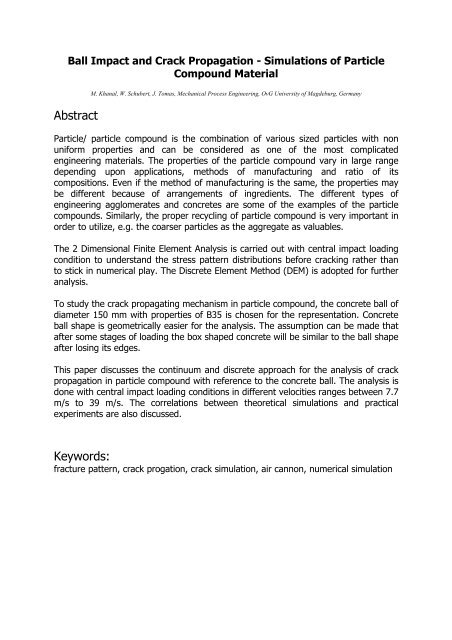
Ball Impact and Crack Propagation - Simulations of Particle<br />
Compound Material<br />
<strong>Abstract</strong><br />
M. Khanal, W. Schubert, J. Tomas, Mechanical Process Engineering, OvG University of Magdeburg, Germany<br />
Particle/ particle compound is the combination of various sized particles with non<br />
uniform properties and can be considered as one of the most complicated<br />
engineering materials. The properties of the particle compound vary in large range<br />
depending upon applications, methods of manufacturing and ratio of its<br />
compositions. Even if the method of manufacturing is the same, the properties may<br />
be different because of arrangements of ingredients. The different types of<br />
engineering agglomerates and concretes are some of the examples of the particle<br />
compounds. Similarly, the proper recycling of particle compound is very important in<br />
order to utilize, e.g. the coarser particles as the aggregate as valuables.<br />
The 2 Dimensional Finite Element Analysis is carried out with central impact loading<br />
condition to understand the stress pattern distributions before cracking rather than<br />
to stick in numerical play. The Discrete Element Method (DEM) is adopted for further<br />
analysis.<br />
To study the crack propagating mechanism in particle compound, the concrete ball of<br />
diameter 150 mm with properties of B35 is chosen for the representation. Concrete<br />
ball shape is geometrically easier for the analysis. The assumption can be made that<br />
after some stages of loading the box shaped concrete will be similar to the ball shape<br />
after losing its edges.<br />
This paper discusses the continuum and discrete approach for the analysis of crack<br />
propagation in particle compound with reference to the concrete ball. The analysis is<br />
done with central impact loading conditions in different velocities ranges between 7.7<br />
m/s to 39 m/s. The correlations between theoretical simulations and practical<br />
experiments are also discussed.<br />
<strong>Keywords</strong>:<br />
fracture pattern, crack progation, crack simulation, air cannon, numerical simulation
Introduction<br />
The aim of this research is to study the crack initiation and propagation in the<br />
building materials of spherical model like concrete ball while subjected to impact. The<br />
efficient way of cracking allows to get the valuable aggregates as the recycled<br />
products. In Germany in 1995, the annual occurance of building rubble was about 30<br />
Mt [1]. Most of the recycling products are still used as low quality materials. To<br />
produce the high quality products from recycling with the minimum of same product<br />
quality as the primary materials had, the efficient method must be adopted. The<br />
crack initiation and propagation in the concrete ball was dealt in the paper by Tomas<br />
et. al. [2]. Different research papers are available in the investigations of liberation of<br />
aggregate from the matrix [3,4] though the model material is different than the<br />
concrete ball. Single particle crushing experiments were done to investigate whether<br />
impact, double impact or compression stressing is more suitable for efficient cracking<br />
to get the better utilization of the valuables from the comparitively cheaper matrix.<br />
Spheres with only a diameter of 10 mm consisiting of sand particles embedded in<br />
hardened cement paste were used as a mineral model material by Kiss and Kiss et.<br />
al. [3,4]. Arbiter et. al. [5] produced spheres - a mixture of flint-shot sand particles<br />
and high early strength cement and water – with a diameter of 74 to 124 mm for<br />
free fall tests with stressing velocity of only up to 7.6 m/s. The goal of this was<br />
mainly to observe the crack formation and fracture patters.<br />
All these specimens used do not correspond to a real concrete composition in civil<br />
engineering [6]. The stressing conditions in recycling practice [7] are also quite<br />
different from it. It is shown from Schubert [8] that if the feed is stressed by impact<br />
or double impact, the material has a higher fracture probability than for compression<br />
stressing.<br />
Though, literatures are available for cracking in concrete structures with the<br />
application of finite element analysis, very few of these papers deal with the crack<br />
initiation and propagation in the concrete sphere when its subjected to impact. The<br />
cracking in the spherical model materials are carried out mainly in engineering<br />
agglomerates rather than in the concrete material. The concrete is also considered as<br />
the particle compound material like other engineering agglomerates. The cracking<br />
phenomena is different in sphere as compared to other regular structures in impact.<br />
The stresses for the elasto-viscoplastic conditions with FEM simulations for the<br />
sphere was investigated by Kienzler and Baudendistel [8]. But many literatures are<br />
available with the DEM simulations for the similar case of agglomerates. The DEM<br />
simulation for the impact breakage of spherical agglomerates were carried out by<br />
Kafui and Thornton [9] and Thornton et. al. [10, 11]. Mishra et. al. [12] shows the<br />
the different parameters influencing the breakage of agglomerates in impaction.<br />
Similarly, the solid particle failure under normal and oblique impact in aluminium<br />
oxide of diameter 5.15 mm was studied by Salman and et.al. [13]. The impact and<br />
compression tests for the soda lime glass spheres of diameter range 0.4-12.7 mm<br />
was presented by Salman and et. al. [14]. With DEM simulation the effect of impact<br />
angle on the breakage of agglomerates was carried out by Moreno and et. al. [15].<br />
Becauseof material heterogenity, it is noted that the deformation and fracture of
cncrete is associated with very complicated failures, as characterized by initiation,<br />
propagation and coalescence of microcracks [16,17].<br />
Numerical Simulations<br />
The initiation of the crack can be considered as the effect of stresses generated<br />
inside the concrete ball. Hence, the study of stresses inside the ball will provide the<br />
insight to the crack initiation and propagation. The best way to analyse the<br />
generation and distribution of stresses during impact in the concrete ball is through<br />
the continuum approach. The 2 Dimensional continuum analysis is carried out with<br />
central impact loading condition to understand the stress pattern distributions before<br />
cracking rather than to stick in numerical play. In reality, the continuum approach is<br />
not suitable for the analysis of particle compound as continuum theory assumes the<br />
material as continuous, homegeneous and isotropic which are totally inapplicable<br />
with particle compound. However, the continuum analysis is done with finite element<br />
analysis software called ANSYS.<br />
For the ANSYS model, a 2 Dimensional concrete ball of radius 150 mm is allowed to<br />
impinge on the target by the velocity of 50 m/s. The ball has 825 number of<br />
plane182 type elements. The contact is surface to surface contact. Elastic modulus is<br />
15 kN/mm 2 , density is 2382 kg/m 3 , poission’s ration is 0.28. The model material is<br />
assumed to have the stress-strain relationship as shown in figure 1.<br />
To understand the stress pattern distribution inside the concrete ball, the single<br />
velocity, 50 m/s, impaction is sufficient. Hence, only one impact velocity is mentioned<br />
for the continuum analysis, here, in this report as with the same parameters with<br />
only change in velocities causes the change in numerical value of the stresses rather<br />
than the stress patterns.<br />
Figure 1. shows the assumed material type for the FEA for ball.
Figure 2. shows the mess of the half concrete ball and the stress distribution in<br />
impinging direction, i.e. in Y direction.<br />
Figure 3. shows the Major principal stress distribution..<br />
Figure 4. shows the displacement in impinging direction, i.e. in Y direction.<br />
Y<br />
Y<br />
Y<br />
X<br />
X<br />
X
Figure 2 shows the maximum compressive stress is generated at the bottom of the<br />
ball and the dark coloured zone beside the cone shows the tesioned region. Initially,<br />
the stress waves are propagated from the first contact zone and moves towards the<br />
top of the ball, low stressed zone, as a result different stressed zones are built up in<br />
the system.<br />
Figure 3 shows the first pricipal stress developed during the impaction. It is clear<br />
from the figure that, in the cone shape boundary between light coloured and dark<br />
coloured zone has the transition between compressive to tensile stress. Hence, this<br />
region can have dominant effect for the crack generation.<br />
Figure 4 shows the displacement in the impenging direction. The zones which are<br />
nearer to the contact area has less displaced as compared to the farther zones,<br />
which is a normal expectation during the impact of any ball.<br />
In the stress figures, figure 2 and 3, there is more disturbances in the impacted<br />
zone, which is similar to the shape of cone or half ellipse. From this, it can be<br />
guessed that, this is the point where there will be first disturbance while impacting<br />
and hence, crack should first appeared in this region in more or less as the shape of<br />
the disturbed region, which is valid and can be seen in DEM simulation.<br />
After getting the idea of stress pattern distribution through continuum approach, the<br />
next step is followed with Discrete Element Analysis. The limitations posed by<br />
continuum analysis during assumptions are freed in Discrete Element Analysis.<br />
Discrete Element Method (DEM) treats the particle compound as the constituents of<br />
different individual small balls as the particles. In Discrete Element Method all the<br />
consituents are considered as distinct element and simple law of motion and contact<br />
law are applied to each element. The DEM is simulated through the ITASCA<br />
software[18], which considers each element as rigid ball having own stiffnesses. The<br />
Discrete Element Method allows us to visualise and track the crack propagation.<br />
The DEM model is considered to be constituents of gravel as large particles and sand<br />
as small particles and bonded with hardened cement paste. The 962 small particles<br />
having 1 mm radius are mixed with, 38 big particles, radii of 4 to 6 mm with<br />
gaussain distributions of large particles. The larger particles have normal and shear<br />
stiffness of 1x10 10 N/m and density of 2870 kg/m 3 whereas the smaller particles have<br />
the stiffness of 1x10 7 N/m with density 1790 kg/m 3 . The normal strength and shear<br />
strength of the model are 4.1 MPa. The parallel bond normal stiffness and shear<br />
stiffness are 1x10 11 N/m 2 and 6.3x10 10 N/m 2 respectively. The gravity is also allowed<br />
to act in balls during simulation. The defult time step calculation is adopted. The<br />
model is projected with the different predefined velocities. The linear spring mass<br />
contact model is chosen.<br />
Since, the ITASCA DEM[18] uses the micro properties for the modelling, its very<br />
difficult to get the exact micro properties, though the predefined equations are also<br />
available. For this concrete case, these predefined equations don’t work as per<br />
requirements. Hence, the next, trial and error method is adopted to find out the<br />
resonable micro properties.
The DEM simulation with different velocities are shown in the figures.<br />
Figure 5 a<br />
Figure 5 a shows the DEM model of the concrete ball<br />
Figure 5 b<br />
Figure 5 b shows the tension field present inside the modeled concrete ball with dark<br />
in colour and gray colour shows compression.<br />
Figure 5 shows tentative arrangement of the hardened cement paste and gravels.<br />
The bigger balls represent gravels where the smaller represents the sand. They are<br />
bonded together with hardened cement paste.<br />
The concrete ball has made to strike on the target plate with different velocities and<br />
the corresponding crack patters are shown in the figures 9 to 11 with their respective<br />
comparsion with the experimental crack pattern. The comparitive studies of DEM<br />
simulated crack and experimental crack are similar in nature with almost the same<br />
path followed in both the cases.
c<br />
a<br />
Figure 6 shows the simulation of the concrete ball fractured after impaction with<br />
velocity of a. 7.7 m/s, b. 21 m/s and c. 39 m/s<br />
l, kN<br />
al<br />
w<br />
se at<br />
on<br />
sp<br />
e re<br />
rc<br />
Fo<br />
450<br />
400<br />
350<br />
300<br />
250<br />
200<br />
150<br />
100<br />
50<br />
0<br />
7.7 m/s<br />
21 m/s<br />
39 m/s<br />
0 0.5 1 1.5 2 2.5<br />
Time, milliseconds<br />
Figure 7 shows the force experienced by the wall during impaction in DEM simulation<br />
b<br />
3
The force experienced by wall during impaction by DEM simulation is shown in the<br />
figure 7. It can be seen from the figure that almost the crack is initiated at the same<br />
force, which is shown by the first small peaks for different velocity in the graph. The<br />
rise in peak shows the forced gain by the ball because of applied velocity and the<br />
sudden fall in peak shows the crack propagated inside the ball and the energy is<br />
consumed for generating the new surface.<br />
Experiments<br />
The impact experiments are carried out with our pneumatic cannon [2] as shown in<br />
figure 8, which works with acclerating principle by air pressure. The pneumatic<br />
cannon allows adjustment of different stressing conditions in different velocities as a<br />
function of air pressure. The test rig consits of two main parts, air pressure unit and<br />
acclerating unit. The operating principle of pneumatic cannon is as follows. Firstly,<br />
the test sample is loaded with the cartridge in the accelerating tube. The test sample<br />
may be the one which is to be crushed, generally, a concrete ball or waste materials.<br />
After loading, the accelerating tube is closed carefully and the compressor is allowed<br />
to fill the air in the pressure tank. Once, the required pressure reaches the tank, the<br />
valve is opened and immediately, the sample along with the cartridges accelerates in<br />
the tube and impinges in the target made up of strong steel alloy and crushes. All<br />
pressures and velocities are monitored simultaneously and recorded in the computer<br />
for analysis. The test rig can amounts for maximum pressure of 3 MPa with sample<br />
mass of 1 – 4 kg. The sample material can be accelerated upto 300 m/s. The<br />
crushing process can be observed through the high speed camera at 200 pictures per<br />
second.<br />
A large number of balls were impacted to get the consistent result. The concrete ball<br />
of 150 mm diameter of B35 strength category were chosen for the experiment. The<br />
generated fragments after impaction were collected in the bin as situated in the<br />
cannon at outlet side. Each ball was coloured with different colours in different sides<br />
before impaction. After, each impaction the fragmented parts were collected and<br />
assembeled according to the color. The assembeled fragmented parts are shown in<br />
figure 9 b, 10 b and 11b for different velocitiesof 7.7 m/s, 21 m/s and 39 m/s<br />
respectively. It is clear from the figure that, every assembeled ball has lost its conical<br />
or semi elleptical shape on the impacted side. This shows the disturbed region has<br />
the conical shape as predicted by continuum method. The increase in impact velocity<br />
causes the increase in contact diamter with the target and expand in the cone like<br />
region. This conical lost region is the one, called cone of fines. The meridian cracks<br />
and secondary craks are also seen in the figure. The meridian cracks move in the<br />
direction of the impact like orange pieces. The secondary cracks are not in parallel to<br />
the meridian craks. Generally, the secondary craks are perpendicular to the meridian<br />
craks but not all secondary cracks. The impact speed causes the cone of fines to<br />
expand more and lose in remaining cone. Hence, it can be seen that as the cone of<br />
fines increases the remainiing cone decreases.<br />
The current analysis is done with central impact loading conditions in different<br />
velocities ranges between 6 m/s to 50 m/s with sample mass of 4 kg. The concrete<br />
balls are of B 35 model concrete having compressive strength 35 N/mm 2 , water
cement ratio 0.5, aggregate cement ratio 5:1, storage time greater than 180 days,<br />
150 days from it wet stored [6].<br />
counter-mass<br />
m = 4.5 t<br />
acceleration tube<br />
impact space<br />
loading device<br />
10.20 m<br />
fast release valve<br />
Figure 8 shows the assembly of pneumatic cannon<br />
compressor<br />
V = 2000 l<br />
pressure tank<br />
Results and Discussion<br />
In the figures, 2 and 3, it can be seen that, there are more disturbances in the<br />
impacted zone, which is similar to the shape of cone or half ellipse. From this, it can<br />
be guessed that, this is the point where there will be first disturbance while<br />
impacting and hence, crack should first appeared in this region in more or less as<br />
the shape of the disturbed region. This can be seen valid with the help of Discrete<br />
Element Method.<br />
When the stress generated by the impaction at the maximum possible contact<br />
circumference is greater or sufficient than the material absolute difference in values<br />
between the tensile and compressive strength the contact deformation initiates the<br />
small circular crack of radius of impaction and small meridian cracks. The tension<br />
region shows in the boundary of the contact diameter initials the crack. Again as the<br />
crack goes inside and if the stresses are still greater than the material stresses (as<br />
the binding force between the materials) of the materials at the weakest points, the<br />
crack propagates inside the ball with further meridian cracks, as shown in figure 12<br />
by Tomas and et al. If the weakest points lie perpendicular to the meridian cracks<br />
then the secondary cracks are generated. The circular crack is initiated from the<br />
point where there is maximum change in stress values from tension to compression.<br />
Once, the crack is initiated through the impacted edges, again, the crack will follow<br />
3.40 m 2.40 m
the path to form the wedge shaped fragment and shows the sharp cutting edge<br />
effect. The crack follows the weakest point of the concrete ball to make the elleptical<br />
or conical region in the ball from the side of impaction. The sharp point tip of the<br />
fragment further penitrates inside the remainig cone of the ball. In this process the<br />
share stress will also be generated in the interface of two cones in opposite direction<br />
of the enhancement of the crack. During the propagation of circular crack inside the<br />
concrete ball, the meridian crack will also propagate and unbalanced stresses will be<br />
generated which introduces the secondary cracks. The intensity of occurance of this<br />
phenomenon depends upon the stress generated inside the ball during impaction<br />
which governs by the impact velocity of the ball.<br />
The simulation from the Discrete Element method shows the crack propagation path<br />
followed the same path as predicted by finite element method in the initial stage. As<br />
the continuum method doesn’t allow the calculation in discontiniuos region, hence,<br />
the propagation of crack can be predicted by discrete element method. The results<br />
obtained from the Discrete Element Simulation is compared with the practicle results<br />
and shown in figures 9 to 11. The fragments from the simulated results show the<br />
almost same type of fragments as found from the experiment. It can be seen that<br />
figure 6 a, b, c show the same nature of cracking during impaction.<br />
Figure 9 a and b show the crack pattern observed during DEM simulation and<br />
experimental simulation respectively with velocity 7.7 m/s.
Figure 10 a<br />
Figure 10 b<br />
Figure 10 a and b show the crack pattern observed during DEM simulation and<br />
experimental simulation respectively with velocity 21 m/s.<br />
Figure 11 a<br />
Figure 11 b<br />
Figure 10 a and b show the crack pattern observed during DEM simulation and<br />
experimental simulation respectively with velocity 39 m/s.<br />
Figures 9, 10, 11 show the fracture patterns follow the identical path during<br />
simulation and experiments.
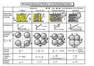
Figures 12 shows the fracture types as proposed by Tomas and et al [2].<br />
Conclusion<br />
The DEM simulation shows the similar cone type disturbed region as shown by FEM<br />
for the crack initiation. Depending upon the impact velocities the cracks are<br />
furthering inside along with meridian cracks and secondary cracks. The diameter of<br />
the contact region depends upon the impact velocities.<br />
Acknowlegdements<br />
The authors would like to thank German Research Foundation for the financial<br />
support.<br />
References<br />
[1] K. Seick, Entwicklung des Abfallaufkommens und er Abfallzusammensetzung<br />
im Land Sachsen-Anhalt, Seminar Siedlungsabfallwirtshaft, Universität<br />
Magdeburg, 1996.<br />
[2] J. Tomas, M. Schreier, T. Gröger, S. Ehlers, Impact crushing of concrete for<br />
liberation and recycling, Powder Technology 105(1999), 39-51<br />
[3] L. Kiss, Vergleich der Prall- und Druckzerkleinerung eines zweikomponentigen,<br />
mineralischen Modellstoffes, Dissertation, Universität Karlsruhe, 1979<br />
[4] L. Kiss, K. Schnört, Aufschlußzerkleinerung eines zweikomponentigen<br />
modellstoffes unter einzelkornbeanspruchung durch druck-und<br />
prallbeanspruchung [Liberation of two component materail bz single particle<br />
compression and impact crushing]. Aufbereit.-Tech.30(5)(1980)223-230<br />
[5] N. Arbiter, C. C. Harris, G. A. Stamboltzis, Single fracture of brittle spheres,<br />
Soc. Min. Eng. AIME, Trans. 244 (1969) 118-133.<br />
[6] B. Dora, H. Budelmann, Baustoffeigenschaften, Zwischenbericht des<br />
Sonderforschungsbereiches 385, Baustoffrecycling, Magdeburg, 1996, 251-281.<br />
[7] J. Tomas, M. Schreier, S. Ehlers, Aufschlusszerkleinerung von Beton,<br />
Proceedings of 7th Intern. Building Material Recycling Forum, Interlaken, 1996,<br />
16-36.<br />
[8] H. Schubert, Zur Energieausnutzung bei Zerkleinerungsprozessen, Aufbereit. –<br />
Tech. 34 (10) (1993) 495-505.<br />
[9] K. D. Kafui, C. Thornton, Numerical simulations of impact breakage of a<br />
spherical crystalline agglomerate, Powder Technology 109 (2000) 113-132<br />
[10] C. Thornton, M. T. Ciomocos, M. J. Adams, Numerical simulations of<br />
l i b k P d T h l 105 (1999) 74 82
agglomerate impact breakage, Powder Technology 105 (1999) 74-82.<br />
[11] C. Thornton, K. K. Yin, M. J Adams, Numerical simulations of impact fracture<br />
and fragmentation of agglomerates, J. Phys. D: Appl. Phys. 29 (1996) 424-435<br />
[12] B. K. Mishra, C. Thornton, Impact breakage of a particle agglomerates, Int. J.<br />
Miner. Process. 61 (2001) 225-239.<br />
[13] A. D. Salman, D. A. Gorham, A. Verba, A study of solid particle failure under<br />
normal and oblique impact, Wear 186-187 (1995) 92-98.<br />
[14] A. D. Salman, D. A. Gorham, The fracture of glass spheres, Powder<br />
Technology 107 (2000) 179-185.<br />
[15] R. Moreno, M. Gadhiri, S. J. Antony, Effect of impact angle onthe breakage of<br />
agglomerates: a numerical study using DEM, Powder Technology 130 (2003)<br />
132-137.<br />
[16] Chandra S, Berntsson L., Interdependence of microstructure and strength of<br />
structural lighweight aggregate concrete. Cement and concrete composites,<br />
1992 (14), 239-248<br />
[17] Romstad KM, Taylor MA, Herrmann LR., Numerical biaxial characterization for<br />
concrete, Journal of Engineering Mechanics Division ASCE 1974, 100 (5), 935-<br />
948<br />
[18] Manual of PFC2D, ITASCA