MDC SERIES - Blue Giant Equipment Corporation
MDC SERIES - Blue Giant Equipment Corporation
MDC SERIES - Blue Giant Equipment Corporation

You also want an ePaper? Increase the reach of your titles
YUMPU automatically turns print PDFs into web optimized ePapers that Google loves.
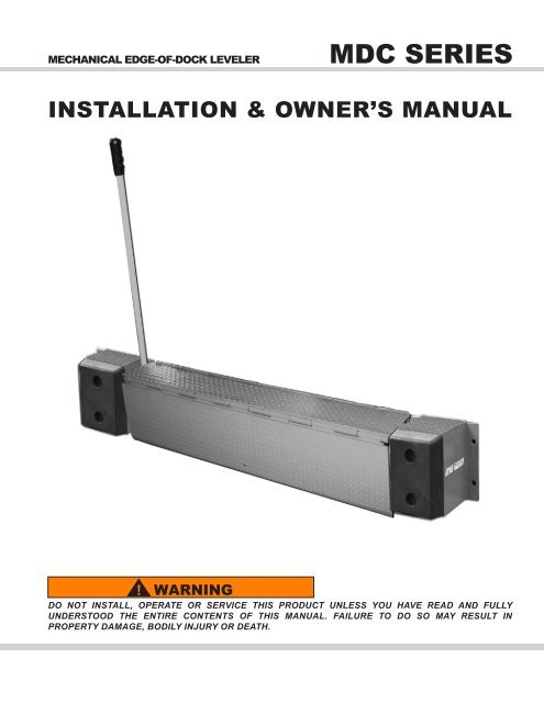
MECHANICAL EDGE-OF-DOCK LEVELER <strong>MDC</strong> <strong>SERIES</strong><br />
INSTALLATION & OWNER’S MANUAL<br />
! WARNING<br />
DO NOT INSTALL, OPERATE OR SERVICE THIS PRODUCT UNLESS YOU HAVE READ AND FULLY<br />
UNDERSTOOD THE ENTIRE CONTENTS OF THIS MANUAL. FAILURE TO DO SO MAY RESULT IN<br />
PROPERTY DAMAGE, BODILY INJURY OR DEATH.
TABLE OF CONTENTS<br />
Table of Contents ............................................................................................3<br />
Check Shipment Notice ..................................................................................3<br />
Owner’s Record of Purchase ..........................................................................3<br />
Safety .......................................................................................................... 4-5<br />
Installation Instructions ............................................................................... 7-8<br />
Operating Instructions ............................................................................... 9-10<br />
Maintenance ............................................................................................11-12<br />
Trouble Shooting...........................................................................................13<br />
Replacement Parts ............................................................................... ..14-15<br />
Warranty ................................................................................................. 18-19<br />
OWNER’S PURCHASE RECORD<br />
Dealer: Date in Service:<br />
Owner: Number of Units:<br />
Order Number: Year of Construction:<br />
Serial Numbers:<br />
CHECK SHIPMENT BEFORE INSTALLATION<br />
The leveler has been carefully checked at the manufacturer’s plant before shipment. In order to ensure that no<br />
damage has occurred during transport, the leveler should be checked upon receipt for transport damage and to ensure<br />
correct operation. Damage due to transport is to be listed on the signed copy on the freight document. The freight<br />
forwarder must be notified of any damage within 48 hours. Damaged levelers must not be put into use.<br />
<strong>Blue</strong> <strong>Giant</strong> offers a full line of dock levelers, dock safety equipment, accessories, ergonomic and scissor lift<br />
equipment, and industrial trucks. Concurrent with our continuing product improvement program, specifications are<br />
subject to change without notice. Some features illustrated may be optional in certain market areas. Visit<br />
www.<strong>Blue</strong><strong>Giant</strong>.com for latest product information.<br />
MD-CM 01/02/2008 (Part # 411-253-0)<br />
3
4<br />
1. Do not install this leveler, operate and/or service unless<br />
you have been trained and authorized to do so.<br />
2. Do not install, operate and/or service this leveler until<br />
you have read and understood all of the safety information<br />
and instructions contained herein and on the leveler.<br />
3. Do not operate this leveler until you have checked its<br />
condition. Report the need for leveler repairs to your<br />
supervisor immediately and do not operate leveler until<br />
repairs are made. Neglect may cause a minor repair to<br />
become a major service problem and cause the leveler to<br />
become unsafe.<br />
4. Do not work under or around leveler being installed<br />
without first placing adequate barriers to positively prevent<br />
vehicle traffic from entering the work area.<br />
5. All electrical wiring, hook-up, repair and troubleshooting<br />
must be performed by qualified service personnel.<br />
All wiring, hook-up and repairs must be made to meet all<br />
applicable codes. Before doing any electrical work, make<br />
certain the power is disconnected and properly tagged<br />
and / or locked out.<br />
6. Before performing any maintenance, secure dock leveler<br />
properly.<br />
7. Do not load leveler beyond capacity shown on serial<br />
name plate on leveler.<br />
8. Stay clear of dock leveler and vehicle when vehicle is<br />
backing in or leaving dock area.<br />
9. Secure vehicle by chocking vehicle wheels or use of<br />
vehicle restraint, as detailed by OSHA, before operating<br />
dock leveler.<br />
10. Do not use or move the dock leveler if anyone is<br />
under, in front and/or on dock leveler.<br />
11. Keep hands and feet clear of dock leveler pinch points<br />
SAFETY PROCEDURES<br />
INTRODUCTION<br />
The following is intended to be a quick reference to some of the important procedures to follow while using the MD-CM Series Edge-<br />
Of-Dock Leveler. It is not intended to cover, or suggest that it does cover, all procedures required to be followed to ensure safe operation.<br />
Operators should be aware of and abide by all workplace safety regulations that may apply to the operation of the MD-CM<br />
Series Edge-Of-Dock Leveler. These laws and regulations include but are not limited to:<br />
- Occupational Safety and Health Act (USA).<br />
- Occupational Safety and Health Acts for Individual States (USA).<br />
- Canadian Material Handling Regulations.<br />
For further information on these regulations and / or industry standards that may apply to this equipment, please contact:<br />
American National Standards Institute (ANSI)<br />
1430 Broadway<br />
New York, NY 10018<br />
(212) 642-4900<br />
! WARNING<br />
EXCLUSION OF LIABILITY<br />
at all times. Never use hands to lift dock ramp and/or lip<br />
onto vehicle or to store dock leveler.<br />
12. Never try to lift or move any part of the Dock Leveler<br />
without using the Comfort grip handle.<br />
13. Do not drive on leveler unless lip is securely on<br />
vehicle bed and has a minimum of 4” (100mm) projection<br />
on vehicle bed.<br />
14. Do not exceed 3 mph when driving over dock leveler.<br />
15. Do not drive over edges of the leveler and / or dock<br />
bumper blocks (bumpers blocks are not structural).<br />
16. Do not leave equipment or material unattended on leveler.<br />
17. Do not leave the leveler unattended in the deployed<br />
position.<br />
18. Do not use fork truck or any other material handling<br />
equipment to lower leveler ramp.<br />
19. Never attempt to perform repairs. Always defer repairs<br />
to a qualified service technician.<br />
20. Do wear safety equipment as required.<br />
21. Workplace practical guide for safe use of this<br />
product may restrict the use of any substance that may<br />
compromise or impair safe operational use.<br />
This manual is intended to be readily available. Keep it<br />
near the leveler as a ready reference for anyone who may<br />
operate or service it. If the leveler being operated is not<br />
equipped with a manual, request to obtain one and have<br />
it located near the leveler.<br />
An authorized dealer or distributor is readily available to<br />
answer questions about leveler operation and maintenance<br />
and will provide additional information should it<br />
be required.<br />
The manufacturer assumes no liability for damage or injury to persons or property which have occurred as a result of defects or faults in the dock<br />
levelers delivered or due to incorrect use. The manufacturer also assumes no liability for lost profits, operating down times, or similar indirect losses<br />
which the buyer has incurred. Damage to third parties, irrespective of its nature, is not subject to compensation.<br />
The operating instructions are not subject to notification of amendment. The descriptions and illustrations included in our operating instructions and<br />
replacement parts list are not binding. In the interests of continuing product development, we reserve the right to make any changes at any time to<br />
the product construction, structure, components and accessories, concurrent with our continuing product improvement program, specifications are<br />
subject to change without notice. Please contact <strong>Blue</strong> <strong>Giant</strong> for latest product information, or visit our web site www.<strong>Blue</strong><strong>Giant</strong>.com for the most<br />
current product information.<br />
MD-CM 01/02/2008 (Part # 411-253-0)
Safety Signs and Safety Messages<br />
This message indicates an imminently hazardous<br />
situation which, if not avoided, will result in death or<br />
serious injury.<br />
! CAUTION<br />
This message indicates a potentially hazardous situation<br />
which, if not avoided, may result in minor or moderate<br />
injury.<br />
SAFETY WARNINGS<br />
Improper operation can cause accidents. Don’t take chances with incorrect or damaged equipment. Read and understand the procedures<br />
for safe operation and maintenance outlined in this manual. Don’t hesitate to ask for help.<br />
Stay alert! Follow safety rules, regulations, and procedures. Avoid accidents by recognizing dangerous procedures or situations<br />
before they occur.<br />
Safety signs and messages are placed in this manual to provide instructions and identify specific areas where potential hazards exist<br />
and special precautions should be taken. Know and understand the meaning of these instructions, signs, and messages. Damage<br />
to the equipment, death, or serious injury to you or other persons may result if these messages are not followed. If warning decals<br />
are damaged, they must be replaced. Contact your Distributor for replacements.<br />
MD-CM 01/02/2008 (Part # 411-253-0)<br />
! DANGER ! WARNING<br />
This message indicates a potentially hazardous situation<br />
which, if not avoided, could result in death or<br />
serious injury.<br />
IMPORTANT<br />
This message is used when special precautions<br />
should be taken to ensure a correct action or to avoid<br />
damage to or malfunction of the equipment and/or a<br />
component.<br />
5
6<br />
INSTALLATION INSTRUCTIONS<br />
MD-CM 01/02/2008 (Part # 411-253-0)
! WARNING<br />
Do not install, operate and/or service this leveler until<br />
you have read and understood all of the safety information<br />
and instructions contained herein and on the<br />
leveler.<br />
Do not work under or around leveler being installed<br />
without first placing adequate barriers to positively<br />
prevent vehicle traffic from entering the work area.<br />
Keep hands and feet clear of dock leveler pinch<br />
points<br />
Mechanical Edge-Of-Dock Installation<br />
1. Inspect the loading dock curb angle and verify that it is firmly<br />
embedded and anchored in the concrete and is minimum 3”<br />
x 8” x 1/4” (75 x 75 x 6mm) steel. If there is no curb angle, if<br />
anchoring or embedding is questionable, or is not of minimum<br />
size specified, proceed with advise installation mounting types<br />
per page 6.<br />
! WARNING<br />
The EOD leveler must be welded to a firmly embedded<br />
steel channel or other dock steel as described in the<br />
installation instructions. Do not attempt to use only<br />
bolts or anchors to attach the dock leveler to the concrete.<br />
Use caution when removing strapping from the EOD<br />
leveler. Keep hands clear of pinch points and wear<br />
appropriate safety attire - glasses, gloves and work<br />
boots.<br />
2. Remove strapping from the EOD and discard all shipping<br />
material.<br />
! WARNING<br />
Use caution when lifting or moving the EOD leveler. Do<br />
not attempt to lift without suitable hoisting equipment<br />
capable of lifting as much as 600 lbs.<br />
4. Position the back frame so that the top of the frame is 5/32”<br />
(4mm) below the level of the top of the curb angle (plus 1/8”<br />
(4mm), minus 0” (4mm)). Ensure top of frame is parallel with<br />
the top of the curb angle.<br />
5. Tack weld top of back frame securely to curb angle.<br />
6. Ensure that the back frame is firmly against curb angle or<br />
dock face concrete and plug-weld the back frame to the curb<br />
angle at the four circular holes in the frame. If curb angle does<br />
not overlap these holes, use the back plate as a template and<br />
drill four holes 5/8” dia. x 6” (15mm x 150mm) deep, in the<br />
dock face concrete. Clean out holes and insert and permanently<br />
install appropriate concrete wedge anchors. (See page<br />
4). Tighten enough to secure the Back Frame.<br />
7. Finish weld the top of the back frame to the curb angle.<br />
Weld 1/4” x 5” (6mm x 125mm) long welds on both ends of<br />
the back frame. Repeat the 1/4” welds on 9” (225mm) centers<br />
MD-CM 01/02/2008 (Part # 411-253-0)<br />
INSTALLATION INSTRUCTIONS<br />
across the full length of the back frame.<br />
8. Vertical weld both ends of back frame to curb angle, full<br />
length of vertical contact. Tighten the wedge anchor nuts securely.<br />
9. Position the left-hand bumper bracket (as viewed when<br />
standing on the driveway in front of the Dock Leveler) so<br />
that there is 1/2” (13mm) clearance between the bracket side<br />
and the comfort grip handle pocket, and the bracket is level<br />
with the top of the curb angle. Weld all horizontal and vertical<br />
contact areas between bracket and curb angle and plug<br />
weld mounting holes that overlap curb angle. Install concrete<br />
wedge anchors 5/8” x 6” (15mm x 150mm) in mounting holes<br />
that are not welded.<br />
10. Position the right-hand bumper bracket so that there is a<br />
1/2” (13mm) clearance between the bracket and the dock leveler<br />
deck plate. Weld all horizontal and vertical contact areas<br />
between bracket and curb angle and plug weld mounting holes<br />
that overlap curb angle. Install concrete wedge anchors 5/8” x<br />
6” (15mm x 150mm) in mounting holes that are not welded.<br />
11. Install the comfort grip handle in the pocket on the left side<br />
of the deck. To do so, remove the bolt from the bottom of<br />
the handle, insert handle through pocket, then re-install bolt<br />
through hole in handle.<br />
12. Lubricate all pivot points using SAE30 motor oil or equivalent.<br />
Installation Inspection<br />
1. Clean up the entire work area and apply touch-up paint to<br />
all welds, scratches and burns.<br />
2. Ensure all concrete wedge anchors have been securely<br />
tightened.<br />
! WARNING<br />
Read and understand this entire manual prior to operating.<br />
3. Test operate the unit through several full cycles of operation.<br />
Refer to: Operating Procedures. If problems are noted,<br />
See Section on Troubleshooting.<br />
4. Leave these Instructions for use by owner.<br />
7
8” Pour-In Channel<br />
Figure 2 : 8” Pour-In Channel Arrangement.<br />
• Must be poured-in with dock concrete.<br />
• 8” Structural channel minimum, 11.5 lb/ft.<br />
• Weld-on curb angle concrete anchors to be minimum 5/8” x 6” long<br />
located on 12” centers with one anchor 3” from each end.<br />
Optional Approach Ramp Installation<br />
WELD<br />
CURB<br />
ANGLE<br />
ANCHOR<br />
8” POUR-IN CHANNEL<br />
RAMP<br />
Figure 3 : Approach Ramp Arrangement<br />
• Position ramp as illustrated. Outside edge of ramp flush with out-<br />
side edge of curb angle.<br />
• Tack-weld ramp to curb angle.<br />
• Drill 3/4” dia. holes using ramp as a template. Insert 5/8” expansion<br />
sleeves (010-116). Install and tighten 5/8” x 1-1/2” button-head<br />
bolts (010-117) using 3/8” Allen key wrench.<br />
• Weld the ramp to the curb angle as illustrated. 1/4” x 5” welds on<br />
9” centers.<br />
INSTALLATION MOUNTING TYPES<br />
ANCHOR<br />
EXPANSION<br />
SLEEVE<br />
BUTTON<br />
HEAD<br />
BOLT<br />
One Piece Angle Plate<br />
Face Plate Types - For<br />
use on existing docks with<br />
no curb steel<br />
Figure 4 : One Piece Angle Plate<br />
BEVELED<br />
EDGE<br />
(BY OTHERS)<br />
• 1/4” minimum plate thickness. Top plate 13” wide, face<br />
plate 10-” wide. Length to suit EOD Leveler model.<br />
• Place angle plate on existing dock as shown. Use as drill template.<br />
• Lag to sound concrete as follows:<br />
Top Plate - Drill 3/4” dia. x 3-1/2” deep holes. Insert 5/8” expansion<br />
sleeves (010-116). Install and tighten 5/8” x 1-1/2” button-head<br />
bolts (010-117) using 3/8” Allen key.<br />
Face Plate - Drill 5/8” dia x 6” deep holes. Insert 5/8” x 6” long<br />
concrete anchor wedges (010-108) and tighten.<br />
Two Piece Angle Plate<br />
Figure 5 : Two Piece Angle Plate<br />
BEVELED<br />
EDGE<br />
(BY OTHERS)<br />
• 1/4” minimum plate thickness. Top plate 13” wide, face<br />
plate 10” wide. Length to suite EOD Leveler model.<br />
• Place top plate on top of existing dock, front edge flush with<br />
dock face, full length.<br />
• Drill 3/4” dia. x 3-1/2” deep holes using plate as template.<br />
Insert 5/8” expansion sleeves (010-116). Install and tighten<br />
5/8” x 1-1/2” button-head bolts (010-117) using 3/8” Allen<br />
key wrench.<br />
• Place face plate in position as shown. Position top edge for<br />
welding and tack-weld to top plate.<br />
• Drill 5/8” dia. x 6” deep holes using plate as a template. Insert<br />
5/8” x 6” long concrete wedge anchors (010-108) and tighten.<br />
• Weld the two plates together as illustrated. 1/4” x 5” long welds on<br />
9” centers.<br />
Note : All hardware must be purchased separately as part of an optional mounting kit.<br />
Consult your local distributor/dealer for more information.<br />
8<br />
WELD<br />
MD-CM 01/02/2008 (Part # 411-253-0)
! WARNING<br />
Do not install this leveler, operate and/or service unless<br />
you have been trained and authorized to do so.<br />
Do not install, operate and/or service this leveler until<br />
you have read and understood all of the safety information<br />
and instructions contained herein and on the<br />
leveler.<br />
Do not operate this leveler until you have checked its<br />
condition. Report the need for leveler repairs to your<br />
supervisor immediately and do not operate leveler until<br />
repairs are made. Neglect may cause a minor repair<br />
to become a major service problem and cause the leveler<br />
to become unsafe.<br />
Never try to lift or move any part of the Dock Leveler<br />
without using the comfort grip handle.<br />
Keep hands and feet clear of dock leveler pinch points<br />
at all times. Never use hands to lift dock ramp and/or<br />
lip onto vehicle or to store dock leveler.<br />
Do not drive on leveler unless lip is securely on vehicle<br />
bed and has a minimum of 4” (100mm) projection<br />
on vehicle bed.<br />
Do not exceed 3 mph when driving over dock leveler.<br />
Do not drive over edges of the leveler and / or dock<br />
bumper blocks (bumpers blocks are not structural).<br />
FUNCTIONAL DESCRIPTION<br />
• The Mechanical Edge-of-Dock (EOD) Leveler is intended<br />
to be used as a bridge located between a loading dock<br />
floor surface and the rear deck upper surface of a vehicle.<br />
• The EOD Leveler upper deck plate complete with a<br />
hinged, vertically hanging lip plate is located flush with<br />
the floor surface and is permanently mounted on the outer<br />
edge of the loading dock.<br />
• The rear deck surface of a vehicle is parked and blocked<br />
in place against the dock bumpers that are integral components<br />
of the EOD Leveler, in working alignment with the<br />
EOD Leveler. An EOD Leveler used in conjunction with<br />
a Vehicle Restraint are ideal for this application. Consult<br />
your local Dealer/Distributor.<br />
• The EOD Leveler is operated by pulling back on the comfort<br />
grip handle. The hinged lip plate raises to a horizontal<br />
position as the deck is rotated up into a vertical position.<br />
As the operator pushes the comfort grip handle forward,<br />
rotating the deck forward into a horizontal position, the lip<br />
moves forward horizontally until the underside comes to<br />
rest on the deck of the vehicle.<br />
• A bridge is now formed that is supported at the building<br />
end by the dock floor and at the vehicle end by the vehicle<br />
deck.<br />
• The EOD must now be walked to insure the kicker bar is<br />
disengaged.<br />
• No other means of support is provided when in this position.<br />
•The EOD Leveler is restored to its original stored position<br />
by the operator before the vehicle is allowed to depart.<br />
MD-CM 01/02/2008 (Part # 411-253-0)<br />
OPERATING INSTRUCTIONS<br />
OPERATION (CONTACT SUPERVISOR FOR ASSISTANCE)<br />
DOCK IS AVAILABLE FOR USE<br />
1. The vehicle driver reverses the vehicle into position<br />
firmly against the dock bumper extensions.<br />
Note : The comfort grip operating handle is shown in position.<br />
2. The dock operator ensures the vehicle is blocked<br />
securely (using either a vehicle restraint and/or wheel<br />
chocks) to prevent forward creep or unexpected<br />
departure.<br />
3. The operator pulls the comfort grip operating<br />
handle backwards fully to rotate the handle to its lower<br />
position. The deck plate is past the vertical position and<br />
the lip plate is near horizontal.<br />
9
! WARNING<br />
Do not attempt to operate the EOD leveler without<br />
using the comfort grip handle.<br />
4. The operator pushes the comfort grip operating<br />
handle forward to rotate the deck plate back towards its<br />
original position.<br />
5. During this step, the lip plate will remain horizontal and<br />
extend until it comes to rest on the transport vehicle floor.<br />
The lip plate must overlap the transporter vehicle<br />
load bed by a minimum of 4” (100mm) full width.<br />
6. With the lip plate in full contact with the vehicle<br />
load bed, the loading/unloading operation can be<br />
completed.<br />
Remove the comfort grip handle, before loading<br />
and/or unloading cargo.<br />
10<br />
! WARNING<br />
IMPORTANT<br />
OPERATING INSTRUCTIONS<br />
! WARNING<br />
The vehicle should never be allowed to depart<br />
with the lip plate resting on the load bed.<br />
7. When traffic across the dock leveler has ceased<br />
the operator must return the EOD Leveler to its stored<br />
position.<br />
8. The operator raises the deck, by pulling back on the<br />
comfort grip handle, only enough to release the lip from<br />
the surface of the transporter vehicle load bed. When<br />
the lip pivots downward to a pendant position, the unit is<br />
allowed to return to stored position.<br />
9. The operator releases the vehicle restraint or<br />
removes the wheel chocks to allow the vehicle to<br />
depart. The operator then indicates to the vehicle driver<br />
that it is safe to depart.<br />
10. The comfort grip handle is then returned to the<br />
stored position. The dock is once again available for<br />
use.<br />
MD-CM 01/02/2008 (Part # 411-253-0)
! WARNING<br />
Do not work under or around the dock leveler<br />
without first placing adequate barriers to positively<br />
prevent vehicle traffic from entering the<br />
work area.<br />
Never attempt to perform repairs. Always defer<br />
repairs to a qualified service technician.<br />
Routine Servicing And Maintenance<br />
Regular maintenance and care of the equipment is<br />
very important for cost and operation efficiency and<br />
more importantly operator safety. Faulty equipment is a<br />
potential source of danger to the operator, and to other<br />
personnel working near it. As with all quality equipment,<br />
keep the equipment in good operating condition by<br />
following the recommended schedule of maintenance.<br />
Failure to do so will void the manufacturer’s warranty.<br />
DECK HINGE PIVOT POINTS<br />
MD-CM 01/02/2008 (Part # 411-253-0)<br />
MAINTENANCE<br />
GREASE FITTINGS<br />
Authorize Usage<br />
The importance of this procedure is emphasized in this<br />
manual with a brief review and later with more detailed<br />
instructions. For more information regarding authorize<br />
usage contact manufacture.<br />
Available support by dealer/distributor:<br />
• <strong>Equipment</strong> usage training and authorization<br />
• Workplace practical guide for safe use of this product<br />
• Ease of service; inspection and planned maintenance<br />
• <strong>Equipment</strong> daily inspection check list<br />
Maintenance Sequence<br />
1. Cleaning, including surrounding area.<br />
2. Visual inspection of all components.<br />
3. Lubrication as required.<br />
4. Test operate all functions.<br />
5. Adjustments if required.<br />
Figure 6 : Mechanical Edge-Of-Dock Leveler - Lubrication Points<br />
KICKER BAR<br />
ADJUSTMENT<br />
NUT<br />
11
12<br />
1<br />
A<br />
A<br />
MAINTENANCE<br />
2<br />
DIM A<br />
SECTION A-A<br />
SCALE 1 : 4<br />
Note: Dim. A is for general reference only.<br />
MD-CM 01/02/2008 (Part # 411-253-0)
TROUBLE SHOOTING<br />
Problem Cause and Solution<br />
EOD Leveler requires more effort than usual when raised<br />
to position.<br />
When pulling the comfort grip handle up to raise the<br />
EOD into position, the lip does not remain horizontal as<br />
deck is pushed forward.<br />
Lip does not deploy onto vehicle bed.<br />
Lip Kicker Bar does not swing down to release position<br />
when unit is lowered onto vehicle bed.<br />
• Adjustment of Extension Springs required<br />
- Increase tension of both springs equally<br />
Note: Increase spring tension only enough to provide<br />
usual lifting effort<br />
• Lip Kicker Bar did not swing into position over fixed<br />
block<br />
• Adjust adjusting screw outward to raise lip and allow<br />
lock bar to swing into position over block<br />
• Lip Kicker bar binding at mounting bracket. Bar must<br />
swing freely<br />
• Lubricate or straighten<br />
• Kicker bar is binding in its mounting bracket<br />
- Lubricate or straighten. Bar must swing freely<br />
Lip remains partially extended after vehicle drives away. • Lip hinge has seized up<br />
- Free up and lubricate<br />
Lip hits back of vehicle first.<br />
MD-CM 01/02/2008 (Part # 411-253-0)<br />
• Adjust adjusting screw to provide clearance<br />
See page 12 & 13 for Component Identification<br />
• Bumper worn out; replace Bumper.<br />
13
14<br />
5<br />
13 14 15 20<br />
REPLACEMENT PARTS<br />
10 19 17 21 2 3 1<br />
7<br />
6<br />
16 17<br />
MECHANICAL <strong>MDC</strong> <strong>SERIES</strong>: ALL MODELS<br />
11<br />
12<br />
18<br />
8<br />
9<br />
4<br />
MD-CM 01/02/2008 (Part # 411-253-0)
AVAILABLE REPLACEMENT PARTS<br />
ITEM QTY PART NUMBER GENERAL DESCRIPTION SPECIFIC DESCRIPTION<br />
1 1 017-083 TENSION SPRING ALL MODELS EXCEPT <strong>MDC</strong>6620<br />
017-061 TENSION SPRING <strong>MDC</strong>6620M (15" & 17" LIP)<br />
2 1 017-083 TENSION SPRING <strong>MDC</strong>7225M (15" & 17" LIP)<br />
<strong>MDC</strong>7230M (15" & 17" LIP)<br />
<strong>MDC</strong>7825M (15" & 17" LIP)<br />
<strong>MDC</strong>7830M (15" & 17" LIP)<br />
017-061 TENSION SPRING <strong>MDC</strong>6620M (15" & 17" LIP)<br />
<strong>MDC</strong>6625M (15" & 17" LIP)<br />
<strong>MDC</strong>6630M (15" & 17" LIP)<br />
<strong>MDC</strong>7220M (15" & 17" LIP)<br />
3 3 200-01573 EXTENSION BAR ALL MODELS<br />
4 1 252-0024-2 KICKER BAR ASSY. ALL MODELS<br />
5 1 010-067 CAP SCREW ALL MODELS<br />
6 1 200-01585-1 HANDLE TUBING ALL MODELS<br />
7 1 200-01570 TUBE CAP ALL MODELS<br />
8 1 250-0001 PIN ALL MODELS<br />
9 2 013-020 SPRING PIN ALL MODELS<br />
10 2 110-886 BUMPER ALL MODELS<br />
11 2 300-170 CLEVIS PIN ALL MODELS<br />
12 2 013-006 SPRING PIN ALL MODELS<br />
13 4 010-086 CAP SCREW ALL MODELS<br />
14 4 012-214 WASHER ALL MODELS<br />
15 4 011-510 NUT ALL MODELS<br />
16 2 010-083 CAP SCREW ALL MODELS<br />
17 4 105-882 FLAT WASHER ALL MODELS<br />
18 3 011-552 LOCK NUT ALL MODELS<br />
19 1 200-01572 SPRING SHAFT ALL MODELS<br />
20 4 012-222 LOCK WASHER ALL MODELS<br />
21 2 013-012 SPRING PIN ALL MODELS<br />
MD-CM 01/02/2008 (Part # 411-253-0)<br />
15
16<br />
NOTES<br />
MD-CM 01/02/2008 (Part # 411-253-0)
MD-CM 01/02/2008 (Part # 411-253-0)<br />
NOTES<br />
17
18<br />
WARRANTY<br />
The Manufacturer’s Base Warranty policy, as posted on manufactures web site, applies at time of warranty claim to the following Product Classes<br />
as listed below. Additional warranties for the following Product Classes, as listed below, may apply if pre-authorized and approved by manufacturer<br />
(please contact manufacturer for further information). Visit manufacturer’s web site for our current warranty policies.<br />
BASE WARRANTY<br />
The manufacturer warrants to the original purchaser of the loading dock equipment purchased from the manufacture to be free from defective<br />
material and workmanship under normal use for a period of 1 year (365 days). Manufacturer warrants all electrical components (electrical controls,<br />
switches, etc.) purchased from the manufacture to be free from defective in material and workmanship under normal use for a period of<br />
ninety (90) days, subject to accepted Non-Conformance Report (NCR). All warranty coverage is to commence from the date of receipt by the first<br />
end user or sixty (60) days after date of shipment, whichever comes first. Purchaser agrees upon the manufacturer’s standards of use as listed<br />
below:<br />
1) Product selection and usage based in regards to rated capacities, duty cycle limitations, grade limitations and/or design<br />
specific application(s) requirements.<br />
2) Product to be properly installed per manufacturer’s instructions, by manufacturer trained personnel.<br />
a. The proper initial field set-up, adjustment and lubrication are the sole responsibility of the end user, at time of installation.<br />
3) Product to be properly maintained per manufacturer’s instructions, by manufacturer trained personnel.<br />
a. Maintenance is not covered under this warranty and is the sole responsibility of the end user.<br />
4) Product usage and operation must be per manufacturers instructions.<br />
a. Product usage and operation training is the sole responsibility of the authorized manufacturer Service Company<br />
5) No warranty is available for wear items as determined by the manufacturer (example: pins, bushings, cylinder(s), etc.).<br />
6) Product usage and operation must be per manufacturers instructions.<br />
a. Product usage and operation training is the sole responsibility of the authorized manufacturer Service Company.<br />
The Warranty Registration Form must be completed in full and returned to the manufacturer within sixty (60) days of receipt in order for the<br />
warranty to be deemed valid.<br />
The manufacturer shall remedy any defects deemed covered under this warranty by replacing or repairing any defective equipment or parts<br />
while incurring reasonable expenses, as determined by manufacturer, for all parts, labor and freight unless otherwise stated herein. Freight<br />
expenses for shipping repair/replacement parts will be incurred under conditions of standard shipping terms. Any overnight or special freight<br />
requirements will be billed to the end user or authorized dealer as recognized by the manufacturer.<br />
Any Original <strong>Equipment</strong> Manufactured (OEM) part that is replaced during the Base Warranty time period will be either: further covered for the<br />
remainder of the Base Warranty time period, or for a further 90 days: whichever is longer.<br />
ADDITIONAL WARRANTY TIME PERIODS:<br />
Parts or components which fail under normal usage and are proven to be defective will be deemed eligible for repair or replacement, (providing<br />
no special conditions apply, as stated below) providing the failure occurs within the Additional Warranty Time Period of a given Product Class as<br />
stated below. Replacement parts will be supplied F.O.B. factory.<br />
Edge-Of-Dock Leveler, no further coverage beyond the expiration of the Base Warranty time period of one (1) year parts, labor and freight.<br />
WARRANTY CLAIMS AND VALIDATION:<br />
1) Authorization must be given by manufacturer, prior to any “corrective” work is undertaken.<br />
a. Upon manufacturer’s approval of “corrective” work, authorized manufacturer Service Company is required to make<br />
complete repairs.<br />
i. Authorized manufacturer Service Company location is to be within 125 miles/200 kilometers from customer location,<br />
unless pre-authorized in writing by manufacturer.<br />
b. Manufacturer’s warranty claim form is then required to be completed.<br />
i. Warranty form is required to be sent to the manufacturer within thirty (30) days of claim.<br />
1. Manufacturer at its discretion may require and request further information:<br />
a. Documentation i.e., service orders, invoices, etc...<br />
b. Photographs of defective and/or repaired product and/or components.<br />
c. Manufacturer at its discretion may require and request return of all defective parts.<br />
i. Requires manufacturers authorized Service Company to request RGA (return goods authorization) approval, prior to<br />
return of defective parts to manufacturer.<br />
1. Return of completed RGA and/or defective parts is within thirty (30) days of request.<br />
2) Manufacture at its discretion may require and request site inspection at any given time it deems it is required, to better provide<br />
greater details that have not been met as stated above.<br />
WARRANTY IS VOID IF:<br />
1) Warranty Registration Form is not completed and returned to the manufacturer within sixty (60) days of receipt.<br />
2) The original purchaser does not notify the manufacturer of the defect within ninety (90) days after the defect has been detected.<br />
3) <strong>Equipment</strong> is modified in any manner not approved by the manufacturer.<br />
4) <strong>Equipment</strong> unauthorized conditions of use:<br />
• operated beyond its rated capacity,<br />
• in excess of its determined duty cycle,<br />
• operated in excess of its determined maximum grade,<br />
• Or combination of the above therein, which can directly be attributed to be the cause of failure.<br />
5) <strong>Equipment</strong> is used in abrasive, corrosive, and/or conditions of excessive cold /moisture without having been factory specified to be engineered to<br />
withstand such conditions.<br />
MD-CM 01/02/2008 (Part # 411-253-0)
MD-CM 01/02/2008 (Part # 411-253-0)<br />
WARRANTY<br />
NO WARRANTY IS AVAILABLE FOR THE FOLLOWING:<br />
1) No warranty claim is available for normal maintenance, including initial field set-up and adjustments (i.e., lubrication, adding oil, etc.).<br />
2) Wear items as determined by manufacturer (example: pins, bushings), etc.). Contact manufacturer for complete listing.<br />
3) Repairs required as a result of:<br />
• Failure to follow maintenance and/or lubrication procedures specified in the owner’s manual.<br />
• Abuse, willful damage, accident, neglect, and/or beyond contemporary weather<br />
• Shipping damage. (Claim must be made with the freight carrier)<br />
4) Rental equipment and/or standard installation and service tools, unless approved by the manufacturer.<br />
THE MANUFACTURER DOES NOT ASSUME RESPONSIBILITY OR LIABILITY FOR INCIDENTAL, CONSEQUENTIAL OR<br />
SPECIAL DAMAGES, OR FOR LOSS OF PROFIT OR DAMAGE TO TRADE OR BUSINESS WHICH RESULTS FROM THE<br />
EQUIPMENT.<br />
THE ABOVE WARRANTIES ARE IN LIEU OF ANY OTHER WARRANTIES, EITHER EXPRESSED OR IMPLIED, INCLUDING<br />
BUT NOT LIMITED TO ANY IMPLIED WARRANTY OF MERCHANTABILITY OR FITNESS FOR A PARTICULAR PURPOSE.<br />
THERE ARE NO WARRANTIES WHICH EXTEND BEYOND THE DESCRIPTION CONTAINED HEREIN.<br />
19
© 2008 <strong>Blue</strong> <strong>Giant</strong> <strong>Equipment</strong> <strong>Corporation</strong><br />
85 Heart Lake Road South<br />
Brampton, Ontario, Canada L6W 3K2<br />
Phone: 905-457-3900 • Fax: 905-457-2313<br />
www.<strong>Blue</strong><strong>Giant</strong>.com<br />
BLUE GIANT EQUIPMENT CORPORATION<br />
MD-CM 01/02/2008 (Part # 411-253-0)