compressed air dryers - pdf master file - O'Keefe Controls Inc
compressed air dryers - pdf master file - O'Keefe Controls Inc
compressed air dryers - pdf master file - O'Keefe Controls Inc

You also want an ePaper? Increase the reach of your titles
YUMPU automatically turns print PDFs into web optimized ePapers that Google loves.
COMPRESSED<br />
AIR DRYERS<br />
AND ACCESSORIES<br />
• Desiccant<br />
Air Dryers<br />
• Point-of-Use<br />
Air Dryers<br />
• Accumulators<br />
Monroe, Connecticut<br />
• Automatic<br />
Drain Valves<br />
• Filters/Regulators<br />
• Pneumatic<br />
<strong>Controls</strong><br />
Catalog AD-1
2<br />
Compact Air Dryer<br />
pages 4-6<br />
Compact Air Dryer is shoebox size.<br />
Air flow up to 6 scfm.<br />
Point-of-Use Dryer<br />
page 17<br />
Point-of-use dryer is located where<br />
condensate problems exist.<br />
Check Valves<br />
page 22<br />
Check valves for vacuum or pressure<br />
applications.<br />
Picture Index<br />
WHERE TO FIND IT<br />
About <strong>O'Keefe</strong> <strong>Controls</strong> Co.<br />
Founded in 1975, the company manufactures specialty fluid<br />
control products in its Monroe, CT location. In addition to<br />
the <strong>air</strong> dryer products is an extensive line of precision<br />
orifices for accurate metering of liquids or gases. Other<br />
products include miniature in-line screens for use with small<br />
orifices, check valves, flow controls and several unique<br />
pneumatic sensors used in industrial control applications.<br />
The company provides extensive engineering support<br />
for product selection and application to its customers. Accurate<br />
calibration of orifices can also be provided using inhouse<br />
NIST traceable instrumentation.<br />
O’Keefe <strong>Controls</strong> Co. encourages inquiries for custom<br />
fluid control products from its customers. Custom <strong>air</strong> dryer<br />
products can be manufactured; special orifice sizes, configurations,<br />
and flow specifications can be satisfied on an<br />
attractive economic scale. Please call with your special<br />
requirements. See our other catalogs on our website at<br />
www.okcc.com.<br />
Standard Module Standard System High Flow Module<br />
pages 7-9<br />
Standard module is field mountable.<br />
Air flows up to 13 scfm. Watertight<br />
electric connections.<br />
pages 10-12<br />
Standard system includes prefilter,<br />
coalescing filter and <strong>air</strong> dryer.<br />
P.O. BOX Q • TRUMBULL, CT 06611 • CT PHONE (203) 261-6711 • TOLL FREE PHONE (800) 533-3285 • FAX (203) 261-8331<br />
© O'KEEFE CONTROLS CO. • 2001 ALL RIGHTS RESERVED e-mail ca@okcc.com • website www.okcc.com<br />
pages<br />
14-16<br />
High Flow Module will handle <strong>air</strong><br />
flows up to 20 scfm. Field mountable<br />
with watertight electric connections.<br />
Accumulators Automatic Drain Valves Accessories<br />
page 13<br />
Accumulators dampen pulsation of<br />
<strong>air</strong> flow and provide storage for surge<br />
flow requirements.<br />
Fixed Flow <strong>Controls</strong><br />
page 22<br />
Fixed flow control valves set the<br />
stroke speed of cylinders.<br />
pages 20-21<br />
Automatic drain valves<br />
dump collected condensate.<br />
Adjustable time duration.<br />
Pneumatic Sensors<br />
page 23<br />
Air sensors for liquid level, pressure,<br />
temperature, flow and proximity.<br />
Accessories<br />
include<br />
filters,<br />
regulators,<br />
pressure<br />
gages,<br />
chemical<br />
<strong>dryers</strong> and<br />
moisture<br />
indicators.<br />
pages 18-19
Low Dew Point Air Dryers 3<br />
SELF-REGENERATIVE<br />
Description<br />
The <strong>air</strong> dryer products of <strong>O'Keefe</strong> <strong>Controls</strong> Co. employ a selfregenerative,<br />
desiccant style drying system. "Self-regenerative"<br />
means that the dryer automatically and continuously discharges<br />
collected water vapor which has been removed from the <strong>air</strong> passing<br />
through the system. Desiccant style means that a material<br />
(a desiccant) is used to selectively remove water vapor from the <strong>air</strong><br />
surrounding this material. Three common desiccant materials are<br />
silica gel, alumina and molecular sieve.<br />
How It Works!<br />
In the <strong>O'Keefe</strong> <strong>Controls</strong> Co. <strong>air</strong> <strong>dryers</strong> desiccant material is a<br />
molecular sieve. This type desiccant absorbs the water vapor<br />
molecule in tiny pores on the surface of each bead of the molecular<br />
sieve material. Moist <strong>air</strong> passing by this desiccant is dried as vapor<br />
molecules are selectively attracted to the pores in the molecular<br />
sieve beads. A dew point as low as minus 100°F is possible using<br />
molecular sieve material.<br />
Another equally important characteristic of the molecular sieve is<br />
that extremely dry <strong>air</strong> (very low dew point) passing by this<br />
desiccant will reabsorb the water vapor trapped in the pores; thus<br />
providing a means of automatic regeneration of the desiccant.<br />
Two desiccant tanks are employed in each <strong>air</strong> dryer. Wet pressurized<br />
<strong>air</strong> enters one tank and is dried as it passes through to the outlet.<br />
A portion of the dried <strong>air</strong> is directed into the top of the second tank<br />
through a purge orifice and flows at near atmospheric pressure<br />
through this tank to atmosphere. As this dry <strong>air</strong> passes around the<br />
molecular sieve beads it reabsorbs water vapor and then exhausts<br />
to atmosphere.<br />
Flow Patterns in Desiccant Air Dryer<br />
The flow patterns shown below have a repeating cycle period of 60<br />
seconds. For 30 seconds the left tank is pressurized; for 30 seconds<br />
the right tank is pressurized.<br />
Dew Point and Relative Humidity<br />
Dew Point – Temperature at which condensation begins. Air is fully<br />
saturated with water vapor at this temperature.<br />
Atmospheric Dew Point – Dew point when <strong>air</strong> is at atmospheric<br />
pressure.<br />
Pressure Dew Point – Dew point when <strong>air</strong> is at elevated pressure<br />
above atmospheric pressure.<br />
Relative Humidity – Ratio of the actual water vapor content to the<br />
saturated water vapor content.<br />
See chart below.<br />
Weight of Water In a Cubic Foot of<br />
Air at Various Temperatures<br />
Weights shown in grains 7,000 grains = 1 lb.<br />
Temp Relative Humidity Temp.<br />
°C 10% 20% 30% 40% 50% 60% 70% 80% 90% 100% °F<br />
-6.7 .124 .247 .370 .494 .618 .741 .864 .988 1.11 1.24 20<br />
4.4 .285 .570 .855 1.14 1.42 1.71 1.99 2.28 2.56 2.85 40<br />
15.6 .575 1.15 1.72 2.30 2.87 3.45 4.02 4.60 5.17 5.75 60<br />
26.7 1.09 2.19 3.28 4.37 5.47 6.56 7.65 8.75 9.84 10.93 80<br />
Construction of Desiccant Tank<br />
Main Flow Out<br />
Main Flow In<br />
Load Spring<br />
Support Screen<br />
Fine Screen<br />
Filter Media<br />
Molecular<br />
Sieve Beads<br />
Filter Media<br />
Fine Screen<br />
Support Screen<br />
P.O. BOX Q • TRUMBULL, CT 06611 • CT PHONE (203) 261-6711 • TOLL FREE PHONE (800) 533-3285 • FAX (203) 261-8331<br />
© O'KEEFE CONTROLS CO. • 2001 ALL RIGHTS RESERVED e-mail ca@okcc.com • website www.okcc.com<br />
The desiccant tank construction<br />
is vital to reliable operation<br />
of the <strong>air</strong> dryer. As shown<br />
at left the desiccant beads are<br />
maintained in place by filter<br />
media and screens. The unit is<br />
spring loaded to counteract high<br />
pressure pulses which occur<br />
during switching of the <strong>air</strong> flow.<br />
Left Tank Pressurized – First Half of Cycle Right Tank Pressurized – Second Half of Cycle<br />
High pressure <strong>air</strong><br />
flows through the left<br />
tank for 30 seconds.<br />
At the same time dry<br />
purge <strong>air</strong> is expanded<br />
to near atmospheric<br />
pressure through a<br />
purge orifice and<br />
reabsorbs moisture<br />
from the desiccant<br />
beads in the right tank.<br />
Moist Purge<br />
Air Out<br />
Valves and<br />
Timing <strong>Controls</strong><br />
Dry Air Out<br />
Wet Air In<br />
Purge Orifice<br />
Fixed Flow<br />
Control (2)<br />
Desiccant Tank<br />
with Molecular<br />
Sieve (2)<br />
Moist Purge<br />
Air Flows to<br />
Atmosphere<br />
■ High Pressure<br />
■ Low Pressure<br />
High pressure <strong>air</strong><br />
flows through the right<br />
tank for 30 seconds.<br />
At the same time dry<br />
purge <strong>air</strong> is expanded<br />
to near atmospheric<br />
pressure through a<br />
purge orifice and<br />
reabsorbs moisture<br />
from the desiccant<br />
beads in the left tank.<br />
Moist Purge<br />
Air Out<br />
Purge Orifice<br />
Valves and<br />
Timing <strong>Controls</strong><br />
Dry Air Out<br />
Wet Air In
4<br />
Description<br />
The compact <strong>air</strong> dryer series meets the<br />
needs of certain low flow applications<br />
where very dry <strong>compressed</strong> <strong>air</strong> is<br />
required, i.e., atmospheric dew point of<br />
minus 50°F or lower. Designed to<br />
minimize space, the shoebox size unit is<br />
easily installed in tight spaces.<br />
The self-regenerative <strong>air</strong> dryer can be<br />
operated continuously at flow rates<br />
ranging from 0-0.5 scfm up to 0-6 scfm at<br />
minimum inlet pressures of 80 psig.<br />
Easy installation requires only inlet and<br />
outlet <strong>air</strong> connections and plug-in to an<br />
electric outlet.<br />
Applications<br />
• Instrument <strong>air</strong> systems<br />
• Dental/medical equipment<br />
• Industrial pneumatic controls<br />
• Air bearing systems<br />
• Pneumatic controls in sub-freezing<br />
environments<br />
• Air operated vacuum pickups<br />
• Fluidics/MPL controls<br />
• Cyrogenics<br />
• Sub-freezing <strong>air</strong> blow-off jets<br />
• Paint spray guns<br />
• Microwave <strong>air</strong> guides<br />
Features<br />
Minimum Maintenance – Simplicity<br />
of design, few moving parts, selfregenerating<br />
desiccant tanks<br />
Instant Dry Air – No warm-up time<br />
Low Dew Point – Down to -100°F<br />
Quiet Operation – Exhaust muffler<br />
Long Life Desiccant – Under normal<br />
conditions, the desiccant material does<br />
not require replacement<br />
Metal Bowl Guard – Transparent bowls<br />
Electric Plug/Cord – 10 ft. cord with<br />
3-prong plug<br />
Compact Air Dryer<br />
SHOE BOX SIZE<br />
Specifications<br />
Inlet Pressure – 80 to 150 psig<br />
Maximum Inlet Temperature – +125°F<br />
Dew Point – minus 50°F @ 80 psig inlet<br />
pressure; consult factory for lower<br />
dew point applications<br />
Medium – Oil-free <strong>compressed</strong> <strong>air</strong><br />
Output Flow Rate – See chart page 5<br />
Purge Flow – See chart page 5<br />
Air Connections/Inlet and Outlet –<br />
1/4" NPT – Female<br />
Mounting – 4 mounting holes 5/16" dia.<br />
Mount unit with tanks vertical and<br />
upright only<br />
Dimensions – See chart page 5<br />
Filter Rating –<br />
1557F 0.1 microns<br />
1558F, 1559F 0.01 microns<br />
Prefilter and coalescing filter combination<br />
remove liquid water and oil and solid<br />
particles from <strong>air</strong> stream before it enters<br />
into dryer module.<br />
Filter Drains –<br />
1557F Manual<br />
1558F, 1559F Automatic<br />
Weight –<br />
1557F 8 pounds<br />
1558F 10 pounds<br />
1559F 12 pounds<br />
Electric Power – 120 volts/60 hz<br />
Electric Connection – 10 ft. cord with<br />
3-prong plug<br />
Enclosure Rating – Type 1<br />
Benefits<br />
• Pipe rust eliminated<br />
• Longer tool and instrument life<br />
• Drier <strong>air</strong> than in refrigeration<br />
systems<br />
• No heat wasted<br />
• No electrical hazards<br />
• Condensate eliminated<br />
• Water vapor virtually nonexistent<br />
P.O. BOX Q • TRUMBULL, CT 06611 • CT PHONE (203) 261-6711 • TOLL FREE PHONE (800) 533-3285 • FAX (203) 261-8331<br />
© O'KEEFE CONTROLS CO. • 2001 ALL RIGHTS RESERVED e-mail ca@okcc.com • website www.okcc.com<br />
Compact <strong>air</strong> dryer with 6" desiccant tanks<br />
– no filters.<br />
Compact <strong>air</strong> dryer with 6" desiccant tanks<br />
– with prefilter and coalescing filter.<br />
Prefilter<br />
5 microns<br />
Desiccant<br />
Tanks<br />
Electric Cord (10 ft)<br />
with 3-prong plug<br />
Coalescing<br />
Filter<br />
.1 or .01<br />
microns<br />
Timing<br />
<strong>Controls</strong><br />
Inside<br />
Mounting<br />
Bracket<br />
Prefilter and coalescing filters remove<br />
solids, liquid water and oil from <strong>air</strong> stream<br />
before it enters into dryer module.
B<br />
Dimensions<br />
Filters<br />
6-13/32"<br />
Compact Air Dryer 5<br />
LOW DEW POINT<br />
Alternate Outlet<br />
Connection<br />
Prefilter<br />
Coalescing<br />
Filter<br />
Part Number A B C D<br />
OKC-1557 (All) 6" — — 11-9/16"<br />
OKC-1558 (All) 9" — — 14-9/16"<br />
OKC-1559 (All) 12" — — 17-9/16"<br />
OKC-1557F (All)* 6" 10-13/32" 11-1/4" 11-9/16"<br />
OKC-1558F (All)* 9" 15-29/32" 12-13/16" 14-9/16"<br />
OKC-1559F (All)* 12" 18-29/32" 12-13/16" 17-9/16"<br />
P.O. BOX Q • TRUMBULL, CT 06611 • CT PHONE (203) 261-6711 • TOLL FREE PHONE (800) 533-3285 • FAX (203) 261-8331<br />
© O'KEEFE CONTROLS CO. • 2001 ALL RIGHTS RESERVED e-mail ca@okcc.com • website www.okcc.com<br />
C<br />
8"<br />
7-1/8"<br />
Moisture<br />
Indicator -<br />
Optional<br />
(4) 5/16" Dia.<br />
Mt'g. Holes<br />
Part Numbers<br />
Max Outlet Purge Flow Max<br />
Air Dryer Flow Rate Rate at System<br />
Part<br />
Number*<br />
OKC-1557-1<br />
at 80 psig<br />
and 70°F<br />
80 psig<br />
and 70°F<br />
Air<br />
Pressure<br />
Dew<br />
Point<br />
OKC-1557-1F<br />
OKC-1557-2<br />
0.5 scfm 0.1 scfm 150 psig -50°F<br />
OKC-1557-2F<br />
OKC-1557-3<br />
1.0 scfm 0.2 scfm 150 psig -50°F<br />
OKC-1557-3F<br />
OKC-1558-1<br />
1.5 scfm 0.3 scfm 150 psig -50°F<br />
OKC-1558-1F<br />
OKC-1558-2<br />
2.0 scfm 0.4 scfm 150 psig -50°F<br />
OKC-1558-2F<br />
OKC-1558-3<br />
3.0 scfm 0.6 scfm 150 psig -50°F<br />
OKC-1558-3F<br />
OKC-1559-1<br />
4.0 scfm 0.8 scfm 150 psig -50°F<br />
OKC-1559-1F<br />
OKC-1559-2<br />
5.0 scfm 1.0 scfm 150 psig -50°F<br />
OKC-1559-2F 6.0 scfm 1.2 scfm 150 psig -50°F<br />
*Dryers with suffix F in part number include prefilter and coalescing filters.<br />
4-3/4"<br />
Optional<br />
Output Filter<br />
Alternate Inlet<br />
Connection<br />
Muffler - Typical<br />
A<br />
3-3/8"<br />
Ordering Information<br />
From the part number chart below<br />
left, select an <strong>air</strong> dryer that will provide<br />
the outlet <strong>air</strong> flow required.<br />
For example<br />
Outlet flow required 2.0 scfm<br />
• Assembly complete with filters;<br />
Part Number is OKC-1558-1F<br />
• Assembly without filters;<br />
Part Number is OKC-1558-1<br />
• Assembly complete with filters and<br />
with moisture indicator;<br />
Part Number is OKC-1558-1FM<br />
Optional Moisture<br />
Indicator<br />
Add the suffix M to the <strong>air</strong> dryer part<br />
number to include the optional moisture<br />
indicator. To order the moisture<br />
indicator separately, use part number<br />
OKC-1739.<br />
Optional Output Filter<br />
Add the suffix P to the <strong>air</strong> dryer part<br />
number to include an output filter.<br />
For example<br />
OKC-1558-1FP This assembly is<br />
complete with inlet filters and an output<br />
filter.<br />
To order the output filter separately,<br />
use part number from the chart on<br />
page 6.<br />
D
6<br />
Parts for Compact Air Dryers<br />
Compact Air Dryer<br />
REPLACEMENT PARTS<br />
Description Qty. Part Number<br />
Moisture Indicator 1/4" NPT 1 OKC-1739<br />
Muffler 1/4" NPT 2 OKC-1751<br />
Solid State Timer 120/240 volts 50/60 hz 1 OKC-1752<br />
Solenoid Valve 3-way N.C. 53 VDC (special) 2 OKC-1753-1<br />
Solenoid Valve Rep<strong>air</strong> Kit 2 OKC-1753-2<br />
Solenoid Valve Coil 2 OKC-1753-3<br />
Desiccant Tanks for OKC-1557 (6") 2 OKC-1754-1<br />
Desiccant Tanks for OKC-1558 (9") 2 OKC-1754-2<br />
Desiccant Tanks for OKC-1559 (12") 2 OKC-1754-3<br />
Prefilter Assembly for OKC-1557 (6") 1 OKC-1737-1<br />
Prefilter Cartridge for OKC-1557 (6") 1 OKC-1742-1<br />
Coalescing Filter Assembly for OKC-1557 (6") 1 OKC-1738-1<br />
Coalescing Filter Cartridge for OKC-1557 (6") 1 OKC-1743-1<br />
Prefilter Assembly for OKC-1558 (9") 1 OKC-1737-2<br />
Prefilter Cartridge for OKC-1558 (9") 1 OKC-1742-2<br />
Coalescing Filter Assembly for OKC-1558 (9") 1 OKC-1738-2<br />
Coalescing Filter Cartridge for OKC-1558 (9") 1 OKC-1743-2<br />
Prefilter Assembly for OKC-1559 (12") 1 OKC-1737-2<br />
Prefilter Cartridge for OKC-1559 (12") 1 OKC-1742-2<br />
Coalescing Filter Assembly for OKC-1559 (12") 1 OKC-1738-2<br />
Coalescing Filter Cartridge for OKC-1559 (12") 1 OKC-1743-2<br />
Output Filter Assembly for OKC-1557 (6") 1 OKC-1737-1<br />
Output Filter Cartridge for OKC-1557 (6") 1 OKC-1742-1<br />
Output Filter Assembly for OKC-1558 (9") 1 OKC-1737-2<br />
Output Filter Cartridge for OKC-1558 (9") 1 OKC-1742-2<br />
Output Filter Assembly for OKC-1559 (12") 1 OKC-1737-2<br />
Output Filter Cartridge for OKC-1559 (12") 1 OKC-1742-2<br />
P.O. BOX Q • TRUMBULL, CT 06611 • CT PHONE (203) 261-6711 • TOLL FREE PHONE (800) 533-3285 • FAX (203) 261-8331<br />
© O'KEEFE CONTROLS CO. • 2001 ALL RIGHTS RESERVED e-mail ca@okcc.com • website www.okcc.com
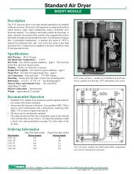
Description<br />
The 311C series <strong>air</strong> dryer is an insert module intended to be installed<br />
within an enclosure. The unit is a self-regenerative <strong>compressed</strong> <strong>air</strong> dryer<br />
which removes water vapor continuously using a molecular sieve<br />
desiccant material. Two stainless steel tanks contain the desiccant. A<br />
timer, solenoid valve and two flow control valves sequence the <strong>air</strong> flow<br />
alternately through one tank and then the other. A small amount of purge<br />
flow is discharged continuously. A nominal dew point of -50°F is<br />
achieved at maximum flow rate; even lower dew point at less than<br />
maximum flow. Compressed <strong>air</strong> supplied to the dryer should be clean<br />
(5 microns) and oil-free.<br />
Specifications<br />
Inlet Pressure – 80 to 125 psig<br />
Maximum Inlet Temperature – +125°F<br />
Dew Point – See chart for typical conditions – page 9. The lower the<br />
outlet flow, the lower the dew point.<br />
Medium – Oil-free <strong>air</strong>; filtered to 5 microns<br />
Output Flow Capacity – See chart for typical conditions – page 9<br />
Purge Flow – See chart for typical purge flow – page 9<br />
Air Connections – Inlet and outlet – 1/4" NPT Female<br />
Mounting – Mount unit with tanks vertical; four mounting holes<br />
Dimensions – 14-3/4" x 12-7/8" x 4" – See drawing page 9<br />
Electric Motor and Solenoid Valve – 120 volts/60 hz/<br />
single phase/15 watts<br />
Electric Connections – Terminal strip<br />
Weight – Approximately 21 pounds<br />
Recommended Operation<br />
• Install the 311C module in an enclosure to protect against inadvertent<br />
contact with electric terminals.<br />
• Always provide clean <strong>air</strong> to the dryer. Use a prefilter (OKC-730) to<br />
remove solid contamination and a downstream coalescing filter<br />
(OKC-731) to remove liquid water and oil.<br />
• The dryer can be continuously operated.<br />
• The output <strong>air</strong> pressure/flow has a momentary pulse as the solenoid<br />
valve switches flow (every 30 sec.). To reduce the pulsation, install<br />
a check valve and accumulator (see page 13) at the outlet of the<br />
<strong>air</strong> dryer.<br />
Ordering Information<br />
Max Flow Rate (scfm) Purge Flow Rate (scfm)<br />
Part Number 80 psig Supply 80 psig Supply<br />
311C-16 2.0 .35<br />
311C-22 3.4 .68<br />
311C-31 6.0 1.2<br />
311C-39 9.0 1.8<br />
311C-46 13.0 2.6<br />
Standard Air Dryer 7<br />
INSERT MODULE<br />
311C series <strong>air</strong> dryer – module for installation in enclosure.<br />
Unit is capable of achieving -50°F atmospheric dew point.<br />
Fixed Flow<br />
<strong>Controls</strong> (2)<br />
SS<br />
Desiccant<br />
Tanks (2)<br />
311C <strong>air</strong> dryer module has field replaceable components.<br />
Unit can be continuously operated.<br />
P.O. BOX Q • TRUMBULL, CT 06611 • CT PHONE (203) 261-6711 • TOLL FREE PHONE (800) 533-3285 • FAX (203) 261-8331<br />
© O'KEEFE CONTROLS CO. • 2001 ALL RIGHTS RESERVED e-mail ca@okcc.com • website www.okcc.com<br />
Timer<br />
4-way<br />
Solenoid<br />
Valve<br />
Muffler
8<br />
Standard Air Dryer<br />
FIELD MOUNT<br />
Description<br />
The 2016 series <strong>air</strong> dryer employs a solid state timer. Electric connections<br />
employ a DIN 43650 connector which is gasketed and protected against<br />
inadvertent contact. The unit is a self-regenerative <strong>compressed</strong> <strong>air</strong> dryer<br />
which removes water vapor continuously using a molecular sieve desiccant<br />
material. Two stainless steel tanks contain the desiccant. A timer, solenoid<br />
valve and two control valves sequence the <strong>air</strong> flow alternately through one<br />
tank and then the other. A small amount of purge flow is discharged<br />
continuously. A nominal dew point of -50°F is achieved at maximum flow<br />
rate; even lower dew point at less than maximum flow. Compressed <strong>air</strong><br />
supplied to the dryer should be clean (5 microns) and oil-free.<br />
Specifications<br />
Inlet Pressure – 80 to 125 psig<br />
Maximum Inlet Temperature – +125°F<br />
Dew Point – See chart for typical conditions – page 9. The lower the<br />
outlet flow, the lower the dew point.<br />
Medium – Oil-free <strong>air</strong>; filtered to 5 microns<br />
Output Flow Capacity – See chart for typical conditions – page 9<br />
Purge Flow – See chart for typical purge flow – page 9<br />
Air Connections – Inlet and outlet – 1/4" NPT Female<br />
Mounting – Mount unit with tanks vertical; four mounting holes<br />
Dimensions – 14-3/4" x 12-7/8" x 4" – See drawing page 9<br />
Electric Timer and Solenoid Valve – 120 volts/60 hz/<br />
single phase/15 watts<br />
Electric Connections – DIN 43650 (see optional cord below)<br />
Mating connector only – P/N OKC-2034<br />
Weight – Approximately 21 pounds<br />
Recommended Operation<br />
• The 2016 series <strong>air</strong> dryer has protected electrical connections and can<br />
be field mounted.<br />
• Always provide clean <strong>air</strong> to the dryer. Use a prefilter (OKC-730) to<br />
remove solid contamination and a coalescing filter (OKC-731) to<br />
remove liquid water and oil.<br />
• The dryer can be continuously operated.<br />
• The output <strong>air</strong> pressure/flow has a momentary pulse as the solenoid<br />
valve switches flow (every 30 sec.). To reduce the pulsation, install a<br />
check valve and accumulator (see page 13) at the outlet of the <strong>air</strong> dryer.<br />
Ordering Information<br />
Max Flow Rate (scfm) Purge Flow Rate (scfm)<br />
Part Number 80 psig Supply 80 psig Supply<br />
OKC-2016-16 2.0 .35<br />
OKC-2016-22 3.4 .68<br />
OKC-2016-31 6.0 1.2<br />
OKC-2016-39 9.0 1.8<br />
OKC-2016-46 13.0 2.6<br />
Optional Cord P/N OKC-822<br />
A six foot long cord with a 3-prong plug for 120 volts/<br />
60 hz has a DIN connector for attaching to the timer.<br />
Optional DIN Connector P/N OKC-2034<br />
Connector attaches to timer. Customer supplied 3-wire<br />
cord attaches to screw terminals in connector.<br />
Field mount <strong>air</strong> dryer has gasketed and protected electrical<br />
connections.<br />
All major components of the 2016 series <strong>air</strong> <strong>dryers</strong> are<br />
easily replaced.<br />
P.O. BOX Q • TRUMBULL, CT 06611 • CT PHONE (203) 261-6711 • TOLL FREE PHONE (800) 533-3285 • FAX (203) 261-8331<br />
© O'KEEFE CONTROLS CO. • 2001 ALL RIGHTS RESERVED e-mail ca@okcc.com • website www.okcc.com<br />
Fixed Flow Control Valves (2)<br />
DIN Connector<br />
Solid<br />
State<br />
Timer<br />
4-way<br />
Solenoid Valve<br />
Muffler<br />
SS Desiccant<br />
Tanks (2)
Insert Module<br />
1/4"<br />
14-3/4"<br />
14-1/4"<br />
12-7/8"<br />
12-1/4"<br />
(4) 9/32" Dia. Mounting Holes<br />
Standard Air Dryer 9<br />
SPECIFICATIONS<br />
Field Mount<br />
Operating Conditions for Standard Air Dryer<br />
Parts for Standard Air Dryers<br />
12-7/8"<br />
12-1/4"<br />
(4) 9/32" Dia. Mounting Holes<br />
Model 311C, 2016 -16 -22 -31 -39 -46<br />
Inlet pressure – PSIG 80 80 80 80 80<br />
Inlet temperature –°F 70 70 70 70 70<br />
Purge Flow – SCFM .35 .68 1.2 1.8 2.6<br />
Outlet Flow – SCFM 2.0 1.4 1.2 3.4 2.7 2.2 6.0 4.8 4.0 9.0 7.2 6.0 13.0 10.4 8.8<br />
Atmos. Dew Point –°F -50 -60 -65 -50 -60 -65 -50 -60 -65 -50 -60 -65 -50 -60 -65<br />
Dew Point @ 80 PSIG –°F -18 -30 -35 -18 -30 -35 -18 -30 -35 -18 -30 -35 -18 -30 -35<br />
Description Qty/Air Dryer Part Number<br />
Timer for 311C Series 1 OKC-781<br />
Timer for 2016 Series 1 OKC-2032<br />
Solenoid Valve for 311C Series 1 OKC-779<br />
Solenoid Valve for 2016 Series 1 OKC-2033<br />
Muffler for 311C, 2016 Series 1 OKC-780<br />
Desiccant Tank for 311C, 2016 Series<br />
Flow Control Valves for 311C, 2016 Series:<br />
2 OKC-777<br />
311C-16, OKC-2016-16 2 Y4F-16-BR-DE<br />
311C-22, OKC-2016-22 2 Y4F-22-BR-DE<br />
311C-31, OKC-2016-31 2 Y4F-31-BR-DE<br />
311C-39, OKC-2016-39 2 Y4F-39-BR-DE<br />
311C-46, OKC-2016-46 2 Y4F-46-BR-DE<br />
Din Connector for 2016 Series 1 OKC-2034<br />
P.O. BOX Q • TRUMBULL, CT 06611 • CT PHONE (203) 261-6711 • TOLL FREE PHONE (800) 533-3285 • FAX (203) 261-8331<br />
© O'KEEFE CONTROLS CO. • 2001 ALL RIGHTS RESERVED e-mail ca@okcc.com • website www.okcc.com<br />
5/16"<br />
1/4"<br />
14-3/4"<br />
14-1/4"<br />
5/16"
10<br />
Standard Air Dryer System<br />
ELECTRIC OPERATION<br />
Description<br />
Series 415 and 416 <strong>air</strong> dryer systems include the 311C series dryer, an<br />
enclosure and two filters completely assembled and ready for installation.<br />
The filters have automatic drains for discharge of collected liquids.<br />
Easily replaced filter cartridges remove solids to 5 microns in the first<br />
stage and liquids and solids to .03 microns in the second stage.<br />
Specifications<br />
Inlet Pressure – 80 to 125 psig<br />
Maximum Inlet Temperature – +125°F<br />
Dew Point – See chart for typical conditions – page 12. The lower the<br />
outlet flow, the lower the dew point.<br />
Medium – Compressed <strong>air</strong><br />
Output Flow Capacity – See chart for typical conditions – page 12<br />
Purge Flow – See chart for typical purge flow – page 12<br />
Air Connections – Inlet and outlet – 1/4" NPT Female<br />
Mounting – Mount unit with tanks vertical; four mounting holes<br />
Dimensions – 24" x 14" x 6" – See drawing page 12<br />
Electric Motor and Solenoid Valve – 120 volts/ 60 hz/<br />
single phase/15 watts<br />
Electric Connections – Terminal strip<br />
Filter Rating – Removes 99.99998% of all solid and liquid particles<br />
.03 microns and larger.<br />
Weight – Approximately 43 pounds<br />
Recommended Operation<br />
• The filters are equipped with automatic float drains. Make provision<br />
to collect the discharged liquid in a suitable location. There are 1/8"<br />
NPT connections in the bottom of each filter.<br />
• The dryer system works best if the <strong>compressed</strong> <strong>air</strong> provided is predried<br />
in a refrigeration type <strong>air</strong> dryer (35 to 50°F pressure dew point).<br />
• The dryer can be continuously operated.<br />
• The output <strong>air</strong> pressure/flow has a momentary pulse as the solenoid<br />
valve switches flow (every 30 sec.). To reduce the pulsation, install<br />
a check valve and accumulator (see page 13) at the outlet of the<br />
<strong>air</strong> dryer.<br />
Ordering Information<br />
Max Flow Rate (scfm) Purge Flow Rate (scfm)<br />
Part Number 80 psig Supply 80 psig Supply<br />
OKC-416B-1 2.0 .35<br />
OKC-416B-2 3.4 .68<br />
OKC-415B-1 6.0 1.2<br />
OKC-415B-2 9.0 1.8<br />
OKC-415B-3 13.0 2.6<br />
Air dryer systems consist of 311C insert module, enclosure<br />
and two filters.<br />
Flow<br />
Control<br />
Valve (2)<br />
SS<br />
Desiccant<br />
Tanks (2)<br />
Air In<br />
1/4" NPT<br />
Prefilter<br />
5 microns<br />
Coalescing<br />
Filter<br />
.03 micron<br />
Electric motor timer controls solenoid valve for automatic<br />
cycling of <strong>air</strong> dryer system.<br />
P.O. BOX Q • TRUMBULL, CT 06611 • CT PHONE (203) 261-6711 • TOLL FREE PHONE (800) 533-3285 • FAX (203) 261-8331<br />
© O'KEEFE CONTROLS CO. • 2001 ALL RIGHTS RESERVED e-mail ca@okcc.com • website www.okcc.com<br />
Solenoid<br />
Valve<br />
Timer<br />
Muffler<br />
Air Out 1/4" NPT
Standard Air Dryer System 11<br />
PNEUMATIC OPERATION<br />
Description<br />
Series 141/142 <strong>air</strong> dryer system has the unique feature of not requiring<br />
electric power for operation. Pneumatic timers and <strong>air</strong> operated relays<br />
are used for automatic control of the self-regenerative <strong>air</strong> dryer system.<br />
This pneumatic controlled <strong>air</strong> dryer can be installed in <strong>compressed</strong> <strong>air</strong><br />
lines to decrease the dew point to -50°F. A prefilter and coalescing filter<br />
both equipped with automatic drains are standard components of the<br />
system.<br />
Specifications<br />
Inlet Pressure – 80 to 125 psig<br />
Maximum Inlet Temperature – +125°F<br />
Dew Point – See chart for typical conditions – page 12. The lower the<br />
outlet flow, the lower the dew point.<br />
Medium – Compressed <strong>air</strong><br />
Output Flow Capacity – See chart for typical conditions – page 12<br />
Purge Flow – See chart for typical purge flow – page 12<br />
Air Connections – Inlet and outlet – 1/4" NPT Female<br />
Mounting – Mount unit with tanks vertical; four mounting holes<br />
Dimensions – 24" x 14" x 6" – See drawing page 12<br />
Control Pressure – Regulator preset to 50 psig. All connections<br />
internal.<br />
Filter Rating – Removes 99.99998% of all solid and liquid particles<br />
.03 microns and larger.<br />
Weight – Approximately 43 pounds<br />
Recommended Operation<br />
• The filters are equipped with automatic float drains. Make provision<br />
to collect the discharged liquid in a suitable location. There are<br />
1/8" NPT connections in the bottom of each filter.<br />
• The dryer system works best if the <strong>compressed</strong> <strong>air</strong> provided is predried<br />
in a refrigeration type <strong>air</strong> dryer (35 to 50°F pressure dew point).<br />
• The dryer can be continuously operated.<br />
• The output <strong>air</strong> pressure/flow has a momentary pulse as the solenoid<br />
valve switches flow (every 30 sec.). To reduce the pulsation, install<br />
a check valve and accumulator (see page 13) at the outlet of the<br />
<strong>air</strong> dryer.<br />
• The two timers are preset for periods of 30 seconds each. These<br />
should never be changed.<br />
Ordering Information<br />
Max Flow Rate (scfm) Purge Flow Rate (scfm)<br />
Part Number 80 psig Supply 80 psig Supply<br />
OKC-142C-1 2.0 .35<br />
OKC-142C-2 3.4 .68<br />
OKC-141C-1 6.0 1.2<br />
OKC-141C-2 9.0 1.8<br />
OKC-141C-3 13.0 2.6<br />
Air operated <strong>air</strong> dryer system does not require any<br />
electric power.<br />
Flow<br />
Control<br />
Valve (2)<br />
SS<br />
Desiccant<br />
Tanks (2)<br />
Muffler (2)<br />
Power<br />
Valve (2)<br />
Air In<br />
1/4" NPT<br />
Prefilter<br />
5 microns<br />
Coalescing<br />
Filter<br />
.03 micron<br />
Air timers and <strong>air</strong> relays automatically cycle the selfregenerating<br />
<strong>air</strong> dryer.<br />
P.O. BOX Q • TRUMBULL, CT 06611 • CT PHONE (203) 261-6711 • TOLL FREE PHONE (800) 533-3285 • FAX (203) 261-8331<br />
© O'KEEFE CONTROLS CO. • 2001 ALL RIGHTS RESERVED e-mail ca@okcc.com • website www.okcc.com<br />
Air<br />
Timers<br />
Relay<br />
Valves<br />
Timer<br />
Regulator<br />
Air Out 1/4" NPT
12<br />
Standard Air Dryer System<br />
DIMENSIONS<br />
For Both Pneumatic and Electric Operation<br />
*Series<br />
1/4"<br />
NPT<br />
Inlet<br />
B<br />
A<br />
C<br />
14-1/4"<br />
12"<br />
1/4" NPT<br />
Outlet<br />
Oil/Water<br />
Removing Filter<br />
Prefilter<br />
(4) 5/16" Dia. Mtg. Holes<br />
6-1/4"<br />
Parts for Standard Air Dryer Systems<br />
16-1/4"<br />
16-3/4"<br />
Dimensions – In.<br />
Operating Conditions for Standard Air Dryer Systems<br />
Series A B C<br />
OKC-141C 6.37" .98" 3.35"<br />
OKC-142C 5.60" .90" 3.00"<br />
OKC-415B 6.37" .98" 3.35"<br />
OKC-416B 5.60" .90" 3.00"<br />
Series *-16 *-22 *-31 *-39 *-46<br />
Inlet pressure – PSIG 80 80 80 80 80<br />
Inlet temperature –°F 70 70 70 70 70<br />
Purge Flow – SCFM .35 .68 1.2 1.8 2.6<br />
Outlet Flow – SCFM 2.0 1.4 1.2 3.4 2.7 2.2 6.0 4.8 4.0 9.0 7.2 6.0 13.0 10.4 8.8<br />
Atmos. Dew Point –°F -50 -60 -65 -50 -60 -65 -50 -60 -65 -50 -60 -65 -50 -60 -65<br />
Dew Point @ 80 PSIG –°F -18 -30 -35 -18 -30 -35 -18 -30 -35 -18 -30 -35 -18 -30 -35<br />
Description Qty./Air Dryer Part Number<br />
Muffler for 141C/142C 2 APC-246-2<br />
Muffler for 415B/416B 1 OKC-780<br />
Desiccant Tank for 141C/142C/415B/416B 2 OKC-777<br />
Prefilter Assembly for 142C/416B 1 OKC-740<br />
Prefilter Assembly for 141C/415B 1 OKC-730<br />
Prefilter Replacement Cartridge for 142C/416B 1 OKC-742<br />
Prefilter Replacement Cartridge for 141C/415B 1 OKC-732<br />
Coalescing Filter Assembly for 142C/416B 1 OKC-740<br />
Coalescing Filter Assembly for 141C/415B 1 OKC-731<br />
Coalescing Filter Cartridge for 142C/416B 1 OKC-742<br />
Coalescing Filter Cartridge for 141C/415B 1 OKC-733<br />
Flow Control Valve<br />
For 416B-1; 142C-1 2 Y4F-16-BR-DE<br />
For 416B-2; 142C-2 2 Y4F-22-BR-DE<br />
For 415B-1; 141C-1 2 Y4F-31-BR-DE<br />
For 415B-2; 141C-2 2 Y4F-39-BR-DE<br />
For 415B-3; 141C-3 2 Y4F-46-BR-DE<br />
Timer for 415B/416B 1 OKC-781<br />
Timer for 141C/142C 2 OKC-893<br />
Solenoid Valve for 415B/416B 1 OKC-779<br />
Power Valve for 141C/142C 2 OKC-892<br />
Relay Valve for 141C/142C (Detent) 1 OKC-894<br />
Relay Valve for 141C/142C (Spring Return) 1 OKC-1220<br />
Pressure Regulator for 141C/142C 1 OKC-1222<br />
Pressure Gage for 141C/142C 1 OKC-1221<br />
P.O. BOX Q • TRUMBULL, CT 06611 • CT PHONE (203) 261-6711 • TOLL FREE PHONE (800) 533-3285 • FAX (203) 261-8331<br />
© O'KEEFE CONTROLS CO. • 2001 ALL RIGHTS RESERVED e-mail ca@okcc.com • website www.okcc.com
Compressed Air Accumulators 13<br />
AIR RESERVOIRS<br />
Description<br />
Compressed <strong>air</strong> accumulators serve to reduce or eliminate pulsation<br />
which occurs twice in each cycle of twin tower, self-regenerative<br />
<strong>compressed</strong> <strong>air</strong> <strong>dryers</strong>. The accumulators are complete with an inlet<br />
check valve, a 125 psig relief valve, and an output pressure regulator.<br />
The portable 20 gallon unit can also be used as a storage tank for clean,<br />
dry <strong>compressed</strong> <strong>air</strong>. Useable for low flow requirements at a remote<br />
lcoation that does not have a <strong>compressed</strong> <strong>air</strong> source.<br />
Applications<br />
• Pulse reduction in cyclic <strong>air</strong> dryer system.<br />
• Pressure regulation in precision pneumatic systems.<br />
• Portable <strong>air</strong> source for temporary low flow requirements.<br />
Specifications<br />
Storage Volume – Series 2055 – 3 gallon<br />
– Series 2054 – 20 gallon<br />
Maximum Pressure – 125 psig<br />
Relief Valve Setting – 125 psig<br />
Tank Material – Steel<br />
Dimensions – See drawing.<br />
Output Pressure Regulator – Adjustable – see range in chart below.<br />
ASME Code – Series 2054 only.<br />
Connections – 1/4" NPT<br />
Ordering Information Output Gage<br />
Pressure Regulator Range<br />
3 Gallon 20 Gallon (psig) Type (psig)<br />
OKC-2055-1 OKC-2054-1 0-125 General Purpose 0-160<br />
OKC-2055-2 OKC-2054-2 0-125 Precision 0-160<br />
OKC-2055-4 OKC-2054-4 0-60 Precision 0-60<br />
OKC-2055-5 OKC-2054-5 0-30 Precision 0-30<br />
OKC-2055-6 OKC-2054-6 0-20 Precision 0-20<br />
OKC-2055-7 OKC-2054-7 0-10 Precision 0-15<br />
OKC-2055-8 OKC-2054-8 0-2 Precision 0-3<br />
Custom Assemblies<br />
A variety of tank sizes and styles are available for pressures up to<br />
125 psig. The tanks can be equipped with check valves, relief valves,<br />
filters, pressure regulators or gages as required. Consult factory with<br />
your requirements.<br />
13 3/8"<br />
Air<br />
In<br />
Check Valve<br />
Relief Valve<br />
3 Gallon Tank<br />
Air<br />
Our<br />
(4) 1/2" Dia. Mtg. Holes<br />
25 1/4"<br />
Drain<br />
Valve<br />
Regulator<br />
3 gallon accumulator includes check valve, relief valve and<br />
output pressure regulator with gage.<br />
Accumulator reduces pressure surges caused by cycling <strong>air</strong><br />
dryer system, or sudden output flow changes.<br />
Relief Valve<br />
20 Gallon Tank<br />
Drain Valve<br />
31 1/2"<br />
40 1/2"<br />
Regulator<br />
Air<br />
Out 22 7/8"<br />
Air In<br />
Check<br />
Valve<br />
20 gallon accumulator is portable. Semi-pneumatic tires and<br />
handle are standard.<br />
Portable 20 gallon tank can provide clean, dry <strong>compressed</strong><br />
<strong>air</strong> to a remote location.<br />
P.O. BOX Q • TRUMBULL, CT 06611 • CT PHONE (203) 261-6711 • TOLL FREE PHONE (800) 533-3285 • FAX (203) 261-8331<br />
© O'KEEFE CONTROLS CO. • 2001 ALL RIGHTS RESERVED e-mail ca@okcc.com • website www.okcc.com
14<br />
High Flow Air Dryer Module<br />
20 SCFM • QUIET OPERATION<br />
Description<br />
The series 2042 high flow <strong>air</strong> dryer will handle up to 20 scfm at supply<br />
pressure of 80 to 125 psig. Using a solid state timer, three power valves<br />
are sequenced to provide the following features:<br />
• Quiet operation – No large pressure surge during switching.<br />
• Virtual pulse free output pressure – No significant pressure swing<br />
during switching.<br />
• Three models rated at 10, 15 and 20 scfm respectively.<br />
Construction is simplified and cost is reduced using an open frame<br />
assembly for this series. All electric components are housed in a small<br />
Nema 12/13 enclosure. Valves and desiccant tanks are plate mounted.<br />
Specifications<br />
Inlet Pressure – 80 to 125 psig<br />
Maximum Inlet Temperature – +125°F<br />
Dew Point – minus 50°F atmospheric at maximum rated flow;<br />
dew point decreases at flow rates less than maximum.<br />
Medium – Clean oil-free <strong>compressed</strong> <strong>air</strong>.<br />
Output Flow Capacity – 10, 15 or 20 scfm – See chart below.<br />
Purge Flow – See chart below.<br />
Air Connections – 1/2" NPT or 1/2" OD plastic tubing.<br />
Mounting – Mount unit vertical and upright; six mounting holes.<br />
Dimensions – 33" x 21" x 7" – See drawing page 16.<br />
Electric Connections – Terminal strip inside enclosure.<br />
Required Filtration – Prefilter – 5 micron<br />
Coalescing filter – .01 micron<br />
Weight – Approximately 60#.<br />
Recommended Operation<br />
• The 2042 series <strong>air</strong> dryer has protected electrical connections and<br />
can be field mounted.<br />
• Always provide clean <strong>air</strong> to the dryer. Use a prefilter (OKC-2046) to<br />
remove solid contamination and a coalescing filter (OKC-2047) to<br />
remove liquid water and oil.<br />
• The dryer can be continuously operated.<br />
Ordering Information<br />
Max Flow Purge Flow<br />
Rate Rate Atmos. Pressure<br />
(scfm) (scfm) Dew Point Dew Point<br />
Part Number @ 80 psig @ 80 psig °F . °F .<br />
OKC-2042-1 10 2 -50 -18<br />
OKC-2042-2 15 3 -50 -18<br />
OKC-2042-3 20 4 -50 -18<br />
Open frame <strong>air</strong> dryer module can handle up to 20 scfm at<br />
80 psig and deliver an output dew point of -50°F atmospheric.<br />
Flow Control Valves (2)<br />
Air dryer employs a solid state timer, three power valves and<br />
two tanks of desiccant to achieve low dew point.<br />
P.O. BOX Q • TRUMBULL, CT 06611 • CT PHONE (203) 261-6711 • TOLL FREE PHONE (800) 533-3285 • FAX (203) 261-8331<br />
© O'KEEFE CONTROLS CO. • 2001 ALL RIGHTS RESERVED e-mail ca@okcc.com • website www.okcc.com<br />
Desiccant Tank<br />
Power<br />
Valve (3)<br />
Desiccant Tank<br />
Timer<br />
and<br />
Solenoid<br />
Valves<br />
Inside<br />
Connect<br />
Electric<br />
Power<br />
120/60<br />
Muffler
High Flow Air Dryer System 15<br />
PULSE FREE<br />
Description<br />
The series 2043 high flow <strong>air</strong> dryer system handles up to 20 scfm at<br />
supply pressure of 80 to 125 psig. Using a solid state timer, three power<br />
valves are sequenced to provide the following features:<br />
• Quiet operation – No large pressure surge during switching.<br />
• Virtual pulse free output pressure – No significant pressure swing<br />
during switching.<br />
• Three models rated at 10, 15 and 20 scfm respectively.<br />
The <strong>air</strong> dryer is housed in a Nema 12/13 enclosure and a prefilter and<br />
coalescing filter are attached externally. The system can handle substantial<br />
<strong>air</strong> flows without attracting attention or creating noise disturbances.<br />
Specifications<br />
Inlet Pressure – 80 to 125 psig<br />
Maximum Inlet Temperature – +125°F<br />
Dew Point – minus 50°F atmospheric at maximum rated flow;<br />
dew point decreases at flow rates less than maximum.<br />
Medium – Clean <strong>compressed</strong> <strong>air</strong>.<br />
Output Flow Capacity – 10, 15 or 20 scfm – See chart below.<br />
Purge Flow – See chart below.<br />
Air Connections – 1/2" NPT<br />
Mounting – Mount unit vertical and upright; four mounting holes.<br />
Dimensions – 36" x 24" x 7" – enclosure only – See drawing page 16.<br />
Electric Connections – Terminal strip on timer sub-plate.<br />
Filtration – Prefilter with auto drain – 5 micron<br />
Coalescing filter with auto drain – .01 micron<br />
Weight – Approximately 120#.<br />
Recommended Operation<br />
• The filters are equipped with automatic float drains. Make provision<br />
to collect the discharged liquid at a suitable location. There are<br />
1/8" NPT connections at the bottom of each filter.<br />
• The dryer system works best if the <strong>compressed</strong> <strong>air</strong> provided is predried<br />
in a refrigeration type <strong>air</strong> dryer (35 to 50°F pressure dew point).<br />
• The dryer can be continuously operated.<br />
Ordering Information<br />
Max Flow Purge Flow<br />
Rate Rate Atmos. Pressure<br />
(scfm) (scfm) Dew Point Dew Point<br />
Part Number @ 80 psig @ 80 psig °F . °F .<br />
OKC-2043-1 10 2 -50 -18<br />
OKC-2043-2 15 3 -50 -18<br />
OKC-2043-3 20 4 -50 -18<br />
External filters remove solids and liquids from <strong>compressed</strong><br />
<strong>air</strong>. The dryer removes water vapor from the <strong>air</strong>.<br />
Flow Control Valves (2)<br />
A solid state timer sequences the three power valves to assure<br />
quiet, pulse-free operation.<br />
P.O. BOX Q • TRUMBULL, CT 06611 • CT PHONE (203) 261-6711 • TOLL FREE PHONE (800) 533-3285 • FAX (203) 261-8331<br />
© O'KEEFE CONTROLS CO. • 2001 ALL RIGHTS RESERVED e-mail ca@okcc.com • website www.okcc.com<br />
Air<br />
In<br />
Prefilter<br />
Coalescing<br />
Filter<br />
Desiccant Tank<br />
Desiccant Tank<br />
Power<br />
Valve<br />
(3)<br />
Muffler<br />
Air<br />
Out<br />
Solid<br />
State<br />
Timer<br />
Pilot<br />
Valves<br />
(3)
16<br />
Module<br />
Series 2042<br />
21.00<br />
Dim. – In.<br />
High Flow Air Dryers<br />
16.50<br />
.88<br />
Typ.<br />
33.00<br />
.88 Typ.<br />
(6) .50 Dia. Mtg. Holes<br />
Parts for High Flow Air Dryers<br />
DIMENSIONS<br />
Dim. – In.<br />
P.O. BOX Q • TRUMBULL, CT 06611 • CT PHONE (203) 261-6711 • TOLL FREE PHONE (800) 533-3285 • FAX (203) 261-8331<br />
© O'KEEFE CONTROLS CO. • 2001 ALL RIGHTS RESERVED e-mail ca@okcc.com • website www.okcc.com<br />
11.00<br />
1/2" NPT – Air In<br />
9.19<br />
3.00<br />
System<br />
Series 2043<br />
.44 Dia. – Mtg. Holes<br />
24.00<br />
Description Qty./Air Dryer Part Number<br />
Timer for 2042; 2043 (120/60) 1 OKC-1150-2<br />
Solenoid Valve for 2042; 2043 (120/60) 3 OKC-2050-2<br />
Check Valve for 2042; 2043 1 FFLC-2-BR<br />
Flow Control Valve<br />
For 2042-1; 2043-1 2 Y6F-41-BR-DE<br />
For 2042-2; 2043-2 2 Y6F-52-BR-DE<br />
For 2042-3; 2043-3 2 Y6F-60-BR-DE<br />
Muffler for 2042; 2043 1 OKC-2051<br />
Desiccant Tank for 2042; 2043 2 OKC-2052<br />
Power Valve for 2042; 2043 3 OKC-2049<br />
Prefilter for 2043 1 OKC-2046<br />
Prefilter Cartridge for 2043 1 OKC-732<br />
Coalescing Filter for 2043 1 OKC-2047<br />
Coalescing Filter Cartridge for 2043 1 OKC-733<br />
Autodrain Assembly for 2043 2 OKC-734<br />
.44<br />
18.00<br />
8.50<br />
7.00<br />
4.25<br />
1/2" NPT<br />
Air Out<br />
36.00<br />
37.20
Description<br />
The "point-of-use" <strong>compressed</strong> <strong>air</strong> dryer removes<br />
liquid water using filters; and reduces<br />
the pressure dew point of the <strong>air</strong> through<br />
pressure reduction. The system consists of a<br />
prefilter and a coalescing filter, followed by<br />
a pressure regulator. Two gages and mounting<br />
hardware are included in the system.<br />
Maximum flow rates of 10, 20 and 40 scfm<br />
are available as standard.<br />
While depression of dew point with the<br />
system is not as dramatic as in desiccant <strong>air</strong><br />
<strong>dryers</strong>, it is an economical approach to solving<br />
local in-plant <strong>air</strong> line water problems.<br />
How It Works!<br />
Assume that the <strong>air</strong> entering the filters contains<br />
liquid water and water vapor at 100%<br />
relative humidity. The <strong>air</strong> exiting the filters<br />
is virtually free of liquid water, but is still at<br />
100% relative humidity as it enters the pressure<br />
regulator.<br />
Since pressure regulators reduce pressure,<br />
there is a corresponding decrease in the<br />
density of the <strong>air</strong> at the exit from the regulator.<br />
Not only is the density of the <strong>air</strong> reduced,<br />
but also that of the water vapor, resulting in<br />
a decrease of the relative humidity. Saturated<br />
water vapor entering the regulator is no<br />
longer saturated in the reduced pressure at<br />
the outlet.<br />
The dew point chart (at right) illustrates the<br />
reduction of dew point that can be achieved.<br />
The lower the outlet pressure of the regulator<br />
the lower is the relative humidity and associated<br />
dew point. The assumption for the chart<br />
data is that heat transfer maintains the temperature<br />
reasonably constant during flow<br />
passage through the pressure regulator.<br />
Where To Use the Air Dryer!<br />
Install this dryer close to the "point of use" to<br />
insure that there is no substantial temperature<br />
decrease between the regulator and<br />
downstream use point.<br />
It is good practice to maintain the regulator<br />
output pressure a minimum of 20 psi below<br />
the regulator input pressure. The two gages<br />
provided are for this purpose.<br />
Point-of-Use Air Dryer System 17<br />
DEW POINT REDUCTION<br />
Point-of-use <strong>air</strong> dryer contains two filters,<br />
two pressure gages and one regulator.<br />
Ordering Information<br />
Part Maximum Connections<br />
Number Flow – SCFM NPT<br />
OKC-2039-1 10 scfm 1/4"<br />
OKC-2039-2 20 scfm 3/8"<br />
OKC-2039-3 40 scfm 1/2"<br />
Dimensions<br />
C<br />
Prefilter<br />
Inlet<br />
NPT<br />
1/8" NPT -<br />
Male (2)<br />
(2) Mounting<br />
Brackets<br />
Filters remove condensate before <strong>air</strong><br />
enters regulator. Regulator reduces<br />
outlet pressure and the dew point drops<br />
accordingly.<br />
P.O. BOX Q • TRUMBULL, CT 06611 • CT PHONE (203) 261-6711 • TOLL FREE PHONE (800) 533-3285 • FAX (203) 261-8331<br />
© O'KEEFE CONTROLS CO. • 2001 ALL RIGHTS RESERVED e-mail ca@okcc.com • website www.okcc.com<br />
A<br />
B<br />
Inlet<br />
Pressure<br />
Gage<br />
Coalescing Filter<br />
Outlet<br />
Pressure<br />
Gage<br />
Pressure<br />
Regulator<br />
D<br />
Outlet<br />
NPT<br />
Specifications<br />
Media – Compressed <strong>air</strong><br />
Connections –<br />
Process – 1/4", 3/8" or 1/2" NPT<br />
Drains – 1/8" NPT male<br />
Inlet Pressure Range – 80-150 psig<br />
Inlet Temperature Range – +40 to 125°F<br />
Maximum Flow Rate – up to 40 scfm<br />
Consult factory for larger flow rates.<br />
Outlet Pressure Range – 1-150 psig<br />
Filtration – .01 micron through dual filters.<br />
Liquid Drains – Automatic float in<br />
each filter. 1/8" NPT connection.<br />
Mounting – Integral brackets;<br />
See dimension drawing.<br />
Dimensions – See drawing and chart.<br />
Filter Elements – Replaceable<br />
Materials of Construction –<br />
Filter Bowl – Polycarbonate<br />
Filter Body – Zinc<br />
Regulator Body – Zinc<br />
Bowl Guard – Aluminum<br />
Dew Point Chart<br />
Point-of-Use Air Dryer<br />
Regulator Inlet Air Conditions<br />
• 100 psig, 70°F, 100% RH<br />
• Contains no condensate<br />
• Barometric pressure 14.7 psia<br />
Output Relative Pressure<br />
Pressure Humidity Dew Point<br />
psig % °F<br />
100 100 70.0<br />
90 91.0 67.3<br />
80 82.6 64.5<br />
70 73.8 61.2<br />
60 65.1 57.7<br />
50 56.4 53.9<br />
40 47.7 49.5<br />
30 39.0 44.0<br />
20 30.3 37.5<br />
10 21.5 29.0<br />
0 12.8 16.5<br />
Type A B C D NPT<br />
OKC-2039-1 10-5/8" 4-5/8" 3" 7-1/2" 1/4"<br />
OKC-2039-2 11-3/4" 4-15/16" 3" 8-1/4" 3/8"<br />
OKC-2039-3 11-3/4" 4-15/16" 3" 8-1/4" 1/2"
18<br />
Air Dryer Accessories<br />
IN-LINE FLOWMETERS WITH PRESSURE GAGE – AIR SERVICE<br />
Calibrated for Inlet Pressures 40-100 psig • Vertical or Horizontal ➝ Mounting<br />
Pipe Size Flow Range Approximate Inlet Maximum<br />
Part No.* Female NPT SCFM to Outlet Dim. Height<br />
OKC-1000-1 1/4" 1-4 6-3/4" 4-1/4"<br />
OKC-1000-2 1/4" 2-9 6-3/4" 4-1/4"<br />
OKC-1000-3 1/4" 2-18 6-3/4" 4-1/4"<br />
OKC-1000-5 1/2" 2-20 9-1/4" 4-3/4"<br />
OKC-1000-6 1/2" 10-60 9-1/4" 4-3/4"<br />
OKC-1000-10 3/4" 5-50 10-1/2" 5-1/4"<br />
OKC-1000-11 3/4" 10-90 10-1/2" 5-1/4"<br />
*Maximum Pressure 150 psig; Maximum Temperature 150°F<br />
FLOW METERS – AIR SERVICE – ROTAMETER STYLE<br />
Calibrated for Standard Atmospheric Conditions • Vertical Mounting Only<br />
Air Flow Range Dimensions Maximum<br />
Part No.* (SCFH) Overall Height Scale Length Connection Pressure<br />
KRMA-1 .05 - .5 4-9/16" 2" 1/8" NPT 100 psig<br />
KRMA-3 .2 - 2 4-9/16" 2" 1/8" NPT 100 psig<br />
KRMA-5 1-10 4-9/16" 2" 1/8" NPT 100 psig<br />
KRMB-52 5-50 8-1/2" 5" 1/4" NPT 70 psig<br />
KRMB-54 20-200 8-1/2" 5" 1/4" NPT 70 psig<br />
KRMC-104 40-400 15-1/8" 10" 1/2" NPT 35 psig<br />
KRMC-106 100-1000 15-1/8" 10" 1/2" NPT 35 psig<br />
KRMC-108 180-1800 15-1/8" 10" 1/2" NPT 35 psig<br />
*Maximum Temperature 130°F<br />
Part No. Output Supply<br />
Part No.* With Gage Size Pressure (max.) Dimensions<br />
OKC-1045-1 OKC-1045-1G 0-2 psig<br />
OKC-1045-2 OKC-1045-2G 0-10 psig Inlet to<br />
OKC-1045-3<br />
OKC-1045-4<br />
OKC-1045-3G<br />
OKC-1045-4G<br />
1/4"<br />
NPT<br />
0-20 psig<br />
0-30 psig<br />
400 psig<br />
Outlet
13.00"<br />
4.62"<br />
Air Dryer Accessories 19<br />
MOISTURE INDICATORS<br />
These moisture indicators contain silica gel. Moist <strong>air</strong> with a dew point greater than 4°F will cause the color to change from blue to pink<br />
(or clear). When dry <strong>air</strong> (less than 4°F) flows through the indicator the blue color is restored.<br />
Trace Flow<br />
1-1/2"<br />
Dia.<br />
Part No. OKC-1739<br />
3"Dia. Out Part No. OKC-1015 1-1/2" Part No. OKC-2038<br />
Connections –<br />
Inlet – 1/2" - 20 (O-Ring Seal)<br />
Connections – 1/2" NPT Female Air<br />
In<br />
Flow – In Line (no trace flow)<br />
Trace Connection – 1/4" NPT<br />
Flow<br />
Trace Air Flow – 2 scfh<br />
2-1/2" Outlet – Flow to Atmos.<br />
Trace Air Flow – 2 scfh @ 100 psig<br />
7-3/8"<br />
Max. Flow – 15 scfm<br />
Mounting – Vertical/Upright<br />
3-1/2" Mounting – Vertical/Upright<br />
Media – Oil-free <strong>air</strong><br />
Mounting – Vertical/Upright Media – Oil-free <strong>air</strong> Max. Pressure – 125 psig<br />
11/16"<br />
Hex Media – Oil-free <strong>air</strong> Max. Pressure – 100 psig<br />
Thread 1/2-20<br />
(O-Ring Seal) Max. Pressure – 125 psig<br />
Air<br />
In<br />
1/2" NPT<br />
LINE TEE IN-LINE REMOTE<br />
H<br />
W<br />
1/2" NPT<br />
Air<br />
CHEMICAL DRYERS<br />
Part No. OKC-2037-1 Part No. OKC-2037-2<br />
This dryer will remove moisture from This dryer will remove moisture from<br />
<strong>compressed</strong> <strong>air</strong> up to a total of 4400 <strong>compressed</strong> <strong>air</strong> up to a total of 600<br />
standard cubic feet per the following standard cubic feet per the following<br />
specifications. specifications.<br />
Inlet Pressure – 100 psig Inlet Pressure – 100 psig<br />
Maximum Flow – 10 scfm Maximum Flow – 5 scfm<br />
Atmos. Dew Point – minus 45°F Atmos. Dew Point – minus 45°F<br />
Desiccant – Silica Gel Desiccant – Silica Gel<br />
Connections are 1/4" NPT Female Connections are 1/4" NPT Female<br />
The desiccant when saturated must be replaced. Silica gel changes color from<br />
blue to pink as the material becomes saturated.<br />
The application for this dryer is for low flow requirements or for higher<br />
flow situations which operate only occasionally.<br />
FINE AIR FILTERS<br />
Connection Micron Dimensions Max. Flow Max.<br />
Part No.** Size Rating Drain W H SCFM Pressure*<br />
OKC-1379 1/4" NPT 5 Manual 1.5" 3.6" 3 150 psig<br />
OKC-1380 1/4" NPT .01 Manual 1.5" 3.6" 3 150 psig<br />
OKC-739 1/4" NPT 5 Auto 3.0" 7.5" 10 150 psig<br />
OKC-740 1/4" NPT .01 Auto 3.0" 7.5" 10 150 psig<br />
OKC-730 1/4" NPT 5 Auto 3.3" 8.2" 20 150 psig<br />
OKC-731 1/4" NPT .01 Auto 3.3" 8.2" 20 150 psig<br />
*Maximum Operating Temperature 125°F<br />
**Filter bowls are polycarbonate. Metal bowl guard included.<br />
PRESSURE GAGES<br />
BOTTOM MOUNT BACK MOUNT<br />
Part Pressure Part Pressure<br />
Number Range (psig) Number Range (psig)<br />
OKC-2035-1 0-5 OKC-2036-2 0-15<br />
OKC-2035-2 0-15 OKC-2036-3 0-30<br />
OKC-2035-3 0-30 OKC-2036-4 0-60<br />
OKC-2035-4 0-60 OKC-2036-5 0-100<br />
OKC-2035-5 0-100 OKC-2036-6 0-160<br />
OKC-2035-6 0-160<br />
Bottom mount pressure gages have Back mount pressure gages have<br />
2-1/2" dial; 1/4" NPT brass connection. 2" dial; 1/4" NPT brass connection.<br />
P.O. BOX Q • TRUMBULL, CT 06611 • CT PHONE (203) 261-6711 • TOLL FREE PHONE (800) 533-3285 • FAX (203) 261-8331<br />
© O'KEEFE CONTROLS CO. • 2001 ALL RIGHTS RESERVED e-mail ca@okcc.com • website www.okcc.com<br />
PIPE<br />
5.53"<br />
2.73"
20<br />
Automatic Drain Valves<br />
TIMED RELEASE<br />
Description<br />
The Automatic Timed Solenoid Valve is a combination of a brass body<br />
directional control valve and an attached electronic repeat cycle timer<br />
which alternately opens and closes the valve. The valves are industrial<br />
quality, suitable for <strong>air</strong> or water service. The timer has an off time period<br />
(valve de-energized) that is adjustable from 1 - 45 minutes. The on time<br />
period (valve energized) is adjustable from 1 - 15 seconds. A touch<br />
button manual override on the electronic timer allows for manual<br />
control of the valve.<br />
Applications<br />
The Automatic Timed Solenoid Valve can be used to discharge water<br />
collected in tanks, pipes, filters or refrigeration <strong>dryers</strong> in <strong>compressed</strong> <strong>air</strong><br />
systems. The valve opens periodically for a short duration and discharges<br />
collected water into a drain or sump.<br />
The valve can also be used to periodically spray water for cooling or<br />
wetting of produce, vegetation, or equipment.<br />
General Specifications<br />
Electronic Timer<br />
Voltage – 120 volts<br />
Frequency – 60 hz<br />
Energize Time – 1-15 seconds<br />
De-energize Time – 1-45 minutes<br />
Manual Override – Touch button<br />
Power On Light – LED • Red<br />
Valve Energized Light – LED • Green<br />
Ambient Temperature – +32° to 125°F<br />
Power Output to Valve – 20 watts max<br />
Connections – DIN Size 30/40<br />
Enclosure Protection – Equivalent to Types 1 and 4<br />
Housing Material – Polycarbonate<br />
Solenoid Valves<br />
Materials – Brass Body • BUNA N Seals<br />
Compatible Fluids – Air, Water<br />
Pressure & Flow (Cv) – See chart on page 21<br />
Power – Less than 20 watts<br />
Voltage/Frequency* – 120/60<br />
Enclosure – Types 1, 2, 3, and 4<br />
Ambient Temperature – +32° to 125°F<br />
Connections – Female Pipe Threads<br />
Valve<br />
Energized<br />
Timed Solenoid Valve<br />
Electronic Timer<br />
Manual<br />
Override<br />
Touch Button<br />
Green Light<br />
On When<br />
Valve Is<br />
Energized<br />
Adjustment<br />
For Duration<br />
That Valve<br />
Is Energized<br />
Timing Diagram<br />
Valve<br />
De-energized<br />
Energize Time<br />
{1 - 15 Seconds<br />
Dwell<br />
Time<br />
1 - 45 Minutes<br />
P.O. BOX Q • TRUMBULL, CT 06611 • CT PHONE (203) 261-6711 • TOLL FREE PHONE (800) 533-3285 • FAX (203) 261-8331<br />
© O'KEEFE CONTROLS CO. • 2001 ALL RIGHTS RESERVED e-mail ca@okcc.com • website www.okcc.com<br />
VIEW A<br />
ROTATED 180°<br />
Power On<br />
Light (Red)<br />
Adjustment For<br />
Dwell Time.<br />
Valve Is<br />
De-energized<br />
During Dwell<br />
Time.
Dimensions<br />
Valve Selection<br />
Select a valve for the application compatible with the pressure<br />
and flow requirements. For draining gravity pressurized vessels<br />
select a valve with a minimum pressure differential rating of<br />
"0" psig. Such a valve will operate even at low liquid levels in<br />
the vessel.<br />
Optional Power Cord (120 volts/60 hz)<br />
A six foot long power cord with a 3-prong plug for 120 volts/60 hz<br />
has a DIN connector for attaching to the timer. Part No. OKC-822.<br />
Options Available<br />
Consult the factory for any of the following options.<br />
Voltage – 24/60 or 240/60<br />
Materials – Stainless Steel Body or Alternate Valve Seals<br />
Slow Closing Construction – to avoid water hammer<br />
Other Fluids – steam, deionized water, or chemicals<br />
Automatic Drain Valves 21<br />
ADJUSTABLE TIMING<br />
Dimension Chart<br />
Part Number<br />
Pipe<br />
Size<br />
(In.)<br />
Type H L L1 P W W1<br />
OKC-821/1G212 1/4 N.C. 3-29/32 1-9/16 3-13/32 3-9/32 — 1-31/32<br />
OKC-821/1G262 1/4 N.O. 3-3/4 1-1/4 DIA. 3-1/2 3-11/32 — 1-31/32<br />
OKC-821/100G1 3/8 N.C. 3-3/4 2-3/4 2-5/8 3-3/16 2-5/16 —<br />
OKC-821/10G93 3/8 N.C. 4-3/8 2-3/4 2-13/16 3-13/16 2-5/16 —<br />
OKC-821/10G33 3/8 N.O. 4-13/16 2-3/4 2-13/16 4-1/4 2-9/32 —<br />
OKC-821/100G2 1/2 N.C. 3-3/4 2-3/4 2-5/8 3-3/16 2-5/16 —<br />
OKC-821/10G94 1/2 N.C. 4-3/8 2-3/4 2-13/16 3-13/16 2-5/16 —<br />
OKC-821/10G34 1/2 N.O. 4-13/16 2-3/4 2-13/16 4-1/4 2-9/32 —<br />
OKC-821/100G3 3/4 N.C. 4-1/2 3-25/32 2-1/8 3-7/8 2-3/4 —<br />
OKC-821/10G95 3/4 N.C. 4-19/32 2-13/16 2-25/32 3-29/32 2-5/16 —<br />
OKC-821/10G35 3/4 N.O. 5-3/32 2-13/16 2-25/32 4-15/32 2-9/32 —<br />
OKC-821/100G4 1 N.C. 5-31/32 3-3/4 2-1/8 4-11/32 2-15/16 —<br />
OKC-821/100G8 1-1/4 N.C. 5-31/32 3-21/32 2-5/32 4-11/32 3-3/8 —<br />
OKC-821/10G22 1-1/2 N.C. 6-15/32 4-3/8 1-13/16 4-1/2 3-3/4 —<br />
OKC-821/1G100 2 N.C. 7-21/32 5-1/16 1-15/32 4-29/32 4-11/16 —<br />
Dimensions – In.<br />
Valve Specifications<br />
Brass Body • Buna-N Seals<br />
Pipe Differential Part Number* Size Type<br />
Fluid Cv Coil<br />
Pressure PSIG (In.) Min. Max.<br />
Temp.<br />
Max – °F<br />
Flow<br />
Factor<br />
Watt<br />
Rating<br />
OKC-821/1G212 1/4 N.C. 0 100 180 .88 17.1<br />
OKC-821/1G262 1/4 N.O. 0 100 180 .35 10.1<br />
OKC-821/100G1 3/8 N.C. 5 150 180 3.0 6.1<br />
OKC-821/10G93 3/8 N.C. 0 150 180 3.0 10.1<br />
OKC-821/10G33 3/8 N.O. 0 150 180 3.0 10.1<br />
OKC-821/100G2 1/2 N.C. 5 150 180 4.0 6.1<br />
OKC-821/10G94 1/2 N.C. 0 150 180 4.0 10.1<br />
OKC-821/10G34 1/2 N.O. 0 150 180 4.0 10.1<br />
OKC-821/100G3 3/4 N.C. 5 150 180 6.5 6.1<br />
OKC-821/10G95 3/4 N.C. 0 150 180 5.0 10.1<br />
OKC-821/10G35 3/4 N.O. 0 150 180 5.5 10.1<br />
OKC-821/100G4 1 N.C. 5 150 180 13 6.1<br />
OKC-821/100G8 1-1/4 N.C. 5 150 180 15 6.1<br />
OKC-821/10G22 1-1/2 N.C. 5 150 180 22 6.1<br />
OKC-821/1G100 2 N.C. 5 125 180 43 6.1<br />
*Above part numbers for 120 Volts/60 hz<br />
Ordering Information<br />
The part numbers shown in the valve specifications chart include<br />
an assembly consisting of a valve and a timer, e.g., Part Number<br />
OKC-821/100G2 consists of the timer and a 1/2" NPT normally<br />
closed solenoid valve: both operating at 120 volts/60 hz.<br />
To order the timer/valve assembly operating at 120 volt/60 hz use<br />
the part number selected from the valve specification chart.<br />
To order the six foot long power cord for operation at 120 volts/<br />
60 hz specify part number OKC-822.<br />
To order a timer only specify part number OKC-821.<br />
P.O. BOX Q • TRUMBULL, CT 06611 • CT PHONE (203) 261-6711 • TOLL FREE PHONE (800) 533-3285 • FAX (203) 261-8331<br />
© O'KEEFE CONTROLS CO. • 2001 ALL RIGHTS RESERVED e-mail ca@okcc.com • website www.okcc.com<br />
Part Number <strong>Inc</strong>ludes<br />
Timer and Valve
22<br />
Pneumatic <strong>Controls</strong><br />
CHECK VALVES / FIXED FLOW CONTROLS<br />
Ball Type Check Valves<br />
Ball type check valves are produced in three sizes: 10-32, 1/8" NPT and<br />
1/4" NPT. They are available in brass or stainless steel and are suitable<br />
for use with liquids or gases. Free flow occurs in one direction only;<br />
reverse flow is prevented.<br />
Standard units are used at pressures up to 200 psig. The high pressure<br />
version can operate up to 2000 psig. See chart of characteristics at right.<br />
For additional details request Brochure OK-253.<br />
Ordering Information – Ball Type Check Valves<br />
Cracking Body<br />
Type Pressure Material Part Number<br />
FFLC 2 BR FFLC-2-BR (standard pressure)<br />
Examples BLC 10 SS BLC-10-SS (standard pressure)<br />
ELCH 15 BR ELCH-15-BR (high pressure)<br />
Disk type check valves are produced in three sizes: 1/8" NPT,<br />
1/4" NPT and 3/8" NPT. They are available in brass or stainless steel and<br />
are suitable for use with liquids or gases. Free flow occurs in one<br />
direction only; reverse flow is prevented.<br />
Disk check valves feature high flow capacity. Only one moving part is<br />
required. See chart of characteristics at right. For additional details<br />
request Brochure OK-256.<br />
Ordering Information – Disk Type Check Valves<br />
Use delrin disk for <strong>air</strong> and inert gases<br />
Cracking Body Disk<br />
Type Pressure Material Material Part Number<br />
Examples GOC - 0 - SS - DE GOC-0-SS-DE<br />
(1/4" male/female) (303 SS) (Delrin)<br />
Y6C - 0 - BR - BR Y6C-0-BR-BR<br />
(3/8" female/female) (Brass) (Brass)<br />
These fixed flow controls are a parallel arrangement of a ball check valve<br />
and a precision orifice. Free flow occurs in one direction and metered<br />
flow occurs in the opposite direction. Suitable for both liquids and gases<br />
the fixed flow controls are available in brass or stainless steel.<br />
Standard units are used at pressures up to 200 psig. The high pressure<br />
version can operate up to 2000 psig. See chart of characteristics at right.<br />
For additional details request Brochure OK-253.<br />
Ordering Information – Ball Type Fixed Flow <strong>Controls</strong><br />
Orifice Cracking Body<br />
Type Size No. Pressure Material Part Number<br />
FFLF 10 10 BR FFLF-10-10-BR (standard pressure)<br />
Examples BLFH 25 15 SS BLFH-25-15-SS (high pressure)<br />
ELF 60 2 SS ELF-60-2-SS (standard pressure)<br />
These fixed flow controls are a parallel arrangement of a disk check valve<br />
and a precision orifice. Free flow occurs in one direction and metered<br />
flow occurs in the opposite direction. Suitable for both liquids and gases<br />
the fixed flow controls are available in brass or stainless steel.<br />
Pressure is limited to 150 psig. Flow capacity is large. Available in<br />
1/8" NPT, 1/4" NPT and 3/8" NPT. See chart of characteristics at right.<br />
For additional details request Brochure OK-256.<br />
Ordering Information – Disk Type Fixed Flow <strong>Controls</strong><br />
Use delrin disk for <strong>air</strong> and inert gases<br />
Orifice Body Disk<br />
Type Size No. Material Material Part Number<br />
Examples GOF - 10 - SS - SS GOF-10-SS-SS<br />
(1/4" male/female) (.010" orifice) (303 SS) (303 SS)<br />
Y6F - 22 - BR - DE Y6F-22-BR-DE<br />
(3/8" female/female) (.022" orifice) (Brass) (Delrin)<br />
Type<br />
FFLC<br />
10-32<br />
thread<br />
Type<br />
BLC,<br />
BLCH<br />
1/8" NPT<br />
Type<br />
ELC,<br />
ELCH<br />
1/4" NPT<br />
Construction<br />
† High pressure type use suffix H<br />
Disk Type Check Valves<br />
Pipe Free<br />
Size End Cracking Body Disk Maximum Flow<br />
Type Construction NPT Connections Pressure Material Material Pressure Cv<br />
DOC 1/8" male/female Brass<br />
(BR)<br />
GOC 1/4" male/female Brass 303 SS<br />
(BR) (SS)<br />
Y2C 1/8" female/female 0 or or 150 psig<br />
303 SS Delrin<br />
Y4C 1/4" female/female (SS) (DE)<br />
Y6C 3/8" female/female<br />
Ball Type Fixed Flow <strong>Controls</strong><br />
Type<br />
FFLF<br />
10-32<br />
thread<br />
Type<br />
BLF,<br />
BLFH<br />
1/8" NPT<br />
Type<br />
ELF,<br />
ELFH<br />
1/4" NPT<br />
Construction<br />
† High pressure type use suffix H<br />
Disk Type Fixed Flow <strong>Controls</strong><br />
Air Free Flow Max. Pressure Max.<br />
Free Inlet - 100 psig Standard High Cracking Liquid<br />
Flow Outlet – atmos. (Suffix H)† Pressure Flow Body<br />
Cv scfh psig psig psid gpm Materials<br />
0, 2 Brass<br />
.081 331 125 — or .80 or<br />
10 SS<br />
0, 2 Brass<br />
.081 331 200 2000 or 1.1 or<br />
10 SS<br />
0, 2 Brass<br />
.225 951 200 2000 or 3.2 or<br />
15 SS<br />
Pipe Metering Free<br />
Size End Orifice Body Disk Maximum Flow<br />
Type Construction NPT Connections Size No. Material Material Pressure Cv<br />
DOF 1/8" male/female 4 to 125 Brass .43 to<br />
(BR) .51<br />
GOF 1/4" male/female 4 to 125 Brass 303 SS .61 to<br />
orifice<br />
(BR) (SS) .98<br />
Y2F 1/8" female/female 4 to 125 or or 150 psig .43 to<br />
.51<br />
303 SS Delrin<br />
Y4F 1/4" female/female 4 to 125 (SS) (DE) .61 to<br />
.98<br />
orifice<br />
Y6F 3/8" female/female 4 to 125 1.09 to<br />
1.46<br />
P.O. BOX Q • TRUMBULL, CT 06611 • CT PHONE (203) 261-6711 • TOLL FREE PHONE (800) 533-3285 • FAX (203) 261-8331<br />
© O'KEEFE CONTROLS CO. • 2001 ALL RIGHTS RESERVED e-mail ca@okcc.com • website www.okcc.com<br />
.43<br />
.61<br />
.43<br />
.61<br />
1.09<br />
Air Free Flow Max. Pressure Max.<br />
Free Inlet - 100 psig Standard High Cracking Liquid<br />
Flow Outlet - atmos. (Suffix H)† Pressure Flow Body<br />
Cv scfh* psig psig psid gpm Materials<br />
.084 346 0, 2 .84 Brass<br />
to to 125 — or to or<br />
.162 662 10 1.62 SS<br />
.084 346 0, 2 1.2 Brass<br />
to to 200 2000 or to or<br />
.162 662 10 2.3 SS<br />
.228 950 0, 2 3.2 Brass<br />
to to 200 2000 or to or<br />
.425 1767 15 6 SS
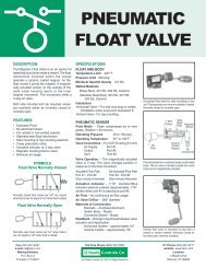
Pneumatic Pressure Switch<br />
The Pneumatic Pressure Switch combines a<br />
pressure sensing element and a spool valve to<br />
produce a switching device with an adjustable<br />
set point. The assembly is non-electric, using<br />
only <strong>air</strong> or inert gas in the switch unit.<br />
The pressure sensor is compatible with <strong>air</strong>,<br />
water, steam, oil and many corrosive liquids or<br />
gases. Setpoint is adjustable – vacuum up to 6000 psig.<br />
Air signals from the 5 ported 4-way valve in the switch unit can be<br />
either vacuum or positive pressure up to 100 psig. Request<br />
Bulletin OK-043.<br />
Pneumatic Liquid Level Switch<br />
The Liquid Level Switch is an <strong>air</strong> sensor for<br />
detecting liquid level inside a vessel. The float<br />
mechanism mounted within the vessel operates<br />
a ceramic coated magnet. A magnetically<br />
actuated sensor on the outside of the solid<br />
metal housing reacts to the inner magnet movement.<br />
The movement shifts a 3-way <strong>air</strong> valve.<br />
Both side mounted (shown here) and top mounted<br />
units are available. Wetted materials are brass or stainless steel.<br />
The magnetic sensor unit operates at <strong>air</strong> pressure from 30 to 100<br />
psig. The 3-way valve signals can pilot alarms or control elements.<br />
Request Bulletin OK-242.<br />
Pneumatic Flow Switch<br />
The Pneumatic Flow Switch is an <strong>air</strong> sensor<br />
for detecting the flow of liquids or gases in<br />
a pipe. A paddle extends into the fluid and deflects<br />
as the stream velocity increases or decreases.<br />
Various sized paddles establish the particular<br />
fluid stream flow rate at which the external magnetic<br />
sensor is actuated.<br />
The <strong>air</strong> sensor is a 3-way valve which operates at<br />
pressures from 30 to 100 psig. Flow switch units are available from<br />
1/2" to 2" NPT. Wetted materials are brass or stainless steel.<br />
Request Bulletin OK-268.<br />
Air Jet Proximity Sensor<br />
The Air Jet Proximity Sensor is a non-contact<br />
no-moving-part sensor, capable of detecting<br />
the presence of an object at ranges<br />
up to 1/8". In the absence of an object,<br />
<strong>air</strong> flows freely from the sensor resulting<br />
in a near zero output signal. The presence of an object within the<br />
sensing range deflects the normal <strong>air</strong> flow and results in a positive<br />
output signal.<br />
Air supply pressure is 0.5 to 10 psig. Output signals are low<br />
pressure and sufficient to actuate <strong>air</strong>/electric switches or <strong>air</strong>/<strong>air</strong><br />
amplifiers. Request Brochure OK-098.<br />
Pneumatic <strong>Controls</strong> 23<br />
SENSORS<br />
Pneumatic Temperature Switch<br />
The Pneumatic Temperature Switch combines a<br />
temperature sensing element and a spool valve to<br />
produce a switching device with an adjustable set<br />
point. The assembly is non-electric, using only <strong>air</strong> or<br />
inert gas in the switch unit.<br />
The temperature sensor is available in direct mount<br />
(shown here) or with a bulb and capillary. Wetted<br />
materials are copper or stainless steel.<br />
Air signals from the 5 ported 4-way valve in the<br />
switch unit can be either vacuum or positive pressure up to<br />
100 psig. Request Bulletin OK-088.<br />
Pneumatic Liquid Level Indicator<br />
The Liquid Level Indicator displays the height<br />
of liquid above the tip of an <strong>air</strong> tube immersed<br />
in the liquid. A small amount of <strong>air</strong><br />
bubbles through the liquid of a vented vessel.<br />
The back pressure in the sense tube is<br />
displayed on a gage. This back pressure<br />
corresponds to the height of the liquid above the top of the sense tube.<br />
Ranges of liquid height vary from 0-1 in. to 0-60 ft. Request<br />
Bulletin OK-267.<br />
Differential Pressure Flow Switch<br />
The Differential Pressure Flow Switch uses a calibrated<br />
flow element to provide pressure signals to an<br />
adjustable setpoint differential pressure electric<br />
switch. Gases or liquids can be used. Wetted<br />
materials are aluminum, brass or stainless steel.<br />
Adjustable flow rate setpoints are available for<br />
water flow ranges from 15-50 sccm to<br />
4-12 GPM. Request Bulletin OK-269.<br />
Magnetic Proximity Sensor<br />
The Magnetic Proximity Sensor detects<br />
the presence of a magnetic or steel part in<br />
its near vicinity. The 3-way normally closed<br />
<strong>air</strong> valve is actuated when in the presence<br />
of a small magnet or steel part. The valve<br />
deactuates when the small magnet or steel<br />
part is removed.<br />
Since magnetic fields penetrate materials such as<br />
aluminum or stainless steel, the proximity sensor readily detects a<br />
properly polarized magnetic piston in a cylinder constructed with<br />
aluminum or stainless steel barrels. It is often used in place of limit<br />
switches to detect end of stroke position.<br />
The sensor is available with mounting straps for attachment to a<br />
round cylinder barrel. Request Brochure OK-248.<br />
P.O. BOX Q • TRUMBULL, CT 06611 • CT PHONE (203) 261-6711 • TOLL FREE PHONE (800) 533-3285 • FAX (203) 261-8331<br />
© O'KEEFE CONTROLS CO. • 2001 ALL RIGHTS RESERVED e-mail ca@okcc.com • website www.okcc.com
PRODUCTS MANUFACTURED<br />
BY<br />
O'KEEFE CONTROLS CO.<br />
Precision Orifices<br />
"Over 6000 Choices"<br />
Sapphire, Brass, Stainless Steel<br />
Micro-Orifices ®<br />
"Diameter as small as .0003 inch"<br />
Brass or Stainless Steel<br />
In-Line Screen Products<br />
"Protect Small Orifices"<br />
10 to 100 microns<br />
Miniature Stainless Steel Fittings<br />
"Adapters, Bulkheads,<br />
Couplings, Barbs"<br />
Check Valves<br />
"Vacuum to 2000 psig"<br />
Brass or Stainless Steel<br />
Fixed Flow <strong>Controls</strong><br />
"For Cylinder Speed Control"<br />
Brass or Stainless Steel<br />
Pneumatic Sensors<br />
"For Pressure, Temperature,<br />
Flow, Level, Proximity"<br />
Fax (203) 261-8331 Toll Free Phone (800) 533-3285 CT Phone (203) 261-6711<br />
e-mail ca@okcc.com website www.okcc.com<br />
Mailing Address Location<br />
P.O. Box Q 4 Maple Drive<br />
Trumbull, CT 06611 © <strong>O'Keefe</strong> <strong>Controls</strong> Co. 2001 All Rights Reserved Monroe, CT 06468