Chapter 5 Robust Performance Tailoring with Tuning - SSL - MIT
Chapter 5 Robust Performance Tailoring with Tuning - SSL - MIT
Chapter 5 Robust Performance Tailoring with Tuning - SSL - MIT

You also want an ePaper? Increase the reach of your titles
YUMPU automatically turns print PDFs into web optimized ePapers that Google loves.
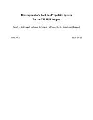
Table 6.1: RWA disturbance model parameters.<br />
Name Value Units Description<br />
f1 0 Hz minimum wheel speed<br />
f2 50 Hz maximum wheel speed<br />
nrwa 3 N/A number of wheels<br />
α 30 degrees orientation angle<br />
θ 45 degrees orientation angle<br />
γ 0 degrees orientation angle<br />
drwa 0.25 m distance to spacecraft origin<br />
be used to drive the structural model, the number and configuration of the wheels<br />
must be taken into account. A multiple wheel model was developed by H. Gutierrez<br />
that combines the disturbance models of n wheels in a given configuration into a single<br />
RWA disturbance model [50]. This model is a 6x6 matrix of power and cross-spectral<br />
densities of the RWA vibrations transformed to the body-frame of the spacecraft.<br />
The disturbance model implemented in this version of the TPF model is a stochas-<br />
tic, multiple-wheel model created using the DOCS docs_psd_rwa_dist.m function.<br />
The model parameters used are listed in Table 6.1. The wheel speeds are assumed<br />
to range from 0 to 3000 RPM. The angles α, θ, andγ locate the three wheels <strong>with</strong><br />
respect to the body-frame spacecraft axes. The parameter drwa is the radial distance<br />
from the wheel centers to the spacecraft origin. In the current TPF configuration,<br />
the spin-axes of the three wheels are 45 ◦ from the TPF Z-axis, and their projections<br />
in the X-Y plane are spaced 120 ◦ apart as shown in Figure 6-3(a). The modelled<br />
disturbance PSDs are shown in Figure 6-3(b).<br />
6.1.2 Vibration Isolation<br />
Due to the precision required by the TPF instrument it is likely that the RWA will<br />
be isolated from the truss structure that supports the optics. Simple models of a<br />
two-stage isolation system based on the isolator design for SIM are included in the<br />
integrated model. The first model represents an isolator located between the RWA and<br />
the bus, and the second isolates the supporting structure from the bus. The isolator<br />
models are included in the TPF SCI model by placing two second-order systems in<br />
185